

Page 1
Private Communication Systems
Mobile Phones
S6 GSM/PCN
Level 2.5
Repair Documentation
V1.4
V1.4 Page 1 of 17 PN MP ST
D. Schnoor
08/98
Page 2
Private Communication Systems
Mobile Phones
Table of Contents:
1 RF CONNECTOR
...................................................................................................................................................................................3
2 EXCHANGE OF EXTERNAL CONNECTOR
...................................................................................................................................................................................6
3 1A FUSE
.................................................................................................................................................................................10
4 RINGER
.................................................................................................................................................................................13
5 ANNEX................................................................................................................................................................16
V1.4 Page 2 of 17 PN MP ST
D. Schnoor
08/98
Page 3

Private Communication Systems
Mobile Phones
1RF Connector
1.1Affected Units
1.1.1Type: S6 GSM / PCN
1.1.2Affected IMEIs / Date Codes: All / All
1.1.3Affected SW-Versions: All
1.1.4Fault Code for LSO reporting: 3RFC
1.2Fault Description
1.2.1Fault Symptoms for customers:
Customers experience a low Rx sensitivity of the handset, having problems registering to the network and
making calls.
1.2.2Fault Symptom on GSM-Tester:
The GSM-Tester will show a low Tx-Power only on the
internal antenna (aerial coupler measurement!).
1.3Priority:
........ Mandatory
........ Repair
........ Optional
........ Not Yet Defined
V1.4 Page 3 of 17 PN MP ST
D. Schnoor
08/98
Page 4

Private Communication Systems
Mobile Phones
1.4Repair Documentation
1.4.1Description of procedure:
1.4.1.1Diagnosis
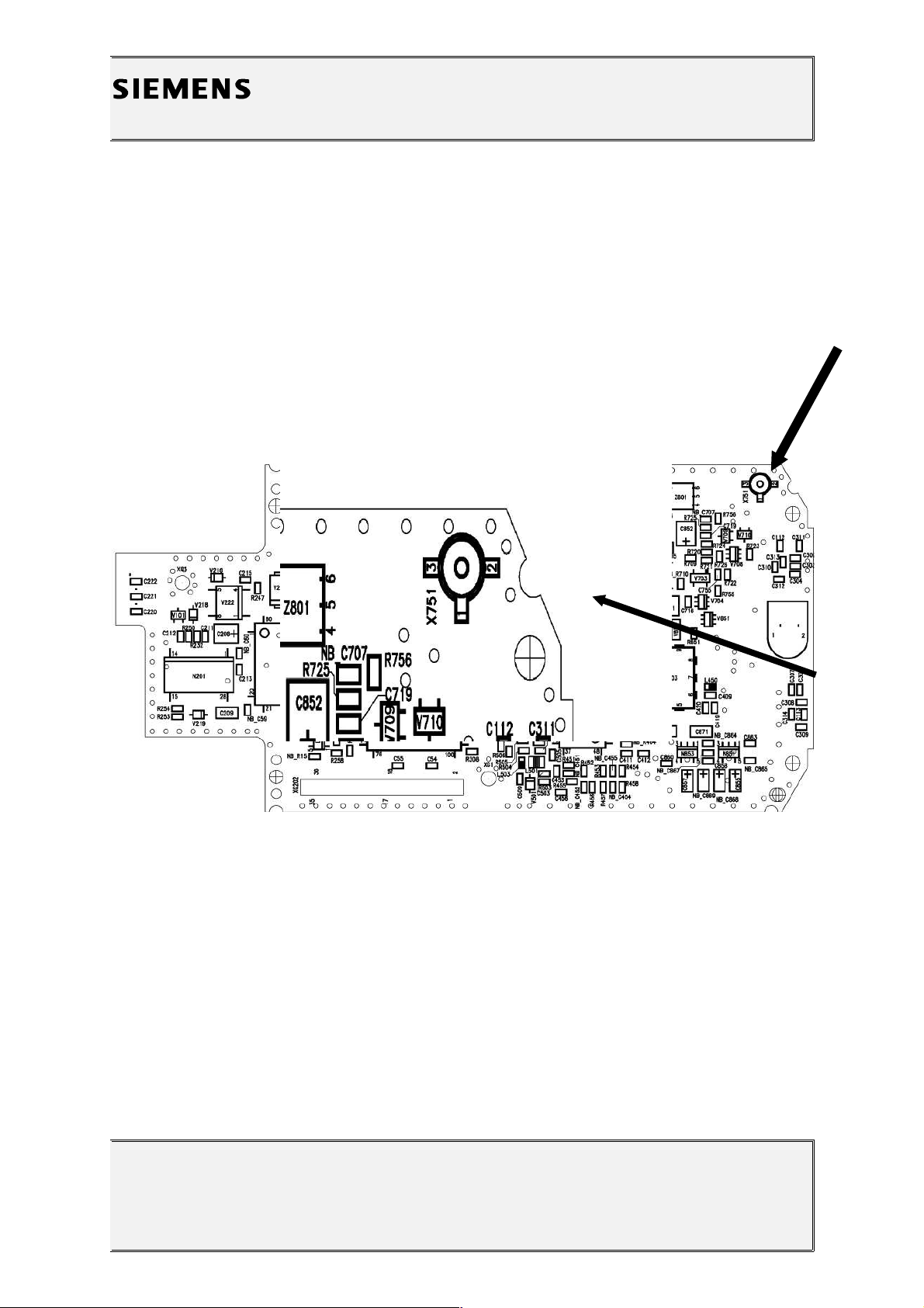
Visually check the status of the antenna connector. Look for a bent
contact or dry soldering joint.
1.4.1.2Repair by component change
Use hot air blower to remove defective connector.
Resolder new connector afterwards.
Pin 1 is the RF pin, pins 2 and 3 are ground.
1.4.1.3Repair by SW-Booting
Not possible!
1.4.1.4Test
Retest handset after repair.
1.4.2List of needed material
1.4.2.1Components
Connector X751
Part-Number: L24859-Z1359-A24
1.4.2.2 Jigs and Tools
Soldering Iron
Hot Air Blower
1.4.2.3Special Tools
None
V1.4 Page 4 of 17 PN MP ST
D. Schnoor
08/98
Page 5
Private Communication Systems
Mobile Phones
1.4.2.4Working materials
Desolder Wick / Braid
Solder
Flux
1.4.3Drawings
V1.4 Page 5 of 17 PN MP ST
D. Schnoor
08/98
Figure 1: S6 Board RF Connector Side
Figure 2: S6 RF Connector (X751) Placement (Top View)
Page 6

Private Communication Systems
Mobile Phones
2Exchange of External Connector
2.1Affected Units
2.1.1Type: S6 GSM / PCN
2.1.2Affected IMEIs / Date Codes: All / All
2.1.3Affected SW-Versions: All
2.1.4Fault Code for LSO reporting 3MOC
2.2Fault Description
2.2.1Fault Symptoms for customers:
Customers are unable to charge the battery, since
the charging pin is broken/missing
Network search
Connector is physically damaged
2.2.2Fault Symptom on GSM-Tester:
Power problems on the external and internal antenna
Location update problems on external and internal
antenna
2.3Priority:
........ Mandatory
........ Repair
........ Optional
........ Not Yet Defined
V1.4 Page 6 of 17 PN MP ST
D. Schnoor
08/98
Page 7

Private Communication Systems
Mobile Phones
2.4Repair Documentation
2.4.1Description of procedure:
2.4.1.1Diagnosis
There is a mechanical switch in the bottom connector which switches
between the external and internal antenna of the handset.
The switch is located behind pins 23, 24, 25 and 26, while 23 and 26
are ground connections and 24 and 25 are RF connections.
Dry joints at these pins will interrupt the RF connection both to the
internal and external antenna of the handset, resulting in „network
search“ problems.
See figure 2 for the location of the pins!
Furthermore if the connector is physically damaged (missing charging
pin), it will have to be replaced.
2.4.1.2Repair by component change
Use hot air blower to remove defective connector.
Attention: Make sure that the neighbouring components are not
exposed to heat!
Clean solder pads with desoldering wick afterwards.
Fix new connector and solder ground connections first (Pins 18, 20,
21, 22, 23 and 26 in figure 2).
Then the other connections are soldered, using only very little flux.
It is highly recommended to use a microscope during the work!
If too much flux is used, the connector will not work anymore!
2.4.1.3Repair by SW-Booting
Not possible!
2.4.1.4Test
After the connector change check solder joints with a microscope.
Check charging functionality by connecting a travel charger to
charging plug. If the connection is right, the charging symbol must
appear on the
handset display (make sure that a battery is inserted!).
V1.4 Page 7 of 17 PN MP ST
D. Schnoor
08/98
Page 8

Private Communication Systems
Mobile Phones
2.4.2List of needed material
2.4.2.1Components
External Connector
Part-Number: L36851-Z1351-A70
2.4.2.2 Jigs and Tools
Soldering Iron
Hot Air Blower
2.4.2.3Special Tools
None
2.4.2.4Working materials
Desolder Wick / Braid
Solder
Flux
2.4.3Drawings
V1.4 Page 8 of 17 PN MP ST
D. Schnoor
08/98
Figure 1: S6 Board External Connector Side
Page 9

Private Communication Systems
Mobile Phones
V1.4 Page 9 of 17 PN MP ST
D. Schnoor
08/98
Figure 2: S6 External Connector (X203) Placement (Top View)
Page 10

Private Communication Systems
Mobile Phones
31A Fuse
3.1Affected Units
3.1.1Type: S6 GSM / PCN
3.1.2Affected IMEIs / Date Codes: All / All
3.1.3Affected SW-Versions: All
3.1.4Fault Code for LSO reporting 3FU1
3.2Fault Description
3.2.1Fault Symptoms for customers:
Customers are unable to charge the battery.
3.2.2Fault Symptom on GSM-Tester:
This fault cannot be detected with a GSM-Tester.
3.3Priority:
........ Mandatory
........ Repair
........ Optional
........ Not Yet Defined
V1.4 Page 10 of 17 PN MP ST
D. Schnoor
08/98
Page 11

Private Communication Systems
Mobile Phones
3.4Repair Documentation
3.4.1Description of procedure:
3.4.1.1Diagnosis
If the customer connects a charger which delivers a current > 1
ampere, the fuse F201 will blow to protect the charging curcuitry.
The Siemens chargers have a current limit of 700mA.
The status of F201 can easily be checked with a multimeter. If the
resistance is infinit, the fuse is blown.
3.4.1.2Repair by component change
Use soldering iron to remove defective fuse.
Resolder new fuse afterwards.
3.4.1.3Repair by SW-Booting
Not possible!
3.4.1.4Test
Check resistance of fuse (< 1 Ohm) and check charging functionality
afterwards by connecting a travel charger to complete phone.
If you have a battery inserted, the charging symbol must be visible on
the handset display.
3.4.2List of needed material
3.4.2.1Components
Fuse F201 (1A)
Part-Number: L36145-A820-Y7
V1.4 Page 11 of 17 PN MP ST
D. Schnoor
08/98
Page 12

Private Communication Systems
Mobile Phones
3.4.2.2 Jigs and Tools
Soldering Iron
3.4.2.3Special Tools
None
3.4.2.4Working materials
Desolder Wick / Braid
Solder
Flux
3.4.3Drawings
V1.4 Page 12 of 17 PN MP ST
D. Schnoor
08/98
Figure 1: S6 Board Fuse Side
Figure 2: S6 Fuse (F201) Placement (Top View)
Page 13

Private Communication Systems
Mobile Phones
4Ringer
4.1Affected Units
4.1.1Type: S6 GSM / PCN MMI
4.1.2Affected IMEIs / Date Codes: All / All
4.1.3Affected SW-Versions: All
4.1.4Fault Code for LSO reporting 3RIN
4.2Fault Description
4.2.1Fault Symptoms for customers:
Ringer tone is not audible or distorted.
4.2.2Fault Symptom on GSM-Tester:
Ringer test fails.
4.3Priority:
........ Mandatory
........ Repair
........ Optional
........ Not Yet Defined
V1.4 Page 13 of 17 PN MP ST
D. Schnoor
08/98
Page 14

Private Communication Systems
Mobile Phones
4.4Repair Documentation
4.4.1Description of procedure:
4.4.1.1Diagnosis
See symptoms above
4.4.1.2Repair by component change
Use soldering desoldering braid to remove defective ringer.
Resolder new ringer afterwards.
4.4.1.3Repair by SW-Booting
Not possible!
4.4.1.4Test
Retest handset.
V1.4 Page 14 of 17 PN MP ST
D. Schnoor
08/98
Page 15

Private Communication Systems
Mobile Phones
4.4.2List of needed material
4.4.2.1Components
Ringer
Part-Number: L36178-Z2-C16
4.4.2.2 Jigs and Tools
Soldering Iron
Desoldering braid
4.4.2.3Special Tools
None
4.4.2.4Working materials
Desolder Wick / Braid
Solder
Flux
V1.4 Page 15 of 17 PN MP ST
D. Schnoor
08/98
Page 16

Private Communication Systems
Mobile Phones
5ANNEX
5.1Dry joints / soldering problems
The S6 GSM/PCN, S6Classic GSM/PCN and the E10 have a mechanical antenna-switch in
the bottom connector (molex connector).
As a consequence of this a lot of RF problems will come up, if the soldering is bad.
Due to the difficult production soldering process of the bottom connectors, a relatively high
percentage of handsets could be affected by this problem.
RF problems are for example a low or completely missing output power, or a missing RXsensitivity.
In order to analyze the situation, please use the diagram below.
Note: The S10 / S11 does not have a mechanical switch inside the molex connector, so dry
joints will only affect the external handset antenna.
V1.4 Page 16 of 17 PN MP ST
D. Schnoor
08/98
Page 17

Private Communication Systems
Mobile Phones
V1.4 Page 17 of 17 PN MP ST
D. Schnoor
08/98
RF Problems
on internal and
external
antenna
RF Problems on the
external antenna
only
RF problems on the
internal antenna
only *
NO NO
Yes
Change X203
Change or resolder
X751
Yes
RF contact on X203
(molex connector)
physically damaged?
Antenna connector
(X751) to MMI Module
damaged or badly
soldered?
Dry solder joints on pins
23, 24, 25, 26 of X203
(molex connector) ?
Resolder pins
Yes
Dry solder joints on pins
1,2 or 3 of duplex filter
(Z752) ?
No
Resolder pins
Yes
Exchange RF-module
No
* Internal antenna problems could also be caused by the display
module. Make sure that you test the board with a reference display
module.
 Loading...