

Siemens S-60 Quick Start Manual
S-60 CROSSING
AUXILIARY OVERLOAD DEVICE
QUICK START GUIDE
Document No. SIG-QG-09-01A.1
The Auxiliary Overload Device (AOD) is an add-on device for
the S-60 Crossing Gate, with a Rev C or Older Main Board
installed. The AOD is designed to detect an entrance gate
motor stall based on the supply voltage and amount of tim e
the S-60 actively drives the gate motor. The AOD, upon
detection of a stall condition, will engage a relay, i nterrupti ng
the supply of power to the motor and have the gate arm
descend in a controlled manner. The AOD is powered by the
S-60 drive mechanisms and is not capable of introducing
foreign energy or otherwise interfering with the S-60 safety
related motor drive in a manner that would cause an unsafe
condition. Refer to the S-60 Crossing Manual for further
information. (Siemens Doc. No.: 074050).
WARNING
THIS PROCEDURE WILL REQUIRE TEMPORARY OPENING
AND CLOSING OF HIGHWAY CROSSING WARNING DEVICE
CIRCUITS. PRIOR TO PERFORMING, TAKE THE NECESSARY
PRECAUTIONS TO WARN PEDESTRIANS, PERSONNEL,
TRAINS, AND VEHICLES IN THE AREA UNTIL PROPER
OPERATION IS RESTORED AND VERIFIED.
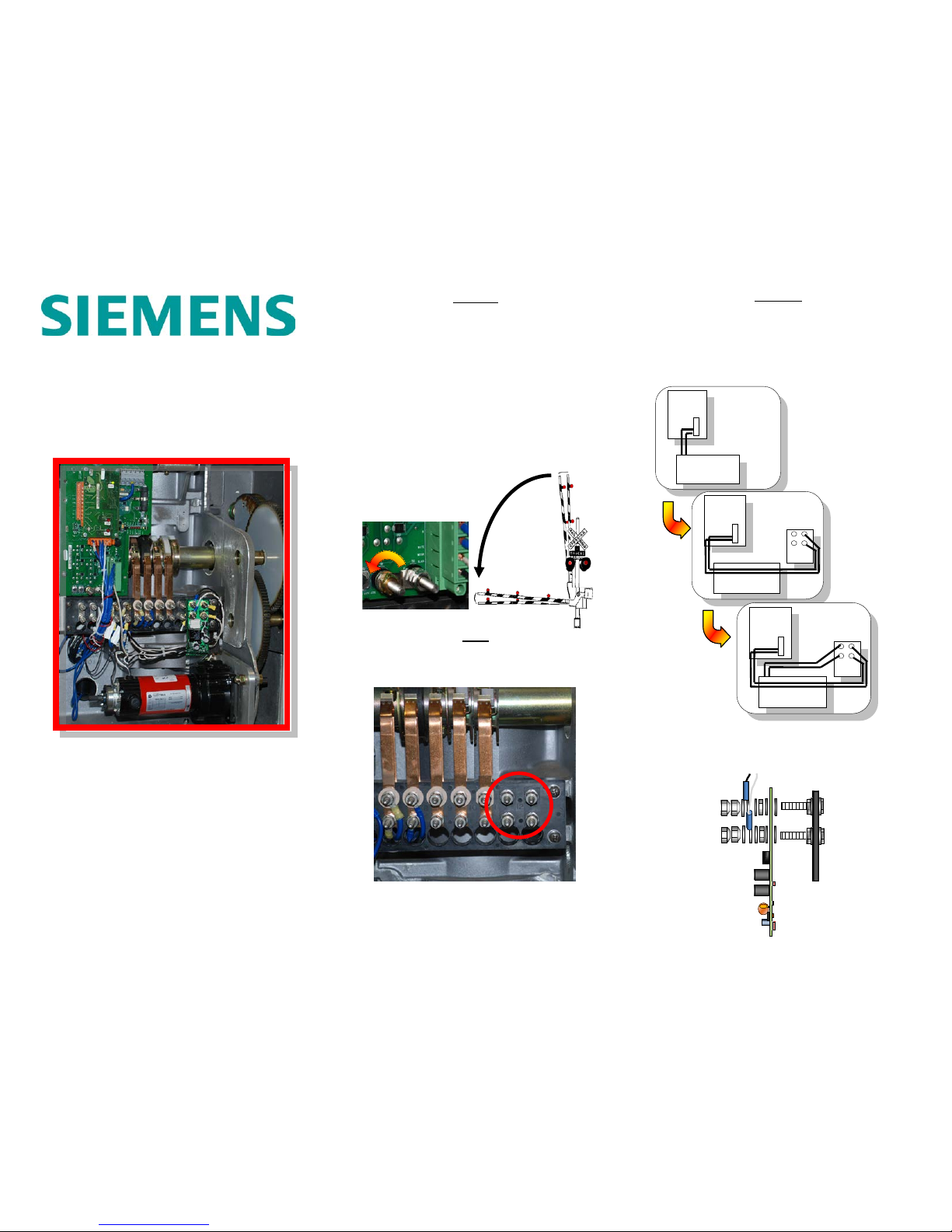
Prepare Crossing
Prepare the crossing for installation. Open the Gold-Nut,
which will lower the Gate Arm. See S-60 Crossing Gate
Manual (Siemens Document Number 074050) for further
information.
NOTE
Visually inspect the gate mechanism to ensure there are no
cams and/or wires attached to terminals T11 t op and bottom
and T12 top and bottom.
Gate Mechanism Visual Inspection
Gate Mechanism Visual Inspection
WARNING
IT IS NECESSARY TO FOLLOW THIS PROCEDURE AND
ENSURE WIRES ARE INSTALLED IN THE PROPER
LOCATIONS FOR THE GATE MECHANISM TO OPERATE
PROPERLY.
Wiring Overview
The following is an overview of the AOD wiring:
Hardware Installation Overview
The following is the hardware sequence for the AOD
installation.
MOTOR
EXISTING
CONFIGURATION
GATE
CONTROL
BOARD
AOD
GATE
CONTROL
BOARD
MOTOR
GATE
CONTROL
TO
AOD
AOD
GATE
CONTROL
BOARD
MOTOR
TO
AOD
MOTOR
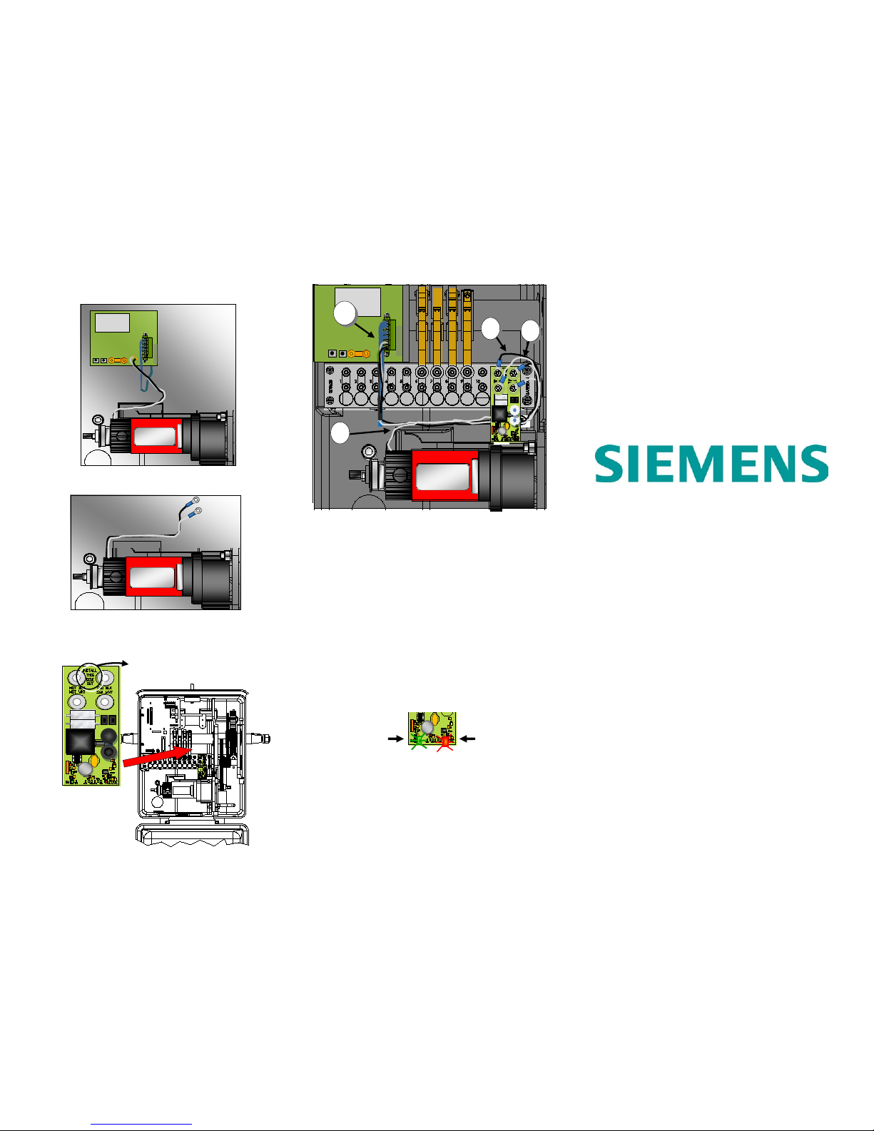
Installation Procedure
1. Remove motor wires from P4 on Main Board
2. Install Ring Terminals on Motor wires.
3. Install AOD Board on AAR Terminals (#11 and #12).
Mount the AOD Board with “INSTALL THIS SIDE OUT”
facing front as shown below.
4. Install the wiring using the following procedure:
A). Loc ate prepared wires provided with the AOD Kit and
install bare ends into P4 S connector, where the motor wires
were removed. Install White wire on top and Blac k wire on
the bottom as shown in diagram above.
B). Connect Ring Terminal ends of the wires to the AAR
Terminals (#12), Black on 12T (top), White 12B (bottom).
C.) Connect Motor wire Ring Terminals to AAR Terminals
(#11), Black on 11T (top), White on 11B (bottom).
D.) Bundle and tie-wrap wires.
Testing Installation
1.) Close the Gold-Nut. Cycle the Gate a m i nimum of 2 times
to verify gate is operating properly. The AOD Board “ON”
LED (Green) will illuminate with each mot or operation. Note
the Red “ACTIVE” LED will illuminate for 3 m inutes in the
event of a low supply voltage, causing the motor to be in a
stall condition.
2.) Perform any other tests as prescribed by the railroad
and/or authority to ensure proper operation of t he warning
system and compliance with current rules and regulations.
3.) Restore Crossing to normal operation.
Contact Siemens Customer Service with any questions.
Siemens Rail Automation Corp.
2400 Nelson Miller Parkway
Louisville, Kentucky 40223
California R&D
9568 Archibald Ave., Suite 100
Cucamonga, California 91730
1-800-793-SAFE (7233)
Copyright © 2009-2014 Siemens
All rights reserved.
N-12
DOWN
POWER
B-12
MOTOR
MOTOR
MAINTENANCE
PRESS TO
VIEW LEDS
P4
WARNING
REMOVAL OF P4 CAN
RESULT IN
UNCONTROLLED DESCENT
OF GATE AR M
INSTALL
THIS
SIDE
OUT
ON LED
Illuminates
ACTIVE LED
Illuminates
3 Minutes
MAINTENANCE
PRESS TO
VIEW LEDS
P4
A
C
B
MAINTENANCE
PRESS TO
VIEW LEDS
P4
A
C
B
D
 Loading...