

Page 1
ISO transponder
8.7.2
Ordering data
Article number
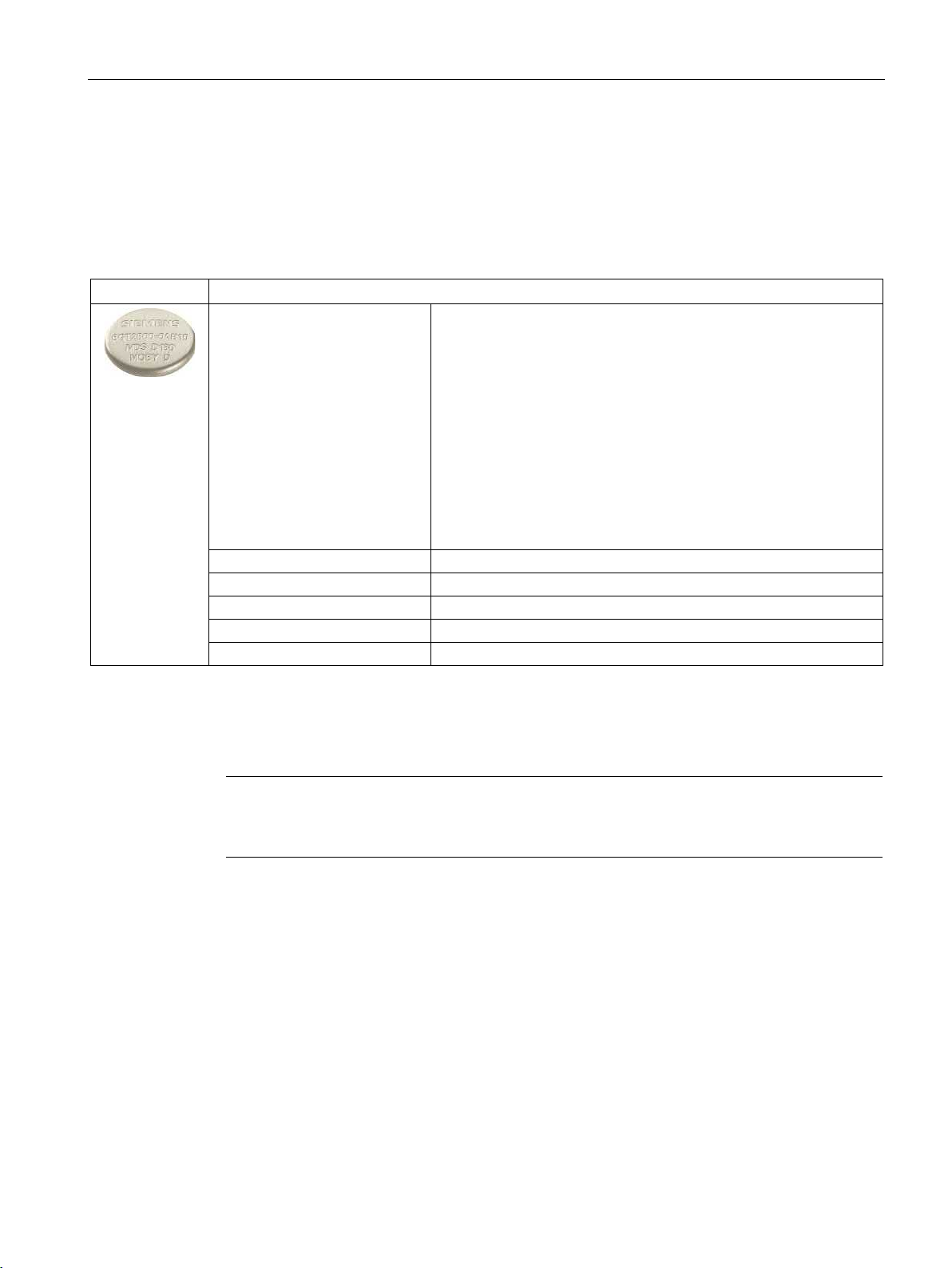
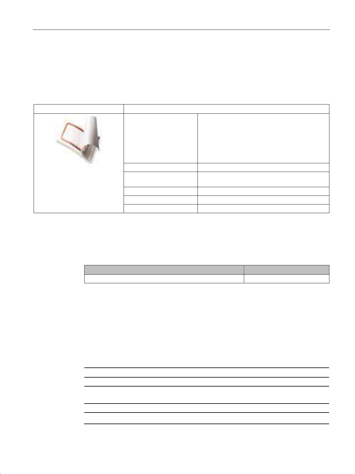
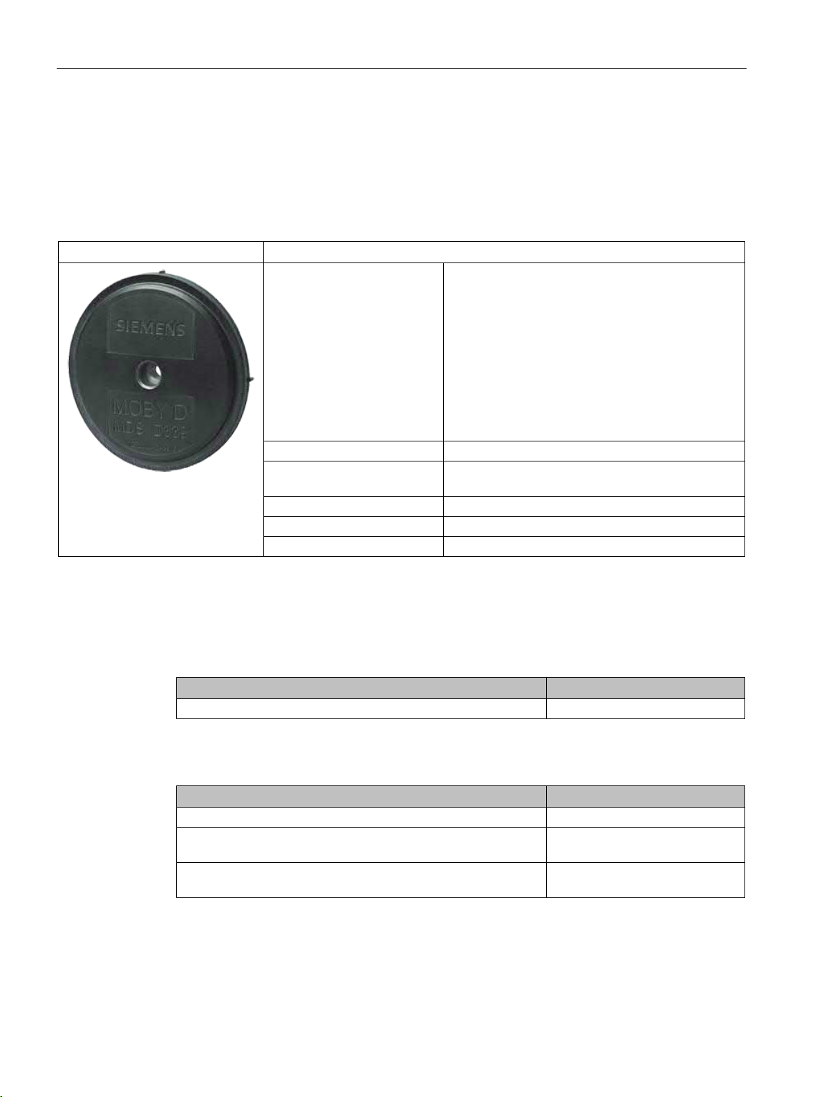
MDS D139
6GT2600-0AA10
Article number
Spacer
6GT2690-0AA00
(Ø x H): 22 x 60 mm
(Ø x H): 22 x 47 mm
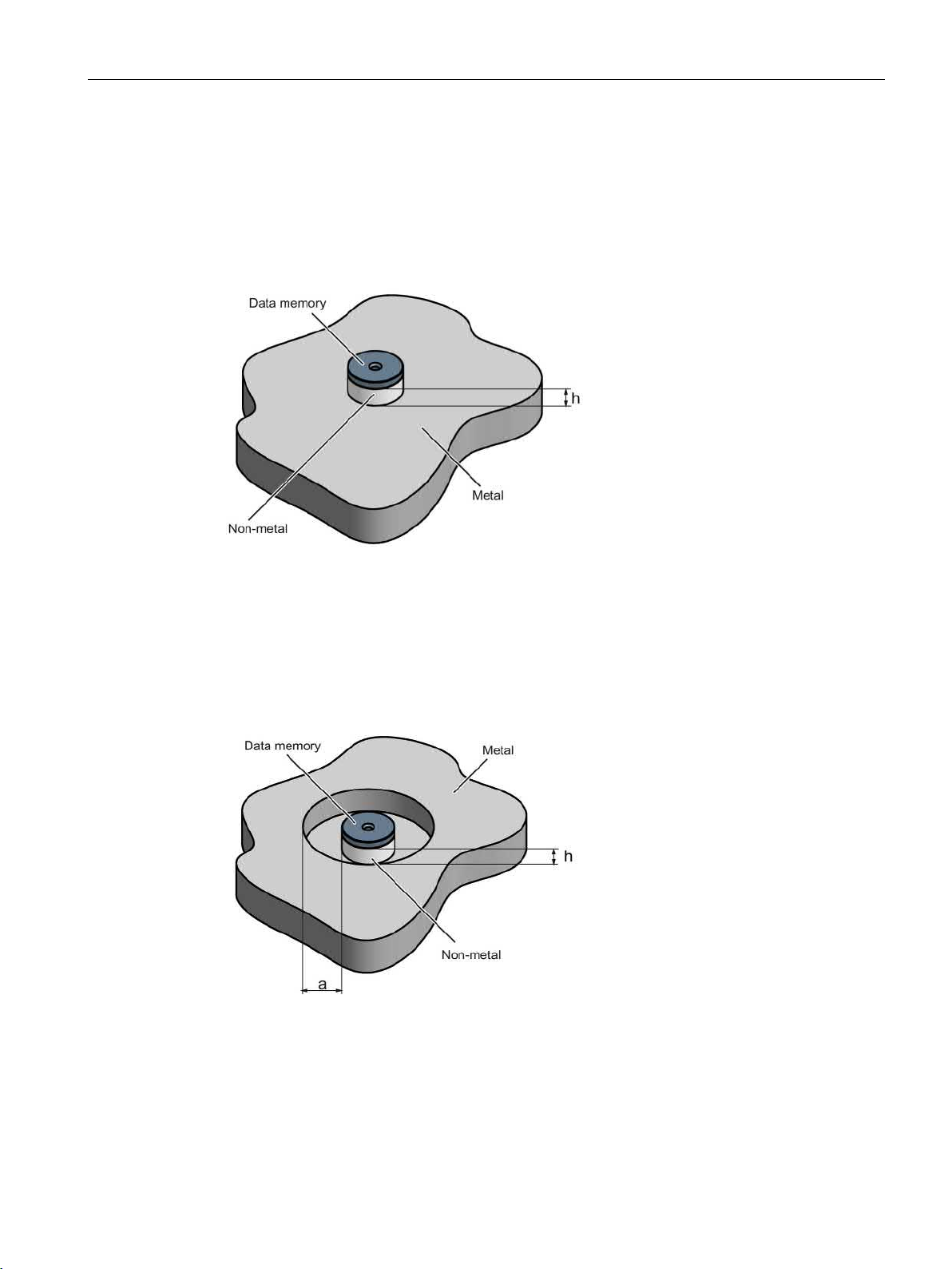
8.7.3
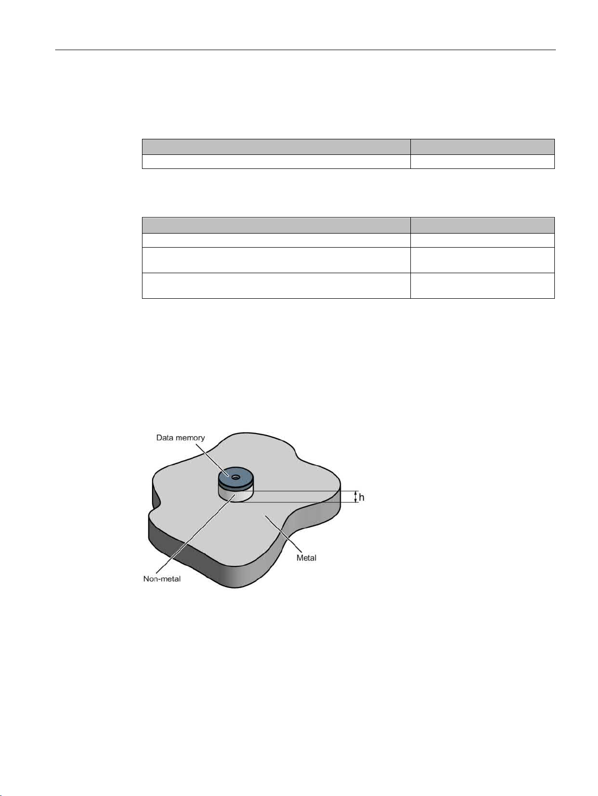
Mounting on metal
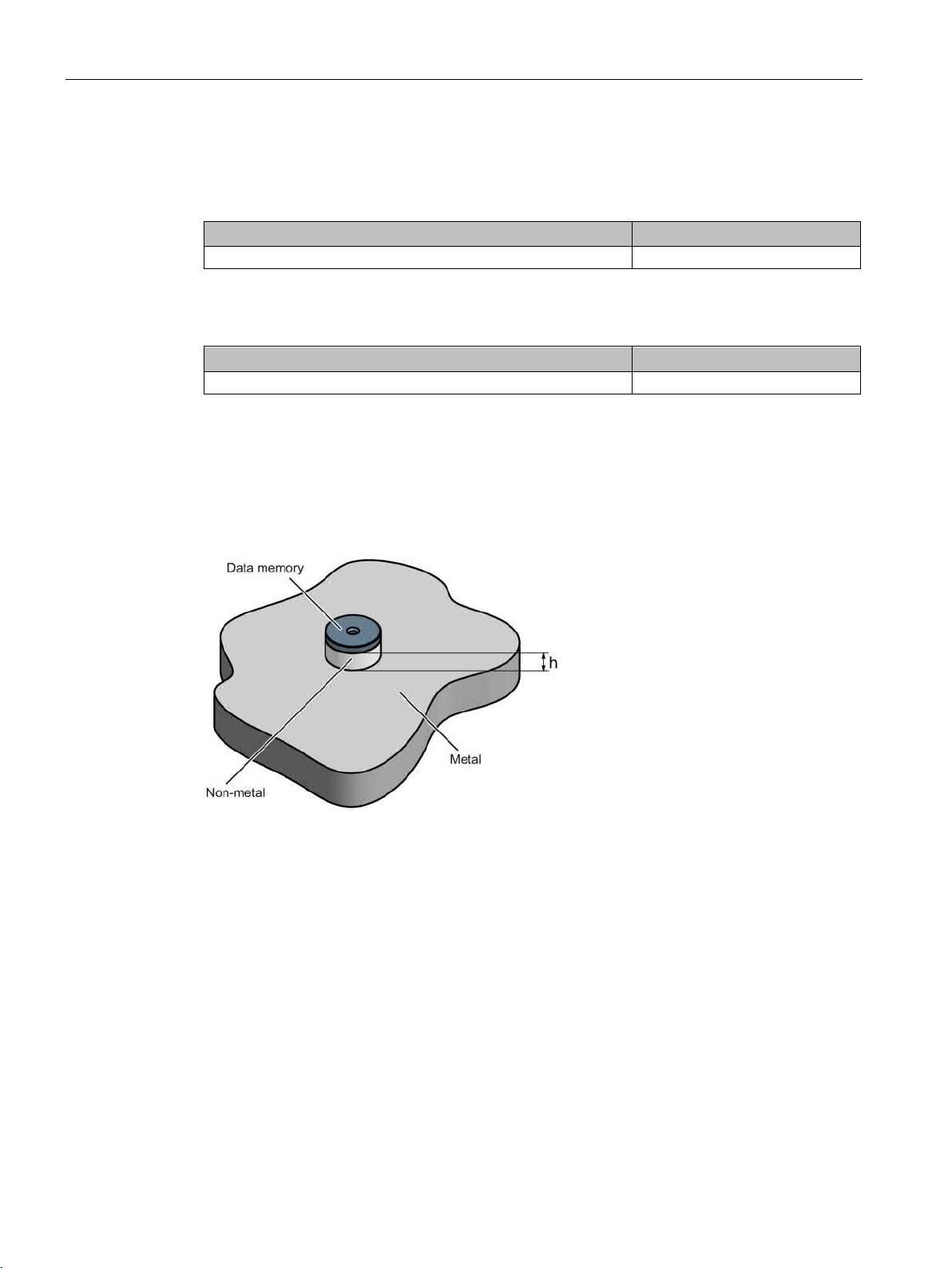
Mounting on metal
h
≥ 30 mm
8.7 MDS D139
Table 8- 15 Ordering data for MDS D139
Table 8- 16 Ordering data for MDS D139 accessory
Direct mounting of the MDS D139/D339 on metal is not allowed. A distance of ≥ 30 mm is
recommended. This can be achieved using spacers (see "Ordering data (Page 441)").
Quick change holder
Quick change holder
6GT2690-0AH00
6GT2690-0AH10
SIMATIC RF300
System Manual, 07/2017, C79000-G8976-C345-07
Figure 8-14 Mounting the MDS D139/D339 on metal with spacer
301
Page 2
ISO transponder
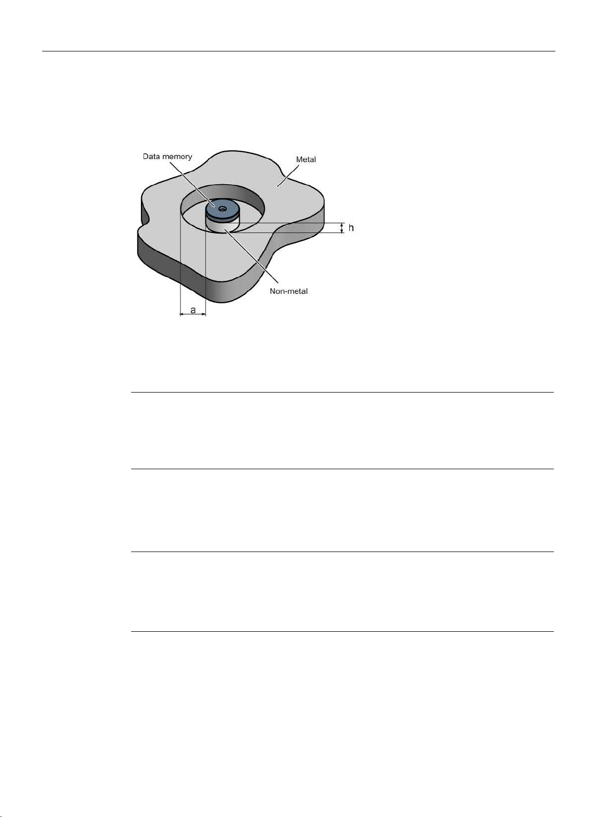
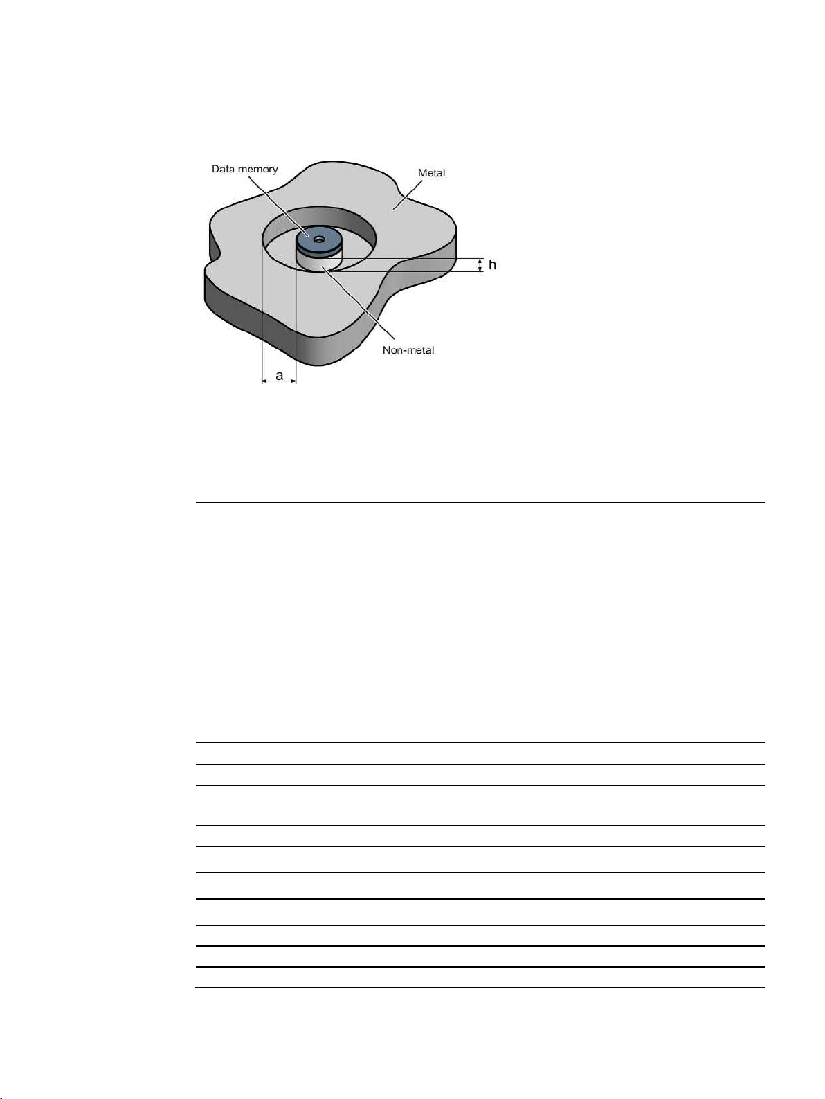
Flush-mounting
h
≥ 30 mm
a
≥ 100 mm
Note
Going below the distances
If the distances (a and h) are not observed, a reduction of the field data results. It is possible
to mount the MDS with
recommended that a test is performed in critical applications.
8.7.4
Cleaning the mobile data memory
Note
Do not clean the transponder with mechanical tools, sand
cleaning methods result in damage to the transponder.
Clean the transponder only with the chemical cleansing agents listed in Chapter
resistance of the readers and transponders
8.7 MDS D139
It is possible to mount the MDS D139/D339 in metal. With large antennas, for example ANT
D5, this leads to a reduction of ranges.
Figure 8-15 Flush-mounting of the MDS D139/D339 in metal with spacer
metal screws (M5). This has no tangible impact on the range. It is
-blasting or pressure hose. These
Chemical
(Page 97).
SIMATIC RF300
302 System Manual, 07/2017, C79000-G8976-C345-07
Page 3

ISO transponder
8.7.5
Technical specifications
6GT2600-0AA10
Product type designation
SIMATIC MDS D139
Memory
Memory configuration
Read cycles (at < 40 ℃)
> 1014
Write cycles (at < 40 ℃)
> 106
Data retention time (at < 40 ℃)
> 10 years
data of ISO transponders (MDS D) (Page 56)"
MTBF (Mean Time Between Failures)
228 years
Mechanical specifications
Housing
Recommended distance to metal
≥ 30 mm
Power supply
Inductive, without battery
Permitted ambient conditions
Ambient temperature
8.7 MDS D139
Table 8- 17 Technical specifications for MDS D139
• UID • 8 bytes
• User memory • 112 bytes EEPROM
• OTP memory • 16 bytes (EEPROM)
Write/read distance (Sg) Dependent on the reader used, see section "Field
• Material • PPS
• Color • Black
• during write/read access • -25 … +140 °C
• from +125 ℃: 20% reduction in the limit dis-
tance
• outside the read/write field • -40 to +220 ℃
• at +200 ℃: Tested up to 5000 hours or
6000 cycles
• at +220 ℃: Tested up to 2000 hours or
2000 cycles
• during storage • -40 to +100 ℃
SIMATIC RF300
System Manual, 07/2017, C79000-G8976-C345-07
303
Page 4

ISO transponder
6GT2600-0AA10
Shock according to EN 60721-3-7 Class 7M31)
500 m/s2
Vibration according to EN 60721-3-7 Class 7M31)
200 m/s2
Torsion and bending load
Not permitted
Design, dimensions and weight
Dimensions (Ø x H)
85 x 15 mm
Weight
50 g
1.5 Nm
1
2)
ing the MDS in high temperatures (expansion coefficient).
8.7.6
Use of the MDS D139 in hazardous areas
8.7 MDS D139
Degree of protection to EN 60529
Type of mounting 1 x M5 screw 2)
The values for shock and vibration are maximum values and must not be applied continuously.
For mounting with the spacer (6GT2690-0AA00), use a stainless steel M5 screw to avoid damag-
• IP68
• IPx9K
2 hours, 2 bar, +20 °C
steam jet: 150 mm; 10 to 15 l/min; 100 bar; 75
°C
The MDS D139 mobile data memory is classed as a piece of simple, electrical equipment
and can be operated in Protection Zone 2, Device Group II, Category 3G.
The following requirements of the 94/9/EC directive are met:
● EN 60079-0:2006
● EN 60079-15:2005
● EN 61241-0:2006
● EN 61241-1:2004
SIMATIC RF300
304 System Manual, 07/2017, C79000-G8976-C345-07
Page 5
ISO transponder
Identification
WARNING
Gefahr durch elektrostatische Entladungen
Potential electrostatic charging hazard
Danger potentiel de charges électrostatiques
Note
Installations- und Betriebsbedingungen für den Ex-Schutzbereich:
a
untersagt.
b) Das Gerät ist mechanisch geschützt zu montieren.
c) Die Montage muss auf einem geerdeten, leitenden Untergrund erfolgen.
d) Die Reinigung darf nur mit feuchtem T
Installation and operating conditions for hazardous areas:
a) Use of the equipment in the vicinity of processes generating high charges is not allowed.
b) The equipment must be mechanically protected when installed.
c) Installation must be p
d) Cleaning only with a wet cloth
Conditions d'installation et de mise en oeuvre pour la zone de protection Ex :
a) L'utilisation de l'appareil près de processus générant de fortes charges est interd
b) L'appareil doit être monté de manière à être protégé mécaniquement.
c) Le montage doit être effectué sur un socle conducteur mis à la terre.
d) Nettoyage uniquement avec un chiffon humide
8.7 MDS D139
II 3 G Ex nA II T2
II 3 D Ex tD A22 IP68 T 220°C
KEMA 09 ATEX 0133 X
Ta: -25 ... +220°C
) Der Einsatz des Gerätes in der Nähe von stark ladungserzeugenden Prozessen ist
uch erfolgen.
erformed on a grounded and conductive mounting surface.
ite.
SIMATIC RF300
System Manual, 07/2017, C79000-G8976-C345-07
305
Page 6
ISO transponder
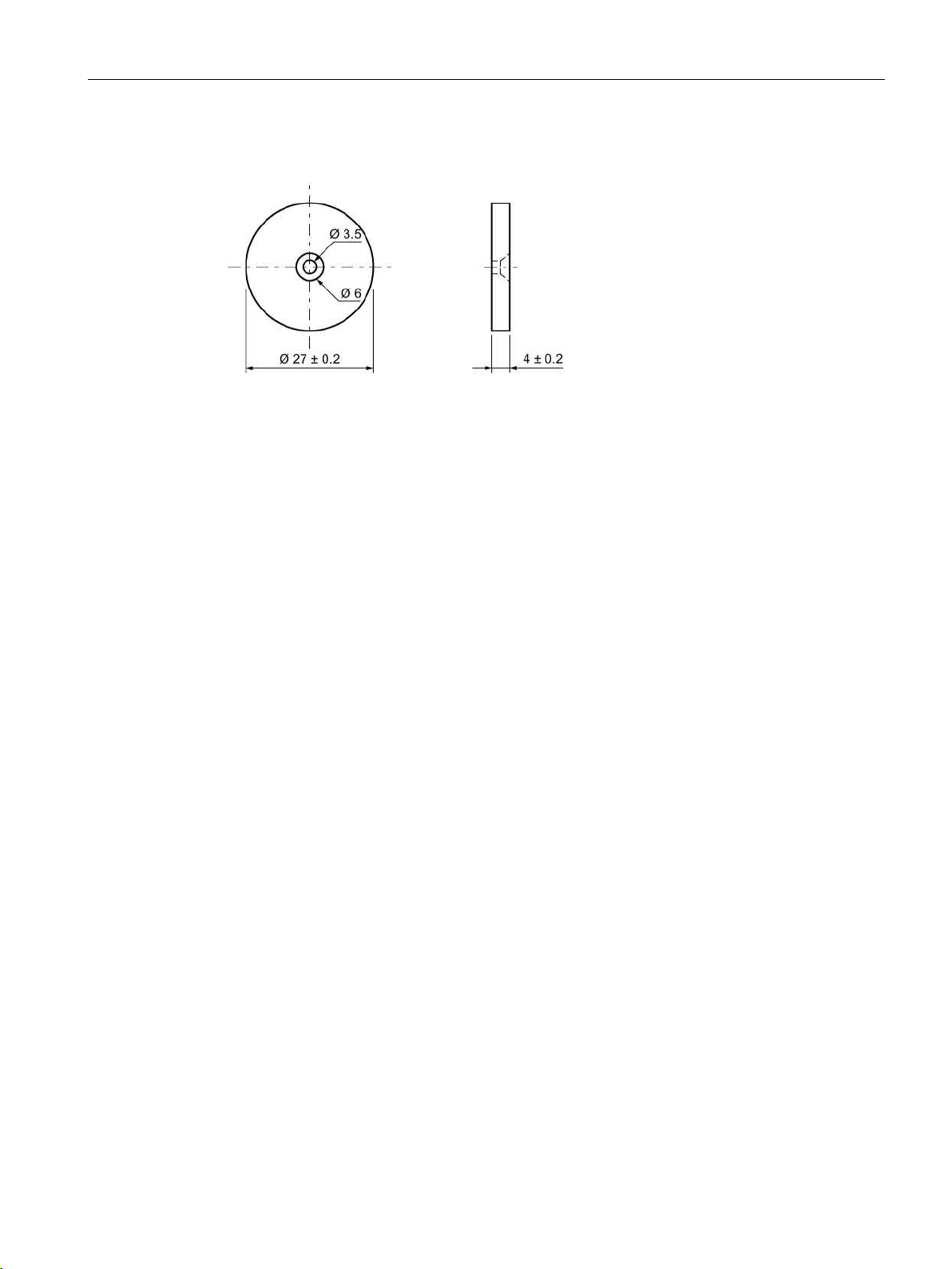
8.7.7
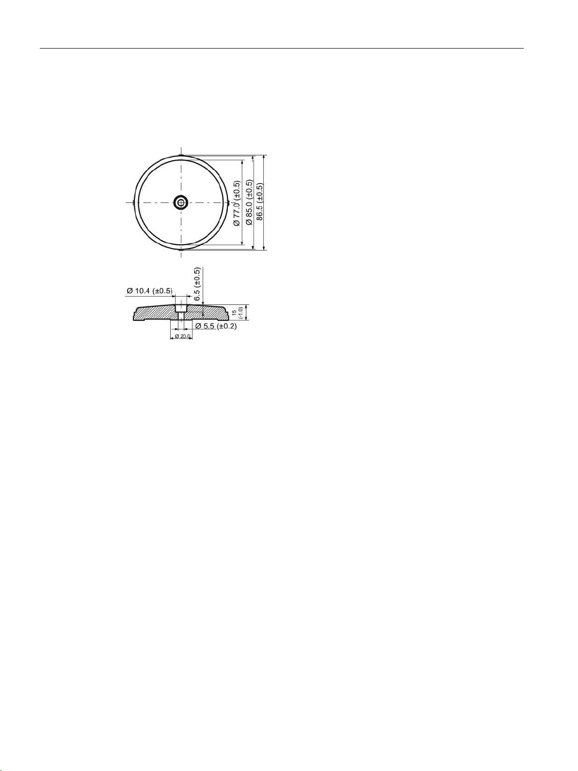
Dimension drawings
Dimensional drawing of MDS D139
8.7 MDS D139
Figure 8-16 Dimensional drawing of MDS D139
Dimensions in mm
SIMATIC RF300
306 System Manual, 07/2017, C79000-G8976-C345-07
Page 7
ISO transponder
8.8
MDS D160
8.8.1
Characteristics
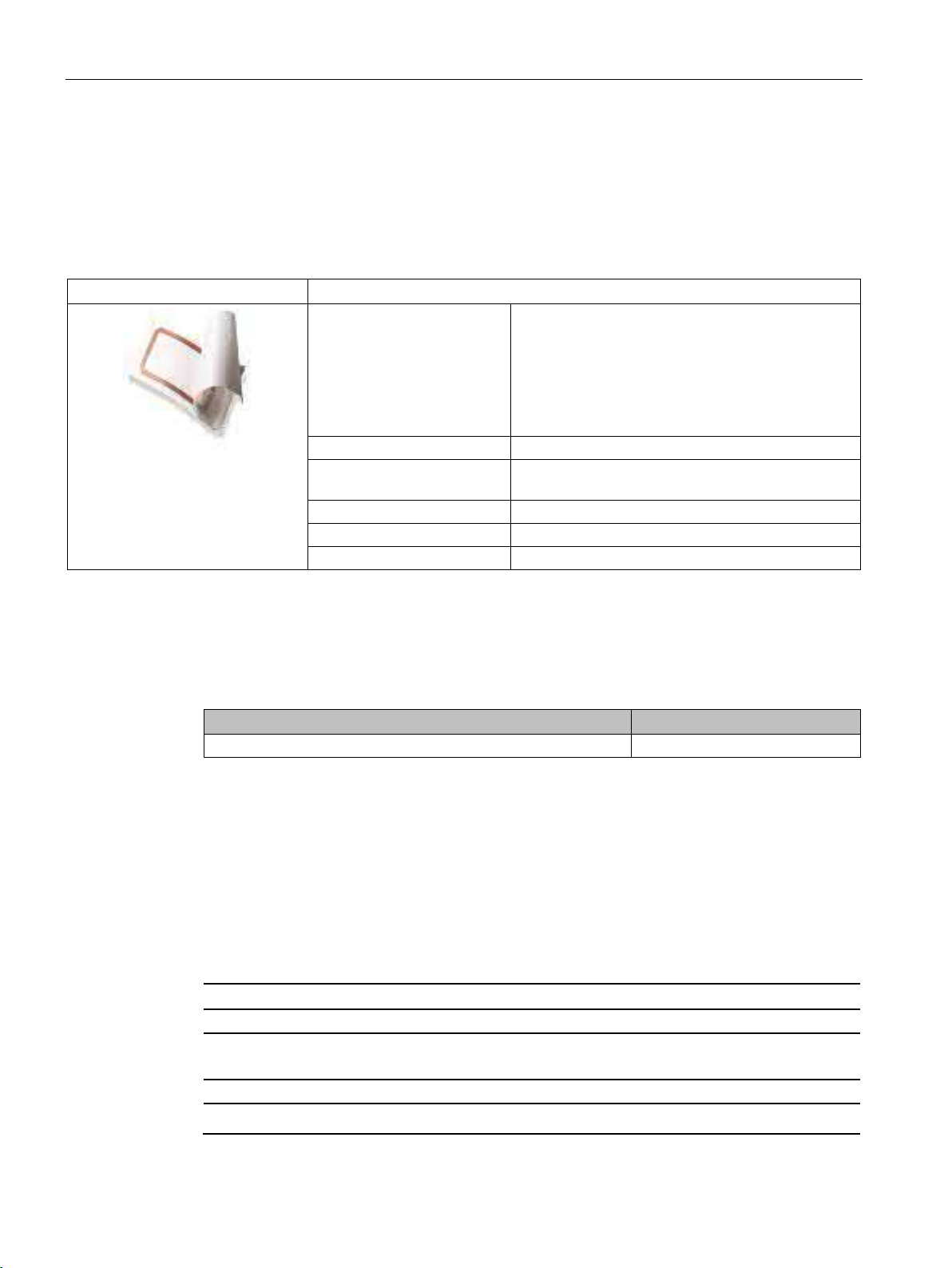
MDS D160
Characteristics
Write/read range
See section Field data of ISO transponders (MDS D) (Page 56).
Mounting on metal
Yes, with spacer
ISO standard
ISO 15693
Degree of protection
IP68/IPx9K
8.8.2
Information for RF300 compatibility
Note
Compatibility with SIMATIC RF300 depending on MLFB number
Only the MDS D160 with MLFB
8.8 MDS D160
Area of application Thanks to its rugged packaging, the MDS D160 is a transponder that
can be used under extreme environmental conditions. It is washable,
heat-resistant and resistant to all chemicals generally used in the
Memory size 112 bytes of EEPROM user memory
laundry process.
Typical applications are, for example:
• Rented work clothing
• Hotel laundry
• Surgical textiles
• Hospital clothing
• Dirt collection mats
• Clothing for nursing homes/hostels
SIMATIC RF300
System Manual, 07/2017, C79000-G8976-C345-07
6GT2600-0AB10 is compatible with SIMATIC RF300.
307
Page 8
ISO transponder
8.8.3
Ordering data
Article number
MDS D160
6GT2600-0AB10
Article number
Spacer
6GT2690-0AG00
8.8.4
Mounting on metal
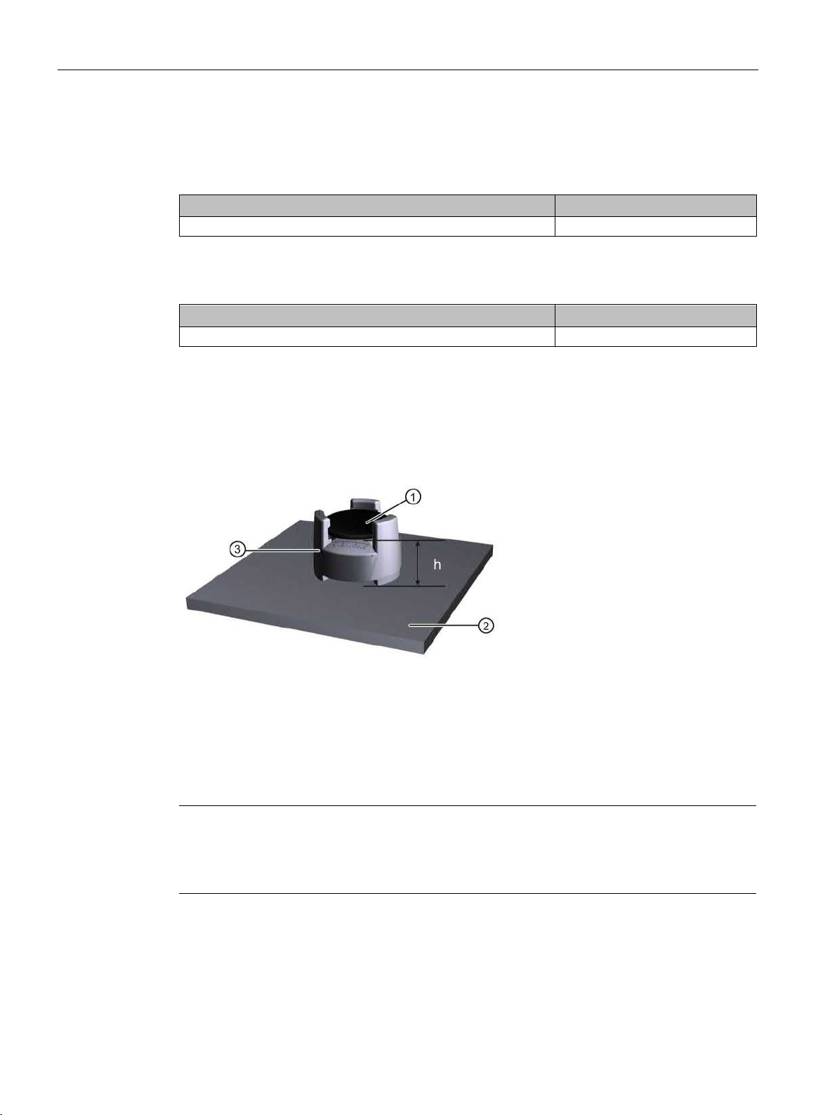
Mounting on metal
①
Transponder
②
Metal carrier
③
Spacer
h
≥ 10 mm
Note
Going below the minimum distance (h)
If the minimum distance (h) is not observed, a reduction of the fie
In critical applications, it is recommended that a test is performed.
Flush-mounting
8.8 MDS D160
Table 8- 18 Ordering data for MDS D160
Table 8- 19 Ordering data for MDS D160 accessories
Figure 8-17 Mounting the MDS D160 on metal with spacer
Flush-mounting of the MDS D160 in metal is not permitted!
SIMATIC RF300
308 System Manual, 07/2017, C79000-G8976-C345-07
ld data results.
Page 9

ISO transponder
8.8.5
Technical specifications
6GT2600-0AB10
Product type designation
SIMATIC MDS D160
Memory
Memory configuration
Read cycles (at < 40 ℃)
> 1014
Write cycles (at < 40 ℃)
> 106
Data retention time (at < 40 ℃)
> 10 years
data of ISO transponders (MDS D) (Page 56)"
MTBF (Mean Time Between Failures)
228 years
Mechanical specifications
Recommended distance to metal
≥ 10 mm
Power supply
Inductive, without battery
Permitted ambient conditions
Ambient temperature
Mechanical strength
8.8 MDS D160
Table 8- 20 Technical specifications for the MDS D160
• UID • 8 bytes
• User memory • 112 bytes EEPROM
• OTP memory • 16 bytes (EEPROM)
Write/read distance (Sg) Dependent on the reader used, see section "Field
Housing
• Material
• Color
• during write/read access
• outside the read/write field • -40 … +175 °C
• during storage • -25 to +100 ℃
• PPS
• beige
• -25 … +85 °C
• from +125 ℃: for 1000 hours, 20% reduction
of the limit distance
• at +175 ℃: 100 washing cycles tested
• at +220 ℃: Tested once for up to 30 seconds
• Isostatic pressure • 300 bar for 5 min
• Axial pressure • 1000 N for 10 s
• Radial pressure • 1000 N for 10 s
SIMATIC RF300
System Manual, 07/2017, C79000-G8976-C345-07
309
Page 10

ISO transponder
6GT2600-0AB10
cess
MDS lifespan
At least 100 wash cycles
18 ms; 6 axes; 2000 repetitions/h
10 ... 2000 Hz; 3 axes; 2.5 h
Torsion and bending load
Not permitted
Design, dimensions and weight
Dimensions (Ø x H)
16 x 3 mm
Weight
1.2 g
1)
2)
The processing instructions of the adhesive manufacturer must be observed.
Note
Regeneration time between washing cycles
The regeneration time for the MDS D160 between washing cycles must be at lea
8.8 MDS D160
Resistance to chemicals All chemicals normally used in the washing pro-
Degree of protection
• IP68
24 hours, 2 bar, +20 °C
• IPx9K
Shock according to IEC 68-2-271) 400 m/s2
Vibration according to IEC 68-2-61) 100 m/s2
Type of mounting
• Patched
• Sewn in
2)
• Glued
The values for shock and vibration are maximum values and must not be applied continuously.
SIMATIC RF300
310 System Manual, 07/2017, C79000-G8976-C345-07
st 24 hours.
Page 11
ISO transponder
8.8.6
Dimension drawings
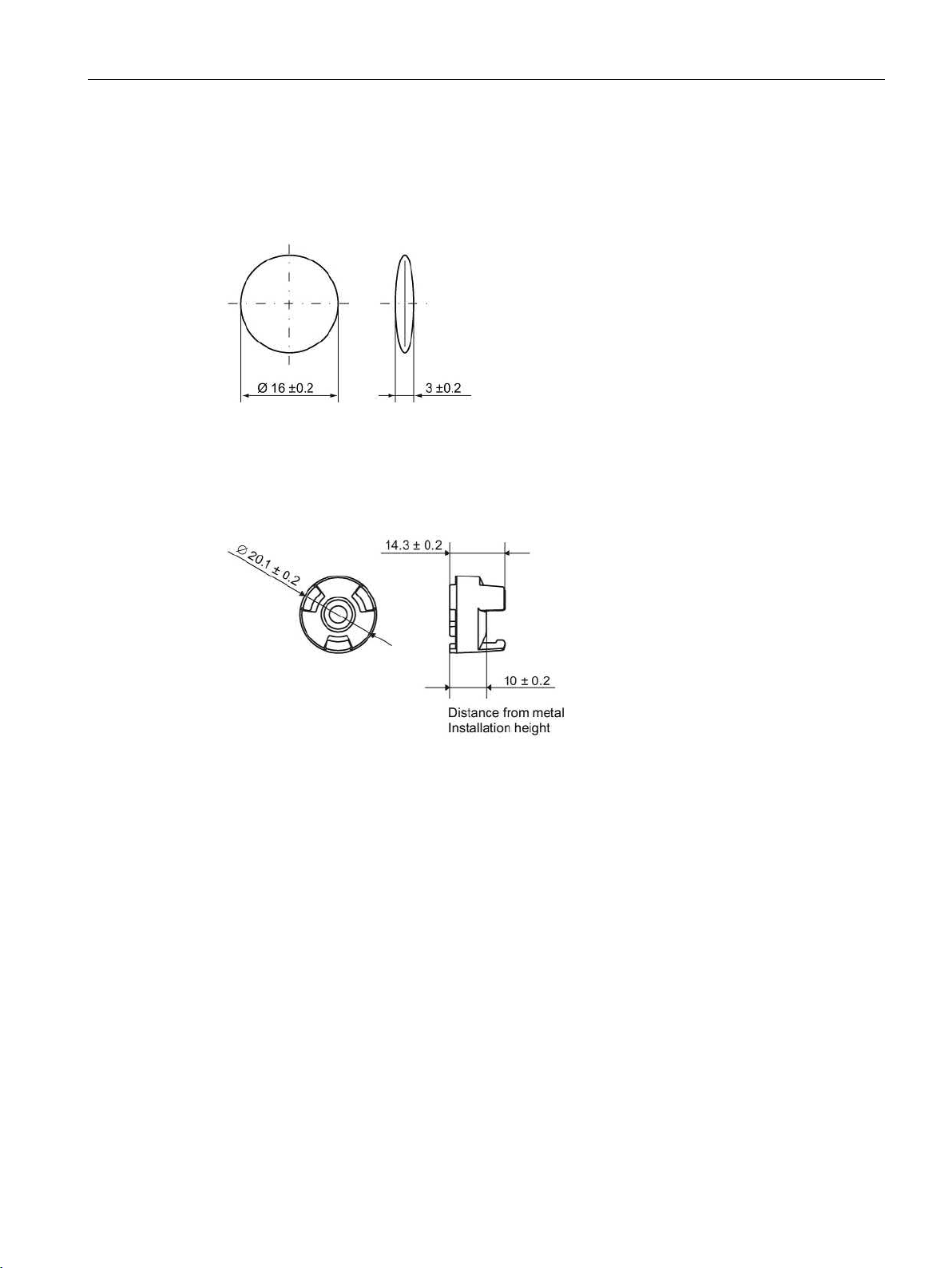
Dimensional drawing of MDS D160
Dimensions in mm
Dimensional drawing of spacer
Dimensions in mm
8.8 MDS D160
Figure 8-18 Dimensional drawing of MDS D160
Figure 8-19 Dimensional drawing of spacer
SIMATIC RF300
System Manual, 07/2017, C79000-G8976-C345-07
311
Page 12
ISO transponder
8.9
MDS D165
8.9.1
Features
MDS D165 (special version)
Characteristics
cation.
Memory size
112 bytes of EEPROM user memory
(Page 56).
Mounting on metal
Yes, with spacer
ISO standard
ISO 15693
Degree of protection
IP65
8.9.2
Ordering data
Article number
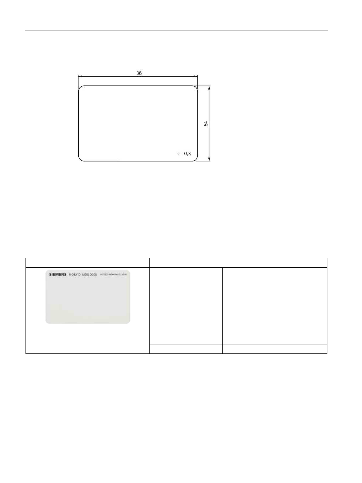
MDS D165 (special version ISO-CARD)
6GT2600-1AB00-0AX0
Type of delivery
8.9.3
Technical data
6GT2600-1AB00-0AX0
Product type designation
SIMATIC MDS D165
Memory
Memory configuration
8.9 MDS D165
Area of application The design of the transponder (self-adhesive label)
permits a variety of designs, guaranteeing optimum
dimensioning for the widest variety of applications.
From simple identification such as electronic barcode
replacement/supplementation, through warehouse
and distribution logistics, right up to product identifi-
Write/read range See section Field data of ISO transponders (MDS D)
Table 8- 21 Ordering data for MDS D165
Minimum order quantity: 1250 units (5 rolls with 250 units each)
Table 8- 22 Technical specifications for MDS D165
• UID • 8 bytes
SIMATIC RF300
312 System Manual, 07/2017, C79000-G8976-C345-07
Page 13

ISO transponder
6GT2600-1AB00-0AX0
Read cycles (at < 40 ℃)
> 1014
Write cycles (at < 40 ℃)
> 106
Data retention time (at < 40 ℃)
> 10 years
data of ISO transponders (MDS D) (Page 56)"
MTBF (Mean Time Between Failures)
228 years
Mechanical specifications
Housing
Recommended distance to metal
≥ 25 mm
Power supply
Inductive, without battery
Permitted ambient conditions
Ambient temperature
durability of the adhesive.
Degree of protection
IP65
Design, dimensions and weight
Dimensions (L x W x H)
86 x 54 x 0.3 mm
1)
The processing instructions of the adhesive manufacturer must be observed.
8.9 MDS D165
• User memory • 112 bytes EEPROM
• OTP memory • 16 bytes (EEPROM)
Write/read distance (Sg) Dependent on the reader used, see section "Field
• Material • Top • PET plastic (label
material)
• Inlay • PET plastic (carrier
material)
• Antenna • Aluminum
• Bottom • Double-sided trans-
• Color • White
• during write/read access • -25 ... +80 °C
• outside the read/write field • -25 to +80 ℃
• during storage • +20 to +30 ℃
Can be stored for 2 years, determined by the
fer adhesive on silicon paper
Weight 1 g
Type of mounting Glued with self-adhesive label 1)
SIMATIC RF300
System Manual, 07/2017, C79000-G8976-C345-07
313
Page 14
ISO transponder
8.9.4
Dimension drawing
Dimensions in mm
8.10
MDS D200
8.10.1
Features
MDS D200
Characteristics
up to product identification.
Memory size
256 bytes of EEPROM user memory
Mounting on metal
Yes, with spacer
ISO standard
15693 with Tag-it HFI technology
Degree of protection
IP67
8.10 MDS D200
Figure 8-20 Dimension drawing of MDS D165
Area of application From simple identification such as elec-
tronic barcode replacement/supplementation, through
warehouse and distribution logistics, right
Write/read range See section Field data of ISO transpond-
ers (MDS D) (Page 56).
SIMATIC RF300
314 System Manual, 07/2017, C79000-G8976-C345-07
Page 15
ISO transponder
8.10.2
Ordering data
Article number
MDS D200 (special version ISO-CARD)
6GT2600-1AD00-0AX0
Article number
(in conjunction with spacer 6GT2190-0AA00)
(not suitable for fixing directly onto metal)
8.10.3
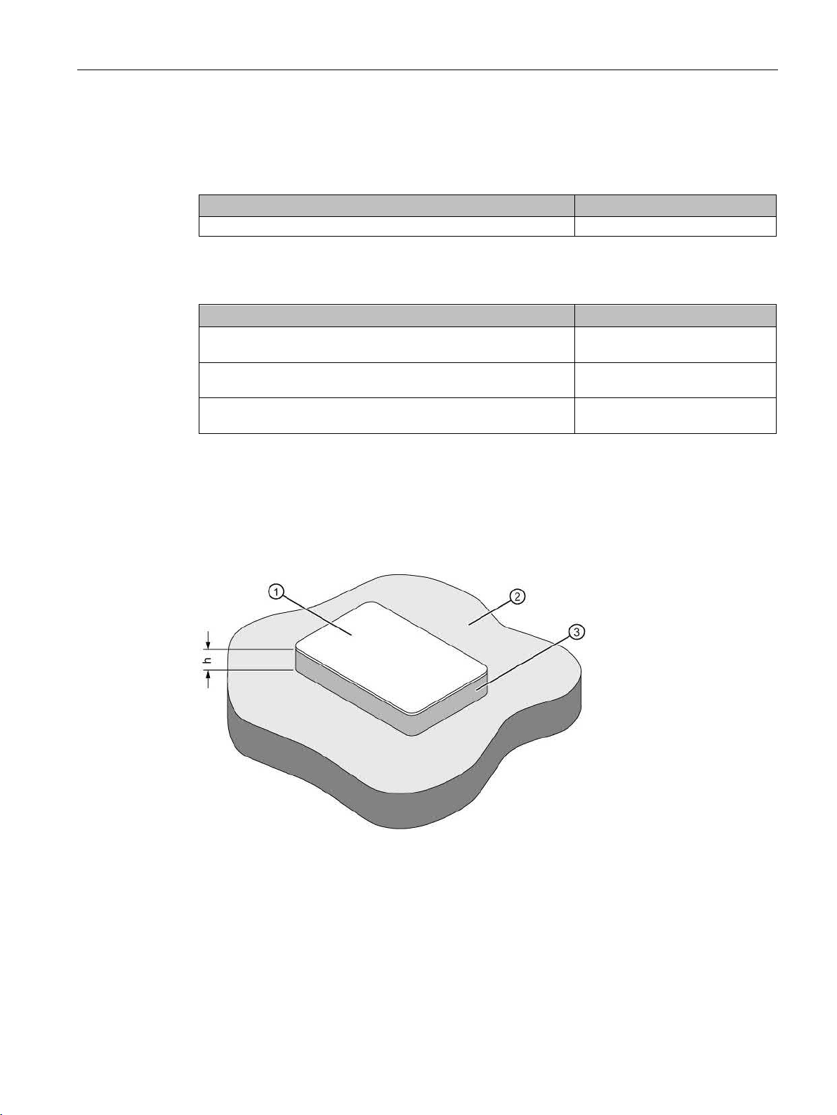
Mounting on metal
Mounting on metal
h
≥ 20 mm
①
Transponder
②
Metal
③
Non-metal
8.10 MDS D200
Table 8- 23 Ordering data for MDS D200
Table 8- 24 Ordering data for MDS D200 accessories
Spacer
(in conjunction with fixing pocket 6GT2190-0AB00)
Fixing pocket
Fixing pocket
6GT2190-0AA00
6GT2190-0AB00
6GT2390-0AA00
Figure 8-21 Mounting of the MDS D200 on metal with spacer
SIMATIC RF300
System Manual, 07/2017, C79000-G8976-C345-07
315
Page 16
ISO transponder
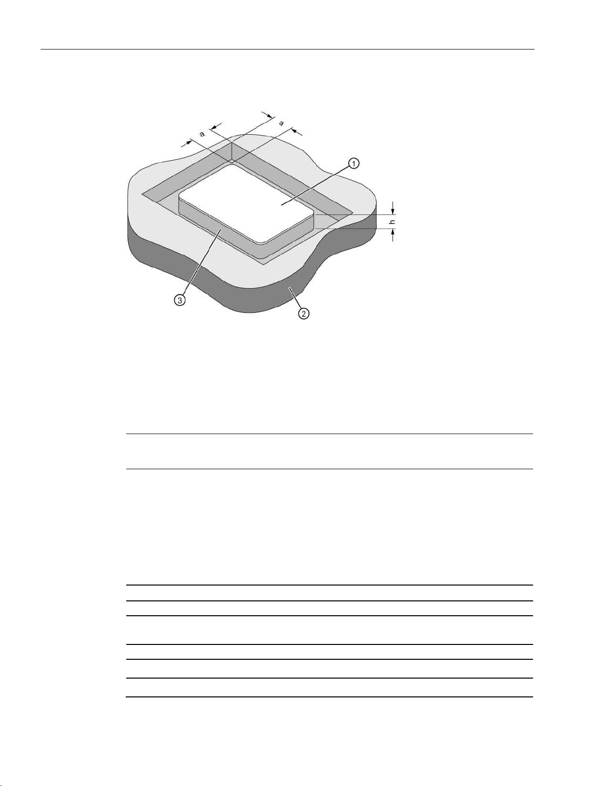
Flush-mounting
a
≥ 20 mm
h
≥ 20 mm
①
Transponder
②
Metal
③
Non-metal
Note
If the minimum guide values (h) are not observed, a reductio
8.10.4
Technical data
6GT2600-1AD00-0AX0
Product type designation
SIMATIC MDS D200
Memory
Memory configuration
8.10 MDS D200
Figure 8-22 Flush-mounting of MDS D200 in metal with spacer
n of the field data results.
Table 8- 25 Technical specifications for MDS D200
• UID • 8 bytes
• User memory • 256 bytes EEPROM
SIMATIC RF300
316 System Manual, 07/2017, C79000-G8976-C345-07
Page 17

ISO transponder
6GT2600-1AD00-0AX0
Read cycles (at < 25 ℃)
> 1014
Write cycles (at < 25 ℃)
> 106
Data retention time (at < 25 ℃)
> 10 years
data of ISO transponders (MDS D) (Page 56)"
MTBF (Mean Time Between Failures)
228 years
Mechanical specifications
Housing
Recommended distance to metal
≥ 20 mm
Power supply
Inductive, without battery
Permitted ambient conditions
Ambient temperature
Degree of protection to EN 60529
IP67
Shock-resistant to EN 60721-3-7 class 7M3
ISO 10373 / ISO 7810 1)
Vibration-resistant to EN 60721-3-7, class 7M3
ISO 10373 / ISO 7810 1)
Torsion and bending load
ISO 10373/ISO 7816-1
Design, dimensions and weight
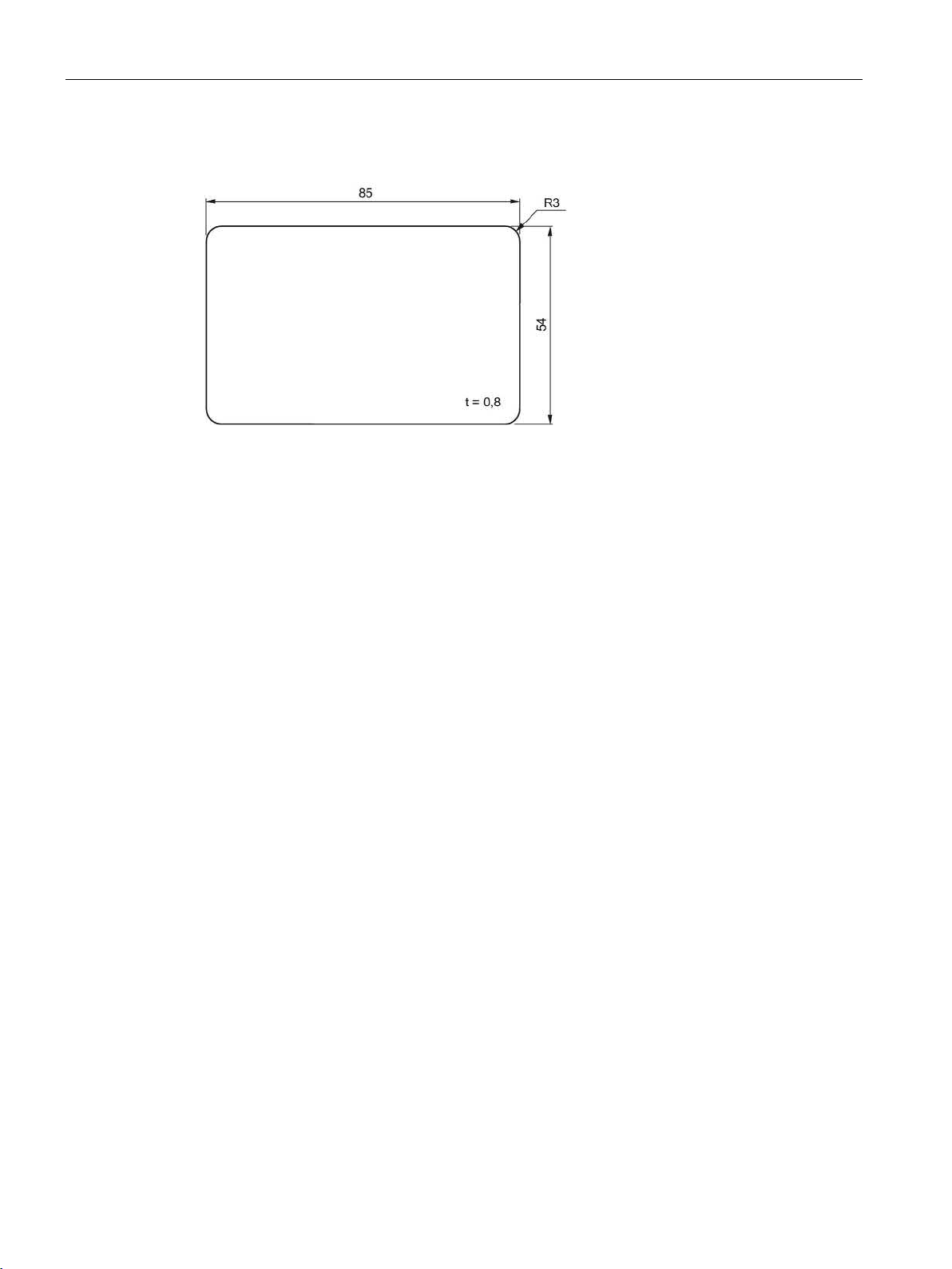
Dimensions (L x W x H)
85 x 54 x 0.8 mm
Weight
5 g
1
2)
The processing instructions of the adhesive manufacturer must be observed.
8.10 MDS D200
• OTP memory • 16 bytes (EEPROM)
Write/read distance (Sg) Dependent on the reader used, see section "Field
• Material • PET
• Color • White
• during write/read access • -20 to +60 ℃
• outside the read/write field • -20 to +60 ℃
• during storage • -20 to +60 ℃
Type of mounting
)
The values for shock and vibration are maximum values and must not be applied continuously.
• Fixing pocket
2)
• Glued
SIMATIC RF300
System Manual, 07/2017, C79000-G8976-C345-07
317
Page 18
ISO transponder
8.10.5
Dimension drawing
Dimensions in mm
8.11 MDS D261
Figure 8-23 Dimension drawing of MDS D200
SIMATIC RF300
318 System Manual, 07/2017, C79000-G8976-C345-07
Page 19
ISO transponder
8.11
MDS D261
8.11.1
Features
MDS D261
Characteristics
cation.
Memory size
256 bytes of EEPROM user memory
(Page 56).
Mounting on metal
Yes, with spacer
ISO standard
ISO 15693
Degree of protection
IP65
8.11.2
Ordering data
Article number
MDS D261
6GT2600-1AA00-0AX0
Type of delivery
8.11.3
Technical data
6GT2600-1AA01-0AX0
Product type designation
SIMATIC MDS D261
Memory
Memory configuration
8.11 MDS D261
Area of application The design of the transponder (self-adhesive label)
permits a variety of designs, guaranteeing optimum
dimensioning for the widest variety of applications.
From simple identification such as electronic barcode
replacement/supplementation, through warehouse
and distribution logistics, right up to product identifi-
Write/read range See section Field data of ISO transponders (MDS D)
Table 8- 26 Ordering data for MDS D261
Minimum order quantity: 1250 units (5 rolls with 250 units each)
SIMATIC RF300
System Manual, 07/2017, C79000-G8976-C345-07
Table 8- 27 Technical specifications of MDS D261
• UID • 8 bytes
319
Page 20

ISO transponder
6GT2600-1AA01-0AX0
Read cycles (at < 40 ℃)
> 1014
Write cycles (at < 40 ℃)
> 106
Data retention time (at < 40 ℃)
> 10 years
data of ISO transponders (MDS D) (Page 56)"
MTBF (Mean Time Between Failures)
228 years
Mechanical specifications
Housing
Recommended distance to metal
≥ 25 mm
Power supply
Inductive, without battery
Permitted ambient conditions
Ambient temperature
durability of the adhesive
Degree of protection
IP65
Design, dimensions and weight
Dimensions (L x W x H)
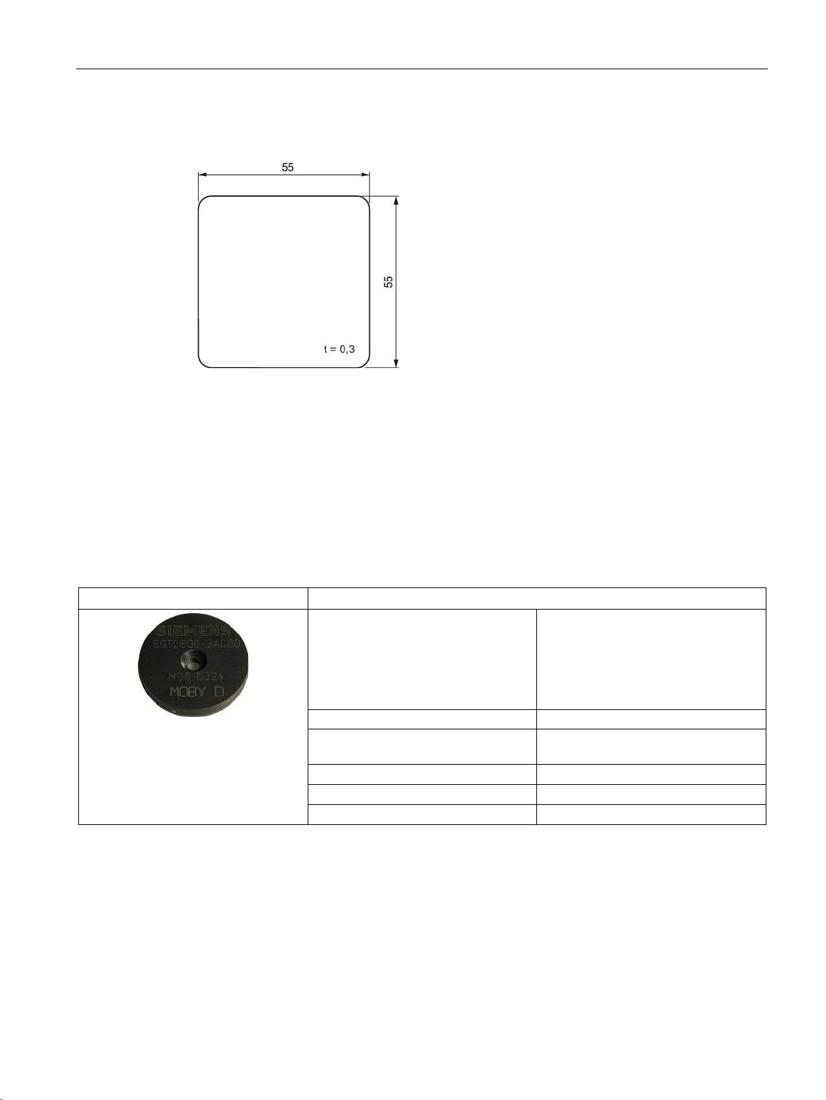
55 x 55 x 0.3 mm
1)
The processing instructions of the adhesive manufacturer must be observed.
8.11 MDS D261
• User memory • 256 bytes EEPROM
• OTP memory • 16 bytes (EEPROM)
Write/read distance (Sg) Dependent on the reader used, see section "Field
• Material • Top • PET plastic (label
material)
• Inlay • PET plastic (carrier
material)
• Antenna • Aluminum
• Bottom • Double-sided trans-
• Color • White
• during write/read access • -20 ... +60 °C
• outside the read/write field • -20 … +85 °C
• During transportation and storage • +20 to +30 ℃
Can be stored for 2 years, determined by the
fer adhesive on silicon paper
Weight 1 g
Type of mounting Glued with self-adhesive label 1)
SIMATIC RF300
320 System Manual, 07/2017, C79000-G8976-C345-07
Page 21
ISO transponder
8.11.4
Dimension drawing
Dimensions in mm
8.12
MDS D324
8.12.1
Characteristics
MDS D324
Characteristics
Memory size
992 bytes of EEPROM user memory
sponders (MDS D) (Page 56)."
Mounting on metal
Yes, with spacer
ISO standard
ISO 15693
Degree of protection
IP67; IPx9K
8.12 MDS D324
Figure 8-24 Dimension drawing of MDS D261
Area of application Production and distribution logistics
and product identification
Can also be used in harsh environ-
ments under extreme environmental
conditions (e.g. with higher temperature
load).
Write/read range See section "Field data of ISO tran-
SIMATIC RF300
System Manual, 07/2017, C79000-G8976-C345-07
321
Page 22
ISO transponder
8.12.2
Ordering data
Article number
MDS D324
6GT2600-3AC00
Article number
Spacer
6GT2690-0AK00
8.12.3
Mounting on metal
Mounting on metal
h
≥ 15 mm
8.12 MDS D324
Table 8- 28 Ordering data MDS D324
Table 8- 29 Ordering data MDS D324 accessories
SIMATIC RF300
322 System Manual, 07/2017, C79000-G8976-C345-07
Figure 8-25 Mounting the MDS D124/D324/D424/D524/E624 and RF320T on metal with spacer
Page 23
ISO transponder
Flush-mounting
h
≥ 15 mm
a
≥ 25 mm
Note
Going below the distances
If the distances (a and h) are not observed, a reduction of the field data results. It is possible
to mount the MDS with metal screws (M3 counters
impact on the range.
8.12.4
Technical specifications
6GT2600-3AC00
Product type designation
SIMATIC MDS D324
Memory
Memory configuration
Read cycles (at < 40 ℃)
> 1014
Write cycles (at < 40 ℃)
> 106
Data retention time (at < 40 ℃)
> 10 years
8.12 MDS D324
Figure 8-26 Flush-mounting of the MDS D124/D324/D424/D524/E624 and RF320T in metal with
spacer
unk head screws). This has no tangible
Table 8- 30 Technical specifications of MDS D324
• UID • 8 bytes
• User memory • 992 bytes EEPROM
• OTP memory • 16 bytes (EEPROM)
SIMATIC RF300
System Manual, 07/2017, C79000-G8976-C345-07
323
Page 24

ISO transponder
6GT2600-3AC00
data of ISO transponders (MDS D) (Page 56)"
MTBF (Mean Time Between Failures)
228 years
Mechanical specifications
Housing
Recommended distance to metal
≥ 15 mm
Power supply
Inductive, without battery
Permitted ambient conditions
Ambient temperature
Shock according to EN 60721-3-7 Class 7M31)
1000 m/s2
Vibration according to EN 60721-3-7 Class 7M31)
200 m/s2
Torsion and bending load
Not permitted
Design, dimensions and weight
Dimensions (Ø x H)
27 x 4 mm
Weight
5 g
1)
2
3)
The processing instructions of the adhesive manufacturer must be observed.
8.12 MDS D324
Write/read distance (Sg) Dependent on the reader used, see section "Field
• Material • Epoxy resin
• Color • Black
• during write/read access • -25 to +125 ℃
• outside the read/write field • -40 to +140 ℃
• during storage • -40 to +140 ℃
Degree of protection to EN 60529
• IP67
• IPx9K
Type of mounting
• 1 x M3 screw
2)
≤ 1 Nm
• Glued 3)
The values for shock and vibration are maximum values and must not be applied continuously.
) To prevent it loosening during operation, secure the screw with screw locking varnish.
SIMATIC RF300
324 System Manual, 07/2017, C79000-G8976-C345-07
Page 25
ISO transponder
8.12.5
Dimension drawing
8.12 MDS D324
Figure 8-27 Dimension drawing of MDS D324
All dimensions in mm
SIMATIC RF300
System Manual, 07/2017, C79000-G8976-C345-07
325
Page 26
ISO transponder
8.13
MDS D339
8.13.1
Characteristics
MDS D339
Characteristics
(Page 56).
Mounting on metal
Yes, with spacer
ISO standard
ISO 15693
Degree of protection
IP68/IPx9K
8.13.2
Ordering data
Article number
MDS D339
6GT2600-3AA10
Article number
Spacer
6GT2690-0AA00
(Ø x H): 22 x 60 mm
(Ø x H): 22 x 47 mm
8.13 MDS D339
Area of application Applications in production automation with high
temperature demands (up to +220 °C)
Typical application areas:
• Paintshops and their preparatory treatments
• Primer coat, electrolytic dip area, cataphoresis
with the associated drying furnaces
• Top coat area with drying furnaces
• Washing areas at temperatures > 85 °C
• Other applications with higher temperatures
Memory size 992 bytes of EEPROM user memory
Write/read range See section Field data of ISO transponders (MDS D)
Table 8- 31 Ordering data for MDS D339
Table 8- 32 Ordering data for MDS D339 accessories
Quick change holder
Quick change holder
6GT2690-0AH00
6GT2690-0AH10
SIMATIC RF300
326 System Manual, 07/2017, C79000-G8976-C345-07
Page 27
ISO transponder
8.13.3
Mounting on metal
Mounting on metal
h
≥ 30 mm
Flush-mounting
h
≥ 30 mm
a
≥ 100 mm
8.13 MDS D339
Direct mounting of the MDS D139/D339 on metal is not allowed. A distance of ≥ 30 mm is
recommended. This can be achieved using spacers (see "Ordering data (Page 326)").
Figure 8-28 Mounting the MDS D139/D339 on metal with spacer
It is possible to mount the MDS D139/D339 in metal. With large antennas, for example ANT
D5, this leads to a reduction of ranges.
Figure 8-29 Flush-mounting of the MDS D139/D339 in metal with spacer
SIMATIC RF300
System Manual, 07/2017, C79000-G8976-C345-07
327
Page 28

ISO transponder
Note
Going below the distances
If the distances (a and h) are not observed, a reduction of the field data results. It is possible
to mount the MDS with
recommended that a test is performed in critical applications.
8.13.4
Cleaning the mobile data memory
Note
Do not clean the transponder with mechanical tools, sand
cleaning methods result in damage to the transponder.
Clean the transponder only with the cleaning agents listed in the section "Chemical
resistance of the MDS".
8.13.5
Technical specifications
6GT2600-3AA10
Product type designation
SIMATIC MDS D339
Memory
Memory configuration
Data retention time (at < 40 ℃)
> 10 years
MTBF (Mean Time Between Failures)
228 years
Mechanical specifications
Housing
8.13 MDS D339
metal screws (M5). This has no tangible impact on the range. It is
-blasting or pressure hose. These
Table 8- 33 Technical specifications of MDS D339
• UID • 8 bytes
• User memory • 992 bytes EEPROM
• OTP memory • 16 bytes (EEPROM)
Read cycles (at < 40 ℃) > 1014
Write cycles (at < 40 ℃) > 106
Write/read distance (Sg) Dependent on the reader used, see section "Field
data of ISO transponders (MDS D) (Page 56)"
• Material • PPS
SIMATIC RF300
328 System Manual, 07/2017, C79000-G8976-C345-07
Page 29

ISO transponder
6GT2600-3AA10
Recommended distance to metal
≥ 30 mm
Power supply
Inductive, without battery
Permitted ambient conditions
Ambient temperature
Shock according to EN 60721-3-7 Class 7M31)
500 m/s2
Vibration according to EN 60721-3-7 Class 7M31)
200 m/s2
Torsion and bending load
Not permitted
Design, dimensions and weight
Dimensions (Ø x H)
85 x 15 mm
Weight
50 g
1.5 Nm
1
2)
ing the MDS in high temperatures (expansion coefficient).
8.13 MDS D339
• Color • Black
• during write/read access • -25 to +100 ℃
• outside the read/write field • -40 to +220 ℃
• from +125 ℃: 20% reduction in the limit dis-
tance
• at +200 ℃: Tested up to 5000 hours or
6000 cycles
• at +220 ℃: Tested up to 2000 hours or
2000 cycles
• during storage • -40 to +100 ℃
Degree of protection to EN 60529
• IP68
2 hours, 2 bar, +20 °C
• IPx9K
steam jet: 150 mm; 10 to 15 l/min; 100 bar; 75
°C
Type of mounting 1 x M5 screw 2)
The values for shock and vibration are maximum values and must not be applied continuously.
For mounting with the spacer (6GT2690-0AA00), use a stainless steel M5 screw to avoid damag-
SIMATIC RF300
System Manual, 07/2017, C79000-G8976-C345-07
329
Page 30
ISO transponder
8.13.6
Use of the MDS D339 in hazardous areas
Identification
WARNING
Gefahr durch elektrostatische Entladungen
Potential electrostatic charging hazard
Danger potentiel de charges électrostatiques
8.13 MDS D339
The MDS D339 mobile data memory is classed as a piece of simple, electrical equipment
and can be operated in Protection Zone 2, Device Group II, Category 3G.
The following requirements of the 94/9/EC directive are met:
● EN 60079-0:2006
● EN 60079-15:2005
● EN 61241-0:2006
● EN 61241-1:2004
II 3 G Ex nA II T6
Ii 3 D Ex tD A22 IP68 T 210°C
KEMA 09 ATEX 0133 X
SIMATIC RF300
330 System Manual, 07/2017, C79000-G8976-C345-07
Page 31

ISO transponder
Note
Installations- und Betriebsbedingungen für den Ex-Schutzbereich:
a) Der Einsatz des Gerätes in der Nähe von stark ladungserzeugenden Prozessen ist
untersagt.
b) Das Gerät ist mechanisch geschützt zu montieren.
c) Die Montage muss auf eine
d) Die Reinigung darf nur mit feuchtem Tuch erfolgen.
Installation and operating conditions for hazardous areas:
a) Use of the equipment in the vicinity of processes generating high charges is not allowed.
b) Th
c) Installation must be performed on a grounded and conductive mounting surface.
d) Cleaning only with a wet cloth
Conditions d'installation et de mise en oeuvre pour la zone de protection Ex :
a)
b) L'appareil doit être monté de manière à être protégé mécaniquement.
c) Le montage doit être effectué sur un socle conducteur mis à la terre.
d) Nettoyage uniquement
8.13 MDS D339
m geerdeten, leitenden Untergrund erfolgen.
e equipment must be mechanically protected when installed.
L'utilisation de l'appareil près de processus générant de fortes charges est interdite.
avec un chiffon humide
SIMATIC RF300
System Manual, 07/2017, C79000-G8976-C345-07
331
Page 32

ISO transponder
8.13.7
Dimensional drawing
MDS D339
8.13 MDS D339
Figure 8-30 Dimension drawing of the MDS D339
Dimensions in mm
SIMATIC RF300
332 System Manual, 07/2017, C79000-G8976-C345-07
Page 33

ISO transponder
8.14
MDS D400
8.14.1
Features
MDS D400
Characteristics
tion logistics right through to product identification.
(Page 56)"
Mounting on metal
Yes, with spacer
ISO standard
ISO 15693
Degree of protection
IP67
8.14.2
Ordering data
Article number
MDS D400
6GT2600-4AD00
Article number
(in conjunction with fixing pocket 6GT2190-0AB00)
(in conjunction with spacer 6GT2190-0AA00)
(not suitable for fixing directly onto metal)
8.14 MDS D400
Area of application
Memory size 2000 bytes of FRAM user memory
Write/read range See section "Field data of ISO transponders (MDS D)
Table 8- 34 Ordering data of MDS D400
Simple identification such as electronic barcode replacement/supplements, from warehouse and distribu-
Table 8- 35 Ordering data of MDS D400 accessories
Spacer
Fixing pocket
Fixing pocket
SIMATIC RF300
System Manual, 07/2017, C79000-G8976-C345-07
6GT2190-0AA00
6GT2190-0AB00
6GT2390-0AA00
333
Page 34

ISO transponder
8.14.3
Mounting on metal
Mounting on metal
h
≥ 20 mm
①
Transponder
②
Metal
③
Non-metal
8.14 MDS D400
It is possible to mount the MDS D400 on metal.
Figure 8-31 Mounting of the MDS D400 on metal with spacer
SIMATIC RF300
334 System Manual, 07/2017, C79000-G8976-C345-07
Page 35

ISO transponder
Flush-mounted in metal
a
≥ 20 mm
h
≥ 20 mm
①
Transponder
②
Metal
③
Non-metal
Note
If the minimum guide values (h) are not observed, th
data.
8.14.4
Technical specifications
6GT2600-4AD00
Product type designation
SIMATIC MDS D400
Memory
Memory configuration
8.14 MDS D400
Figure 8-32 Flush-mounting of MDS D400 in metal with spacer
is will result in a reduction of the field
Table 8- 36 Technical specifications for MDS D400
• UID • 8 bytes
• User memory • 2000 bytes FRAM
SIMATIC RF300
System Manual, 07/2017, C79000-G8976-C345-07
335
Page 36

ISO transponder
6GT2600-4AD00
Read cycles (at < 25 ℃)
> 1012
Write cycles (at < 25 ℃)
> 1012
Data retention time (at < 25 ℃)
> 10 years
data of ISO transponders (MDS D) (Page 56)"
MTBF (Mean Time Between Failures)
228 years
Mechanical specifications
Housing
Recommended distance to metal
≥ 20 mm
Power supply
Inductive, without battery
Permitted ambient conditions
Ambient temperature
Degree of protection to EN 60529
IP67
Vibration-resistant to EN 60721-3-7, class 7M3
ISO 10373 / ISO 7810 1)
Torsion and bending load
ISO 10373/ISO 7816-1
Design, dimensions and weight
Dimensions (L x W x H)
85 x 54 x 0.8 mm
Weight
5 g
1)
2)
The processing instructions of the adhesive manufacturer must be observed.
8.14 MDS D400
• OTP memory • 16 bytes FRAM
Write/read distance (Sg) Dependent on the reader used, see section "Field
• Material • PVC
• Color • White
• during write/read access • -20 to +60 ℃
• outside the read/write field • -20 to +60 ℃
• during storage • -20 to +60 ℃
Type of mounting
• Fixing lug
2)
• Glued
The values for vibration are maximum values and must not be applied continuously.
SIMATIC RF300
336 System Manual, 07/2017, C79000-G8976-C345-07
Page 37

ISO transponder
8.14.5
Dimension drawing
8.14 MDS D400
Figure 8-33 Dimensional drawing MDS D400 (dimensions in mm)
SIMATIC RF300
System Manual, 07/2017, C79000-G8976-C345-07
337
Page 38

ISO transponder
8.15
MDS D421
8.15.1
Characteristics
MDS D421
Characteristics
lems.
Memory size
2000 bytes of FRAM user memory
(Page 56)"
Mounting on metal
Yes, flush-mounted in metal
ISO standard
ISO 15693
Degree of protection
IP67/IPx9K
8.15.2
Ordering data
Article number
MDS D421
6GT2600-4AE00
8.15 MDS D421
Area of application The MDS D421 is designed for tool coding in accordance
with DIN 69873.
Write/read range See section "Field data of ISO transponders (MDS D)
It can be used wherever small data carriers and exact positioning are required, e.g. tool identification, workpiece holders.
The rugged housing of the MDS D421 means that it can
also be used in a harsh industrial environment without prob-
Table 8- 37 Ordering data of MDS D421
SIMATIC RF300
338 System Manual, 07/2017, C79000-G8976-C345-07
Page 39

ISO transponder
8.15.3
Mounting on metal
Mounting on metal
Flush-mounting
8.15 MDS D421
Figure 8-34 Mounting of MDS D421/D521/E623 on metal
Figure 8-35 Mounting of MDS D421/D521/E623 in metal
SIMATIC RF300
System Manual, 07/2017, C79000-G8976-C345-07
339
Page 40

ISO transponder
Flush-mounting of the MDS in metal with tools
b1
0.5 x 45°
b2
0.3 x 45° or R0.3
d1
10 (-0.04... -0.13)
d2
10 (+0.09... 0)
t1
4.5 (-0 ... -0.1)
t2
4.6 (+0.2 ... 0)
All dimensions in mm
Note
Installation instruction
The MDS s
contour.
The mounting instructions of the MDS and the conditions associated with the application
(e.g. peripheral speed, temperature, and use of coolant) must be observed during
installation.
Mounting information for adhesion
8.15 MDS D421
Figure 8-36 Flush-mounting of MDS D421/D521/E623 in metal with tools
hould not protrude out of the locating hole; it must be flush with the outside
● Drill installation hole
● The adhesive surfaces must be dry, free from dust, oil, stripping agents and other
impurities
● Apply adhesive according to the manufacturer's processing instructions
● Press in transponder using your fingers; with antenna side to the outside (see figure
above)
● Remove residues of adhesive
the
● Allow to cure according to the manufacturer's instructions
● Flush-mounting of the transponder in metal with tools
SIMATIC RF300
340 System Manual, 07/2017, C79000-G8976-C345-07
Page 41

ISO transponder
Installation examples
8.15.4
Technical specifications
6GT2600-4AE00
Product type designation
SIMATIC MDS D421
Memory
Memory configuration
Read cycles (at < 40 ℃)
> 1012
Write cycles (at < 40 ℃)
> 1012
Data retention time (at < 40 ℃)
> 10 years
data of ISO transponders (MDS D) (Page 56)"
MTBF (Mean Time Between Failures)
228 years
Mechanical specifications
Housing
8.15 MDS D421
Figure 8-37 Installation example of MDS D421/D521/E623 in a steep cone
Figure 8-38 Installation example of MDS D421/D521/E623 in a stud bolt
Table 8- 38 Technical specifications for the MDS D421
• UID • 8 bytes
• User memory • 2000 bytes FRAM
• OTP memory • 16 bytes FRAM
Write/read distance (Sg) Dependent on the reader used, see section "Field
• Material • Epoxy resin
• Color • Black
SIMATIC RF300
System Manual, 07/2017, C79000-G8976-C345-07
341
Page 42

ISO transponder
6GT2600-4AE00
Recommended distance to metal
≥ 0 mm
Power supply
Inductive, without battery
Permitted ambient conditions
Ambient temperature
Shock according to EN 60721-3-7 Class 7M31)
1000 m/s2
Vibration according to EN 60721-3-7 Class 7M31)
200 m/s2
Torsion and bending load
Not permitted
Design, dimensions and weight
Dimensions (Ø x H)
10 x 4.5 mm
Weight
Approx. 1 g
Type of mounting
Glued 2)
1)
2)
The processing instructions of the adhesive manufacturer must be observed.
8.15.5
Dimension drawing
8.15 MDS D421
• during write/read access • -25 to +85 ℃
• outside the read/write field • -40 to +100 ℃
• during storage • -40 to +100 ℃
Degree of protection to EN 60529
The values for shock and vibration are maximum values and must not be applied continuously.
• IP67
• IPx9K
steam jet: 150 mm; 10 to 15 l/min; 100 bar; 75
°C
Figure 8-39 Dimension drawing of MDS D421
All dimensions in mm
SIMATIC RF300
342 System Manual, 07/2017, C79000-G8976-C345-07
Page 43

ISO transponder
8.16
MDS D422
8.16.1
Characteristics
MDS D422
Characteristics
containers
Memory size
2000 bytes of FRAM user memory
(Page 56).
Mounting on metal
Yes
ISO standard
ISO 15693
Degree of protection
IP68
8.16.2
Ordering data
Article number
unit
8.16 MDS D422
Area of application
Write/read range See section "Field data of ISO transponders (MDS D)
Identification of metallic workpiece holders, workpieces or
Table 8- 39 Ordering data of MDS D422
MDS D422
A screw-in aid is included in the scope of supply per packaging
6GT2600-4AF00
SIMATIC RF300
System Manual, 07/2017, C79000-G8976-C345-07
343
Page 44

ISO transponder
8.16.3
Mounting in metal
Flush-mounting
Mounting information for screws
Mounting information for adhesion
8.16.4
Technical specifications
6GT2600-4AF00
Product type designation
SIMATIC MDS D422
Memory
Memory configuration
8.16 MDS D422
Figure 8-40 Mounting of MDS D422 in metal
You can screw the transponder into a pre-drilled threaded hole using the screw-in aid.
● Drill installation hole
● The adhesive surfaces must be dry, free from dust, oil, stripping agents and other
impurities
● Apply adhesive according to the manufacturer's processing instructions
● Press in MDS D422 using your fingers; with antenna to the outside
● Remove residues of adhesive
● Allow to cure according to the manufacturer's instructions
● Flush-mounting of MDS D422 in metal with tools
Table 8- 40 Technical specifications for the MDS D422
SIMATIC RF300
344 System Manual, 07/2017, C79000-G8976-C345-07
Page 45

ISO transponder
6GT2600-4AF00
Read cycles (at < 40 ℃)
> 1012
Write cycles (at < 40 ℃)
> 1012
Data retention time (at < 40 ℃)
> 10 years
data of ISO transponders (MDS D) (Page 56)"
MTBF (Mean Time Between Failures)
285 years
Mechanical specifications
Housing
Recommended distance to metal
≥ 0 mm
Power supply
Inductive, without battery
Permitted ambient conditions
Ambient temperature
2 hours, 2 bar, +20 °C
Shock according to EN 60721-3-7 Class 7M31)
500 m/s2
Vibration according to EN 60721-3-7 Class 7M31)
200 m/s2
Torsion and bending load
Not permitted
Design, dimensions and weight
Dimensions (Ø x H)
20 x 6 mm
Weight
13 g
1)
2)
The processing instructions of the adhesive manufacturer must be observed.
8.16 MDS D422
• UID • 8 bytes
• User memory • 2000 bytes FRAM
• OTP memory • 16 bytes FRAM
Write/read distance (Sg) Dependent on the reader used, see section "Field
• Material • Plastic PA 6.6 GF; brass nickel plated
• Color • Black/silver
• during write/read access • -25 to +85 ℃
• outside the read/write field • -40 to +100 ℃
• during storage • -40 to +100 ℃
Degree of protection to EN 60529 IP68
Type of mounting
• Glued
2)
• 1 x transponder thread M20
≤ 1 Nm
The values for shock and vibration are maximum values and must not be applied continuously.
SIMATIC RF300
System Manual, 07/2017, C79000-G8976-C345-07
345
Page 46

ISO transponder
8.16.5
Dimension drawing
Dimensions in mm
8.17
MDS D423
8.17.1
Characteristics
MDS D423
Characteristics
pieces or containers, production automation
D) (Page 56)"
ISO standard
ISO 15693
8.17.2
Ordering data
Article number
MDS D423
6GT2600-4AA00
Article number
Fixing hood RF330T / MDS D423
6GT2690-0AE00
8.17 MDS D423
Figure 8-41 Dimensional drawing of MDS D422
Area of application
Identification of metallic workpiece holders, work-
Memory size 2000 bytes of FRAM user memory
Write/read range See section "Field data of ISO transponders (MDS
Mounting on metal Yes, flush-mounted in metal
Degree of protection IP68/IPx9K
Table 8- 41 Ordering data of MDS D423
Table 8- 42 Ordering data of MDS D423 accessories
SIMATIC RF300
346 System Manual, 07/2017, C79000-G8976-C345-07
Page 47

ISO transponder
8.17.3
Mounting on metal
Mounting on metal
Flush-mounted in metal
a
≥ 10 mm
8.17 MDS D423
Direct mounting of the MDS D423 on metal is possible.
Figure 8-42 Mounting the MDS D423 on metal
It is possible to mount the MDS D423 in metal.
Figure 8-43 Flush-mounting of the MDS D423 in metal with 10 mm clearance
SIMATIC RF300
System Manual, 07/2017, C79000-G8976-C345-07
347
Page 48

ISO transponder
Note
Reduction of the write/read range
Note that when the device is flush
mm, the write/read range is significantly reduced.
8.17.4
Technical specifications
6GT2600-4AA00
Product type designation
SIMATIC MDS D423
Memory
Memory configuration
Read cycles (at < 40 ℃)
> 1012
Write cycles (at < 40 ℃)
> 1012
Data retention time (at < 40 ℃)
> 10 years
data of ISO transponders (MDS D) (Page 56)"
MTBF (Mean Time Between Failures)
228 years
Mechanical specifications
Housing
8.17 MDS D423
Figure 8-44 Flush-mounting of the MDS D423 in metal without clearance
-mounted in metal without a surrounding clearance ≥ 10
Table 8- 43 Technical specifications of MDS D423
• UID • 8 bytes
• User memory • 2000 bytes FRAM
• OTP memory • 16 bytes FRAM
Write/read distance (Sg) Dependent on the reader used, see section "Field
• Material • Plastic PPS
SIMATIC RF300
348 System Manual, 07/2017, C79000-G8976-C345-07
Page 49

ISO transponder
6GT2600-4AA00
Recommended distance to metal
≥ 0 mm
Power supply
Inductive, without battery
Permitted ambient conditions
Ambient temperature
Shock according to EN 60721-3-7 Class 7M31)
500 m/s2
Vibration according to EN 60721-3-7 Class 7M31)
200 m/s2
Torsion and bending load
Not permitted
Design, dimensions and weight
Dimensions (Ø x H)
30 x 8 mm
Weight
15 g
≤ 1 Nm
1)
2
) To prevent it loosening during operation, secure the screw with screw locking varnish.
8.17 MDS D423
• Color • Black
• during write/read access • -25 to +85 ℃
• outside the read/write field • -40 to +100 ℃
• during storage • -40 to +100 ℃
Degree of protection to EN 60529
• IP68
2 hours, 2 bar, +20 °C
• IPx9K
steam jet: 150 mm; 10 to 15 l/min; 100 bar; 75
°C
Pressure resistance
• Low pressure resistant
vacuum dryer: up to 20 mbar
• High pressure resistant
(see degree of protection IPx9K)
Type of mounting 1 x M4 screw 2)
The values for shock and vibration are maximum values and must not be applied continuously.
SIMATIC RF300
System Manual, 07/2017, C79000-G8976-C345-07
349
Page 50

ISO transponder
8.17.5
Dimensional drawing
Dimensions in mm
8.18
MDS D424
8.18.1
Characteristics
MDS D424
Characteristics
without problem
Memory size
2000 bytes of FRAM user memory
D) (Page 56)."
Mounting on metal
Yes, with spacer
ISO standard
ISO 15693
Degree of protection
IP67; IPx9K
8.18 MDS D424
Figure 8-45 Dimension drawing for MDS D423
Area of application Production and distribution logistics as well as in
Write/read range See section "Field data of ISO transponders (MDS
assembly and production lines,
can also be used in a harsh industrial environment
SIMATIC RF300
350 System Manual, 07/2017, C79000-G8976-C345-07
Page 51

ISO transponder
8.18.2
Ordering data
Article number
MDS D424
6GT2600-4AC00
Article number
Spacer
6GT2690-0AK00
8.18.3
Mounting on metal
Mounting on metal
h
≥ 15 mm
8.18 MDS D424
Table 8- 44 Ordering data of MDS D424
Table 8- 45 Ordering data of MDS D424 accessories
SIMATIC RF300
System Manual, 07/2017, C79000-G8976-C345-07
Figure 8-46 Mounting the MDS D124/D324/D424/D524/E624 and RF320T on metal with spacer
351
Page 52

ISO transponder
Flush-mounting
h
≥ 15 mm
a
≥ 25 mm
Note
Going below the distances
If the distances (a and h) are not observed,
to mount the MDS with metal screws (M3 countersunk head screws). This has no tangible
impact on the range.
8.18.4
Technical specifications
6GT2600-4AC00
Product type designation
SIMATIC MDS D424
Memory
Memory configuration
Read cycles (at < 40 ℃)
> 1012
Write cycles (at < 40 ℃)
> 1012
Data retention time (at < 40 ℃)
> 10 years
8.18 MDS D424
Figure 8-47 Flush-mounting of the MDS D124/D324/D424/D524/E624 and RF320T in metal with
spacer
a reduction of the field data results. It is possible
Table 8- 46 Technical specifications for the MDS D424
• UID • 8 bytes
• User memory • 2000 bytes FRAM
• OTP memory • 16 bytes FRAM
SIMATIC RF300
352 System Manual, 07/2017, C79000-G8976-C345-07
Page 53

ISO transponder
6GT2600-4AC00
data of ISO transponders (MDS D) (Page 56)"
MTBF (Mean Time Between Failures)
228 years
Mechanical specifications
Housing
Recommended distance to metal
≥ 15 mm
Power supply
Inductive, without battery
Permitted ambient conditions
Ambient temperature
Shock according to EN 60721-3-7 Class 7M31)
1000 m/s2
Vibration according to EN 60721-3-7 Class 7M31)
200 m/s2
Torsion and bending load
Not permitted
Design, dimensions and weight
Dimensions (Ø x H)
27 x 4 mm
Weight
5 g
1)
2)
3
) To prevent it loosening during operation, secure the screw with screw-locking varnish.
8.18 MDS D424
Write/read distance (Sg) Dependent on the reader used, see section "Field
• Material • Epoxy resin
• Color • Black
• during write/read access • -25 to +85 ℃
• outside the read/write field • -40 to +100 ℃
• during storage • -40 to +100 ℃
Degree of protection to EN 60529
• IP67
• IPx9K
Type of mounting
• Glued
• 1x screw M3
2)
3)
≤ 1 Nm
The values for shock and vibration are maximum values and must not be applied continuously.
The processing instructions of the adhesive manufacturer must be observed.
SIMATIC RF300
System Manual, 07/2017, C79000-G8976-C345-07
353
Page 54

ISO transponder
8.18.5
Dimension drawing
8.19
MDS D425
8.19.1
Characteristics
MDS D425
Characteristics
lem
Memory size
2000 bytes of FRAM user memory
(Page 56)".
Mounting on metal
Yes
Degree of protection
IP68/IPx9K
8.19 MDS D425
Figure 8-48 Dimension drawing of MDS D424
All dimensions in mm
Area of application Compact and rugged ISO transponder; suitable for screw
mounting
Use in assembly and production lines in the powertrain
Write/read range See section "Field data of ISO transponders (MDS D)
ISO standard ISO 15693
sector; ideal for mounting on motors, gearboxes, and workpiece holders
Rugged packaging of the MDS D425; can therefore also be
used under extreme environmental conditions without prob-
SIMATIC RF300
354 System Manual, 07/2017, C79000-G8976-C345-07
Page 55

ISO transponder
8.19.2
Ordering data
Article number
MDS D425
6GT2600-4AG00
8.19.3
Application example
8.19.4
Technical specifications
6GT2600-4AG00
Product type designation
SIMATIC MDS D425
Memory
Memory configuration
8.19 MDS D425
Table 8- 47 Ordering data of MDS D425
Figure 8-49 Application example
SIMATIC RF300
System Manual, 07/2017, C79000-G8976-C345-07
Table 8- 48 Technical specifications for the MDS D425
• UID • 8 bytes
• User memory • 2000 bytes FRAM
• OTP memory • 16 bytes FRAM
355
Page 56

ISO transponder
6GT2600-4AG00
Read cycles (at < 40 ℃)
> 1012
Write cycles (at < 40 ℃)
> 1012
Data retention time (at < 40 ℃)
> 10 years
data of ISO transponders (MDS D) (Page 56)"
MTBF (Mean Time Between Failures)
228 years
Mechanical specifications
Housing
Recommended distance to metal
≥ 0 mm
Power supply
Inductive, without battery
Permitted ambient conditions
Ambient temperature
Shock according to IEC 68-2-271)
500 m/s2
Vibration according to IEC 68-2-61)
200 m/s2
Torsion and bending load
Not permitted
Design, dimensions and weight
Dimensions (Ø x H)
24 x 10 mm (without set screw)
Weight
35 g
1)
The values for shock and vibration are maximum values and must not be applied continuously.
8.19 MDS D425
Write/read distance (Sg) Dependent on the reader used, see section "Field
• Material • Plastic PA 6.6 GF
• Color • Black
• during write/read access • -25 to +85 ℃
• outside the read/write field • -40 to +125 ℃
• during storage • -40 to +125 ℃
Degree of protection to EN 60529
• IP68
2 hours, 2 bar, +20 °C
• IPx9K
steam jet: 150 mm; 10 to 15 l/min; 100 bar; 75
°C
Type of mounting 1x transponder set screw M6
SW 22; ≤ 6 Nm
SIMATIC RF300
356 System Manual, 07/2017, C79000-G8976-C345-07
Page 57

ISO transponder
8.19.5
Dimension drawing
Dimensions in mm
8.20
MDS D426
8.20.1
Characteristics
MDS D426
Characteristics
harsh conditions
Memory size
2000 bytes of FRAM user memory
Write/read range
See section Field data of ISO transponders (MDS D) (Page 56)
Mounting on metal
Yes, with spacer
ISO standard
ISO 15693
Degree of protection
IP68
8.20 MDS D426
Figure 8-50 Dimension drawing of MDS D425
Area of application
Compact and rugged ISO transponder; suitable for identification of
transport units in production-related logistics; can also be deployed in
SIMATIC RF300
System Manual, 07/2017, C79000-G8976-C345-07
357
Page 58

ISO transponder
8.20.2
Ordering data
Article number
MDS D426
6GT2600-4AH00
Article number
Spacer
6GT2690-0AL00
8.20.3
Mounting on metal
Mounting on metal
h
≥ 25 mm
8.20 MDS D426
Table 8- 49 Ordering data of MDS D426
Table 8- 50 Ordering data of MDS D426 accessories
SIMATIC RF300
358 System Manual, 07/2017, C79000-G8976-C345-07
Figure 8-51 Mounting the MDS D126 / D426 / D526 on metal with spacer
Page 59

ISO transponder
Flush-mounted in metal
h
≥ 25 mm
a
≥ 50 mm
8.20.4
Technical specifications
6GT2600-4AH00
Product type designation
SIMATIC MDS D426
Memory
Memory configuration
Read cycles (at < 40 ℃)
> 1012
Write cycles (at < 40 ℃)
> 1012
data of ISO transponders (MDS D) (Page 56)"
Mechanical specifications
Housing
Recommended distance to metal
≥ 25 mm
8.20 MDS D426
Figure 8-52 Flush installation of the MDS D126 / D426 / D526 in metal with spacer
Table 8- 51 Technical specifications for the MDS D426
• UID • 8 bytes
• User memory • 2000 bytes FRAM
• OTP memory • 16 bytes FRAM
Data retention time (at < 40 ℃) > 10 years
Write/read distance (Sg) Dependent on the reader used, see section "Field
MTBF (Mean Time Between Failures) 228 years
• Material • Plastic PA 6.6 GF
• Color • Black
SIMATIC RF300
System Manual, 07/2017, C79000-G8976-C345-07
359
Page 60

ISO transponder
6GT2600-4AH00
Power supply
Inductive, without battery
Permitted ambient conditions
Ambient temperature
2 hours, 2 bar, +20 °C
Shock according to IEC 68-2-271)
50 m/s2
Vibration according to IEC 68-2-61)
20 m/s2
Torsion and bending load
Not permitted
Design, dimensions and weight
Dimensions (Ø x H)
50 x 3.6 mm
Weight
13 g
≤ 1 Nm
1)
2
) To prevent it loosening during operation, secure the screw with screw locking varnish.
8.20.5
Dimension drawing
Dimensions in mm
8.20 MDS D426
• during write/read access • -25 to +85 ℃
• outside the read/write field • -40 to +100 ℃
• during storage • -40 to +100 ℃
Degree of protection to EN 60529 IP68
Type of mounting 1 x M4 screw 2)
The values for shock and vibration are maximum values and must not be applied continuously.
Figure 8-53 Dimension drawing of MDS D426
SIMATIC RF300
360 System Manual, 07/2017, C79000-G8976-C345-07
Page 61

ISO transponder
8.21
MDS D428
8.21.1
Characteristics
MDS D428
Characteristics
problems.
Memory size
2000 bytes of FRAM user memory
(Page 56)"
Mounting on metal
Yes
ISO standard
ISO 15693
Degree of protection
IP68/IPx9K
8.21.2
Ordering data
Article number
MDS D428
6GT2600-4AK00-0AX0
8.21 MDS D428
Area of application Compact and rugged ISO transponder; suitable for screw
mounting.
Use in assembly and production lines in the powertrain
sector.
The rugged housing of the MDS D428 means that it can
also be used in extreme environmental conditions without
Write/read range See section "Field data of ISO transponders (MDS D)
Table 8- 52 Ordering data of MDS D428
SIMATIC RF300
System Manual, 07/2017, C79000-G8976-C345-07
361
Page 62

ISO transponder
8.21.3
Application example
8.21.4
Technical specifications
6GT2600-4AK00
Memory
Write cycles (at < 40 ℃)
> 1012
Data retention time (at < 40 ℃)
> 10 years
data of ISO transponders (MDS D) (Page 56)"
MTBF (Mean Time Between Failures)
228 years
8.21 MDS D428
Figure 8-54 Application example
Table 8- 53 Technical specifications for the MDS D428
Product type designation SIMATIC MDS D428
Memory configuration
• UID • 8 bytes
• User memory • 2000 bytes FRAM
• OTP memory • 16 bytes FRAM
Read cycles (at < 40 ℃) > 1012
Write/read distance (Sg) Dependent on the reader used, see section "Field
SIMATIC RF300
362 System Manual, 07/2017, C79000-G8976-C345-07
Page 63

ISO transponder
6GT2600-4AK00
Mechanical specifications
Housing
Recommended distance to metal
≥ 0 mm
Power supply
Inductive, without battery
Permitted ambient conditions
Ambient temperature
Shock according to IEC 68-2-271)
500 m/s2
Vibration according to IEC 68-2-61)
200 m/s2
Torsion and bending load
Not permitted
Design, dimensions and weight
Dimensions (Ø x H)
24 x 20 mm (without set screw)
Weight
35 g
SW 22; ≤ 8 Nm
1)
The values for shock and vibration are maximum values and must not be applied continuously.
8.21 MDS D428
• Material • Plastic PA 6.6 GF
• Color • Black
• during write/read access • -25 to +85 ℃
• outside the read/write field • -40 to +125 ℃
• during storage • -40 to +125 ℃
Degree of protection to EN 60529
• IP68
2 hours, 2 bar, +20 °C
• IPx9K
steam jet: 150 mm; 10 to 15 l/min; 100 bar; 75
°C
Type of mounting 1x transponder set screw M8
SIMATIC RF300
System Manual, 07/2017, C79000-G8976-C345-07
363
Page 64

ISO transponder
8.21.5
Dimension drawing
Dimensions in mm
8.22
MDS D460
8.22.1
Characteristics
MDS D460
Characteristics
Memory size
2000 bytes of FRAM user memory
Write/read range
See section "Field data of ISO transponders (MDS D) (Page 56).
Mounting on metal
Yes, with spacer
ISO standard
ISO 15693
Degree of protection
IP67/IPx9K
8.22 MDS D460
Figure 8-55 Dimension drawing of MDS D428
Area of application Identification in small assembly lines; can also be used in a harsh in-
dustrial environment
SIMATIC RF300
364 System Manual, 07/2017, C79000-G8976-C345-07
Page 65

ISO transponder
8.22.2
Ordering data
Article number
MDS D460
6GT2600-4AB00
Article number
Spacer
6GT2690-0AG00
8.22.3
Mounting on metal
Mounting option on metal with spacer
①
Transponder
②
Metal
③
Spacer
h
≥ 10 mm
Note
If the minimum guide values (h) are not observed, a reduction of the field data results.
In critical applications, it is recommended that a test is performed.
Flush-mounting
8.22 MDS D460
Table 8- 54 Ordering data of MDS D460
Table 8- 55 Ordering data of MDS D460 accessories
Figure 8-56 Mounting the MDS D460 on metal with spacer
Flush-mounting of the MDS D460 in metal is not permitted!
SIMATIC RF300
System Manual, 07/2017, C79000-G8976-C345-07
365
Page 66

ISO transponder
8.22.4
Technical specifications
6GT2600-4AB00
Product type designation
SIMATIC MDS D460
Memory
Memory configuration
Read cycles (at < 40 ℃)
> 1012
Write cycles (at < 40 ℃)
> 1012
Data retention time (at < 40 ℃)
> 10 years
data of ISO transponders (MDS D) (Page 56)"
MTBF (Mean Time Between Failures)
228 years
Mechanical specifications
Housing
Recommended distance to metal
≥ 10 mm
Power supply
Inductive, without battery
Permitted ambient conditions
Ambient temperature
Shock according to IEC 68-2-271)
500 m/s2
Vibration according to IEC 68-2-61)
200 m/s2
Torsion and bending load
Not permitted
Design, dimensions and weight
Dimensions (Ø x H)
16 x 3 mm
8.22 MDS D460
Table 8- 56 Technical specifications for MDS D460
• UID • 8 bytes
• User memory • 2000 bytes FRAM
• OTP memory • 16 bytes FRAM
Write/read distance (Sg) Dependent on the reader used, see section "Field
• Material • Epoxy resin
• Color • Black
• during write/read access • -25 to +85 ℃
• outside the read/write field • -40 to +100 ℃
• during storage • -40 to +100 ℃
Degree of protection to EN 60529
• IP67
• IPx9K
steam jet: 150 mm; 10 to 15 l/min; 100 bar; 75
°C
SIMATIC RF300
366 System Manual, 07/2017, C79000-G8976-C345-07
Page 67

ISO transponder
6GT2600-4AB00
Weight
3 g
1)
2)
The processing instructions of the adhesive manufacturer must be observed.
8.22.5
Dimension drawings
Dimensional drawing of MDS D460
Dimensions in mm
Dimensional drawing of spacer
Dimensions in mm
8.22 MDS D460
Type of mounting
The values for shock and vibration are maximum values and must not be applied continuously.
Figure 8-57 Dimensional drawing of MDS D460
2)
• Glued
• With spacer
Figure 8-58 Dimensional drawing of spacer
SIMATIC RF300
System Manual, 07/2017, C79000-G8976-C345-07
367
Page 68

ISO transponder
8.23
MDS D521
8.23.1
Characteristics
MDS D521
Characteristics
used in a harsh industrial environment without problems.
Memory size
8192 bytes of FRAM user memory
Write/read range
See section "Field data of ISO transponders (MDS D) (Page 56)"
Mounting on metal
Yes, flush-mounted in metal
ISO standard
ISO 15693
Degree of protection
IP67/IPx9K
8.23.2
Ordering data
Article number
MDS D521
6GT2600-5AE00
8.23.3
Mounting on metal
Mounting on metal
8.23 MDS D521
Area of application The MDS D521 is designed for tool coding according to DIN
69873.
It can be used wherever small data carriers and exact positioning
are required, e.g. tool identification, workpiece holders.
The rugged housing of the MDS D521 means that it can also be
Table 8- 57 Ordering data for MDS D521
Figure 8-59 Mounting of MDS D421/D521/E623 on metal
SIMATIC RF300
368 System Manual, 07/2017, C79000-G8976-C345-07
Page 69

ISO transponder
Flush-mounting
Flush-mounting of the MDS in metal with tools
b1
0.5 x 45°
b2
0.3 x 45° or R0.3
d1
10 (-0.04... -0.13)
d2
10 (+0.09... 0)
t1
4.5 (-0 ... -0.1)
t2
4.6 (+0.2 ... 0)
All dimensions in mm
Note
Installation instruction
The MDS should not protrude out of the locating hole; it must be flush with the outside
contour.
The mounting
(e.g. peripheral speed, temperature, and use of coolant) must be observed during the
installation.
8.23 MDS D521
Figure 8-60 Mounting of MDS D421/D521/E623 in metal
Figure 8-61 Flush-mounting of MDS D421/D521/E623 in metal with tools
instructions of the MDS and the conditions associated with the application
SIMATIC RF300
System Manual, 07/2017, C79000-G8976-C345-07
369
Page 70

ISO transponder
Mounting information for adhesion
Installation examples
8.23.4
Technical specifications
6GT2600-5AE00
Product type designation
SIMATIC MDS D521
Memory
Memory configuration
8.23 MDS D521
● Drill installation hole
● The adhesive surfaces must be dry, free from dust, oil, stripping agents and other
impurities
● Apply adhesive according to the manufacturer's processing instructions
● Press in transponder using your fingers; with antenna side to the outside (see figure
above)
● Remove residues of adhesive
● Allow to cure according to the manufacturer's instructions
● Flush-mounting of the transponder in metal with tools
Figure 8-62 Installation example of MDS D421/D521/E623 in a steep cone
Figure 8-63 Installation example of MDS D421/D521/E623 in a stud bolt
Table 8- 58 Technical specifications for MDS D521
SIMATIC RF300
370 System Manual, 07/2017, C79000-G8976-C345-07
• UID • 8 bytes
• User memory • 8192 bytes FRAM
Page 71

ISO transponder
6GT2600-5AE00
Read cycles (at < 40 ℃)
> 1012
Write cycles (at < 40 ℃)
> 1012
Data retention time (at < 40 ℃)
> 10 years
data of ISO transponders (MDS D) (Page 56)"
MTBF (Mean Time Between Failures)
228 years
Mechanical specifications
Housing
Recommended distance to metal
≥ 0 mm
Power supply
Inductive, without battery
Permitted ambient conditions
Ambient temperature
Shock according to EN 60721-3-7 Class 7M31)
1000 m/s2
Vibration according to EN 60721-3-7 Class 7M31)
200 m/s2
Torsion and bending load
Not permitted
Design, dimensions and weight
Dimensions (Ø x H)
10 x 4.5 mm
Weight
1 g
Type of mounting
Glued 2)
1)
2)
The processing instructions of the adhesive manufacturer must be observed.
8.23 MDS D521
Write/read distance (Sg) Dependent on the reader used, see section "Field
• Material • Epoxy resin
• Color • Black
• during write/read access • -25 to +85 ℃
• outside the read/write field • -40 to +100 ℃
• during storage • -40 to +100 ℃
Degree of protection to EN 60529
• IP67
• IPx9K
steam jet: 150 mm; 10 to 15 l/min; 100 bar; 75
°C
The values for shock and vibration are maximum values and must not be applied continuously.
SIMATIC RF300
System Manual, 07/2017, C79000-G8976-C345-07
371
Page 72

ISO transponder
8.23.5
Dimension drawing
8.24
MDS D522
8.24.1
Characteristics
MDS D522
Characteristics
pieces or containers
(Page 56)."
Mounting in metal
Yes
ISO standard
ISO 15693
Degree of protection
IP68
8.24.2
Ordering data
Article number
unit.
8.24 MDS D522
Figure 8-64 Dimension drawing of MDS D521
All dimensions in mm
Area of application Identification of metallic workpiece holders, work-
Memory size 8192 bytes of FRAM user memory
Write/read range See "Field data of ISO transponders (MDS D)
Table 8- 59 Ordering data for MDS D522
MDS D522
Units in a package: 10 units
A mounting aid is included in the scope of supply per packaging
6GT2600-5AF00
SIMATIC RF300
372 System Manual, 07/2017, C79000-G8976-C345-07
Page 73

ISO transponder
8.24.3
Mounting in metal
Flush-mounting
Mounting information for screws
Mounting information for adhesion
8.24.4
Technical specifications
6GT2600-5AF00
Product type designation
SIMATIC MDS D522
Memory
Memory configuration
8.24 MDS D522
Figure 8-65 Mounting of MDS D522 in metal
You can screw the transponder into a pre-drilled threaded hole using the screw-in aid.
● Drill installation hole
● The adhesive surfaces must be dry, free from dust, oil, stripping agents and other
impurities
● Apply adhesive according to the manufacturer's processing instructions
● Press in MDS D522 using your fingers; with antenna to the outside
● Remove residues of adhesive
● Allow to cure according to the manufacturer's instructions
● Flush-mounting of MDS D522 in metal with tools
Table 8- 60 Technical specifications for MDS D522
SIMATIC RF300
System Manual, 07/2017, C79000-G8976-C345-07
373
Page 74

ISO transponder
6GT2600-5AF00
Read cycles (at < 40 ℃)
> 1012
Write cycles (at < 40 ℃)
> 1012
Data retention time (at < 40 ℃)
> 10 years
data of ISO transponders (MDS D) (Page 56)"
MTBF (Mean Time Between Failures)
285 years
Mechanical specifications
Housing
Recommended distance to metal
≥ 0 mm
Power supply
Inductive, without battery
Permitted ambient conditions
Ambient temperature
2 hours, 2 bar, +20 °C
Shock according to EN 60721-3-7 Class 7M31)
500 m/s2
Vibration according to EN 60721-3-7 Class 7M31)
200 m/s2
Torsion and bending load
Not permitted
Design, dimensions and weight
Dimensions (Ø x H)
20 x 6 mm
1)
2)
The processing instructions of the adhesive manufacturer must be observed.
8.24 MDS D522
• UID • 8 bytes
• User memory • 8192 bytes FRAM
Write/read distance (Sg) Dependent on the reader used, see section "Field
• Material • Plastic PA 6.6 GF; brass nickel plated
• Color • Black/silver
• during write/read access • -25 to +85 ℃
• outside the read/write field • -40 to +100 ℃
• during storage • -40 to +100 ℃
Degree of protection to EN 60529 IP68
Weight 13 g
Type of mounting
• Glued
2)
• 1 x transponder thread M20
≤ 1 Nm
The values for shock and vibration are maximum values and must not be applied continuously.
SIMATIC RF300
374 System Manual, 07/2017, C79000-G8976-C345-07
Page 75

ISO transponder
8.24.5
Dimension drawing
8.25
MDS D522 special variant
8.25.1
Characteristics
MDS D522 special version
Characteristics
pieces
Memory size
8192 bytes of FRAM user memory
(Page 56)."
Mounting in metal
Yes
ISO standard
ISO 15693
8.25.2
Ordering data
Article number
8.25 MDS D522 special variant
Figure 8-66 Dimensional drawing of MDS D522
All dimensions in mm
Area of application
Identification of metallic workpiece holders or work-
Write/read range See "Field data of ISO transponders (MDS D)
Degree of protection IP68
Table 8- 61 MDS D522 special version
MDS D522 special version
Units in a package: 10 units
A mounting aid is included in the scope of supply per packaging
unit.
6GT2600-5AF00-0AX0
SIMATIC RF300
System Manual, 07/2017, C79000-G8976-C345-07
375
Page 76

ISO transponder
8.25.3
Mounting in metal
Flush-mounting
8.25.4
Installation instructions
8.25 MDS D522 special variant
Figure 8-67 Flush installation of the MDS D522 special version in metal without clearance
The transponder MDS D522 special version is designed to be mounted once.
Note the following instructions when mounting the MDS D522 in a workpiece to avoid
damaging the transponder:
● Prepare the workpiece according to the following drawing.
● Using the accompanying mounting aid, press the transponder with uniform and evenly
distributed pressure into the drilled hole until the transponder locks in place. Make sure
that the transponder does not become tilted.
SIMATIC RF300
376 System Manual, 07/2017, C79000-G8976-C345-07
Page 77

ISO transponder
8.25 MDS D522 special variant
Figure 8-68 Dimension drawing: Workpiece drill hole for mounting the MDS D522 special version
SIMATIC RF300
System Manual, 07/2017, C79000-G8976-C345-07
377
Page 78

ISO transponder
8.25.5
Technical specifications
6GT2600-5AF00-0AX0
Product type designation
SIMATIC MDS D522 special version
Memory
Memory configuration
Read cycles (at < 40 ℃)
> 1012
Write cycles (at < 40 ℃)
> 1012
Data retention time (at < 40 ℃)
> 10 years
data of ISO transponders (MDS D) (Page 56)"
MTBF (Mean Time Between Failures)
228 years
Mechanical specifications
Housing
Recommended distance to metal
≥ 0 mm
Power supply
Inductive, without battery
Permitted ambient conditions
Ambient temperature
2 hours, 2 bar, +20 °C
Shock according to EN 60721-3-7 Class 7M31)
500 m/s2
Vibration according to EN 60721-3-7 Class 7M31)
200 m/s2
Design, dimensions and weight
Weight
Approx. 1.2 g
Type of mounting
Clipping in once (with accompanying tool)
1)
The values for shock and vibration are maximum values and must not be applied continuously.
8.25 MDS D522 special variant
Table 8- 62 Technical data of MDS D522 special version
• UID • 8 bytes
• User memory • 8192 bytes FRAM
Write/read distance (Sg) Dependent on the reader used, see section "Field
• Material • Plastic PA 6.6 GF
• Color • Black
• during write/read access • -25 to +85 ℃
• outside the read/write field • -40 to +100 ℃
• during storage • -40 to +100 ℃
Degree of protection to EN 60529 IP68
Torsion and bending load Not permitted
Dimensions (Ø x H) 18 (+0.1) × 5.2 mm
SIMATIC RF300
378 System Manual, 07/2017, C79000-G8976-C345-07
Page 79

ISO transponder
8.25.6
Dimensional drawing
8.25 MDS D522 special variant
Figure 8-69 Dimension drawing MDS D522 special version
All dimensions in mm
SIMATIC RF300
System Manual, 07/2017, C79000-G8976-C345-07
379
Page 80

ISO transponder
8.26
MDS D524
8.26.1
Characteristics
MDS D524
Characteristics
problem
Memory size
8192 bytes of FRAM user memory
(Page 56)."
Mounting on metal
Yes, with spacer
ISO standard
ISO 15693
Degree of protection
IP67; IPx9K
8.26.2
Ordering data
Article number
MDS D524
6GT2600-5AC00
Article number
Spacer
6GT2690-0AK00
8.26 MDS D524
Area of application Production and distribution logistics as well as in assem-
Write/read range See section "Field data of ISO transponders (MDS D)
Table 8- 63 Ordering data for MDS D524
bly and production lines,
can also be used in a harsh industrial environment without
Table 8- 64 Ordering data of MDS D524 accessories
SIMATIC RF300
380 System Manual, 07/2017, C79000-G8976-C345-07
Page 81

ISO transponder
8.26.3
Mounting on metal
Mounting on metal
h
≥ 15 mm
Flush-mounting
h
≥ 15 mm
a
≥ 25 mm
8.26 MDS D524
Figure 8-70 Mounting the MDS D124/D324/D424/D524/E624 and RF320T on metal with spacer
Figure 8-71 Flush-mounting of the MDS D124/D324/D424/D524/E624 and RF320T in metal with
spacer
SIMATIC RF300
System Manual, 07/2017, C79000-G8976-C345-07
381
Page 82

ISO transponder
Note
Going below the distances
If the distances (a and h) are not observed, a reduction of the field data
to mount the MDS with metal screws (M3 countersunk head screws). This has no tangible
impact on the range.
8.26.4
Technical specifications
6GT2600-5AC00
Product type designation
SIMATIC MDS D524
Memory
Memory configuration
Read cycles (at < 40 ℃)
> 1012
Write cycles (at < 40 ℃)
> 1012
Data retention time (at < 40 ℃)
> 10 years
data of ISO transponders (MDS D) (Page 56)"
MTBF (Mean Time Between Failures)
228 years
Mechanical specifications
Housing
Recommended distance to metal
≥ 15 mm
Power supply
Inductive, without battery
Permitted ambient conditions
Ambient temperature
8.26 MDS D524
results. It is possible
Table 8- 65 Technical specifications for MDS D524
• UID • 8 bytes
• User memory • 8192 bytes FRAM
Write/read distance (Sg) Dependent on the reader used, see section "Field
• Material • Epoxy resin
• Color • Black
• during write/read access • -25 to +85 ℃
• outside the read/write field • -40 to +100 ℃
• during storage • -40 to +100 ℃
SIMATIC RF300
382 System Manual, 07/2017, C79000-G8976-C345-07
Page 83

ISO transponder
6GT2600-5AC00
Shock according to EN 60721-3-7 Class 7M31)
1000 m/s2
Vibration according to EN 60721-3-7 Class 7M31)
200 m/s2
Torsion and bending load
Not permitted
Design, dimensions and weight
Dimensions (Ø x H)
27 x 4 mm
Weight
5 g
1)
2)
3
) To prevent it loosening during operation, secure the screw with screw-locking varnish.
8.26.5
Dimension drawing
8.26 MDS D524
Degree of protection to EN 60529
• IP67
• IPx9K
Type of mounting
• Glued
• 1x screw M3
2)
3)
≤ 1 Nm
The values for shock and vibration are maximum values and must not be applied continuously.
The processing instructions of the adhesive manufacturer must be observed.
Figure 8-72 Dimensional drawing of MDS D524
All dimensions in mm
SIMATIC RF300
System Manual, 07/2017, C79000-G8976-C345-07
383
Page 84

ISO transponder
8.27
MDS D525
8.27.1
Characteristics
MDS D525
Characteristics
lems
Memory size
8192 bytes of FRAM user memory
(Page 56)".
Mounting on metal
Yes
ISO standard
ISO 15693
Degree of protection
IP68/IPx9K
8.27.2
Ordering data
Article number
MDS D525
6GT2600-5AG00
8.27 MDS D525
Area of application Compact and rugged ISO transponder; suitable for screw
Write/read range See section "Field data of ISO transponders (MDS D)
mounting
Use in assembly and production lines in the powertrain
sector; ideal for mounting on motors, gearboxes, and workpiece holders
Rugged packaging of the MDS D525; can therefore also be
used under extreme environmental conditions without prob-
Table 8- 66 Ordering data for MDS D525
SIMATIC RF300
384 System Manual, 07/2017, C79000-G8976-C345-07
Page 85

ISO transponder
8.27.3
Application example
8.27.4
Technical specifications
6GT2600-5AG00
Memory
Write cycles (at < 40 ℃)
> 1012
Data retention time (at < 40 ℃)
> 10 years
data of ISO transponders (MDS D) (Page 56)"
MTBF (Mean Time Between Failures)
228 years
8.27 MDS D525
Figure 8-73 Application example
Table 8- 67 Technical specifications for MDS D525
Product type designation SIMATIC MDS D525
Memory configuration
• UID • 8 bytes
• User memory • 8192 bytes FRAM
• OPT memory • 16 bytes FRAM
Read cycles (at < 40 ℃) > 1012
Write/read distance (Sg) Dependent on the reader used, see section "Field
SIMATIC RF300
System Manual, 07/2017, C79000-G8976-C345-07
385
Page 86

ISO transponder
6GT2600-5AG00
Mechanical specifications
Enclosure
Recommended distance to metal
> 0 mm
Power supply
Inductive, without battery
Permitted ambient conditions
Ambient temperature
Shock-resistant to IEC 68-2-271)
500 m/s2
Vibration-resistant to IEC 68-2-61)
200 m/s2
Torsion and bending load
Not permitted
Design, dimensions and weights
Dimensions (Ø x H)
24 x 10 mm (without set screw)
Weight
35 g
SW 22; ≤ 6 Nm
1)
The values for shock and vibration are maximum values and must not be applied continuously.
8.27 MDS D525
• Material • Plastic PA 6.6 GF
• Color • Black
• during write/read access • -25 to +85 ℃
• outside the read/write field • -40 to +125 ℃
• during storage • -40 to +125 ℃
Degree of protection to EN 60529
• IP68
2 hours, 2 bar, +20 °C
• IPx9K
steam jet: 150 mm; 10 to 15 l/min; 100 bar; 75
°C
Type of mounting 1x transponder set screw M6
SIMATIC RF300
386 System Manual, 07/2017, C79000-G8976-C345-07
Page 87

ISO transponder
8.27.5
Dimension drawing
8.27 MDS D525
Figure 8-74 Dimensional drawing of MDS D525
All dimensions in mm
SIMATIC RF300
System Manual, 07/2017, C79000-G8976-C345-07
387
Page 88

ISO transponder
8.28
MDS D526
8.28.1
Characteristics
MDS D526
Characteristics
ployed in harsh conditions
Write/read range
See section "Field data of ISO transponders (MDS D) (Page 56)."
Mounting on metal
Yes, with spacer
ISO standard
ISO 15693
Degree of protection
IP68
8.28.2
Ordering data
Article number
MDS D526
6GT2600-5AH00
Article number
Spacer
6GT2690-0AL00
8.28 MDS D526
Area of application Compact and rugged ISO transponder; suitable for identification
of transport units in production-related logistics; can also be de-
Memory size 8192 bytes of FRAM user memory
Table 8- 68 Ordering data for MDS D526
Table 8- 69 Ordering data for MDS D526 accessories
SIMATIC RF300
388 System Manual, 07/2017, C79000-G8976-C345-07
Page 89

ISO transponder
8.28.3
Mounting on metal
Mounting on metal
h
≥ 25 mm
Flush-mounted in metal
h
≥ 25 mm
a
≥ 50 mm
8.28 MDS D526
Figure 8-75 Mounting the MDS D126 / D426 / D526 on metal with spacer
Figure 8-76 Flush installation of the MDS D126 / D426 / D526 in metal with spacer
SIMATIC RF300
System Manual, 07/2017, C79000-G8976-C345-07
389
Page 90

ISO transponder
8.28.4
Technical specifications
6GT2600-5AH00
Product type designation
SIMATIC MDS D526
Memory
Memory configuration
Read cycles (at < 40 ℃)
> 1012
Write cycles (at < 40 ℃)
> 1012
Data retention time (at < 40 ℃)
> 10 years
data of ISO transponders (MDS D) (Page 56)"
MTBF (Mean Time Between Failures)
228 years
Mechanical specifications
Housing
Recommended distance to metal
≥ 25 mm
Power supply
Inductive, without battery
Permitted ambient conditions
Ambient temperature
2 hours, 2 bar, +20 °C
Shock according to IEC 68-2-271)
500 m/s2
Vibration according to IEC 68-2-61)
200 m/s2
Torsion and bending load
Not permitted
Design, dimensions and weight
Dimensions (Ø x H)
50 x 3.6 mm
8.28 MDS D526
Table 8- 70 Technical specifications for MDS D526
• UID • 8 bytes
• User memory • 8192 bytes FRAM
• OTP • 32 bytes
Write/read distance (Sg) Dependent on the reader used, see section "Field
• Material • Plastic PA 6.6 GF
• Color • Black
• during write/read access • -25 to +85 ℃
• outside the read/write field • -40 to +100 ℃
• during storage • -40 to +100 ℃
Degree of protection to EN 60529 IP68
SIMATIC RF300
390 System Manual, 07/2017, C79000-G8976-C345-07
Page 91

ISO transponder
6GT2600-5AH00
Weight
13 g
≤ 1 Nm
1)
2
) To prevent it loosening during operation, secure the screw with screw locking varnish.
8.28.5
Dimension drawing
8.28 MDS D526
Type of mounting 1 x M4 screw 2)
The values for shock and vibration are maximum values and must not be applied continuously.
Figure 8-77 Dimensional drawing of MDS D526
All dimensions in mm
SIMATIC RF300
System Manual, 07/2017, C79000-G8976-C345-07
391
Page 92

ISO transponder
8.29
MDS D528
8.29.1
Characteristics
MDS D528
Characteristics
problems.
Memory size
8192 bytes of FRAM user memory
(Page 56)"
Mounting on metal
Yes
ISO standard
ISO 15693
Degree of protection
IP68/IPx9K
8.29.2
Ordering data
Article number
MDS D528
6GT2600-5AK00
8.29 MDS D528
Area of application Compact and rugged ISO transponder; suitable for screw
Write/read range See section "Field data of ISO transponders (MDS D)
Table 8- 71 Ordering data for MDS D528
mounting
Use in assembly and production lines in the powertrain
sector
The rugged housing of the MDS D528 means that it can
also be used in extreme environmental conditions without
SIMATIC RF300
392 System Manual, 07/2017, C79000-G8976-C345-07
Page 93

ISO transponder
8.29.3
Application example
8.29.4
Technical specifications
6GT2600-5AK00
Memory
Write cycles (at < 40 ℃)
> 1012
Data retention time (at < 40 ℃)
> 10 years
data of ISO transponders (MDS D) (Page 56)"
MTBF (Mean Time Between Failures)
228 years
8.29 MDS D528
Figure 8-78 Application example
Table 8- 72 Technical specifications for MDS D528
Product type designation SIMATIC MDS D528
Memory configuration
• UID • 8 bytes
• User memory • 8192 bytes FRAM
• OTP • 32 bytes
Read cycles (at < 40 ℃) > 1012
Write/read distance (Sg) Dependent on the reader used, see section "Field
SIMATIC RF300
System Manual, 07/2017, C79000-G8976-C345-07
393
Page 94

ISO transponder
6GT2600-5AK00
Mechanical specifications
Housing
Recommended distance to metal
≥ 0 mm
Power supply
Inductive, without battery
Permitted ambient conditions
Ambient temperature
Shock according to IEC 68-2-271)
500 m/s2
Vibration according to IEC 68-2-61)
200 m/s2
Torsion and bending load
Not permitted
Design, dimensions and weight
Dimensions (Ø x H)
24 x 20 mm (without set screw)
Weight
35 g
SW 22; ≤ 8 Nm
1)
The values for shock and vibration are maximum values and must not be applied continuously.
8.29 MDS D528
• Material • Plastic PA 6.6 GF
• Color • Black
• during write/read access • -25 to +85 ℃
• outside the read/write field • -40 to +125 ℃
• during storage • -40 to +125 ℃
Degree of protection to EN 60529
• IP68
2 hours, 2 bar, +20 °C
• IPx9K
steam jet: 150 mm; 10 to 15 l/min; 100 bar; 75
°C
Type of mounting 1x transponder set screw M8
SIMATIC RF300
394 System Manual, 07/2017, C79000-G8976-C345-07
Page 95

ISO transponder
8.29.5
Dimension drawing
8.29 MDS D528
Figure 8-79 Dimensional drawing of MDS D528
All dimensions in mm
SIMATIC RF300
System Manual, 07/2017, C79000-G8976-C345-07
395
Page 96

ISO transponder
8.29 MDS D528
SIMATIC RF300
396 System Manual, 07/2017, C79000-G8976-C345-07
Page 97

9
9.1
Introduction
Function blocks, interface modules/communication modules and readers
The communication modules (interface modules) are links between the RFID components
(reader and transponder) and the higher-level controllers (e.g. SIMATIC S7), or PCs or
computers.
The readers are connected to the controller via the following interface or communications
modules:
● ASM 456
● ASM 475
● SIMATIC RF120C
● SIMATIC RF160C
● SIMATIC RF170C
● SIMATIC RF180C
● SIMATIC RF182C
● RFID 181EIP
Function blocks are used for integration into the SIMATIC. You will find information on the
following blocks on the Internet in "Industry Online Support
(https://support.industry.siemens.com/cs/ww/en/ps/14971
● Ident profile and Ident blocks, standard function for RFID systems
The Ident library linked into the TIA Portal as of STEP 7 Basic / Professional V14 SP 1
● RFID standard profile; standard functions for RFID systems
● FB 45 for MOBY U, MOBY D, RF200, RF300
● FB 55
● RF160C communications module with FC 44
)".
SIMATIC RF300
System Manual, 07/2017, C79000-G8976-C345-07
397
Page 98

System integration
Interface modules/communication modules and function blocks
ASM/
communications
module
Interfaces to the
application
(PLC)
Interfaces to the
reader
Reader connections
Dimensions
(W x H x D)
Temperature
range
Degree of
protection
or 79 mm
(PROFIBUS)
RF120C
tral)
RF160C
/ DP-V0
socket, M12
PROFINET IO
RF180C
socket, M12
+60° C
RF182C
socket, M12
socket, M12
+60° C
ASM/
communications module
Compatible program blocks in conjunction with ...
S7-300 / S7-400 and
STEP 7 Classic V5.5
S7-300 / S7-400 and
STEP 7 Basic/Professional
S7-1200 / S7-1500 and
STEP 7 Basic/Professional
ASM 456
Ident profile
Ident blocks
ASM 475
FB 55
FB 55
SIMATIC RF120C
PIB_1200_UID_032KB
9.1 Introduction
The following table shows the most important characteristics of the interface
modules/communications modules.
Table 9- 1 Overview of interface modules/communication modules
ASM 456 PROFIBUS DP-
V1
ASM 475 S7-300 (cen-
tral), ET200M
SIMATIC
SIMATIC
SIMATIC
RF170C
SIMATIC
SIMATIC
RFID 181EIP Ethernet IP 2 x 8-pin connector
S7-1200 (cen-
PROFIBUS DP
PROFIBUS DPV1
PROFINET IO 2 x 8-pin connector
TCP/IP 2 x 8-pin connector
2 x 8-pin connector
socket, M12
Via screw terminals
in front connector
9-pin D-sub socket 1 30 x 100 x 75 mm 0 ℃ to +55 ℃ IP20
2 x 8-pin connector
2 x 8-pin connector
socket, M12
The following table shows the program blocks compatible with the interface
modules/communications modules.
Table 9- 2 Compatible program blocks
2 (parallel) 60 x 210 x 54
2 (parallel) 40 x 125 x 120 mm 0 ℃ to +60 ℃ IP20
2 (parallel) 60 x 210 x 30 mm 0 ℃ to +55 ℃ IP67
2 (parallel) 90 x 130 x 60 mm -25 °C to
2 (parallel) 60 x 210 x 54 mm 0 °C to
2 (parallel) 60 x 210 x 30 mm 0 ℃ to +60 ℃ IP67
2 (parallel) 60 x 210 x 54 mm 0 °C to
0 ℃ to +55 ℃ IP67
IP67
+55 °C
IP67
IP67
FB 45
FB 45
SIMATIC RF300
398 System Manual, 07/2017, C79000-G8976-C345-07
FB 45
FB 55
FC 56
Standard profile V1.19
-- -- Ident profile
FB 55
FC 56
Ident profile
FB 45
Ident profile
Ident blocks
PIB_1200_UID_001KB
PIB_1200_UID_032KB
--
Ident blocks
PIB_1200_UID_001KB
Page 99

System integration
ASM/
communications module
Compatible program blocks in conjunction with ...
S7-300 / S7-400 and
STEP 7 Classic V5.5
S7-300 / S7-400 and
STEP 7 Basic/Professional
S7-1200 / S7-1500 and
STEP 7 Basic/Professional
SIMATIC RF160C
SIMATIC RF170C
PIB_1200_UID_032KB
SIMATIC RF180C
Ident profile
Ident blocks
PIB_1200_UID_032KB
9.2
ASM 456
Configured with ASM 456
9.2 ASM 456
FC 44
Application blocks for RF160C
FB 45
FB 55
FB 45
FB 55
Standard profile V1.19
FC 44
Application blocks for RF160C
FB 45
FB 55
FB 45
FB 55
Ident profile
Application blocks for RF160C
Ident profile
Ident blocks
PIB_1200_UID_001KB
Ident profile
Ident blocks
PIB_1200_UID_001KB
SIMATIC RF300
System Manual, 07/2017, C79000-G8976-C345-07
Figure 9-1 Configuration of ASM 456
For more detailed information, please refer to ASM 456 Operating Instructions
(https://support.industry.siemens.com/cs/ww/en/view/32629442
).
399
Page 100

System integration
9.3
ASM 475
9.3.1
Features
Area of application
9.3 ASM 475
The ASM 475 interface module acting as the link between all RF300 systems and SIMATIC
S7-300 performs the functions of a communication module. It can be operated centrally in
the S7-300 or decentrally in an ET200M.
As many as eight ASM 475 interface modules can be plugged into one SIMATIC S7-300
rack and operated. In a configuration with several racks (max. four), the ASM 475 can be
plugged into and operated on any rack. This means that as many as 32 ASMs can be
operated in the maximum configuration of a SIMATIC S7-300. The ASM can also be
operated in the ET 200M distributed I/O on PROFIBUS. Operation in an S7-400 environment
is therefore problem-free. Up to 7 ASMs can be operated on each ET 200M.
Error messages and operating statuses are indicated by LEDs.
Since there is electrical isolation between the read/write device and the SIMATIC S7-300
bus, a configuration that is immune to interference is possible.
Figure 9-2 Interface module ASM 475
The ASM 475 with the article number 6GT2002-0GA10 is a module that can be set in the
parameters. The basic functions of the module are then already specified when the module
is configured in HW Config (e.g. standard addressing).
The data in the MDS is accessed direct by means of physical addresses using the ASM 475.
Operation in a SIMATIC S7 is controlled by the function block FB 45.
ASM 475 and FB 45 form a unit that is used for reading the data of the MDS simply and at
optimal speed.
SIMATIC RF300
400 System Manual, 07/2017, C79000-G8976-C345-07
 Loading...