

Page 1
CE1N2211en
16.05.2000
6LHPHQV%XLOGLQJ7HFKQRORJLHV
/DQGLV6WDHID'LYLVLRQ
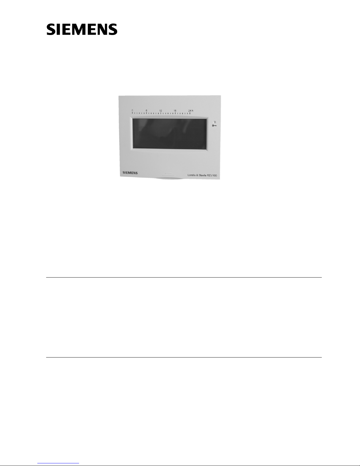
5RRP7HPSHUDWXUH
&RQWUROOHU
5(9
with touch screen
• 0DLQVLQGHSHQGHQWURRPWHPSHUDWXUHFRQWUROOHU
• 6HOIH[SODQDWRU\WRXFKVFUHHQ
• 6HOIOHDUQLQJWZRSRVLWLRQFRQWUROOHUZLWK3,'FRQWUROSDWHQWHG
• &KRLFHRIWZRGLIIHUHQWKRXURSHUDWLQJPRGHV
8VH
For the control of the room temperature in
• apartments, single-family or holiday houses
• offices, individual rooms and consulting rooms or commercially used spaces
For the control of the following pieces of equipment:
• Solenoid valves of instantaneous water heaters
• Solenoid valves of atmospheric gas burners
• Heating circulating pumps, zone valves (normally closed)
• Electric direct heating systems or fans of electric storage heaters
)XQFWLRQV
• PID control with self-learning or selectable switching cycle
• Two different 24-hour operating modes
• Remote control and override button
• Sensor balancing and reset function
• Locking of display to facilitate cleaning or to prevent tampering
• Frost protection function and minimum limitation of the setpoint
Page 2
2/8
Siemens Building Technologies Room temperature controller REV100 CE1N2211en
Landis & Staefa Division 16.05.2000
7\SHVXPPDU\
Room temperature controller with 24-hour time switch 5(9
When ordering, please give type reference according to "Type summary".
The unit is supplied complete with batteries.
0HFKDQLFDOGHVLJQ
Plastic casing with a large display which also serves as a touch screen. A hinged battery compartment cover facilitates the straightforward exchange of the two 1.5 V alkaline batteries type AA. The base can be removed and fitted to all commercially available
recessed conduit boxes or directly on the wall, to be wired before the control- ler is
fitted. The casing accommodates the electronics with a ',3switch and a relay with a
potential-free N.O. contact. The connection terminals are integrated in the base.
2211D11
5
1
2
6
3
4
7
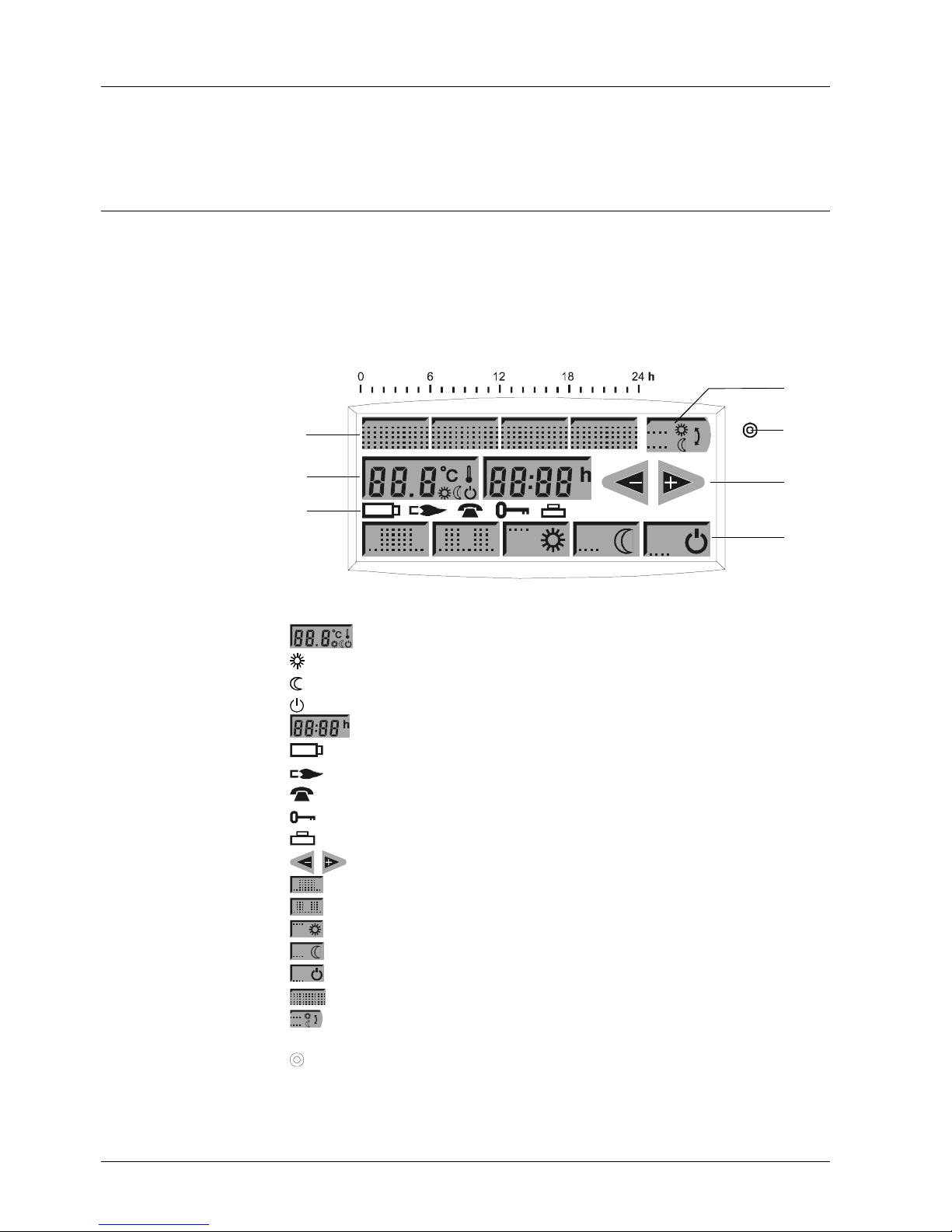
Temperature values and symbols
Normal temperature
Economy temperature
Standby with frost protection
Time of day or switching time
Change batteries
Bumer in operation
Remote control active
Locking of display active
Holiday program active
Increasing ,decreasing values
24-hour operation with one heating period
24-hour operation with two heating periods
Continuously normal temperature
Continuously economy temperature
Standby with frost protection
For the switching times 1 to 4
For switching manually from normal to economy temperature, or vice
versa
Opening for locking the display or for the reset
2UGHULQJDQG
GHOLYHU\
'LVSOD\DQGRSHUDWLQJ
HOHPHQWV
1 Display buttons
2 Symbols
3 Arrow buttons
4 Operating mode buttons
5 Switching time buttons
6 Level button
7 Locking ,reset
Page 3
3/8
Siemens Building Technologies Room temperature controller REV100 CE1N2211en
Landis & Staefa Division 16.05.2000
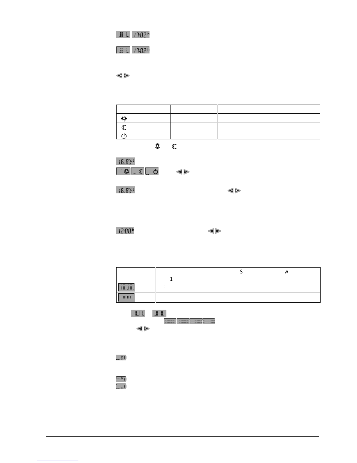
Not highlighted and no symbol: function cannot be selected.
Highlighted ,symbol visible: function can be selected but is not yet acti-
vated.
Highlighted ,symbol /angle bar visible at top left: function is activated.
When an adjustable display button is pressed, the displayed value will automatically be
stored 5 seconds later and the previous operating mode will be resumed or reactivated.
Pressing one ofthese buttons forless than one second produces a step ofone
minute (time settings) or of0.2 °C(temperature settings).
Pressing formore that one second means quick adjustment which can be cancelled
again by pressing the button repeatedly.
Standard value Setting range Setting range with setpoint limitation
20 °C 3…29 °C 16…29 °C
16 °C 3…29 °C 16…29 °C
5 °C 3...16 °C 3...16 °C
The setpoints of and are identical in both 24-hour operating modes.
Press the temperature button and then the required operating mode button.
. Press to adjust the setpoint temperature of each operating
mode.
Press the temperature button and then to readjust the displayed temperature in increments of 0.2 °C (max. ±4 °C) to the room temperature temporarily required. The warmer ,colder function can be applied to all three temperature setpoints,
but the values thus changed will be reset again when the next switching point is
reached.
Press the time button and then to set the correct time of day.
The two switching points forthe 24-hour operation with one heating period and the four
switching points forthe 24-hour operation with two heating periods can be entered
individually and independently.
Operating
mode
Switching
point
1
Switching
point2
Switching
point3
Switching
point4
06:00 09:00 17:00 22:00
07:00 23:00
Press or and select the individual switching points by pressing the respe ctiv e
switching time button . Then, change the displayed switching time by
pressing
.
• If two switching times coincide on the same switching time button, the display alter-
nates between the two switching points when pressing the button repeatedly
Manual changeover from the normal to the economy temperature, or vice versa.
The selection will automatically be reset when the next switching point is reached or
when changing the operating mode.
Manual changeover to the normal temperature is active
Manual changeover to the economy temperature is active
When absent fora longer period oftime, it is possible to switch manually to the economy temperature and to enter the period ofabsence.
'LVSOD\EXWWRQ
IXQFWLRQ
Automatic storage
Adjusting the values
6HWSRLQWV
$GMXVWLQJWKH
VHWSRLQWV
:DUPHU/ FROGHU
6HWWLQJWKHWLPHRIGD\
6ZLWFKLQJSRLQWV
Standard values
Changing the switching
points
2YHUULGHEXWWRQ
+ROLGD\SURJUDP
Page 4

4/8
Siemens Building Technologies Room temperature controller REV100 CE1N2211en
Landis & Staefa Division 16.05.2000
Select the economy temperature and press the time button, then enter the number of days you are absent
(max. 99 days). The display will show the number of days and the holiday symbol. Every midnight, the counter subtracts one day.
When the day counter reaches 00, the 24-hour operation with two heating phases will
automatically be resumed.
Press the day counter and set it to 00.
If the temperature displayed does not agree with the room temperature effectively
measured, the temperature sensor can be re-calibrated. For that purpose, set the DIP
switch for Sensor Alignment to ON and press the DIP switch button.
Press
to bring the flashing room temperature in line with the room temperature
currently measured. The increments for the readjustment are 0.2°C {max. ±2 °C).
When balancing of the sensor is completed, the DIP switch must be reset to OFF.
Before cleaning the display or to prevent tampering, the display buttons can be locked.
Press the button behind the little hole for a short moment (max. 1 second):
appears and all other displays disappear. The display buttons are now disabled while all
the other functions are fully maintained.
Press the button behind the little hole again (max. 1 second).
Keep the button behind the little hole depressed for at least 3 seconds. This resets the
individual settings and the time of day to their default values. During the reset time of 3
seconds, the display will be fully lit, allowing the proper functioning of the display to be
checked. After each reset, all personal settings such as time of day, weekday, switching points, temperature setpoints, sensor calibration, etc., must be re-entered.
About three months before the batteries are exhausted, the display shows the battery
symbol
. The other displays disappear, the display buttons are deactivated while
all the other functions are fully maintained. When changing the batteries, the current
data will remain stored for at least one minute.
Using a suitable remote operating unit, the REV100 can be switched to economy mode
. Changeover takes place by closing a SRWHQWLDOIUHHFRQWDFW connected to terminals
T1 and T2. In that case, symbol
appears on the display. When the contact opens,
the selected operating mode will be reactivated.
Operation according to controller setting Continuous economy temperature
T2
T1
2252Z05
T2
T1
2252Z06
Suitable remote operating units: telephone modem, manual switch, window switch,
occupancy detector, control centre, etc.
Enter
Cancel
6HQVRUFDOLEUDWLRQ
/RFNLQJWKHGLVSOD\
Switching on
Switching off
5HVHW
%DWWHU\FKDQJH
5HPRWHFRQWURO
Remote operating units
Page 5

5/8
Siemens Building Technologies Room temperature controller REV100 CE1N2211en
Landis & Staefa Division 16.05.2000
7HFKQLFDOGHVLJQ
123
PID 12
PID 6
2-Pt
2211D01
Self lear ning
16...29°C
3...29°C
Sensor Alignment
Disable
Enable
4
ON
1 342
2211Z32
Every Dip switch setting must be confirmed by pressing the Dip switch button.
Minimum limitation of the setpoint to 16 °C in buildings with several heating zones prevents heat from being transferred from one apartment to another. The function can be
selected with the ',3switch.
The REV100 is a two-position controller providing PID mode. The room temperature is
controlled by the cyclic switching of a regulating unit.
The controller comes with an activated self-learning operating mode, which means that
it automatically adapts to the type of controlled system (type of building construction,
type of radiator, size of room, etc.). On completion of a certain leaming phase, the controller automatically optimizes its parameters and then operates based on the mode
learned.
In exceptional cased where the self-learning mode does not represent the optimum
solution, it is possible to choose PID 12, PID 6 or the two-position mode.
PID 12 mode 12-minute switching cycle for normal to slow controlled systems (e.g.
massive houses, larger spaces, cast iron radiators, oil burner)
PID 6 mode 6-minute switching cycle for fast controlled systems (e.g. light building
structures, small rooms, plate radiators ,convectors, gas burner)
2-Pt mode Pure two-position controller with a switching differential of 0.5 °C
(± 0.25 °Cfor very difficult controlled systems with extreme outside
temperature variations
',36ZLWFK
6HWSRLQWOLPLWDWLRQ
&RQWURO
Self-learning mode
Exceptions
Page 6

6/8
Siemens Building Technologies Room temperature controller REV100 CE1N2211en
Landis & Staefa Division 16.05.2000
7HFKQLFDOGDWD
Operating voltage
Batteries (alkaline AA) 2 x 1.5 V
Life
Backup for battery change
DC 3 V
2 x 1.5 V
approx. 3 years
max. 1 min
Switching capacity of relays
Voltage
Current
AC 24…250 V
8 (3.5) A
Sensing element
Measurement range
Time constant
NTC 50 kΩ ±2 % at 25 °C
0…40 °C
max. 10 min
Setpoint setting range
Normal temperature
Economy temperature
Frost protection temperature
3…29 °C
3…29 °C
3...16 °C
Resolutions of settings and displays
Setpoints
Switching times
Measurement of actual value
Display of actual value
Display of time
0.2 °C
10 min
0.1 °C
0.2 °C
1 min
conformity
Electromagnetic compatibility
Low voltage directive
89/336/EEC
73/23/EEC
Electromagnetic compatibility
Immunity
Emissions
EN 50 082-2
EN 50 081-1
Safety class II to EN 60 730-1
Degree of protection IP30 to EN 60 529
Perm. ambient temperature
Operation
Storage and transport
3...35 °C
-25...+60 °C
Perm. ambient humidity G to DIN 40 040
Incl. packing 0.3 kg
Casing signal signal-white RAL9003
Base grey RAL7038
Housing 120 x 98 x 31 mm
1RWHV
• The room temperature controller should be fitted in the main living room
• The place of installation should be chosen so that the sensor can capture the room
temperature as accurately as possible without getting adversely affected by direct
solar radiation or other heating or refrigeration sources
• Mounting height is approximately 1.5 m above the ftoor
• The unit can be fitted to most commercially available recessed conduit boxes or
directly on the wall
General unit data
Norms and standards
Environmental
conditions
Weight
Colour
Seize
(QJLQHHULQJ
Page 7

7/8
Siemens Building Technologies Room temperature controller REV100 CE1N2211en
Landis & Staefa Division 16.05.2000
• When installing the controller, the base must first be fitted and wired. Then, the unit
can be engaged at the top, swung downward and snapped on
• For more detailed information, refer to the installation instructions supplied with the
unit
• For the electrical installation, the local safety regulations and standards must be
complied with
• The remote control contact T1/T2 must be wired separately, using a shielded cable
• The battery transit tab, which prevents inadvertent operation of the unit during trans-
port and storage, must be removed
• The control characteristic can be changed with the DIP switch located at the rear of
the unit
• If the reference room is equipped with thermostatic radiator valves, they must be set
to the fully open position
• If the room temperature displayed does not agree with the measured temperature,
the sensor should be re-calibrated (refer to section "Calibration of sensor").
&RQQHFWLRQGLDJUDP
L
L1
Y1
M1
N1
N
S1
T1 T2
2211A01
A
C
2
4
.
.
.
2
5
0
V
DC 3 V
L Live, AC 24 ... 250 V S1 Remote operating unit (potential-free)
L1 N.O. contact, AC 24 ... 250 V / 8 (3.5) A T1 Remote control signal
M1 Circulating pump T2 Remote control signal
N1 REV100 controller Y1 Regulating unit
0RXQWLQJDQG
LQVWDOODWLRQ
&RPPLVVLRQLQJ
Page 8

8/8
Siemens Building Technologies Room temperature controller REV100 CE1N2211en
Landis & Staefa Division 16.05.2000
$SSOLFDWLRQH[DPSOHV
T
T
)
)
1
0
<
2222S01
T
T
))
1
0
<
2222S02
T T
Instantaneous water heater Atmospheric gas burner
T
1
<
2222S03
0
Circulating pump with pre-control by manual mixing valve
F1 Thermal reset limit thermostat N1 REV11... room temperature controller
F2 Manual reset safe ty limi t ther mo s tat Y1 Manually operated three-port valve
M1 Circulating pump Y2 Solenoid valve
'LPHQVLRQV
120
98
31
2222M01
83,5
30
30
13
3030
10
2211M02
1999 Siemens Building Technologies Ltd.
Subject to change
www.landisstaefa.com/rev100
 Loading...