

Siemens Optiset E Standard,Advance Plus,Memory,Optiset E Advance Plus,Optiset E Memory Quick Reference Manual

Quick Reference Guide
Opti set E S t andard , Ad vance P lu s, and
Memory
for Hicom 150 E, OfficePoint,
OfficeCom, and OfficePro
Version 1.0
G281-0462-01

WARNING!
Hackers who unlawfully gain access to customer telecommunication systems
are criminals. Currently, we do not know of any telecommunications system
that is immune to this type of criminal activity. Siemens Business
Communication Systems, Inc. will not accept liability for any damages,
including long distance charges, which result fr om unauthorized use. Although
Siemens Business Communications has designed security features into its
products, it is your sole responsibility to use the security features and to
establish security practices within your company, including training, security
awareness, and call auditing.
Siemens Business Communications sales and service personnel, as well as
Siemens Business Communications business partners, are available to work
with you to help you prevent this type of unauthorized use of your
telecommunications system.
NOTE: The Siemens Optiset telephones for Hicom 150 E systems are hearingaid compatible and comply with the applicable FCC Rules, Part 68, and
Industry Canada CS-034 standard.
This equipment has been tested and found to comply with the limits for a Class
B digital device, pursua nt to Part 15 of the FC C Rules. These limits are designed
to provide reasonable protection against harmful interference in a residential
installation. This equipment generates, uses and can radiate radio frequency
energy and, if not installed and used in accordance with the instructions, may
cause harmful interference to radio communications. However, there is no
guarantee that interference will not occur in a particular installation. If this
equipment does cause harmful interference to radio or television reception,
which can be determined by turning the equipment off and on, the user is
encouraged to try to correct the interference by one or more of the following
measures:
- Reorient or relocate the receiving antenna.
- Increase the separation between the equipment and receiver.
- Connect the equipment into an outlet on a circuit different from that to
which the receiver is connected.
- Consult the dealer or an experienced radio/TV technician for help.
WARNING: Changes or modifications to the equipment that are not expressly
approved by the responsible party for compliance could void the user’s
authority to operate the equipment.
This equipment does not exceed Class B limits per radio noise emissions for
digital apparatus, set out in the Radio Interference Regulation of the Canadian
Department of Communications. Operation in a residential area may cause
unacceptable interference to radio and TV reception requiring the owner or
operator to take whatever steps are necessary to correct the interference.
Cet équipement ne dépasse pas les limites de Classe B d'émission de bruits
radioélectriques por les appareils numériques, telles que prescrites par le
Règlement sur le brouillage radioélectrique établi par le ministère des
Communications du Canada. L'exploitation faite en milieu résidentiel peut
entraîner le brouillage des réceptions radio et télé, ce qui obligerait le
propriétaire ou l'opérateur à prendre les dispositions nécessaires pour en
éliminer les causes.
September 1998
Form No. G281-0462-01 Part No. 06E0352ECNo. A93049
Job No. 4597

No part of this publication may be reproduced, stored in a retrieval system, or
transmitted, in any form or by any means, mechanical, electronic,
photocopying, recording, or otherwise, without prior written permission of
Siemens Business Communication Systems, Inc.
Request Siemens publications from your Siemens representative or the Siemens
branch serving you. Publications are not stocked at the address below.
Siemens Business Communication Systems, Inc.
4900 Old Ironsides Drive
P.O. Box 58075
Santa Clara, CA 95052-8075
(408) 492-2000
Siemens, Optiset, and PhoneMail are registered trademarks and Hicom is a
trademark of Siemens Aktiengesellschaft.
Copyright Siemens Business Communication Systems, Inc. 1998. All rights
reserved.


Contents
Welcome to Your Optiset E Standard, Advance Plus, and
Memory Telephones . . . . . . . . . . . . . . . . . . . . . . . . . . . . . . . . 1
Optiset E Standard Telephone . . . . . . . . . . . . . . . . . . . . . . . . 2
Optiset E Advance Plus Telephone . . . . . . . . . . . . . . . . . . . . 3
Optiset E Memory Telephone . . . . . . . . . . . . . . . . . . . . . . . . . 4
Bay Option Modules . . . . . . . . . . . . . . . . . . . . . . . . . . . . . . . . 6
Optiset E Local Power Supply . . . . . . . . . . . . . . . . . . . . . . . 10
Where to Go for Assistance . . . . . . . . . . . . . . . . . . . . . . . . . 11
Your Class of Service . . . . . . . . . . . . . . . . . . . . . . . . . . . . . . 11
Status Lights . . . . . . . . . . . . . . . . . . . . . . . . . . . . . . . . . . . . . 11
The OptiGuide Display . . . . . . . . . . . . . . . . . . . . . . . . . . . . . 12
Feature Keys and Access Codes . . . . . . . . . . . . . . . . . . . . . . 14
Setting up Your Telephone . . . . . . . . . . . . . . . . . . . . . . . . . . 14
Volume Keys . . . . . . . . . . . . . . . . . . . . . . . . . . . . . . . . . . . . 15
Sounds . . . . . . . . . . . . . . . . . . . . . . . . . . . . . . . . . . . . . . . . . . 16
Changing Your Audio Settings . . . . . . . . . . . . . . . . . . . . . . . 17
Callback Request . . . . . . . . . . . . . . . . . . . . . . . . . . . . . . . . . 18
Caller List . . . . . . . . . . . . . . . . . . . . . . . . . . . . . . . . . . . . . . . 19
Conference . . . . . . . . . . . . . . . . . . . . . . . . . . . . . . . . . . . . . . 20
Consultation . . . . . . . . . . . . . . . . . . . . . . . . . . . . . . . . . . . . . 23
Directed Call Pickup . . . . . . . . . . . . . . . . . . . . . . . . . . . . . . . 24
Forwarding . . . . . . . . . . . . . . . . . . . . . . . . . . . . . . . . . . . . . . 25
Hold . . . . . . . . . . . . . . . . . . . . . . . . . . . . . . . . . . . . . . . . . . . 26
Hold—Internal Consultation . . . . . . . . . . . . . . . . . . . . . . . . 27
Last Number Redial—Expanded . . . . . . . . . . . . . . . . . . . . . 28
Mailbox / Text Messages . . . . . . . . . . . . . . . . . . . . . . . . . . . 29
Park . . . . . . . . . . . . . . . . . . . . . . . . . . . . . . . . . . . . . . . . . . . . 31
Pickup . . . . . . . . . . . . . . . . . . . . . . . . . . . . . . . . . . . . . . . . . . 32
Repertory Dialing (Repdial) Keys . . . . . . . . . . . . . . . . . . . . 33
Saved Number Redial . . . . . . . . . . . . . . . . . . . . . . . . . . . . . . 34
Speakerphone . . . . . . . . . . . . . . . . . . . . . . . . . . . . . . . . . . . . 35
Station / Individual Speed Dialing . . . . . . . . . . . . . . . . . . . . 36
System Speed Dialing . . . . . . . . . . . . . . . . . . . . . . . . . . . . . . 37
Transfer . . . . . . . . . . . . . . . . . . . . . . . . . . . . . . . . . . . . . . . . . 38
Feature Access Codes . . . . . . . . . . . . . . . . . . . . . . . . . . . . . . 39
Index . . . . . . . . . . . . . . . . . . . . . . . . . . . . . . . . . . . . . . . . . . .I-1
Quick Reference Guide to Optiset Phones . . . . . . . . . . . . . A-1
v

vi Optiset E QRG
Welcome to Your Optiset E
Standard, Advance Plus, and
Memory Telephones
The Optiset E Standard, Advance Plus, and Memory digital
telephones work with your company’s Siemens Hicom 150
E Communications Server to give you advanced, easy-to-use
telephone features. (The communications server is your
company’s internal telecommunications system.)
2)
3)
4)
5)
1)
+
–
1 2 3
123
4 5 6
456
PQRST UV WXYZ
7 8 9
789
ABC DEF
MNOJKLGHI
0
0
8)
6)
7)
9)
10)
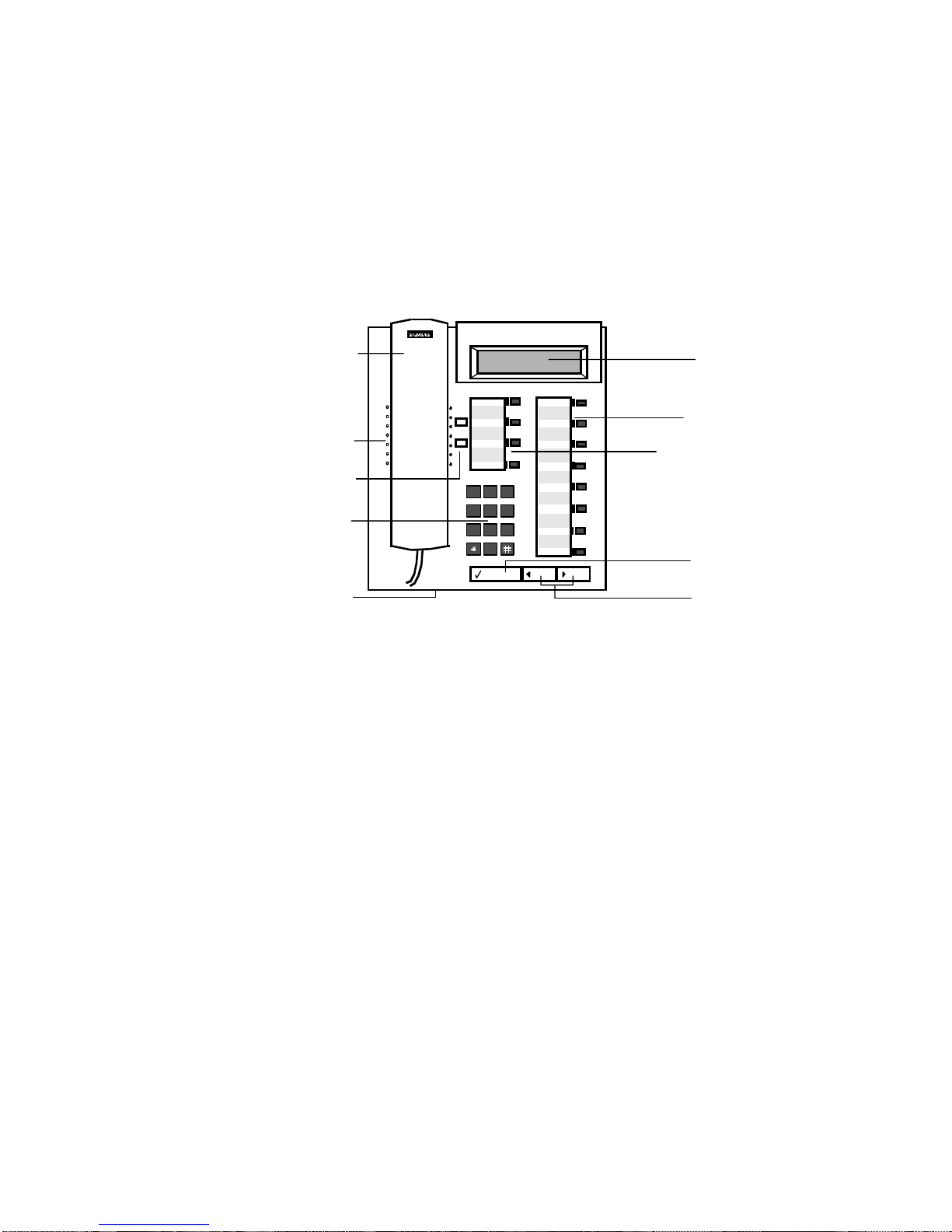
Figure 1. Optiset E Standard and Advance Plus Telephones
Handset
1)
Speaker (ringing tone/open listening)
2)
Volume keys for telephone settings
3)
Key pad
4)
Microphone for handsfree talking
5)
Display with 2 lines, 24 characters each
6)
Programmable feature keys
7)
Default feature keys
8)
Select OptiGuide key (confirms selection)
9)
Scrol l Forward an d Scroll Back Opti Guide
10)
keys (for browsing)
Welcome to Your Optiset E 1

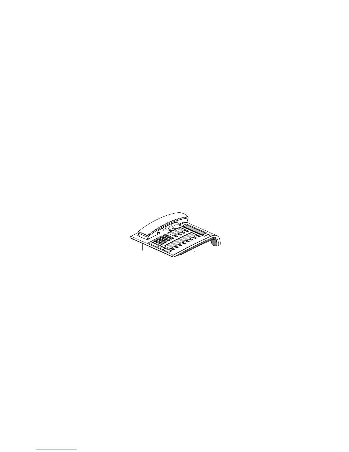
Optiset E Standard Telephone
The Optiset E Standard telephone has a microphone for a twoway speakerphone and does not support user-installable option
modules. The Standard and Advance Pl us telephones have four
default feature keys for the Program/Service, Redial, Mute, and
Speakerphone features. In addition, the eight programmable
feature keys can be used as either Repdial keys or userprefer red, comm only acce ssed fea ture keys . There is a two-l ine
tiltable display for viewing user prompts and the current
telephone settings.
microphone
Standard
Standard
microphone
Figure 2. Optiset E Standard Telephone
2 Optiset E QRG
Optiset E Advance Plus Telephone
The Optiset E Advance Plus telephone ha s two bays underneath
the base of the telephone for any of the following userinstallable option modules:
• Optiset E Analog Adapter
• Optiset E Data Adapter
• Optiset E Headset Adapter
• Optiset E Headset Plus Adapter
• Optiset E ISDN Adapter
• Optiset E Phone Adapter
• Optiset E Control Adapter
The Optiset E Advance Plus telephones also support up to four,
side-mounted Optiset E Key Module options, for a total of 64
additional feature keys a nd up to 29 line ext ensions. The Optiset
E Advance Plus telephone also has a microphone for a two-way
speakerphone.
microphone
Figure 3. Optiset E Advance Plus Telephone
Advance
Optiset E Advance Plus Telephone 3

Optiset E Memory Telephone
The Memory telephone has a microphone for a two-way
speaker telephone. T wo bays for opt ional adapters are under the
telephone. This telephone has an eight-l ine, tiltable display with
up to 24 characters per line.
The Memory telephone has four default feature keys for the
Program/Service, Redial, Mute, and Speakerphone features.
There are eight programmable feature keys that can be used as
either Repdial keys or user-preferred, commonly accessed
feature keys, and there are three OptiGuide keys for working
with the Siemens OptiGuide display.
The Memory telephone has an alphanumeric keyboar d used for
entering text in situations like programming names on stations,
sending custom text messages, and for entering names and
extensions in the Electronic Notebook included with the
telephone. The Electronic Notebook feature is used to store a
directory of data such as names, telephone numbers, and
telephone system features.
4 Optiset E QRG
3)
1)
2)
+
PQRS TUV
–
ABC DEF
MNOGHI
0
ABC DE F
123
MNOJKLGHI
456
PQRS T UV WXYZ
789
0
Program/Ser-
Redial
Mute
Speaker
6)
4)
8)
F1
F2
F3
F4
F5
7)
QW E R
ASZD
CTRL
9)
5)
F
XCV
ALTEDIT MENÜ E ND DIAL
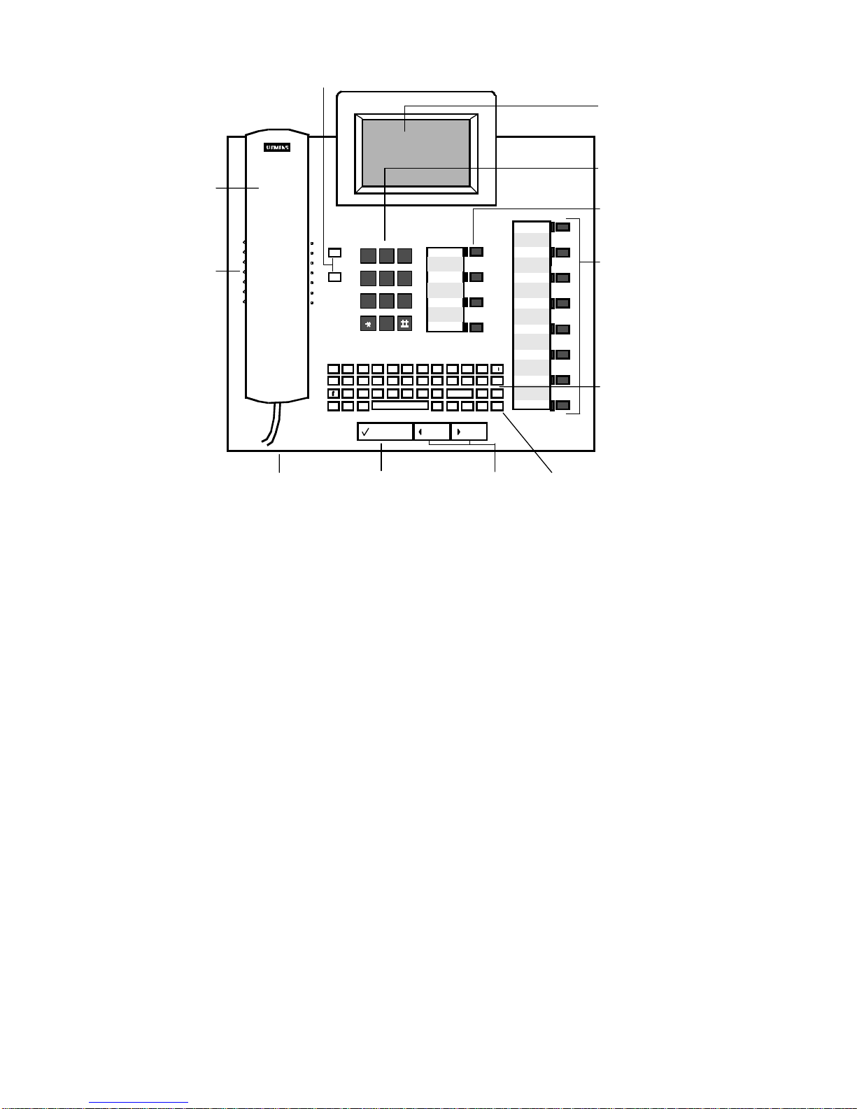
Figure 4. Optiset E Memory telephone
Features on the Memory Telephone
Handset
1)
Speaker under handset (ringing tone/open
2)
listening)
Volume keys for telephone settings
3)
Key pad
4)
Microphone for handsfree talking
5)
Tiltable display with 8 lines, 24 characters
6)
each
Programmable feature keys
7)
Default feature keys
8)
Select OptiGuide key (confirms selection)
9)
Scrol l Forward an d Scroll Back Opti Guide
10)
keys (for browsing)
Keyboard for message texts
11)
Cursor keys (for additional functions)
12)
TYUI PÜ
BNM
O
ÄÖLKJHG
↵←→
↑↓
F6
←
Delete
F7
F8
10) 12)
11)
Optiset E Memory Telephone 5

Bay Option Modules
The bay option modules sn ap into place in the bays underneath
the Advance Plus and Memory telephones. They are the same
size and shape, but labels clearly identify their type.
Figure 5. Bay Option Modules
Optiset E Analog Adapter
The Analog Adapter lets you attach a standard analog device,
such as a telephone, facsimile machine, modem, or answering
machine, to your telephone via an RJ11 connector on the back
of the adapter. The attached device is configured at your
communications server to be completely independent, with its
own telephone number. It can be attached to a standard
telephone cable up to 300 ft. long. This adapter requires the
Optiset E Local Power Supply for operation. (See “Optiset E
Local Power Supply” on page 10.)
Optiset E Data Adapter
The Data Adapter lets you connect your telephone to a
computer or terminal via a 25-pin connector for an EIA-232-E
cable. You can make asynchronous data calls by issuing AT
commands from your attached PC or terminal to your
telephone, much as you would to an attached modem. This
adapter supports baud rates of up to 38.4 kilobytes per second
(autobaud detection), simultaneous voice and data
communication, hardware flow control (RTS/CTS), and full
duplex operation. It also supports the Siemens Application
Programming Interface (API), data loopback for customer
service tests, and V.120 and DMI mode 2-Bit Rate Adaptation.
Optiset E Headset Adapter
The Headset Adapter lets you plug one or two electret
microphone-type headsets into your telephone. You can then
make and answer calls using a headset instead of the handset or
the telephone’s built-in microphone and speaker. This type of
6 Optiset E QRG

headset does not require an amplifier. Connection is made
through two RJ8 connectors. Only the Optiset E Advance Plus
and Memory telephones support this option. When a headset is
plugged into the adapter, the speakerphone does not function.
Optiset E Headset Plus Adapter
The Optiset E Headset Plus Adapter lets you plug one or two
carbon microphone-type headsets and a recorder into your
telephone. You can then make and answer calls handsfree by
using a headset instead of the handset or the telephone’s builtin microphone and speaker.
This type of headset requires an amplifier. You can also record
your conversations. The headsets attach to two RJ8 connectors.
The recor der attaches to an RJ11 connector. Only the Optiset E
Advance Plus and Memory telephones support this option.
When a headset is plugged into the adapter, the speakerphone
does not function. The recorder works without a headset being
plugged in.
Optiset E ISDN Adapter
The ISDN Adapter lets you connect ISDN S0 bus devices such
as telephones, PC cards, LAN Bridges, G4 fax machines, and
video equipment to your telephone via an RJ45 connector. It
supports up to 64 kilobytes per second simultaneously on each
bearer channel. It will only work properly in a primary
telephone, not in a t elephone attached to anot her telephone with
the Phone Adapter. You can only connect two ISDN devices to
the adapter.
Optiset E Phone Adapter
The Phone Adapter lets you attach another Optiset E telephone
to your Basic telephone. It provides an RJ11 connector; you can
attach the second t elephone via a standard telephone c able up to
300 feet long. You can then place the second telephone in an
area not wired for a telephone. The attached telephone is
configured at your communications server to be a completely
independent telephone with its own telephone number.
Optiset E Control Adapter
The Optiset E Control Adapter (TA Control) lets you connect a
PC and a headset to an Optiset E telephone (except Optiset E
Entry and Optiset E Basic). The Optiset E Control Adapter
operates in both API1 mode and API2 mode.
Bay Option Modules 7
2
1
3
4
5
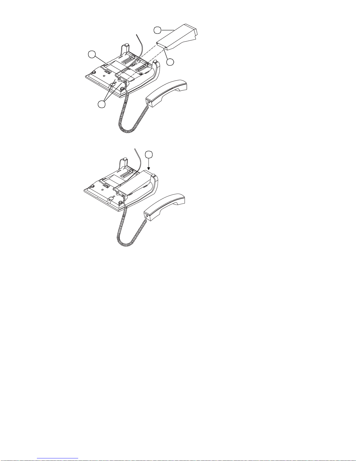
Figure 6. Installation of Bay Option Modules
To install a bay option module
1. Disconnect the telephone line from the wall j ack or telephone
and place the telephone ➀ on a soft surface with the keypad
facing down.
2. Hold t he adapt er ➁ with t he plug connec tor strip facing dow n
and mount it in one of the two mounting locations on the
bottom of the telephone, sliding the two tabs ➂ into the two
slots ➃.
3. Gently press down on the adapter until the plug connector
strip is inserted all the way into the socket connector strip ➄.
For the
Analog Adapter
RJ11 port on the back of the Analog Adapter (connecting tip/
ring to pins 3 and 4). Reconnect the telephone line to the
telephone. Note, t he analog ada pter requires the Optiset E Local
Power Supply for operation.
, connect an analog device to the 6-pin
8 Optiset E QRG

For the
Da ta Ada pter
, connect the data terminal equipment to
the 25-pin (EIA-232) connector on the back of the Data
Adapter. Reconnect the telephone line to the telephone.
For the
Headset Adapter,
connect the headset to the headset
(RJ8) connector on the adapter. Reconnect the telephone line to
the telephone.
For the
Headset Plus Adapter
, connect the headset to the
hea dset (RJ 8) connecto r on the ad apter. C onnect the recorder to
the recorder (RJ11) connector. Reconnect the telephone line to
the telephone.
For the
ISDN Adapter
, connect the ISDN termi nal to the RJ45
adapter. Reconnect the telephone line to the telephone.
For the
Phone Adapter
, connect the secondary Optiset E
telephone into the RJ11 connector on the adapter. Re connect the
telephone line to the telephone.
For the
Control Adapter
, connect the headset to the headset
(RJ8) connector on the adapter. Connect the PC from the serial
port on the PC to the (RS232) connector on the adapter.
Reconnect the telephone line to the telephone.
Optiset E Key Module
The side-mounted Optiset E Key Module adds 16 keys for
features and line appearances. Up to four Optiset E Key
Modules can be linked together on one telephone for a total of
64 additional feature keys and up to 29 line appearances. Only
the Optiset E Advance Plus and Memory telephones support
this option. Wall mount kits do not support telephones with an
Optiset E Key Module attached.
Figure 7. Optiset E Key Module
Bay Option Modules 9

Optiset E Local Power Supply
u
The Local Power Supply is required for the Analog Adapter. It
may also be required in other situations, depending on the
Optiset E telephone’s configuration, the type of telephone cable
used, the length of the telephone cable from the
communications server, and the type of communications server
used. Only one Optiset E Local Power Supply can be used at a
time on an Optiset E telephone. However, one Local Power
Supply can be used on a primary telephone and a second Local
Power Supply can be use d on a secondary telephone attached to
the primary telephone through a Phone Adapter.
Installation of Local Power Supply
To install a local power supply:
1. Disconnect the telephone line from the wall jack and the
telephone. New telephones should have a line cord attached
to the telephone, but may not be plugged into the wall jack.
Plug the line cord (PN 51A4871) ➀ that comes with the
power supply int o the jack on t he telephone and into the jack
on the power supply labeled .
Digital
2. Plug one end ➁ of the line cord that you disconnected from
the telephone into the jack on the power supply labeled .
3. Plug the other end ➂ of this line cord into the wall jack. Note,
you could also plug it into an Optiset E Phone Adapter
installed in another properly installed telephone.
4. Plug the power supply ➃ into a properly grounded 120 Vac
electrical outlet.
Digital
1
Advance Pl
4
2
3
10 Optiset E QRG
 Loading...