


 Loading...
COROS
Operator Panel
OP25, OP35, OP45
Equipment Manual
6AV3991±1AD02±0AB0
Preface, Table of Contents
Introduction
Functions od the Operator Panel
Commissioning and Operation
Device Description,
Installation and Maintenance
Appendices
Glossary, Index
Release 04/96

Safety Guidelines
!
!
Qualified Personnel
This manual contains notices which you should observe to ensure your own personal safety, as well as to protect the product and connected equipment. These notices are highlighted in the manual by a warning triangle and are marked as follows according to the level of danger:
Danger
indicates that death, severe personal injury or substantial property damage can result if proper precautions are not taken.
Caution
indicates that minor personal injury or property damage can result if proper precautions are not taken.
Note
draws your attention to particularly important information on the product, handling the product, or to a particular part of the documentation.
Equipment may be commissioned and operated only by qualified personnel. Qualified personnel within the meaning of the safety notices in this manual are persons who are authorized to commission, ground and identify equipment, systems and circuits in accordance with safety engineering standards.
Correct Usage
!
Trademarks
Impressum
Note the following:
Warning
The equipment may be used only for the applications stipulated in the catalog and in the technical description and only in conjunction with other equipment and components recommended or approved by Siemens.
Faultless and safe operation of the product presupposes proper transportation, proper storage, erection and installation as well as careful operation and maintenance.
Startup must not take place until it is established that the machine, which is to accommodate this component, is in conformity with the guideline 89/392/EEC.
SIMATIC and SINEC are registered trademarks of SIEMENS AG. Some of the other designations used in these documents are also registered trademarks; the owner's rights may be violated if they are used be third parties for their own purposes.
Published by AUT 91
Copyright Siemens AG 1996 All rights reserved
The reproduction, transmission or use of this document or its contents is not permitted without express written authority.
Offenders will be liable for damages. All rights, including rights created by patent grant or registration of a utility model or design, are reserved.
Siemens AG
Automation Group
Industrial Automation Systems
P.O. Box 4848, D-90327 Nürnberg
i l i r i ili
We have checked the contents of this manual for agreement with the hardware and software described. Since deviations cannot be precluded entirely, we cannot guarantee full agreement. However, the data in this manual are reviewed regularly and any necessary corrections included in subsequent editions. Suggestions for improvement are welcomed.
Technical data subject to change.Siemens AG 1995, 1996
Siemens Aktiengesellschaft |
Order No. 6AV3991±1AD02±0AB0 |

Preface
Purpose |
This equipment manual contains precise information about the functionality |
|||
|
and technical design of operator panels OP25, OP35, and OP45. |
|
||
Audience |
The present equipment manual is written for operators, fitters, configurers, and |
|||
|
system support engineers. |
|
|
|
|
The operator of an operator panel will find all the information he requires for |
|||
|
handling the device in Part II. |
|
|
|
|
For the fitter, Part IV contains all the information he requires to install and |
|||
|
commission the operator panel. |
|
|
|
Applicability |
The different versions of the equipment manual refer to the following OP firm- |
|||
|
ware and ProTool versions: |
|
|
|
|
|
|
|
|
|
Release |
Remarks |
OP Firmware |
ProTool |
|
|
|
|
Version |
|
|
|
|
|
|
04/95 |
Initial release of Equipment |
OP25: from V. 1.31 |
Up to V. 1.31 |
|
|
Manual |
OP35: from V. 1.31 |
Up to V. 1.31 |
|
|
Summary of OP25, OP35 Equip- |
OP45: from V. 1.31 |
Up to V. 1.31 |
|
|
|
|
|
|
|
ment Manual, and OP45 added |
|
|
|
|
|
|
|
|
10/95 |
Extensions for Release 2 |
OP25: from V. 1.31 |
Up to V 2.0 |
|
|
|
OP35: from V. 1.31 |
Up to V 2.0 |
|
|
|
OP45: from V. 1.31 |
Up to V. 2.0 |
|
|
|
|
|
|
04/96 |
SINEC L2-DP for OP45 and MPI |
OP25: from V. 2.0 |
Up to V 2.0 |
|
|
for SIMATIC S7 added |
OP35: from V. 2.0 |
Up to V 2.0 |
|
|
|
OP45: from V. 1.40 |
V. 2.01 |
|
1) As well as an upgrade floppy disk |
|
|
|
Further support |
Should you have any queries regarding technical matters, please get into touch |
|||
|
with your point of contact at the Siemens agency or branch responsible. You |
|||
|
will find the addresses in Appendix F of this manual, in catalogs, and in Com- |
|||
|
puserve (go autforum) ..., for instance. In addition, you can call our hotline by |
|||
|
dialing +49(911) 895-7000 (fax 7001). |
|
|
|
Conventions |
The following conventions are used in this manual: |
|
||
|
Trans Mode Text on the display of the OP appears in the manual in |
|||
|
|
Courier |
|
|
|
Login: |
Field name on screens |
|
|
|
( section 7.2) Cross-reference, reference to additional information |
|||
Equipment Manuel OP25, OP35, OP45 |
|
|
i |
|
Release 04/96 |
|
|
|
|
Preface
How the manual is The OP25/35/45 Equipment Manual is organized as follows:
organized
Chapters 1 to 2 provide an overview of the operator panels and their functions in tabular form.
Chapters 3 to 9 describe in step-by-step instructions how to operate operator panels ± for example, how to
±create new screens (in addition to the standard screens)
±output messages or alarms
±enter recipe data records
±print messages or screens.
Chapters 10 to 13 contain information on
±how you commission operator panels
±which system settings you can perform, and
±how you can back up and restore data.
|
Chapters 14 to 18 contain detailed information about the different devices, |
|||
|
|
as well as their mechanical and electrical installation and |
||
|
|
maintenance. |
|
|
|
In the appendices you will such items as technical data, interface assign- |
|||
|
|
ments, test functions, and system messages. |
||
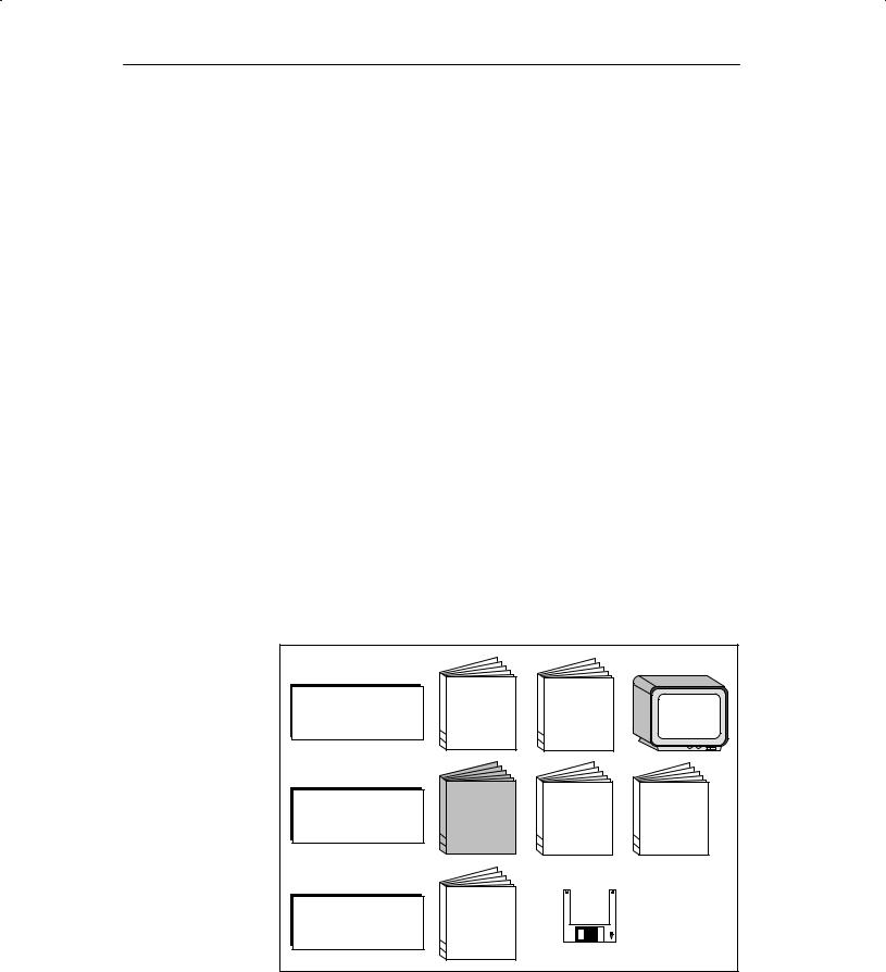
Related |
The illustration shown below provides an overview of how the complete range |
|||
documents |
of documents covering manuals and online help is organized. The present |
|||
|
manual is shaded. |
|
|
|
|
PC |
|
|
|
|
Configuration |
|
L ! |
|
|
" |
" |
||
|
|
|
||
|
OP |
|
|
|
|
Installation |
|
|
|
|
Operation |
E " ! |
E " ! |
E " ! |
|
|
" |
" |
" |
|
PLC |
|
|
|
|
Connection |
C " # |
|
|
|
! |
|
|
|
|
|
" |
|
|
|
|
|
! LC |
|
ii |
Equipment Manuel OP25, OP35, OP45 |
Release 04/96 |

Table of Contents
Part I: Introduction
1 |
Product Description . . . . . . . . . . . . . . . . . . . . . . . . . . . . . . . . . . . . . . . . . . . . . . . . . . . . . |
1-1 |
|
|
1.1 |
The Operator Panel at a Glance . . . . . . . . . . . . . . . . . . . . . . . . . . . . . . . . . . . |
1-3 |
|
1.2 |
Process Visualization and Manipulation . . . . . . . . . . . . . . . . . . . . . . . . . . . . . |
1-5 |
2 |
Functionality . . . . . . . . . . . . . . . . . . . . . . . . . . . . . . . . . . . . . . . . . . . . . . . . . . . . . . . . . . . . |
2-1 |
|
Part II: Functions of the Operator Panel
3 |
Using the OP . . . . . . . . . . . . . . . . . . . . . . . . . . . . . . . . . . . . . . . . . . . . . . . . . . . . . . . . . . . . |
3-1 |
|
|
3.1 |
Keyboard . . . . . . . . . . . . . . . . . . . . . . . . . . . . . . . . . . . . . . . . . . . . . . . . . . . . . . . |
3-2 |
|
3.2 |
Input/Output Fields . . . . . . . . . . . . . . . . . . . . . . . . . . . . . . . . . . . . . . . . . . . . . . . |
3-5 |
|
3.2.1 |
Numeric Fields . . . . . . . . . . . . . . . . . . . . . . . . . . . . . . . . . . . . . . . . . . . . . . . . . . |
3-6 |
|
3.2.2 |
String Fields . . . . . . . . . . . . . . . . . . . . . . . . . . . . . . . . . . . . . . . . . . . . . . . . . . . . . |
3-7 |
|
3.2.3 |
Symbolic Fields . . . . . . . . . . . . . . . . . . . . . . . . . . . . . . . . . . . . . . . . . . . . . . . . . . |
3-9 |
|
3.3 |
Using the Windows of OP25/OP35 . . . . . . . . . . . . . . . . . . . . . . . . . . . . . . . . . |
3-10 |
4 |
Screens |
. . . . . . . . . . . . . . . . . . . . . . . . . . . . . . . . . . . . . . . . . . . . . . . . . . . . . . . . . . . . . . . . . |
4-1 |
|
4.1 |
The Operator Panel in Action . . . . . . . . . . . . . . . . . . . . . . . . . . . . . . . . . . . . . . |
4-2 |
|
4.2 |
Screen Elements . . . . . . . . . . . . . . . . . . . . . . . . . . . . . . . . . . . . . . . . . . . . . . . . . |
4-4 |
|
4.3 |
Selecting a Screen . . . . . . . . . . . . . . . . . . . . . . . . . . . . . . . . . . . . . . . . . . . . . . . |
4-5 |
|
4.4 |
Standard Screens . . . . . . . . . . . . . . . . . . . . . . . . . . . . . . . . . . . . . . . . . . . . . . . . |
4-6 |
5 |
Messages . . . . . . . . . . . . . . . . . . . . . . . . . . . . . . . . . . . . . . . . . . . . . . . . . . . . . . . . . . . . . . . |
5-1 |
|
|
5.1 |
Event and Alarm Messages . . . . . . . . . . . . . . . . . . . . . . . . . . . . . . . . . . . . . . . |
5-2 |
|
5.1.1 |
General Features . . . . . . . . . . . . . . . . . . . . . . . . . . . . . . . . . . . . . . . . . . . . . . . . |
5-3 |
|
5.1.2 |
Current Messages . . . . . . . . . . . . . . . . . . . . . . . . . . . . . . . . . . . . . . . . . . . . . . . |
5-5 |
|
5.1.3 |
Stored Messages . . . . . . . . . . . . . . . . . . . . . . . . . . . . . . . . . . . . . . . . . . . . . . . . |
5-8 |
|
5.1.4 |
Standard Screen: Message Processing . . . . . . . . . . . . . . . . . . . . . . . . . . . . . |
5-10 |
|
5.2 |
System Messages . . . . . . . . . . . . . . . . . . . . . . . . . . . . . . . . . . . . . . . . . . . . . . . |
5-11 |
6 |
Recipes . |
. . . . . . . . . . . . . . . . . . . . . . . . . . . . . . . . . . . . . . . . . . . . . . . . . . . . . . . . . . . . . . . . |
6-1 |
|
6.1 |
Processing and Transferring the Data Records . . . . . . . . . . . . . . . . . . . . . . . |
6-4 |
6.1.1Standard Screens: Data Record Processing and
|
Data Record Transferring . . . . . . . . . . . . . . . . . . . . . . . . . . . . . . . . . . . . . . . . . |
6-5 |
6.1.2 |
Setting Up and Editing Data Records . . . . . . . . . . . . . . . . . . . . . . . . . . . . . . . |
6-8 |
Equipment Manuel OP25, OP35, OP45 |
iii |
|
Release 04/96 |
|
|

Table of Contents
|
6.2 |
Parameter Records . . . . . . . . . . . . . . . . . . . . . . . . . . . . . . . . . . . . . . . . . . . . . . |
6-11 |
7 |
Print Functions . . . . . . . . . . . . . . . . . . . . . . . . . . . . . . . . . . . . . . . . . . . . . . . . . . . . . . . . . . |
7-1 |
|
|
7.1 |
Hardcopy . . . . . . . . . . . . . . . . . . . . . . . . . . . . . . . . . . . . . . . . . . . . . . . . . . . . . . . |
7-2 |
|
7.2 |
Message Logging . . . . . . . . . . . . . . . . . . . . . . . . . . . . . . . . . . . . . . . . . . . . . . . . |
7-2 |
|
7.3 |
Forced Logging . . . . . . . . . . . . . . . . . . . . . . . . . . . . . . . . . . . . . . . . . . . . . . . . . . |
7-2 |
|
7.4 |
Printing Screen List (OP25, OP35 Only) . . . . . . . . . . . . . . . . . . . . . . . . . . . . . |
7-3 |
8 |
Password Protection . . . . . . . . . . . . . . . . . . . . . . . . . . . . . . . . . . . . . . . . . . . . . . . . . . . . |
8-1 |
|
|
8.1 |
Logging In on the OP . . . . . . . . . . . . . . . . . . . . . . . . . . . . . . . . . . . . . . . . . . . . . |
8-2 |
|
8.2 |
Logging Out on the OP (Logout) . . . . . . . . . . . . . . . . . . . . . . . . . . . . . . . . . . . |
8-3 |
|
8.3 |
Password Management . . . . . . . . . . . . . . . . . . . . . . . . . . . . . . . . . . . . . . . . . . . |
8-4 |
9 |
Status/Force Variable with the OP . . . . . . . . . . . . . . . . . . . . . . . . . . . . . . . . . . . . . . . . |
9-1 |
|
|
9.1 |
Status Variable . . . . . . . . . . . . . . . . . . . . . . . . . . . . . . . . . . . . . . . . . . . . . . . . . . |
9-2 |
|
9.2 |
Force Variable . . . . . . . . . . . . . . . . . . . . . . . . . . . . . . . . . . . . . . . . . . . . . . . . . . . |
9-5 |
Part III: Commissioning and Operation
10 Commissioning . . . . . . . . . . . . . . . . . . . . . . . . . . . . . . . . . . . . . . . . . . . . . . . . . . . . . . . . . |
10-1 |
10.1 Initial Commissioning of the OP25/OP35 . . . . . . . . . . . . . . . . . . . . . . . . . . . . 10-2 10.2 Initial Commissioning of the OP45 . . . . . . . . . . . . . . . . . . . . . . . . . . . . . . . . . . 10-3 10.3 Recommissioning . . . . . . . . . . . . . . . . . . . . . . . . . . . . . . . . . . . . . . . . . . . . . . . . 10-4 10.4 MPI Transfer (OP25/35 only) . . . . . . . . . . . . . . . . . . . . . . . . . . . . . . . . . . . . . . 10-5 10.5 Startup Sequence . . . . . . . . . . . . . . . . . . . . . . . . . . . . . . . . . . . . . . . . . . . . . . . . 10-6 10.6 Error Diagnosis . . . . . . . . . . . . . . . . . . . . . . . . . . . . . . . . . . . . . . . . . . . . . . . . . . 10-7 10.7 Notes on Data Security . . . . . . . . . . . . . . . . . . . . . . . . . . . . . . . . . . . . . . . . . . . 10-8
11 System Settings . . . . . . . . . . . . . . . . . . . . . . . . . . . . . . . . . . . . . . . . . . . . . . . . . . . . . . . . . 11-1
11.1 Standard Screen: System Settings . . . . . . . . . . . . . . . . . . . . . . . . . . . . . . . . . 11-2 11.2 Standard Screen: Printer Settings . . . . . . . . . . . . . . . . . . . . . . . . . . . . . . . . . . 11-3 11.3 Blanking Circuit (OP25/35 Only) . . . . . . . . . . . . . . . . . . . . . . . . . . . . . . . . . . . 11-5 11.4 Contrast and Brightness Adjustment on the OP25/35 . . . . . . . . . . . . . . . . . 11-6 11.5 System-Related Key Assignments (OP45 Only) . . . . . . . . . . . . . . . . . . . . . . 11-7 11.6 User-Specific Key Assignment (OP45 Only) . . . . . . . . . . . . . . . . . . . . . . . . . 11-8
12 Operating Modes . . . . . . . . . . . . . . . . . . . . . . . . . . . . . . . . . . . . . . . . . . . . . . . . . . . . . . . . |
12-1 |
12.1 Normal Operation, Loop-Through Operation and Transfer Mode . . . . . . . 12-2 12.2 Setting/Changing the Operation Mode . . . . . . . . . . . . . . . . . . . . . . . . . . . . . . 12-3 12.3 DOS Operation with the OP45 . . . . . . . . . . . . . . . . . . . . . . . . . . . . . . . . . . . . . 12-4
iv |
Equipment Manuel OP25, OP35, OP45 |
Release 04/96 |

Table of Contents
13 Storing and Loading Data . . . . . . . . . . . . . . . . . . . . . . . . . . . . . . . . . . . . . . . . . . . . . . . . |
13-1 |
13.1 Storage Principle and Storage Media (Data Media) . . . . . . . . . . . . . . . . . . . 13-2 13.2 Backup and Restore with the OP25/35 . . . . . . . . . . . . . . . . . . . . . . . . . . . . . . 13-4
Part IV: Device Description, Installation, and Maintenance
14 |
Device Description . . . . . . . . . . . . . . . . . . . . . . . . . . . . . . . . . . . . . . . . . . . . . . . . . . . . . . |
14-1 |
|
|
14.1 |
Device Description: OP25 . . . . . . . . . . . . . . . . . . . . . . . . . . . . . . . . . . . . . . . . |
14-2 |
|
14.1.1 |
Operating and Indicating Elements of the OP25 . . . . . . . . . . . . . . . . . . . . . . |
14-2 |
|
14.1.2 |
Connections of the OP25 . . . . . . . . . . . . . . . . . . . . . . . . . . . . . . . . . . . . . . . . . |
14-3 |
|
14.1.3 |
Dimensions of the OP25 . . . . . . . . . . . . . . . . . . . . . . . . . . . . . . . . . . . . . . . . . . |
14-4 |
|
14.2 |
Device Description: OP35 . . . . . . . . . . . . . . . . . . . . . . . . . . . . . . . . . . . . . . . . |
14-5 |
|
14.2.1 |
Operating and Indicating Elements of the OP35 . . . . . . . . . . . . . . . . . . . . . . |
14-5 |
|
14.2.2 |
Connections/Interfaces of the OP35 . . . . . . . . . . . . . . . . . . . . . . . . . . . . . . . . |
14-6 |
|
14.2.3 |
Dimensions of the OP35 . . . . . . . . . . . . . . . . . . . . . . . . . . . . . . . . . . . . . . . . . . |
14-7 |
|
14.3 |
Device Description: OP45 . . . . . . . . . . . . . . . . . . . . . . . . . . . . . . . . . . . . . . . . |
14-8 |
|
14.3.1 |
Operating and Indicating Elements of the OP45 . . . . . . . . . . . . . . . . . . . . . . |
14-8 |
|
14.3.2 |
Connections of the OP45 . . . . . . . . . . . . . . . . . . . . . . . . . . . . . . . . . . . . . . . . . |
14-10 |
|
14.3.3 |
Dimensions of the OP45 . . . . . . . . . . . . . . . . . . . . . . . . . . . . . . . . . . . . . . . . . . |
14-12 |
|
14.4 |
Options . . . . . . . . . . . . . . . . . . . . . . . . . . . . . . . . . . . . . . . . . . . . . . . . . . . . . . . . . |
14-13 |
|
14.4.1 |
Direct Key Module for the OP25 . . . . . . . . . . . . . . . . . . . . . . . . . . . . . . . . . . . . |
14-14 |
|
14.4.2 |
Direct Key Module for the OP35 . . . . . . . . . . . . . . . . . . . . . . . . . . . . . . . . . . . . |
14-16 |
15 |
Labelling the Function Keys . . . . . . . . . . . . . . . . . . . . . . . . . . . . . . . . . . . . . . . . . . . . . . |
15-1 |
|
|
15.1 |
Labelling the Keys for OP25 . . . . . . . . . . . . . . . . . . . . . . . . . . . . . . . . . . . . . . . |
15-2 |
|
15.2 |
Labelling the Keys for OP35 . . . . . . . . . . . . . . . . . . . . . . . . . . . . . . . . . . . . . . . |
15-3 |
|
15.3 |
Labelling the Keys for OP45 . . . . . . . . . . . . . . . . . . . . . . . . . . . . . . . . . . . . . . . |
15-6 |
16 |
Mechanical Installation . . . . . . . . . . . . . . . . . . . . . . . . . . . . . . . . . . . . . . . . . . . . . . . . . . |
16-1 |
|
|
16.1 |
Installing the OP25 . . . . . . . . . . . . . . . . . . . . . . . . . . . . . . . . . . . . . . . . . . . . . . . |
16-2 |
|
16.2 |
Installing the OP35 . . . . . . . . . . . . . . . . . . . . . . . . . . . . . . . . . . . . . . . . . . . . . . . |
16-5 |
|
16.2.1 |
Installation in 19º Cabinets/Racks . . . . . . . . . . . . . . . . . . . . . . . . . . . . . . . . . . |
16-5 |
|
16.2.2 |
Installation in Switching Cabinets/Consoles . . . . . . . . . . . . . . . . . . . . . . . . . . |
16-6 |
|
16.3 |
Installing the OP45 . . . . . . . . . . . . . . . . . . . . . . . . . . . . . . . . . . . . . . . . . . . . . . . |
16-8 |
|
16.3.1 |
Installation in 19º Cabinets/Racks . . . . . . . . . . . . . . . . . . . . . . . . . . . . . . . . . . |
16-9 |
|
16.3.2 |
Installation in Switching Cabinets/Consoles . . . . . . . . . . . . . . . . . . . . . . . . . . |
16-11 |
17 |
Electrical Installation . . . . . . . . . . . . . . . . . . . . . . . . . . . . . . . . . . . . . . . . . . . . . . . . . . . . |
17-1 |
|
|
17.1 |
Electrical Installation of the OP25/OP35 . . . . . . . . . . . . . . . . . . . . . . . . . . . . . |
17-2 |
|
17.1.1 |
Connecting the Voltage Supply and Relay Contacts . . . . . . . . . . . . . . . . . . |
17-3 |
|
17.1.2 |
Connecting the Configuration Computer . . . . . . . . . . . . . . . . . . . . . . . . . . . . |
17-4 |
|
17.1.3 |
Link to the Controller . . . . . . . . . . . . . . . . . . . . . . . . . . . . . . . . . . . . . . . . . . . . . |
17-5 |
|
17.1.4 |
Connecting the Printer . . . . . . . . . . . . . . . . . . . . . . . . . . . . . . . . . . . . . . . . . . . . |
17-6 |
|
17.1.5 |
Loop-Through Operation . . . . . . . . . . . . . . . . . . . . . . . . . . . . . . . . . . . . . . . . . . |
17-7 |
|
17.2 |
Electrical Installation of the OP45 . . . . . . . . . . . . . . . . . . . . . . . . . . . . . . . . . . |
17-8 |
|
17.2.1 |
Connection to the Power Supply . . . . . . . . . . . . . . . . . . . . . . . . . . . . . . . . . . . |
17-9 |
Equipment Manuel OP25, OP35, OP45 |
v |
||
Release 04/96 |
|
||

Table of Contents
|
17.2.2 |
Connecting the Configuration Computer . . . . . . . . . . . . . . . . . . . . . . . . . . . . |
17-10 |
|
17.2.3 |
Link to the Controller . . . . . . . . . . . . . . . . . . . . . . . . . . . . . . . . . . . . . . . . . . . . . |
17-10 |
|
17.2.4 |
Connecting the Printer . . . . . . . . . . . . . . . . . . . . . . . . . . . . . . . . . . . . . . . . . . . . |
17-11 |
|
17.2.5 |
Connecting an MF2 Keyboard . . . . . . . . . . . . . . . . . . . . . . . . . . . . . . . . . . . . . |
17-12 |
18 |
Maintenance . . . . . . . . . . . . . . . . . . . . . . . . . . . . . . . . . . . . . . . . . . . . . . . . . . . . . . . . . . . . |
18-1 |
|
|
18.1 |
Backup Battery . . . . . . . . . . . . . . . . . . . . . . . . . . . . . . . . . . . . . . . . . . . . . . . . . . |
18-2 |
|
18.2 |
Display . . . . . . . . . . . . . . . . . . . . . . . . . . . . . . . . . . . . . . . . . . . . . . . . . . . . . . . . . |
18-5 |
|
18.2.1 |
Replacing the Display for the OP25 . . . . . . . . . . . . . . . . . . . . . . . . . . . . . . . . . |
18-6 |
|
18.2.2 |
Replacing the Display for the OP35 . . . . . . . . . . . . . . . . . . . . . . . . . . . . . . . . . |
18-10 |
|
18.2.3 |
Replacing the Display for the OP45 . . . . . . . . . . . . . . . . . . . . . . . . . . . . . . . . . |
18-13 |
Part V: Appendices
A |
Technical Data . . . . . . . . . . . . . . . . . . . . . . . . . . . . . . . . . . . . . . . . . . . . . . . . . . . . . . . . . . |
A-1 |
|
B |
Interface Assignment . . . . . . . . . . . . . . . . . . . . . . . . . . . . . . . . . . . . . . . . . . . . . . . . . . . . |
B-1 |
|
|
B.1 |
Interface Assignment for OP25 and OP35 . . . . . . . . . . . . . . . . . . . . . . . . . . . |
B-1 |
|
B.2 |
Interface Assignment for OP45 . . . . . . . . . . . . . . . . . . . . . . . . . . . . . . . . . . . . |
B-3 |
C |
Test Functions . . . . . . . . . . . . . . . . . . . . . . . . . . . . . . . . . . . . . . . . . . . . . . . . . . . . . . . . . . |
C-1 |
|
|
C.1 |
Hardware Test for OP25 . . . . . . . . . . . . . . . . . . . . . . . . . . . . . . . . . . . . . . . . . . |
C-2 |
|
C.1.1 |
General Operating . . . . . . . . . . . . . . . . . . . . . . . . . . . . . . . . . . . . . . . . . . . . . . . |
C-3 |
|
C.1.2 |
Individual Tests . . . . . . . . . . . . . . . . . . . . . . . . . . . . . . . . . . . . . . . . . . . . . . . . . . |
C-4 |
|
C.1.3 |
Test Adapters . . . . . . . . . . . . . . . . . . . . . . . . . . . . . . . . . . . . . . . . . . . . . . . . . . . . |
C-7 |
D |
System Messages . . . . . . . . . . . . . . . . . . . . . . . . . . . . . . . . . . . . . . . . . . . . . . . . . . . . . . . |
D-1 |
|
E |
ESD Guidelines . . . . . . . . . . . . . . . . . . . . . . . . . . . . . . . . . . . . . . . . . . . . . . . . . . . . . . . . . |
E-1 |
|
F |
Siemens Worldwide . . . . . . . . . . . . . . . . . . . . . . . . . . . . . . . . . . . . . . . . . . . . . . . . . . . . . |
F-1 |
|
vi |
Equipment Manuel OP25, OP35, OP45 |
Release 04/96 |

INTRODUCTION
1Product Description
2Functionality
Part I
Equipment Manuel OP25, OP35, OP45 |
i-i |
Release 04/96 |

Equipment Manuel OP25, OP35, OP45
Release 04/96
Product Description |
1 |
Overview |
Electronically controlled machines are usually supervised and controlled ºon |
|
the spotº. Depending on the size and complexity of the machine or system, |
|
the requirements for operator interface systems differ greatly. |
Application of |
Operator panels OP25/35/45 allow a realistic graphical display of the ma- |
operating panels |
chine or system under supervision and are designed for easy machine control. |
|
With operator panels OP25/35/45 you can |
|
Control and supervise the process by means of menus ± for example, you |
|
can control setpoints or signal control elements by means of inputs, soft |
|
keys, and function and system keys. |
|
Visualize processes, machines and systems as pixel or character graphics |
|
images. |
|
Display event and alarm messages as well as process variables as an out- |
|
put field, a bar graph, trends or a status display, for instance. |
|
Intervene in the process flow using the integrated keyboard. |
Equipment Manuel OP25, OP35, OP45 |
1-1 |
Release 04/96 |
Product Description
Installation |
Operator panels OP25, OP35 and OP45 are panel mounting devices for use |
options |
locally on the machine. |
|
Due to the high degree of protection (IP65 at the front panel), the OP is also |
|
suitable for hostile industrial environments. |
|
Possible installation locations for the OPs are: |
|
Cabinets or panels |
|
19º cabinets or racks (OP35 and OP45 only) |
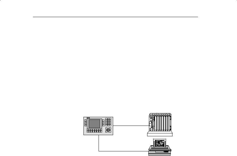
System |
The OP's integrated interfaces permit it to be connected directly to control- |
configuration |
lers. |
|
A printer can also be added for hardcopies and listings. |
OP25, OP35, OP45 |
Controller |
Printer
Planning |
A PC or programmer is used to configure the OP with ProTool (a configuring |
|
program which runs under Windows). |
1-2 |
Equipment Manuel OP25, OP35, OP45 |
Release 04/96 |

Product Description
1.1The Operator Panel at a Glance
OP45
OP35
OP25
Basic Models |
OP25 |
|
OP35 |
OP45 |
|
|
|
|
|
|
|
Models |
Black and white display |
Yes |
|
Yes |
± |
|
Color display |
± |
|
Yes |
Yes |
|
|
|
|
|
|
Display |
Type |
STN-LCD |
|
STN-LCD |
TFT-LCD |
|
|
|
|
|
|
|
Resolution (in pixels) |
320 x 240 |
|
640 x 480 |
640 x 480 |
|
|
|
|
|
|
|
Background illumination |
Yes |
|
Yes |
Yes |
|
|
|
|
|
|
Sealed keyboard |
System keys with fixed |
24 |
|
32 |
32 |
|
functions |
(4 with LED) |
|
(4 with LED) |
(4 with LED) |
|
|
|
|
|
|
|
Function keys with confi- |
24 |
|
36 |
36 |
|
gurable functions |
(18 with LED) |
|
(28 with LED) |
(28 with LED) |
|
Softkeys thereof |
14 |
|
20 |
20 |
|
|
|
|
|
|
|
Function key labels |
Customized labelling with label strips |
|
||
|
|
|
|
|
|
Interfaces |
Serial interfaces for con- |
2 x V.24/TTY |
|
1 x V.24/TTY |
|
|
nection of controller, |
1 x RS 422/RS 485 |
|
1 x V.24 |
|
|
PC/PG, printer |
1 x TTY/RS 422/RS 485 |
|
1 x RS 485 |
|
|
|
|
|
|
|
Equipment Manuel OP25, OP35, OP45 |
1-3 |
Release 04/96 |

Product Description
|
Basic Model |
OP25 |
OP35 |
OP45 |
|
|
|
|
|
|
|
Memory |
|
Flash EPROM for firm- |
1 Mbyte |
2 Mbytes |
± |
|
|
ware and user data |
|
|
|
|
|
|
|
|
|
|
|
Working storage (DRAM) |
2 Mbytes |
4 Mbytes |
8 Mbytes |
|
|
|
|
|
|
|
|
Memory for configuration |
1 Mbyte |
3 Mbytes |
5.5 Mbytes |
|
|
|
|
|
|
Floppy disk drive |
|
± |
Optional |
Yes |
|
|
|
|
|
|
|
Hard disk |
|
|
± |
± |
425 Mbytes |
|
|
|
|
|
|
Special features |
|
Hardware clock (buffered) |
Yes |
Yes |
Yes |
|
|
|
|
|
|
|
|
Relay output |
Yes |
Yes |
± |
|
|
|
|
|
|
|
|
Operation of an external |
± |
± |
Yes |
|
|
MF2 keyboard |
|
|
|
|
|
|
|
|
|
|
|
DOS operation |
± |
± |
Yes |
|
|
|
|
|
|
|
|
Operation of an external |
± |
± |
Yes |
|
|
monitor |
|
|
|
|
|
|
|
|
|
|
|
Module slot for PCMCIA/ |
Yes |
Yes |
± |
|
|
JEIDA cards |
|
|
|
|
|
|
|
|
|
Options |
OP25 |
OP35 |
OP45 |
|
|
|
|
|
|
Direct key module |
Digital outputs, address- |
8 |
16 |
16 |
|
able via either keys or con- |
|
|
|
|
figurable ports |
|
|
|
|
|
|
|
|
Floppy disk drive |
|
± |
3 º drive |
(Included in stan- |
|
|
|
|
dard model) |
|
|
|
|
|
Installation Possible in |
OP25 |
OP35 |
OP45 |
|
|
|
|
Switching cabinets/consoles |
Yes |
Yes |
Yes |
|
|
|
|
19º cabinets/racks |
± |
Yes |
Yes |
|
|
|
|
|
|
|
|
Controllers That Can Be Used |
OP25 |
OP35 |
OP45 |
|
|
|
|
SIMATIC S5 programmable controllers |
Yes |
Yes |
Yes |
|
|
|
(AS 511 only) |
|
|
|
|
SIMATIC S7 automation system |
Yes |
Yes |
± |
|
|
|
|
SIMATIC 500/505 |
Yes |
Yes |
± |
|
|
|
|
PC/AT-compatible computers |
Yes |
Yes |
± |
|
|
|
|
Controllers of other manufacturers |
Yes |
Yes |
± |
|
|
|
|
1-4 |
Equipment Manuel OP25, OP35, OP45 |
Release 04/96 |

Product Description
1.2Process Visualization and Manipulation
|
ªOne picture is worth a thousand wordsº goes the familiar saying. |
|
This is particularly true of machine and system monitoring where it is impor- |
|
tant to provide the operator with clear and easy-to-understand information |
|
about the state of the process. |
Screens |
Process values and process sequences are shown by screens which can con- |
|
tain graphics, texts and values. Process values in a system are often related |
|
in some way. Screens show this relationship and thus represent an image of |
|
the process. |
Full graphic plant |
The OP permits you to represent machines and plants as full graphic |
screens |
screens. This improves operator orientation. |
Bars, curves |
You can show current process values (e.g., filling level and speed) as numeric |
|
values, or symbolically as text or bars. |
|
Curves are a particularly good way to show changeable process values (e.g., |
|
changes in temperature) over a period of time. |
Symbolic graphics |
Symbolic graphics are another way to indicate process values. Symbolic |
|
graphics are graphic elements (i.e., bit maps) which are indicated alternately |
|
to show different process states (e.g., valve open or closed). |
Process manipula- |
The operator can use the OP's integrated keyboard to intervene in the process |
tion |
sequence. |
|
For example, you can control actuators (e.g., valves) by specifying process |
|
values (i.e., setpoints). |
|
Features important to operator control include ease of handling, short training |
|
periods, and a high degree of reliability. |
|
You can configure the structure of the OP operating environment as desired |
|
(i.e., you can tailor operator control to your particular application). |
|
A few features: |
|
Free configurable function keys |
|
Softkeys |
|
Pop-up windows for symbolic entries |
Equipment Manuel OP25, OP35, OP45 |
1-5 |
Release 04/96 |

Product Description
Messages |
Process or machine states (e.g., the current operating mode) are displayed by |
|
the OP as plain-text event messages. |
|
Alarm messages provide information on critical machine states. |
|
Current measured values (e.g., temperatures, speeds, etc.) can also be in- |
|
cluded in the text of event or alarm messages. |
|
Event and alarm messages are stored with date and time in a message buffer. |
|
At the same time, all event and alarm occurrences can be printed (if message |
|
logging is switched on and a printer is connected). |
Information texts |
Information texts can be configured. You can use them to give the operator |
|
additional information which will help him/her to correct a malfunction. |
Recipes |
Complete blocks of machine data can be stored as recipes on the OP. |
|
The structure of a recipe is specified during the configuring phase. It makes |
|
no difference whether the recipes are ªreal recipesº or only piece number |
|
specifications, traversing paths or temperature progressions. |
|
You can change or redefine recipe data directly on the OP. |
Password protec- |
The OP offers password protection. Each operator can be assigned a differ- |
tion |
ent password. A password level can then be used to enable or disable each |
|
operator's access to special operating functions. This prevents incorrect en- |
|
tries and improves system security. |
Multiple languages |
All messages and texts for screens can be stored in the OP in up to three dif- |
|
ferent languages. |
|
This permits international use even when operating personnel speak different |
|
languages. |
PG functions |
The ªSTATUS/FORCE VARIABLEº PG functions are available for testing |
|
and trouble-shooting. They can be used on the OP to specify and change |
|
address areas in the controller. This makes on-site troubleshooting fast even |
|
without a programmer. |
1-6 |
Equipment Manuel OP25, OP35, OP45 |
Release 04/96 |

Functionality |
|
|
2 |
||
|
The functions of the operating panels are listed below. The numerical values |
||||
|
contained in the tables are the maximum values that can be managed by an |
||||
|
OP and are limited possibly only by the size of the user memory. |
||||
|
|
|
|
|
|
|
Functions |
OP25 |
OP35 |
OP45 |
|
|
|
|
|
|
|
Event messages |
|
Number |
2000 |
|
|
|
|
|
|
|
|
|
|
Indication |
In message line/message window |
||
|
|
|
|
|
|
|
|
View all queued events |
On message page |
|
|
|
|
|
|
|
|
|
|
Length of message text (in char- |
2 x 35 |
70 |
70 |
|
|
acters) |
|
|
|
|
|
|
|
|
|
|
|
Lines per message |
2 |
1 |
1 |
|
|
|
|
|
|
|
|
Process values in message text |
8 |
|
|
|
|
|
|
|
|
Alarm messages |
|
Number |
2000 |
|
|
|
|
|
|
||
|
|
Indication |
In message line/message window |
||
|
|
|
|
||
|
|
Indication type |
1st value/last value (can be selected) |
||
|
|
|
|
|
|
|
|
View all queued alarms |
On message page |
|
|
|
|
|
|
|
|
|
|
Length of message text (in char- |
2 x 35 |
70 |
70 |
|
|
acters) |
|
|
|
|
|
|
|
|
|
|
|
Lines per message |
2 |
1 |
1 |
|
|
|
|
|
|
|
|
Process values in message text |
8 |
|
|
|
|
|
|
|
|
|
|
Acknowledge single alarm mes- |
Yes |
|
|
|
|
sages |
|
|
|
|
|
|
|
||
|
|
Acknowledge several alarm mes- |
Yes, 16 acknowledgement groups |
||
|
|
sages simultaneously |
|
|
|
|
|
|
|
|
|
Message logging |
|
Logged on a printer |
Yes |
|
|
|
|
|
|
|
|
Message buffer |
|
Capacity |
512 message occurrences |
|
|
|
|
|
|
|
|
|
|
Look at buffered event messages/ |
On puffer page |
|
|
|
|
alarm messages |
|
|
|
|
|
|
|
|
|
|
|
Delete |
Yes |
|
|
|
|
|
|
|
|
|
|
Buffer overflow warning |
Yes |
|
|
|
|
|
|
|
|
|
|
Forced printout for buffer over- |
Yes |
|
|
|
|
flow |
|
|
|
|
|
|
|
|
|
Equipment Manuel OP25, OP35, OP45 |
2-1 |
Release 04/96 |

Functionality
|
Functions |
OP25 |
|
OP35 |
|
OP45 |
|
|
|
|
|
|
|
|
|
Message acquisition |
|
Time of occurrence |
Date/time |
|
|
|
|
|
|
|
|
||||
|
|
Message status |
Arriving, departing, acknowledged |
||||
|
|
|
|
|
|
|
|
Screens |
|
Indicate |
Yes |
|
|
|
|
|
|
|
|
|
|
|
|
|
|
Print (hardcopy) |
Yes |
|
|
|
|
|
|
|
|
|
|||
|
|
Static screen elements |
Static full graphics |
|
|||
|
|
|
Fixed text |
|
|
|
|
|
|
|
Semigraphic characters |
|
|||
|
|
|
|
|
|
|
|
|
|
Input/output elements |
Input fields |
|
|
|
|
|
|
|
Output fields |
|
|
|
|
|
|
|
Combined input/output fields |
|
|||
|
|
|
Symbolic input |
|
|
|
|
|
|
|
(pop-up window) |
|
|||
|
|
|
Symbolic output |
|
|||
|
|
|
(graphics/text) |
|
|
|
|
|
|
|
Bars |
|
|
|
|
|
|
|
Curves |
|
|
|
|
|
|
|
|
|
|||
|
|
Operator prompting |
Icons for softkey functions |
|
|||
|
|
|
|
|
|
|
|
|
|
Fixed window |
Yes |
|
|
|
|
|
|
|
|
|
|
|
|
Limit value monitoring |
|
For inputs/outputs |
Yes |
|
|
|
|
|
|
|
|
|
|
|
|
Conversion functions |
|
For inputs/outputs |
Linear |
|
|
|
|
|
|
|
Square |
|
|
|
|
|
|
|
|
|
|
|
|
Fonts |
|
Loadable fonts per language |
3 |
|
|
|
|
|
|
|
|
|
|
|
|
|
|
Fonts not dependent on language |
1 |
|
|
|
|
|
|
(with semigraphic characters) |
|
|
|
|
|
|
|
|
|
|
|
|
|
|
|
Character sizes in pixels |
8 x 8 to 64 x 64 |
|
|
|
|
|
|
|
|
|
|||
Text attributes |
|
Display |
Flashing, inverse, underlined |
|
|||
|
|
|
|
|
|||
|
|
Printer |
Bold, italics, underlined |
|
|||
|
|
|
|
|
|
|
|
Information texts |
|
Lines/characters |
7/35 |
|
|
|
|
|
|
|
|
|
|
|
|
|
|
For messages |
Yes |
|
|
|
|
|
|
|
|
|
|
|
|
|
|
For input fields |
Yes |
|
|
|
|
|
|
|
|
|
|
|
|
|
|
For screens |
Yes |
|
|
|
|
|
|
|
|
|
|
|
|
Password protection |
|
Number of passwords |
50 |
|
|
|
|
|
|
Password levels |
9 |
|
|
|
|
|
|
|
|
|
|
|
|
2-2 |
Equipment Manuel OP25, OP35, OP45 |
Release 04/96 |

Functionality
Functions |
OP25 |
OP35 |
OP45 |
||
|
|
|
|
|
|
Recipes |
Number |
255 |
|
|
|
|
|
|
|
|
|
|
Data records per recipe |
500 |
|
|
|
|
|
|
|
|
|
|
Entries per data record |
500 |
|
|
|
|
|
|
|
|
|
|
Save data records (set up) |
Controller/OP storage medium |
|||
|
|
|
|
|
|
|
Load data records |
Storage medium OP/controller |
|||
|
|
|
|
|
|
|
Delete data records |
In storage medium |
|
||
|
|
|
|
|
|
|
Change data records (edit) |
In storage medium |
|
||
|
|
|
|
|
|
|
Transfer current values |
Controller OP |
|
||
|
|
OP controller |
|
||
|
|
|
|
|
|
|
Transfer data records |
Data medium OP |
|
||
|
|
OP data medium |
|
||
|
|
|
|
|
|
|
Parameter records |
Yes |
|
|
|
|
|
|
|
|
|
Print functions |
Hardcopy of the contents of the |
|
|
|
|
|
display |
|
|
|
|
|
Character mode (ASCII) |
Yes |
|
|
|
|
|
|
|
||
|
Graphic mode |
Yes |
|
|
|
|
|
|
|
||
|
|
|
|
|
|
|
Direct message logging |
Yes |
|
|
|
|
|
|
|
|
|
|
Screen printout in character mode |
Yes |
Yes |
± |
|
|
(ASCII) |
|
|
|
|
|
|
|
|
|
|
Data backup |
Backup/restore function for |
Yes |
Yes |
± |
|
|
PCMCIA/JEIDA cards |
|
|
|
|
|
|
|
|
|
|
Online language switchover |
Number of languages |
3 |
|
|
|
|
|
|
|
|
|
PG functions |
For SIMATIC S5 |
Yes |
Yes |
Yes |
|
(Status/force variable) |
|
|
|
|
|
For SIMATIC S7 |
Yes |
Yes |
Yes |
||
|
|||||
|
|
|
|
|
|
Loop±through operation |
For PG or additional TD/OP |
Yes |
Yes |
No |
|
|
(only with SIMATIC S5 and |
|
|
|
|
|
AS 511 protocol) |
|
|
|
|
|
|
|
|
|
|
Display |
Setting for display brightness/ |
Yes |
Yes |
± |
|
|
contrast |
|
|
|
|
|
|
|
|
|
|
|
Blanking circuit |
Yes |
Yes |
± |
|
|
|
|
|
|
|
Connection to PLC |
SIMATIC S5-AS511 |
Yes |
Yes |
Yes |
|
|
SIMATIC S5-FAP |
Yes |
Yes |
± |
|
|
SIMATIC S5-L2-DP |
Yes |
Yes |
No 2 |
|
|
SIMATIC S7-MPI |
Yes |
Yes |
± |
|
|
SIMATIC S7-PPI |
Yes |
Yes |
± |
|
|
SIMATIC 500/505 |
Yes |
Yes |
± |
|
|
Free Serial |
Yes |
Yes |
± |
|
|
Allen Bradley |
Yes 3 |
Yes 3 |
± |
|
|
Mitsubishi |
Yes 3 |
Yes 3 |
± |
|
|
Telemecanique |
Yes 3 |
Yes 3 |
± |
|
2)The immunity to interference cannot be guaranteed on account of the hardware characteristics of the OP45
3)Driver available as an option
Equipment Manuel OP25, OP35, OP45 |
2-3 |
Release 04/96 |

Functionality
Equipment Manuel OP25, OP35, OP45
Release 04/96
FUNCTIONS OF THE
OPERATOR PANEL
3Using the OP
4Screens
5Messages
6Recipes
7Print Functions
8Password Protection
9Status/Force Variable with the OP
Part II
Equipment Manuel OP25, OP35, OP45 |
ii-i |
Release 04/96 |

Equipment Manuel OP25, OP35, OP45
Release 04/96

Using the OP |
3 |
Overview |
Processes (e.g., a machine tool, mixing station or similar) are displayed on the |
|||||||||||||
|
OP with screens. The processes can also be manipulated. |
|||||||||||||
Screen section |
One screen takes up the entire display. An example of a possible layout is |
|||||||||||||
|
shown below. |
|||||||||||||
|
|
|
|
|
|
|
|
|
|
|
|
|
|
Fixed window |
|
|
|
|
|
|
|
|
|
|
|
|
|
|
|
|
|
|
|
|
|
|
|
|
|
|
|
|
|
Main screen area |
|
|
|
|
|
|
|
|
|
|
|
|
|
|
|
|
|
|
|
|
|
|
|
|
|
|
|
|
|
Icons for softkey |
|
|
|
|
|
|
|
|
|
|
|
|
|
|
functions |
|
|
|
|
|
|
|
|
|
|
|
|
|
|
|
|
Figure 3-1 Screen layout for the OP25 |
|||||||||||||
Fixed window |
The fixed window provides the operator with a continuous stream of important |
|||||||||||||
|
process variables regardless of which screen is open at the moment. |
|||||||||||||
Main screen area |
The main screen area contains the actual contents of the currently opened |
|||||||||||||
|
screen. |
|||||||||||||
|
Additional windows (e.g., message windows, help windows and pop-up win- |
|||||||||||||
|
dows) are faded in over the main screen area and the fixed window. |
|||||||||||||
Icons |
Icons symbolize softkey functions related to specific screens. |
|||||||||||||
Equipment Manuel OP25, OP35, OP45 |
3-1 |
Release 04/96 |

Using the OP
3.1Keyboard
Overview |
The keyboard of the OP is equipped with two blocks of keys: |
|||
|
|
The function keys/softkeys |
||
|
|
The system keys |
|
|
Function keys/ |
A function key always triggers the same action in the OP or controller (i.e., |
|||
softkeys |
global significance for the OP) regardless of which screen is currently open. |
|||
|
A few possible actions are listed below. |
|||
|
|
Open a screen |
|
|
|
Indicate the current alarm messages |
|||
|
Start a hardcopy of a screen |
|||
|
Indicate the time window |
|||
|
The term softkey means that function keys can have a meaning related to the |
|||
|
currently open screen (i.e., local). |
|||
|
The function of a softkey can vary from screen to screen. When a screen is |
|||
|
open, a softkey's function is shown by an icon in the margin of the monitor |
|||
|
screen. |
|
||
|
The following keys can have softkey functionality: |
|||
|
|
For OP25: |
F1 to F14 |
|
|
|
For OP35/OP45: F1 to F20 |
||
Repeat function |
The repeat function activates when a key is repeatedly pressed. |
|||
(for OP45 only) |
|
|
|
|
|
|
|
|
|
Note
Do not press several keys on the OP45 at the same time. This can cause incorrect entries.
3-2 |
Equipment Manuel OP25, OP35, OP45 |
Release 04/96 |
Using the OP
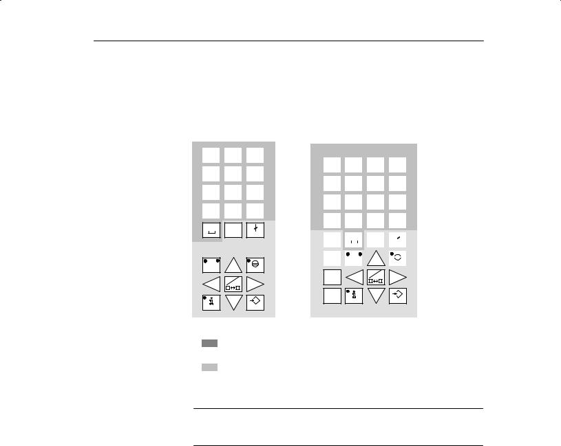
System keys |
The system keys are used to make entries on the OP. |
|
Figure 3-2 shows the system keyboard for the OP25 and OP35/OP45. |
OP25
A |
B |
|
C |
D |
|
E |
F |
|
7 |
|
|
8 |
|
|
9 |
|
|
|
|
|
|
|
|
|
|
|
|
|
|
|
|
G |
H |
|
I |
J |
|
K |
L |
|
4 |
|
|
5 |
|
|
6 |
|
|
|
|
|
|
|
|
|
|
|
|
|
|
|
|
M |
N |
|
O |
P |
|
Q |
R |
|
1 |
|
|
2 |
|
|
3 |
|
|
|
|
|
|
|
|
|
|
|
|
|
|
|
|
S |
T |
|
U |
V |
|
W |
X |
|
. |
|
|
0 |
|
|
+/± |
|
|
|
|
|
|
|
|
Y Z INS
DEL
ESC
A±Z
ACK
A±Z |
HELP |
ENTER |
OP35/OP45
A |
B |
|
C |
D |
|
E |
F |
|
G |
H |
|||||
/ |
|
|
7 |
|
|
|
8 |
|
|
9 |
|
|
|||
|
|
|
|
|
|
|
|
|
|
|
|
|
|
|
|
|
|
|
|
|
|
|
|
|
|
|
|
|
|
|
|
I |
J |
|
K |
L |
|
M |
N |
|
O |
P |
|||||
* |
|
|
4 |
|
|
|
5 |
|
|
6 |
|
|
|||
|
|
|
|
|
|
|
|
|
|
|
|
|
|
|
|
|
|
|
|
|
|
|
|
|
|
|
|
|
|
|
|
Q |
R |
|
S |
T |
|
U |
V |
|
W |
X |
|||||
± |
|
|
1 |
|
|
|
2 |
|
|
3 |
|
|
|||
|
|
|
|
|
|
|
|
|
|
|
|
|
|
|
|
|
|
|
|
|
|
|
|
|
|
|
|
|
|||
Y |
Z |
|
: |
|
|
\ |
|
= |
, |
|
( |
|
|
|
) |
+ |
|
|
. |
|
|
|
0 |
|
|
+/± |
|
||||
|
|
|
|
|
|
|
|
|
|
|
|
|
|
|
|
|
|
|
|
|
|
|
|
|
|
|
|
|
|
|
|
TAB |
|
|
|
|
|
|
|
INS |
|
|
|
|
|
|
|
|
|
|
|
|
|
|
DEL |
|
|
|
|
|
|
|
|
|
|
|
|
|
|
|
|
|
ESC |
|
|||||
|
|
|
|
|
|
|
|
|
|
|
|||||
|
|
|
|
|
|
|
|
|
|
|
|
||||
|
|
|
|
|
|
|
|
|
|
|
|
|
|
|
|
ALT |
|
|
A±Z |
|
|
|
|
|
|
|
|
|
|
||
|
|
|
|
|
|
|
|
|
|
|
|
||||
A±Z |
|
|
|
|
|
|
|
ACK |
|
||||||
CTRL |
A±Z |
|
|
SHIFT |
|
HELP |
ENTER |
= Input keys for numeric and alphanumeric characters
= Control keys
Figure 3-2 Assignment of the system keys
Note
The TAB, ALT, CTRL and SHIFT keys of the OP35 have no function.
Equipment Manuel OP25, OP35, OP45 |
3-3 |
Release 04/96 |

Using the OP
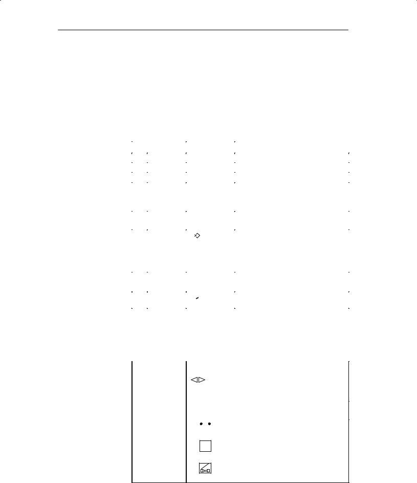
Key functions |
The control keys of the OP have the following functions: |
|||
|
|
|
|
|
|
|
|
Key |
Description |
|
|
|
|
|
|
|
|
Shift key |
This key is used to shift the input keys from numeric to |
|
|
A±Z |
||
|
|
|
alphanumeric. |
|
|
|
|
|
|
|
|
|
|
The key is equipped with two LEDs which indicate the |
|
|
|
|
current status. |
|
|
|
|
No LED is on. |
|
|
|
|
Numeric assignment of the input keys is active. |
|
|
|
|
Alphanumeric assignment of the input keys becomes |
|
|
|
|
active when this key is pressed once. |
|
|
|
|
One of the two LEDs (i.e., left or right) is on. |
|
|
|
|
Left or right alphanumeric assignment of the input |
|
|
|
|
keys is active. |
|
|
|
|
Input key assignment alternates between the left and |
|
|
|
|
right alphanumeric assignment each time this key is |
|
|
|
|
pressed. |
A±Z |
|
Switches the active window (OP25/OP35 only) |
|
|
Switch from alphanumeric assignment of the input |
|
|
keys back to numeric assignment |
|
|
INS |
|
|
Activates edit mode (OP25/OP35 only) |
|||
|
DEL |
|
|
Deletes/inserts single characters |
||||
|
|
|
|
|
|
|
|
|
|
|
|
|
|
|
|
Cancel key |
This key cancels already started actions. Some examples |
|
|
|
|
|
|
|
||
|
|
|
|
|
|
|||
|
ESC |
|
|
are listed below. |
||||
|
|
|
|
|
|
|
|
Delete an already entered character for a value input |
|
|
|
|
|
|
|
|
Delete a queued system message |
|
|
|
|
|
|
|
Acknow- |
This key acknowledges the currently indicated alarm |
|
|
|
|
|
|
|
||
|
|
|
|
|
|
|||
|
ACK |
|
ledgement |
message or all messages of an acknowledgement group. |
||||
|
|
|
|
|
|
|||
|
|
|
|
|
|
|
key |
The LED remains on as long as an unacknowledged |
|
|
|
|
|
|
|
|
alarm message is queued. |
|
|
|
|
|
|
|
|
|
|
|
|
|
|
|
|
Info key |
This key is used to open a window containing a help text |
|
|
|
|
|
|
|
||
|
|
|
|
|
|
|
||
|
|
HELP |
|
for the selected object (e.g., message, input field). |
||||
|
|
|
|
|
|
|
|
The LED goes on when a help text is available for the |
|
|
|
|
|
|
|
|
selected object. |
|
|
|
|
|
|
|
|
The help window is closed by pressing any key. |
|
|
|
|
|
|
|
|
|
|
|
|
|
|
|
|
Apply key |
Accept and exit an entry |
|
|
|
|
|
|
|
||
|
ENTER |
|||||||
|
|
Open the pop-up window for a symbolic entry |
||||||
|
|
|
|
|
|
|
|
|
|
|
|
|
|
|
|
Cursor keys |
Move the cursor to the individual input fields in a |
|
|
|
|
|
|
|
|
screen |
|
|
|
|
|
|
|
|
Move the cursor within an input field |
|
|
|
|
|
|
|
|
Select an entry from the message buffer |
|
|
|
|
|
|
|
|
Select a value from the pop-up window |
3-4 |
Equipment Manuel OP25, OP35, OP45 |
Release 04/96 |

Using the OP
3.2Input/Output Fields
Overview |
The screens on the OP contain different types of input/output fields. |
|
|
|
Numeric fields (digital or analog) |
|
|
String fields |
|
|
Symbolic fields |
|
Values can be entered on the OP in these input fields which are then transferred |
|
|
to the controller. |
|
Procedure |
The basic procedure for entering values on the OP is described below. |
|
|
1. |
Using the cursor keys, position the cursor on the desired input field. |
|
2. |
Enter the value. The method of entry varies depending on the type of field. |
|
|
See the following subsections for information on handling the individual |
|
|
fields. |
|
3. |
Confirm the entry with with ENTER key. |
Correcting/cancel- |
The following methods of correction are available before the entry is applied. |
|
ing entries |
|
Using the INS/DEL key, insert/delete single characters where the cursor is |
|
||
|
|
positioned. Then use the ENTER key to confirm the correct value. |
|
|
Cancel the entry with the ESC key. |
|
|
The original value is then automatically rewritten in the field. Enter the |
|
|
correct value, and confirm with the ENTER key. |
Edit mode |
An edit function is available on the OP25/35. This edit function can be used to |
|
(OP25/35 only) |
edit entries which have already been applied. |
|
|
1. |
Position the cursor on the desired input field. |
|
2. |
Activate edit mode by pressing the INS/DEL key. |
|
|
In contrast to input mode, the indicated value is retained. |
|
3. |
Move the cursor to the appropriate position of the input field. |
|
4. |
Using the INS/DEL key, insert/delete characters where the cursor is posi- |
|
|
tioned. |
|
5. |
Confirm the entry with the ENTRY key. |
|
|
The entry can be canceled with the ESC key. The old value is indicated |
|
|
again. |
Equipment Manuel OP25, OP35, OP45 |
3-5 |
Release 04/96 |
Using the OP
3.2.1Numeric Fields
The shape of the cursor changes in input mode. Input starts at the right-hand edge of the input field. Digits are shifted to the left similar to a pocket calculator.
Entry |
To make entries in a numeric field, proceed as follows: |
||||||||||
|
|
|
|
|
|
|
|
|
|
|
|
|
|
Step |
|
|
|
|
Key |
|
|
Description |
|
|
|
|
|
|
|
|
|
|
|
|
|
|
1 |
Enter deci- |
|
0 |
to |
9 |
|
|
|||
|
|
mal value |
|
|
|
||||||
|
|
|
|
|
|
|
|
|
|||
|
|
|
|
|
|
|
|
|
|||
|
|
|
|
|
|
|
|
|
|
|
|
|
|
|
|
+/± |
, |
|
. |
|
|
||
|
|
|
|
|
|
|
|
||||
|
|
|
|
|
|
|
|
|
|
|
|
|
|
Enter |
|
|
|
|
|
|
|
|
The characters A to F must be entered in |
|
|
|
AS B |
to |
|
E F |
|
||||
|
|
hexadecimal |
|
|
|
|
|
|
|
alpha mode. |
|
|
|
|
|
|
|
|
|
|
|
||
|
|
value |
|
0 |
to |
|
9 |
|
|
||
|
|
|
|
|
|
|
|
|
|
|
|
|
|
|
|
|
|
|
|
|
|
|
|
|
|
|
|
|
|
|
|
|
|
|
|
|
|
Enter digital |
|
|
|
|
|
|
|
|
|
|
|
|
S 0 |
, |
|
1 |
|
|
|||
|
|
value |
|
|
|
|
|
|
|
|
|
|
|
|
|
|
|
|
|
|
|
|
|
|
|
|
|
|
|
|
|
|
|
|
|
|
2 |
Apply entry |
|
|
|
|
|
|
|
|
The entered value becomes valid. |
|
|
|
|
|
|
|
|
|
|||
|
|
ENTER |
|
|
|
|
|||||
|
|
|
|
|
|
|
|
The entry becomes invalid if the en- |
|||
|
|
|
|
|
|
|
|
|
|
|
|
|
|
|
|
|
|
|
|
|
|
|
tered value violates a configured limit |
|
|
|
|
|
|
|
|
|
|
|
value or an incorrect entry is made. |
|
|
|
|
|
|
|
|
|
|
|
The ªoldº value is retained. |
|
|
Or |
|
|
|
|
|
|
|
|
|
|
|
Cancel entry |
|
|
|
|
|
|
|
|
The ªoldº value becomes valid again. |
|
|
|
|
|
|
|
|
|
|
||
|
|
|
|
|
|
|
|
|
|
||
|
|
|
|
ESC |
|
|
|
|
|
||
|
|
|
|
|
|
|
|
|
|
|
|
Correction |
If you have made a mistake and have not yet applied the entry, proceed as fol- |
|||||
|
lows: |
|
|
|
|
|
|
|
|
|
|
|
|
|
IF ... |
|
|
|
THEN ... |
|
|
|
|
|
|
|
|
|
|
|
|
|
Position the cursor on the digit and over- |
|
|
Wrong digit |
|
|
write. |
||
|
|
|
|
|
||
|
|
|
|
|
(The cursor remains on this position.) |
|
|
|
|
|
|
|
|
|
One digit too |
|
|
|
Deletes the digit at the cursor position and |
|
|
|
INS |
||||
|
many |
|
DEL |
consolidates the input from the left. |
||
|
|
|
|
|||
|
|
|
|
|
|
|
|
1. |
|
|
|
Switch to alpha mode. |
|
|
|
|
A±Z |
|||
|
|
|
|
|
|
|
|
One digit too few |
|
|
|
|
|
|
|
|
|
|
||
2. |
INS |
Inserts a blank where the cursor is positioned and |
|
DEL |
shifts the entry to the left starting at the cursor |
|
|
|
|
|
position. |
3. |
A±Z |
Shift back to numeric assignment of the input keys. |
|
4.Overwrite blank.
3-6 |
Equipment Manuel OP25, OP35, OP45 |
Release 04/96 |

Using the OP
3.2.2String Fields
Both numeric characters (i.e., digits) and alphanumeric characters (i.e., letters of the alphabet) can be entered in a string field. Strings may also contain blanks.
The cursor changes shape in input mode. The entry starts at the left edge of the input field. The cursor jumps one position to the right each time a character is entered.
Entry |
To make entries in a string field, proceed as follows: |
||||||||||
|
|
|
|
|
|
|
|
|
|
|
|
|
|
Step |
|
|
|
|
|
Key |
|
|
Description |
|
|
|
|
|
|
|
|
|
|
|
|
|
1 |
Enter digits |
|
0 |
to |
9 |
|
If necessary, switch back from alpha mode. |
|||
|
|
|
|
|
|
||||||
|
|
|
|
|
|
|
|
|
|
|
|
|
|
|
|
|
|
|
|
|
|
|
|
|
|
|
|
|
|
|
|
|
|
|
|
|
|
|
|
+/± |
, |
. |
|
|
|||
|
|
|
|
|
|
|
|||||
|
|
|
|
|
|
|
|
|
|
|
|
|
|
Enter letters |
|
|
|
|
|
|
|
|
Switch to alpha mode. |
|
|
|
A±Z |
|
|
|
|||||
|
|
|
|
|
|
|
|
|
|
|
|
|
|
|
|
|
|
|
|
|
|
|
|
|
|
|
|
AS B |
to |
Y Z |
|
|
|||
|
|
|
|
|
|
|
|
|
|
|
|
|
|
|
|
|
|
|
|
|
|
|
|
|
2 |
Apply entry |
|
|
|
|
|
|
|
|
The entered string becomes valid. |
|
|
|
|
|
|
|
|
|
|||
|
|
ENTER |
|
|
|
||||||
|
|
Or |
|
|
|
|
|
|
|
|
Switch back from alpha mode4 |
|
|
|
|
|
|
|
|
|
|
||
|
|
|
|
|
|
|
|
|
|
|
|
|
|
Cancel entry |
|
|
|
|
|
|
|
|
The input cursor is deleted. |
|
|
|
|
|
|
|
|
|
|
||
|
|
|
|
|
|
|
|
|
|
||
|
|
|
|
|
ESC |
|
|
|
Switch back from alpha mode1 |
||
|
|
|
|
|
|
|
|
|
|
|
|
|
|
|
|
|
|
|
|
|
|
|
The ªoldº string becomes valid again. |
Correction |
If you have made a mistake and have not yet accepted the entry, proceed as |
||||||
|
follows: |
|
|
|
|
|
|
|
|
|
|
|
|
|
|
|
IF ... |
|
|
|
|
|
THEN ... |
|
|
|
|
|
|
|
|
|
|
|
|
|
|
Position the cursor on the character and |
|
|
Wrong character |
|
|
|
|
overwrite. |
|
|
|
|
|
|
|
|
|
|
|
|
|
|
|
(The cursor jumps one position to the right |
|
|
|
|
|
|
|
after the overwrite.) |
|
|
|
|
|
|
|
|
|
|
One character too |
|
|
|
Deletes the character at the cursor position |
||
|
|
INS |
|||||
|
many |
|
DEL |
|
and consolidates the input from the right. |
||
|
|
|
|
|
|||
|
|
|
|
|
|||
|
|
|
|
|
|
|
|
|
|
1. |
|
|
|
|
Switch to alpha mode. |
|
|
|
|
A±Z |
|
||
|
|
|
|
|
|
|
|
|
One character too |
|
|
|
|
|
|
|
|
|
|
|
|
|
|
|
few |
2. |
|
|
|
|
Inserts a blank where the cursor is |
|
|
|
INS |
|
|||
|
|
|
DEL |
||||
|
|
|
|
positioned and shifts the entry to the |
|||
|
|
|
|
|
|
|
|
|
|
|
|
|
|
|
|
|
|
|
|
|
|
|
right starting at the cursor position. |
3.Overwrite blank.
4)Not applicable to OP45
Equipment Manuel OP25, OP35, OP45 |
3-7 |
Release 04/96 |
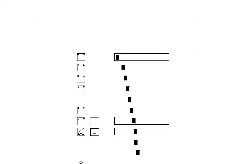
Using the OP
Example of a |
You want to enter ªvalve 05º. Proceed as follows: |
|
string entry |
|
|
|
Key |
Display |
|
|
|
A±Z
A±Z
A±Z
A±Z
A±Z
|
U |
V |
|
V |
, |
|
|
|
|
|
|
|
|
|
|
|
|
|
|
|
E |
F |
|
VA |
, |
|
|
|
|
|
|
|
|
|
|
|
|
|
|
|
|
|
|
|
, |
M |
N |
|
VAL |
|
|
|
||
|
|
|
|
|
|
|
|
|
|
|
|
|
|
|
|
S |
T |
|
VALV |
|
|
|
|
|
|
|
|
|
|
|
|
|
|
|
|
|
|
|
|
|
I |
J |
|
VALVE |
, |
|
|
|
|
|
|
|
|
|
|
|
|
|
|
A±Z |
K |
L |
VALVE |
, |
|
||
|
|
|
A±Z |
, |
VALVE |
|
||
|
|
|
|
|
|
VALVE |
0 |
0 |
|
||||
|
|
|
|
|
|
|
|
|
|
|
|
|
|
|
|
|
|
5 |
|
VALVE |
05 |
||
|
|
|
|
|
|
|
|
|
Apply entry. |
||
|
|
|
|||
|
|
|
|||
ENTER |
|||||
3-8 |
Equipment Manuel OP25, OP35, OP45 |
Release 04/96 |
Loading...