

Page 1
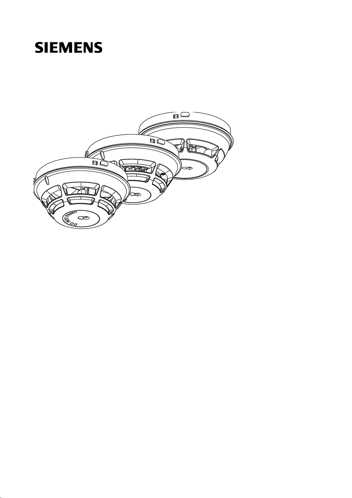
OH720, OP720, HI720, HI722
Automatic fire detectors
Technical Manual
A6V10212047_m_en_--
Building Technologies
2015
-05-04
Control Products and Systems
Page 2

Legal notice
2
Building Technologies
A6V10212047_m_en_--
Fire Safety
Legal notice
Technical specifications and availability subject to change without notice.
ransmittal, reproduction, dissemination and/or editing of this document as well as
T
utilization of its contents and communication thereof to others without express
authorization are prohibited. Offenders will be held liable for payment of damages.
All rights created by patent grant or registration of a utility model or design patent
are reserved.
ssued by:
I
Siemens Switzerland Ltd.
Building Technologies Division
International Headquarters
Gubelstrasse 22
CH-6301 Zug
Tel. +41 41 724-2424
www.siemens.com/buildingtechnologies
Edition: 2015-05-04
Document ID: A6V10212047_m_en_--
© Siemens Switzerland Ltd, 2008
| 64
2015-05-04
Page 3

64
Building Technologies A6V10212047_m_en_--
Fire Safety
Table of contents
1 About this document ................................................................................... 5
1.1 Applicable documents ..................................................................................... 7
1.2 Download center ............................................................................................. 7
1.3 Technical terms ............................................................................................... 7
1.4 History of changes........................................................................................... 8
2 Safety ....................................................................................................... 10
2.1 Safety instructions ......................................................................................... 10
2.2 Safety regulations for the method of operation ............................................. 12
2.3 Standards and directives complied with ........................................................ 14
2.4 Release Notes ............................................................................................... 14
3 Structure and function ............................................................................... 15
3.1 Overview ....................................................................................................... 15
3.1.1 Details for ordering ........................................................................ 15
3.1.2 Product version ES ........................................................................ 16
3.2 Point detector ................................................................................................ 17
3.2.1 Multi-sensor smoke detector .......................................................... 17
3.2.2 Smoke detector .............................................................................. 18
3.2.3 Heat detector ................................................................................. 19
3.3 Function ......................................................................................................... 20
3.3.1 Parameter sets............................................................................... 20
3.3.2 Danger levels ................................................................................. 20
3.3.3 Diagnosis levels ............................................................................. 20
3.3.4 Line separator ................................................................................ 21
3.3.5 Internal alarm indicator in the case of ES <10 ............................... 21
3.3.6 Extended flashing behavior of alarm indicators in the case of
ES ≥10 ........................................................................................... 22
3.3.7 Connection for external alarm indicators ....................................... 23
3.3.8 Test mode ...................................................................................... 23
3.3.9 Behavior in degraded mode ........................................................... 24
3.3.10 Line tester ...................................................................................... 24
3.4 Mechanical setup .......................................................................................... 25
3.5 Accessories ................................................................................................... 26
3.5.1 Detector base with loop contact DB721 ........................................ 26
3.5.2 Detector base DB722 .................................................................... 26
3.5.3 Detector base DB720 .................................................................... 27
3.5.4 Sounder base DBS720 .................................................................. 27
3.5.5 Designation plate FDBZ291 ........................................................... 27
3.5.6 Detector base seal RS720 ............................................................. 27
3.5.7 Base attachment BA720 ................................................................ 28
3.5.8 Base attachment wet BA721 ......................................................... 28
3.5.9 Designation plate DBZ1193A ........................................................ 28
3.5.10 Detector heating unit FDBH291 ..................................................... 28
3 |
2015-05-04
Page 4

Building Technologies A6V10212047_m_en_--
Fire Safety
4
3.5.11 Protective cage DBZ1194 .............................................................. 29
3.5.12 Detector locking device LP720 ...................................................... 29
3.5.13 Micro terminal DBZ1190-AA .......................................................... 29
3.5.14 Connection terminal DBZ1190-AB ................................................. 30
4 Planning .................................................................................................... 31
4.1 Compatibility .................................................................................................. 31
4.2 Multi-sensor smoke detector ......................................................................... 31
4.2.1 Parameter sets ............................................................................... 31
4.2.2 Specifications ................................................................................. 32
4.3 Smoke detector ............................................................................................. 32
4.3.1 Parameter sets ............................................................................... 32
4.3.2 Specifications ................................................................................. 33
4.4 Heat detector ................................................................................................. 33
4.4.1 Parameter sets ............................................................................... 33
4.4.2 Specifications ................................................................................. 34
5 Mounting / Installation ................................................................................ 35
5.1 Required space ............................................................................................. 35
5.2 Detector base DB72x .................................................................................... 36
5.3 Sounder base DBS720.................................................................................. 38
5.4 Detector base seal RS720 ............................................................................ 39
5.5 Base attachment BA720................................................................................ 40
5.6 Base attachment wet BA721 ......................................................................... 41
5.7 Detector locking device LP720 ...................................................................... 44
5.8 Designation plate FDBZ291 .......................................................................... 45
5.9 Cable entry .................................................................................................... 46
5.9.1 Auxiliary terminals DBZ1190-AA/-AB ............................................ 47
5.10 Detector lines ................................................................................................ 47
5.10.1 Connection diagram, addressed .................................................... 47
5.11 Detector dust cap .......................................................................................... 49
5.12 Detector heating unit FDBH291 .................................................................... 50
5.12.1 Installation of the detector heating unit .......................................... 50
5.12.2 Connection of the detector heating unit ......................................... 51
6 Commissioning .......................................................................................... 52
6.1 Commissioning on the C-NET ....................................................................... 52
| 64
7 Maintenance / Repair ................................................................................. 53
7.1 Performance check ....................................................................................... 53
7.2 Testing detectors ........................................................................................... 53
8 Specifications ............................................................................................ 54
8.1 Multi-sensor smoke detector technical data .................................................. 54
8.2 Smoke detector technical data ...................................................................... 56
8.3 Heat detector technical data.......................................................................... 58
8.4 Dimensions .................................................................................................... 60
8.5 Environmental compatibility........................................................................... 60
Index .................................................................................................................. 61
2015-05-04
Page 5

0BAbout this document
8BApplicable documents
1
64
Building Technologies
A6V10212047_m_en_--
Fire Safety
Target group
Activity
Qualification
1 About this document
Goal and purpose
This document contains information on automatic fire detectors. Following the
instructions consistently will ensure that the product can be used safely and without
any problems.
Scope
The document is valid for the following automatic fire detectors:
● OH720
● OP720
● HI720
● HI722
Target groups
The information in this document is intended for the following target groups:
Product Manager ● Is responsible for information
passing between the manufacturer
and regional company.
● Coordinates the flow of information
between the individual groups of
people involved in a project.
Project Manager ● Coordinates the deployment of all
persons and resources involved in
the project according to schedule.
● Provides the information required to
run the project.
Project engineer ● Sets parameters for product
depending on specific national
and/or customer requirements.
● Checks operability and approves
the product for commissioning at the
place of installation.
● Is responsible for troubleshooting.
Installation personnel ● Assembles and installs the product
components at the place of
installation.
● Carries out a performance check
following installation.
● Has obtained suitable specialist
training for the function and for the
products.
● Has attended the training courses
for Product Managers.
● Has obtained suitable specialist
training for the function and for the
products.
● Has attended the training courses
for Project Managers.
● Has obtained suitable specialist
training for the function and for the
products.
● Has attended the training courses
for Product Engineer.
● Has received specialist training in
the area of building installation
technology or electrical installations.
Maintenance personnel ● Carries out all maintenance work.
● Has obtained suitable specialist
● Checks that the products are in
perfect working order.
training for the function and for the
products.
● Searches for and corrects
malfunctions.
Source language and reference document
● The source/original language of this document is German (de).
● The reference version of this document is the international version in English.
The international version is not localized.
5 |
2015-05-04
Page 6

0BAbout this document
8BApplicable documents
1
6
Building Technologies A6V10212047_m_en_--
Fire Safety
ID code
Examples
The 'i' symbol identifies supplementary information and tips for an easier way of
Document identification
The document ID is structured as follows:
ID_ModificationIndex_Language_COUNTRY
-- = multilingual or international
A6V10215123_a_de_DE
A6V10215123_a_en_-A6V10315123_a_--_--
Date format
The date format in the document corresponds to the recommendation of
international standard ISO 8601 (format YYYY-MM-DD).
Conventions for text marking
Markups
Special markups are shown in this document as follows:
⊳ Requirement for a behavior instruction
1.
Behavior instruction with at least two operation sequences
2.
– Version, option, or detailed information for a behavior instruction
⇨ Intermediate result of a behavior instruction
⇨ End result of a behavior instruction
● Numbered lists and behavior instructions with an operation
sequence
[➙ X] Reference to a page number
'Text' Quotation, reproduced identically
<Key> Identification of keys
> Relation sign and for identification between steps in a sequence,
e.g., 'Menu bar' > 'Help' > 'Help topics'
↑ Text Identification of a glossary entry
Supplementary information and tips
working.
| 64
2015-05-04
Page 7
0BAbout this document
8BApplicable documents
1
64
Building Technologies
A6V10212047_m_en_--
Fire Safety
Document ID
Name
You will also find information about search variants and links to mobile
Term
Explanation
1.1 Applicable documents
008115 Installation Detector heating FDBH291
008250 Technical Manual Line tester FDUL221
A6V10200373 Installation Detector base with loop contact DB721, DB722, detector
base DB720, sounder base DBS720, detector base seal RS720,
detector locking device LP720, base attachment BA720
A6V10201731 Installation Detector exchanger DX791, adapter for detector
exchanger FDUD491
A6V10202198 Data sheet Automatic fire detectors OH720, OP720, HI720, HI722
A6V10203222 Data Sheet Testequipment and accessories FDUL221, DX791, RE6,
A6V10229261 List of compatibility (for 'Cerberus™ PRO' product line)
A6V10254740 Operating instructions Solo461 heat detector tester kit RE7T
A6V10406006 Installation Base attachment wet BA721, Detector designation plate
Please also observe the documentation for your fire detection system.
RE7T, RE8ST, RE8STCO, FDUM29x, LE3, StabexHF
DBZ1193A, Protective cage DBZ1194, EMC-protective cage
FDBZ294
1.2 Download center
You can download various types of documents, such as data sheets, installation
instructions, and license texts via the following Internet address:
http://siemens.com/bt/download
Enter the document ID in the 'Find by keyword' input box.
applications (apps) for various systems on the home page.
1.3 Technical terms
AI Alarm indicator
C-NET Addressed detector line
EAI External alarm indicator
ES Product version
IAI Internal alarm indicator
7 |
2015-05-04
Page 8

0BAbout this document
11BHistory of changes
1
8
Building Technologies A6V10212047_m_en_--
Fire Safety
The first edition of a language version or a country variant may, for example, be
Modification index
Edition date
Brief description
1.4 History of changes
The reference document's version applies to all languages into which the reference
document is translated.
version 'd' instead of 'a' if the reference document is already this version.
m
l
k
j
i
h
g
f
e
d
c
b
a
2015-05-04 Information about the extended flashing behavior inserted
2014-10-24 Flashing behavior updated
Additions to the 'Internal alarm indicator' chapter
2014-09-12 Additions to the 'Technical data' chapters
2014-03-04 Change to date format in line with ISO 8601 specifications (yyyy-mm-dd format);
various changes in the 'Specifications' chapter; editorial changes; base attachment
wet BA721, designation plate DBZ1193A, protective cage DBZ1194, EMC-protective
cage FDBZ294, and detector heating unit FDBH291 added, data sheet in 'Applicable
documents' chapter added; 'Download center' chapter added; 'Internal alarm
indicator' chapter revised
10.2011 Detector base DB722 and base attachment BA720 added, marine approval added,
max. operating temperature changed to 55 °C, 'Product version' chapter added
03.2011 Connection diagram corrected
09.2010 FM approvals added
04.2010 New external alarm indicators added, minor editorial changes
09.2009 LPCB approvals added
08.2009 Detector base with loop contact DB721 added
04.2009 Cable cross section for detector base specified and minor editorial changes made
VdS approval and CPD no. added
10.2008 Protection classes changed
09.2008 First edition
The table below shows this document's revision history:
| 64
2015-05-04
Page 9

0BAbout this document
11BHistory of changes
1
64
Building Technologies
A6V10212047_m_en_--
Fire Safety
Modification index
en_--
de_--
fr_--
it_--
es_--
The table below shows the published language versions with the corresponding
modification index:
m X X X X X
l X X X X X
k – X – – –
j X X X X X
i X X X X X
h X X X X X
g X X X X X
f X X X X X
e X X – – –
d X X X X X
c X X X X X
b X X X X X
a X X X X X
X = published
– = no publication with this modification index
9 |
2015-05-04
Page 10
1BSafety
12BSafety instructions
2
10
Building Technologies A6V10212047_m_en_--
Fire Safety
risks of injury
Signal word
Danger level
DANGER
will result directly in death or
serious injury
WARNING
may result in death or serious
injury
CAUTION
slight to
moderately serious injury
2 Safety
2.1 Safety instructions
The safety notices must be observed in order to protect people and property.
The safety notices in this document contain the following elements:
● Symbol for danger
● Signal word
● Nature and origin of the danger
● Consequences if the danger occurs
● Measures or prohibitions for danger avoidance
This is the symbol for danger. It warns of
Follow all measures identified by this symbol to avoid injury or death.
.
Additional danger symbols
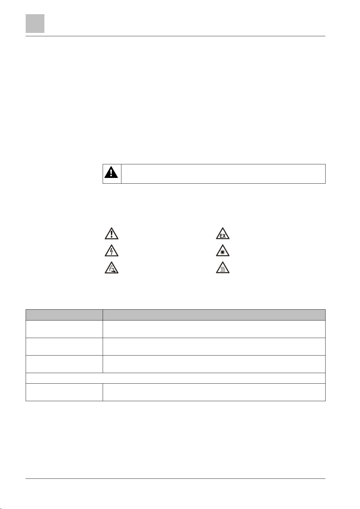
These symbols indicate general dangers, the type of danger or possible
consequences, measures and prohibitions, examples of which are shown in the
following table:
General danger
Explosive atmosphere
Voltage/electric shock
Battery
Laser light
Heat
Signal word
Symbol for danger
DANGER identifies a dangerous situation, which
The signal word classifies the danger as defined in the following table:
if you do not avoid this situation.
WARNING identifies a dangerous situation, which
CAUTION identifies a dangerous situation, which could result in
NOTICE
| 64
if you do not avoid this situation.
if you do not avoid this situation.
NOTICE
identifies possible damage to property that may result from non-
observance.
2015-05-04
Page 11
1BSafety
12BSafety instructions
2
64
Building Technologies
A6V10212047_m_en_--
Fire Safety
WARNING
Nature and origin of the danger
● Measures / prohibitions for danger avoidance
NOTICE
Nature and origin of the danger
● Measures / prohibitions for danger avoidance
How risk of injury is presented
Information about the risk of injury is shown as follows:
Consequences if the danger occurs
How possible damage to property is presented
Information about possible damage to property is shown as follows:
Consequences if the danger occurs
11 |
2015-05-04
Page 12
1BSafety
13BSafety regulations for the method of operation
2
12
Building Technologies A6V10212047_m_en_--
Fire Safety
WARNING
Electrical voltage
regulations.
2.2 Safety regulations for the method of operation
National standards, regulations and legislation
Siemens products are developed and produced in compliance with the relevant
European and international safety standards. Should additional national or local
safety standards or legislation concerning the planning, mounting, installation,
operation or disposal of the product apply at the place of operation, then these
must also be taken into account together with the safety regulations in the product
documentation.
Electrical installations
Electric shock
● Work on electrical installations may only be carried out by qualified
electricians or by instructed persons working under the guidance and
supervision of a qualified electrician, in accordance with the electrotechnical
● Wherever possible disconnect products from the power supply when carrying
out commissioning, maintenance or repair work on them.
● Lock volt-free areas to prevent them being switched back on again by mistake.
● Label the connection terminals with external external voltage using a
'DANGER External voltage' sign.
● Route mains connections to products separately and fuse them with their own,
clearly marked fuse.
● Fit an easily accessible disconnecting device in accordance with IEC 60950-1
outside the installation.
● Produce earthing as stated in local safety regulations.
Mounting, installation, commissioning and maintenance
● If you require tools such as a ladder, these must be safe and must be intended
for the work in hand.
● When starting the fire control panel ensure that unstable conditions cannot
arise.
● Ensure that all points listed in the 'Testing the product operability' section below
are observed.
● You may only set controls to normal function when the product operability has
been completely tested and the system has been handed over to the customer.
| 64
2015-05-04
Page 13

1BSafety
13BSafety regulations for the method of operation
2
64
Building Technologies
A6V10212047_m_en_--
Fire Safety
Testing the product operability
● Prevent the remote transmission from triggering erroneously.
● If testing building installations or activating devices from third-party companies,
you must collaborate with the people appointed.
● The activation of fire control installations for test purposes must not cause
injury to anyone or damage to the building installations. The following
instructions must be observed:
– Use the correct potential for activation; this is generally the potential of the
building installation.
– Only check controls up to the interface (relay with blocking option).
– Make sure that only the controls to be tested are activated.
● Inform people before testing the alarm devices and allow for possible panic
responses.
● Inform people about any noise or mist which may be produced.
● Before testing the remote transmission, inform the corresponding alarm and
fault signal receiving stations.
Modifications to the system design and the products
Modifications to the system and to individual products may lead to faults,
malfunctioning and safety risks. Written confirmation must be obtained from
Siemens and the corresponding safety bodies for modifications or additions.
Modules and spare parts
● Components and spare parts must comply with the technical specifications
defined by Siemens. Only use products specified or recommended by
Siemens.
● Only use fuses with the specified fuse characteristics.
● Wrong battery types and improper battery changing lead to a risk of explosion.
Only use the same battery type or an equivalent battery type recommended by
Siemens.
● Batteries must be disposed of in an environmentally friendly manner. Observe
national guidelines and regulations.
Disregard of the safety regulations
Before they are delivered, Siemens products are tested to ensure they function
correctly when used properly. Siemens disclaims all liability for damage or injuries
caused by the incorrect application of the instructions or the disregard of danger
warnings contained in the documentation. This applies in particular to the following
damage:
● Personal injuries or damage to property caused by improper use and incorrect
application
● Personal injuries or damage to property caused by disregarding safety
instructions in the documentation or on the product
● Personal injury or damage to property caused by poor maintenance or lack of
maintenance
13 |
2015-05-04
Page 14
1BSafety
14BStandards and directives complied with
2
14
Building Technologies A6V10212047_m_en_--
Fire Safety
WARNING
Limited or non-existent fire detection
detection installation.
NOTICE
Incorrect planning and/or configuration
detection installation.
2.3 Standards and directives complied with
A list of the standards and directives complied with is available from your Siemens
contact.
2.4 Release Notes
Limitations to the configuration or use of devices in a fire detection installation with
a particular firmware version are possible.
Personal injury and damage to property in the event of a fire.
● Read the 'Release Notes' before you plan and/or configure a fire detection
installation.
● Read the 'Release Notes' before you carry out a firmware update to a fire
Important standards and specifications are not satisfied.
Fire detection installation is not accepted for commissioning.
Additional expense resulting from necessary new planning and/or configuration.
● Read the 'Release Notes' before you plan and/or configure a fire detection
installation.
● Read the 'Release Notes' before you carry out a firmware update to a fire
| 64
2015-05-04
Page 15
2BStructure and function
16BOverview
3
64
Building Technologies
A6V10212047_m_en_--
Fire Safety
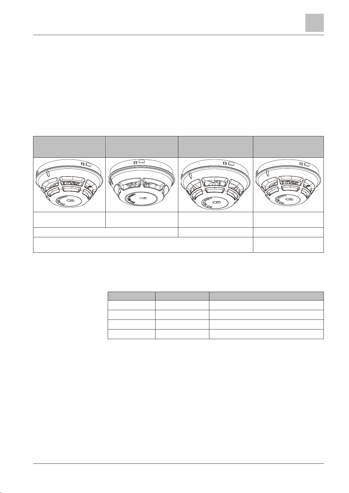
Multi-sensor smoke detector
OH720
Smoke detector
OP720
Heat detector (static and
differential)
HI720
Heat detector (static only)
HI722
Type
Order no.
Designation
3 Structure and function
3.1 Overview
In this document the following point detectors are referred to collectively using the
term 'Automatic fire detectors':
● Multi-sensor smoke detector OH720
● Smoke detector OP720
● Heat detector (static and differential) HI720
● Heat detector (static only) HI722
Can be used addressed on the
C-NET
2 parameter sets 2 parameter sets 1 parameter set
Detection behavior can be selected Detection behavior cannot be
Can be used addressed on the
C-NET
Can be used addressed on the CNET
Can be used addressed on the
C-NET
selected
3.1.1 Details for ordering
OH720 S54310-F2-A1 Multi-sensor smoke detector
OP720 S54310-F1-A1 Smoke detector
HI720 S54310-F4-A1 Heat detector (static and differential)
HI722 S54310-F3-A1 Heat detector (static only)
15 |
2015-05-04
Page 16
2BStructure and function
16BOverview
3
16
Building Technologies A6V10212047_m_en_--
Fire Safety
Depending on the product and various approvals, the product labels may differ in
ES
ES
04
3.1.2 Product version ES
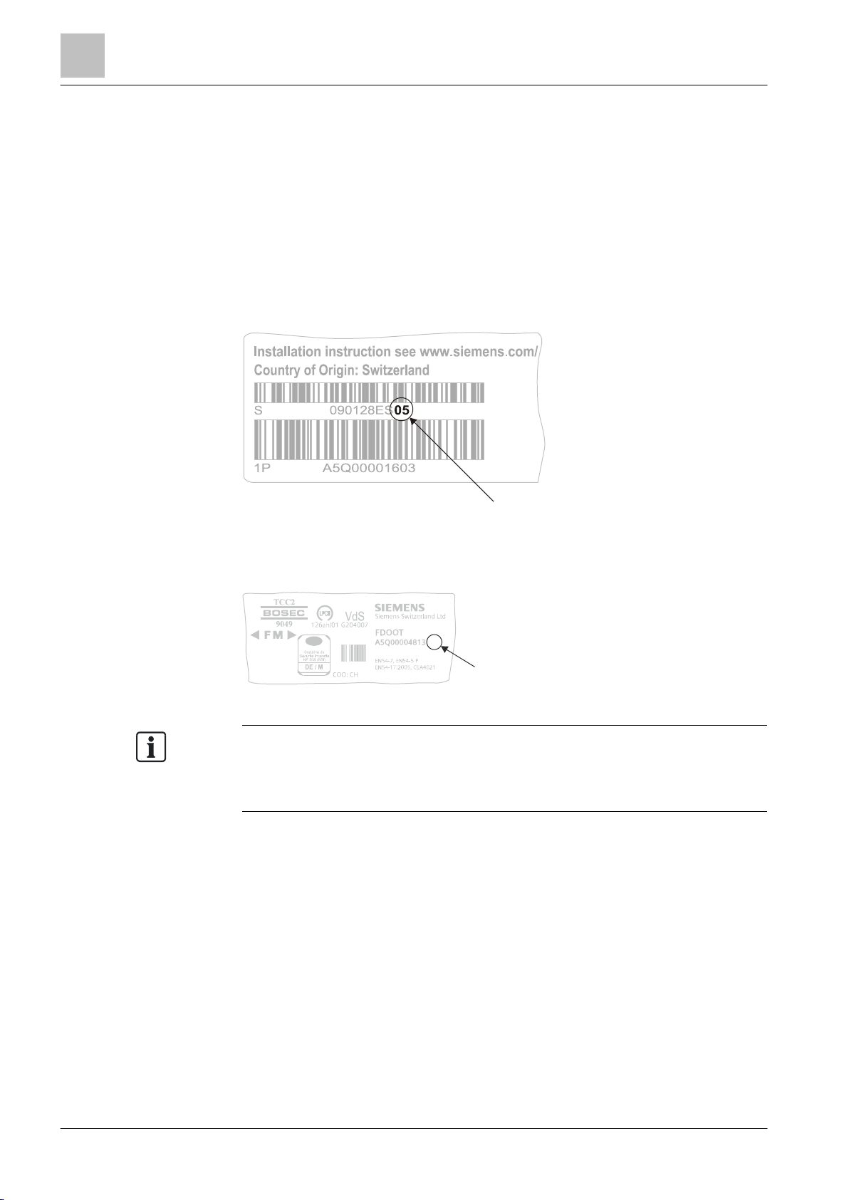
The product version ES provides the technical status of a device in terms of
software and hardware. The product version is provided as a two-digit number.
You will find the details of your device's product version:
● On the packaging label
● On the product label or the type plate
Product version on the packaging label
Details of the product version can be found directly on the packaging label in the
barcode:
Figure 1: Example of a packaging label with details of the product version
Product version on the product label and the type plate
Details of the product version can be found after the device order number:
Figure 2: Example of a product label with details of the product version
terms of the information type and layout.
Look for your device's order number on the product label.
You will find the product version after the order number.
| 64
2015-05-04
Page 17
2BStructure and function
17BPoint detector
3
64
Building Technologies
A6V10212047_m_en_--
Fire Safety
1
2
3
4
3.2 Point detector
3.2.1 Multi-sensor smoke detector
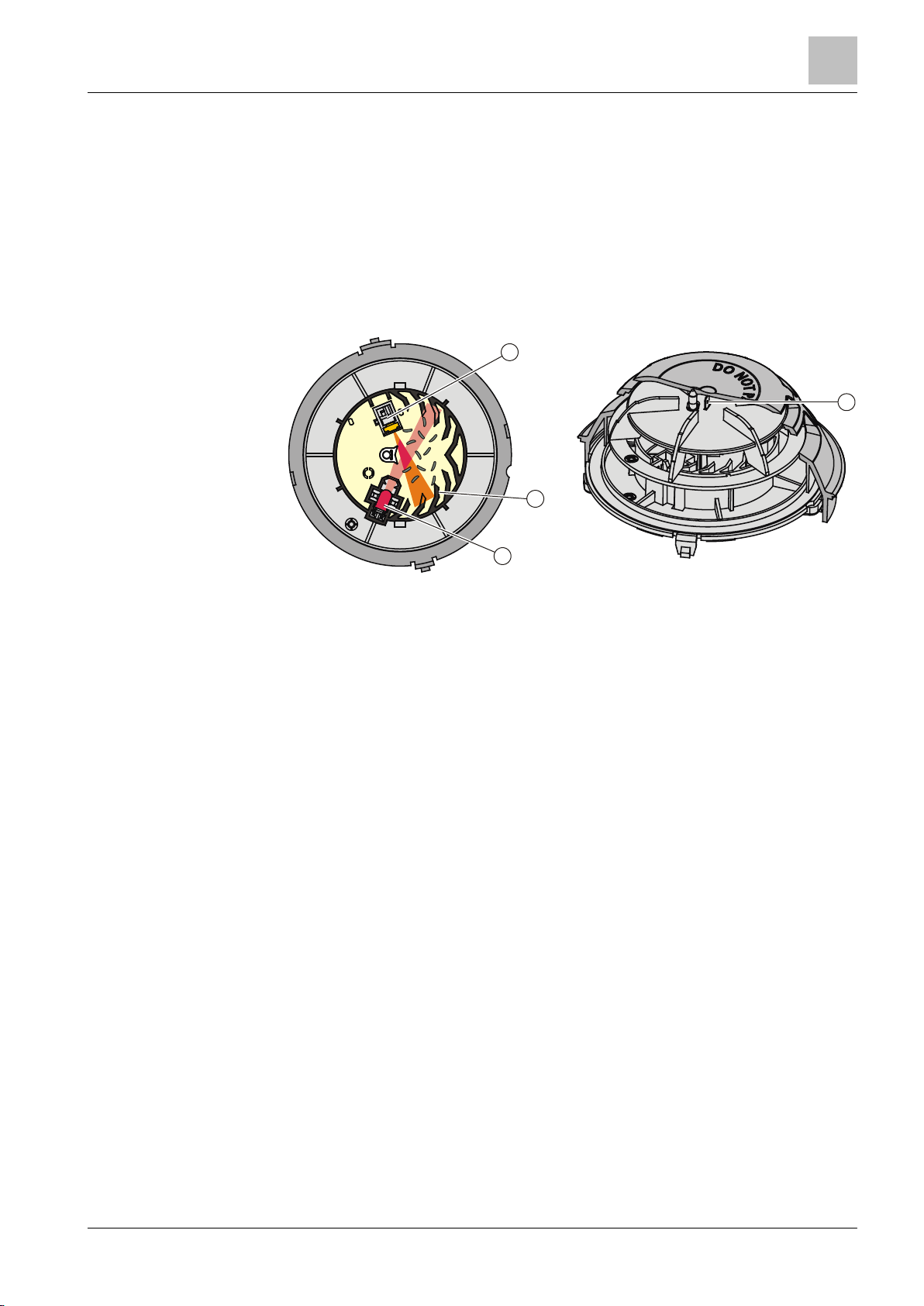
The multi-sensor smoke detector OH720 is a multiple criteria fire detector with one
optical and one thermal sensor.
Structure and function
1 Labyrinth 3 Optical receiver
2 Optical transmitter 4 Heat sensor
The detector has a high-quality opto-electronic measuring chamber. The
measuring chamber contains:
● One optical transmitter
● One optical receiver
● One thermal sensor
The transmitter lights up the smoke particles. The scattered light then hits the
receiver (photodiode) and generates a measurable electric signal.
In addition, the heat sensor makes it possible to detect fires in cases where no
smoke has been generated.
The combination of optical and thermal sensor signals optimizes detection
reliability with the following benefits.
● Early detection of all types of fire, whether they generate light or dark smoke, or
no smoke at all.
● The fire detector can be operated at a lower sensitivity level, thus achieving
improved immunity against false alarms which may be caused by cold
aerosols. In the event of an open fire, the smoke sensitivity level is raised by an
increase in temperature which makes rapidly burning fires easier to detect.
The multi-sensor smoke detector OH720 has two parameter sets: 'Robust' and
'Sensitive'.
The multi-sensor smoke detector is addressed by the control panel when first
switched on.
If a short-circuit occurs, the defective part on the detector line is located by the
control panel and isolated between two detectors. In addition, a loop line
installation ensures an optimum level of safety.
See also
Multi-sensor smoke detector [➙ 31]
17 |
2015-05-04
Page 18
2BStructure and function
17BPoint detector
3
18
Building Technologies A6V10212047_m_en_--
Fire Safety
1
2
3
3.2.2 Smoke detector
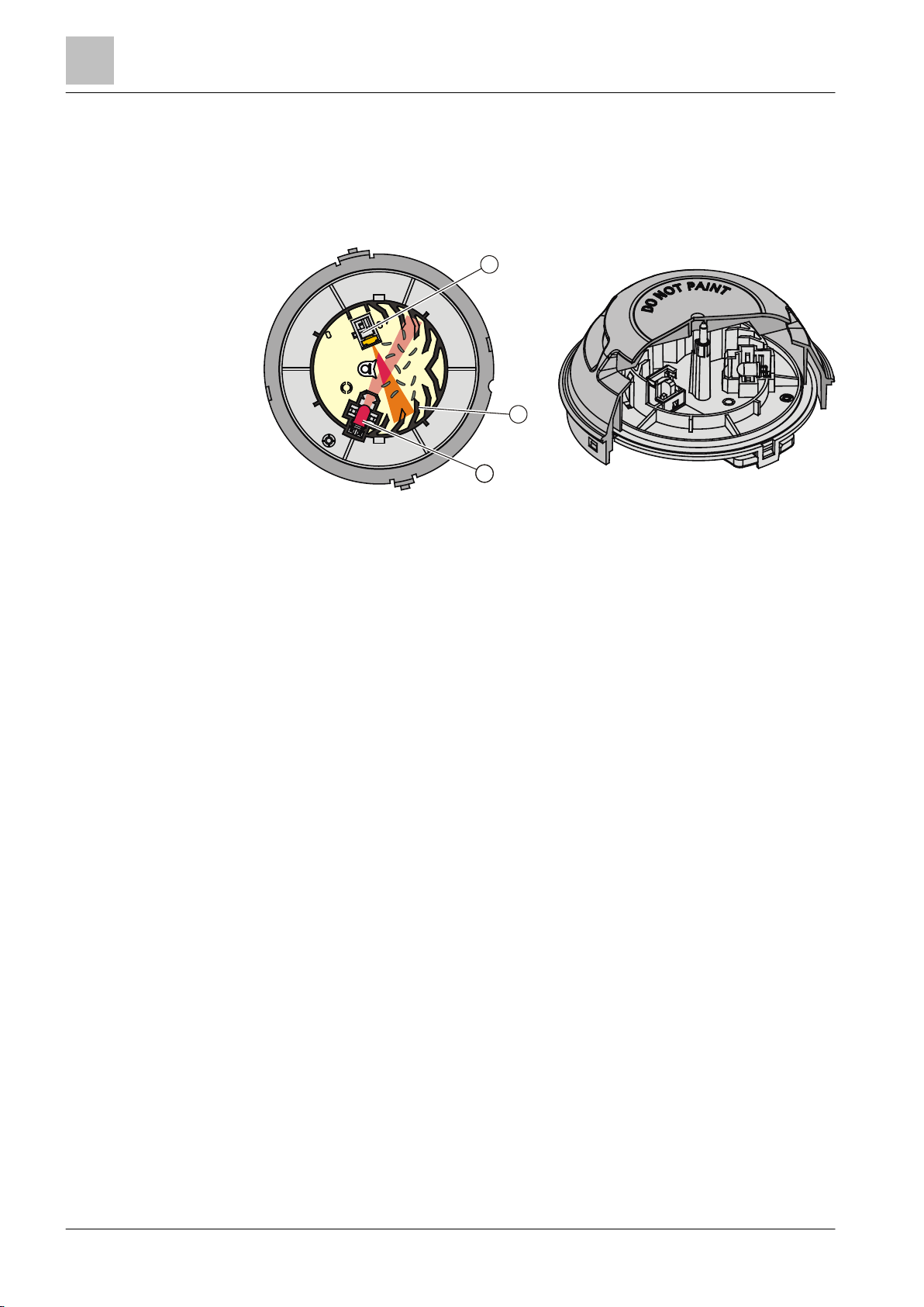
The wide-spectrum smoke detector OP720 is an optical smoke detector with an
optical sensor.
Structure and function
1 Labyrinth 3 Optical receiver
2 Optical transmitter
The wide-spectrum smoke detector has the same measuring chamber as the multisensor smoke detector.
The smoke detector OP720 addresses itself automatically when the control panel
is first switched on, thus enabling individual identification in the event of an alarm.
If a short-circuit occurs, the defective part on the detector line is located by the
control panel and isolated between two detectors. In addition, a loop line
installation ensures an optimum level of safety.
The smoke detector OP720 has two parameter sets: 'Standard' and 'Sensitive'.
See also
Smoke detector [➙ 32]
| 64
2015-05-04
Page 19
2BStructure and function
17BPoint detector
3
64
Building Technologies
A6V10212047_m_en_--
Fire Safety
HI720
HI722
1
3.2.3 Heat detector
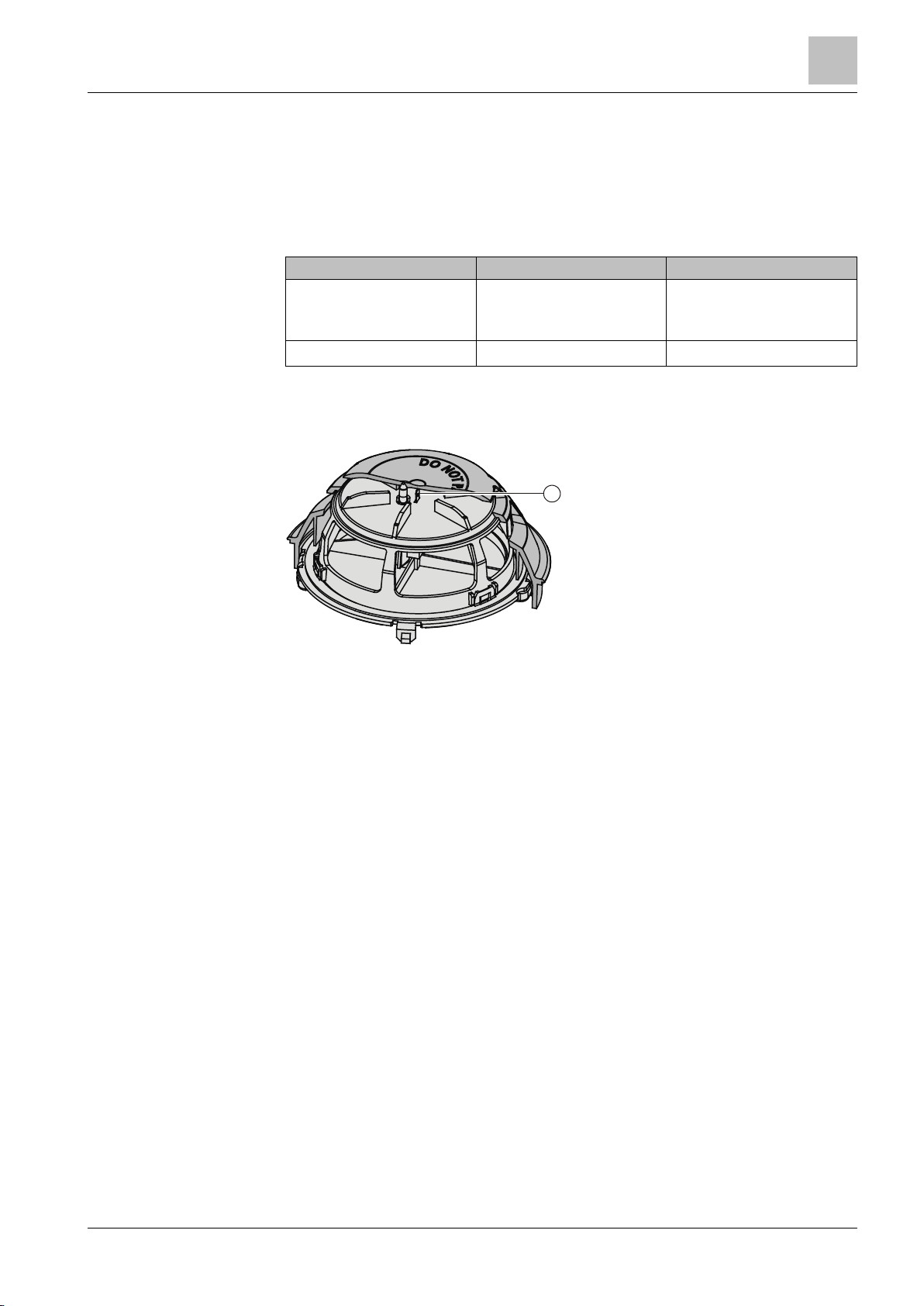
The heat detectors HI720 and HI722 have a straightforward design featuring a
thermal sensor.
The following table indicates the most important differences between the two heat
detectors.
Alarm activation by: ● Temperature increase
● Reaching the maximum
temperature
Number of parameter sets 2 1
● Reaching the maximum
temperature
Structure and function
1 Heat sensor
The heat detector HI720 has two parameter sets: 'A2S' (static) and 'A2R'
(differential).
The heat detector HI722 has one parameter set: 'A2S' (static).
The heat detectors HI720 and HI722 address themselves automatically when the
control panel is first switched on, thus enabling individual identification in the event
of an alarm.
If a short-circuit occurs, the defective part on the detector line is located by the
control panel and isolated between two detectors. In addition, a loop line
installation ensures an optimum level of safety.
See also
Heat detector [➙ 33]
19 |
2015-05-04
Page 20
2BStructure and function
18BFunction
3
20
Building Technologies A6V10212047_m_en_--
Fire Safety
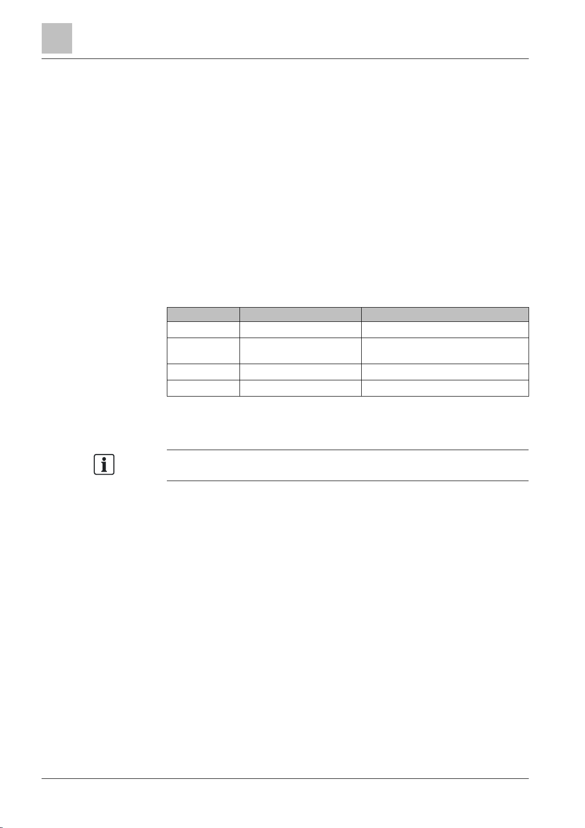
Danger level
Meaning
Comment
The evaluation of the danger level and the decisions to be taken (e.g. activation of
3.3 Function
3.3.1 Parameter sets
The detection behavior of the detectors is influenced by the parameter sets, so that
it can be specifically adjusted to the fire phenomena and environmental conditions
to be expected in the environment to be monitored.
All parameter sets are programmed in the detectors. During commissioning, the
optimum parameter set must be selected for the conditions at the place of
installation. On a C-NET detector line, this is carried out at the control panel.
3.3.2 Danger levels
Measured values above a "response threshold" are not the only basis for reaching
a danger level. The smoke density progression is also observed over a longer
period of time and evaluated using algorithms.
Fire detectors can transmit the following danger levels to the control panel:
0 No danger Normal condition
1 Check situation A different parameter set should potentially be
2 Warning Possible danger
3 Alarm Fire
selected (inappropriate application)
Each fire detector has danger levels 0…3.
remote transmission) are configured in the relevant control panel.
3.3.3 Diagnosis levels
The point detector monitors most of its functions itself. In particular it monitors the
correct functioning of the microcontroller, temperature sensors, light emitter and
light receiver.
The following diagnosis levels are derived from the different control measurements:
● Normal
● Observe information
● Replacement recommended
● Replacement necessary
● Fault
When a fatal error occurs, which prevents the proper function of the detector, a
fault message is signaled.
| 64
2015-05-04
Page 21
2BStructure and function
18BFunction
3
64
Building Technologies
A6V10212047_m_en_--
Fire Safety
Operating condition
Flashing mode of the IAI
The flashing behavior of the point detectors in the case of ES ≥10 is described in
Information about the product version of your device can be found in the 'Product
3.3.4 Line separator
All C-NET devices are equipped with a line separator.
The C-NET device is equipped with electronic switches which isolate the defective
part in case of a short-circuit on the C-NET detector line. The rest of the detector
line remains serviceable. On a loop line all C-NET devices remain fully functional
after a simple error.
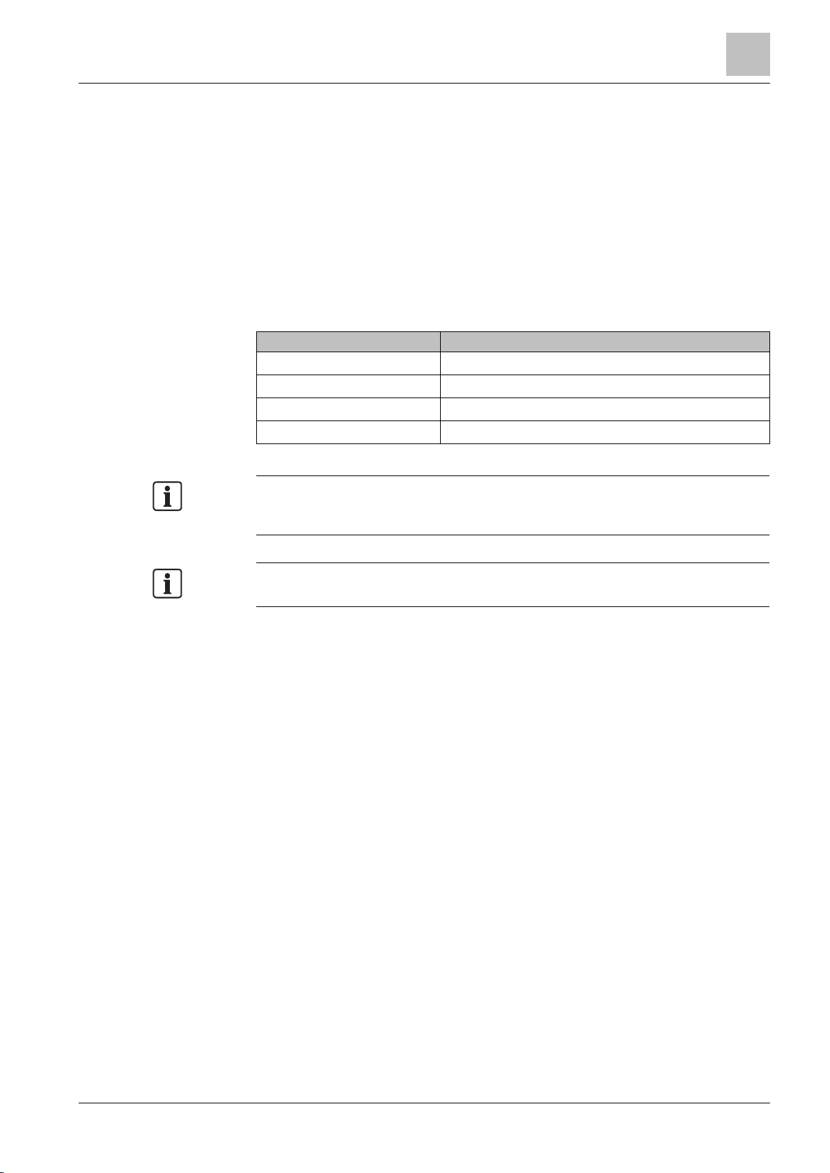
3.3.5 Internal alarm indicator in the case of ES <10
The point detectors have an internal alarm indicator. The internal alarm indicator
shows the point detector's operating status:
Normal IAI off
Alarm IAI lights up every second
Test mode IAI off
Alarm in test mode IAI lights up every second
the 'Extended flashing behavior of alarm indicators in the case of ES ≥10 [➙ 22]'
chapter.
version ES [➙ 16]' chapter.
21 |
2015-05-04
Page 22
2BStructure and function
18BFunction
3
22
Building Technologies A6V10212047_m_en_--
Fire Safety
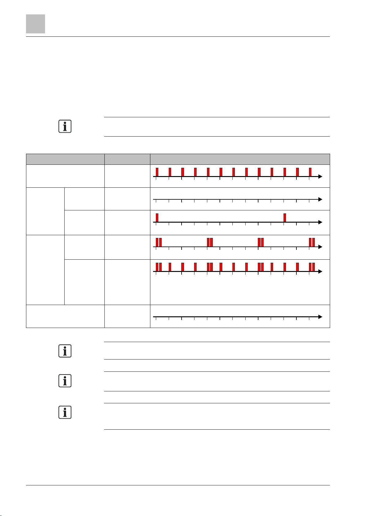
Several flashing patterns are available for normal operation. The flashing pattern
Operating condition
Flashing mode
Graphic
Not all fire control panels support the flashing patterns described.
A steady-on flashing mode for the alarm and an alternative flashing mode for
The above graphics are not valid in countries in which the alarm is indicated by an
t
0 1 2 3 4 5 6 7 8 9 10 1211
[s]
t
0 1 2 3 4 5 6 7 8 9 10 1211
[s]
t
0 1 2 3 4 5 6 7 8 9 10 1211
[s]
t
0 1 2 3 4 5 6 7 8 9 10 1211
[s]
t
0 1 2 3 4 5 6 7 8 9 10 12
11
[s]
t
0 1 2 3 4 5 6 7 8 9 10 1211
[s]
3.3.6 Extended flashing behavior of alarm indicators in the case of ES ≥10
Internal alarm indicators
The table below describes the flashing behavior of internal alarm indicators in the
case of an ES ≥10:
is selected using the 'Cerberus-Engineering-Tool' software.
Alarm IAI flashes red
once a second
Normal Configuration
1 (
default
IAI off
)
Configuration 2 IAI flashes red
every
10 seconds
Test mode Normal IAI flashes red
twice every
4 seconds
Alarm IAI flashes red
twice every
4 seconds and
red every
second inbetween
Fault IAI off
normal operation can be set using the 'Cerberus-Engineering-Tool' software.
alarm indicator that lights up permanently. For more information, please contact
your regional company.
Please also observe the documentation for your fire detection system.
| 64
2015-05-04
Page 23
2BStructure and function
18BFunction
3
64
Building Technologies
A6V10212047_m_en_--
Fire Safety
Operating condition
Flashing mode
Graphic
EAI flashes red
EAI flashes red
Information about the product version of your point detector can be found in the
The flashing behavior of the point detectors in the case of ES ≥10 is described in
Information about the product version of your device can be found in the 'Product
t
0 1 2 3 4 5 6 7 8 9 10 1211
[s]
t
0 1 2 3 4 5 6 7 8
9
10 1211
[s]
t
0 1 2 3 4 5 6 7 8 9 10 1211
[s]
t
0 1 2 3 4 5 6 7 8 9 10 1211
[s]
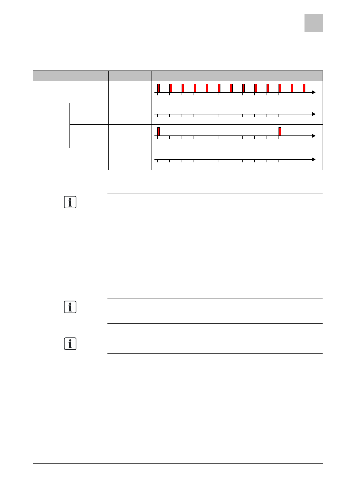
Alarm
External alarm indicators
The table below describes the flashing behavior of external alarm indicators in
combination with a point detector with an ES ≥10:
every second
Normal Configuration
default
1 (
)
EAI off
Configuration
2
every
10 seconds
Fault EAI off
'Product version ES [➙ 16]' chapter.
3.3.7 Connection for external alarm indicators
Two external alarm indicators can be connected to each detector. On the C-NET, it
is possible to connect the external alarm indicator to any detector. The trigger for
activating the alarm indicator can be programmed at the control panel.
See also
Applicable documents [➙ 7]
the 'Extended flashing behavior of alarm indicators in the case of ES ≥10 [➙ 22]'
chapter.
version ES [➙ 16]' chapter.
3.3.8 Test mode
It is possible to set all the detectors to test mode for testing purposes. Optical
detectors can be tested with the test gas REF8 or REF8-S. Heat detectors can be
tested with a hot air fan.
23 |
2015-05-04
Page 24

2BStructure and function
18BFunction
3
24
Building Technologies A6V10212047_m_en_--
Fire Safety
3.3.9 Behavior in degraded mode
Applicable for the C-NET:
When the main processor of the fire control panel fails, the control panel works in
degraded mode operation. Depending on the control panel type, the fire control
panel can continue to perform the most important alarming and signaling functions
in degraded mode operation.
Behavior of control panels that support degraded mode operation:
Alarming is still ensured in degraded mode operation. However, in degraded mode
only collective alarming is possible. This means that in the event of an alarm, it is
possible to identify the C-NET detector line but not the exact location of the
detector triggering the alarm.
When a sounder base DBS720 is connected to the output for the external alarm
indicator, it is activated in degraded mode in the case of a fire alarm.
Degraded mode operation on the C-NET is not supported in the same way by all
control panels. The information in the 'List of compatibility' and in the corresponding
control panel documentation must be taken into account during project planning.
3.3.10 Line tester
The line tester FDUL221 is able to recognize and localize the following errors on
the C-NET:
● Wiring error
● Open line
● Short-circuit
● Ground fault
In addition, the line tester recognizes the devices connected to the C-NET detector
line.
You will find more information in document 008250.
See also
Applicable documents [➙ 7]
| 64
2015-05-04
Page 25
2BStructure and function
19BMechanical setup
3
64
Building Technologies
A6V10212047_m_en_--
Fire Safety
3.4 Mechanical setup
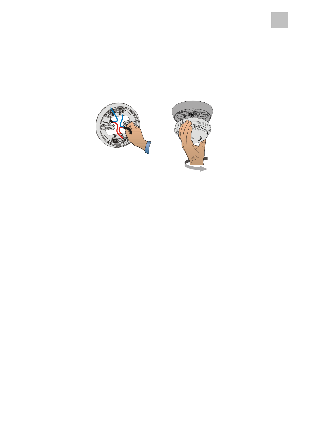
One of the following devices is required to install a point detector:
● Detector base DB72x
● Sounder base DBS720
After installing the detector base or sounder base, simply insert the point detector
in the base and turn it, either manually or using the detector exchanger DX791,
until you hear and feel it snap in.
Properties
● Quick installation and secure contact
● The centered alarm indicator makes an alignment of the detector base
superfluous
● Space for up to 4 auxiliary terminals
Accessories are available for a variety of different applications and can be
combined to suit the particular application in question.
See also
Accessories [➙ 26]
25 |
2015-05-04
Page 26
2BStructure and function
20BAccessories
3
26
Building Technologies A6V10212047_m_en_--
Fire Safety
3.5 Accessories
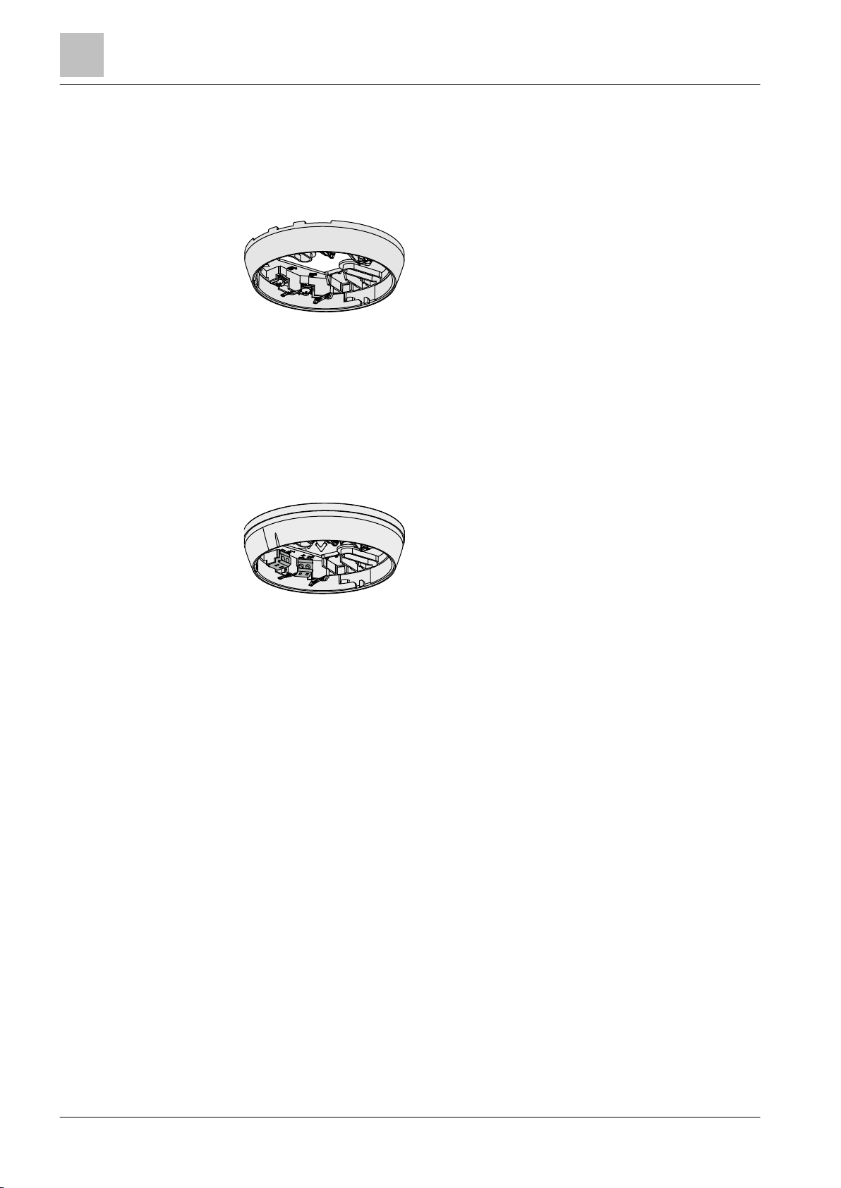
3.5.1 Detector base with loop contact DB721
● For the mounting of point detectors
● Thanks to the loop contacts, the detector line is not
interrupted when there is no point detector installed in the
detector base.
● For the recess-mounted cable entry
● For surface-mounted cable entry, up to 8 mm cable
diameter
● Compatible with:
● Order no.: S54319-F11-A1
See also
Detector base DB72x [➙ 36]
3.5.2 Detector base DB722
● For the mounting of point detectors
● Thanks to the loop contacts, the detector line is not
interrupted when there is no point detector installed in the
detector base.
● For the recess-mounted cable entry
● For surface-mounted cable entry, up to 8 mm cable
diameter
● Seal integrated in the detector base. Protection
category: IP42.
● Cable connection via spring clips
● Compatible with:
– Multi-sensor fire detector OH720
– Smoke detector OP720
– Heat detector HI720
– Heat detector HI722
– Multi-sensor smoke detector, ASA OOH740
– Neural fire detector OOHC740
● Order no.: S54319-F19-A1
See also
Detector base DB72x [➙ 36]
| 64
2015-05-04
Page 27
2BStructure and function
20BAccessories
3
64
Building Technologies
A6V10212047_m_en_--
Fire Safety
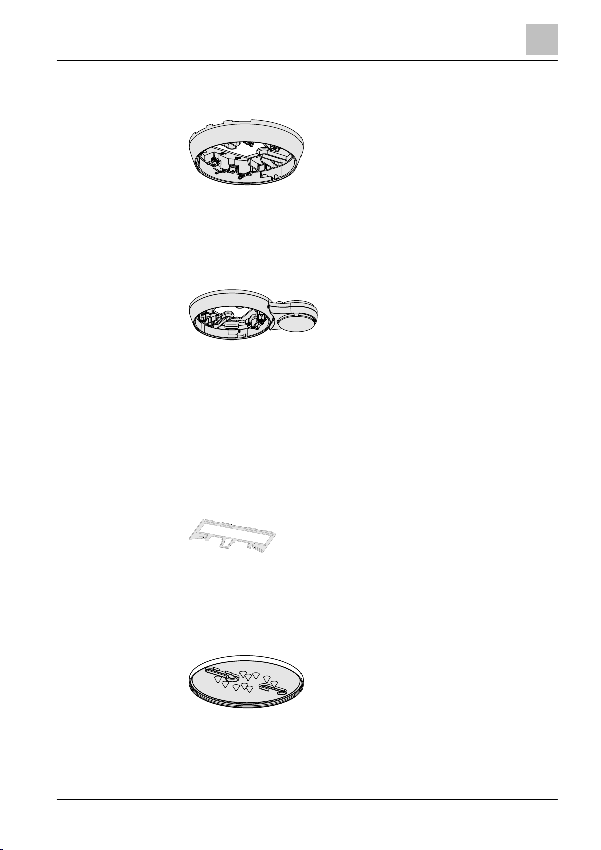
3.5.3 Detector base DB720
● For the installation of point detectors
● For the recess-mounted cable entry
● For surface-mounted cable entry, up to 8 mm cable
diameter
● Compatible with:
● Order no.: S54319-F4-A1
See also
Detector base DB72x [➙ 36]
3.5.4 Sounder base DBS720
● For acoustic alarming in the case of an event
● Thanks to the loop contacts, the detector line is not
interrupted when there is no point detector installed in the
sounder base.
● For the C-NET detector line
● For the recess-mounted cable entry
● For surface-mounted cable entry, up to 8 mm cable
diameter
● Compatible with:
● You will find more information in document A6V10218037
● Order no.: S54319-F5-A1
See also
Sounder base DBS720 [➙ 38]
3.5.5 Designation plate FDBZ291
● To identify the location
● Compatible with:
● Order no. A5Q00002621
See also
Designation plate FDBZ291 [➙ 45]
3.5.6 Detector base seal RS720
● For installation in wet rooms
● Protection category IP42
● Compatible with:
● Order no.: S54319-F8-A1
See also
Detector base seal RS720 [➙ 39]
27 |
2015-05-04
Page 28
2BStructure and function
20BAccessories
3
28
Building Technologies A6V10212047_m_en_--
Fire Safety
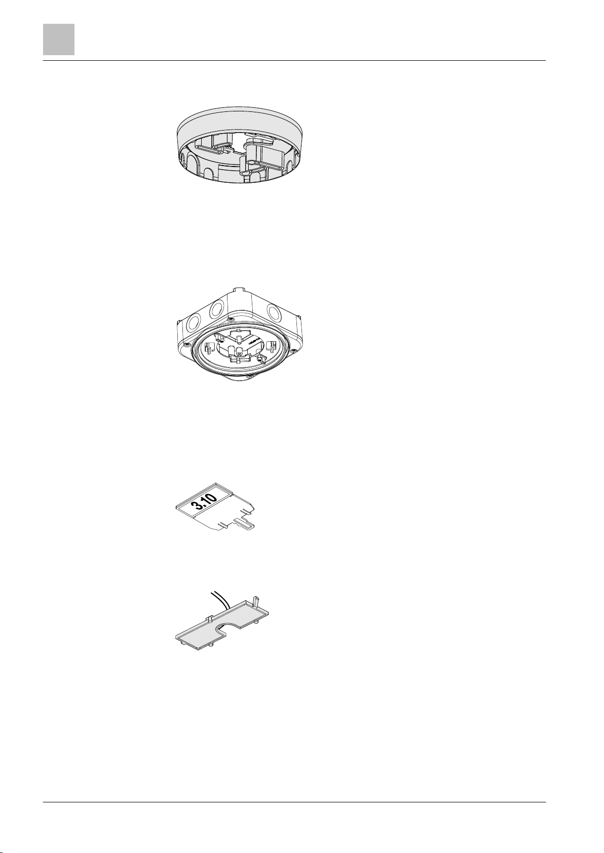
3.5.7 Base attachment BA720
● There are several potential break-out points in the base
attachment for surface-mounted cable entry
● For the recess-mounted cable entry
● Permanent connection and joint installation with detector
base
● Compatible with:
● Order no.: S54319-F20-A1
See also
Base attachment BA720 [➙ 40]
3.5.8 Base attachment wet BA721
● For installation in humid, wet environments and if the
detector heating unit is used
● Protection category achievable: IP44
● Six break-out points for M20 x 1.5 metal cable glands
● Compatible with:
● Order no.: S54319-F29-A1
See also
Base attachment wet BA721 [➙ 41]
3.5.9 Designation plate DBZ1193A
● To identify the location
● Compatible with:
● Order no.: BPZ:4864330001
3.5.10 Detector heating unit FDBH291
● For operating point detectors in critical ambient conditions
during icy conditions or when there is a danger of
moisture condensation
● Compatible with:
● Order no.: A5Q00004439
| 64
See also
Detector heating unit FDBH291 [➙ 50]
Base attachment wet BA721 [➙ 41]
2015-05-04
Page 29
2BStructure and function
20BAccessories
3
64
Building Technologies
A6V10212047_m_en_--
Fire Safety
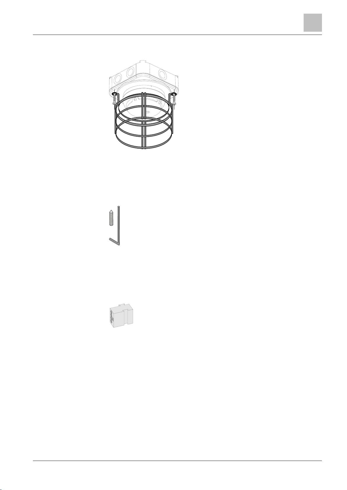
3.5.11 Protective cage DBZ1194
● To protect the devices against mechanical damage
● Can only be used in conjunction with the following
accessories:
● Order no.: BPZ:4677110001
See also
Base attachment wet BA721 [➙ 41]
3.5.12 Detector locking device LP720
● For protection against theft
● Compatible with:
● Order no.: S54319-F9-A1
See also
Detector locking device LP720 [➙ 44]
3.5.13 Micro terminal DBZ1190-AA
● Auxiliary terminal for connecting cables
● For T-branches of additional cabling e.g. for detector
heating units, sounder base, external alarm indicators etc.
● For wire diameters of 0.28…0.5 mm
● 4-pin
● Order no.: BPZ:4677080001
See also
Auxiliary terminals DBZ1190-AA/-AB [➙ 47]
2
29 |
2015-05-04
Page 30

2BStructure and function
20BAccessories
3
30
Building Technologies A6V10212047_m_en_--
Fire Safety
3.5.14 Connection terminal DBZ1190-AB
● Auxiliary terminal for connecting cables
● For T-branches of additional cabling e.g., for cable
shielding, detector heating units, sounder base, external
alarm indicators, etc.
See also
Auxiliary terminals DBZ1190-AA/-AB [➙ 47]
● For wire diameters of 1…2.5 mm²
● 3 poles
● Order no.: BPZ:4942340001
| 64
2015-05-04
Page 31

3BPlanning
21BCompatibility
4
64
Building Technologies
A6V10212047_m_en_--
Fire Safety
Detector line
Control panel
FC20xx
FC72x
SIGMASYS
AlgoRex
FDnet
C-NET
4 Planning
4.1 Compatibility
Compatible with control panels that support the C-NET detector line.
- X – –
– – – –
X = compatible
– = not compatible
You will find detailed information in the 'List of compatibility'.
See also
Applicable documents [➙ 7]
4.2 Multi-sensor smoke detector
Like all optical smoke detectors, the multi-sensor smoke detector OH720 is able to
detect slow-burning fires that generate smoke.
However, when compared to standard optical smoke detectors, the multi-sensor
smoke detector OH720 also offers improved response behavior in the event of
open fires and increased resistance to misleading sources of false alarms.
Multi-sensor smoke detector OH720 has two parameter sets available for
selection.
4.2.1 Parameter sets
(Parameter set numbers and comments in brackets)
Robust (1/Default):
The parameter set 'Robust' offers improved resistance to false alarms in areas
where misleading sources, such as cigarette smoke or exhaust fumes, may cause
these to be triggered.
Sensitive (2):
This parameter set is particularly suitable for areas where few misleading sources
of false alarms are present, and where priority is given to detecting open fires as
early as possible.
The procedure for setting the parameter set via the control panel is described in
the control panel documentation.
31 |
2015-05-04
Page 32

3BPlanning
23BSmoke detector
4
32
Building Technologies A6V10212047_m_en_--
Fire Safety
No.
Name
Thermal
Typ. response
time
Sensitivity
Static activation
temperature
Differential activation
temperature 1
Differential activation
possible from:
[s]
[%/m]
[°C]
∆T [K]
[°C]
All parameter sets meet the criteria of standard EN 54-7.
4.2.2 Specifications
The following table shows the properties of the parameter sets for the multi-sensor
1 Robust 35 3.5 60 25 2 10
2 Sensitive 10 2.5 60 25 2 10
smoke detector OH720:
1
Applicable with fast temperature increases > 10 K/min.
2
Between 1 K/min and 10 K/min, this value increases by a few degrees.
4.3 Smoke detector
The optical smoke detector OP720 demonstrates quick response behavior in the
event of slow-burning fires that generate smoke. It is extremely well suited to
general-purpose applications.
The optical smoke detector OP720 has two parameter sets available for selection.
4.3.1 Parameter sets
(Parameter set numbers and comments in brackets)
Standard (1/Default):
For standard applications, such as in corridors, bedrooms, offices, and living
rooms.
Sensitive (2):
For areas with few misleading sources of false alarms, such as cigarette smoke,
exhaust fumes, and steam.
The procedure for setting the parameter set via the control panel is described in
the control panel documentation.
| 64
2015-05-04
Page 33

3BPlanning
24BHeat detector
4
64
Building Technologies
A6V10212047_m_en_--
Fire Safety
No.
Name
Response time [s]
Sensitivity [%/m]
All parameter sets meet the criteria of standard EN 54-7.
4.3.2 Specifications
The following table shows the properties of the parameter sets for the smoke
detector OP720:
1 Standard 10 2.5
2 Sensitive 10 1.8
4.4 Heat detector
The heat detectors HI720 and HI722 respond when the temperature exceeds a
preset threshold value.
Heat detectors are used in environments where misleading sources of false alarms
are present and where, if smoke detectors were to be used, an unacceptable
number of false alarms would be triggered.
If parameterized appropriately, the heat detector HI720 can recognize sharp
increases in temperature and is suitable for areas with a stable ambient
temperature.
4.4.1 Parameter sets
The heat detectors HI720 and HI722 have the following parameter sets (parameter
set number and comments in brackets):
● A2S (1/Default)
● A2R (2, HI720 only)
Explanation of designation 'A'
● 'A' parameter sets should be applied at an ambient temperature of
approximately 25℃. However, they can be applied at temperatures up to 50
°C. The static response temperature is 60℃.
Explanation of designations 'R' and 'S'
● In comparison to the S-parameter sets, R-parameter sets also trigger alarms in
the event of a temperature increase (e.g., from 20°C to 50°C within a few
minutes).
Explanation of designation '2'
A number '2' appearing between letters denotes the room height according to the
EN 54-5 standard:
● 2 = room height max. 6 m
The procedure for setting the parameter set via the control panel is described in
the control panel documentation.
33 |
2015-05-04
Page 34

3BPlanning
24BHeat detector
4
34
Building Technologies A6V10212047_m_en_--
Fire Safety
No.
Name
Operating temperature
typ. / max.
Static activation
temperature 1
Differential activation
temperature 2
Differential activation
possible from:
[°C]
[°C]
∆T [K]
[°C]
All parameter sets meet the criteria of standard EN 54-5.
4.4.2 Specifications
The following table shows the properties of the parameter sets for the heat
detectors HI720 and HI722:
1 A2S
60 °C maximum
2 A2R
60 °C rate of rise
25 / 50 60 – –
25 / 50 60 25 3 10
1
Applicable with slow temperature increases <1 K/min.
2
Applicable with fast temperature increases > 10 K/min.
3
Between 1 K/min and 10 K/min, this value increases by a few degrees.
| 64
2015-05-04
Page 35
4BMounting / Installation
25BRequired space
5
64
Building Technologies
A6V10212047_m_en_--
Fire Safety
* = min. 2 cm
*
*
*
1
2
5 Mounting / Installation
5.1 Required space
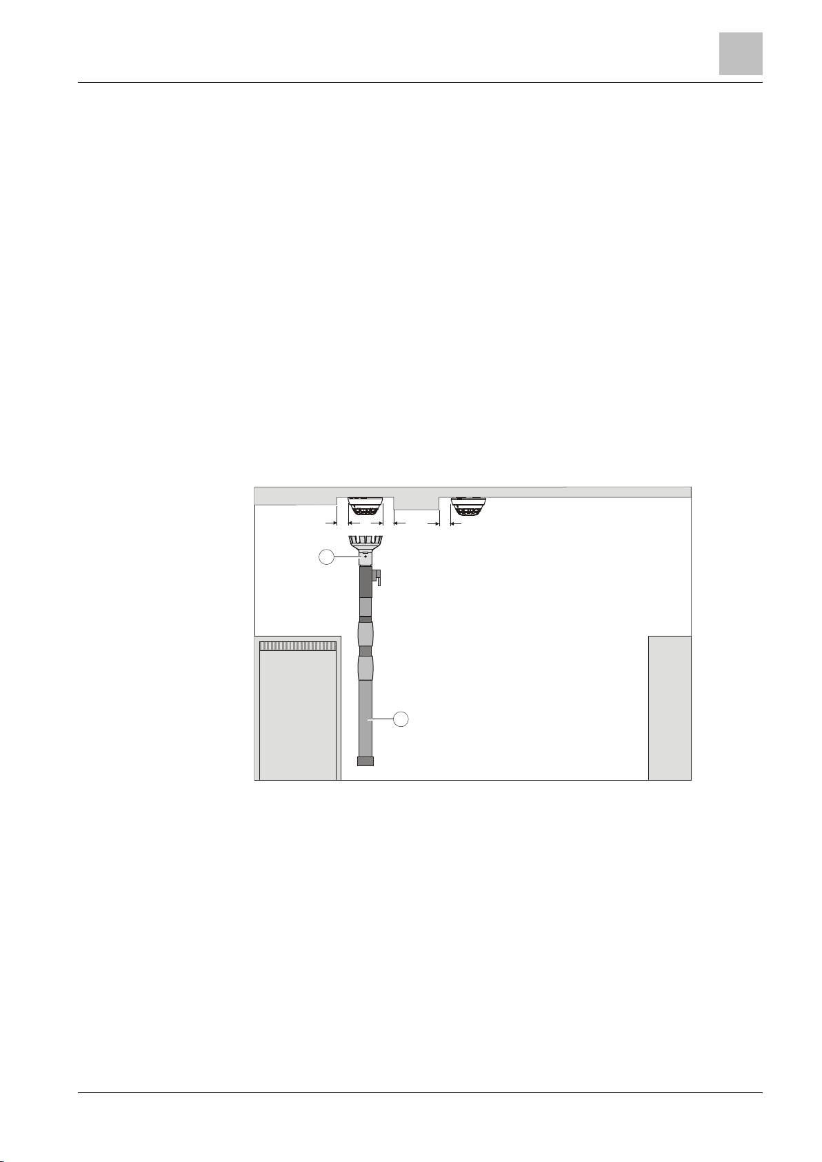
● Upon insertion of the detector base and sounder base, the detector base is
placed under stress by compression, tension, and torsion. The fastening
method must, therefore, be designed accordingly.
● Detector bases and sounder bases must be placed flat on the ceiling.
● Avoid mounting on steps, concrete ribs, etc.
● Install the detector base or sounder base directly on the recessed box or a
level surface.
● If a surface-mounted cable feed is used, there are two possible break-out
points on the detector base or sounder base for the cable entry. Max. cable
diameter: 8 mm.
● The point detector must have at least 2 cm of free space to the side. Only then
can the point detector be removed with the detector exchanger DX791.
● Contorted detector bases or sounder bases will complicate or even impede the
insertion of detectors.
1 Detector exchanger 2 Telescope or extension rod
35 |
2015-05-04
Page 36
4BMounting / Installation
26BDetector base DB72x
5
36
Building Technologies A6V10212047_m_en_--
Fire Safety
NOTICE
Incorrect laying of cables
● The bare length of the cables is approximately 8…10 mm.
NOTICE
Excessively large holes in detector base seal DB722
● Without using a tool, push the lines through the detector base seal.
In the case of the detector base DB721, the C-NET detector line is not interrupted
1
2
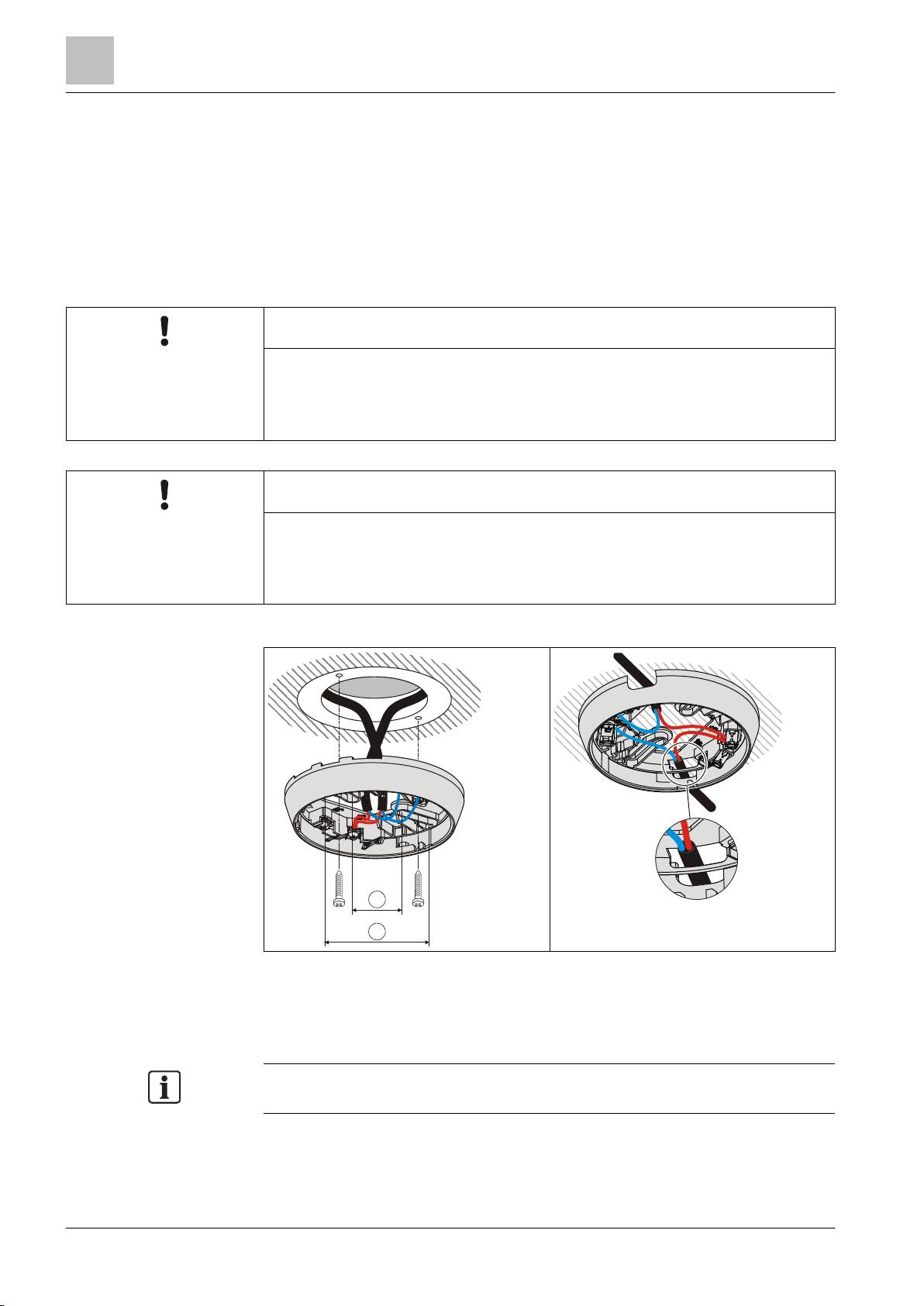
5.2 Detector base DB72x
● Install the detector base DB72x directly on the ceiling.
● Insert the cables into the detector base. You have the option of using the
following types of line:
– Recess-mounted cable entry
– Surface-mounted cable entry (cable diameter max. 8 mm)
Damage to cables and difficulties when installing the point detector
● The cable loops must be placed flat in the base bottom.
Potential IP protection category impaired
● Do not cut or drill holes in the detector base seal.
1 Minimum Ø 40 mm 2 Maximum Ø 90 mm
even if a point detector is not used.
| 64
2015-05-04
Page 37
4BMounting / Installation
26BDetector base DB72x
5
64
Building Technologies
A6V10212047_m_en_--
Fire Safety
DB722
DB721
DB720
Connection terminals
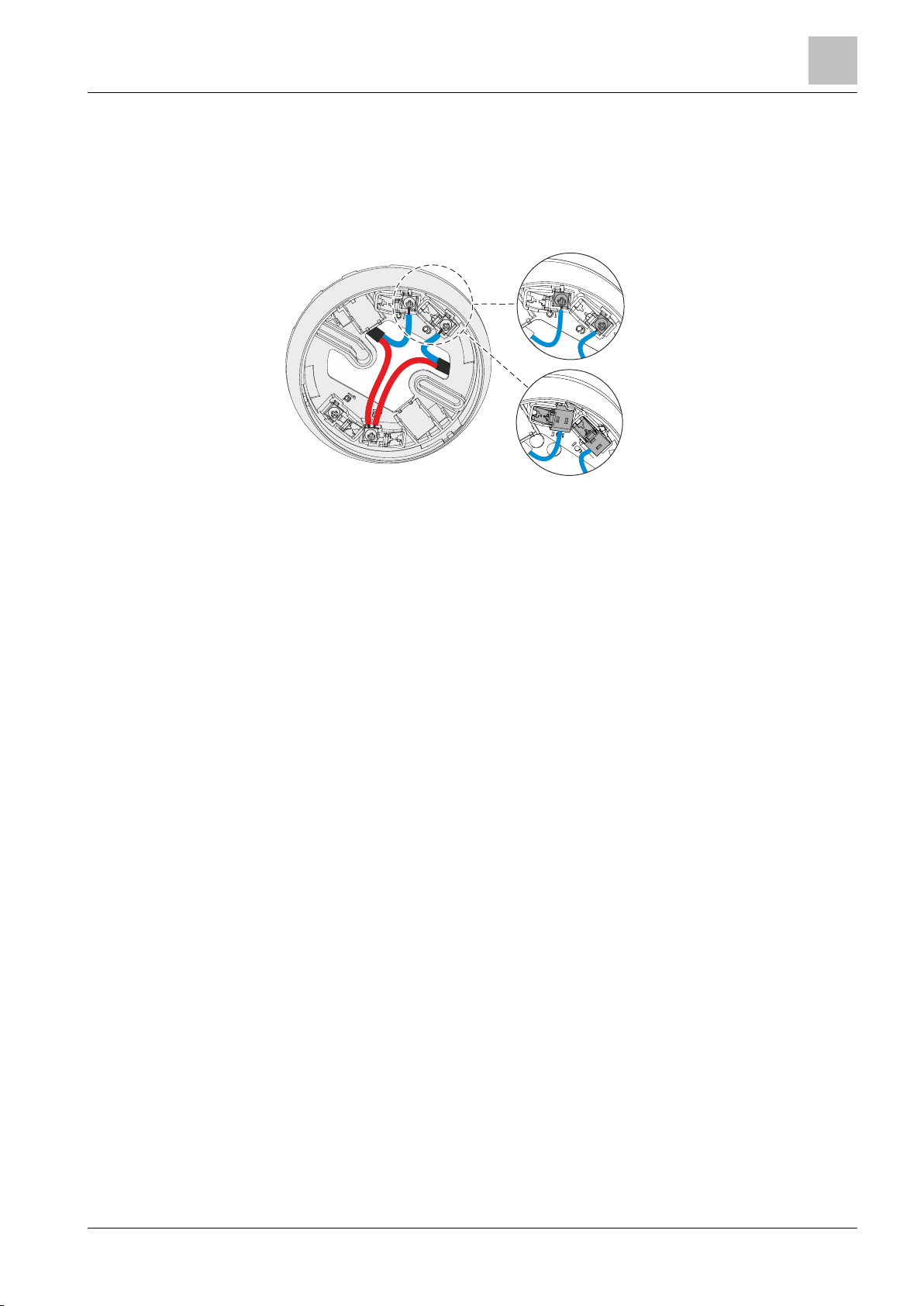
The following detector bases have screw terminals:
● DB721
● DB720
The following detector bases have spring clips:
● DB722
Figure 3: Screw terminals and spring clips
See also
Cable entry [➙ 46]
37 |
2015-05-04
Page 38
4BMounting / Installation
27BSounder base DBS720
5
38
Building Technologies A6V10212047_m_en_--
Fire Safety
NOTICE
Incorrect laying of cables
● The bare length of the cables is approximately 8…10 mm.
In the case of the sounder base DBS720, the C-NET detector line is not
1
2
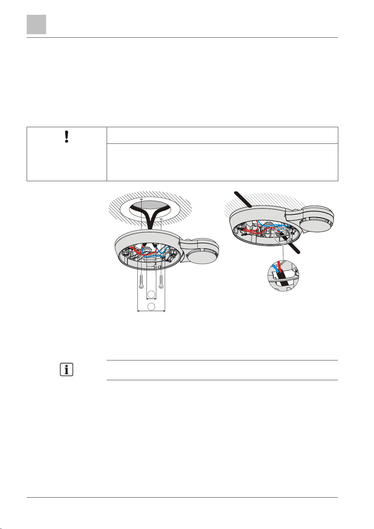
5.3 Sounder base DBS720
1. Install the sounder base DBS720 directly on the ceiling.
2. Insert the cables into the sounder base DBS720. You have the option of using
the following types of line:
– Recess-mounted cable entry
– Surface-mounted cable entry (cable diameter max. 8 mm)
Damage to cables and difficulties when installing the point detector
● The cable loops must be placed flat in the base bottom.
1 Minimum Ø 40 mm 2 Maximum Ø 90 mm
interrupted even if a point detector is not used.
| 64
2015-05-04
Page 39
4BMounting / Installation
28BDetector base seal RS720
5
64
Building Technologies
A6V10212047_m_en_--
Fire Safety
5.4 Detector base seal RS720
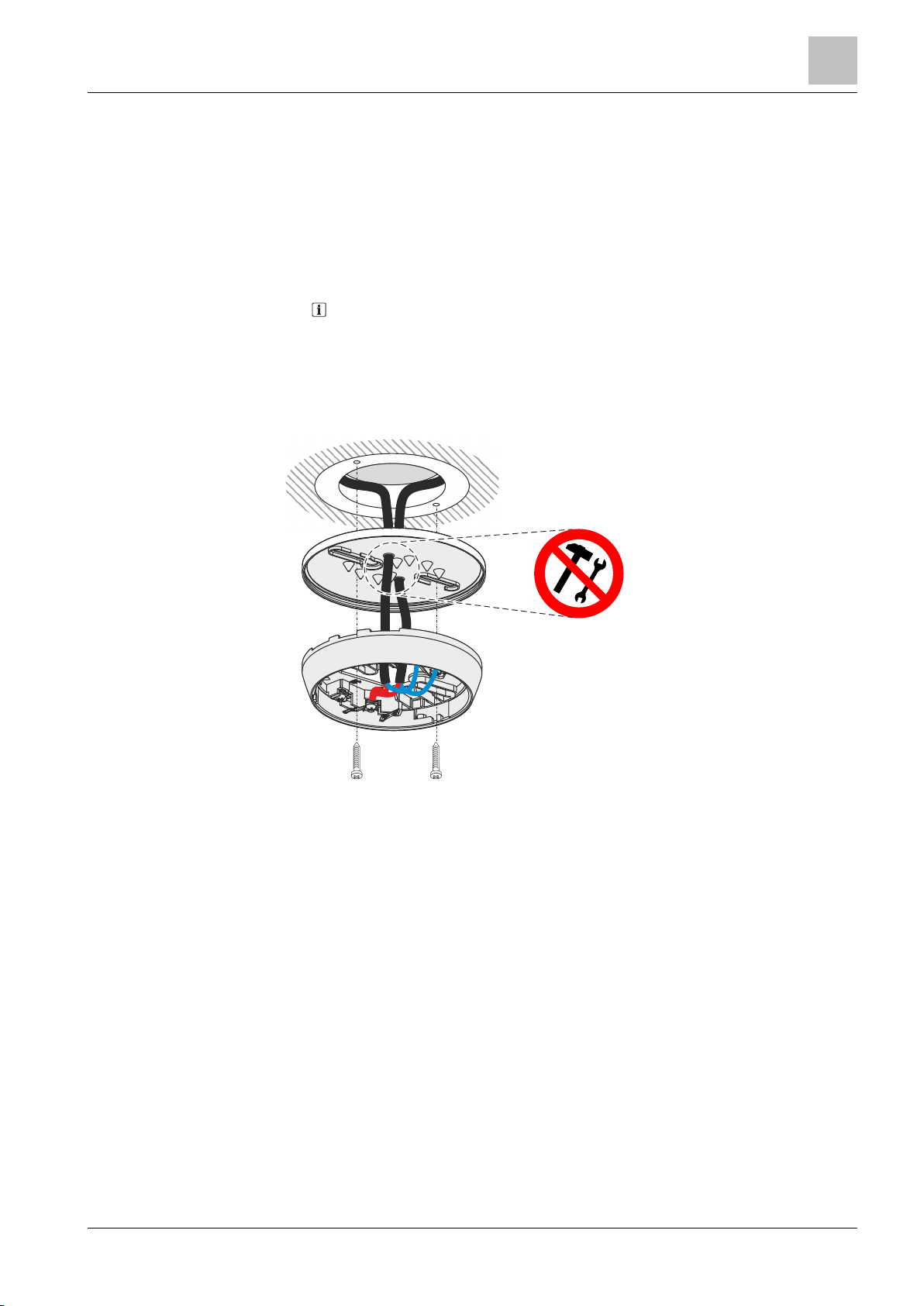
● Use the detector base seal RS720 to install point detectors in wet rooms.
Protection category: IP42.
● Compatible with the detector bases DB72x and the sounder base DBS720.
● Only use for recess-mounted cable entry.
Installing the detector base seal
1. NOTICE! Excessively large holes in the detector base seal will impair the
potential IP protection category. Do not cut or drill holes in the detector base
seal. Without using a tool, push the lines through the detector base seal.
2. Fit the detector base seal RS720 between the ceiling and the detector base
DB72x or the sounder base DB720.
Figure 4: Installing the detector base seal RS720
See also
Detector base seal RS720 [➙ 27]
39 |
2015-05-04
Page 40
4BMounting / Installation
29BBase attachment BA720
5
40
Building Technologies A6V10212047_m_en_--
Fire Safety
1
2
5.5 Base attachment BA720
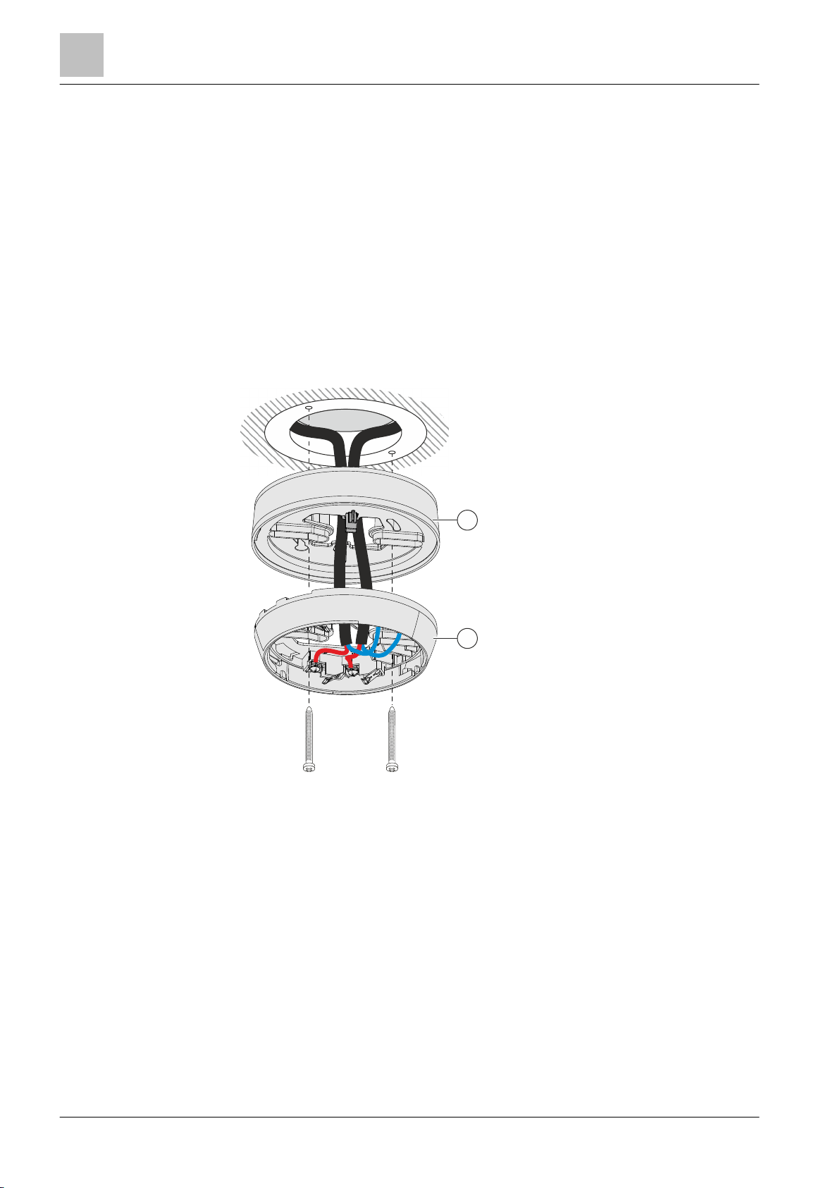
Install base attachment BA720 if you are using a cable with a diameter >8 mm for
surface-mounted cable entry.
The base attachment BA720 is attached to the ceiling together with a detector
base.
Compatible with the detector bases DB72x and DB110x.
Mounting for recess-mounted cable entry:
1. Insert the cables into the base attachment BA720 (1).
2. Install the base attachment BA720 (1) on the ceiling together with a detector
base (2).
3. Connect the cables in the detector base (2).
| 64
Figure 5: Recess-mounted cable entry with base attachment BA720
1 Base attachment BA720 2 Detector base DB72x
2015-05-04
Page 41
4BMounting / Installation
30BBase attachment wet BA721
5
4
Building Technologies
A6V10212047_m_en_--
Fire Safety
Note the dimensions of the protective cages (Fig. 3) before installing base
1
2
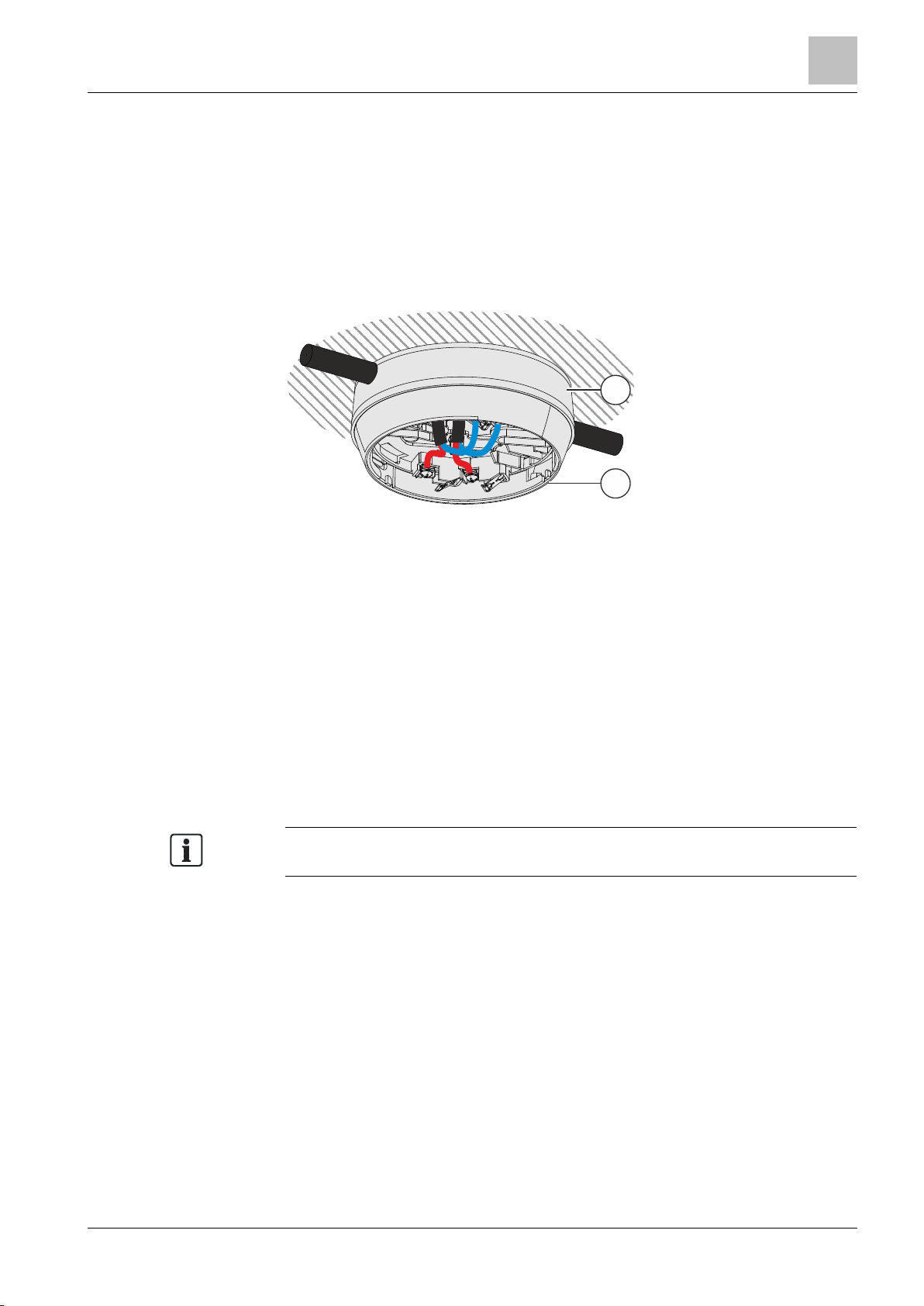
Mounting for surface-mounted cable entry:
1. Break out the areas required for cable entry in base attachment BA720 (1).
2. Insert the cables into the base attachment BA720 (1) through the broken-out
areas.
3. Install the base attachment BA720 (1) on the ceiling together with a detector
base (2).
4. Connect the cables in the detector base (2).
Figure 6: Surface-mounted cable entry with base attachment BA720
1 Base attachment BA720 2 Detector base DB72x
5.6 Base attachment wet BA721
Base attachment wet BA721 is for surface-mounted feed lines in humid and cold
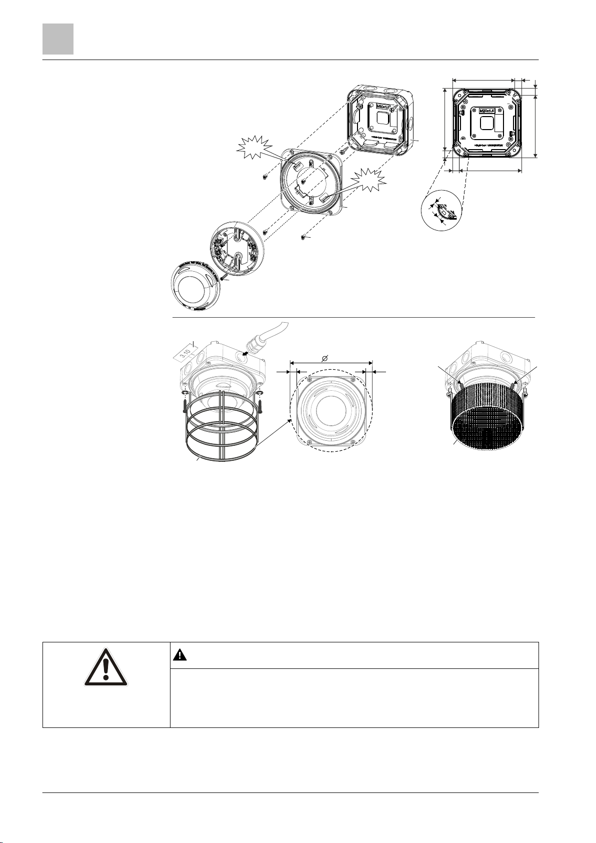
environments. The cables are inserted using M20 x 1.5 metal cable glands (Fig. 3).
Protective cages DBZ1194/FDBZ294 can be installed on 'base attachment wet
BA721'.
● Protective cage DBZ1194 (Fig. 3) protects the detector against mechanical
damage.
● EMC-protective cage FDBZ294 (Fig. 4) protects the detector against
mechanical damage and electromagnetic fields.
attachment wet BA721!
You will find information on connecting detector heating unit FDBH291 in the
'Connection of the detector heating unit [➙ 51]' chapter.
41 | 6
2015-05-04
Page 42
4BMounting / Installation
30BBase attachment wet BA721
5
42
Building Technologies A6V10212047_m_en_--
Fire Safety
WARNING
Danger of falling
● Only use detector exchanger DX791 as an installation tool.
122
122
13
13
122
122
13
13
160
13
13
Fig. 1
Fig. 2
Fig. 3
Fig. 4
A
A
DB110xx
DB721
DB721D
DBZ1194
FDBZ294
1x
1x
4x
2x
Click
DBZ1193A
4.5
7.5
A
Click
Figure 7: Installation and removal of protective cages and designation plates on base attachment wet
Fig. 1
Installation of base attachment wet BA721
● Installation on back box on substructure (2 screws)
● Installation of housing cover on back box (4 screws)
BA721
● Installation of detector base (2 screws)
Fig. 2
Fig. 3
Master gauge for recesses
Installation of protective cage DBZ1194, M20 x 1.5 metal cable gland, designation plate
DBZ1193A
Fig. 4
Installation of EMC-protective cage FDBZ294
Danger of injury
● When installing, use a secured ladder or work platform.
| 64
2015-05-04
Page 43

4BMounting / Installation
30BBase attachment wet BA721
5
64
Building Technologies
A6V10212047_m_en_--
Fire Safety
Installation (Fig. 1 and Fig. 2)
1. Install the M20 x 1.5 metal cable gland(s) in the back box of the base
attachment wet.
2. Fit the back box securely to the substructure with 2 screws (detail A).
3. Screw the housing cover to the back box with the 4 screws.
4. Push the detector base into base attachment wet BA721.
You must be able to hear the detector base click into place.
5. Screw the detector base securely onto base attachment wet BA721 using
2 screws.
Removing the detector base
1. Loosen the two screws on the detector base.
2. Disengage the lock with a screwdriver ('click').
3. Remove the detector base from base attachment wet BA721.
See also
Detector heating unit FDBH291 [➙ 50]
Base attachment wet BA721 [➙ 28]
Protective cage DBZ1194 [➙ 29]
EMC-protective cage FDBZ294 [➙ 29]
Detector heating unit FDBH291 [➙ 28]
43 |
2015-05-04
Page 44
4BMounting / Installation
31BDetector locking device LP720
5
44
Building Technologies A6V10212047_m_en_--
Fire Safety
1.
2.
A
B
5.7 Detector locking device LP720
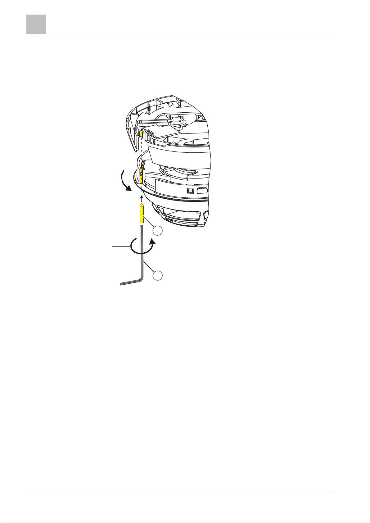
A point detector can be protected against theft with the detector locking device
LP720.
Figure 8: Installing the detector locking device LP720
A Set screw M3 x 12 mm B Allen key
1. Insert the point detector into the detector base.
2. Using the Allen key provided, insert the set screw through the hole in the
detector housing and tighten.
| 64
2015-05-04
Page 45
4BMounting / Installation
32BDesignation plate FDBZ291
5
64
Building Technologies
A6V10212047_m_en_--
Fire Safety
If the detector base seal RS720 is being used, it is not possible to install the
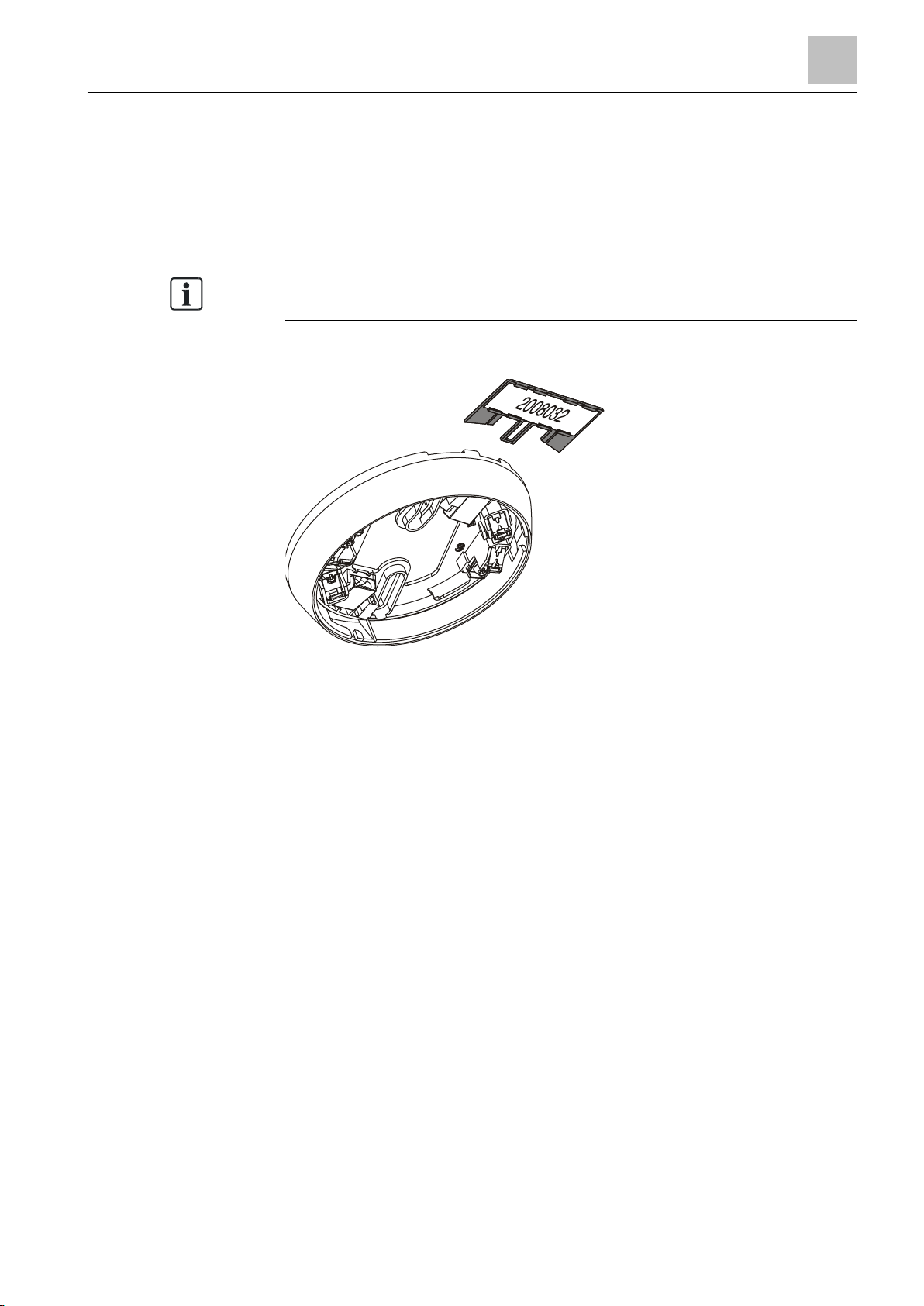
5.8 Designation plate FDBZ291
1. Label designation plate FDBZ291 with location address of point detector.
2. Attach designation plate FDBZ291 to detector base DB72x or sounder base
DBS720.
designation plate FDBZ291.
Figure 9: Installation of designation plate FDBZ291
45 |
2015-05-04
Page 46
4BMounting / Installation
33BCable entry
5
46
Building Technologies A6V10212047_m_en_--
Fire Safety
Terminal name
Connection
NOTICE
Incorrect laying of cables
● The bare length of the cables is approximately 8…10 mm.
5.9 Cable entry
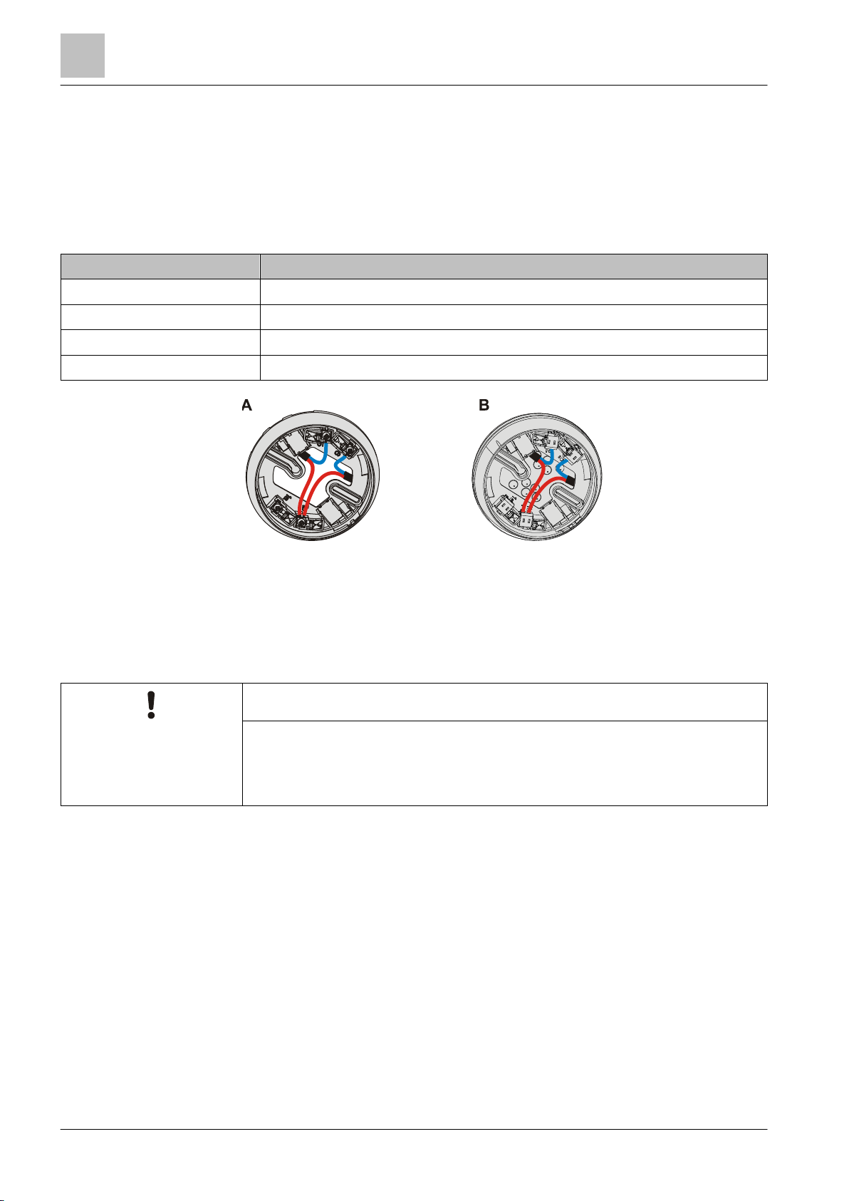
The detector bases DB72x have four terminals.
● A maximum of 2 cables may be connected to each screw terminal.
● Only one cable may be connected to each spring clip.
2
The cable cross section of the terminals is 0.2…1.6 mm
1a +Connection for external alarm indicator
1b +C-NET IN and OUT
5 -C-NET IN or OUT / -external alarm indicator
6 -C-NET IN or OUT / -external alarm indicator
.
Figure 10: Detector base with screw terminals (A) and spring clips (B)
A Screw terminals in the detector base DB721/DB720
B Spring clips in the detector base DB722
Damage to cables and difficulties when installing the point detector
● The cable loops must be placed flat in the base bottom.
| 64
2015-05-04
Page 47

4BMounting / Installation
34BDetector lines
5
64
Building Technologies
A6V10212047_m_en_--
Fire Safety
5.9.1 Auxiliary terminals DBZ1190-AA/-AB
Use the following auxiliary terminals for multiple connections:
● DBZ1190-AB connection terminal 1…2.5 mm²
● DBZ1190-AA micro terminal 0.28…0.5 mm²
Figure 11: Detector base with connection terminals and micro terminals
See also
Connection terminal DBZ1190-AB [➙ 30]
Micro terminal DBZ1190-AA [➙ 29]
5.10 Detector lines
5.10.1 Connection diagram, addressed
Cables and topology
● The connection is established from base to base using twisted or non-twisted
wire pairs.
● Wherever possible use twisted, unshielded cables.
● Shielded cables are only required in special cases, such as strong high-
frequency fields.
● You have the option of using the following types of line:
– Loops
– Stub lines
– Stub line as a branch of a loop
Connecting external alarm indicators FDAI91 / FDAI92 / FDAI93
Observe the following points when connecting external alarm indicators:
● Wherever possible use twisted, unshielded cables.
● Connect a maximum of two external alarm indicators to one detector.
● If a cable with shielding is used to connect the external alarm indicator, this
shielding must be linked to the shielding of the detector bus.
The shielding must not be linked to the external alarm indicator itself.
47 |
2015-05-04
Page 48
4BMounting / Installation
34BDetector lines
5
48
Building Technologies A6V10212047_m_en_--
Fire Safety
The option described is possible in loops and stub lines!
1a 1b
5 6
1a 1b
5 6
1a 1b
5 6
1a 1b
5 6
1a 1b
5 6
+
–
+
–
+
–
2
2
2
2
2
1
3
4
4
+
–
7
8
5
6
5
6
+
–
4
3
3
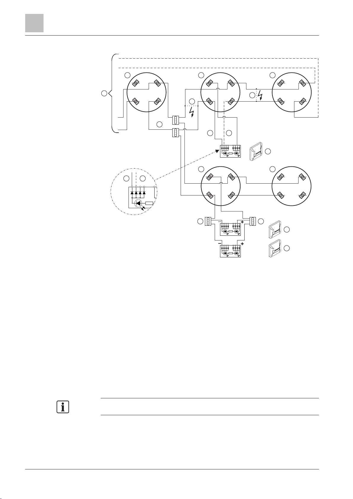
C-NET connection diagram
Figure 12: Connection diagram for addressed detector lines
1 Control panel 5 Cable –EAI6
2 Detector base DB72x, sounder base DBS720 6 Cable –EAI5 (optional)
3 Auxiliary terminal DBZ1190-xx 7 Short circuit (error)
4 External alarm indicator 8 Short circuit (error)
The alarm indicator connected will continue to function correctly in the event of a
short-circuit occurring at position '7' on the connection diagram. The alarm indicator
is triggered by cable –EAI6.
If the short-circuit occurs at position '8' on the connection diagram, the alarm
indicator will no longer be triggered.
As an option, the alarm indicator may also be connected using cable -EAI5.
In this case, the alarm indicator will correctly indicate an alarm even if a shortcircuit occurs at position '8'.
This ensures that the alarm indicator is always functioning correctly.
You will find more detailed information in the fire detection system documentation.
| 64
2015-05-04
Page 49
4BMounting / Installation
35BDetector dust cap
5
64
Building Technologies
A6V10212047_m_en_--
Fire Safety
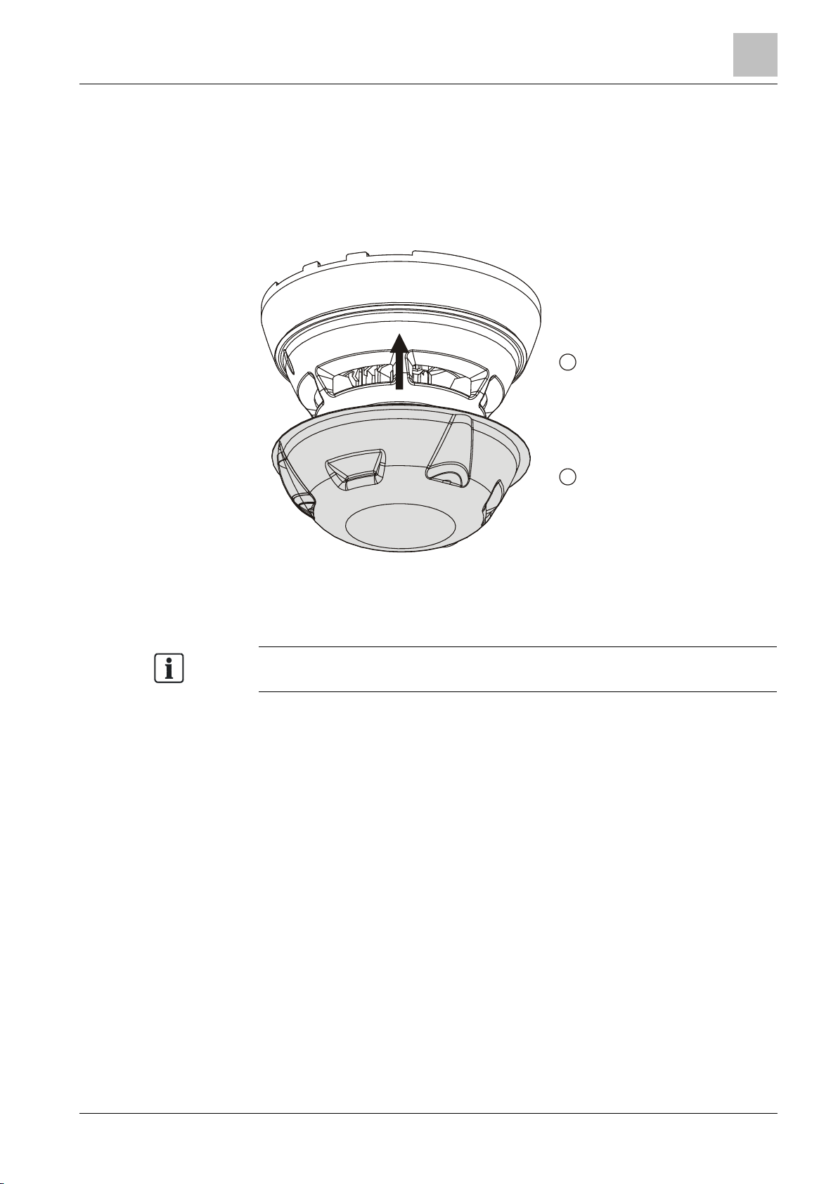
A detector dust cap is provided as part of the scope of supply for each point
1
2
5.11 Detector dust cap
1. Cover the point detector with the detector dust cap during the construction
phase. This will protect the point detector from dust and dirt.
2. Once construction work is complete, remove the detector dust cap from the
point detector.
1 Point detector 2 Detector dust cap
detector.
49 |
2015-05-04
Page 50
4BMounting / Installation
36BDetector heating unit FDBH291
5
50
Building Technologies A6V10212047_m_en_--
Fire Safety
Optimum function of the detector heating unit is only guaranteed with base
5.12 Detector heating unit FDBH291
5.12.1 Installation of the detector heating unit
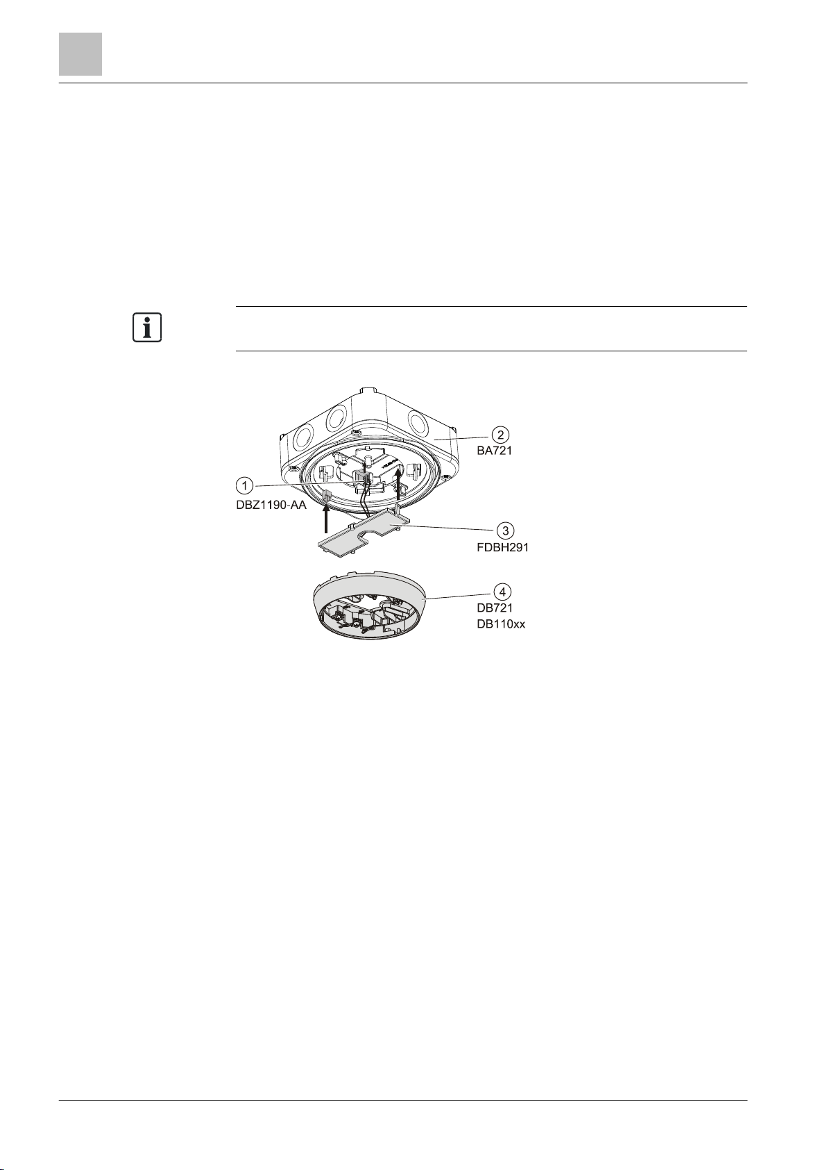
When the detector is exposed to icing or moisture condensation (e.g., in cooling
rooms, attics, loading ramps), detector heating unit FDBH291 is installed in the
detector base. The detector heating unit increases the detector temperature by
approximately 2 °C over the ambient temperature and thus avoids moisture
condensation on the detector.
attachment wet BA721.
Figure 13: Mounting of the detector heating unit FDBH291
1 Micro terminals 3 Detector heating unit
2 Base attachment wet 4 Detector base
| 64
2015-05-04
Page 51
4BMounting / Installation
36BDetector heating unit FDBH291
5
64
Building Technologies
A6V10212047_m_en_--
Fire Safety
NOTICE
Risk of icing
● To ensure smooth operation, the detector must be checked regularly for icing.
+
-
DBZ1190-AA
-
+
LINE
FDBH291
-
+
FDBH291
DBZ1190-AA
1
2
-
+
1a 1b
5 6
1a 1b
5 6
+
DB721
DB110xx
DB721
DB110xx
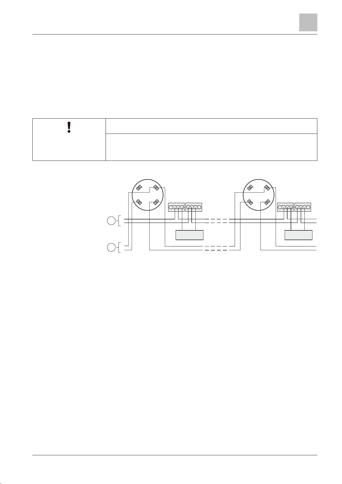
5.12.2 Connection of the detector heating unit
● Connect the cables for the monitored supply from the control panel and the
detector heating unit to the supplied micro terminals DBZ1190-AA.
● The cables can be placed in the same cable harness as the detector line or
separately.
● Several detector heating units can be connected in parallel.
● Detector heating units require a separate supply.
Malfunction
Figure 14: Connection diagram for detector heating unit FDBH291
1 Control panel supply (monitored) 2 Control panel
51 |
2015-05-04
Page 52

5BCommissioning
37BCommissioning on the C-NET
6
52
Building Technologies A6V10212047_m_en_--
Fire Safety
6 Commissioning
6.1 Commissioning on the C-NET
The devices are commissioned via the control panel. The exact procedure is
described in the control panel documentation.
| 64
2015-05-04
Page 53
6BMaintenance / Repair
38BPerformance check
7
64
Building Technologies
A6V10212047_m_en_--
Fire Safety
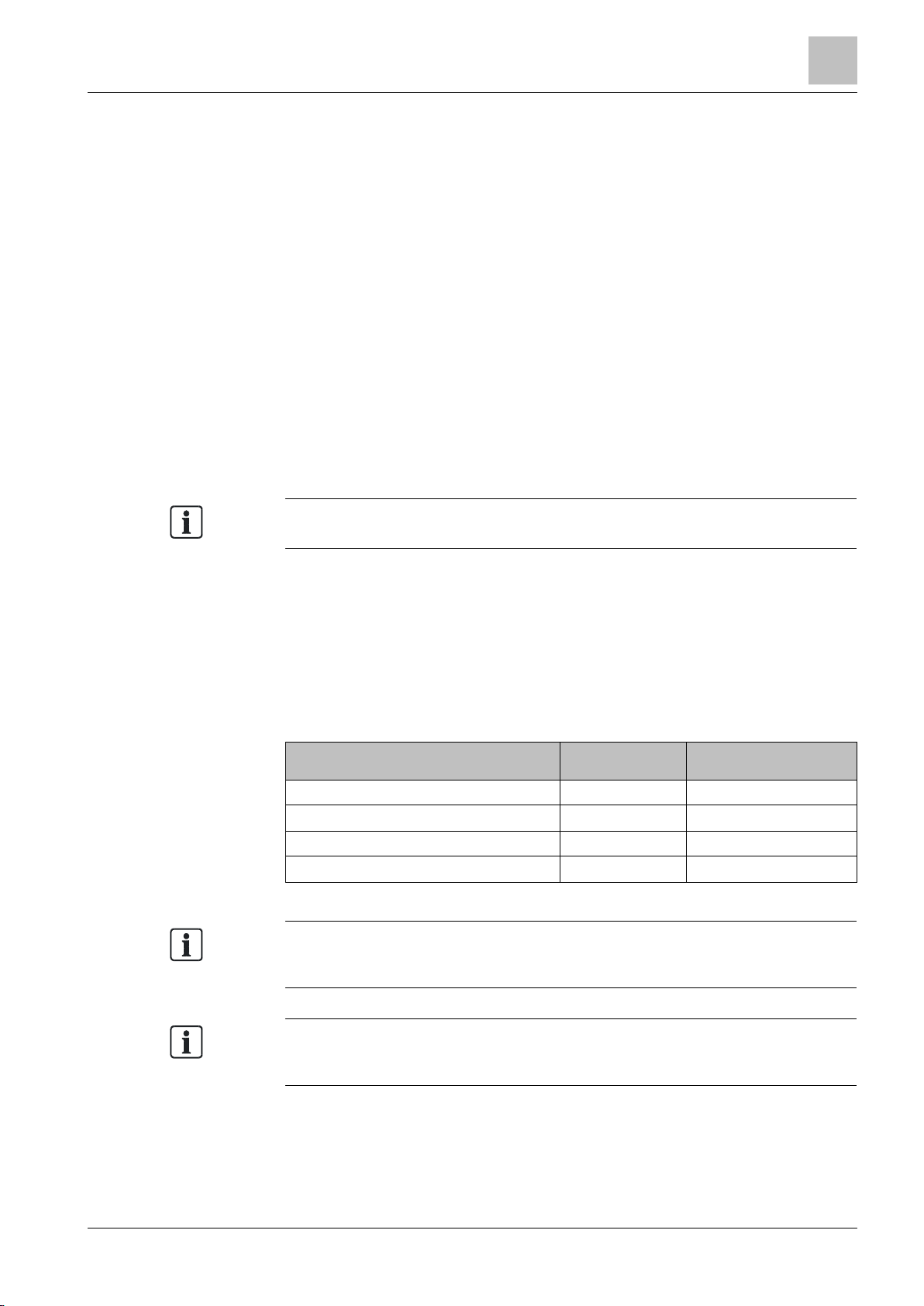
To enable detector testing with test gas or with a hot air fan, the detector must be
Detector
Test gas
Hot air fan / detector tester
RE7T
The flashing behavior of the alarm indicators in test mode is described in the
To trigger a detector using test gas, normally 2…4 gas discharges at intervals of
7 Maintenance / Repair
7.1 Performance check
The selftest automatically subjects the detectors to an extensive electrical
performance check. Regular performance checks of the detectors are required
nonetheless. This may be done with the test gas or hot air fan depending on the
detector type.
Recommendation:
● Check the devices every year.
● Replace heavily soiled or damaged devices.
● All detectors should be replaced after 6 to 8 years of service, depending on the
ambient conditions.
7.2 Testing detectors
switched to test mode.
Depending on the detector, testing may be performed with one or more of the
following accessories:
● Test gas
– REF8-S (recommended)
– REF8
● Hot air fan
● Detector tester RE7T
The following table shows which detectors may be tested with which test aids.
OH720
OP720
HI720
HI722
'Internal alarm indicator in the case of ES <10 [➙ 21]' and 'Extended flashing
X X
X –
– X
– X
behavior of alarm indicators in the case of ES ≥10 [➙ 22]' chapters.
approx. 2 seconds are required. When the detector is in test mode, activation
takes place after approximately 10 seconds.
53 |
2015-05-04
Page 54

7BSpecifications
40BMulti-sensor smoke detector technical data
8
54
Building Technologies A6V10212047_m_en_--
Fire Safety
Detector line
Line separator
External alarm indicators
8 Specifications
Temperature = 25 °C
Air pressure = 1000 hPa (750 Torr)
8.1 Multi-sensor smoke detector technical data
The following section lists the technical data for the multisensor smoke detector
OH720.
You will find information on approvals, CE marking, and the relevant EU directives
for this device (these devices) in the following document(s); see 'Applicable
documents' chapter:
Unless otherwise mentioned, the following data applies:
Operating voltage (modulated) DC 12…33 V
Operating current (quiescent) Typ. 230 μA
Maximum current connection factor 1
Quiescent current connection factor 1
Address connection factor 1
Separator connector factor 1
Protocol C-NET
Compatibility See 'List of compatibility'
Line voltage:
● Nominal DC 32 V (= V
● Minimum DC 12 V (= V
● Maximum DC 33 V (= V
Voltage at which the line separator opens:
● Minimum DC 7.5 V (= V
● Maximum DC 10.5 V (= V
Permanent current when switches are closed: Max. 1.5 A (= I
Switching current (e.g., in the event of a short-
Leakage current when switches are open: Max. 1 mA (= I
Serial impedance when switches are closed: Max. 0.4 Ω (= Z
The line separator is closed via an actuation signal from the control panel. Required line
Number of external alarm indicators that can
Voltage DC 9…30 V
Current 10…16 mA
● Document A6V10202198
circuit)
voltage: DC 12...33 V (normal range)
be connected
Max. 2 A (= I
Max. 2
nom
min
max
SO min
S max
)
)
)
SO max
C max
)
L max
C max
)
)
)
)
)
| 64
2015-05-04
Page 55

7BSpecifications
40BMulti-sensor smoke detector technical data
8
64
Building Technologies
A6V10212047_m_en_--
Fire Safety
Device characteristics
Connections
Ambient conditions
Mechanical data
Standards
Response sensitivity
at 0.2 m/s (typ.)
Permissible wind speed Max. 5 m/s
Compensation speed ≤1/45 voltage increase for detection/h
Flashing interval times AI:
● Bright 15 ms
● Dark 1 s
Detector line and external alarm indicators:
● Design Screw terminal
● Cable cross section 2x 0.2…1.6 mm
Operating temperature/permissible ambient
temperature
Storage temperature -30…+70 °C
Air humidity ≤95 % rel.
Protection categories according to EN 60529 /
IEC 60529:
● Base DB721, DB720, DBS720
(all installation types)
● Base DB721, DB720, DBS720 with
detector base seal RS720
● Base DB722 IP42
● Base attachment wet BA721 IP44
Electromagnetic compatibility:
● 10 kHz…1.8 GHz 50 V/m
● 1.8 GHz…2.5 GHz 20 V/m
Color ∼RAL 9010 pure white
Dimensions See the 'Dimensions [➙ 60]' chapter
European standards ● EN 54-7
International standards ● IEC 60092-504
2.5 or 3.5 %/m (depending on the
parameter set)
2
-10…+55 °C
IP40
IP42
● EN 54-17
● CEA 4021
● IEC 60533
See also
Applicable documents [➙ 7]
55 |
2015-05-04
Page 56

7BSpecifications
41BSmoke detector technical data
8
56
Building Technologies A6V10212047_m_en_--
Fire Safety
Detector line
Line separator
External alarm indicators
Device characteristics
8.2 Smoke detector technical data
The following section lists the technical data for the smoke detector OP720.
You will find information on approvals, CE marking, and the relevant EU directives
for this device (these devices) in the following document(s); see 'Applicable
documents' chapter:
Operating voltage (modulated) DC 12…33 V
Operating current (quiescent) Typ. 220 μA
Maximum current connection factor 1
Quiescent current connection factor 1
Address connection factor 1
Separator connector factor 1
Protocol C-NET
Compatibility See 'List of compatibility'
Line voltage:
● Nominal DC 32 V (= V
● Minimum DC 12 V (= V
● Maximum DC 33 V (= V
Voltage at which the line separator opens:
● Minimum DC 7.5 V (= V
● Maximum DC 10.5 V (= V
Permanent current when switches are closed: Max. 1.5 A (= I
Switching current (e.g., in the event of a short-
Leakage current when switches are open: Max. 1 mA (= I
Serial impedance when switches are closed: Max. 0.4 Ω (= Z
The line separator is closed via an actuation signal from the control panel. Required line
Number of external alarm indicators that can
Voltage DC 9…30 V
Current 10…16 mA
Response sensitivity
Permissible wind speed Max. 5 m/s
Compensation speed ≤1/45 voltage increase for detection/h
Flashing interval times AI:
● Bright 15 ms
● Dark 1 s
● Document A6V10202198
circuit)
voltage: DC 12...33 V (normal range)
be connected
at 0.2 m/s (typ.)
)
nom
)
min
)
max
)
SO min
)
SO max
)
C max
Max. 2 A (= I
S max
L max
C max
)
)
)
Max. 2
1.8 or 2.5 %/m (depending on the
parameter set)
| 64
2015-05-04
Page 57

7BSpecifications
41BSmoke detector technical data
8
64
Building Technologies
A6V10212047_m_en_--
Fire Safety
Connections
Ambient conditions
Mechanical data
Standards
Detector line and external alarm indicators:
● Design Screw terminal
● Cable cross section 2x 0.2…1.6 mm
Operating temperature/permissible ambient
temperature
Storage temperature -30…+70 °C
Air humidity ≤95 % rel.
Protection categories according to EN 60529 /
IEC 60529:
● Base DB721, DB720, DBS720
(all installation types)
● Base DB721, DB720, DBS720 with
detector base seal RS720
● Base DB722 IP42
● Base attachment wet BA721 IP44
Electromagnetic compatibility:
● 10 kHz…1.8 GHz 50 V/m
● 1.8 GHz…2.5 GHz 20 V/m
Color ∼RAL 9010 pure white
Dimensions See the 'Dimensions [➙ 60]' chapter
European standards ● EN 54-7
International standards ● IEC 60092-504
-10…+55 °C
IP40
IP42
● EN 54-17
● IEC 60533
2
See also
Applicable documents [➙ 7]
57 |
2015-05-04
Page 58

7BSpecifications
42BHeat detector technical data
8
58
Building Technologies A6V10212047_m_en_--
Fire Safety
Detector line
Line separator
External alarm indicators
Device characteristics
8.3 Heat detector technical data
The following section lists the technical data for the heat detectors HI720 and
HI722.
You will find information on approvals, CE marking, and the relevant EU directives
for this device (these devices) in the following document(s); see 'Applicable
documents' chapter:
Operating voltage (modulated) DC 12…33 V
Operating current (quiescent) Typ. 200 μA
Maximum current connection factor 1
Quiescent current connection factor 1
Address connection factor 1
Separator connector factor 1
Protocol C-NET
Compatibility See 'List of compatibility'
Line voltage:
● Nominal DC 32 V (= V
● Minimum DC 12 V (= V
● Maximum DC 33 V (= V
Voltage at which the line separator opens:
● Minimum DC 7.5 V (= V
● Maximum DC 10.5 V (= V
Permanent current when switches are closed: Max. 1.5 A (= I
Switching current (e.g., in the event of a short-
Leakage current when switches are open: Max. 1 mA (= I
Serial impedance when switches are closed: Max. 0.4 Ω (= Z
The line separator is closed via an actuation signal from the control panel. Required line
Number of external alarm indicators that can be
Voltage DC 9…30 V
Current 10…16 mA
Static response temperature with parameter
● A2S (typ.): 60 °C
● A2R (typ.): 60 °C
Flashing interval times AI:
● Bright 15 ms
● Dark 1 s
● Document A6V10202198
circuit)
voltage: DC 12...33 V (normal range)
connected
set:
Max. 2 A (= I
Max. 2
nom
min
max
SO min
S max
)
)
)
SO max
C max
)
L max
C max
)
)
)
)
)
| 64
2015-05-04
Page 59

7BSpecifications
42BHeat detector technical data
8
64
Building Technologies
A6V10212047_m_en_--
Fire Safety
Connections
Ambient conditions
Mechanical data
Standards
Detector line and external alarm indicators:
● Design Screw terminal
● Cable cross section 2x 0.2…1.6 mm
Operating temperature/permissible ambient
temperature
Storage temperature -30…+70 °C
Air humidity ≤95 % rel.
Protection categories according to EN 60529 /
IEC 60529:
● Base DB721, DB720, DBS720
(all installation types)
● Base DB721, DB720, DBS720 with
detector base seal RS720
● Base DB722 IP42
● Base attachment wet BA721 IP44
Electromagnetic compatibility:
● 10 kHz…2.5 GHz 50 V/m
Color ∼RAL 9010 pure white
Dimensions See the 'Dimensions [➙ 60]' chapter
European standards ● EN 54-5
International standards ● IEC 60092-504
-10…+55 °C
IP40
IP42
● EN 54-17
● IEC 60533
2
See also
Applicable documents [➙ 7]
59 |
2015-05-04
Page 60
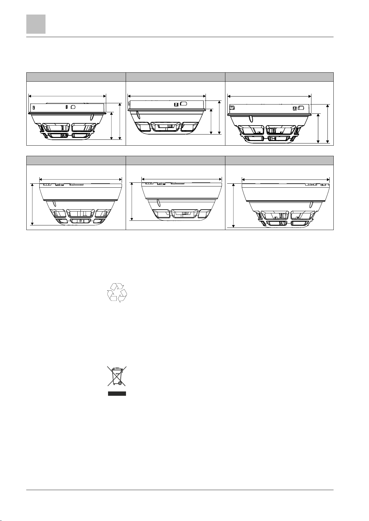
7BSpecifications
43BDimensions
8
60
Building Technologies A6V10212047_m_en_--
Fire Safety
OH720
OP720
HI720, HI722
OH720 with base
OP720 with base
HI720, HI722 with base
105
37
49
105
34
45
105
37
49
117
59
117
56
117
59
8.4 Dimensions
8.5 Environmental compatibility
This equipment is manufactured using materials and procedures which
comply with current environmental protection standards as best as
possible. More specifically, the following measures have been
undertaken:
● Use of reusable materials
● Use of halogen-free plastics
● Electronic parts and synthetic materials can be separated
Larger plastic parts are labeled according to ISO 11469 and ISO 1043.
The plastics can be separated and recycled on this basis.
Electronic parts and batteries must not be disposed of with domestic
waste.
● Take electronic parts and batteries to local collection points or
recycling centers.
● Contact local authorities for more information.
● Observe national requirements for disposing of electronic parts
and batteries.
| 64
2015-05-04
Page 61

Index
64
Building Technologies
A6V10212047_m_en_--
Fire Safety
Index
A
Alarm indicator
external 23
Approvals 54, 56, 58
Auxiliary terminals
Connection terminal 47
Micro terminal 47
C
Cables 47
CE marking 54, 56, 58
C-NET
Commissioning detectors 52
Collective behavior
Degraded mode operation 24
Commissioning detectors 52
Compatibility 31
Compatibility with control panels 31
Connection diagram 47
External alarm indicators 47
Connection terminal 47
Control panel 52
D
Danger levels 20
Degraded mode operation
Collective behavior 24
Fire control panel failure 24
Designation plate
Detector base 45
Installation 45
Sounder base 45
Detector
Performance check 53
Detector base 25
Detector base seal
Installation 39
Detector dust cap 49
Detector exchanger 35
Detector heating unit
Mounting 50
Detector line
Connection diagram 47
Detector locking device
Mounting 44
Diagnosis levels 20
Fault 20
Normal 20
Observe information 20
Replacement necessary 20
Replacement recommended 20
Disposal 60
Documentation for fire detection system 7, 22
Download center
URL 7
E
Environmental compatibility 60
ES
Product version 16
EU directives 54, 56, 58
External alarm indicators 23
61 |
2015-05-04
Page 62

Index
62
Building Technologies A6V10212047_m_en_--
Fire Safety
F
Fire control panel failure
Degraded mode operation 24
Flashing behavior
Steady-on 22
Flashing mode
Internal alarm indicator 22
Flashing pattern
Configuration 22
Internal alarm indicator 22
H
Heat detector 19
Static 15
Static and differential 15
Hot air fan 53
I
Internal alarm indicator 21
Alarm 21
Alarm in test mode 21
L
Line separator
Function 21
List of compatibility 24, 31
Loop 47
M
Maintenance intervals 53
Micro terminal 47
Multi-sensor smoke detector 15, 17
O
Original language
Source language 5
S
Scope 5
Screw terminals 37, 46
Short-circuit
Line separator 21
Smoke detector 15, 18
Sounder base 25
Source language 5
Spring clips 37, 46
Standards 55, 57, 59
Steady-on
Internal alarm indicator 22
Stub line 47
T
Terminals
Assignment 46
Test gas
REF8 53
REF8-S 53
Test mode 23
Testing equipment
Hot air fan 23, 53
Test gas 53
Test gas REF8 23
Test gas REF8-S 23
Topology 47
Type plate
Product version 16
W
Wide-spectrum smoke detector 18
P
Packaging label
Product version 16
Parameter sets 20
Heat detector 33
Multi-sensor smoke detector 31
Smoke detector 32
Performance check 53
Product label
Product version 16
R
Recycling 60
Required space 35
| 64
2015-05-04
Page 63

Index
64
Building Technologies
A6V10212047_m_en_--
Fire Safety
63 |
2015-05-04
Page 64

Issued by
Edition: 2015-05-04
Register 2
Siemens Switzerland Ltd
Building Technologies Division
International Headquarters
Gubelstrasse 22
CH-6301 Zug
+41 41-724 24 24
www.siemens.com/buildingtechnologies
Document ID: A6V10212047_m_en_-- Manual FD720
© Siemens Switzerland Ltd, 2008
Technical specifications and availability subject to change without notice.
 Loading...