

Page 1
Building Technologies
Automatic fire detectors
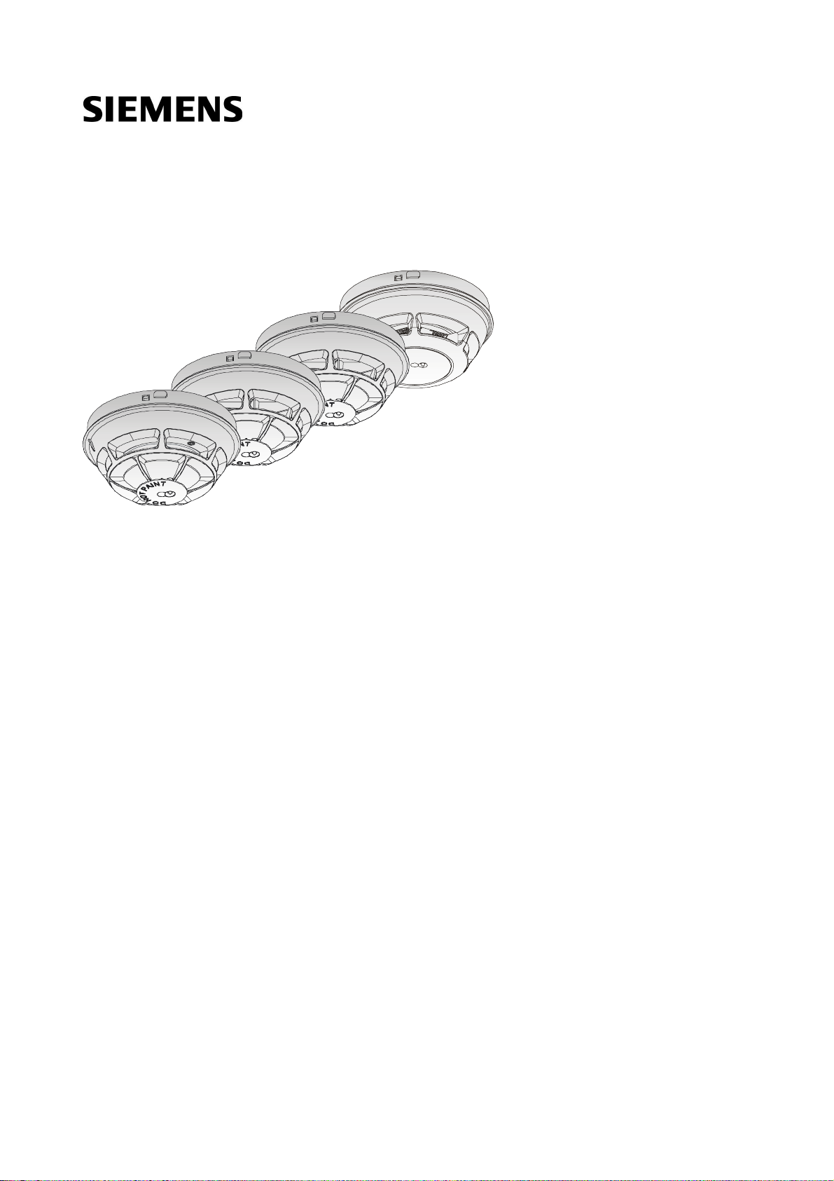
OH110, OP110, HI110, HI112
Technica l Manual
A6V10316298_e_en_-2014-05-21 Control Products and Systems
Page 2

Legal notice
Legal notice
Technical specifications and availability subject to change without notice.
© 2012-2014 Copyright by Siemens Switzerland Ltd
Transmitt al, reproduction, dissemination and/or editing of this doc ument as well as
utilization of its contents and communication thereof to others without expr ess
authorization are prohibited. Offenders will be held liable for payment of damages.
All rights creat ed by patent grant or registration of a utility model or design patent
are reserved.
Issued by:
Siemens Switzerland Ltd.
Infrastructure & Cities Sector
Building Technologies Div ision
International Headquarters
Gubelstrasse 22
CH-6301 Zug
Tel. +41 41 724-2424
www.siemens.com/buildingtechnologies
Edition: 2014-05-21
Document ID: A6V10316298_e_en_--
2
Building Technologies A6V10316298_e_en_--
Fire Safety 2014-05-21
Page 3

Table of contents
1 About this document ......................................................................................5
1.1 Applica ble docu ments .......................................................................................7
1.2 Download center...............................................................................................7
1.3 Technica l terms ................................................................................................7
1.4 History of changes ............................................................................................8
2 Safety ..............................................................................................................9
2.1 Safety instru ct ions ............................................................................................9
2.2 Safety regu lat ions for the meth od of operat ion ................................................ 11
2.3 Standa rds an d directives co mp lied with .......................................................... 13
2.4 Releas e Notes ................................................................................................ 13
3 Structur e and function ................................................................................. 14
3.1 Overview ........................................................................................................ 14
3.1.1 Details for ordering ........................................................................... 14
3.1.2 Product version ES .......................................................................... 15
3.2 Point dete ctor ................................................................................................. 16
3.2.1 Multi-s ensor fire detecto r .................................................................. 16
3.2.2 Smoke detecto r................................................................................ 17
3.2.3 Heat detecto r ................................................................................... 18
3.3 Function ......................................................................................................... 19
3.3.1 Parame ter sets ................................................................................ 19
3.3.2 Diagnosis levels ............................................................................... 19
3.3.3 Interna l alarm indicator ..................................................................... 20
3.3.4 Conne ction for external alar m indicators ........................................... 21
3.3.5 Test mode ....................................................................................... 21
3.4 Mechanical setup ............................................................................................ 22
3.5 Accessories .................................................................................................... 23
3.5.1 Detecto r base (collective) DB110 ..................................................... 23
3.5.2 Detecto r base (collective) DB110D ................................................... 23
3.5.3 Detecto r base (collective) DB110R ................................................... 24
3.5.4 Detecto r base (collective) DB110 RD ................................................ 24
3.5.5 Design ation plate FDBZ29 1 ............................................................. 25
3.5.6 Detecto r base seal RS720 ............................................................... 25
3.5.7 Base attachmen t BA720 .................................................................. 25
3.5.8 Base attachment wet BA721 ............................................................ 26
3.5.9 Design ation plate DBZ119 3A ........................................................... 26
3.5.10 Detecto r heating unit FDBH291 ........................................................ 26
3.5.11 Protect ive cage DBZ11 94 ................................................................ 27
3.5.12 EMC-pro tective cage FDBZ29 4 ........................................................ 27
3.5.13 Detecto r locking device LP720 ......................................................... 27
3.5.14 Micro termina l DBZ1 190-AA ............................................................. 28
3.5.15 Conne ction terminal DBZ1190-A B.................................................... 28
Building Technologies A6V10316298_e_en_-Fire Safety 2014-05-21
3
Page 4

4 Planning ........................................................................................................ 29
4.1 Compatibility ................................................................................................... 29
4.2 Multi-s ens or fire detecto r ................................................................................ 29
4.2.1 Parame ter sets ................................................................................ 2 9
4.2.2 Specifica tions .................................................................................. 30
4.3 Smoke detector .............................................................................................. 3 1
4.3.1 Parame ter sets ................................................................................ 3 1
4.3.2 Specifica tions .................................................................................. 31
4.4 Heat detector .................................................................................................. 32
4.4.1 Parame ter sets ................................................................................ 3 2
4.4.2 Specifica tions .................................................................................. 33
5 Mount ing / Installatio n .................................................................................. 34
5.1 Required space .............................................................................................. 3 4
5.2 Detecto r base (collec t ive) D B1 1 0 / DB11 0 x / DB11 0 xx .................................... 35
5.3 Detecto r base seal RS720 .............................................................................. 36
5.4 Base attachment BA720 ................................................................................. 37
5.5 Base attachment wet BA721 ........................................................................... 39
5.6 Detecto r locking device LP72 0 ........................................................................ 41
5.7 Design ation plate FDBZ291 ............................................................................ 42
5.8 Cable entry ..................................................................................................... 4 3
5.8.1 Auxiliar y terminals DBZ11 90-A A/-AB ............................................... 43
5.9 Detecto r dus t cap ........................................................................................... 4 4
5.10 Detecto r heating unit FDBH291 ...................................................................... 45
5.10.1 Installat ion of the detecto r heat ing unit ............................................. 45
5.10.2 Conne ction of the detector hea ting unit ............................................ 46
5.11 Protect ive cages ............................................................................................. 47
5.11.1 Installat ion of the protect i ve cages ................................................... 47
5.11.2 Ground ing of the EMC-pro tecti ve cage FDBZ294 ............................. 47
5.12 Conne ction diagram ....................................................................................... 48
6 Commissioning............................................................................................. 49
7 Mainte nance / Repair .................................................................................... 5 0
7.1 Performance check ......................................................................................... 50
7.2 Testing the point detec tor ............................................................................... 50
8 Specifications ............................................................................................... 51
8.1 Technica l data for multi-sens or fire detector OH110 ........................................ 51
8.2 Technica l data for s moke de tec tor OP1 10 ...................................................... 52
8.3 Technica l data for heat detectors HI11 0 / HI112 .............................................. 54
8.4 Dimens ions .................................................................................................... 5 6
8.5 Environ mental compatib ility and dispo sal ........................................................ 56
Index ............................................................................................................. 5 7
4
Building Technologies A6V10316298_e_en_--
Fire Safety 2014-05-21
Page 5

Applicable documents
1 About this document
Goal and purpose
This document contains information on automat ic fire detectors. Following the
instructions consistently will ensur e that the product can be used safely and without
any problems.
Scope
The document is valid f or the following automatic f ire detectors:
l OH110
l OP110
l HI110
l HI112
Target groups
The information in this document is intended f or the following target groups:
Target group Activity Qualificat ion
About this document
1
Product Manager
Project Manager
Project engineer
Installation personnel
Maintenance personnel l Carries out all maintenance work.
l Is responsible for information passing
between the manufacturer and regional
company.
l Coordinates the flow of information
between the individual groups of people
involved in a project.
l Coordinates the deployment of all
persons and resources involved in the
project according to schedule .
l Provides the information required to run
the project.
l Sets parameters for product depending
on specific national and/or customer
requirements.
l Checks operability and approves the
product for commissioning at the place
of installation.
l Is responsible for trouble-shooting.
l Assembles and installs the product
components at the place of installation.
l Carries out a performance check
following installation.
l Checks that the products are in perfect
working order.
l Searches for and corrects malfunctions.
l Has obtained suitable specialist training
for the function and for the products.
l Has attended the training courses for
Product Managers.
l Has obtained suitable specialist training
for the function and for the products.
l Has attended the training courses for
Project Managers.
l Has obtained suitable specialist training
for the function and for the products.
l Has attended the training courses for
Product Engineer.
l Has received specialist training in the
area of building installation technology
or electrical installations.
l Has obtained suitable specialist training
for the function and for the products.
Building Technologies A6V10316298_e_en_-Fire Safety 2014-05-21
5
Page 6

About this document
Applicable documents
The 'i' symbol identif ies supplementary information and tips for an easier way of
1
Reference document and source language
l The source language of this document is German (de).
l T he reference version of this document is the international version in English.
The international ver sion is not localized.
The reference document has the following designation:
ID_x_en_-x = version, en = English, -- = international
Document identification
The document ID is structured as follows:
ID code Examples
ID_ModificationIndex_Language_COUNTRY
-- = multilingual or international
A6V10215123_a_de_DE
A6V10215123_a_en_-A6V10315123_a_--_--
Date format
The date format in the document corresponds to the recomm endation of
international standard ISO 8601 (format YYYY-MM-DD).
Conventions for text marking
Markups
Special markups are shown in this document as follows:
⊳ Requirement for a behavior instruction
1.
2.
– Version, option, or detailed information for a behavior instruction
⇨ Intermediate result of a behavior instruction
⇨ End result of a behavior instruction
Behavior instruction with at least two operation sequences
l Numbered lists and behavior instructions with an operation
sequence
[➙ X] Reference to a page number
'Text' Quotation, reproduced identically
<Key> Identificat ion of keys
Supplementary information and tips
working.
6
Building Technologies A6V10316298_e_en_--
Fire Safety 2014-05-21
Page 7

Applicable documents
1.1 Applicable documents
You will also
find information about search variants and links t o mobile
Document ID Name
008331 List of compatibility (for 'Sinteso™' product line)
A6V10201731
A6V10301051
A6V10316300
A6V10406006
Installation Detector exchanger DX791, adapter for detector
exchanger FDUD491
Data sheet Automatic fire detectors OH110, OP110, HI110,
HI112
Installation Detector base (collective) DB110, DB110D,
DB110R, DB110RD, detector base seal RS720, detector
locking device LP720, base attachment BA720
Installation Base attachment wet BA721, Detector designation
plate DBZ1193A, Protective cage DBZ1194, EMC-protective
cage FDBZ294
Please also observe the documentation for your fire detection system.
1.2 Download center
You can download various types of documents, such as data sheets, installation
instructions, and license texts v ia the following Internet address:
http://siemens.com/bt/download
About this document
1
l Ent er the document ID in the 'Find by keywords' input box.
applications (apps) for various systems on the home page.
1.3 Technical terms
Term Explanation
AI Alarm indic a tor
ES Product version
Building Technologies A6V10316298_e_en_-Fire Safety 2014-05-21
7
Page 8

About this document
History of changes
The first edition of a language version or a country variant may, for example, be
1
1.4 History of changes
The reference docum ent's version applies to all languages into which the reference
document is trans lated.
version 'd' inst ead of 'a' if the reference document is already this version.
The table below shows this document's history of changes:
Modification index Edition date Brief description
e 2014-05-21 Editorial revision
d 2014-02-10
c 2013-08-31
b 2012-06-15
a 2012-04 First edition
Data sheet in 'Applicable documents' chapter added; base
attachment wet BA721, designation plate DBZ1193A, protective cage
DBZ1194, EMC-protective cage FDBZ294, and detector heating unit
FDBH291 added; 'Download center' chapter added
Information on LPCB approvals for OH110, HI110, and HI112 point
detectors
CPD/G number for OH110/OP110 added, new date format in line with
ISO 8601 (yyyy-mm-dd)
The table below shows the published language versions with the corresponding
modification index:
Modification index en_-- de_-- fr_-- it_-- es_--
e x x x x x
d x x x x x
c X X X X X
b X X X X X
a X X X X X
X = published
– = no publication with this modification index
8
Building Technologies A6V10316298_e_en_--
Fire Safety 2014-05-21
Page 9
Safety instructions
2 Safety
Signal word
Danger level
2.1 Safety instructions
The safety notices mus t be observed in order to protect people and property.
The safety notices in this document contain the following elements:
l Symbol for danger
l Signal word
l Nature and origin of the danger
l Consequences if the danger occurs
l Measures or prohibit ions for danger avoidance
Symbol for danger
This is the symbol for danger. It warns of risks of injury.
Follow all measures ident ified by this symbol to avoid injury or deat h.
Safety
2
Additional dan ger symbols
These symbols indic ate general dangers, the type of danger or poss ible
consequences, measures and prohibitions, examples of which are shown in the
following table:
General danger Explosive atmosphere
Voltage/electric shock Laser light
Battery Heat
Signal word
The signal word classifies the danger as defined in the following table:
DANGER DANGER identifies a dangerous situation, which will result directly in death or
serious injury if you do not avoid this situation.
WARNING WARNING identifies a dangerous situation, which may result in death or serious
injury if you do not avoid this situation.
CAUTION CAUTION identifies a dangerous situation, which could result in slight to
NOTICE NOTICE
Building Technologies A6V10316298_e_en_-Fire Safety 2014-05-21
moderately serious injury if you do not avoid this situation.
identifies possible damage to property that may result from non-
observance.
9
Page 10

2
Safety instructions
Nature and origin of the danger
●
Measures / prohibit ions for danger avoidance
Nature and origin of the danger
●
Measures / prohibit ions for danger avoidance
Safety
How risk of injury is presented
Information about the risk of injury is shown as follows:
WARNING
Consequences if the danger oc curs
How possible damage to property is presented
Information about possible damage to property is s hown as follows:
NOTICE
Consequences if the danger oc curs
10
Building Technologies A6V10316298_e_en_--
Fire Safety 2014-05-21
Page 11

Safety
Safety regulations for the method of operation
Electrical volt age
regulations.
2.2 Safety regulations for the method of operation
National standards, regulations and legislation
Siemens products ar e developed and produced in compliance with the relevant
European and international safety standards . Should additional national or local
safety standards or legislation concerning the planning, assembly, installation,
operation or disposal of the product apply at the place of operation, then these
must also be taken into account together with the safety regulations in the product
documentation.
Electrical installations
WARNING
Electric shock
● Work on electrical installations may only be carried out by qualified
electricians or by instructed persons work ing under the guidance and
supervision of a qualified electrician, in accordanc e with the electrotechnical
2
l W herever possible disconnect products from the power supply when carrying
out commissioning, maintenance or repair work on them.
l Lock volt-free areas to prevent them being switched back on again by mistake.
l Label the connection terminals with external external voltage using a
'DANGER External voltage' sign.
l Rout e mains connections to products separately and fuse them with their own,
clearly marked fuse.
l F it an easily accessible disconnecting device in accordance with IEC 60950-1
outside the installation.
l Produce earthing as stated in local safet y regulat ions.
Assembly, installation, commissioning and maintenance
l If you require tools such as a ladder, these must be safe and must be intended
for the work in hand.
l W hen starting the fire control panel ensure that unstable conditions cannot
arise.
l Ensure that all points listed in the 'Testing the product operability' section below
are observed.
l You may only set controls to normal function when the product operability has
been completely tested and the system has been handed over to the customer.
Building Technologies A6V10316298_e_en_-Fire Safety 2014-05-21
11
Page 12

2
Safety regulations for the method of operation
Safety
Testing the product operability
l Prevent the remot e transmis sion from trigger ing err oneously.
l I f testing building installations or activating devices from third-party companies,
you must collaborate with the people appointed.
l T he activation of fire control installations for test purposes must not cause
injury to anyone or damage to the building installations. The following
instructions m ust be observed:
– Use the correct potential for activation; this is generally the potential of the
building installation.
– Only check controls up to the interface (relay with blocking opt ion).
– Make sure that only the controls to be tested are activated.
l I nform people before testing the alarm devices and allow for possible panic
responses.
l I nform people about any noise or mist which may be produced.
l Bef ore testing the remote transmission, inform the corresponding alarm and
fault signal receiving stations.
Modifications to the system design and the products
Modifications to the system and to individual products m ay lead to faults,
malfunctioning and safety risks. Written confirmation must be obtained from
Siemens and the corresponding safety bodies for m odifications or additions.
Modules and spare parts
l Components and spare parts must comply with the technical specifications
defined by Siemens. Only use products specified or recommended by
Siemens.
l Only use fuses with t he specified fuse characteristics.
l Wrong battery types and improper battery changing lead to a risk of explosion.
Only use the same battery type or an equivalent battery t ype recommended by
Siemens.
l Bat teries must be disposed of in an environmentally friendly manner. Observe
national guidelines and regulations.
Disregard of the safety regulations
Before they ar e delivered, Siemens products ar e tested to ensure they function
correctly when used properly. Siemens disclaims all liability for damage or injuries
caused by the incorrec t application of the instructions or the disregard of danger
warnings contained in the documentation. This applies in particular to the following
damage:
l Per sonal injuries or damage to property caused by improper use and incorrect
application
l Per sonal injuries or damage to property caused by disregarding safety
instructions in the documentation or on the product
l Personal injury or damage to property caused by poor maintenance or lack of
maintenance
12
Building Technologies A6V10316298_e_en_--
Fire Safety 2014-05-21
Page 13

Standards and directives c
omplied with
2.3 Standards and directives complied with
Limited or non
-
existent fire detection
detection installation.
Incorrect planning and/or configurat ion
detection installation.
A list of the standards and directives complied wit h is available from your Siemens
contact.
2.4 Release Notes
Limitations t o the configuration or use of devices in a fire detection installation with
a particular firmware version are possible.
WARNING
Personal injury and damage to property in the event of a fire.
● Read the 'Release Notes' before you plan and/or configure a fire detection
installation.
● Read the 'Release Notes' before you carry out a firmware update to a fire
Safety
2
NOTICE
Important st andards and specifications are not satisfied.
Fire detection installation is not accepted f or commissioning.
Additional expense result ing from necessary new planning and/ or configuration.
● Read the 'Release Notes' before you plan and/or configure a fire detection
installation.
● Read the 'Release Notes' before you carry out a firmware update to a fire
Building Technologies A6V10316298_e_en_-Fire Safety 2014-05-21
13
Page 14
Structure and function
Overview
3
3 Structure and functio n
3.1 Overview
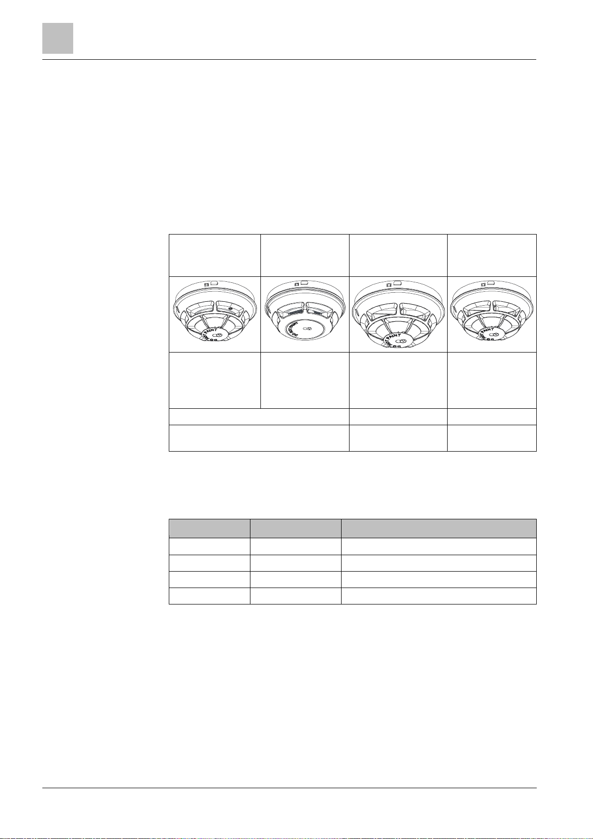
In this document t he following point detectors are r eferred to collectively using the
term 'Automatic fire detectors':
l Multi-sensor fire detector (collective) OH110
l Smoke detector (collective) OP110
l Heat detector (collective, differential) HI110
l Heat detector (collective, static) HI112
Multi- se nsor fire
detector
OH110
Can be used on
conventional detector
lines and collective
detector lines
2 parameter sets 1 parameter set 2 parameter sets
Detection behavior can be selected
Smoke detector
Can be used on
conventional
detector lines and
collective detector
lines
3.1.1 Details for ord ering
Type Order no. Designation
OP110
Heat detector
(collective, differential)
HI110
Can be used on
conventional detector
lines and collective
detector lines
Detection behavior
cannot be selected
Heat detector
(collective, static)
HI112
Can be used on
conventional
detector lines and
collective detector
lines.
Detection behavior
can be selected
OH110 S54372-F11-A1 Multi-sensor fire detector (collective)
OP110 S54372-F4-A1 Smoke detector (collective)
HI110 S54372-F9-A1 Heat detector (collective, dif ferential)
HI112 S54372-F10-A1 Heat detector (collective , static)
14
Building Technologies A6V10316298_e_en_--
Fire Safety 2014-05-21
Page 15
Overview
3.1.2 Product version ES
ES
Depending o
n the product and var ious approvals, the product labels may differ in
The product version ES provides the technical stat us of a device in t erms of
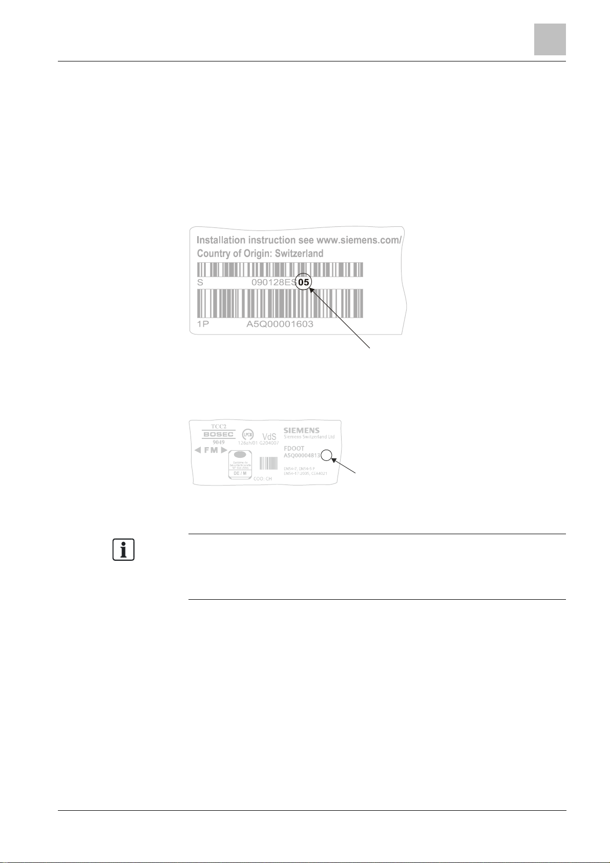
software and hardware. The product version is provided as a two-digit number.
You will find the det ails of your device's product ver sion:
l On the packaging label
l On the product label or the type plate
Product version on the packaging label
Details of the product version can be found directly on the pac kaging label in the
barcode:
Structure and function
3
Example of a packaging label with details of the product version
Product version on the product label and t he type plate
Details of the product version can be found after the device order number:
04
ES
Example of a product label with details of the product version
terms of the informat ion type and layout.
Look for your device' s order number on the product label.
You will find the produc t version after the order number.
Building Technologies A6V10316298_e_en_-Fire Safety 2014-05-21
15
Page 16
Structure and function
Point detector
4
3
3.2 Point detector
3.2.1 Multi-sensor fire detector
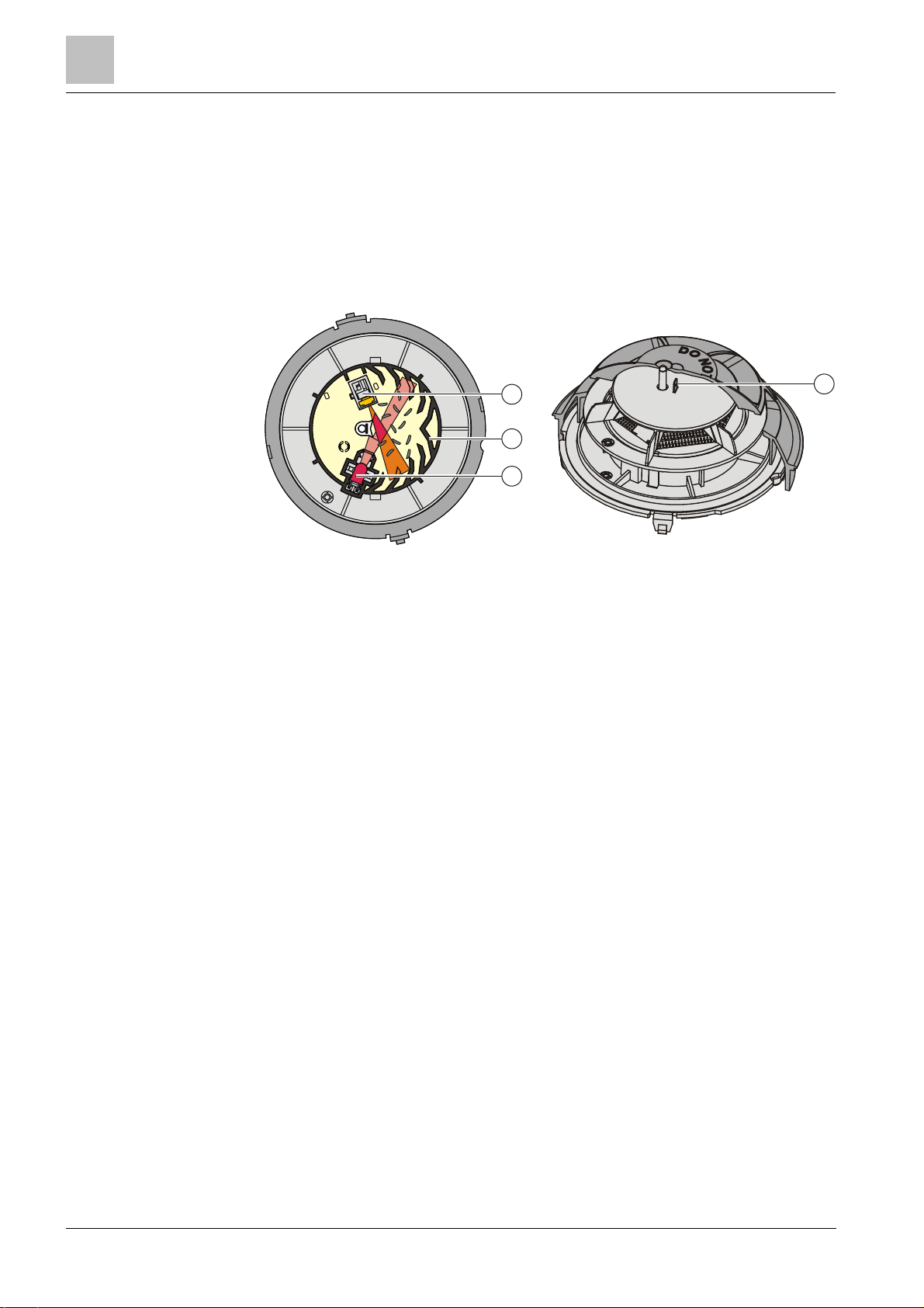
The multi-sensor fire detector OH110 is a multiple-criteria fire detect or with one
optical and one thermal sensor.
Structure and function
3
1
2
1 Labyrinth 3 Optical receiver
2 Optical transmitter 4 Heat sensor
The point detect or has a high-quality opto-electronic measuring chamber. The
measuring chamber contains:
l One optical transmitter
l One optical receiver
l One thermal sensor
The transmitter lights up the smoke particles. The scattered light then hits the
receiver (photodiode) and generates a measurable electric signal.
In addition, t he heat sensor makes it possible to detect fires in cases where no
smoke has been generated.
The combination of optical and thermal sensor signals optim izes detection
reliability with the following benefits.
l Early detection of all types of fire, whether they generate light or dark smoke, or
no smoke at all.
l The fire detector can be operated at a lower sensitivity level, thus achieving
improved immunity against false alarms which may be caused by c old
aerosols. In t he event of an open fire, the smoke sensitivity level is r aised by an
increase in temperature which makes rapidly burning f ires easier to detect.
The multi-sensor fire detector OH110 has two parameter sets: 'Robust' and
'Sensitive'.
16
Building Technologies A6V10316298_e_en_--
Fire Safety 2014-05-21
See also
2 Mult i-sensor fire detector [➙ 29]
Page 17
Point detector
3.2.2 Smoke detector
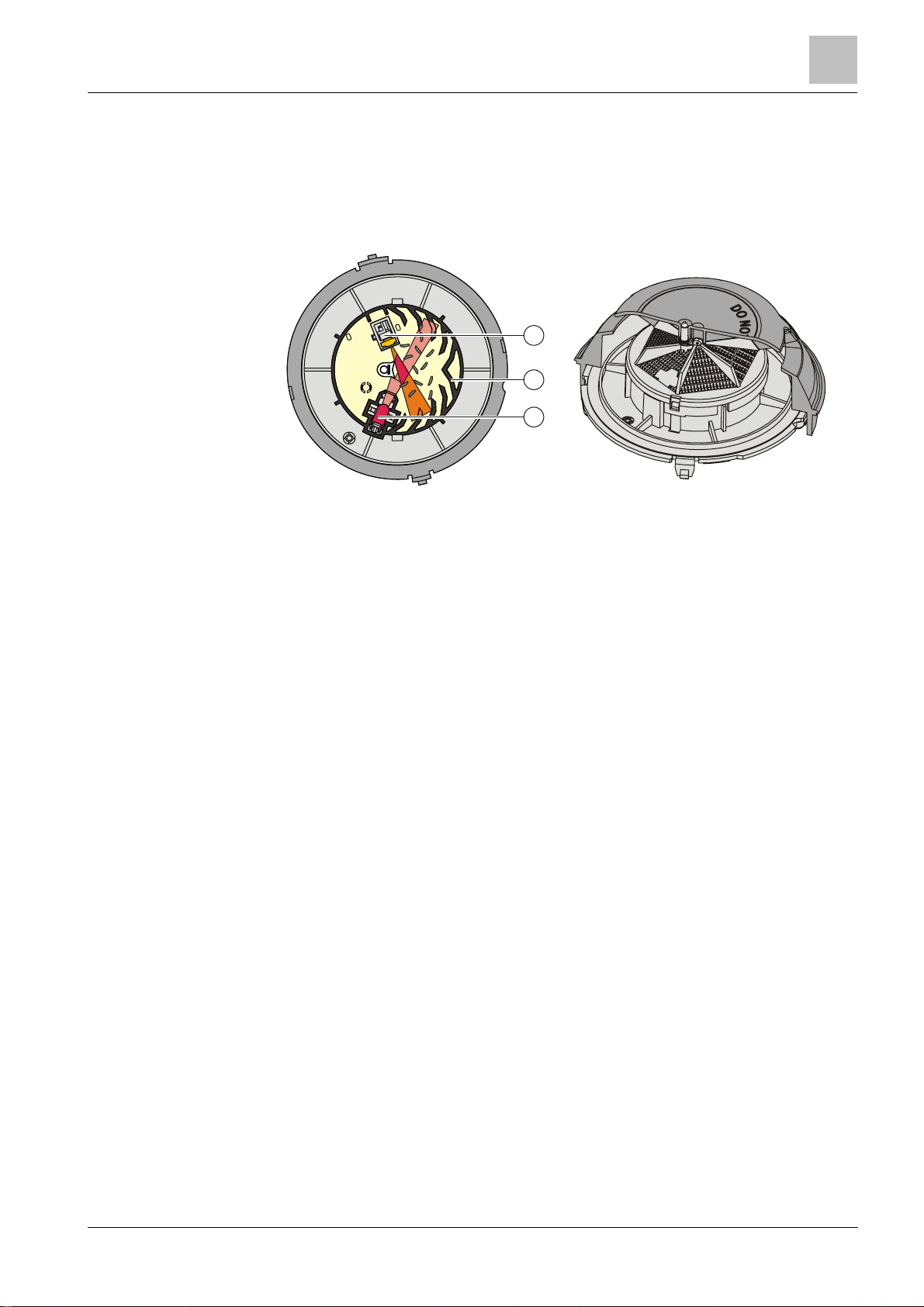
The wide-spectrum smoke detector OP110 is an optical smoke det ector with one
optical sensor.
Structure and function
Structure and function
3
1
2
3
Labyrinth 3 Optical receiver
1
2
Optical transmitter
The wide-spectrum smoke detector has the same measuring cham ber as the multisensor fire detector.
The point detector has two parameter sets: 'Standard' and 'Sensitive'.
See also
2 Smoke detector [➙ 31]
17
Building Technologies A6V10316298_e_en_-Fire Safety 2014-05-21
Page 18
Structure and function
Point detector
1
3
3.2.3 Heat detector
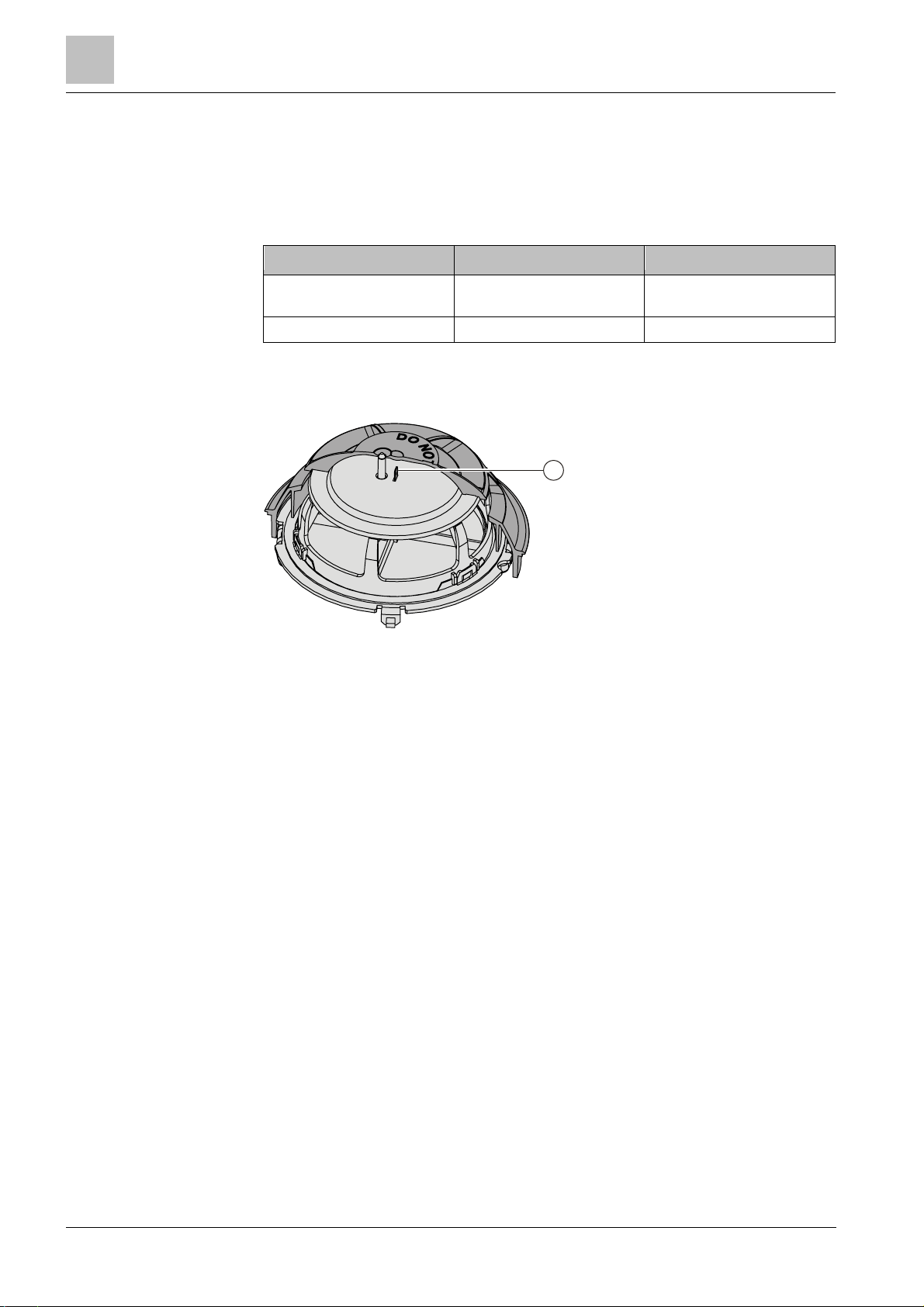
The heat detectors HI110 and HI112 are pure heat detectors with one thermal
sensor.
The following table indicates the most important differences between the two heat
detectors.
Parameter HI110 HI112
Alarm activation by: l Temperature increase
Number of parameter sets 1 2
l Reaching the maximum
temperature
Structure and function
1 Heat sensor
The heat detect or HI110 has one parameter set: 'A1R' (differential).
The heat detector HI112 has two parameter sets 'A2S' (static) and 'B'.
See also
2 Heat detector [➙ 32]
18
Building Technologies A6V10316298_e_en_--
Fire Safety 2014-05-21
Page 19

Function
3.3 Function
Point detector
Detector base
Detector base
Colo
r
Flashing frequency
Meaning
3.3.1 Parameter sets
The detection behavior of the detectors is influenced by the parameter sets, so that
it can be specifically adjusted to the fire phenomena and environment al conditions
to be expected in the envir onment to be monitored.
All parameter sets are programmed in the detectors. To select the parameter set
used, insert t he point det ector into a certain detector base.
The table below illustrates the dependency between t he point det ector's parameter
sets and the detector bases used.
Structure and function
3
used
OH110 'Sensitive' 'Robust'
OP110 'Standard' 'Sensitive'
HI110 'A1R'
HI112 'A2S' 'B'
3.3.2 Diagnosis levels
The point detector monitors most of its functions it self. In particular it monitors the
correct funct ioning of the microcontroller, temperature sensors, light emitter and
light receiver.
If there is a fault, the point detector's internal alarm indicator flashes:
Yellow One flash every 10 s Fault
DB110 or DB110D
DB110R or DB110RD
Building Technologies A6V10316298_e_en_-Fire Safety 2014-05-21
19
Page 20

Structure and function
Function
Color
Parameter set
Flashing frequency
Meaning
Color
Parameter set
Flashing frequency
Meaning
3
3.3.3 Internal alarm indicator
The point detectors have an internal alarm indicat or. The internal alarm indicator
shows the point detector's operating status.
When the point detector is in normal operation, the internal alarm indic ator does
not light up or flash.
The meaning of the int ernal alarm indicator's flash signals is explained in the tables
below.
Multi-sensor fire detector OH110
Red 'Robust' and 'Sensitive' One flash every 1 s Alarm
Yellow 'Robust' and 'Sensitive' One flash every 10 s Fault
Green 'Robust' During the first thr ee minutes of
operation:
Three flashes ever y 10 s
l Reduced response time
for testing after the
detector line is started up
or reset
l No fault
l Operation with 'Robust'
parameter set
From the 4th…15th minute of
operation:
Two flashes every 5 s
Green 'Sensitive' During the first 15 minutes of
operation:
One flash every 5 s
l No fault
l Operation with 'Robust'
parameter set
l No fault
l Operation with 'Sensitive'
parameter set
Smoke detector OP110
Red 'Standard' and 'Sensitive' One flash every 1 s Alarm
Yellow 'Standard' and 'Sensitive' One flash every 10 s Fault
Green 'Standard' During the first 15 minutes of
Green 'Sensitive' During the first 15 minutes of
20
Building Technologies A6V10316298_e_en_--
Fire Safety 2014-05-21
operation:
One flash every 5 s
operation:
Two flashes every 5 s
l No fault
l Operation with 'Standard'
parameter set
l No fault
l Operation with 'Sensitive'
parameter set
Page 21

Structure and function
Function
Color
Parameter set
Flashing frequency
Meaning
Color
Parameter set
Flashing frequency
Meaning
Once the detector line has been started up or reset, the smoke detector OH110
Heat detector HI110
Red 'A1R' One flash every 1 s Alarm
Yellow 'A1R' One flash every 10 s Fault
3
Green 'A1R' During the first 15 minut es of
operation:
One flash every 5 s
l No fault
l Operation with 'A1R'
parameter set
Heat detector HI112
Red 'A2S' and 'B' One flash every 1 s Alarm
Yellow 'A2S' and 'B' One flash every 10 s Fault
Green 'A2S' During t he first 15 minutes of
operation:
One flash every 5 s
Green 'B' During the first 15 minutes of
operation:
Two flashes every 5 s
See also
2 Testing the point detector [ ➙ 50]
l No fault
l Operation with 'A2S'
parameter set
l No fault
l Operation with 'B'
parameter set
3.3.4 Connection for external alarm indicators
A maximum of two ext ernal alarm indicators can be connected to each point
detector.
See also
2 Connection diagram [➙ 48]
3.3.5 Test mode
Optical detectors can be tested with the test gas REF8 or REF8-S. Heat detectors
can be tested with a hot air fan.
has a reduced response time in the 'Robust' parameter set for a period of
3 minutes. It is possible to test the point detector with test gas during this period.
Simplified test readiness of the point detector is indicated by the green LED
flashing three times every 10 s.
See also
2 Testing the point detector [ ➙ 50]
2 Internal alarm indicator [➙ 20]
Building Technologies A6V10316298_e_en_-Fire Safety 2014-05-21
21
Page 22
Structure and function
Mechanical setup
3
3.4 Mechanical setup
One of the following devices is required to install a point detector:
l Detector base (collective) DB110
l Detector base (collective) DB110D
l Detector base (collective) DB110R
l Detector base (collective) DB110RD
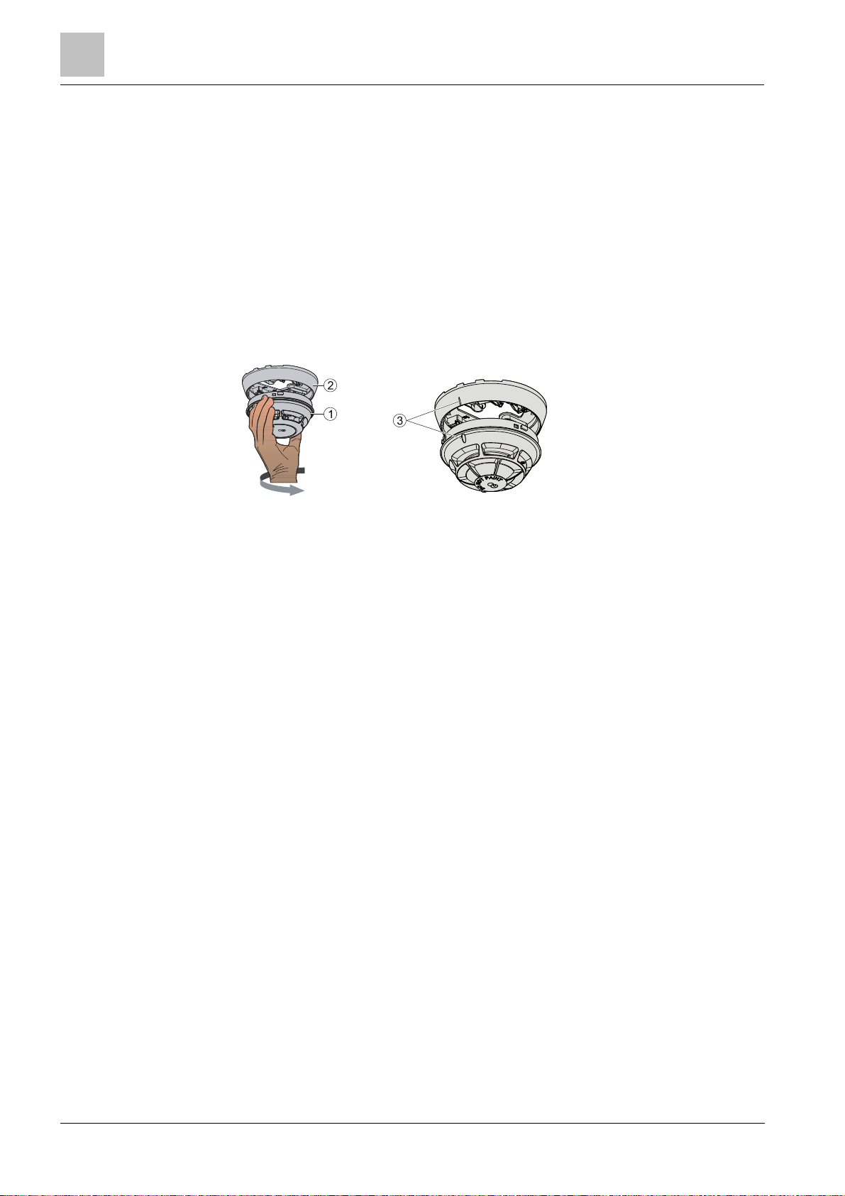
Once the detector bas e (2) has been installed, the point detect or (1) is easily
turned by hand or with the detector exchanger DX791 in the base. You must be
able to hear and feel t he point detector snap into place and the marks (3) on the
point detector and the detector base must line up.
1 Point detector 3 Marks
2
Detector base
Properties
l Quick installation and secure contact
l T he centered alarm indicator makes an alignment of t he detector base
superfluous
l Space for up to 4 auxiliary terminals
Accessories are available for a variety of different applications and can be
combined to suit t he particular application in question.
See also
2 Accessories [➙ 23]
22
Building Technologies A6V10316298_e_en_--
Fire Safety 2014-05-21
Page 23
Accessories
3.5 Accessories
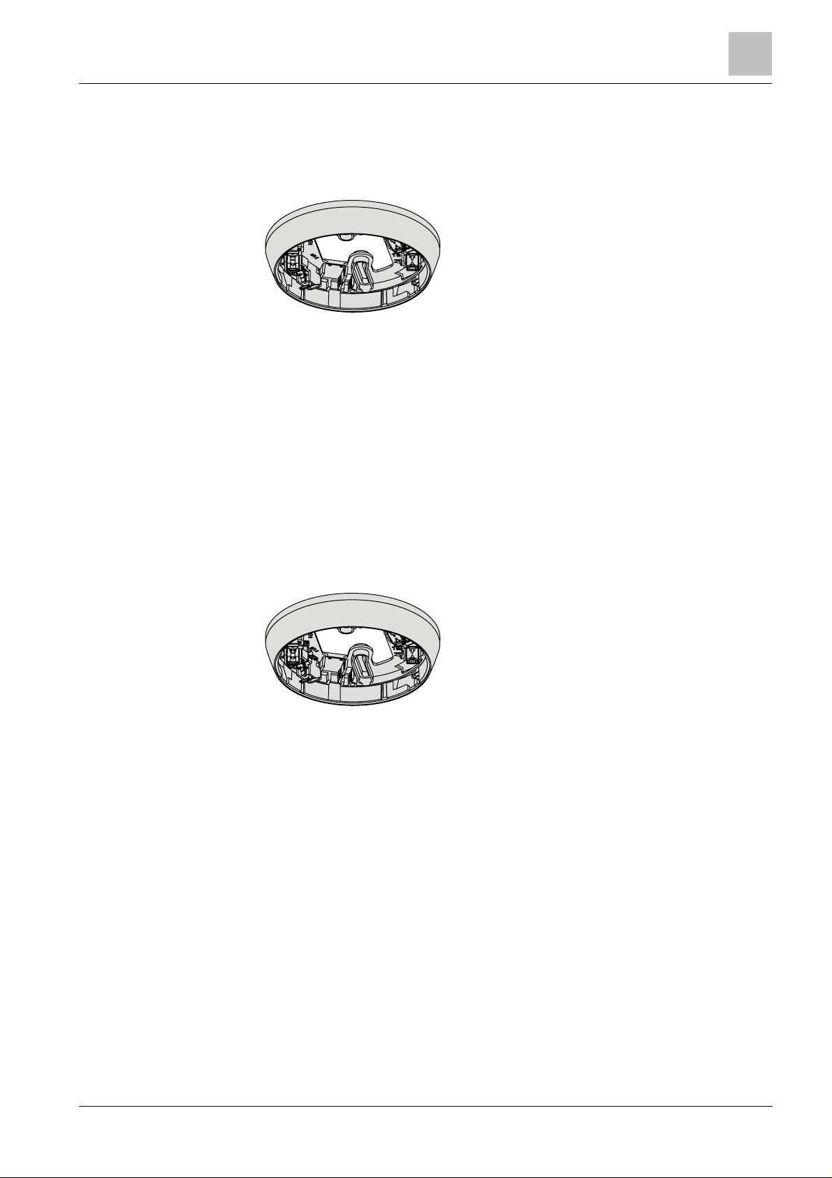
3.5.1 Detector base (collective) DB110
l For the installation of point detectors
l The detector line is interrupted if the point detector
is not used
l Selects the default parameter set in the point
detector used
l For the recess-mounted cable entry
l For the surface-mounted cable entry, up to 8 mm
cable diameter
l Compatible with:
– Multi-sensor fire detector OH110
– Smoke detector OP110
– Heat detector HI110
– Heat detector HI112
l Order no.: S54372-F5-A1
Structure and function
3
See also
2 Detector base (collective) DB110 / DB110x / DB110xx
[➙ 35]
3.5.2 Detector base (collective) DB110D
l For the installation of point detectors
l Built-in diode (for BS 5839, part 1)
l If a point detector is not used, the diode fit ted does
not interrupt the detector line
l Selects the default parameter set in the point
detector used
l For the recess-mounted cable entry
l For the surface-mounted cable entry, up to 8 mm
cable diameter
l Compatible with:
– Multi-sensor fire detector OH110
– Smoke detector OP110
– Heat detector HI110
– Heat detector HI112
l Order no.: S54372-F6-A1
See also
2 Detector base (collective) DB110 / DB110x / DB110xx
[➙ 35]
23
Building Technologies A6V10316298_e_en_-Fire Safety 2014-05-21
Page 24
Structure and function
Accessories
3
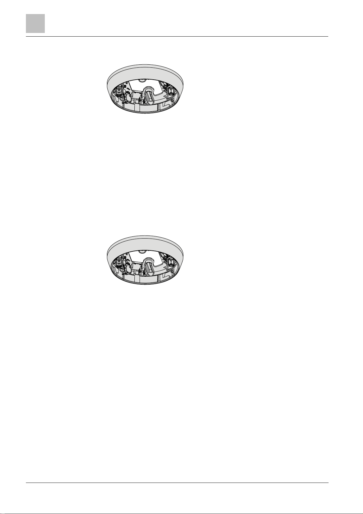
3.5.3 Detector base (collective) DB110R
l For the installation of point detectors
l The detector line is interrupted if the point detector
is not used
l An integrated resistor selects the second parameter
set in the point detector
l For the recess-mounted cable entry
l For the surface-mounted cable entry, up to 8 mm
cable diameter
l Compatible with:
– Multi-sensor fire detector OH110
– Smoke detector OP110
– Heat detector HI110
– Heat detector HI112
l Order no.: S54372-F7-A1
See also
2 Detector base (collective) DB110 / DB110x / DB110xx
[➙ 35]
3.5.4 Detector base (collective) DB110RD
l For the installation of point detectors
l Built-in diode (for BS 5839, part 1)
l If a point detector is not used, the diode fit ted does
not interrupt the detector line
l An integrated resistor selects the second parameter
set in the point detector
l For the recess-mounted cable entry
l For the surface-mounted cable entry, up to 8 mm
cable diameter
l Compatible with:
– Multi-sensor fire detector OH110
– Smoke detector OP110
– Heat detector HI110
– Heat detector HI112
l Order no.: S54372-F8-A1
See also
2 Detector base (collective) DB110 / DB110x / DB110xx
[➙ 35]
24
Building Technologies A6V10316298_e_en_--
Fire Safety 2014-05-21
Page 25
Accessories
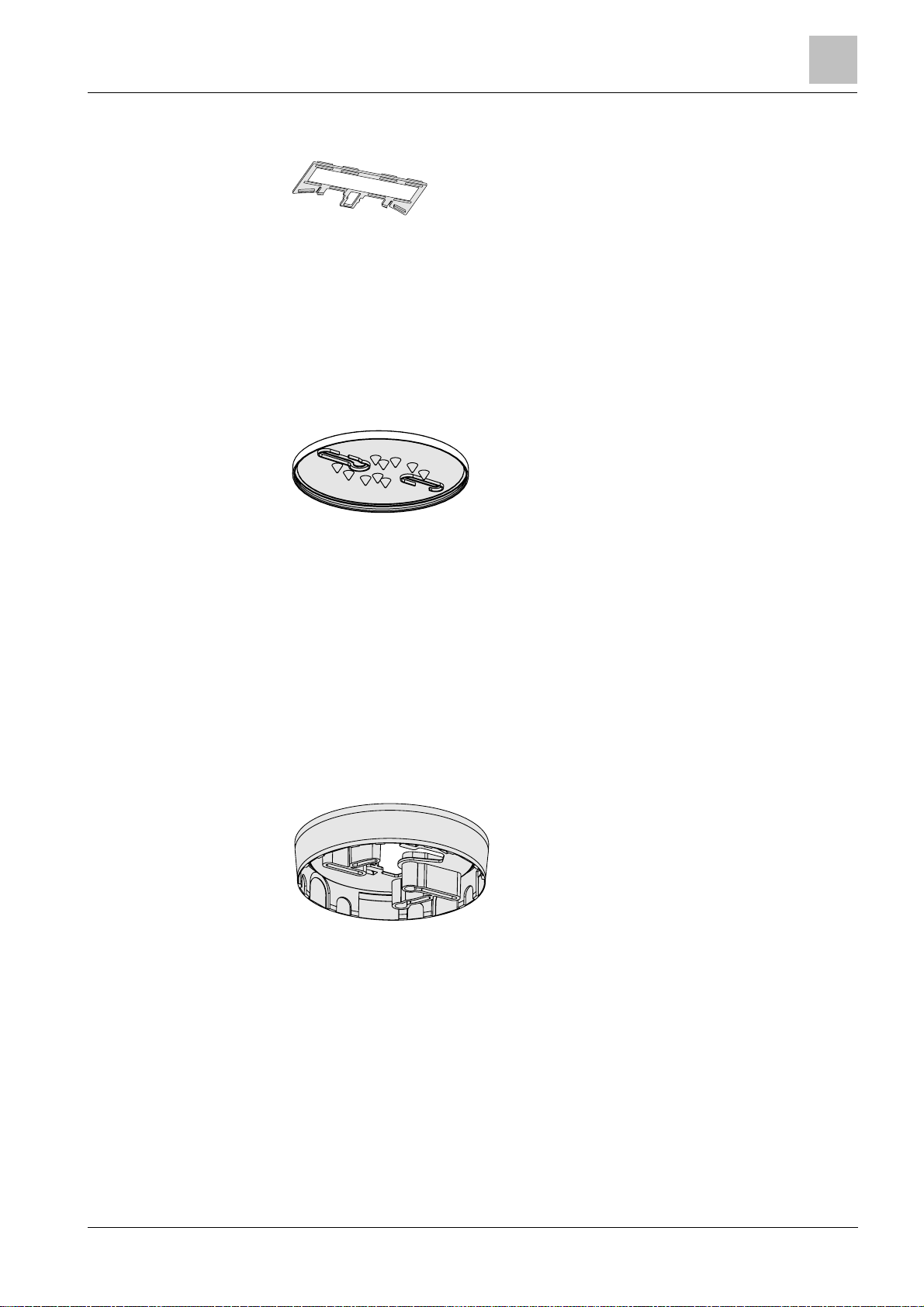
3.5.5 Designation plate FDBZ291
l To identify the location
l Compatible with:
– Detector base (collective) DB110
– Detector base (collective) DB110x
– Detector base (collective) DB110xx
l Order no. A5Q00002621
See also
2 Designat ion plate FDBZ291 [➙ 42]
3.5.6 Detector base seal RS720
l For installation in wet rooms
l Protection category IP42
l Compatible with:
– Detector base (collective) DB110
– Detector base (collective) DB110x
– Detector base (collective) DB110xx
– Detector base FDB271
– Detector base FDB271-R
l Not compatible with:
– Designation plate FDBZ291
l Order no.: S54319-F8-A1
Structure and function
3
See also
2 Detector base seal RS720 [➙ 36]
3.5.7 Base attachme nt BA720
l There are several potential break-out points in the
l For the recess-mounted cable entry
l Permanent connection and joint installation with
l Compatible with:
l Order no.: S54319-F20-A1
See also
2 Bas e attachment BA720 [➙ 37]
base attachment for surface-mounted cable entry
detector base
– Detector base (collective) DB110xx
25
Building Technologies A6V10316298_e_en_-Fire Safety 2014-05-21
Page 26
Structure and function
Accessories
3
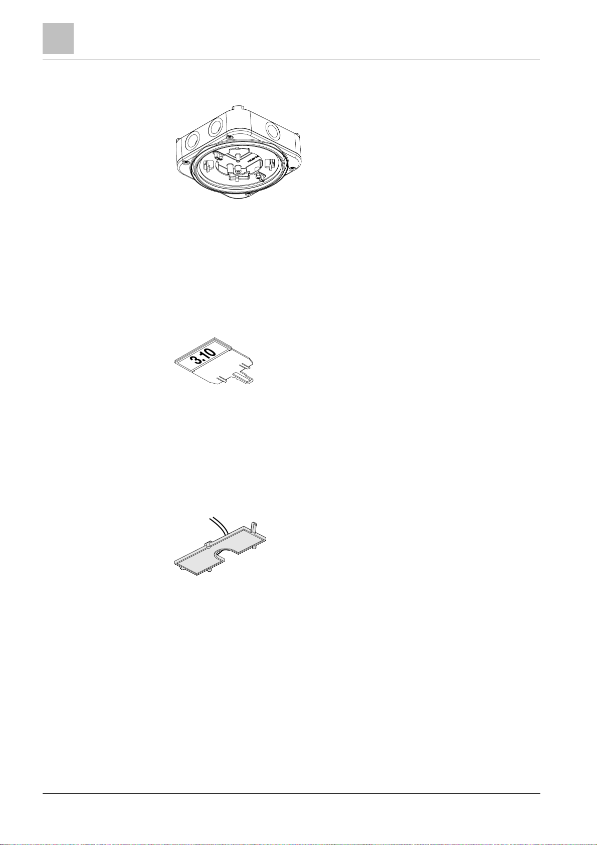
3.5.8 Base attachment wet BA721
l For installation in humid, wet environments and if
the detector heating unit is used
l Protection category achievable: IP44
l Six break-out points for M20 x 1.5 metal cable
glands
l Compatible with:
– Detector base DB72x/DB110xx/DB721D
– Detector heating unit FDBH291
– Designation plate DBZ1193A
– M20 x 1.5 metal cable gland
l Order no.: S54319-F29-A1
See also
2 Base attachment wet BA721 [➙ 39]
3.5.9 Designation plate DBZ1193A
l To identify the location
l Compatible with:
– Base attachment wet FDB295/BA721
– Base attachment, surface-mounted, humid
DBZ1192
– DBW1171 base
– Sounder interbase DBS721
– Sounder interbase with additional optical
indicator DBS729
l Order no.: BPZ:4864330001
3.5.10 Detector heating unit FDBH291
l For operating point detectors in critical ambient
conditions during icy conditions or when there is a
danger of moisture condensation
l Compatible with:
– Addressable detector base
FDB2x1/FDB2x1-AA
– Flat detector base FDB2x2
– Base attachment wet FDB295/BA721
l Order no.: A5Q00004439
26
Building Technologies A6V10316298_e_en_--
Fire Safety 2014-05-21
Page 27

Accessories
3.5.11 Protective cage DBZ1194
l To protect the devices against mechanical damage
l Can only be used in conjunction with the following
l Order no.: BPZ:4677110001
See also
2 Base attachment wet BA721 [➙ 39]
Structure and function
accessories:
– Base attachment wet FDB295
– Base attachment wet BA721
3
3.5.12 EMC-protective cage FDBZ294
l To protect the devices against mechanical damage
and electromagnetic fields
l Must be connected with earth connection
l Can only be used in conjunction with the following
accessories:
– Base attachment humid FDB293
– Base attachment wet FDB295
– Base attachment wet BA721
l Order no.: A5Q00023040
See also
2 Base attachment wet BA721 [➙ 39]
3.5.13 Detector locking device LP720
l For protection against theft
l Compatible with:
– Multi-sensor fire detector (collective) OH110
– Smoke detector (collective) OP110
– Heat detector (differential, collective) HI110
– Heat detector (static, collective) HI112
l Order no.: S54319-F9-A1
See also
2 Detector locking device LP720 [➙ 41]
27
Building Technologies A6V10316298_e_en_-Fire Safety 2014-05-21
Page 28

Structure and function
Accessories
3
3.5.14 Micro terminal DBZ1190-AA
l Auxiliary terminal for connecting cables
l For T-branches of additional cabling e.g. for
detector heating units, sounder base, external
alarm indicators etc.
l For wire diameters of 0.28…0.5 mm
l 4-pin
l Order no.: BPZ:4677080001
See also
2 Auxiliary terminals DBZ1190-AA/-AB [➙ 43]
3.5.15 Connecti on terminal D BZ1190-AB
l Auxiliary terminal for connecting cables
l For T-branches of additional cabling e.g. for cable
shielding, detector heating units, sounder base,
external alarm indicators etc.
l For wire diameters of 1…2.5 mm²
l 3 poles
l Order no.: BPZ:4942340001
2
See also
2 Auxiliary terminals DBZ1190-AA/-AB [➙ 43]
28
Building Technologies A6V10316298_e_en_--
Fire Safety 2014-05-21
Page 29

Compatibility
4 Planning
The parameter set 'Robus t' is automatically set if the point detector is installed in
The parameter s et 'S ensitive' is automatically set if the point detector is inst al
led
4.1 Compatibility
Compatible with cont rol panels which support collective operation or conventional
operation on the detector line.
You will find details in the 'List of compatibility'.
4.2 Multi-sensor fire detector
Like all optical smok e detectors, the multi-sensor fire detector OH110 is able to
detect slow-burning fires that generate smoke.
However, when compared to standard optical smoke detectors, the multi-sensor
fire detector OH110 also offers improved res ponse behavior in the event of open
fires and increased resistance to misleading sources of false alarms.
The multi-sensor fire detector OH110 has two selectable parameter sets.
Planning
4
4.2.1 Parameter sets
Robust:
The parameter s et 'Robus t' offers improved resistance to false alarms in areas
where misleading sources, such as cigarette smoke or exhaust fumes, may cause
these to be triggered.
a detector base DB110R or DB110RD.
Sensitive:
This parameter s et is partic ularly suitable for areas where few misleading sources
of false alarms are present, when priority is given to detecting open f ires as early
as possible.
in a detector base DB110 or DB110D.
Building Technologies A6V10316298_e_en_-Fire Safety 2014-05-21
29
Page 30

Planning
Multi-sensor fire detector
All parameter set s meet the criteri
a of standard EN
54-7.
4
Name Thermal
4.2.2 Specifications
The table below shows the properties of the parameter sets for the multi-sensor fire
detector OH110:
Typ. response
time
[s] [%/m] [°C] ∆T [K] [°C]
Sensitive 10 2,5 60 25
Robust 35
3
Sensitivity Static activation
temperature
3,5 60 25
1
Applicable with fast temperature increases >10 K/min.
2
Between 1 K/min and 10 K/min, this value increases by a few degrees.
3
The response time is reduced in the first three minutes following the detector
Differential activation
temperature
line being started up or reset. The reduced response time enables the point
detector to be tested with test gas.
1
2
2
Differential activation
possible from:
10
10
30
Building Technologies A6V10316298_e_en_--
Fire Safety 2014-05-21
Page 31

Smoke de
tector
4.3 Smoke detector
The parameter s et 'Standar d' is automatically set if the point detector is inst alled
The parameter s et 'S ensitive' is automatically set if the point detector is inst all
ed
All parameter set s meet t
he criteria of standard EN
54-7.
The optical smok e detector OP110 demonstrates quick response behavior in the
event of slow-burning fires that generat e smoke. It is extremely well suited to
general-purpose applications.
The smoke det ector OP110 has two selectable parameter sets.
4.3.1 Parameter sets
Standard:
For standard applications, such as in corridors, bedrooms, offices, and living
rooms.
in a detector base DB110 or DB110D.
Sensitive:
For areas wit h few misleading sources of false alarms, such as cigarette smoke,
exhaust fumes, and steam.
Planning
4
in a detector base DB110R or DB110RD.
4.3.2 Specifications
The table below shows t he properties of the parameter set for the smoke detector
OP110:
Name Response time [s] Sensitivity [%/m]
Standard 10 2,3
Sensitive 10 1,8
Building Technologies A6V10316298_e_en_-Fire Safety 2014-05-21
31
Page 32

4
Heat detector
Planning
4.4 Heat detector
The heat detector HI110 can recognize sharp increases in temperature and is
suitable for areas with a stable ambient temperature.
The heat detect or HI112 responds when the temperature exceeds a preset
threshold value.
Heat detectors are used in environments where misleading sources of false alarms
are present and where, if smoke detectors were to be used, an unacceptable
number of false alarms would be triggered.
4.4.1 Parameter sets
The heat detectors HI110 and HI112 have the following param eter sets:
HI110
l 'A1R'
HI112
l 'A2S'
l 'B'
Explanation of designation 'A'
l 'A' parameter sets should be applied at an ambient temperature of
approximately 25 ℃. However, they can be applied at temperatures up to 50
°C. The static response temperature is 60 °C.
Explanation of designation 'B'
l 'B' parameter sets should be applied at an ambient temperature of
approximately 40 ℃. However, they can be applied at temperatures up to 65
°C. The static response temperature is 80°C.
Explanation of designations 'R' and 'S'
l I n comparison to the 'S' parameter sets, 'R' parameter sets also trigger alarms
in the event of a temperature increase (e.g., from 20° C to 50 °C within a few
minutes).
32
Building Technologies A6V10316298_e_en_--
Fire Safety 2014-05-21
Page 33

Heat detector
4.4.2 Specifications
All parameter set s meet the criteria of standard EN
54-5.
The table below shows t he properties of the parameter sets for the heat detectors
HI110 and HI112:
Planning
4
Name Operating temperature
typ. / max.
[°C] [°C] ∆T [K] [°C]
'A1R' 25 / 5 0 60 25
'A2S'
60 ℃ maximum
'B' 40 / 65 80 – –
25 / 50 65 – –
1
Applic able with slow temperature increases <1 K/min.
2
Applic able with fast temperature increases >10 K/min.
3
Between 1 K/min and 10 K/min, this value increases by a few degrees.
Static activation
temperature
1
Differential activation
temperature
2
3
Differential activation
possible from:
10
Building Technologies A6V10316298_e_en_-Fire Safety 2014-05-21
33
Page 34
Mounting / Installation
Required space
5
5 Mounting / Installation
5.1 Required space
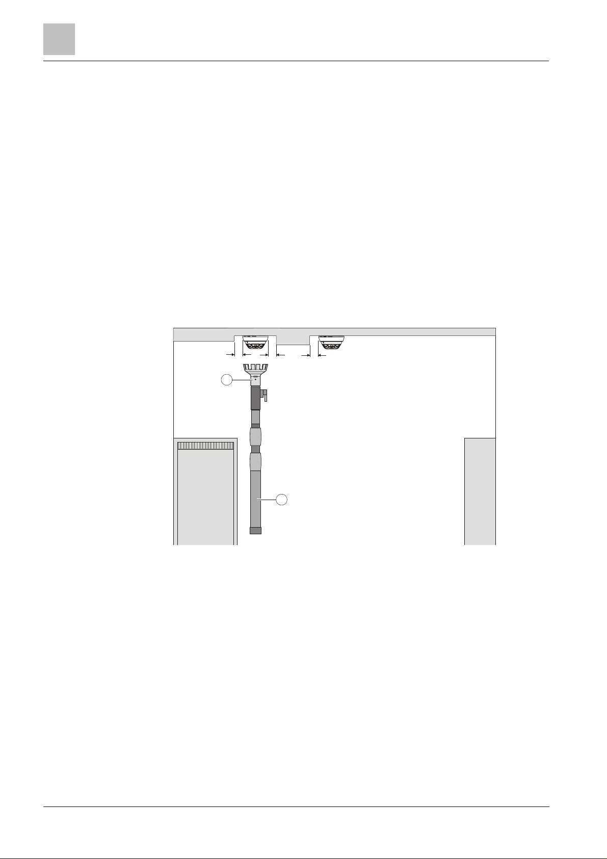
l When the point detector is inserted, the detector base is placed under stress by
compression, tension, and torsion. The fastening method must, therefore, be
designed accordingly.
l Detect or bases must be placed flat on the ceiling.
l Avoid mounting on steps, concrete ribs, etc.
l Install the detector base directly on the recessed box or a level surface.
l If a surface-mounted cable feed is used, there are two possible break-out
points on the detector base for the cable entry. Max. cable diameter: 8 mm.
l The point detector must have at least 2 cm of free space to the side. Only then
can the point detector be removed with the detector exchanger DX791.
l Cont orted detector bases complicate or even impede the insertion of the
detectors with the detector exchanger.
*
1
1
Detector exchanger 2 Telescope or extension rod
*
* = min. 2 cm
2
*
34
Building Technologies A6V10316298_e_en_--
Fire Safety 2014-05-21
Page 35
Detector base (collective) DB110 / DB110x / DB110xx
5.2 Detector base (collective)
Incorrect laying of cables
●
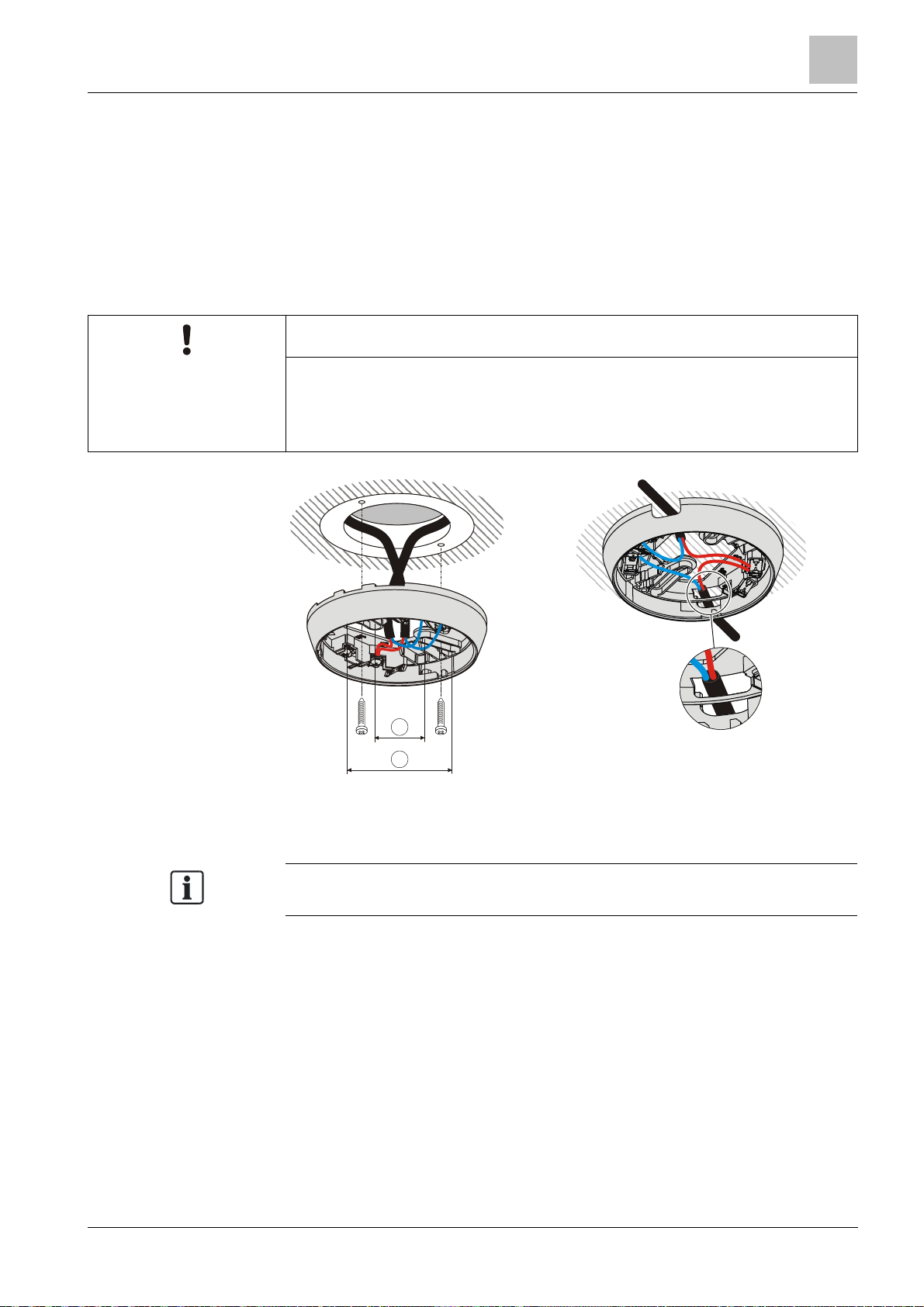
The bare length of the cables is approximately
8…10
mm.
1
2
Use the detector bases DB110D and DB110RD if you are installing a fire
DB110 / DB110x / DB110xx
l Inst all the detector base direc tly on t he ceiling.
l Insert the cables into the detector base. You have the option of using the
following types of line:
– Recess-mounted cable entry
– Sur face-mounted cable entry (cable diameter max. 8 mm)
NOTICE
Damage to cables and diff iculties when installing the point detector
● The cable loops must be placed flat in the base bottom.
Mounting / Installation
5
1 Minimum Ø 40 mm 2 Maximum Ø 90 mm
detection system in accordance with BS 5839, part 1.
35
Building Technologies A6V10316298_e_en_-Fire Safety 2014-05-21
Page 36
Mounting / Installation
Detector base seal RS720
5
5.3 Detector base seal RS720
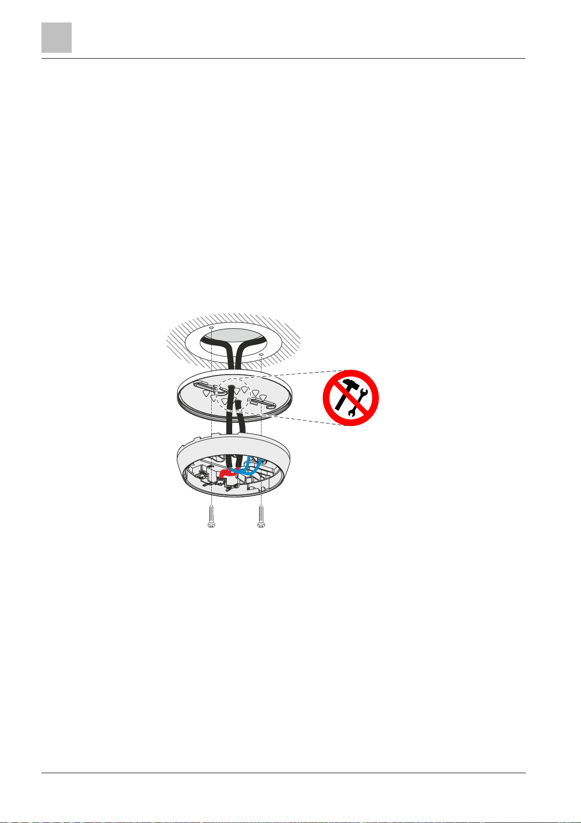
l Use the detector base seal RS720 to install point detectors in wet rooms.
Protection category: IP42.
l Compatible with t he following detector bases:
– Detector base (collective) DB110
– Detector base (collective) DB110R
– Detector base (collective) DB110D
– Detector base (collective) DB110RD
l Only use f or recess-mounted cable ent ry.
Installation
1. NO TICE! Excessively large holes in the detector base seal will impair the
potential I P prot ection category. Do not cut or drill holes in the detector base
seal. Without using a tool, push the lines through t he detector base seal.
2. Fit the det ector base seal RS720 between the ceiling and the detector base.
36
Building Technologies A6V10316298_e_en_--
Fire Safety 2014-05-21
Installing the detector base seal RS720
Page 37
Base attachment BA720
5.4 Base attachment BA720
1
2
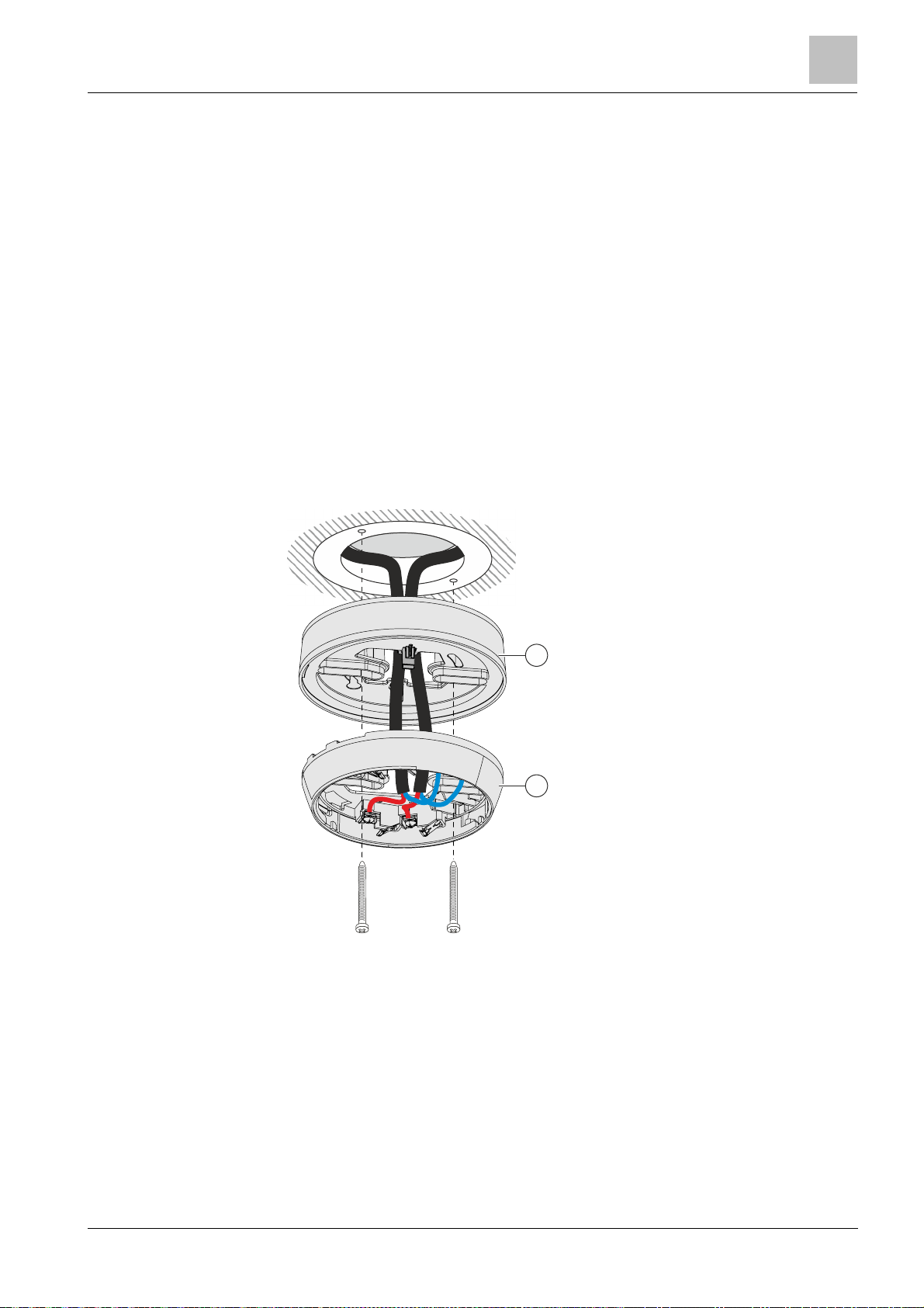
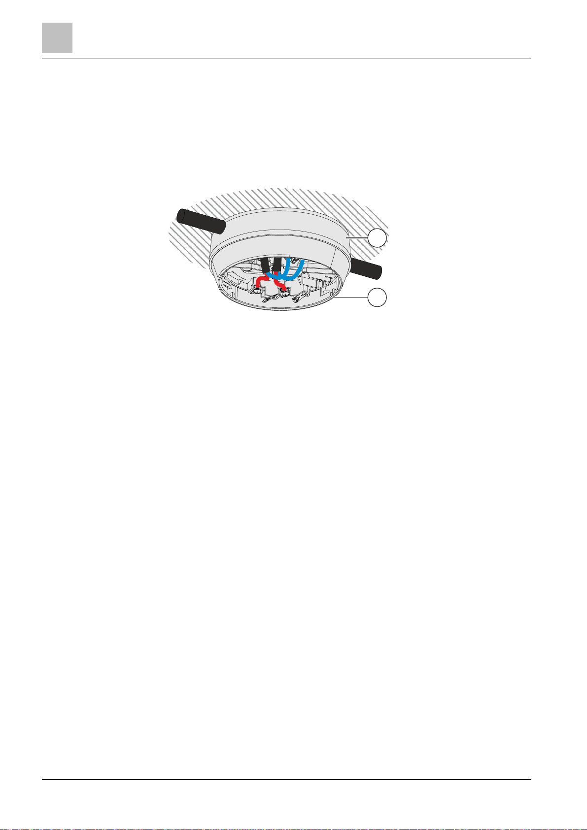
Install the base attachment BA720 if you are using a cable with a diameter >8 mm
for surface-mount ed cable entry.
The base attachment BA720 is attached to the ceiling together with a detector
base.
Compatible with the f ollowing detector bases:
l Detector base (collective) DB110
l Detector base (collective) DB110R
l Detector base (collective) DB110D
l Detector base (collective) DB110RD
Installation for recess-mounted cable entry:
1. Insert the cables into the base attachment BA720 (1).
2. Inst all the base attachment BA720 (1) on the ceiling together with a detector
base (2).
3. Connect t he cables in the detector base (2).
Mounting / Installation
5
Building Technologies A6V10316298_e_en_-Fire Safety 2014-05-21
Recess-mounted cable entry with base attachment BA720
Base attachment BA720 2 Detector base DB110xx
1
37
Page 38
Mounting / Installation
Base attachment BA720
1
2
5
Installation for surface-mounted cable entry:
1. Break out the areas required for cable ent ry in the base attachment BA720 (1).
2. Insert the cables into the base attachment BA720 (1) through the broken-out
areas.
3. Inst all the base attachment BA720 (1) on the ceiling together with a detector
base (2).
4. Connect t he cables in the detector base (2).
Surface-mounted cable entry with base attachment BA720
Base attachment BA720 2 Detector base DB110xx
1
38
Building Technologies A6V10316298_e_en_--
Fire Safety 2014-05-21
Page 39
Base attachment wet BA721
5.5 Base attachment wet BA721
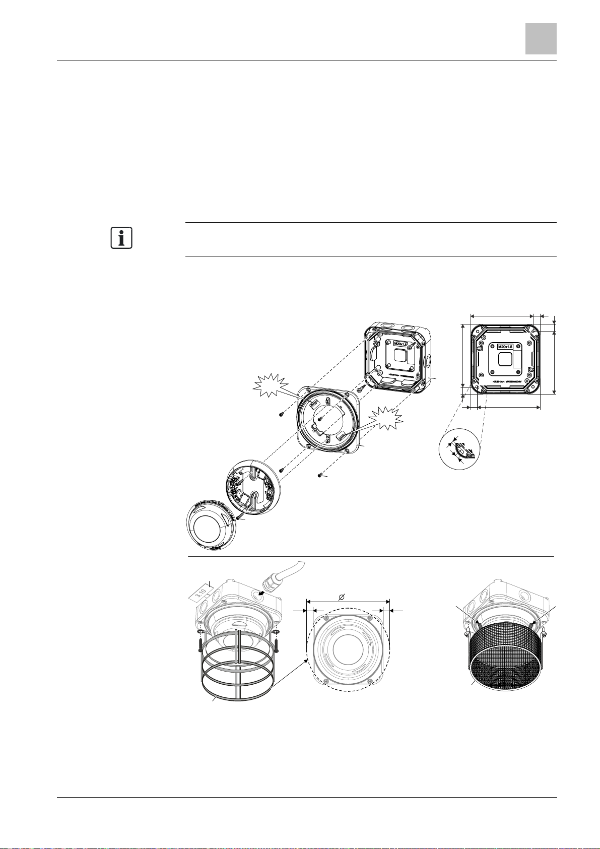
Note the dimensions of the protective cages (Fig.
3)
before installing base
122
122
13
13122
122
13
13
13
Fig. 1
Fig. 2
Fig. 3
Fig. 4
A
A
DBZ1194
1x
1x
4
.
5
7
.
5
A
Click
Base attachment wet BA721 is for surface-mounted feed lines in humid and cold
environments. The cables are inserted using M20 x 1.5 metal cable glands (Fig. 3).
Protective c ages DBZ1194/FDBZ294 can be installed on 'base attachment wet
BA721'.
l Prot ective cage DBZ1194 (Fig. 3) protects the detector against mechanical
damage.
l EMC-pr otective cage FDBZ294 (Fig. 4) protects the detector against
mechanical damage and electromagnetic fields.
attachment wet BA721!
You will find information on connecting detector heating unit FDBH291 in the
'Connection of the detector heating unit' chapter.
Mounting / Installation
5
Click
DB110xx
DB721
DB721D
2x
DBZ1193A
4x
160
13
Installation and removal of protective cages and designation plates on base attachment wet
BA721
Building Technologies A6V10316298_e_en_-Fire Safety 2014-05-21
FDBZ294
39
Page 40

Mounting / Installation
Base attachment wet BA721
Danger of falling
●
Only use detector exchanger DX791 as an installation to
ol.
5
Fig. 1 Installation of base attachment wet BA721
l Installation on back box on substruct ure (2 screws)
l Installati on of housing cover on back box ( 4 screws)
l Ins tallation of det ector bas e (2 screws)
Fig. 2 Master gauge for recesses
Fig. 3 Installation of protectiv e cage DBZ1194, M20 x 1.5 metal cable gland, designation plate
DBZ119 3A
Fig. 4 Installation of EMC-protective cage FDBZ294
WARNING
Danger of injury
● When installing, use a secured ladder or work plat form.
Installation (Fig. 1 and Fig. 2)
1. Inst all the M20 x 1.5 metal cable gland(s) in the back box of the base
attachment wet.
2. Fit the back box securely to the substructure with 2 screws (detail A).
3. Screw the housing cover to the back box with the 4 screws.
4. Push the det ector base into base attachment wet BA721.
a You must be able to hear the detector base click into place.
5. Screw t he detector base securely onto base attachment wet BA721 using
2 screws.
Removing the detector base
1. Loosen the t wo screws on the detector base.
2. Disengage the lock with a screwdriver ('click').
3. Remove the detector base from base attachment wet BA721.
See also
2 Detector heating unit FDBH291 [➙ 26]
2 EM C-protective cage FDBZ294 [➙ 27]
2 Protective cage DBZ1194 [➙ 27]
40
Building Technologies A6V10316298_e_en_--
Fire Safety 2014-05-21
Page 41
Detector locking device
LP720
5.6 Detector locking device LP720
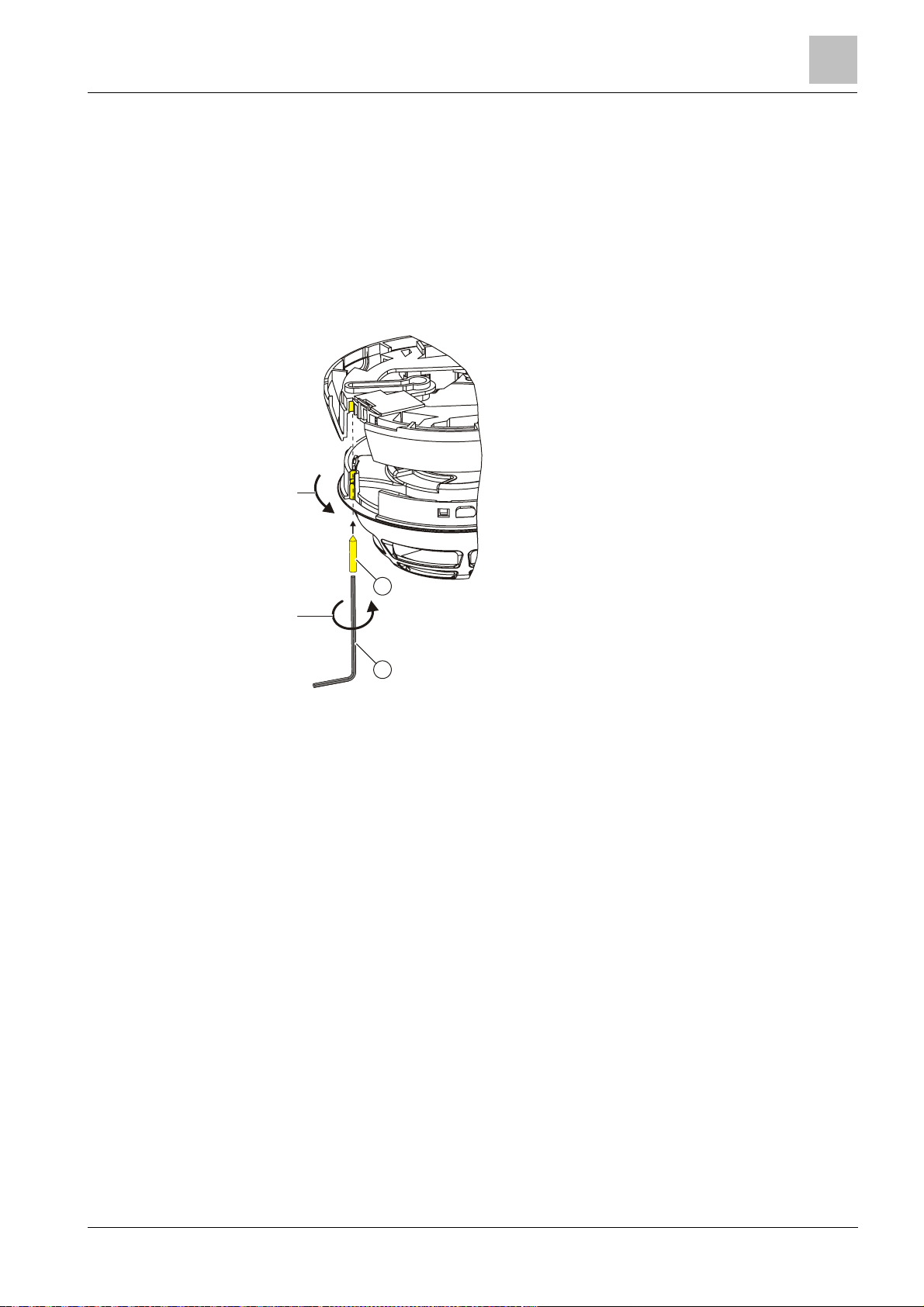
The point detector can be protected against theft with the detector locking device
LP720.
The detector locking devic e LP720 is compatible with
l Detector base (collective) DB110
l Detector base (collective) DB110D
l Detector base (collective) DB110R
l Detector base (collective) DB110 RD
1.
Mounting / Installation
5
A
2.
B
A Grub screw M3 x 12 mm B Hexagonal wrench
1. Insert the detector in the detector base.
2. Insert the hexagonal wrench provided in the bore hole on the detector housing
and tighten the grub screw.
Building Technologies A6V10316298_e_en_-Fire Safety 2014-05-21
41
Page 42

Mounting / Installation
Designation plate FDBZ291
If t
he detector base seal RS720 is being used, it is not possible to install the
5
5.7 Designation plate FDBZ291
1. Label designation plate FDBZ291 with location address of point detector.
2. Attach designation plate FDBZ291 to detector base DB110, DB110x or
DB110xx.
designation plate FDBZ291.
Installation of designation plate FDBZ291
42
Building Technologies A6V10316298_e_en_--
Fire Safety 2014-05-21
Page 43
Cable entry
5.8 Cable entry
Incorrect laying of cables
●
The bare length of the cables is approximately
8…10
mm.
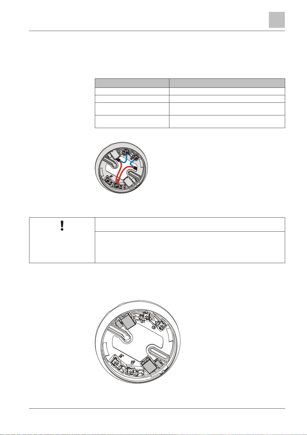
The detector bases DB110, DB110x and DB110xx feature four screw terminals. A
maximum of 2 cables may be connect ed to each screw terminal.
The cable cross section of the screw terminals is 0.2…1.6 mm2.
Termi nal name Connec t io n
1a +Connection for ex ternal alarm indicator
1b +Collective detector line IN and OUT
5 -Collective detector line IN (from the control panel) / -
6 -Collective detector line OUT (from the EOL) / -ex ternal alarm
external alarm indicator
indicator
Mounting / Installation
5
NOTICE
Damage to cables and diff iculties when installing the point detector
● The cable loops must be placed flat in the base bottom.
5.8.1 Auxiliary terminals DBZ1190-AA/-AB
Use the following auxiliary terminals for multiple connections:
l DBZ1190-AB connection terminal 1…2.5 mm²
l DBZ1190-AA micro terminal 0.28…0.5 mm²
Detector base with connection terminals and micro terminals
Building Technologies A6V10316298_e_en_-Fire Safety 2014-05-21
43
Page 44
Mounting / Installation
Detector dust cap
1
2
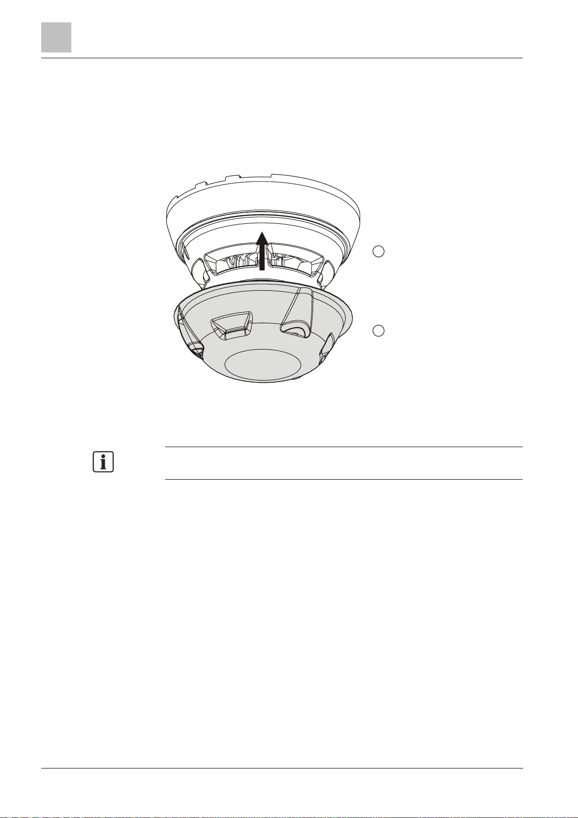
A detector dust cap is included in the scope of supply for the point dete
ctors
5
5.9 Detector dust cap
1. Cover the point detectors OH110 and OP110 with the detector dust cap during
the construction phase. This will protect the point det ector from dust and dirt.
2. Once construction work is complet e, remove the detector dust cap from the
point detector.
1 Point detector 2 Detector dust cap
OH110 and OP110.
44
Building Technologies A6V10316298_e_en_--
Fire Safety 2014-05-21
Page 45
Detector heating unit FDBH291
5.10 Detector heating unit FDBH291
O
ptimum function of the detector heating unit is only guaranteed with base
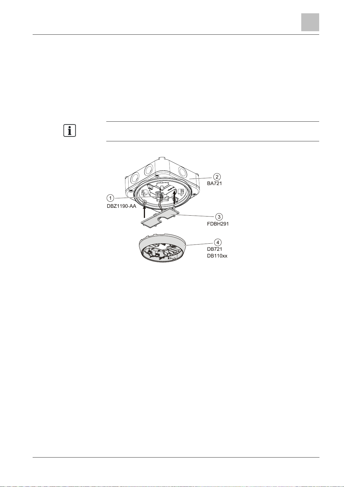
5.10.1 I nstallation of the detecto r heating unit
When the detector is exposed to icing or moisture condensation (e.g., in cooling
rooms, attics, loading ramps), detector heating unit FDBH291 is installed in the
detector base. The detector heating unit increases the detector temperature by
approximately 2 °C over the ambient temperature and thus avoids moisture
condensation on the detector.
attachment wet BA721.
Mounting / Installation
5
Installation of the detector heating unit FDBH291
Micro terminals 3 Detector heating unit
1
2
Base attac h me nt humid 4 Detector bas e
Building Technologies A6V10316298_e_en_-Fire Safety 2014-05-21
45
Page 46
Mounting / Installation
Detector heating unit FDBH291
Risk of icing
●
To ensure smooth operat ion, the detector must be checked regularly for icing.
-
FDBH291
DBZ1190-AA
DB721
DB110xx
DB110xx
5
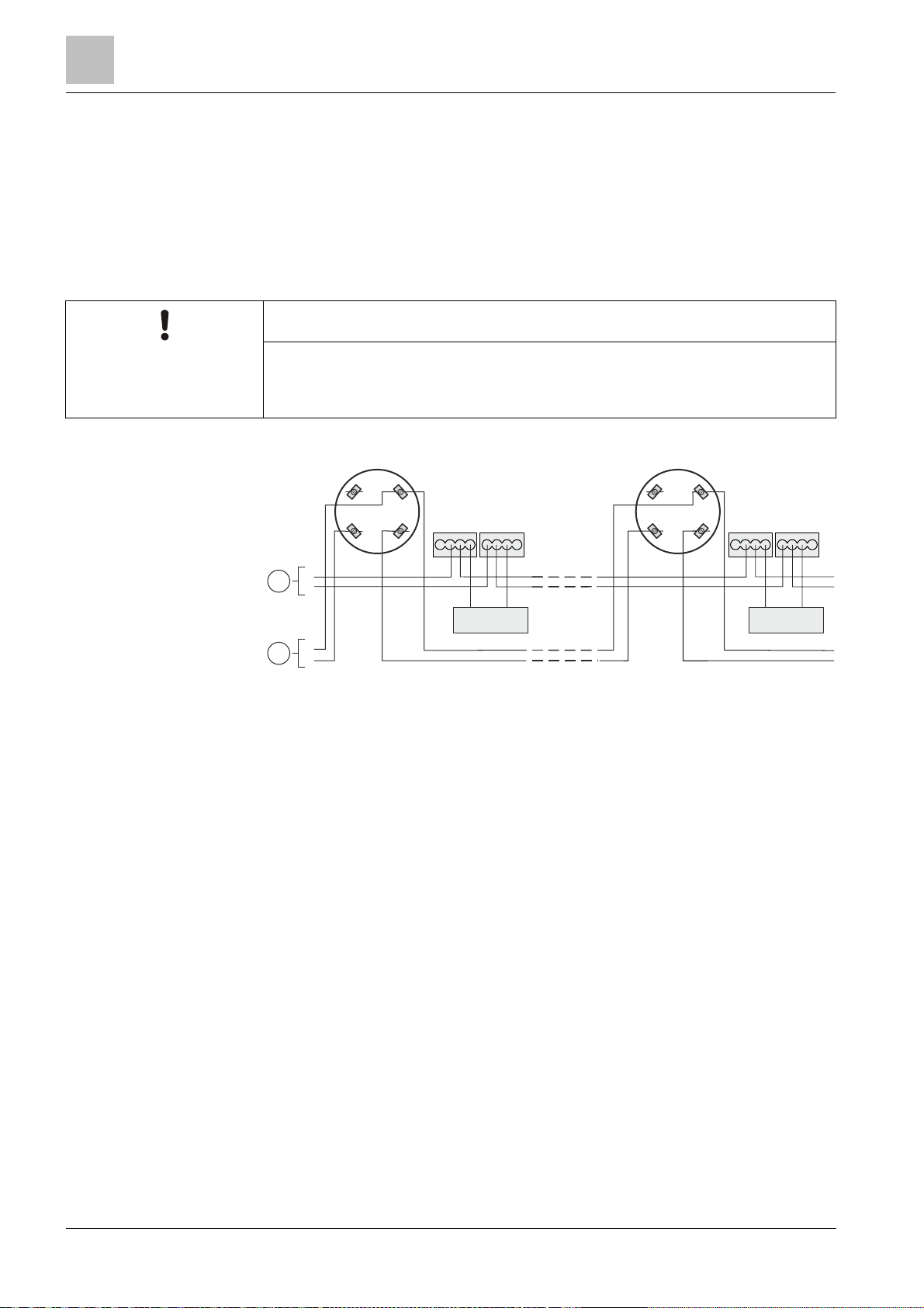
5.10.2 Connection of the detector heating unit
l Connect the cables for the monitored supply from the control panel and the
detector heating unit to the supplied micro terminals DBZ1190-AA.
l The cables can be placed in the same cable harness as the detector line or
separately.
l Several detector heating units can be connec ted in parallel.
l Detector heating units require a separate supply .
NOTICE
Malfunction
DB721
1a 1b
DBZ1190-AA
5 6
-
1
+
-
+
FDBH291
+
2
Connection diagram for detector heating unit FDBH291
Control panel supply (monitored)
1
2 Control panel
LINE
1a 1b
5 6
+
-
+
46
Building Technologies A6V10316298_e_en_--
Fire Safety 2014-05-21
Page 47
Protective cages
5.11 Protective cages
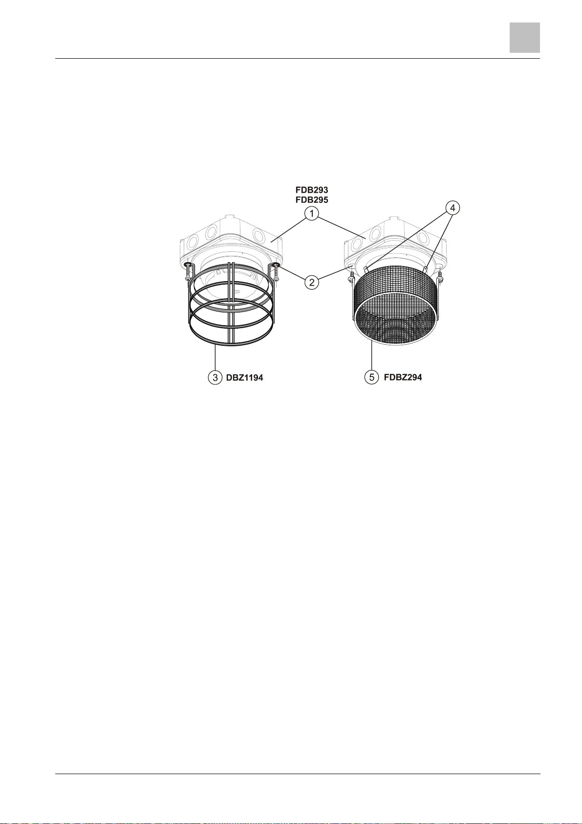
Protective c age DBZ1194 protects the detector against mechanical damage.
EMC-protective cage FDBZ294 protects the detector against mechanical damage
and electromagnetic fields.
5.11.1 I nstallation of the protective cages
The protect ive cages can only be installed on the base attachment wet FDB295.
Mounting / Installation
5
Installation of the protective cages
Base attac h me nt 4 Flat plug 6.3 x 0.8 mm
1
2
Break ou t and screw protective cage on
firmly
3 Protective cage
5 EMC-protective cage
5.11.2 Grounding of the EMC-protective cage FDBZ294
The EMC-prot ective cage must be connected to the shielding of the detector line
cable at the flat plug.
If the detector line cable is not shielded then the EMC-protective cage must be
grounded using a separate cable.
For optimum grounding in the presence of powerful electromagnetic fields, the
ground line must be shorter than 10 m and have a cross section of at least
1.5 mm2.
47
Building Technologies A6V10316298_e_en_-Fire Safety 2014-05-21
Page 48
Mounting / Installation
Connection diagram
1b
E
O
L
3
42234
Use the detector bases DB110D and DB110RD if you are installing a fire
5
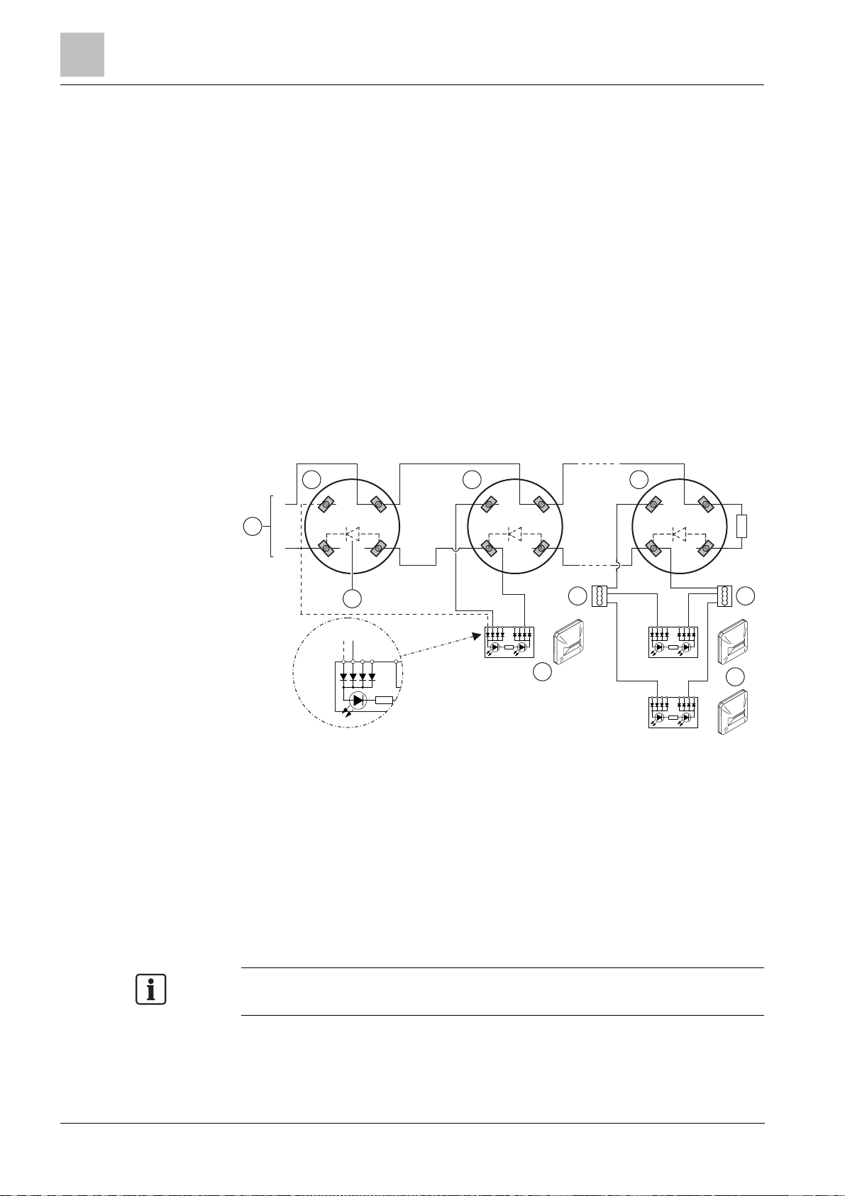
5.12 Connection diagram
Cables and topology
l The connection is established from detector base to detector base using
twisted or untwisted wire pairs.
l Wherever possible use twist ed, unshielded cables.
l Shielded cables are only required in special cases, such as strong high-
frequency fields.
Connecting external alarm indicators FDAI91 / FDAI92 / FDAI93
Observe the following points when connecting external alarm indicators:
l Wherever possible use twist ed, unshielded cables.
l Connect a maximum of two external alarm indicators to one detector.
l If a cable with shielding is used to connect the external alarm indicator, this
shielding must be linked t o the shielding of the detector line cable.
The shielding must not be linked to the external alarm indicator it self.
Connection diagram
2
1a 1b
+
1
-
Connection diagram for collective detector lines
1
Control panel 4 External alarm indicator
5 6
5
2 Detector base
DB110 / DB110x / DB110xx
1a 1b
5 6
+ +
- -
5 Diode (only with DB110D and
DB110RD)
1a
5 6
+
-
3 Auxiliary terminal DBZ1190-xx
detection system in accordance with BS 5839, part 1.
You will find more detailed information in the fire detection system documentation.
48
Building Technologies A6V10316298_e_en_--
Fire Safety 2014-05-21
Page 49

Commissioning
6 Commissioning
The devices are commissioned via the control panel. The exact procedure is
described in the control panel documentation.
6
49
Building Technologies A6V10316298_e_en_-Fire Safety 2014-05-21
Page 50

Maintenance / Repair
Performance check
Once the detector line has been started up or reset, the smoke detector OH110
To trigger a point detector wi
th test gas, normally 2…4
gas discharges are
7
7 Maintenance / Repair
7.1 Performance check
The selftest aut omatically subjects the point detec tors to an extensive electrical
performance check. Regular performance checks of the point detectors are
required nonetheless. This may be done with the t est gas or hot air fan depending
on the detector type.
Recommendation:
l Check the devices every year.
l Replace heavily soile d or damaged devic es.
l All point detectors should be replaced after 6 to 8 years of service, depending
on the ambient conditions.
7.2 Testing the point detector
Depending on the point detector, testing may be performed wit h one or more of the
following accessories :
l Test gas
– REF8-S (recommended)
– REF8
l Hot air fan
has a reduced response time in the 'Robust' parameter set for a period of
3 minutes. It is possible to test the point detector with test gas during this period.
Simplified test readiness of the point detector is indicated by the green LED
flashing three times every 10 s.
The following table shows which point detectors may be tested with which test aids:
Detector Test gas Hot air fan
OH110 X X
OP110 X –
HI110 – X
HI112 – X
X = Testing equipment is suitable
– = Testing equipment is not suitable
required at intervals of approx. 2 seconds. When the detector is in test mode,
activation t akes place after approximately 10 seconds.
See also
2 Internal alarm indicator [➙ 20]
2 Test mode [➙ 21]
50
Building Technologies A6V10316298_e_en_--
Fire Safety 2014-05-21
Page 51

Technical data for multi
-
sensor fire detector OH110
8 Specifications
Unless otherwise mentioned, the following data applies:
Temperature = 25 °C
Air pressure = 1000 hPa (750 Torr)
8.1 Technical data for multi-sensor fire detector OH110
You will find information on approvals, CE marking, and the relevant EU directives
for this device (these devices) in the following document(s); see 'Applicable
documents' chapt er:
l Document A6V10301051
Detector line Operating voltage DC 16…28 V
Maximum current connection factor 1
Max. 100 μA
160 μA
4…50 mA
Max. 2
2.5 or 3.5 %/m (depending on the parameter
set)
External alarm indicators
Device characteristics
Connections
Quiescent current at maximum current
connection factor
Surge current at maximum current
connection factor
Alarm voltage at:
l Alarm current = 1…15 mA DC 5…10 V
l Alarm current = 35 mA DC 18…22 V
l Alarm current = 50 mA DC 26…28 V
Alarm current at operating voltage
UB = DC 5…28 V
Reset voltage UR:
l Alarm is reliably reset DC 0…2 V
l Alarm may possibly not be reset DC 2…4 V
Protocol Collective (with and without current limitation)
Compatibility See 'List of compatibility'
Number of external alarm indicators that
can be connected
Voltage DC 9…30 V
Current 10…16 mA
Response sensitivity
at 0.2 m/s (typ.)
Permissible wind speed Max. 5 m/s
Compensation speed ≤1/45 voltage increase for detection/h
Flashing interval times AI: See chapter 'Internal alarm indicator'
Detector line and external alarm
indicators:
l Design Screw te rminal
l Cable cross section 2 x 0.2…1.6 mm
Specifications
2
8
Building Technologies A6V10316298_e_en_-Fire Safety 2014-05-21
51
Page 52

8
Technical data for smoke detector OP110
Specifications
Ambient conditions
Mechanical data Color ∼RAL 9010 pure white
Standards European standards l CEA 4021
Operating temperature/permissible
ambient temperature
Storage temperature -30…+70 °C
Air humidity ≤95 % rel.
Protection categories according to
EN 60529 / IEC 60529:
l Bases DB110, DB110x, DB110xx
(all installation types)
l Bases DB110, DB110x, DB110xx
with detector base seal RS720
l Bases DB110, DB110x, DB110xx
with base attachment wet BA721
Electromagnetic compatibility:
l 10 kHz…1.8 GHz 50 V/m
l 1.8 GHz…2.5 GHz 20 V/m
-10…+50 °C
IP40
IP42
IP44
l EN 54-7
8.2 Technical data for smoke detector OP110
You will find information on approvals, CE marking, and the relevant EU directives
for this device (these devices) in the following document(s); see 'Applicable
documents' chapt er:
l Document A6V10301051
Detector line Operating voltage DC 16…28 V
Maximum current connection factor 1
Max. 100 μA
160 μA
4…50 mA
Max. 2
External alarm indicators
Quiescent current at maximum current
connection factor
Surge current at maximum current
connection factor
Alarm voltage at:
l Alarm current = 1…15 mA DC 5…10 V
l Alarm current = 35 mA DC 18…22 V
l Alarm current = 50 mA DC 26…28 V
Alarm current at operating voltage
UB = DC 5…28 V
Reset voltage UR:
l Alarm is reliably reset DC 0…2 V
l Alarm may possibly not be reset DC 2…4 V
Protocol Collective (with and without current limitation)
Compatibility See 'List of compatibility'
Number of external alarm indicators that
can be connected
Voltage DC 9…30 V
Current 10…16 mA
52
Building Technologies A6V10316298_e_en_--
Fire Safety 2014-05-21
Page 53

Specifications
Technical data for smoke detector OP110
8
Device characteristics
Response sensitivity
at 0.2 m/s (typ.)
1.8 or 2.5 %/m (depending on the parameter
set)
Permissible wind speed Max. 5 m/s
Compensation speed ≤1/45 voltage increase for detection/h
Flashing interval times AI: See chapter 'Internal alarm indicator'
Connections
Detector line and external alarm
indicators:
l Design Screw terminal
2
Ambient conditions
l Cable cross section 2 x 0.2…1.6 mm
Operating temperature/permissible
-10…+50 °C
ambient temperature
Storage temperature -30…+70 °C
Air humidity ≤95 % rel.
Protection categories according to
EN 60529 / IEC 60529:
l Bases DB110, DB110x, DB110xx
IP40
(all installation types)
l Bases DB110, DB110x, DB110xx with
IP42
detector base seal RS720
l Bases DB110, DB110x, DB110xx with
IP44
base attachment wet BA721
Electromagnetic compatibility:
l 10 kHz…1.8 GHz 50 V/m
l 1.8 GHz…2.5 GHz 20 V/m
Mechanical data Color ∼RAL 9010 pure white
Standards European standards EN 54-7
Building Technologies A6V10316298_e_en_-Fire Safety 2014-05-21
53
Page 54

Specifications
Technical data for heat detectors HI110 / HI112
8
8.3 Technical data for heat detectors HI110 / HI112
You will find information on approvals, CE marking, and the relevant EU directives
for this device (these devices) in the following document(s); see 'Applicable
documents' chapt er:
l Document A6V10301051
Detector line Operating voltage DC 16…28 V
Maximum current connection factor 1
Quiescent current at maximum current
connection factor
Surge current at maximum current
connection factor
Alarm voltage at:
l Alarm current = 1…15 mA DC 5…10 V
l Alarm current = 35 mA DC 18…22 V
l Alarm current = 50 mA DC 26…28 V
Alarm current at operating voltage
UB = DC 5…28 V
Reset voltage UR:
l Alarm is reliably reset DC 0…2 V
l Alarm may possibly not be reset DC 2…4 V
Protocol Collective (with and without current limitation)
Compatibility See 'List of compatibility'
External alarm indicators
Device characteristics for
HI110
Device characteristics for
HI112
Connections Detector line and external alarm indicators:
Number of external alarm indicators that
can be connected
Voltage DC 9…30 V
Current 10…16 mA
Static response temperature with
parameter set:
l 'A1R' (typ.) 60 °C
Flashing interval times AI: See chapter 'Internal alarm indicator'
Static response temperature with
parameter set:
l 'A2S' (typ.) 60 °C
l 'B' (typ.) 80 °C
Flashing interval times AI: See chapter 'Internal alarm indicator'
l Design Screw terminal
l Cable cross section 2 x 0.2…1.6 mm
Max. 100 μA
160 μA
4…50 mA
Max. 2
2
54
Building Technologies A6V10316298_e_en_--
Fire Safety 2014-05-21
Page 55

Specifications
Technical data for heat detectors HI110 / HI112
8
Ambient conditions
Mechanical data Color ∼RAL 9010 pure white
Standards European standards EN 54-5
Operating temperature/permissible
ambient temperature:
l HI110 -10…+50 °C
l HI112 with 'A2S' parameter set -10…+50 °C
l HI112 with 'B' parameter set -10…+65 °C
Storage temperature -30…+70 °C
Air humidity ≤95 % rel.
Protection categories according to
EN 60529 / IEC 60529:
l Bases DB110, DB110x, DB110xx
(all installation types)
l Bases DB110, DB110x, DB110xx with
detector base seal RS720
l Bases DB110, DB110x, DB110xx with
base attachment wet BA721
Electromagnetic compatibility:
l 10 kHz…1.8 GHz 50 V/m
l 1.8 GHz…2.5 GHz 20 V/m
IP40
IP42
IP44
Building Technologies A6V10316298_e_en_-Fire Safety 2014-05-21
55
Page 56
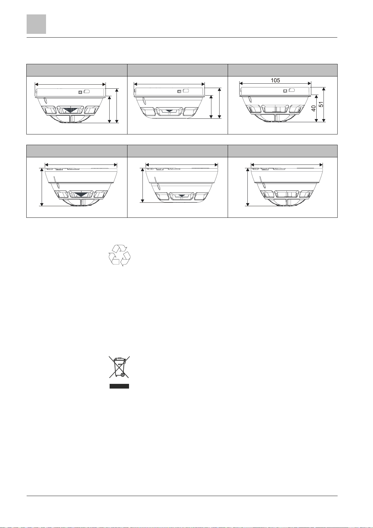
8
Dimensions
105
105
117
6
2
117
5
6
117
6
2
Specifications
8.4 Dimensions
OH110 OP110 HI110, HI112
51
40
OH110 with base OP110 with base HI110, HI112 with base
45
34
8.5 Environmental compatibility and disposal
This device is manuf actured using materials and procedures which
comply with current environmental protection standards as best as
possible. More specifically, the following measures have been
undertaken:
l Use of reusable materials
l Use of halogen-free plastics
l Elect ronic parts and synthetic materials can be separated
Larger plastic part s are labeled according to ISO 11469 and ISO 1043.
The plastics can be separated and recycled on this basis.
Electronic parts and batteries must not be disposed of wit h domestic
waste.
l T ake electronic parts and batteries to local collection points or
recycling centers.
l Contact local aut horities f or more information.
l Observe national requirements for disposing of electronic parts
and batteries.
56
Building Technologies A6V10316298_e_en_--
Fire Safety 2014-05-21
Page 57

Index
Index
A
Alarm indicator
External, 21
Approvals, 51, 52, 54
Auxiliary terminals
Connection terminal, 43
Micro terminal, 43
C
Cables, 48
CE marking, 51, 52, 54
Commissioning det ectors, 49
Compatibility , 29
Connection diagram, 48
External alarm indic ators, 48
Connection terminal, 43
Control panel, 49
D
Designation plate
Detector base, 42
Installation, 42
Sounder base, 42
Detector base, 22
Detector base seal
Installation, 36
Detector dust cap, 44
Detector exchanger, 34
Detector heating unit
Installation, 45
Detector line
Connection diagram, 48
Detector locking device
Installation, 41
Disposal , 56
Documentation for fire detection syst em, 7
Download center
URL, 7
E
Environmenta l compatibility, 56
ES
Product version, 15
EU directives, 51, 52, 54
External alarm indic ators, 21
H
Heat detector , 18
Differential, 14
Static, 14
Hot air fan, 50
L
List of compatibility, 7, 29, 51, 52, 54
M
Maintenance int ervals, 50
Micro terminal, 43
Multi-sensor f ire detector, 14, 16
P
Packaging label
Product version, 15
Parameter set s, 19
Heat detector, 32
Multi-sensor f ire detector, 29
Smoke detector, 31
Performance check, 50
Point detector
Performance check, 50
Product label
Product version, 15
R
Recycling, 56
Required space, 34
S
Scope, 5
Screw terminals
Assignment, 43
Smoke detector, 14, 17
Standards, 52, 53, 55
57
Building Technologies A6V10316298_e_en_-Fire Safety 2014-05-21
Page 58

Index
T
Test gas
REF8, 50
REF8-S, 50
Test mode, 21
Testing equipment
Hot air fan, 21, 50
Test gas, 50
Test gas REF8, 21
Test gas REF8-S, 21
Topology, 48
Type plate
Product version, 15
W
Wide-spectrum smoke detector, 17
58
Building Technologies A6V10316298_e_en_--
Fire Safety 2014-05-21
Page 59

Index
59
Building Technologies A6V10316298_e_en_-Fire Safety 2014-05-21
Page 60

Issued by
Siemens S witzerland Ltd
© 2012
-
2014 Copyright Si em ens Switze rland Ltd
Infrastructure & Cities Sector
Building Technologies Division
International Headquarters
Gubel strasse 22
CH-6301 Zug
Tel. +41 41-724 24 24
www.siemens.com/buildingtechnologies
Document ID A6V10316298_e_en_-- Manual FD720
Edition 2014-05-21 Section 2
Technical specifications and availability subject to change without notice.
 Loading...