

Page 1
GAMMA instabus
Technical product information
December 2009
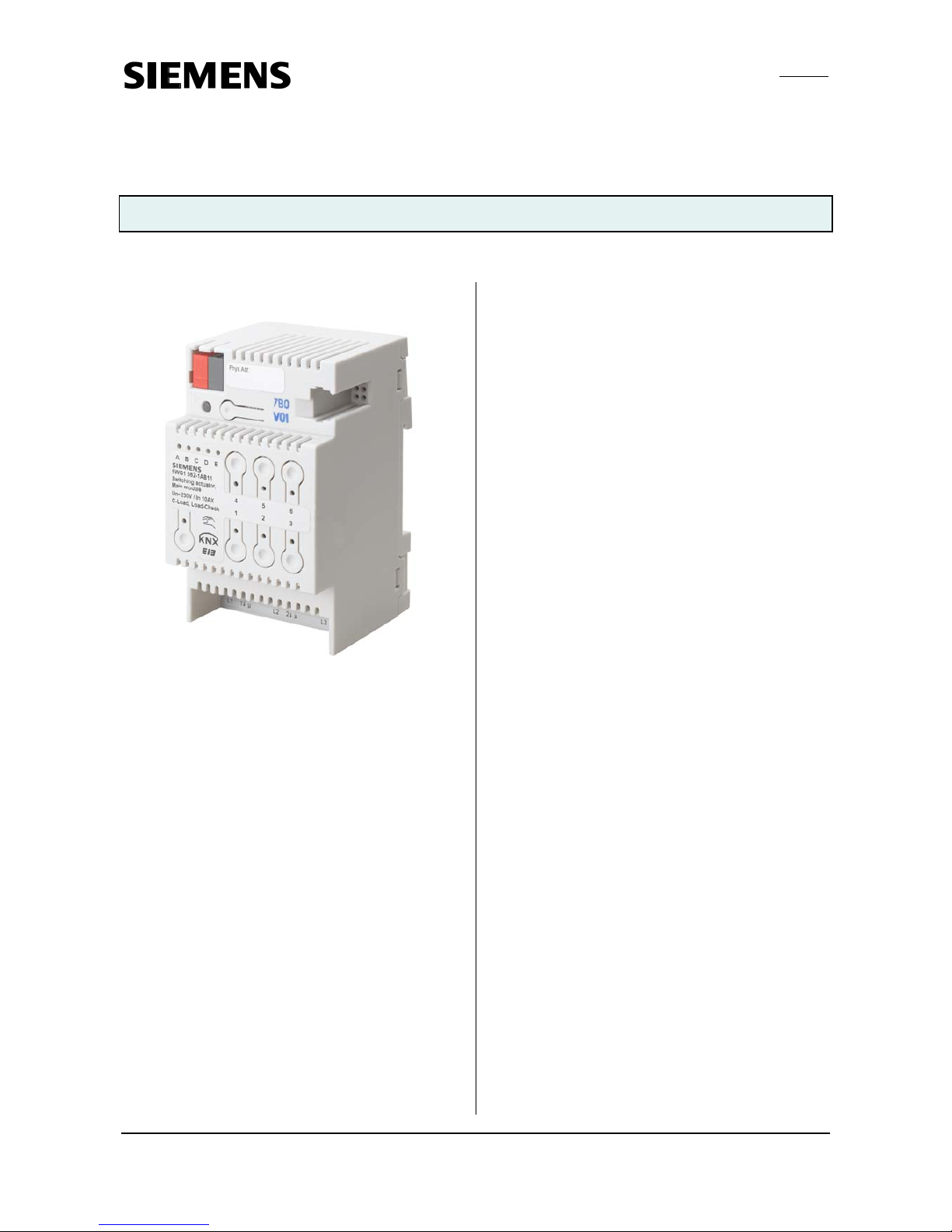
N 562/11 Switching actuator, main module 5WG1 562-1AB11
3x AC 230/400 V, 10 AX, C-load, load-check
Siemens AG N 562/11, 6 pages Technical manual
Industry Sector, Building Technologies
Low Voltage Distribution © Siemens AG 2009 Update: http://www.siemens.com/gamma
P.O. Box 100953, D-93009 Regensburg Subject to change without further notice
2.4.3.4/1
Product and functional description
The switching actuator main module N 562/11 is a DINrail mounted device with N-system dimensions. It can
switch three groups of electrical consumers, independent
of each other, via its three relay contact outputs. The bus
is connected via a bus terminal block. The actuator electronics are supplied via the bus voltage.
Connection of switching actuator submodules
A switching actuator submodule N 562/21 or N 512/21
(see device B in figure 1) can be connected to the switching actuator main module N 562/11 (see device A in
figure 1) via the 6-pin interface with a special jumper. A
further switching actuator submodule can be connected
likewise to a previous switching actuator submodule. In
total up to 4 switching actuator submodules N 562/21 or
N 512/21 can be connected in series to a switching actuator main module N 562/11, so that a main module, if
need be, can be extended simply from a 3-fold to a 6-, 9-,
12- or 15-fold switching actuator and thus be matched
flexibly to the size and number of loads to be switched.
LED display
Five green light emitting diodes (LED) on the top of the
main module (see figure 2, A5) indicate which module is
selected (LED = ON). A module can be selected by tapping the pushbutton “Direct mode” (see figure 2, A6)
once or several times until the LED of the desired module
A to E illuminates. If any of the green LED A to E is flashing a fault was detected at this module. For example, this
is the case if more modules are configured than are actually connected or if the configured module type does not
correspond with the module type actually connected or if
a module is detected as faulty.
Bus mode / Direct mode
The Direct mode pushbutton (see figure 2, A6) with an
integrated yellow LED may be used to toggle between
Bus mode and Direct mode. If this pushbutton is pressed
briefly, the associated green LED indicates for 30 seconds
which of the modules A to E (see figure 2, A5) was selected last and the switching state of the corresponding
outputs is indicated by the red LED integrated in buttons
1 to 3 (see figure 2, A9; relay contact closed: LED = ON,
contact open: LED = OFF).
However, if the button to switch on Direct mode is held
down for at least 3 seconds, then the yellow LED to indicate Direct mode turns on permanently. In Direct mode,
each output of the currently selected module can be
switched via the allocated pushbutton on the top of the
main module through a toggling function: a first press on
the pushbutton switches the output on if it is switched
off, a second press switches it off again. The switching
state of the output is indicated by the red LED incorporated in the pushbutton. (Note: Pushbuttons 4 to 6 and
the incorporated LED are not used in the N 562/11.) To
change the switching state of the outputs of another
module, this module must be selected first. To do this,
you must briefly press the Direct mode pushbutton several times until the LED of the desired module A to E
illuminates. Modules that are connected but not yet set
up as connected cannot be selected.
A parameter determines whether Direct mode can be
switched on permanently or for a limited period. The
factory default setting limits the Direct mode period to
15 minutes. Each time the pushbutton is pressed the
timer is reset to 15 minutes. After the period has elapsed
without a further key press, Direct mode is switched off
automatically and Bus mode is re-enabled accordingly (if
communication via the bus is possible). Alternatively,
Direct mode can be left at any time by pressing the Direct
mode pushbutton for at least 3 seconds. Then the yellow
LED for indicating Direct mode turns off and the actuator
operates in Bus mode. In Bus mode, pressing the
pushbutton for direct switching of an output off or on
does not work. If Direct mode is active, switching and
scene recall commands received via the bus are buffered
and automatically executed after switching back to Bus
mode.
Behavior in case of mains failure / recovery
Because the actuator electronics are fed from the bus, a
mains failure then leads solely to a failure of the actuator
function if the bus voltage also fails as the result of a
mains failure. However, it can be set for each actuator
output individually which switching state it is to assume
on a bus voltage failure and after the bus voltage recovery: as before bus voltage failure, ON or OFF.
Page 2
GAMMA instabus
Technical product information
December 2009
N 562/11 Switching actuator, main module 5WG1 562-1AB11
3x AC 230/400 V, 10 AX, C-load, load-check
Technical manual N 562/11, 6 pages Siemens AG
Industry Sector, Building Technologies
Update: http://www.siemens.com/gamma © Siemens AG 2009 Low Voltage Distribution
Subject to change without further notice P.O. Box 100953, D-93009 Regensburg
2.4.3.4/2
Application program
The N 562/11 switching actuator needs the application
program "07B0 A15 Switching Actuator 982001". This
controls the outputs of the main module as well as the
outputs of all connected submodules via their 6-pole
interfaces.
In bus mode, a communication object can be available
for each actuator output - for switching, for manual
override, for a forced control, for a logical combination
and for status query. Furthermore, if required, timelimited switching instead of permanent switching on can
be enabled for each channel via an optional "Night
mode" object (e.g. for lighting while cleaning), if need be
with a warning before switching off by multiple switching the output on and off (flashing). It can also be selected whether all a module's outputs are to be set jointly
and thus identically or whether each output is to be
configured separately and individually.
Besides other functions, the N 562/11's comprehensive
application program includes measuring and monitoring
the load current for each output on load failure and overload, simultaneous switching of all 3 outputs (3-phase
switching), converting a speed preset as a percentage
into 1- to 3-stage switching commands (fan speed control), conversion of a valve setting preset as a percentage
into a pulse width modulated switching command
(thermal drive control), a switching cycle and runtime
totalization with threshold monitoring for each output
and an integrated 8-bit scene control, in which each
output can be incorporated into up to 8 scenes.
To load the application program, the Engineering Tool
Software (ETS) is required as version 3.0 f or higher.
Note
: If the N 562/11 application program is "unloaded"
with the ETS, then you will no longer be able to activate
direct mode, i.e. the LED status display and local switching of the outputs using the buttons on the front panel
of the actuator are disabled. Only after reloading the
application program you can re-enable the status display
and direct mode.
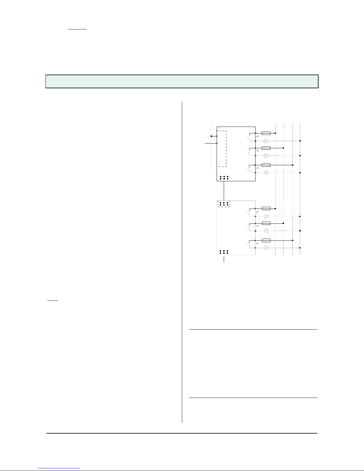
Connection example
Schaltaktor, Hauptmodul
Switching actuator, main module
N 562/11
B
u
s
a
n
k
o
p
p
l
e
r
B
u
s
c
o
u
p
l
i
n
g
u
n
i
t
K
N
X
Ausgang 1
Output 1
Ausgang 2
Output 2
Ausgang 3
Output 3
L1
L2
L3
N
L1
L2
L3
2
3
1
A
Schaltaktor, Erweiterung
Switching actuator, submodule
N 562/21 / N512/21
6
Ausgang 1
Output 1
Ausgang 2
Output 2
Ausgang 3
Output 3
L2
L3
2
1
L1
B
C ... E
3
Figure 1. Connection example
Installation notes
• The device can be used for permanent installation in
dry interior rooms and for insertion in distribution
boards or miniature housings.
V
DANGER
• The device must be mounted and commissioned by an
authorised electrician.
• When connecting the device, it should be ensured that
the device can be isolated.
• The device must not be opened.
• For planning and construction of electric installations,
the relevant guidelines, regulations and standards of
the respective country are to be considered.
• With the last submodule no bridging connector must
be plugged into the jack for a further submodule on
the right submodule side.
Page 3

GAMMA instabus
Technical product information
December 2009
N 562/11 Switching actuator, main module 5WG1 562-1AB11
3x AC 230/400 V, 10 AX, C-load, load-check
Siemens AG N 562/11, 6 pages Technical manual
Industry Sector, Building Technologies
Low Voltage Distribution © Siemens AG 2009 Update: http://www.siemens.com/gamma
P.O. Box 100953, D-93009 Regensburg Subject to change without further notice
2.4.3.4/3
Technical data
Power supply
• Bus voltage: supplied via the bus line
• Bus current, main module: typically 7 mA, max. 22 mA
main module + 4x submodule: typ. 11 mA, max. 26 mA
• Power dissipation: if all outputs = OFF: 0.2 W,
at max. load and all outputs = ON: approx. 3.5 W.
Outputs
• 3 switching outputs, potential-free relay contacts:
- rated voltage: AC 230/400 V, 50/60 Hz
- rated current: 10 AX (140 µF) to DIN EN 60669-1,
16 A in AC1 mode (cos ϕ = 0.8) and 10 A in AC3 mode
(cos ϕ = 0.45) as to DIN EN 60947-4-1,
- DC switching capacity: 10A at 24V DC
- Min. switching capacity: 100 mA at 12V AC
- Incandescent lamp load: max. 2,300 W
- LV halogen lamps, inductive transformer: 1,200 W
- LV halogen lamps, electronic transformer: 1,500 W
- Number of OSRAM ballasts for T5/T8:
QTI 1x28/54W: 37, QTP 1x36W: 16,
QT-M 1x26-42W:11, QTP 2x58W: 5,
QT-FQ 1x80W: 5
- Mech. lifetime: > 1,000,000 switching cycles
- Electr. lifetime: > 100,000 at AC1, > 30,000 at AC3
- Load current measuring range: 0.1...16 A,sinusoidal
- Load current frequency range: 50/60 Hz, +/- 5 Hz,
- Measuring accuracy: +/- 9 % of the current measured
value and +/- 100 mA,
- Max. relay position changes per output and evenly
distributed per minute with simultaneous switching of
all relays: 20 with 3 outputs, 10 with 6 outputs, 7 with
9 outputs, 5 with 12 outputs, 4 with 15 outputs.
Operating elements
• 1 pushbutton:
for toggling between normal mode / addressing mode
• 1 pushbutton:
for toggling between bus mode / direct mode
• 2x 3 pushbuttons (in 2 rows):
for direct operation (toggling) of 3 actuator outputs
per row, independent of the bus.
Display elements
• 1 red LED: for checking the bus voltage and for display-
ing normal mode / addressing mode
• 5 green LED: for display of the selected module
• 1 yellow LED: for displaying direct mode / bus mode
• 1 red LED per pushbutton for direct operation:
for displaying whether the output is switched on or off
Connections
• Output circuits: screw-type terminals,
insulation strip length 7... 9 mm
The following conductor cross-sections are permitted:
- 0.5... 4.0 mm² single-core,
- 0.5... 2.5 mm² finely stranded without / with connec-
tor sleeve
• Each L-conductor connection to the N 562/11 must be
fused, depending on the type of load, with a circuitbreaker of characteristic B or C for a max. nominal current of 10 A resp. 16 A!
• KNX bus line: bus terminal block
• 2x 6-pole jack: for bridging connector.
Mechanical data
• Housing: plastic
• Dimensions: DIN rail mounted device in N dimensions,
width 3 module units (1 module unit = 18 mm)
• Weight: approx. 240 g
• Fire load: approx. 3400 kJ
• Installation: Snap-on mounting on DIN rail
EN 60715-TH35-7.50
Electrical safety
• Degree of pollution (according to IEC 60664-1): 2
• Type of protection (according to EN 60529): IP 20
• Overvoltage category (according to IEC 60664-1): III
• Bus: safety extra-low voltage SELV DC 24 V
• Device complies with: EN 50090-2-2 and EN 60669-2-1
EMC requirements
• Complies with EN 50090-2-2, EN 50428 and
EN 60669-2-1
Environmental conditions
• Climatic withstand capability: EN 50090-2-2
• Ambient operating temperature: - 5 ... + 45 °C
• Storage temperature: - 25 ... + 70 °C
• Relative humidity (not condensing): 5 % to 93 %
Reliability
• Failure rate: 1040 fit at 40°C
Markings
• KNX EIB
CE mark
• In accordance with the EMC guideline (residential and
functional buildings), low voltage guideline
Page 4

GAMMA instabus
Technical product information
December 2009
N 562/11 Switching actuator, main module 5WG1 562-1AB11
3x AC 230/400 V, 10 AX, C-load, load-check
Technical manual N 562/11, 6 pages Siemens AG
Industry Sector, Building Technologies
Update: http://www.siemens.com/gamma © Siemens AG 2009 Low Voltage Distribution
Subject to change without further notice P.O. Box 100953, D-93009 Regensburg
2.4.3.4/4
Location and function of the display and
operating elements
A1
A4
A10
A11
A9
A8
A12
A6
A7
A5
A3
A2
Figure 2. Display and operating elements
A1 Plug for bus connection terminal block
A2 Pushbutton for switching between normal / address-
ing mode for transferring the physical address.
A3 LED for indicating normal mode (LED Off) or address-
ing mode (LED On); it turns off automatically after
transferring the physical address
A4 Jack for connection of a switching actuator sub-
module
A5 LED to indicate the selected device
A6 Pushbutton to toggle between Bus / Direct mode
A7 LED to indicate Direct mode = On
A8 Pushbutton for direct operation of outputs 1...3
A9 LED to indicate whether the corresponding output is
switched on or off.
A10 Without function
A11 Without function
A12 Screw-type terminals of outputs 1...3
Installation and wiring
Mounting / dismounting the device
:
see figure 3 and 4
Figure 3. Mounting the device
Figure 4. Dismounting the device
Connecting / disconnecting the bus cable: see figure 5
D2
D2.4
D2
D2.4
5 mm
D2.1 D2.2
2
D2.3
D
Figure 5. Connecting / disconnecting the bus cable
Connecting a switching actuator submodule: see figure 6
Snap the switching actuator submodule on to the rail
and push it to the left against the switching actuator
main module or against the switching actuator submodule. Connect both devices using the bridging connector supplied.
AB C
Figure 6. Connecting a switching actuator submodule
B1
B2
C3
C1
C2
Page 5

GAMMA instabus
Technical product information
December 2009
N 562/11 Switching actuator, main module 5WG1 562-1AB11
3x AC 230/400 V, 10 AX, C-load, load-check
Siemens AG N 562/11, 6 pages Technical manual
Industry Sector, Building Technologies
Low Voltage Distribution © Siemens AG 2009 Update: http://www.siemens.com/gamma
P.O. Box 100953, D-93009 Regensburg Subject to change without further notice
2.4.3.4/5
General notes
• The operating instructions must be handed over to the
client.
• A faulty device shall be sent with a Return Good Note
for Service provided by the appropriate Siemens sales
office to the following address:
SIEMENS AG, Siemensstr. 10, D-93055 Regensburg
• If you have further questions concerning the product
please contact our technical support:
℡ +49 (0) 180 50 50-222
(0,14 €/min. from the German landline network, deviating mobile communications prices are possible)
+49 (0) 180 50 50-223
E-Mail: support.automation@siemens.com
www.siemens.com/automation/support-request
Page 6

GAMMA instabus
Technical product information
December 2009
N 562/11 Switching actuator, main module 5WG1 562-1AB11
3x AC 230/400 V, 10 AX, C-load, load-check
Technical manual N 562/11, 6 pages Siemens AG
Industry Sector, Building Technologies
Update: http://www.siemens.com/gamma © Siemens AG 2009 Low Voltage Distribution
Subject to change without further notice P.O. Box 100953, D-93009 Regensburg
2.4.3.4/6
Space for notes
 Loading...