

Page 1

Moser
MOBILETT XP Digital
Installation and Start-up
System
SP
Installation and Start-up
01818447
Print No.:
Replaces: SPR8-230.814.30.02.02
SPR8-230.814.30.03.02
© Siemens AG
The reproduction, transmission or use
of this document or its contents is not
permitted without express written
authority. Offenders will be liable for
damages. All rights, including rights
created by patent grant or registration
of a utility model or design, are
reserved.
English
Doc. Gen. Date: 11.05
2005
Page 2

2 Revision / Disclaimer
1Revision / Disclaimer
Document revision level
The document corresponds to the version/revision level effective at the time of system
delivery. Revisions to hardcopy documentation are not automatically distributed.
Please contact your local Siemens office to order current revision levels.
Disclaimer
The installation and service of equipment described herein is to be performed by qualified
personnel who are employed by Siemens or one of its affiliates or who are otherwise
authorized by Siemens or one of its affiliates to provide such services.
Assemblers and other persons who are not employed by or otherwise directly affiliated
with or authorized by Siemens or one of its affiliates are directed to contact one of the
local offices of Siemens or one of its affiliates before attempting installation or service procedures.
MOBILETT XP Digital SPR8-230.814.30.03.02 Siemens AG
11.05 CS SD 24
Page 2 of 70
Medical Solutions
Page 3

Table of Contents 3
1- 0Table of Contents
1 _______ General ________________________________________________________ 6
Performance of work . . . . . . . . . . . . . . . . . . . . . . . . . . . . . . . . . . . . . . . . . . . . . . . . . . . . 6
Text labeling . . . . . . . . . . . . . . . . . . . . . . . . . . . . . . . . . . . . . . . . . . . . . . . . . . . . . . . . . . . 7
Icons. . . . . . . . . . . . . . . . . . . . . . . . . . . . . . . . . . . . . . . . . . . . . . . . . . . . . . . . . . . . . . . . . 8
Information on product safety and protective measures. . . . . . . . . . . . . . . . . . . . . . . . . . 9
System overview - user . . . . . . . . . . . . . . . . . . . . . . . . . . . . . . . . . . . . . . . . . . . . . . . . . 12
Orientation . . . . . . . . . . . . . . . . . . . . . . . . . . . . . . . . . . . . . . . . . . . . . . . . . . . . . . . . . . . 13
System overview - service . . . . . . . . . . . . . . . . . . . . . . . . . . . . . . . . . . . . . . . . . . . . . . . 14
Cleaning . . . . . . . . . . . . . . . . . . . . . . . . . . . . . . . . . . . . . . . . . . . . . . . . . . . . . . . . . . . . . 16
2 _______ General start-up information _____________________________________ 17
Required documents . . . . . . . . . . . . . . . . . . . . . . . . . . . . . . . . . . . . . . . . . . . . . . . . . . . 17
Required tools, test equipment and aids . . . . . . . . . . . . . . . . . . . . . . . . . . . . . . . . . . . . 18
Start-up information . . . . . . . . . . . . . . . . . . . . . . . . . . . . . . . . . . . . . . . . . . . . . . . . . . . . 19
Information on the protective conductor resistance test. . . . . . . . . . . . . . . . . . . . . . . . . 20
Information on measuring the leakage current. . . . . . . . . . . . . . . . . . . . . . . . . . . . . . . . 22
Information on measuring the patient leakage current . . . . . . . . . . . . . . . . . . . . . . . . . . 25
3 _______ Unpacking and visual inspection__________________________________ 27
Unpacking. . . . . . . . . . . . . . . . . . . . . . . . . . . . . . . . . . . . . . . . . . . . . . . . . . . . . . . . . . . . 27
Visual inspection. . . . . . . . . . . . . . . . . . . . . . . . . . . . . . . . . . . . . . . . . . . . . . . . . . . . . . . 28
Mechanical function test . . . . . . . . . . . . . . . . . . . . . . . . . . . . . . . . . . . . . . . . . . . . . . . . . 29
Cable winch . . . . . . . . . . . . . . . . . . . . . . . . . . . . . . . . . . . . . . . . . . . . . . . . . . . . . . . 29
Support arm movements. . . . . . . . . . . . . . . . . . . . . . . . . . . . . . . . . . . . . . . . . . . . . . 29
Single tank and collimator movements . . . . . . . . . . . . . . . . . . . . . . . . . . . . . . . . . . . 29
4 _______ Checking the shock sensors _____________________________________ 30
Checking the shock sensors. . . . . . . . . . . . . . . . . . . . . . . . . . . . . . . . . . . . . . . . . . . . . . 30
5 _______ Start-up _______________________________________________________ 31
Line voltage . . . . . . . . . . . . . . . . . . . . . . . . . . . . . . . . . . . . . . . . . . . . . . . . . . . . . . . . . . 31
Controls and displays . . . . . . . . . . . . . . . . . . . . . . . . . . . . . . . . . . . . . . . . . . . . . . . . . . . 32
Battery charging operation . . . . . . . . . . . . . . . . . . . . . . . . . . . . . . . . . . . . . . . . . . . . 32
Exposure operation. . . . . . . . . . . . . . . . . . . . . . . . . . . . . . . . . . . . . . . . . . . . . . . . . . 32
Lead apron holder. . . . . . . . . . . . . . . . . . . . . . . . . . . . . . . . . . . . . . . . . . . . . . . . . . . 33
Collimator function . . . . . . . . . . . . . . . . . . . . . . . . . . . . . . . . . . . . . . . . . . . . . . . . . . 34
Calibrating the CXDI detector. . . . . . . . . . . . . . . . . . . . . . . . . . . . . . . . . . . . . . . . . . . . . 35
Exposure release with high voltage . . . . . . . . . . . . . . . . . . . . . . . . . . . . . . . . . . . . . . . . 36
Checking the preparation limit time. . . . . . . . . . . . . . . . . . . . . . . . . . . . . . . . . . . . . . 36
Release an exposure . . . . . . . . . . . . . . . . . . . . . . . . . . . . . . . . . . . . . . . . . . . . . . . . 36
Manual exposure termination . . . . . . . . . . . . . . . . . . . . . . . . . . . . . . . . . . . . . . . . . . 36
Light field/radiation field. . . . . . . . . . . . . . . . . . . . . . . . . . . . . . . . . . . . . . . . . . . . . . . . . 37
Siemens AG SPR8-230.814.30.03.02 MOBILETT XP Digital
Medical Solutions
11.05 CS SD 24
Page 3 of 70
Page 4

4 Table of Contents
Evaluation: light field to radiation field . . . . . . . . . . . . . . . . . . . . . . . . . . . . . . . . . . . . 37
Configuration of the imaging system. . . . . . . . . . . . . . . . . . . . . . . . . . . . . . . . . . . . . . . . 39
Checking the image quality . . . . . . . . . . . . . . . . . . . . . . . . . . . . . . . . . . . . . . . . . . . . . . . 40
Options . . . . . . . . . . . . . . . . . . . . . . . . . . . . . . . . . . . . . . . . . . . . . . . . . . . . . . . . . . . . . . 41
DAP . . . . . . . . . . . . . . . . . . . . . . . . . . . . . . . . . . . . . . . . . . . . . . . . . . . . . . . . . . . . . . 41
Remote control . . . . . . . . . . . . . . . . . . . . . . . . . . . . . . . . . . . . . . . . . . . . . . . . . . . . . 41
6 _______ DHHS _________________________________________________________ 42
DHHS tests (USA only) . . . . . . . . . . . . . . . . . . . . . . . . . . . . . . . . . . . . . . . . . . . . . . . . . . 42
Test of kV accuracy. . . . . . . . . . . . . . . . . . . . . . . . . . . . . . . . . . . . . . . . . . . . . . . . . . . . . 43
kV meter method: . . . . . . . . . . . . . . . . . . . . . . . . . . . . . . . . . . . . . . . . . . . . . . . . . . . 43
Oscilloscope method: . . . . . . . . . . . . . . . . . . . . . . . . . . . . . . . . . . . . . . . . . . . . . . . . 44
Test of mAs accuracy . . . . . . . . . . . . . . . . . . . . . . . . . . . . . . . . . . . . . . . . . . . . . . . . . . . 46
Oscilloscope method: . . . . . . . . . . . . . . . . . . . . . . . . . . . . . . . . . . . . . . . . . . . . . . . . 46
mAs meter method: . . . . . . . . . . . . . . . . . . . . . . . . . . . . . . . . . . . . . . . . . . . . . . . . . 47
Reproducibility test . . . . . . . . . . . . . . . . . . . . . . . . . . . . . . . . . . . . . . . . . . . . . . . . . . . . . 48
7 _______ Backup _______________________________________________________ 51
Backup procedure . . . . . . . . . . . . . . . . . . . . . . . . . . . . . . . . . . . . . . . . . . . . . . . . . . . . . . 51
Backup of hard disks . . . . . . . . . . . . . . . . . . . . . . . . . . . . . . . . . . . . . . . . . . . . . . . . . 51
Backup of Configuration . . . . . . . . . . . . . . . . . . . . . . . . . . . . . . . . . . . . . . . . . . . . . . 52
8 _______ Remaining work ________________________________________________ 54
Final activities . . . . . . . . . . . . . . . . . . . . . . . . . . . . . . . . . . . . . . . . . . . . . . . . . . . . . . . . . 54
Protective conductor test . . . . . . . . . . . . . . . . . . . . . . . . . . . . . . . . . . . . . . . . . . . . . . 54
Leakage current measurement . . . . . . . . . . . . . . . . . . . . . . . . . . . . . . . . . . . . . . . . . 54
Patient leakage current measurement. . . . . . . . . . . . . . . . . . . . . . . . . . . . . . . . . . . . 54
Labels . . . . . . . . . . . . . . . . . . . . . . . . . . . . . . . . . . . . . . . . . . . . . . . . . . . . . . . . . . . . 55
Reports . . . . . . . . . . . . . . . . . . . . . . . . . . . . . . . . . . . . . . . . . . . . . . . . . . . . . . . . . . . 56
9 _______ Start-up report _________________________________________________ 57
MOBILETT XP Digital . . . . . . . . . . . . . . . . . . . . . . . . . . . . . . . . . . . . . . . . . . . . . . . . . . . 57
10 ______ DHHS report ___________________________________________________ 59
MOBILETT XP Digital . . . . . . . . . . . . . . . . . . . . . . . . . . . . . . . . . . . . . . . . . . . . . . . . . . . 59
11 ______ Electrical safety/reports _________________________________________ 61
Protective conductor resistance/report . . . . . . . . . . . . . . . . . . . . . . . . . . . . . . . . . . . . . . 61
Measuring circuit . . . . . . . . . . . . . . . . . . . . . . . . . . . . . . . . . . . . . . . . . . . . . . . . . . . . 62
Remarks: . . . . . . . . . . . . . . . . . . . . . . . . . . . . . . . . . . . . . . . . . . . . . . . . . . . . . . . . . . 62
Leakage current/report . . . . . . . . . . . . . . . . . . . . . . . . . . . . . . . . . . . . . . . . . . . . . . . . . . 63
Measuring circuit . . . . . . . . . . . . . . . . . . . . . . . . . . . . . . . . . . . . . . . . . . . . . . . . . . . . 64
Remarks: . . . . . . . . . . . . . . . . . . . . . . . . . . . . . . . . . . . . . . . . . . . . . . . . . . . . . . . . . . 65
Patient leakage current/report. . . . . . . . . . . . . . . . . . . . . . . . . . . . . . . . . . . . . . . . . . . . . 67
Measuring circuit . . . . . . . . . . . . . . . . . . . . . . . . . . . . . . . . . . . . . . . . . . . . . . . . . . . . 68
MOBILETT XP Digital SPR8-230.814.30.03.02 Siemens AG
11.05 CS SD 24
Page 4 of 70
Medical Solutions
Page 5

Table of Contents 5
Remarks:. . . . . . . . . . . . . . . . . . . . . . . . . . . . . . . . . . . . . . . . . . . . . . . . . . . . . . . . . . 68
12 ______ Changes to Previous Version_____________________________________ 69
Siemens AG SPR8-230.814.30.03.02 MOBILETT XP Digital
Medical Solutions
11.05 CS SD 24
Page 5 of 70
Page 6

6 General
1General
2-
Performance of work 0
Any technician duly assigned by the local Siemens office is authorized to perform maintenance and service work.
U Certain tasks may also be performed by other technical personnel (e.g. the customer's
hospital technicians). These tasks are marked by this icon.
It is absolutely necessary to
• follow all instructions in textual and graphic form and to
• use the specified tools, test equipment and aids.
You can also contact your national Siemens Uptime Service Center for support.
MOBILETT XP Digital SPR8-230.814.30.03.02 Siemens AG
11.05 CS SD 24
Page 6 of 70
Medical Solutions
Page 7
General 7
Text labeling 0
DANGER
WARNING
CAUTION
NOTICE
DANGER indicates an immediate danger that if disregarded will
cause death or serious physical injury.
¹
WARNING indicates a possible danger that if disregarded can
cause death or serious physical injury.
¹
CAUTION used with the safety alert icon indicates a possible danger that if disregarded will or can lead to minor or moderate physical injury and/or damage to property.
¹
NOTICE used without the safety alert icon indicates a possible
danger that if disregarded can or will lead to an undesirable outcome or state other than death, physical injury or property damage.
¹
NOTE
NOTE is used to indicate information that explains the proper way
to use devices or to carry out a process, i.e., provides pointers and
tips.
Siemens AG SPR8-230.814.30.03.02 MOBILETT XP Digital
Medical Solutions
11.05 CS SD 24
Page 7 of 70
Page 8

8 General
Icons 0
X Warning about ionizing radiation or radioactive substances. Tests and adjustments that
must be performed with the radiation switched on are indicated by this radiation warning
icon.
.
V Dangerous electrical voltage > 25 VAC or > 60 VDC.
C Caution! General hazard warning.
E ESD: Warning about electrostatically sensitive components.
P Report icon. Used to indicate entries in certificates.
U Certain tasks can also be performed by other technical personnel (e.g. the customer's
hospital technicians).
Fig. 1:
Certain sections apply only to the USA. These sections are marked with this icon.
MOBILETT XP Digital SPR8-230.814.30.03.02 Siemens AG
11.05 CS SD 24
Page 8 of 70
Medical Solutions
Page 9
General 9
Information on product safety and protective measures 0
DANGER
DANGER
While performing maintenance and service work
on the MOBILETT XP Digital with the covers removed,
it is possible to come into contact with components under voltage.
Carelessness can result in death or serious bodily injury.
When conducting maintenance and service work, follow:
¹ the product-specific safety information contained in the
technical documentation,
¹ and the general safety information (TD00-000.860.01...).
Remove or install components only if:
¹ - The system is switched off, and
¹ - The capacitors are discharged, and
¹ - The ESD guidelines are followed, and
¹ - The batteries have been disconnected.
DANGER
Releasing radiation:
¹ Checks and settings for which radiation must be
released are marked with the radiation warning symbol.
¹ Radiation protection measures must be used.
Siemens AG SPR8-230.814.30.03.02 MOBILETT XP Digital
Medical Solutions
11.05 CS SD 24
Page 9 of 70
Page 10

10 General
DANGER
To avoid electrical shock from components under voltage, also be
aware that:
The capacitors of the capacitor bank can be electrically charged
even when the system is switched off and the power cable is disconnected!
Individual capacitors of the capacitor bank may have been disconnected from the discharging circuit, erroneously or as a result of
failure, and can still be electrically charged!
Disconnect the battery blocks in the XP Digital prior to maintenance and service work!
Carelessness can result in death or serious bodily injury.
¹ Make sure that no parts or tools fall into the unit;
¹ Do not touch potentially dangerous
components(Fig.2/p.11)
¹ If loose parts must be removed from the unit, use only
insulated tools;
¹ Protect the work area so that no other persons are able
touch the unit while the covers are open or removed!
• Switch the unit off before servicing or maintenance. Always disconnect the power plug
first.
• Make sure that the main switch is switched off.
• The capacitor bank discharges to < 40 V in approx. 15 minutes.
¹ The safety covers can be removed after this period has elapsed.
• Prior to performing any work, it must be verified that areas with dangerous voltage are
voltage-free (Fig.2/p.11).
MOBILETT XP Digital SPR8-230.814.30.03.02 Siemens AG
11.05 CS SD 24
Page 10 of 70
Medical Solutions
Page 11

General 11
Fig. 2: Locations with dangerous voltage
V With housing covers open and safety covers removed.
Back:
Left side:
Right side:
CAUTION: DC voltage (300 V) from the battery block to PCB D982!
Always disconnect the battery plug from BK1-BK4.
CAUTION: DC voltage (440V) at capacitor bank (D927)
CAUTION: DC voltage (440V) directly at the capacitor bank!
CAUTION: DC voltage (440V) directly at the capacitor bank!
CAUTION: AC voltage (> 100 V or > 60 V - half line voltage) at power supplies U1 and U2 when the power cord is connected.
Siemens AG SPR8-230.814.30.03.02 MOBILETT XP Digital
Medical Solutions
11.05 CS SD 24
Page 11 of 70
Page 12
12 General
System overview - user 0
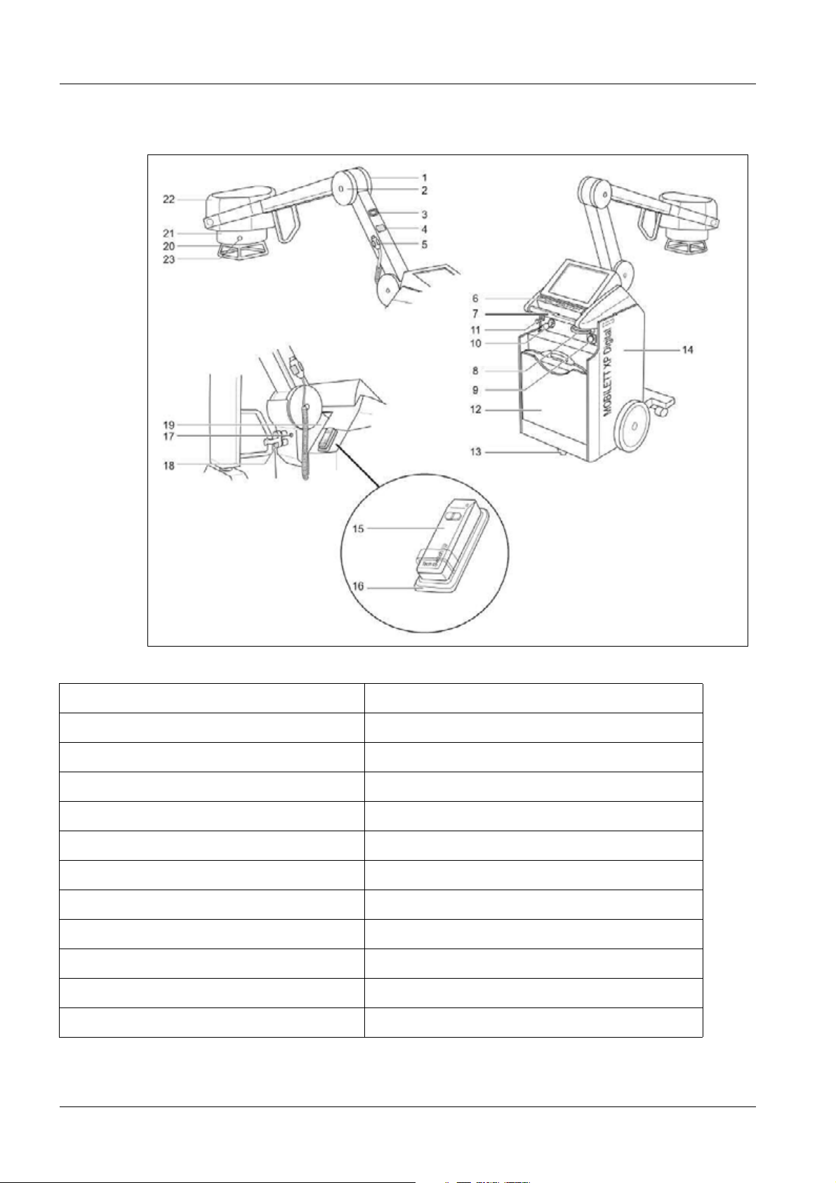
Fig. 3: User overview
(1) Hanger for lead apron (13) Castors
(2) Articulated arm (14) Console with chassis
(3) Sensor for IR remote control (optional) (15) IR remote control (optional)
(4) DAP display (optional) (16) Holder for IR remote control (optional)
(5) Exposure switch (S27) (17) Potential equalization connector
(6) Control panel and display field (18) Transport safety device
(7) Transport handle/motor control (19) Stand column
(8) Hand/parking brake handle (20) DAP ionization chamber (optional)
(9) Main switch (21) Collimator
(10) Power cord (22) X-ray tube assembly
(11) Brake handle for cable winch (23) Light localizer buttons (two sides)
(12) CXDI-50G detector holder n.a.
MOBILETT XP Digital SPR8-230.814.30.03.02 Siemens AG
11.05 CS SD 24
Page 12 of 70
Medical Solutions
Page 13
General 13
Orientation 0
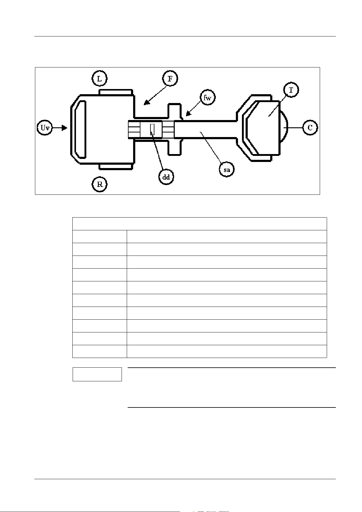
Fig. 4: Top view of system_01
System orientation to clarify the technical description
Abbreviations Explanation
Uv User view - back (User view)
L Left side of unit (left)
R Right side of unit (right)
F Front (front)
fw Front wheels (front wheels)
sa Support arm (support arm)
T Tube (single tank)
C Multileaf collimator (collimator)
dd DAP display (dose display)
NOTE
These orientation indicators are used in all technical documents.
Descriptions are always from the “forward travel” user view. Always use this perspective when communicating with third parties
(e.g., USC/HSC).
Siemens AG SPR8-230.814.30.03.02 MOBILETT XP Digital
Medical Solutions
11.05 CS SD 24
Page 13 of 70
Page 14
14 General
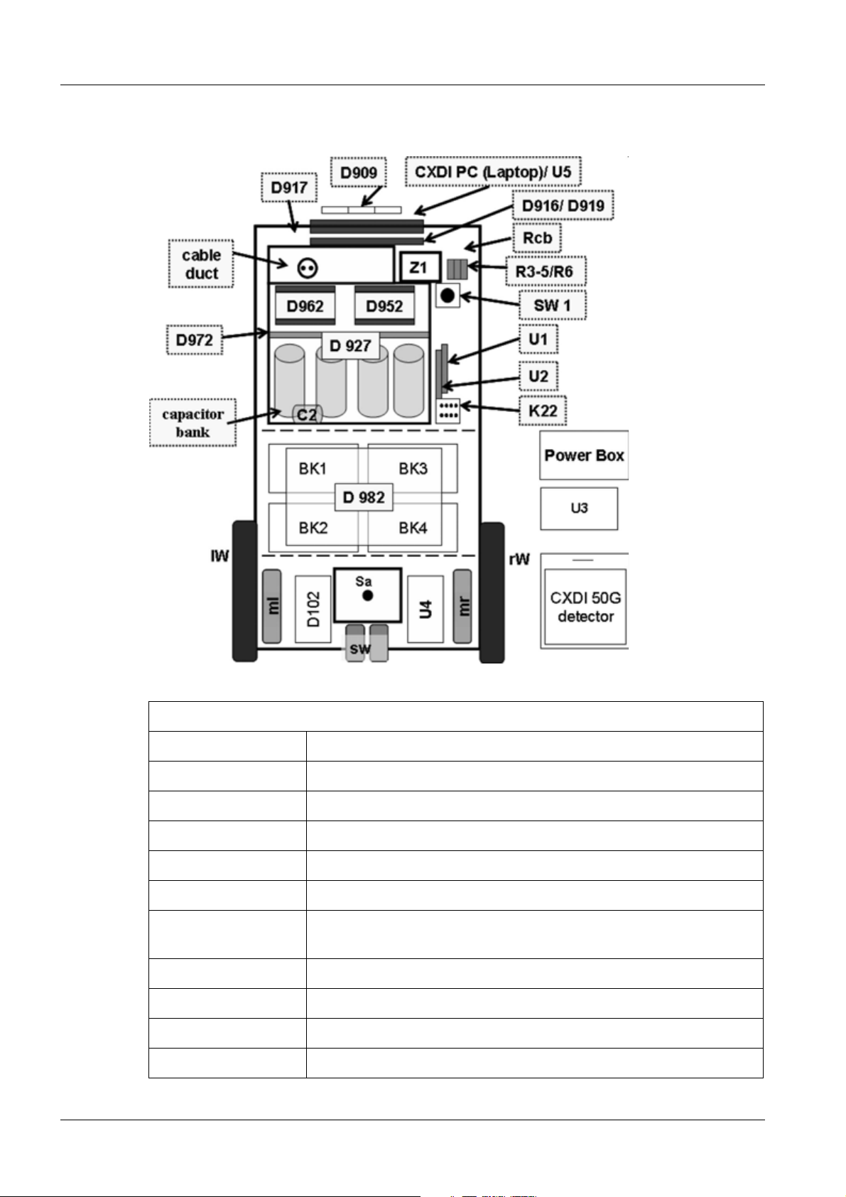
System overview - service 0
Fig. 5: Schematic overview of XP Digital
MOBILETT XP Digital parts
Abbreviations Explanation
D916/D919 CPU board/X-ray interface
D917 Galvanic separation for S27/DAP/remote
Rcb Remote control board (remote control option)
SW1 Key switch, power ON/OFF
Z1 Line filter
C1 (R1) Capacitor for inverter with discharge resistor (front left side / not
shown here)
C2 (R2) Starter capacitor with discharge resistor
R3-R5, R6 (X9) Discharge resistor capacitor bank (front right side)
Capacitor bank 12 x 10 mF capacitors, mounted on D972
K22 Main relay
MOBILETT XP Digital SPR8-230.814.30.03.02 Siemens AG
11.05 CS SD 24
Page 14 of 70
Medical Solutions
Page 15

General 15
D909 X-ray display and keyboard
U1 +5V / ± 15V power supply
U2 +24V power supply
D927 Power supply
D952 Charging board capacitor bank (behind D927)
D962 kV inverter (behind D927)
D972 Capacitor bank board (behind D927)
Sa Support arm adjusting spring
lw/rw/sw Support wheels and back wheels
D982 Battery charger
D102 Motor drive control
BK1 / BK2 Battery block, left
BK3 / BK4 Battery block, right
mr/ml Motor right / motor left
CXDI PC Laptop for the imaging system
CXDI Detector CXDI flat detector
Power box Connecting unit between CXDI PC and CXDI detector
U3 DC converter 300V DC/24V DC
U4 Inverter 24V DC/220V AC
U5 Power supply CXDI PC (laptop)
Optional parts for MOBILETT XP Digital (not shown in illustration)
DAP chamber Dose area product measuring chamber
D991 DAP adapter card (inside the collimator cover)
DAP display DAP display board (in the lower arm segment cover)
Siemens AG SPR8-230.814.30.03.02 MOBILETT XP Digital
Medical Solutions
11.05 CS SD 24
Page 15 of 70
Page 16

16 General
Cleaning 0
• Always disconnect the MOBILETT from the power supply and switch it off before clean-
ing or disinfecting it.
• Never use abrasive cleaners or cleaning agents with solvents (e.g. cleaning solutions,
alcohol or spot removers), since they may damage housing surfaces.
• Do not spray anything on or into the unit.
• Wipe off the MOBILETT with a cloth moistened in water or a diluted, lukewarm solution
of water and dishwashing liquid.
For more information, see the chapter on "Cleaning and disinfection” in the operating
instructions.
MOBILETT XP Digital SPR8-230.814.30.03.02 Siemens AG
11.05 CS SD 24
Page 16 of 70
Medical Solutions
Page 17

General start-up information 17
2General start-up inform ation
3-
Required documents 0
P Check the documents delivered for completeness.
Ring binders containing user documents:
• Operator Manual SPR8-230.621.30..
Ring binders containing technical documents:
• General Safety Information TD00-000.860.01...
• Installation and Start-up SPR8-230.814.30...
• Software Installation SPR8-230.816.30...
• Quality Assurance SPR8-230.820.30...
• Maintenance Protocol SPR8-230.832.01...
• Wiring Diagram SPR8-230.844.30...
• Disposal Instructions SPR8-230.861.30...
• Manufacturer's certificates n.a.
The MOBILETT XP Digital password list can be obtained by accessing the “Knowledgebase” or from the Troubleshooting Guide SPR8-230.840.30...
• MOBILETT XP Digital password list n.a.
The following additional documents are required to configure DICOM Hardcopy:
• General Hardcopy Camera Information SPR8-230.814.40..
Siemens AG SPR8-230.814.30.03.02 MOBILETT XP Digital
Medical Solutions
11.05 CS SD 24
Page 17 of 70
Page 18

18 General start-up information
Required tools, test equipment and aids 0
• Standard service tool kit n.a.
• Measuring device for leakage current and patient
leakage current, e.g.:
51 38 727 Y0766
• Grounding measuring device, e.g.: SECUTEST 44 15 899 RV090
• 2.1 mm precision copper filter or, alternatively,
copper filter set (44 06 120 RV090)
99 00 598RV090
• Dose measuring device, e.g.: PTW DIADOS 97 17 612 Y0388
• Densitometer, e.g.: DensiX-LE 52003 49 51 286Y0388
• Digital multimeter, e.g.: Fluke 8060 A 97 02 101 Y4290
• Centering cross 96 60 051 RE999
• Test phantom, e.g., PTW Normi 13 n.a.
• At least 3 blank writable CDR's n.a.
• Storage oscilloscope (± 2.5 % accuracy) or kV meter.
• Storage oscilloscope (±2.5 % accuracy) or mAs meter.
MOBILETT XP Digital SPR8-230.814.30.03.02 Siemens AG
11.05 CS SD 24
Page 18 of 70
Medical Solutions
Page 19

General start-up information 19
Start-up information 0
• The start-up procedure described here corresponds to a functional test. All adjust-
ments and calibrations are performed at the factory. The MOBILETT XP Digital is ready
for operation on completion of the start-up report.
• The top cover has to be removed to access the CXDI PC or perform measurements on
D916. Place the top cover on a table or similar surface. All cables remain connected.
• The unit can be connected to line voltages of 100-130 V ( ± 10%) or 200-240 V ( ±
10%). The unit automatically adjusts to the existing line voltage.
NOTE
Observe the nominal current of the fuses for the on-site power
connections:
- 15A slow-blow (on-site) for 100-130V ± 10% or
- 15A slow-blow (on-site) for 200-240 V ± 10% line voltage.
The power cable for this device is equipped with a standard safety
plug.
Attach a power plug that is compliant with local standards if necessary.
• Following start-up, country-specific tests must be performed if necessary.
For example:
Acceptance test according to §16 of the X-ray Ordinance (Germany):
Use the measurements in the test certificate provided as the initial values for the required
measurements.
The following values were measured by the manufacturer; refer to the test certificate:
- Brightness of the light localizer
- Filter values (Al equivalent for tube assembly and collimator)
- Coincidence of light field and radiation field
- Accuracy of the tube voltage
- Accuracy of the kV value steps
- Accuracy of the mAs values
- Reproducibility of dose values
• The test/measured values marked by the report icon must be entered in the start-up re-
port located at the end of this manual.
NOTE
Siemens AG SPR8-230.814.30.03.02 MOBILETT XP Digital
Medical Solutions
Recording information immediately during start-up saves time.
Fill in the report form after completing each task.
The start-up report is a component of this documentation.
Page 19 of 70
11.05 CS SD 24
Page 20
20 General start-up information
Information on the protective conductor resistance test 0
Observe the instructions in the "Safety Rules for Installation and Repair"
(ARTD-002.731.17 ...).
The protective conductor resistance of 0.2 ohms must not be exceeded.
Initial measurement
Perform the protective conductor test after completion of all work.
The measurement must be performed according to DIN VDE 0751, Part 1 (see ARTD
Part 2). The protective conductor resistance for all touchable conductive parts must be
measured during the normal operating state of the system.
Make sure that control cables or data cables between the components of the system are
not mistaken for protective conductor connections.
During the measurement, move the power cable and additional connection cables with an
integrated protective conductor section by section to detect cable breaks.
The protective conductor resistance must not exceed 0.2 Ohms.
The values must be recorded as initial measurements, and the measuring points noted, in
the protective conductor resistance report.
The measuring procedure and the measuring device used (designation and serial number) must also be documented.
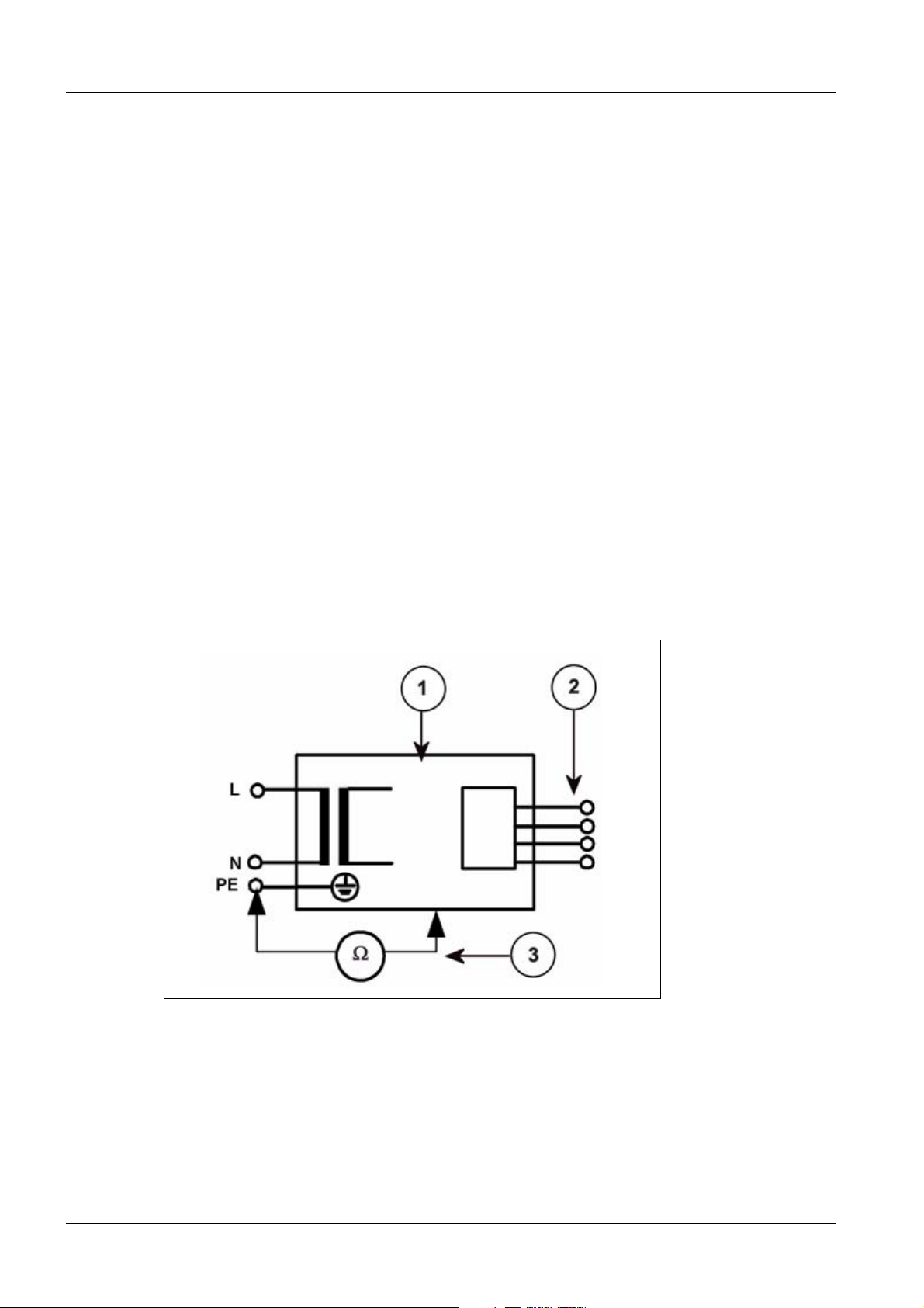
Fig. 6: Measuring circuit for measuring the protective conductor resistance for units that are
disconnected from power, in compliance with DIN VDE 0751-1/2001-10, Fig. C2.
Pos. 1 = System
Pos. 2 = Application part type B (if available)
Pos. 3 = Measurement setup (integrated into measuring device)
Repeat measurement
MOBILETT XP Digital SPR8-230.814.30.03.02 Siemens AG
11.05 CS SD 24
Page 20 of 70
Medical Solutions
Page 21

General start-up information 21
In the case of maintenance or repairs, perform the protective conductor resistance measurement again.
Document and assess the values determined in the repeat measurement.
The measurement must be performed according to DIN VDE 0751, Part 1 (see ARTD
Part 2). The protective conductor resistance for all touchable conductive parts must be
measured during the normal operating state of the system.
Make sure that control cables or data cables between the components of the system are
not mistaken for protective conductor connections.
During the measurement, move the power cable and additional connection cables with an
integrated protective conductor section by section to detect cable breaks.
The protective conductor resistance must not exceed 0.2 Ohms.
The values determined in the repeat measurement must be recorded and assessed, and
the measuring points noted, in the protective conductor resistance report.
The measuring procedure and the measuring device used (designation and serial number) must also be documented.
NOTE
For evaluation purposes, the first measured value and the values
documented during maintenance or safety checks must be compared to the measured values. A sudden or unexpected increase
in the measured values may indicate a defect in the protective conductor connections (protective conductor or contacts) - even if the
limit value of 0.2 ohms is not exceeded.
Siemens AG SPR8-230.814.30.03.02 MOBILETT XP Digital
Medical Solutions
11.05 CS SD 24
Page 21 of 70
Page 22

22 General start-up information
Information on measuring the leakage current 0
Observe the instructions in the "Safety Rules for Installation and Repair"
(ARTD-002.731.17 ...).
WARNING
Electrical voltage!
Non-compliance can lead to severe injury and even death.
¹ The leakage current measurement may be performed on
systems of protection class I only after the protective
conductor test has been passed.
Initial measurement
Perform the leakage current measurement after completion of all work.
Perform the measurement according to DIN VDE 0751, Part 1 (see ARTD-002.731.17....),
and record the determined value as the first measured value.
Measurement of the leakage current according to the differential current method (measurement setup according to (Fig.7/p.22)) must be given preference, since this method
is not dangerous to the person performing the measurement and other persons.
However, please note the minimum resolution of the leakage current measuring device
and any additional manufacturer information restricting the use of the measuring device.
Fig. 7: Measuring circuit for measuring the system leakage current according to the differential
current method in compliance with DIN VDE 0751-1/2001-10, Fig. C6 for protection
class I.
Pos. 1 = System
Pos. 2 = Application part type B (if available)
Pos. 3 = Measurement setup (integrated into measuring device)
MOBILETT XP Digital SPR8-230.814.30.03.02 Siemens AG
11.05 CS SD 24
Page 22 of 70
Medical Solutions
Page 23

General start-up information 23
If the direct measurement of the leakage current is used (measurement setup according
to (Fig.8/p.23)), the system must be insulated during the measurement and must not be
touched.
Fig. 8: Measuring circuit for direct measurement of the system leakage current in compliance
Pos. 1 = System
Pos. 2 = Application part type B (if available)
Pos. 3 = Measurement setup (integrated into measuring device)
with DIN VDE 0751-1/2001-10, Fig. C5 for protection class I.
WARNING
Electrical voltage!
Non-compliance can lead to severe injury and even death.
¹ No housing parts of the system may be touched during
direct measurement of the leakage current (measurement setup according to (Fig.8/p.23)).
¹ Third-person access to the system must be prevented.
The system must be switched on during measurement. Measuring devices with automated measuring sequences must therefore be set to manual measurement.
Enter the highest value as the first measured value in the leakage current report.
This value must not exceed the permissible leakage current values according to DIN VDE
0751-1/2001-10, Table F.1, line "leakage current for devices according to remarks 1 and
3", of 2.5 mA.
Measure and record the current line voltage. If the measured line voltage deviates from
the nominal voltage, correct the measured value to the value corresponding to a measurement at the nominal value of the line voltage. This must also be documented.
Document the measuring procedure (differential measurement or direct measurement)
and the measuring device used (designation and serial number).
Siemens AG SPR8-230.814.30.03.02 MOBILETT XP Digital
Medical Solutions
11.05 CS SD 24
Page 23 of 70
Page 24

24 General start-up information
Repeat measurement
When maintenance or repair work is performed on the primary power supply circuit (e.g.,
repairs to the power-on circuit or replacement of the line filter), the leakage current measurement must be repeated.
The same measuring conditions as in the first measurement apply.
Record and assess the highest value determined in the repeat measurement in the existing system leakage current report.
This value must not exceed the permissible leakage current values according to DIN VDE
0751-1/2001-10, Table F.1, line "leakage current for devices according to remarks 1 and
3", of 2.5 mA.
Measure and record the current line voltage. If the measured line voltage deviates from
the nominal voltage, correct the measured value to the value corresponding to a measurement at the nominal value of the line voltage. This must also be documented.
Document the measuring procedure (differential measurement or direct measurement)
and the measuring device used (designation and serial number).
NOTE
For evaluation purposes, the first measured value and the values
documented during maintenance or safety checks must be compared to the measured values. A sudden or unexpected increase
in the measured values may indicate that a fault has occurred in
the primary power supply circuit (damaged insulation, damage
from moisture, defective interference suppressor, etc.) - even if the
limit value of 2.5 mA is not exceeded.
MOBILETT XP Digital SPR8-230.814.30.03.02 Siemens AG
11.05 CS SD 24
Page 24 of 70
Medical Solutions
Page 25

General start-up information 25
Information on measuring the patient leakage current 0
Observe the instructions in the "Safety Rules for Installation and Repair"
(ARTD-002.731.17 ...).
The patient leakage current must be measured at each application part for systems of
protection class I with type B application parts.)
If the application part has a surface made of non-conductive material, a conductive material (e.g., aluminum foil) must be placed on the surface. The conductive surface must be
large enough to approximate the contact surface of the patient with the application part.
In the case of a flat detector, completely cover the contact surface with aluminum foil.
During the measurement, hold the aluminum foil securely to the application part to be
measured using approx. 0.5 N/cm
2
of pressure.
WARNING
Initial measurement
The patient leakage current must be measured for each application part.
The measurement must be made according to DIN VDE 0751, Part 1 (see
ARTD-002.731.17...).
Electrical voltage!
Non-compliance can lead to severe injury and even death.
¹ The patient leakage current measurement may be per-
formed on systems of protection class I only after the
protective conductor test has been passed.
Fig. 9: Measuring circuit for measurement of the patient leakage current in a type B application
Siemens AG SPR8-230.814.30.03.02 MOBILETT XP Digital
Medical Solutions
11.05 CS SD 24
Page 25 of 70
Page 26

26 General start-up information
part with a protective conductor in compliance with DIN VDE 0751-1/2001-10, Fig. C10.
Pos. 1 = System
Pos. 2 = Application part type B
Pos. 3 = Measurement setup (integrated into measuring device)
The system must be switched on during measurement. Measuring devices with automated measuring sequences must therefore be set to manual measurement.
The determined values, including the application parts/measuring points, must be entered
as the first measured values in the patient leakage current report.
The values for each application part may not exceed the permissible leakage current values according to DIN VDE 0751-1/ 2001-10, table F.1, line "patient leakage current" of
0.01 mA for direct current and 0.1 mA for alternating current.
Document the measuring procedure and the measuring device used (designation and
serial number).
Repeat measurement
When maintenance or repair work capable of affecting the patient leakage current is performed on the system (e.g. repairs to the protective conductor connections, replacement
of parts in the primary power supply circuit, replacement of application parts, technical
changes to application parts), the patient leakage current must be remeasured and documented for each application part.
The same measuring conditions as in the first measurement apply.
The values determined in the repeat measurement, including the application parts/measuring points, must be recorded and assessed in the patient leakage current report.
The values may not exceed the permissible leakage current values according to DIN VDE
0751-1/ 2001-10, table F.1, line "patient leakage current" of 0.01 mA for direct current and
0.1 mA for alternating current.
Document the measuring procedure and the measuring device used (designation and
serial number).
NOTE
For evaluation purposes, the first measured value and the values
documented during maintenance or safety checks must be compared to the measured values. A sudden or unexpected increase
in the measured values may indicate a defect in the system (protective conductor connection damage, insulation damage, damage from moisture, etc.) - even if the limit value of 0.01 mA for
direct current and 0.1 mA for alternating current is not exceeded.
.
MOBILETT XP Digital SPR8-230.814.30.03.02 Siemens AG
11.05 CS SD 24
Page 26 of 70
Medical Solutions
Page 27

Unpacking and visual inspection 27
3Unpacking and visual in spection
4-
Unpacking 0
Fig. 10: Unpacking
• Please follow the unpacking instructions.
• Check the manual movement mode and the hand brake.
Siemens AG SPR8-230.814.30.03.02 MOBILETT XP Digital
Medical Solutions
11.05 CS SD 24
Page 27 of 70
Page 28

28 Unpacking and visual inspection
Visual inspection 0
P • Check the unit for external damage (cracks, breaks, scratches, corrosion etc.).
• Check whether the single tank or the multileaf collimator show any signs of mechanical
defects which might impair the radiation protection.
MOBILETT XP Digital SPR8-230.814.30.03.02 Siemens AG
11.05 CS SD 24
Page 28 of 70
Medical Solutions
Page 29

Unpacking and visual inspection 29
Mechanical function test 0
Cable winch 0
P • Pull out the cable until it is completely unwound.
• Hold the cable with one hand near the duct to slow it down as it is being wound. Pull up
the brake of the cable winch and wind up the cable completely.
This device is equipped with a standard safety plug. Attach a power plug that is compliant
with local standards if necessary.
Support arm movements 0
P • Unlock the support arm. Then check its movements, including several stops. If the DAP
chamber option is included in the delivery, it must be attached to the collimator. The arm
should be easy to move through its full range using one hand and should stop in every
position without any additional movement (up or down).
Fig. 11: Positioning of support arm
Single tank and collimator movements 0
P • Turn the collimator with the handle to the end positions ±90°.
• Rotate the tube to all of its commonly used working and park positions.
Siemens AG SPR8-230.814.30.03.02 MOBILETT XP Digital
Medical Solutions
11.05 CS SD 24
Page 29 of 70
Page 30

30 Checking the shock sensors
4Checking the shock sensors
5-
Checking the shock sensors 0
P Prior to startup, the 4 shock sensors must be checked.
Fig. 12: Shock sensor
If a shock sensor has been activated (colored red), the CXDI detector has to be replaced
before start-up.
• Check the shock sensors.
MOBILETT XP Digital SPR8-230.814.30.03.02 Siemens AG
11.05 CS SD 24
Page 30 of 70
Medical Solutions
Page 31

Start-up 31
5Start-up
6-
Line voltage 0
P The power supply range can vary between 100V AC and 240V AC. Use the DVM to check
the voltage at the socket.
NOTE
The system automatically adjusts to the local line voltage.
Siemens AG SPR8-230.814.30.03.02 MOBILETT XP Digital
Medical Solutions
11.05 CS SD 24
Page 31 of 70
Page 32

32 Start-up
Controls and displays 0
Battery charging operation 0
P The MOBILETT XP Digital is switched off.
Connect the power plug and check whether the AC symbol (~) lights up on the control
panel (4/Fig. 13 / p. 32).
The battery charge status displays must light up. (The batteries are charging)
Exposure operation 0
NOTE
NOTE
At least one of the 3 battery status LEDs must light up for the
checks in exposure operation (3/Fig. 13 / p. 32).
Otherwise, charge the batteries until this operating state is
reached (min. charging time: 2 hrs.).
If the unit has not been used for some time, error ERR13 may appear, indicating a high leakage current at the capacitor bank.
Switch the system off and back on to correct this problem.
If the error persists even after the system has been switched off
and on several times, execute Service Program 1, "Format Capacitor Bank," according to the system troubleshooting instructions.
Fig. 13: Battery status display
• Disconnect the main power cord from the power supply and wind it completely around
the cable spool.
• Switch the unit on. Wait for the initialization process to finish (acoustic signal, KV/mAs
displays visible).
• Check the battery status.
• Switch to manual/analog operation (A/D button on control panel).
• Use the "± kV/± mAs" keys to select different values for KV and mAs.
MOBILETT XP Digital SPR8-230.814.30.03.02 Siemens AG
11.05 CS SD 24
Page 32 of 70
Medical Solutions
Page 33

Start-up 33
P • Check the following functions according to the operator manual:
- Motor drive
- Locking brake
Fig. 14: XP Digital functional check
(1) Power key switch ON/OFF/charge battery
(2) Hand brake
(3) Main power cord
(4) Motor drive - forward/reverse
(5) Brake/release for cable winch
Lead apron holder 0
P Attach the supplied lead apron holder to the support arm joint as needed.
Siemens AG SPR8-230.814.30.03.02 MOBILETT XP Digital
Medical Solutions
11.05 CS SD 24
Page 33 of 70
Page 34

34 Start-up
Fig. 15: Holder
Collimator function 0
P • Completely open the collimator.
• Check the functioning of the light keys on the collimator.
• Check the manual collimations with the light on.
• The light switches off after approx. 20 sec.
• Test the collimator light key on the control panel (1/Fig. 13 / p. 32).
MOBILETT XP Digital SPR8-230.814.30.03.02 Siemens AG
11.05 CS SD 24
Page 34 of 70
Medical Solutions
Page 35

Start-up 35
Calibrating the CXDI detector 0
Start-up of the MOBILETT XP Digital requires a one-time calibration of the CXDI detector.
Four test exposures are performed during this procedure.
Preparation
• Remove the grid (if available).
• Switch the MOBILETT XP Digital on and start the CXDI PC (digital operation)
• Center the CXDI detector with respect to the tube assembly (SID 150 cm).
• Set to maximum collimation
Procedure
Perform the following steps from the user application:
• Select SYSTEM/CALIBRATION.
• Enter the following parameters in the list boxes:
X
P
Exposure data e.g.= exposure = 4; 70KV; 1.8 mAs, SID 150cm
¹ If error messages ("Too much/little dose", "Collimator is used") are displayed
during calibration, the KV and mAs values have to be adjusted accordingly.
NOTE
If the calibration is unsuccessful, check the calibration settings.
The KV and mAs settings may have to be adjusted.
If the calibration continues to be unsuccessful, start the detector
self-test (see Troubleshooting Guide SPR8-230.240.30...) or notify
the Uptime Support Center.
• Check the detector centering. No other objects affecting the calibration may be located
in the beam path.
• Click "START" to begin the calibration.
• Follow the on-screen instructions.
¹ Four exposures are required. No error messages should be displayed. The cali-
bration completion is indicated.
• Use “EXIT” to exit the menu.
• Switch the MOBILETT XP Digital "OFF" and back "ON".
Siemens AG SPR8-230.814.30.03.02 MOBILETT XP Digital
Medical Solutions
11.05 CS SD 24
Page 35 of 70
Page 36

36 Start-up
Exposure release with high voltage 0
NOTE
P
If the “DAP” and/or “Remote Control” options are installed, they
can be tested for proper function during the following tests involving release of X-ray radiation.
Checking the preparation limit time 0
• Select manual/analog operation on the MOBILETT XP Digital control panel (A/D but-
ton).
• Close the collimator and set 60 kV/10 mAs on the control panel.
• The control display for "exposure circuit ready" on the control panel must light up green.
• Set the exposure switch (S27) to preparation and check the "exposure ready" acoustic
signal.
• Hold 'Preparation' and check the preparation limit time of approx. 20 seconds. ERR 25
appears on the display (preparation time without exposure).
• Acknowledge the error with the "collimator light" key on the control panel.
Release an exposure 0
X • Release an exposure.
¹ The radiation indicator on the control panel lights up during the exposure; at the
same time an acoustic signal sounds and the "exposure circuit ready" light on
the control panel goes out.
• "Exposure circuit ready" on the control panel lights up within 15 sec maximum.
Manual exposure termination 0
The user must be able to cancel an exposure at any time.
• Set a midrange kV value (e.g., 70 kV) and the highest possible mAs value.
X
• Release an exposure and interrupt it immediately. "ERR 39" appears on the display and
a succession of brief signal tones (exposure cancelled) sounds. Acknowledge the error
message with the "collimator light" key on the control panel.
MOBILETT XP Digital SPR8-230.814.30.03.02 Siemens AG
11.05 CS SD 24
Page 36 of 70
Medical Solutions
Page 37

Start-up 37
Light field/radiation field 0
Checking the light and radiation field
• Place the detector (35 cm x 43 cm) on the tabletop.
• Set the central beam so it is vertical.
• Set a vertical SID of 100 cm; measure to the upper edge of the detector using the tape
measure in the collimator.
• Switch on the light localizer and set a light field of approx. 30 cm x 30 cm.
• Place the lead ruler (centering cross) centered on the detector.
• Measure the light field and make a note of the dimensions (Fig. 16 / p. 37).
• Position a washer as a side marker.
Fig. 16: Centering cross
• Create a test patient.
• Select an organ program from the "test" range, with approx. 60 kV, 4 mAs.
X
• Release an exposure.
Evaluation: light field to radiation field 0
• Using the centering cross, evaluate on screen, on all four sides, the deviations (A, C
and B, D) between the recorded light field and the radiation field edges (Fig. 17 / p. 38).
Use the zoom function as necessary.
P ¹ The maximum total allowable deviation from the SID is 1.7% (regardless of the
prefix). If the deviation is > 1.7%, the collimator must be adjusted (see the
"Replacement of Parts" instructions).
Siemens AG SPR8-230.814.30.03.02 MOBILETT XP Digital
Medical Solutions
11.05 CS SD 24
Page 37 of 70
Page 38

38 Start-up
Fig. 17: Light field/radiation film
MOBILETT XP Digital SPR8-230.814.30.03.02 Siemens AG
11.05 CS SD 24
Page 38 of 70
Medical Solutions
Page 39

Start-up 39
Configuration of the imaging system 0
P Configure the MOBILETT XP Digital for user setting and network connection according to
the “Software Configuration” chapter of "Software Installation” SPR8-230.816.30....
Siemens AG SPR8-230.814.30.03.02 MOBILETT XP Digital
Medical Solutions
11.05 CS SD 24
Page 39 of 70
Page 40

40 Start-up
Checking the image quality 0
P At start-up, the touch screen display must be checked with the SMPTE test image (bright-
ness and contrast) and the image quality parameters recorded using the quality assur-
ance document SPR8-230.820.30....
File the filled-out quality assurance document in register 9, "Certificates," in the system
binder.
MOBILETT XP Digital SPR8-230.814.30.03.02 Siemens AG
11.05 CS SD 24
Page 40 of 70
Medical Solutions
Page 41

Start-up 41
Options 0
DAP 0
P Measuring device for dose area product (Dose Area Product).
The DAP measuring device is used to measure the kerma area product (kerma = kinetic
energy released in matter) during an X-ray examination. It is primarily used to record the
radiation dose a patient is exposed to.
The DAP is calibrated at the factory:
• Press the test button on the DAP display, a value between 80-120 µGym
2
tion 0.1 µGym
tion 0.01 µGym
If the display is incorrect, the measuring device must be calibrated. See the
"Replacement of Parts" instructions, SPR8-230.841.30...).
) or in the case of a high-resolution chamber, 8-12 µGym2 (DAP resolu-
2
) must be subsequently displayed.
2
(DAP resolu-
X
• Check the function of the DAP display by releasing an exposure. The DAP display
shows a measurement value depending on the object in the beam path.
Remote control 0
P • Adhere the remote control holder to the front right or left side (16/15/Fig. 3 / p. 12).
• Switch on the MOBILETT XP Digital.
X
• Check the "collimator light" and "exposure release" functions of the remote control.
Siemens AG SPR8-230.814.30.03.02 MOBILETT XP Digital
Medical Solutions
11.05 CS SD 24
Page 41 of 70
Page 42

42 DHHS
6DHHS
7-
DHHS tests (USA only) 0
The following tests must be performed and recorded to satisfy the DHHS requirements:
• kV accuracy
• mAs accuracy
• Reproducibility
NOTE
All of the following DHHS checks are performed in manual operation!
MOBILETT XP Digital SPR8-230.814.30.03.02 Siemens AG
11.05 CS SD 24
Page 42 of 70
Medical Solutions
Page 43

DHHS 43
Test of kV accuracy 0
Requirement:
The measured kV values must comply with the limit values specified in the tables. One of
two measuring methods can be used:
1. kV meter procedure:
- kV meter based on the filter comparison technique (e.g. PTW-Nomex). Use the correction factor given in the kV meter operating instructions for non-invasive kV measurements.
2. Oscilloscope method:
- Storage oscilloscope with a measuring accuracy of ± 2.5%
kV meter method: 0
NOTE
The inherent filtration (Al equivalent) of MOBILETT XP Digital is
3.1mm Al (single tank plus collimator).
An installed DAP measurement chamber increases the inherent filtration by 0.4 mm AL.
• Switch the MOBILETT XP Digital on.
• Maintain or switch to manual operation of the MOBILETT XP.
• Prepare the kV meter for the measurement according to the operating instructions.
• Place the measuring detector on a suitable surface and adjust the single tank to the de-
tector using the light localizer (Fig. 18 / p. 44).
• Set the source-to-image distance to the value specified in the kV meter operating in-
structions.
Siemens AG SPR8-230.814.30.03.02 MOBILETT XP Digital
Medical Solutions
11.05 CS SD 24
Page 43 of 70
Page 44

44 DHHS
Fig. 18: kV measurement
X • Set the following exposure parameters and release an exposure after each setting:
kV meter
Selection
DC voltage
* The measuring inaccuracy of the measuring instrument used must be subtracted from
the specified limit values.
P Record the measured values.
Exposure parameters Limit values*
52 kV 50 mAs 49.0 - 55.0 kV
81 kV 20 mAs 77.0 - 85.0 kV
133 kV 12.5 mAs 126.4 - 139.6 kV
Oscilloscope method: 0
"KVS" measuring point for the nominal value and “KV” measuring point for the actual
value. The measuring ratio is 30 kV/V.
• Remove the top cover and place on a table or similar surface. All cables remain con-
nected. Measuring points on CPU D916 (see troubleshooting instructions).
• Connect the oscilloscope to the measuring points of the CPU D916 TP KV, KVS, and
GND (also see the troubleshooting instructions). Oscilloscope setting: Channel 1 = TP
KV 1V/div, channel 2 TP KVS 2V/div, trigger channel 2, trigger stage 2.5 V, 2V/div, 50
ms/div
MOBILETT XP Digital SPR8-230.814.30.03.02 Siemens AG
11.05 CS SD 24
Page 44 of 70
Medical Solutions
Page 45

DHHS 45
• Follow the same procedure as described in “kV meter method”.
Siemens AG SPR8-230.814.30.03.02 MOBILETT XP Digital
Medical Solutions
11.05 CS SD 24
Page 45 of 70
Page 46

46 DHHS
Test of mAs accuracy 0
Requirement:
The measured mAs values must comply with the limit values specified in the tables. One
of two measuring methods can be used:
1. mAs meter method:
- mAs meter (e.g. MAS meter 8160400 with a measuring accuracy of 1% ± 1 digit)
2. Oscilloscope method:
- Storage oscilloscope with a measuring accuracy of ± 2.5%
Oscilloscope method: 0
• Close the collimator.
• Remove the top cover and place on a table or similar surface. All cables remain con-
nected.
• Clamp the oscilloscope to the “JR” and “GND” measuring points on CPU D916.
• Switch the MOBILETT XP Digital on and select manual operation.
• After switching the unit on, wait for approx. 5 minutes to let it stabilize.
Example: Calculation of the mAs value
Fig. 19: mAs calculation
The mAs value can be calculated with the help of the oscilloscope display.
Surface “A” corresponds to the mAs value.
mAs = tube current x exposure time
mAs = 340 mA x 0.006 s = 2.0 mAs
MOBILETT XP Digital SPR8-230.814.30.03.02 Siemens AG
11.05 CS SD 24
Page 46 of 70
Medical Solutions
Page 47

DHHS 47
• Determination for the following exposure parameters (product of tube current x expo-
sure time):
X
Control unit setting
kV mAs
40 5 4,7 - 5,3
81 2 1,9 - 2,1
133 10 9,5 - 10,5
* The measuring inaccuracy of the measuring instrument must be subtracted from the
specified limit values.
P Calculate and record the mAs values.
Allowable mAs value*
mAs meter method: 0
Use of the mAs jumper on PCB D907 directly at the single tank.
• Remove cover from single tank and connect mAs meter to D907 (1/Fig. 20 / p. 47).
• Follow the same procedure as described in “Oscilloscope method”.
For more information on the measuring technique, refer to the user's manual for the
mAs meter.
Fig. 20: mAs jumper D907
Siemens AG SPR8-230.814.30.03.02 MOBILETT XP Digital
Medical Solutions
11.05 CS SD 24
Page 47 of 70
Page 48

48 DHHS
Reproducibility test 0
Requirement:
• The coefficient of variation for the radiation dose for any combination of exposure pa-
rameters does not exceed 0.045. This requires operation at the line voltage compliant
with Siemens specifications.
X
NOTE
Required measuring instrument:
- Dosimeter
Procedure:
In the following test, 10 sequential exposures are taken within one
hour.
The exposure parameters should be temporarily set to different
values following each measurement.
• After switching the system on, wait until its temperature has stabilized. The unit is ready
for these measurements after 15 minutes.
• Release the number of exposures with the specified exposure data:
- 85 kV, 1.0 mAs, 10 exposures.
• Measure the dose for each exposure.
• Reset the display prior to each new measurement.
Calculations: Coefficient of variation C
• For a series of 10 dose measurements, coefficient of variation C is determined using
the following formula:
Fig. 21:
s = Standard deviation resulting from the measurements
_
x = Average measured value of series
x
n = Number of individual measurements in series
Coefficient of variation C must be ≤ 0.045.
Example for determining coefficient of variation C:
Step 1)
= i. measured value of series
i
• 10 exposures with recorded measured values (fictitious values).
MOBILETT XP Digital SPR8-230.814.30.03.02 Siemens AG
11.05 CS SD 24
Page 48 of 70
Medical Solutions
Page 49

DHHS 49
Exposure
(n=10)
Measured values
(xi)
11,01
21,02
31,03
41,04
51,03
61,02
71,02
81,01
91,03
10 1,04
Step 2)
• Addition of measured values:
∑ = 1,01 + 1,02 + 1,03 + 1,04 + 1,03 + 1,02 + 1,02 + 1,01 + 1,03 + 1,04 = 10,25
Calculation of mean value:
Fig. 22:
Step 3)
Calculation of standard deviation:
Fig. 23:
Siemens AG SPR8-230.814.30.03.02 MOBILETT XP Digital
Medical Solutions
11.05 CS SD 24
Page 49 of 70
Page 50

50 DHHS
Fig. 24:
Fig. 25:
Step 4)
P
• Calculation of coefficient:
Fig. 26:
In this example, the generator complies with the specification:
C = 0.0105, which is ≤ 0.0450.
• Perform the described procedure and record the results in the DHHS report.
• Complete the DHHS report.
MOBILETT XP Digital SPR8-230.814.30.03.02 Siemens AG
11.05 CS SD 24
Page 50 of 70
Medical Solutions
Page 51

Backup 51
7Backup
8-
Backup procedure 0
Included with delivery of the MOBILETT XP Digital is a backup of the entire C: driveand D:
drive on the system DVD (factory settings).
P Following start-up of the MOBILETT XP Digital at the customer site and completion of all
adjustment and configuration steps, a second backup operation of the hard drives to CD
is performed.
A "Backup of Configuration" is also created. The "Backup of Configuration" includes all
configuration settings, organ programs, log files, and images from the external storage.
This ensures that the customer configuration can be restored or that the imaging system
can be reinstalled with the customer configuration.
Backup of hard disks 0
Prerequisite
The Mobilett XP Digital has been completely installed and configured according to customer specifications. All checks have been successfully completed.
The MOBILETT XP Digital System DVD is available.
At least 2 blank writable CDs are available (2 blank CDs are included with the delivery).
Delete all test exposures in “local Temp Storage” and in “External Storage” prior to the
backup.
Procedure
• The MOBILETT XP Digital is switched off.
• Open the top cover of the MOBILETT XP Digital and place on a table or similar surface.
All cables remain connected (access to CXDI PC).
• Open the CXDI PC (laptop) to access the keyboard and display. Do NOT switch on the
CXDI PC if it is disconnected from the MOBILETT XP Digital. Otherwise, the display
setting can switch to the default setting without touch screen display on the laptop.
• Label the blank CDs used for the backup with the date and image and number them se-
quentially (min. 2 CDRs required)
• Switch the MOBILETT XP Digital "ON" and place the system DVD in the DVD/RW drive
of the CXDI PC (boot from the system DVD)
NOTE
If necessary, set the boot device to DVD-ROM in the laptop's BIOS.
Access to BIOS: while system is booting, press the F2 key and enter the administrator password "99999".
¹ The display shows the following menu:
- 1 - Backup the complete hard drive (c: + d:)
- 2 - Restore the complete hard drive (c: + d:)
- 3 - Restore factory settings (c: + d:)
- 4 - Back up the complete hard drive (c:)
Siemens AG SPR8-230.814.30.03.02 MOBILETT XP Digital
Medical Solutions
11.05 CS SD 24
Page 51 of 70
Page 52

52 Backup
- 5 - Restore the complete hard drive (c:)
- 6 - Use GHOST interactive
-E - Exit
• Select "1" - Back up the complete hard drive (c: + d:)
¹ Follow the on-screen instructions
¹ The backup completion is displayed
• Remove the CD from the DVD/CD RW drive of the CXDI PC.
• Restart the MOBILETT XP Digital and perform the "Backup of Configuration" as de-
scribed below.
Backup of Configuration 0
The "Backup of Configuration" includes all configuration settings, organ programs, log
files, and images from the external storage and has to be performed following start-up of
the MOBILETT XP Digital at the customer site.
The imaging system service tool is used to back up all relevant data to the D:\_Siemens_
folder. This folder is written to CD using Windows XP Explorer and stored as a backup
CD.
Prerequisites
The system is completely installed and configured according to customer specifications.
All checks have been successfully completed.
At least one blank writable CD is available.
Before backup, delete all test exposures from "external storage."
The CXDI PC is accessible (see “Backup of hard disks” earlier).
The MOBILETT XP Digital is switched on and the application has been launched properly.
Procedure
Perform the following steps from the application:
• Select SYSTEM/ CONFIGURATION/ ADMINISTRATOR SETUP/ SERVICE TOOL.
• Enter the administrator password and confirm with “OK”.
¹ See password list.
• Select “Copy files to _Siemens_” from the SERVICE TOOL menu.
• Select “START”.
¹ Enter the service password (see password list)
• Confirm with “OK”.
¹ All necessary files are copied to the "_Siemens_" directory. Existing data is over-
written.
MOBILETT XP Digital SPR8-230.814.30.03.02 Siemens AG
11.05 CS SD 24
Page 52 of 70
Medical Solutions
Page 53

Backup 53
Writing backup data to CD
After backing up all relevant data to the D:\_Siemens_ folder using the imaging system
service tool, the data in this folder has to be written to CD using Windows XP Explorer.
• Label the blank CD for the backup with the date and "Backup of Configuration" and
number it.
• Select “Explorer” from the SERVICE TOOL menu.
• Start via "START"
¹ Enter the service password (see password list)
• Insert the labeled CD into then CD RW drive of the CXDI PC.
• Copy the “D:\_Siemens_” folder to drive E:\ (CD RW drive).
• Right-click in the right pane of the E:\ drive Explorer window and select "Write these
files to CD".
• Follow the prompts.
¹ The data is saved to CD
• Wait until the write operation is completed.
• Close Explorer.
• Click “Exit” to exit the “SERVICE TOOL”.
• Click “OK” to exit “ADMINISTRATOR SETUP”.
• Switch the MOBILETT XP Digital OFF.
• Close the CXDI PC, secure the CXDI PC transport fastener, and attach the top cover
Siemens AG SPR8-230.814.30.03.02 MOBILETT XP Digital
Medical Solutions
11.05 CS SD 24
Page 53 of 70
Page 54

54 Remaining work
8Remaining work
9-
Final activities 0
Protective conductor test 0
Observe the protective conductor resistance test information in these instructions.
• Perform the protective conductor test with all covers closed in accordance with
ARTD-002.731.17... The protective conductor resistance must not exceed 0.2 Ohms.
P
P
• The values determined must be recorded as initial measurements in the protective con-
ductor resistance report (chapter 11 of these instructions), and the measuring points
must be given.
• The measuring procedure and the measuring device used (designation and serial num-
ber) must also be documented.
Leakage current measurement 0
Observe the leakage current measurement information in these instructions.
• The leakage current must be measured with all covers closed, in accordance with
ARTD-002.731.17... The limit value of 2.5 mA must not be exceeded.
WARNING
• The system must be switched on during measurement. Measuring devices with auto-
mated measuring sequences must therefore be set to manual measurement.
Electrical voltage!
Non-compliance can lead to severe injury and even death.
¹ No housing parts of the system may be touched during
direct measurement of the leakage current .
¹ Third-person access to the system must be prevented.
P
• Enter the highest value as the first measured value in the leakage current report (chap-
ter 11 of these instructions).
• This value must not exceed the permissible leakage current values according to DIN
VDE 0751-1/2001-10, Table F.1, line "leakage current for devices according to remarks 1 and 3", of 2.5 mA.
P
P
• Measure and record the current line voltage. If the measured line voltage deviates from
the nominal voltage, correct the measured value to the value corresponding to a measurement at the nominal value of the line voltage. This must also be documented.
• The measuring procedure (differential measurement or direct measurement) and the
measuring instrument used (designation and serial number) must also be documented.
Patient leakage current measurement 0
Observe the patient leakage current measurement information in these instructions.
• The patient leakage current must be measured with all covers closed, in accordance
with ARTD-002.731.17...
MOBILETT XP Digital SPR8-230.814.30.03.02 Siemens AG
11.05 CS SD 24
Page 54 of 70
Medical Solutions
Page 55

Remaining work 55
• The patient leakage current must be measured at the flat detector.
• The system must be switched on during measurement. Measuring devices with auto-
mated measuring sequences must therefore be set to manual measurement.
P
• Enter the value determined as the first measured value in the patient leakage current
report (chapter 11 of these instructions).
• This value may not exceed the permissible leakage current values according to DIN
VDE 0751-1/ 2001-10, table F.1, line "patient leakage current" of 0.01 mA for direct current and 0.1 mA for alternating current.
P
• The measuring procedure and the measuring device used (designation and serial num-
ber) must also be documented.
Labels 0
Country-specific labeling
P
• The "Warning!" label "This X-ray unit may be dangerous...” is supplied in a number of
languages. Select the correct language and attach the label according to the MOBILETT XP Digital operator manual.
• The "Danger!” label “Explosion hazard...” is supplied in a number of languages. Select
the correct language and attach the label according to the MOBILETT XP Digital operator manual.
• Affix the "Do not open doors to rooms with the unit" label as shown in (Fig. 27 / p. 55).
• For Germany only:
Select the 1.5 m, 2.5 m or 3.5 m "control area" label as required by the customer and
affix it to the bottom of the arm as shown in (Fig. 28 / p. 56).
Fig. 27: "Rambo" label
Siemens AG SPR8-230.814.30.03.02 MOBILETT XP Digital
Medical Solutions
11.05 CS SD 24
Page 55 of 70
Page 56

56 Remaining work
Fig. 28: "Control area" label
Reports 0
• Separate the completed 'Start-up report' (chapter 9 of these instructions) from these in-
structions and file it in the system binder, Register 9, "Certificates."
• Separate the completed DHHS report (chapter 10 of these instructions) from
these instructions and file it in the system binder, Register 9, "Certificates."
• Separate the completed protective conductor resistance report, leakage current report,
and patient leakage current report (chapter 11 of these instructions) from these instructions and file them in the system binder, Register 9, "Certificates."
• Complete the "Installation Protocol" included with the unit and send it (by fax) to the ad-
dress listed in the protocol.
MOBILETT XP Digital SPR8-230.814.30.03.02 Siemens AG
11.05 CS SD 24
Page 56 of 70
Medical Solutions
Page 57

Start-up report 57
9Start-up report
10-
MOBILETT XP Digital 0
This protocol confirms operability according to the datasheet. The original document
remains with the unit, and a copy is filed at the local branch office.
Type / Material No. / Serial No.: ...................................................................................
Customer: ............................................. Customer No.:
........................................................
Check Control point Additional information
❐ Required documents complete
❐ Visual inspection
❐ Cable winch
❐ Support arm movements
❐ Single tank and collimator movements
❐ Shock sensors
❐ Line voltage _________________V
❐ Battery charging operation
❐ Exposure operation
❐ Lead apron holder
❐ Collimator function
❐ Calibrating the CXDI detector
❐ Exposure release with high voltage
❐ Configuration of the imaging system
❐ Light field/radiation field Deviation ≤ ± 1.7%
Options
❐ DAP (test display 80 - 120 µGy m
or 8-12
Display _________ µGym
2
µGym)
2
❐ Remote control
Quality checks
Siemens AG SPR8-230.814.30.03.02 MOBILETT XP Digital
Medical Solutions
11.05 CS SD 24
Page 57 of 70
Page 58

58 Start-up report
❐ Checking the image quality
❐ DHHS checks
Final activities
❐ Backup performed
❐ Protective conductor test
(Measurement values in separate protective conductor resistance report)
❐ Leakage current measurement
(Measurement values in separate leakage current report)
❐ Patient leakage current measurement
(Measurement values in separate patient leakage current report)
❐ Affixing labels
Name: _________________ Date:______________ Signature:__________________
MOBILETT XP Digital SPR8-230.814.30.03.02 Siemens AG
11.05 CS SD 24
Page 58 of 70
Medical Solutions
Page 59

DHHS report 59
10DHHS report
11-
MOBILETT XP Digital 0
The original document remains with the unit, and a copy is filed at the local branch office.
Type / Material No. / Serial No.: ...................................................................................
Customer: ............................................. Customer No.:
........................................................
kV accuracy
Check Control point Check value Additional information
❐ 52 kV / 50 mAs ____________ kV Measuring instrument:
_____________
❐ 81 kV / 20 mAs ____________ kV Serial no.: ______________
❐ 133 kV/12.5 mAs ____________ kV Date of calibration:
_______________________
mAs accuracy
❐ 40 kV / 5 mAs ____________ mAs Measuring instrument:
_____________
❐ 81 kV / 2 mAs ____________ mAs Serial no.: ______________
❐ 133 kV/10 mAs ____________ mAs Date of calibration:
_______________________
Reproducibility
❐ Dose measurement Coefficient of variation C:Measuring instrument:
_____________
___________________ Serial no.: ______________
Date of calibration:
_______________________
Name: _________________ Date:______________ Signature:________________
Siemens AG SPR8-230.814.30.03.02 MOBILETT XP Digital
Medical Solutions
11.05 CS SD 24
Page 59 of 70
Page 60

60 DHHS report
MOBILETT XP Digital SPR8-230.814.30.03.02 Siemens AG
11.05 CS SD 24
Page 60 of 70
Medical Solutions
Page 61

Electrical safety/reports 61
11Electrical safety/reports
12-
Protective conductor resistance/report 0
System: ......................................................................................................................
Material number: ......................................................................................................
Serial number: .........................................................................................................
Customer-spec. Identification number: ..........................................................................
Tab. 1
Protective conductor resistance
First measured value Repeat measurement values
Meas. point 1:
.....................................
Meas. point 2:
.....................................
Meas. point 3:
.....................................
Meas. point 4:
.....................................
Meas. point 5:
.....................................
Meas. point 6:
.....................................
Meas. point 7:
.....................................
Meas. point 8:
.....................................
(*1) Meas. circuit:
Meas. device type:
Meas. device ser. no.:
Meas. device calibrated
up to:
Evaluation: n.a.
Date:
Name:
Signature
(*1) Meas. circuit: See (Fig. 29 / p. 62)
Siemens AG SPR8-230.814.30.03.02 MOBILETT XP Digital
Medical Solutions
11.05 CS SD 24
Page 61 of 70
Page 62

62 Electrical safety/reports
Measuring circuit 0
Fig. 29: Measuring circuit for measuring the protective conductor resistance for units that are
disconnected from power, in compliance with DIN VDE 0751-1/2001-10, Fig. C2.
Pos. 1 Measurement setup (measuring device)
Pos. 2 System
Pos. 3 Application part (if applicable)
Remarks: 0
Tab. 2
Date Comments Name Signature
MOBILETT XP Digital SPR8-230.814.30.03.02 Siemens AG
11.05 CS SD 24
Page 62 of 70
Medical Solutions
Page 63

Electrical safety/reports 63
Leakage current/report 0
System: ...................................................................................................................
Material number: .....................................................................................................
Serial number: .......................................................................................................
Customer-spec. Identification number:
....................................................................................
Tab. 3
Leakage current
First measured value Repeat measurement values
Leakage current
(Highest measured
value) [mA]
Line voltage
during the measurement
[V~]
Leakage current,
Corrected value
[mA]
(*1) Meas. circuit:
Meas. device type:
Meas. device ser. no.:
Measuring device,
calibrated to:
Evaluation:
Date:
Name:
Signature:
(*1) Meas. circuit: See (Fig. 30 / p. 64) through (Fig. 31 / p. 64)
Siemens AG SPR8-230.814.30.03.02 MOBILETT XP Digital
Medical Solutions
11.05 CS SD 24
Page 63 of 70
Page 64

64 Electrical safety/reports
Measuring circuit 0
Direct measurement
Fig. 30: Measuring circuit for direct measurement of the system leakage current in compliance
with DIN VDE 0751-1/2001-10, Fig. C5 for protection class I.
Pos. 1 = System
Pos. 2 = Application part type B (if available)
Pos. 3 = Measurement setup (integrated into measuring device)
Differential measurement
Fig. 31: Measuring circuit for measuring the system leakage current according to the differential
current method in compliance with DIN VDE 0751-1/2001-10, Fig. C6 for protection
class I.
Pos. 1 = System
Pos. 2 = Application part type B (if available)
Pos. 3 = Measurement setup (integrated into measuring device)
MOBILETT XP Digital SPR8-230.814.30.03.02 Siemens AG
11.05 CS SD 24
Page 64 of 70
Medical Solutions
Page 65

Electrical safety/reports 65
Remarks: 0
Tab. 4
Date Comments Name Signature
Siemens AG SPR8-230.814.30.03.02 MOBILETT XP Digital
Medical Solutions
11.05 CS SD 24
Page 65 of 70
Page 66

66 Electrical safety/reports
Date Comments Name Signature
MOBILETT XP Digital SPR8-230.814.30.03.02 Siemens AG
11.05 CS SD 24
Page 66 of 70
Medical Solutions
Page 67

Electrical safety/reports 67
Patient leakage current/report 0
System: ...................................................................................................................
Material number: .....................................................................................................
Serial number: .......................................................................................................
Customer-spec. Identification number:
....................................................................................
Tab. 5
Patient leakage current
First measured value Repeat measurement values
Patient leakage current
1. Application part
...................................
Patient leakage current
2. Application part
...................................
Patient leakage current
3. Application part
...................................
Patient leakage current
4. Application part
...................................
Patient leakage current
5. Application part
...................................
(*1) Meas. circuit:
Meas. device type:
Meas. device ser. no.:
Meas. inst. calibrated
to:
Evaluation:
Date:
Name:
Signature:
(*1) Meas. circuit: See (Fig. 32 / p. 68)
Siemens AG SPR8-230.814.30.03.02 MOBILETT XP Digital
Medical Solutions
11.05 CS SD 24
Page 67 of 70
Page 68

68 Electrical safety/reports
Measuring circuit 0
Fig. 32: Measuring circuit for measurement of the patient leakage current in a type B application
part with a protective conductor in compliance with DIN VDE 0751-1/2001-10, Fig. C10.
Pos. 1 = System
Pos. 2 = Application part type B
Pos. 3 = Measurement setup (integrated into measuring device)
Remarks: 0
Tab. 6
Date Remarks Name Signature
MOBILETT XP Digital SPR8-230.814.30.03.02 Siemens AG
11.05 CS SD 24
Page 68 of 70
Medical Solutions
Page 69

Changes to Previous Version 69
12Changes to Previous Ve rsion
13-
Chapter Section Revision
General start-up information Information on the protec-
New section added
tive conductor resistance
test
General start-up information Information on measuring
New section added
the leakage current
General start-up information Information on measuring
New section added
the patient leakage current
Unpacking and visual inspec-
Unpacking New illustration added.
tion
Remaining work - final tasks Protective conductor test Completely rewritten
Remaining work - final tasks Leakage current measure-
Completely rewritten
ment
Remaining work - final tasks Patient leakage current
New section added
measurement
Remaining work - final tasks Reports Adapted in accordance
with changes
Start-up report n.a. Adapted in accordance
with changes
Electrical safety/reports n.a. New chapter added.
Siemens AG SPR8-230.814.30.03.02 MOBILETT XP Digital
Medical Solutions
11.05 CS SD 24
Page 69 of 70
Page 70

70 Changes to Previous Version
MOBILETT XP Digital SPR8-230.814.30.03.02 Siemens AG
11.05 CS SD 24
Page 70 of 70
Medical Solutions
 Loading...