

Siemens IM 155-6 PN ST User Manual
Manual
IM 155-6 PN ST interface module
(6ES7155-6AU01-0BN0)
Edition
SIMATIC
ET 200SP
04/2017
support.industry.siemens.com

___________________
___________________
___________________
___________________
___________________
___________________
___________________
___________________
___________________
SIMATIC
ET 200SP
IM 155-6 PN ST interface module
(6ES7155-6AU01-0BN0)
Manual
04/2017
A5E03576904
-AE
Preface
Guide
1
Product overview
2
Wiring
3
Parameters/address space
4
Interrupts, diagnostics, error,
and system messages
5
Compatibility
6
Technical specifications
7
Dimension drawing
A
Siemens AG
Division Digital Factory
Postfach 48 48
90026 NÜRNBERG
GERMANY
A5E03576904-AE
Ⓟ
04/2017 Subject to change
Copyright © Siemens AG 2012 - 2017.
All rights reserved
Legal information
Warning notice system
This manual contains notices you have to observe in order to ensure your personal safety, as well as to prevent
damage to property. The notices referring to your personal safety are highlighted in the manual by a safety alert
symbol, notices referring only to property damage have no safety alert symbol. These notices shown below are
graded according to the degree of danger.
DANGER
indicates that death or severe personal injury will result if proper precautions are not taken.
WARNING
indicates that death or severe personal injury may result if proper precautions are not taken.
CAUTION
indicates that minor personal injury can result if proper precautions are not taken.
NOTICE
indicates that property damage can result if proper precautions are not taken.
If more than one degree of danger is present, the warning notice representing the highest degree of danger will
be used. A notice warning of injury to persons with a safety alert symbol may also include a warning relating to
property damage.
Qualified Personnel
The product/system described in this documentation may be operated only by personnel qualified for the specific
task in accordance with the relevant documentation, in particular its warning notices and safety instructions.
Qualified personnel are those who, based on their training and experience, are capable of identifying risks and
avoiding potential hazards when working with these products/systems.
Proper use of Siemens products
Note the following:
WARNING
Siemens products may only be used for the applications described in the catalog and in the relevant technical
documentation. If products and components from other manufacturers are used, these must be recommended
or approved by Siemens. Proper transport, storage, installation, assembly, commissioning, operation and
maintenance are required to ensure that the products operate safely and without any problems. The permissible
ambient conditions must be complied with. The information in the relevant documentation must be observed.
Trademarks
All names identified by ® are registered trademarks of Siemens AG. The remaining trademarks in this publication
may be trademarks whose use by third parties for their own purposes could violate the rights of the owner.
Disclaimer of Liability
We have reviewed the contents of this publication to ensure consistency with the hardware and software
described. Since variance cannot be precluded entirely, we cannot guarantee full consistency. However, the
information in this publication is reviewed regularly and any necessary corrections are included in subsequent
editions.

IM 155-6 PN ST interface module (6ES7155-6AU01-0BN0)
4 Manual, 04/2017, A5E03576904-AE
Preface
Purpose of the documentation
This manual supplements the ET 200SP distributed I/O system
(http://support.automation.siemens.com/WW/view/en/58649293) system manual.
Functions that generally relate to the system are described in this manual.
The information provided in this manual and in the system/function manuals supports you in
commissioning the ET 200SP distributed I/O system.
Conventions
Please also observe notes marked as follows:
Note
A note contains important information on the product described in the documentation, on the
handling of the product or on the section of the documentation to which particular attention
should be paid.
Security information
Siemens provides products and solutions with industrial security functions that support the
secure operation of plants, systems, machines and networks.
In order to protect plants, systems, machines and networks against cyber threats, it is
necessary to implement – and continuously maintain – a holistic, state-of-the-art industrial
security concept. Siemens’ products and solutions only form one element of such a concept.
Customer is responsible to prevent unauthorized access to its plants, systems, machines
and networks. Systems, machines and components should only be connected to the
enterprise network or the internet if and to the extent necessary and with appropriate security
measures (e.g. use of firewalls and network segmentation) in place.
Additionally, Siemens’ guidance on appropriate security measures should be taken into
account. For more information about industrial security, please visit
(http://www.siemens.com/industrialsecurity).
Siemens’ products and solutions undergo continuous development to make them more
secure. Siemens strongly recommends to apply product updates as soon as available and to
always use the latest product versions. Use of product versions that are no longer supported,
and failure to apply latest updates may increase customer’s exposure to cyber threats.
To stay informed about product updates, subscribe to the Siemens Industrial Security RSS
Feed under (http://www.siemens.com/industrialsecurity).

IM 155-6 PN ST interface module (6ES7155-6AU01-0BN0)
Manual, 04/2017, A5E03576904-AE
5
Table of contents
Preface ................................................................................................................................................... 4
1 Guide ...................................................................................................................................................... 6
2 Product overview .................................................................................................................................. 10
2.1 Properties ................................................................................................................................ 10
2.2 Functions ................................................................................................................................ 13
2.2.1 PROFIenergy .......................................................................................................................... 19
2.2.2 Use of fail-safe modules ......................................................................................................... 20
2.2.3 Use of technology modules .................................................................................................... 20
2.2.4 Configuration control (option handling) ................................................................................... 20
3 Wiring ................................................................................................................................................... 21
3.1 Pin assignment ....................................................................................................................... 21
3.2 Schematic circuit diagram ....................................................................................................... 24
4 Parameters/address space ................................................................................................................... 25
4.1 Parameters ............................................................................................................................. 25
4.2 Explanation of parameters ...................................................................................................... 25
4.2.1 Configuration control ............................................................................................................... 25
4.3 Substitute value behavior ....................................................................................................... 26
4.4 Status of the supply voltage L+ of the I/O modules ................................................................ 27
5 Interrupts, diagnostics, error, and system messages ............................................................................. 28
5.1 Status and error displays ........................................................................................................ 28
5.2 Interrupts ................................................................................................................................. 33
5.2.1 Triggering of a diagnostics interrupt ....................................................................................... 33
5.2.2 Triggering a hardware interrupt .............................................................................................. 34
5.2.3 Triggering a swapping interrupt .............................................................................................. 34
5.3 Alarms ..................................................................................................................................... 35
5.3.1 Diagnostics alarms .................................................................................................................. 35
5.3.2 Maintenance events ................................................................................................................ 36
5.3.3 Channel diagnostics................................................................................................................ 37
5.3.4 Invalid configuration states of the ET 200SP on PROFINET IO ............................................ 41
5.3.5 Failure of supply voltage L+ at BaseUnit BU...D .................................................................... 41
5.3.6 STOP of the IO controller and recovery of the IO device ....................................................... 42
6 Compatibility ......................................................................................................................................... 43
7 Technical specifications ........................................................................................................................ 45
A Dimension drawing ............................................................................................................................... 50
IM 155-6 PN ST interface module (6ES7155-6AU01-0BN0)
6 Manual, 04/2017, A5E03576904-AE
1
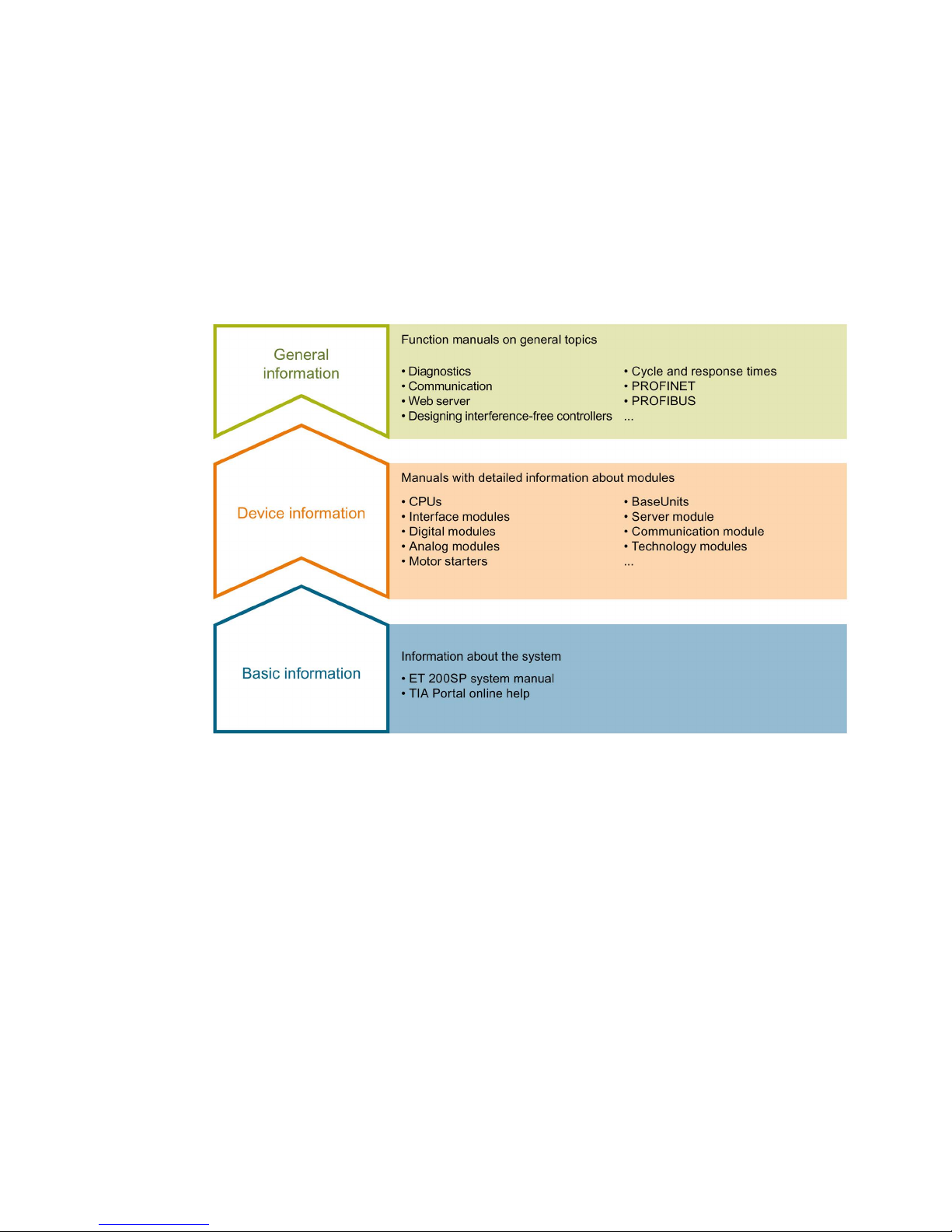
The documentation for the SIMATIC ET 200SP distributed I/O system is arranged into three
areas.
This arrangement enables you to access the specific content you require.
Basic information
The system manual describes in detail the configuration, installation, wiring and
commissioning of the SIMATIC ET 200SP. distributed I/O system. The STEP 7 online help
supports you in the configuration and programming.
Device information
Product manuals contain a compact description of the module-specific information, such as
properties, wiring diagrams, characteristics and technical specifications.

Guide
IM 155-6 PN ST interface module (6ES7155-6AU01-0BN0)
Manual, 04/2017, A5E03576904-AE
7
General information
The function manuals contain detailed descriptions on general topics regarding the SIMATIC
ET 200SP distributed I/O system, e.g. diagnostics, communication, Web server, motion
control and OPC UA.
You can download the documentation free of charge from the Internet
(http://w3.siemens.com/mcms/industrial-automation-systems-simatic/en/manual-
overview/tech-doc-et200/Pages/Default.aspx).
Changes and supplements to the manuals are documented in a Product Information.
You can download the product information free of charge from the Internet
(https://support.industry.siemens.com/cs/us/en/view/73021864).
Manual Collection ET 200SP
The Manual Collection contains the complete documentation on the SIMATIC ET 200SP
distributed I/O system gathered together in one file.
You can find the Manual Collection on the Internet
(http://support.automation.siemens.com/WW/view/en/84133942).
"mySupport"
With "mySupport", your personal workspace, you make the most of your Industry Online
Support.
In "mySupport" you can store filters, favorites and tags, request CAx data and put together
your personal library in the Documentation area. Furthermore, your data is automatically
filled into support requests and you always have an overview of your current requests.
You need to register once to use the full functionality of "mySupport".
You can find "mySupport" in the Internet (https://support.industry.siemens.com/My/ww/en).
"mySupport" - Documentation
In the Documentation area of "mySupport", you have the possibility to combine complete
manuals or parts of them to make your own manual.
You can export the manual in PDF format or in an editable format.
You can find "mySupport" - Documentation in the Internet
(http://support.industry.siemens.com/My/ww/en/documentation).

Guide
IM 155-6 PN ST interface module (6ES7155-6AU01-0BN0)
8 Manual, 04/2017, A5E03576904-AE
"mySupport" - CAx Data
In the CAx Data area of "mySupport", you can have access the latest product data for your
CAx or CAe system.
You configure your own download package with a few clicks.
In doing so you can select:
● Product images, 2D dimension drawings, 3D models, internal circuit diagrams, EPLAN
macro files
● Manuals, characteristics, operating manuals, certificates
● Product master data
You can find "mySupport" - CAx Data in the Internet
(http://support.industry.siemens.com/my/ww/en/CAxOnline).
Application examples
The application examples support you with various tools and examples for solving your
automation tasks. Solutions are shown in interplay with multiple components in the system separated from the focus in individual products.
You can find the application examples on the Internet
(https://support.industry.siemens.com/sc/ww/en/sc/2054).
TIA Selection Tool
With the TIA Selection Tool, you can select, configure and order devices for Totally
Integrated Automation (TIA).
This tool is the successor of the SIMATIC Selection Tool and combines the known
configurators for automation technology into one tool.
With the TIA Selection Tool, you can generate a complete order list from your product
selection or product configuration.
You can find the TIA Selection Tool on the Internet
(http://w3.siemens.com/mcms/topics/en/simatic/tia-selection-tool).

Guide
IM 155-6 PN ST interface module (6ES7155-6AU01-0BN0)
Manual, 04/2017, A5E03576904-AE
9
SIMATIC Automation Tool
You can use the SIMATIC Automation Tool to run commissioning and maintenance activities
simultaneously on various SIMATIC S7 stations as a bulk operation independently of the TIA
Portal.
The SIMATIC Automation Tool provides a multitude of functions:
● Scanning of a PROFINET/Ethernet network and identification of all connected CPUs
● Address assignment (IP, subnet, gateway) and station name (PROFINET device) to a
CPU
● Transfer of the data and the programming device/PC time converted to UTC time to the
module
● Program download to CPU
● Operating mode switchover RUN/STOP
● Localization of the CPU by means of LED flashing
● Reading out CPU error information
● Reading the CPU diagnostic buffer
● Reset to factory settings
● Updating the firmware of the CPU and connected modules
You can find the SIMATIC Automation Tool on the Internet
(https://support.industry.siemens.com/cs/ww/en/view/98161300).
PRONETA
With SIEMENS PRONETA (PROFINET network analysis), you analyze the plant network
during commissioning. PRONETA features two core functions:
● The topology overview independently scans PROFINET and all connected components.
● The IO check is a fast test of the wiring and the module configuration of a system.
You can find SIEMENS PRONETA on the Internet
(https://support.industry.siemens.com/cs/ww/en/view/67460624).
IM 155-6 PN ST interface module (6ES7155-6AU01-0BN0)
10 Manual, 04/2017, A5E03576904-AE
Product overview
2
2.1 Properties
Article number
6ES7155-6AU01-0BN0 (IM 155-6 PN ST interface module and server module)
6ES7155-6AA01-0BN0 (IM 155-6 PN ST interface module with BusAdapter BA 2×RJ45 and
server module)
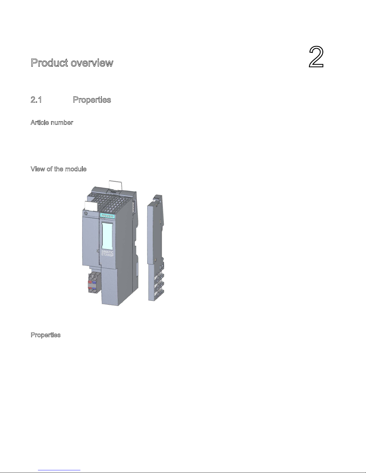
View of the module
Figure 2-1 View of the IM 155-6 PN ST interface module and the server module
Properties
The module has the following technical properties:
● Connects the ET 200SP distributed I/O system with PROFINET IO
● Supply voltage 1L+ 24 V DC (SELV/PELV). The connection plug is included in the scope
of delivery of the interface module.
● PROFINET IO connection via selectable BusAdapter for RJ45 bus connector
(BA 2×RJ45) or for direct connection of the bus cable (BA 2×FC)
● Use of fail-safe modules
● As of firmware version V 3.0, you can plug a light-colored or a dark-colored BaseUnit into
slot 1.
The module supports the following functions (Page 13)

Product overview
2.1 Properties
IM 155-6 PN ST interface module (6ES7155-6AU01-0BN0)
Manual, 04/2017, A5E03576904-AE
11
Maximum configuration
● 32 I/O modules
● 512 bytes I/O data
● 1 m backplane bus (without interface module)
Accessories
The following accessories can be ordered separately:
● BA 2xRJ45 BusAdapter
● BA 2xFC BusAdapter
● 24 V DC connector
● Labeling strips
● Reference identification label
Note
The interface module is also available as a bundle with the BusAdapter BA 2xRJ45 (and the
server module). The article number is 6ES7155
-6AA01-0BN0.
A detailed list of the available accessories can be found in the system manual ET 200SP
distributed I/O system (http://support.automation.siemens.com/WW/view/en/58649293).
Server module
The server module is included in the scope of delivery of the interface module and available
separately as an accessory.
The server module has the following properties:
● Terminates the backplane bus of the ET 200SP distributed I/O system
● Features a holder for 3 spare fuses (5 × 20 mm)
● Identification data I&M 0 to 3
Note
You need to configure and assign parameters to the server module in the configuration
software.
To do this, place the server module in the last configuration slot and enable the parameter
Group diagnostics: Missing supply voltage L+. When there are 32 I/O
modules, the server
module is inserted in slot 33.
You can find more information in the Server module
(http://support.automation.siemens.com/WW/view/en/63257531) manual.

Product overview
2.1 Properties
IM 155-6 PN ST interface module (6ES7155-6AU01-0BN0)
12 Manual, 04/2017, A5E03576904-AE
First BaseUnit of an ET 200SP in the configuration (as of V3.0)
Note
First BaseUnit of an ET 200SP in the configuration
The first BaseUnit of an ET 200SP station may be a dark
-colored one if an AC I/O module or
AI
Energy Meter ST is plugged. Please note the information on limiting the overvoltage and
power rating in the AC I/O module manuals.
A light
-colored BaseUnit must be plugged into the slot of the first 24 V DC I/O module in
order to route the 24
V DC supply voltage via a fuse.
Pay attention to the type of the BaseUnits during the configuration.
As of firmware V3.x, the interface modules support plugging dark-colored BaseUnits in slot
1. This means that modules without a connection to the integrated voltage buses P1 and P2
can now also be configured starting with slot 1. Currently, this applies to the following
modules:
● AI EnergyMeter
● DI 4x120..230VAC ST (6ES7131-6FD00-0BB1)
● DQ 4x24..230VAC/2A ST (6ES7132-6FD00-0BB1)
Requirement for configuration of these modules in slot 1:
● Configuration via GSD or GSDML
● Configuration as of STEP 7 V5.5 SP4 with
– HSP0241 V2.0 for IM155-6 PN ST
– HSP0242 V2.0 for IM155-6 DP HF
– HSP0255 V3.0 for IM155-6 PN HF
● Configuration as of STEP 7 V13 SP1

Product overview
2.2 Functions
IM 155-6 PN ST interface module (6ES7155-6AU01-0BN0)
Manual, 04/2017, A5E03576904-AE
13
2.2
Functions
Introduction
The interface module supports the following PROFINET IO functions:
● Integrated switch with 2 ports
● Supported Ethernet services: ping, arp, network diagnostics (SNMP)/MIB-2, LLDP-MIB
and MRP-MIB
● Port diagnostics
● Disabling ports
● Isochronous real-time communication
● Minimum update time 1 ms
● Prioritized startup
● Media redundancy (MRP)
● Shared device
● Support of submodules on suitable I/O modules
● Module-internal Shared Input/Shared Output (MSI/MSO)
● Device replacement without PG and without topological configuration
● Reset to factory settings via PROFINET IO
● Firmware update via PROFINET IO
● Station extension via ET-Connection
● The BusAdapter provides the connection system for PROFINET IO. The following
versions are available for the IM 155-6 PN ST interface module:
– For standard RJ45 connector: BA 2×RJ45
– For direct connection of the bus cable: BA 2×FC
The interface module supports additional functions:
● Identification data I&M 0 to 3
● PROFIenergy
● Use of fail-safe modules
● Configuration control (option handling)
● Value status (quality information, QI) of I/O modules

Product overview
2.2 Functions
IM 155-6 PN ST interface module (6ES7155-6AU01-0BN0)
14 Manual, 04/2017, A5E03576904-AE
Requirements
The table below shows the software requirements for a configuration with the
IM 155-6 PN ST interface module:
Table 2- 1 Version dependencies of other module functions
Function
Product version
of the module
as of
Firmware version
of the module as
of
Configuration software
Configuration
with GSD file
(http://support.a
utomation.siemens.co
m/WW/view/en/
19698639/1300
00)/software
from a third-
party manufac-
turer 1
STEP 7 as of
V5.5 SP3 with
HSP241
STEP 7
(TIA Portal), as
of V11 SP2
Real-time communication
1
V1.0.0 X X
X
Isochronous real-time com-
munication
1 V1.0.0 X X X
Prioritized startup
1
V1.0.0 X X
X
Device replacement without
programming device
1 V1.0.0 X X X
Media redundancy (MRP)
1
V1.0.0 X X
X
Shared device 1 V1.0.0 X X X (as of V13
SP1)
PROFIenergy
1
V1.0.0
--- X X
Use of fail-safe modules 1 V1.0.1 X X X (as of V13
SP1)
Module-internal Shared In-
put/Shared Output (MSI/MSO)
1 V3.1.0 X X X (as of V13
SP1)
Station extension via ET-
Connection
5 V3.1.0 X X X (as of V13
SP1)
User data 512 bytes 1 V3.1.0 X X X (as of V13
SP1)
Distribution of module channels to multiple submodules
1 V3.3.0 X X (as of V5.5
SP4, HSP0241
V3)
X (as of V13
SP1, Update 6)
Interface module;
article number: 6ES7155-
6AU01-0BN0
1 V4.1 X X (as of V5.5
SP4, HSP241
V4)
X (as of V14
HSP205)
1
Systems of third-party manufacturers: Depending on the range of functions of the third-party system

Product overview
2.2 Functions
IM 155-6 PN ST interface module (6ES7155-6AU01-0BN0)
Manual, 04/2017, A5E03576904-AE
15
Cabling with fixed connection setting
If you set a fixed connection setting of the port in STEP 7, you should also disable
"Autonegotiation/Autocrossover".
You can find more information on this topic in the STEP 7 online help and:
● As of STEP 7 V12, in the PROFINET with STEP 7 V13
(http://support.automation.siemens.com/WW/view/en/49948856) function manual
● As of STEP 7 V5.5, in the system manual PROFINET System Description
(http://support.automation.siemens.com/WW/view/en/19292127)
Isochronous real-time communication
Synchronized transmission method for cyclic exchange of IRT data between PROFINET
devices. A reserved bandwidth within the send clock is available for IRT data. The reserved
bandwidth ensures that the IRT data can also be transferred without being affected by
another high network load (e.g. TCP/IP communication or additional real time
communication) at reserved, chronologically synchronized intervals.
A topological configuration is required for IRT.
Note
IO controller as sync master with IRT communication
We recommend also operating the IO controller as a sync master when configuring the IRT
communication.
Otherwise, IO devices with IRT and RT configuration could fail as a result of sync master
failure.
You can find more information on the configuration of synchronized PROFINET devices in
sync domains in the STEP 7 online help and:
● As of STEP 7 V12, in the PROFINET with STEP 7 V13
(http://support.automation.siemens.com/WW/view/en/49948856) function manual
● As of STEP 7 V5.5, in the system manual PROFINET System Description
(http://support.automation.siemens.com/WW/view/en/19292127)
 Loading...