

Siemens SIMATIC ET 200S, IM 151-7 User Manual
Preface, Contents
SIMATIC
ET 200S
IM 151-7 CPU Interface Module
Manual
No. Designation
1 Product information A5E00385826-02 11/2005
The following supplement is part of this documentation:
Drawing number
Edition
Product Overview
Getting Started
Addressing
ET 200S in the PROFIBUS
Network
ET 200S in the MPI Network
DP Master Module
Commissioning and Diagnostics
Functions of the IM 151-7 CPU
Cycle and Response Times
1
2
3
4
5
6
7
8
9
This manual has the order number:
6ES7151-1AB00-8BA0
Edition 11/2003
A5E00058783-04
Technical Specifications
Changing over from the
IM 151-7 CPU
(6ES7 151-7Ax00-0AB0) to the
IM 151-7 CPU
(6ES7 151-7AA10-0AB0)
Position of the IM 151-7 CPU in
the CPU Range
Glossary, Index
10
11
12

Safety Guidelines
This manual contains notices intended to ensure personal safety, as well as to protect the products and
connected equipment against damage. These notices are highlighted by the symbols shown below and
graded according to severity by the following texts:
Danger
!
indicates that death, severe personal injury or substantial property damage will result if proper precautions
are not taken.
Warning
!
indicates that death, severe personal injury or substantial property damage can result if proper
precautions are not taken.
Caution
!
indicates that minor personal injury can result if proper precautions are not taken.
Caution
indicates that property damage can result if proper precautions are not taken.
Notice
draws your attention to particularly important information on the product, handling the product, or to a
particular part of the documentation.
Qualified Personnel
Only qualified personnel should be allowed to install and work on this equipment. Qualified persons are
defined as persons who are authorized to commission, to ground and to tag circuits, equipment, and
systems in accordance with established safety practices and standards.
Correct Usage
Note the following:
Warning
!
Trademarks
This device and its components may only be used for the applications described in the catalog or the
technical description, and only in connection with devices or components from other manufacturers which
have been approved or recommended by Siemens.
This product can only function correctly and safely if it is transported, stored, set up, and installed
correctly, and operated and maintained as recommended.
SIMATIC, SIMATIC HMI and SIMATIC NET are registered trademarks of SIEMENS AG.
Third parties using for their own purposes any other names in this document which refer to trademarks
might infringe upon the rights of the trademark owners.
Disclaim of LiabilityCopyright W Siemens AG 2003 All rights reserved
The reproduction, transmission or use of this document or its
contents is not permitted without express written authority.
Offenders will be liable for damages. All rights, including rights
created by patent grant or registration of a utility model or
design, are reserved.
Siemens AG
Bereich Automation and Drives
Geschaeftsgebiet Industrial Automation Systems
Postfach 4848, D- 90327 Nuernberg
Siemens Aktiengesellschaft A5E00058783-04
We have checked the contents of this manual for agreement
with the hardware and software described. Since deviations
cannot be precluded entirely, we cannot guarantee full
agreement. However, the data in this manual are reviewed
regularly and any necessary corrections included in
subsequent editions. Suggestions for improvement are
welcomed.
Siemens AG 2003
Technical data subject to change.

Preface
Purpose of the manual
This manual supplements the ET 200S Distributed I/O System manual. It
describes all the functions of the IM 151-7 CPU interface module. The manual
does not deal with general ET 200S functions. You will find these in the ET 200X
Distributed I/O System manual (see also the Section “Integration in the information
landscape”).
The information contained in this manual and in the ET 200S Distributed I/O
System manual will enable you to operate the ET 200S with the IM 151-7 CPU
interface module as an I slave on the PROFIBUS-DP or in an MPI network. The
master functionality in combination with the DP master module is also described.
Required level of knowledge
Knowledge of the field of automation engineering is required to understand the
manual.
Knowledge on how to use computers or other PC equipment (e.g. programming
devices) under the Windows 95/98/2000 and NT operating system is also required.
You should also be familiar with the STEP 7 basic software. Refer to the
”Programming with STEP 7 V5.x” manual.
ET 200S IM 151-7 CPU Interface Module
A5E00058783-04
iii

Preface
Scope of validity of the manual
This manual applies to the interface module IM 151-7 CPU with the order number
6ES7 151-7AA10-0AB0 and to the DP mas ter module with the order num ber
6ES7 138-4HA00-0AB0, as well as to the components of the ET 200S distr ibuted I/O
system specified in the ET 200S Distributed I/O System manual.
This manual contains a description of the components that were valid at the time
the manual was published. We reserve the right to enclose a Product Information
bulletin containing up-to-date information about new components and new versions
of components.
For IM 151-7 CPU with the order number 6ES7 151-7AA00-0AB0 and
IM 151-7 CPU FO with the order number 6ES7 151-7AB00-0AB0, please
download the corresponding manual, ET 200S Interface Module IM 151/CPU from
the Internet:
http://www.siemens.com/automation/service&support
ID 2460607.
This manual is also availabe in the SIMATIC Manual Collection.
Changes compared to the previous version
The following changes/additions have been made since the previous version of the
manual:
The order number or, respectively, the documentation package’s packet
assembly has been changed (see also the section “Integration in the
information landscape”).
Minor changes have been made.
Standards, certificates and approvals
The ET 200S distributed I/O system is based on the IEC 61784-1:2002Ed1 CP 3/1
standard.
The ET 200S distributed I/O system fulfills the requirements and criteria of IEC
61131, Part 2 and the requirements for obtaining the CE marking. The ET 200S
has certificates and approvals for CSA, UL, FM, and shipbuilding.
You will find detailed information on these standards, certificates and approvals in
the ET 200S Distributed I/O System manual.
iv
ET 200S IM 151-7 CPU Interface Module
A5E00058783-04
Position in the information landscape
The following list shows a summary of the documentation packages or manuals:
Preface
ET 200S Distributed I/O
System
6ES7151-1AA10-8xA0
Installing and wiring
the ET 200S
Commissioning and
diagnostics for the
ET 200S
Technical
specifications of the
IM151-1, digital and
analog electronic
modules
Order numbers for
the ET 200S
ET 200S Motor Starters
1
Installing and wiring
motor starters
Commissioning and
diagnostics for motor
starters
Technical
specifications of
motor starters
Order numbers for
motor starters
ET 200S interface module
IM151-7 CPU
6ES7151-1AB00-8xA0
Addressing of the
IM151-7 CPU
ET 200S with IM151-7
CPU in the PROFIBUS
network
Commissioning and
diagnostics for the
IM151-7 CPU
Technical specifications
of the IM151-7 CPU
Automation system
S7-300, list of operations
6ES7398-8AA10-8xN0
1
1
ET 200S
Process-Related
Functions
6ES7151-1AC00-8xA0
1Count 24V/100kHz
1Count 5V/500kHz
1SSI
2PULSE
ET 200S Positioning
1
6ES7151-1AD00-8xA0
1
1STEP 5V/204kHz
1POS INC/Digital
1POS SSI/Digital
1POS INC/Analog
1POS SSI/Analog
..
IM 151-7 CPU
...
Serial interface module ET
200S
6ES7151-1AE00-8xA0
1SI 3964/ASCII
1SI MODBUS/USS
1
x= language designation for order numbers
The documentation packages or manuals can only be ordered in the languages German and English. In addition, the languages French, Spanish and Italian are available in the Internet (see Service & Support in the Internet)
1
ET 200S IM 151-7 CPU Interface Module
A5E00058783-04
v

Preface
Note
The ET 200S fail-safe modules manual is part of the S7 F Systems documentation
package.
Guide to the manual
You can quickly access specific information in the manual by using the following
aids:
At the start of the manual you will find a complete table of contents and a list of
the diagrams and tables that appear in the manual.
An overview of the contents of each section is provided in the left-hand column
on each page of each chapter.
Important technical terminology used in the manual is defined in the Glossary.
At the end of the manual you will find a comprehensive index enabling rapid
access to the information you are looking for.
Language designation for the order numbers of the manuals, e.g.
6ES7151-1AA00-8xA0
x = A = German, B = English
Special note
In addition to the ET 200S manuals, you will also need the manual for the DP
master used and the documentation for the configuration and programming
software used (see the list in Appendix A of the ET 200S Distributed I/O System
manual).
Note
You will find a detailed list of the contents of the ET 200S manuals in Section 1.2
of this manual.
We recommend that you begin by reading this section so as to find out which parts
of which manuals are most relevant to you in helping you to do what you want to
do.
Recycling and disposal
The components of the IM 151-7 CPU contain very few harmful substances which
means that the unit can be recycled.
To ensure environment-friendly recycling and disposal of old equipment, contact an
officially approved disposal company that deals with electronics scrap.
vi
ET 200S IM 151-7 CPU Interface Module
A5E00058783-04

Additional support
Please contact your local Siemens representative if you have any queries about
the products described in this manual.
http://www.siemens.com/automation/partner
Preface
ET 200S IM 151-7 CPU Interface Module
A5E00058783-04
vii

Preface
Training center
We offer training courses to help familiarize you with the ET 200S distributed I/O
system and the SIMATIC S7 programmable controller. Please contact your local
training center or the central training center in
D 90327 Nürnberg.
Telephone: +49 (911) 895-3200
Internet: http://www.sitrain.com
A&D Technical Support
Accessible throughout the world at any time of day:
Johnson City
Nuremberg
Beijing
T echnical Support
Worldwide (Nuremberg)
T echnical Support
Loc. time: 0:00 to 24:00 / 365 days
Teleph.: +49 (0) 180 5050-222
Fax: +49 (0) 1 8 0 5050-223
E-mail: adsupport@
GMT: +1:00
Europe/Africa (Nuremberg)
Authorization
Loc. time: Mon. - Fri. 8:00 to 17:00
Teleph.: +49 (0) 180 5050-222
Fax: +49 (0) 1 8 0 5050-223
E-mail: adsupport@
GMT: +1:00
Technical support and authorization staff generally speak English and German.
siemens.com
siemens.com
United States (Johnson City)
Technical Support and
Authorization
Loc. time: Mon. - Fri. 8:00 to 17:00
Teleph.: +1 (0) 423 262 2522
Fax: +1 (0) 423 262 2289
E-mail: simatic.hotline@
sea.siemens.com
GMT: -5:00
Asia / Australia (Beijing)
Technical Support and
Authorization
Loc. time: Mon. - Fri. 8:00 to 17:00
Teleph.: +86 10 64 75 75 75
Fax: +86 10 64 74 74 74
E-mail: adsupport.asia@
siemens.com
GMT: +8:00
viii
ET 200S IM 151-7 CPU Interface Module
A5E00058783-04

Service & Support on the Internet
In addition to our documentation, we also offer you all of our know-how online on
the Internet.
http://www.siemens.com/automation/service&support
There you will find:
the newsletter, which constantly supplies you with the latest information on your
products
a search function in Service & Support to help you find the documents you need
a forum in which users and specialists can exchange their experiences
worldwide
your local contact partner for Automation & Drives in our contact database
information on on-site service, repairs and spare parts. You will find a lot more
information under ”Services”.
Preface
ET 200S IM 151-7 CPU Interface Module
A5E00058783-04
ix

Preface
x
ET 200S IM 151-7 CPU Interface Module
A5E00058783-04

Contents
1 Preface iii. . . . . . . . . . . . . . . . . . . . . . . . . . . . . . . . . . . . . . . . . . . . . . . . . . . . . . . . . . . . . . . .
2 Product Overview 1-1. . . . . . . . . . . . . . . . . . . . . . . . . . . . . . . . . . . . . . . . . . . . . . . . . . . . . .
1.1 What is the IM 151-7 CPU interface module? 1-2. . . . . . . . . . . . . . . . . . . . . . .
1.2 Guide to the ET 200S manuals 1-5. . . . . . . . . . . . . . . . . . . . . . . . . . . . . . . . . . . .
3 Getting Started 2-1. . . . . . . . . . . . . . . . . . . . . . . . . . . . . . . . . . . . . . . . . . . . . . . . . . . . . . . . .
2.1 1st step: Installing the IM 151-7 CPU (ET 200S) and S7-300 2-3. . . . . . . . . .
2.2 2nd step: Wiring the IM 151-7 CPU (ET 200S) and S7-300 2-4. . . . . . . . . . . .
2.3 3rd step: Commissioning the IM 151-7 CPU (ET 200S) 2-6. . . . . . . . . . . . . . .
2.4 4ht step: Configuring the IM 151-7 CPU for stand-alone operation (MPI) 2-7
2.5 5th step: Programming the IM 151-7 CPU 2-9. . . . . . . . . . . . . . . . . . . . . . . . . .
2.6 6th step: Test Run 2-10. . . . . . . . . . . . . . . . . . . . . . . . . . . . . . . . . . . . . . . . . . . . . . .
2.7 7th step: Upgrading the IM 151-7 CPU as an I slave and commissioning
the S7-300 2-11. . . . . . . . . . . . . . . . . . . . . . . . . . . . . . . . . . . . . . . . . . . . . . . . . . . . .
2.8 8th step: Configuring the IM 151-7 CPU as an I slave and the S7-300
as a DP master 2-12. . . . . . . . . . . . . . . . . . . . . . . . . . . . . . . . . . . . . . . . . . . . . . . . .
2.9 9th step: Programming the IM 151-7 CPU and the
S7-300 CPU 2-16. . . . . . . . . . . . . . . . . . . . . . . . . . . . . . . . . . . . . . . . . . . . . . . . . . . .
2.10 10th step: Commissioning and test run of the IM 151-7 CPU and S7-300 2-19
4 Addressing 3-1. . . . . . . . . . . . . . . . . . . . . . . . . . . . . . . . . . . . . . . . . . . . . . . . . . . . . . . . . . . .
3.1 Slot-Oriented Addressing of the I/O Modules 3-2. . . . . . . . . . . . . . . . . . . . . . . .
3.2 User-oriented addressing of the I/O Modules 3-4. . . . . . . . . . . . . . . . . . . . . . . .
3.3 Data interchanger with the DP Master 3-5. . . . . . . . . . . . . . . . . . . . . . . . . . . . . .
3.4 Accessing the intermediate memory in the IM 151-7 CPU 3-7. . . . . . . . . . . . .
5 ET 200S in the PROFIBUS Network 4-1. . . . . . . . . . . . . . . . . . . . . . . . . . . . . . . . . . . . . .
4.1 ET 200S in the PROFIBUS network 4-2. . . . . . . . . . . . . . . . . . . . . . . . . . . . . . .
4.2 Network components 4-6. . . . . . . . . . . . . . . . . . . . . . . . . . . . . . . . . . . . . . . . . . . .
4.3 PROFIBUS address 4-8. . . . . . . . . . . . . . . . . . . . . . . . . . . . . . . . . . . . . . . . . . . . .
4.4 Functions via the PD/OP 4-9. . . . . . . . . . . . . . . . . . . . . . . . . . . . . . . . . . . . . . . . .
4.5 Direct communication 4-12. . . . . . . . . . . . . . . . . . . . . . . . . . . . . . . . . . . . . . . . . . . .
6 ET 200S in the MPI Network 5-1. . . . . . . . . . . . . . . . . . . . . . . . . . . . . . . . . . . . . . . . . . . . .
5.1 ET 200S in the MPI network 5-2. . . . . . . . . . . . . . . . . . . . . . . . . . . . . . . . . . . . . .
5.2 MPI address 5-3. . . . . . . . . . . . . . . . . . . . . . . . . . . . . . . . . . . . . . . . . . . . . . . . . . . .
ET 200S IM 151-7 CPU Interface Module
A5E00058783-04
xi

Contents
7 DP Master Module 6-1. . . . . . . . . . . . . . . . . . . . . . . . . . . . . . . . . . . . . . . . . . . . . . . . . . . . . .
6.1 Mounting the DP master module 6-2. . . . . . . . . . . . . . . . . . . . . . . . . . . . . . . . . .
6.2 Commissioning the IM 151-7 CPU as a DP master 6-3. . . . . . . . . . . . . . . . . . .
8 Commissioning and Diagnostics 7-1. . . . . . . . . . . . . . . . . . . . . . . . . . . . . . . . . . . . . . . .
7.1 Configuring the IM 151-7 CPU 7-2. . . . . . . . . . . . . . . . . . . . . . . . . . . . . . . . . . . .
7.2 Resetting the memory of the IM 151-7 CPU 7-4. . . . . . . . . . . . . . . . . . . . . . . . .
7.3 Commissioning and startup of the IM 151-7 CPU as an I slave 7-7. . . . . . . .
7.4 Diagnostics using LEDs 7-9. . . . . . . . . . . . . . . . . . . . . . . . . . . . . . . . . . . . . . . . . .
7.5 Diagnostics via diagnostic address with STEP 7 7-12. . . . . . . . . . . . . . . . . . . . .
7.6 Slave diagnostics with IM 151-7 CPU used as an intelligent slave 7-15. . . . . .
7.6.1 Station status 1 to 3 7-16. . . . . . . . . . . . . . . . . . . . . . . . . . . . . . . . . . . . . . . . . . . . .
7.6.2 Master PROFIBUS address 7-18. . . . . . . . . . . . . . . . . . . . . . . . . . . . . . . . . . . . . .
7.6.3 Manufacturer ID 7-18. . . . . . . . . . . . . . . . . . . . . . . . . . . . . . . . . . . . . . . . . . . . . . . . .
7.6.4 Module diagnostics 7-19. . . . . . . . . . . . . . . . . . . . . . . . . . . . . . . . . . . . . . . . . . . . . .
7.6.5 Module status 7-20. . . . . . . . . . . . . . . . . . . . . . . . . . . . . . . . . . . . . . . . . . . . . . . . . . .
7.6.6 Interrupt status 7-22. . . . . . . . . . . . . . . . . . . . . . . . . . . . . . . . . . . . . . . . . . . . . . . . . .
7.7 Diagnostic data of the electronic modules 7-25. . . . . . . . . . . . . . . . . . . . . . . . . . .
7.7.1 Evaluating diagnostic data of the electronic modules in the user
program 7-25. . . . . . . . . . . . . . . . . . . . . . . . . . . . . . . . . . . . . . . . . . . . . . . . . . . . . . . .
7.7.2 Structure and content of the diagnostic data bytes 0 to 7 7-27. . . . . . . . . . . . . .
7.7.3 Channel-specific diagnostic data from byte 8 onwards 7-29. . . . . . . . . . . . . . . .
7.7.4 Example: ET 200S module: 2 AI U (6ES7 134-4FB00-0AB0) each
with diagnostics for channel 0 and 1 7-30. . . . . . . . . . . . . . . . . . . . . . . . . . . . . . .
9 Functions of the IM 151-7 CPU 8-1. . . . . . . . . . . . . . . . . . . . . . . . . . . . . . . . . . . . . . . . . . .
8.1 Data for the PROFIBUS-DP 8-2. . . . . . . . . . . . . . . . . . . . . . . . . . . . . . . . . . . . . .
8.2 The mode selector and LEDs 8-4. . . . . . . . . . . . . . . . . . . . . . . . . . . . . . . . . . . . .
8.3 SIMATIC Micro Memory Card 8-6. . . . . . . . . . . . . . . . . . . . . . . . . . . . . . . . . . . . .
8.4 Memory concept 8-12. . . . . . . . . . . . . . . . . . . . . . . . . . . . . . . . . . . . . . . . . . . . . . . .
8.4.1 Memory areas of the IM 151-7 CPU 8-12. . . . . . . . . . . . . . . . . . . . . . . . . . . . . . .
8.4.2 Memory functions 8-15. . . . . . . . . . . . . . . . . . . . . . . . . . . . . . . . . . . . . . . . . . . . . . .
8.4.3 Address areas 8-20. . . . . . . . . . . . . . . . . . . . . . . . . . . . . . . . . . . . . . . . . . . . . . . . . .
8.4.4 Handling data in DBs 8-23. . . . . . . . . . . . . . . . . . . . . . . . . . . . . . . . . . . . . . . . . . . .
8.4.5 Storing/download entire projects on/from Micro Memory Cards 8-25. . . . . . . .
8.5 Interfaces 8-26. . . . . . . . . . . . . . . . . . . . . . . . . . . . . . . . . . . . . . . . . . . . . . . . . . . . . .
8.6 Clock 8-28. . . . . . . . . . . . . . . . . . . . . . . . . . . . . . . . . . . . . . . . . . . . . . . . . . . . . . . . . .
8.7 S7 connections 8-29. . . . . . . . . . . . . . . . . . . . . . . . . . . . . . . . . . . . . . . . . . . . . . . . .
8.8 Communication 8-34. . . . . . . . . . . . . . . . . . . . . . . . . . . . . . . . . . . . . . . . . . . . . . . . .
8.9 Routing 8-38. . . . . . . . . . . . . . . . . . . . . . . . . . . . . . . . . . . . . . . . . . . . . . . . . . . . . . . .
8.10 Data consistency 8-41. . . . . . . . . . . . . . . . . . . . . . . . . . . . . . . . . . . . . . . . . . . . . . . .
8.11 Blocks 8-42. . . . . . . . . . . . . . . . . . . . . . . . . . . . . . . . . . . . . . . . . . . . . . . . . . . . . . . . .
8.12 Parameters 8-44. . . . . . . . . . . . . . . . . . . . . . . . . . . . . . . . . . . . . . . . . . . . . . . . . . . . .
8.13 Parameterization of the reference junction for the connection
of thermocouples 8-46. . . . . . . . . . . . . . . . . . . . . . . . . . . . . . . . . . . . . . . . . . . . . . . .
ET 200S IM 151-7 CPU Interface Module
xii
A5E00058783-04

Contents
8.14 Removal and insertion of modules during operation 8-48. . . . . . . . . . . . . . . . . .
8.15 Switching power modules off and on during operation 8-51. . . . . . . . . . . . . . . .
10 Cycle and Response Times 9-1. . . . . . . . . . . . . . . . . . . . . . . . . . . . . . . . . . . . . . . . . . . . . .
9.1 Cycle time 9-2. . . . . . . . . . . . . . . . . . . . . . . . . . . . . . . . . . . . . . . . . . . . . . . . . . . . . .
9.2 Response time 9-5. . . . . . . . . . . . . . . . . . . . . . . . . . . . . . . . . . . . . . . . . . . . . . . . . .
9.3 Interrupt response time 9-8. . . . . . . . . . . . . . . . . . . . . . . . . . . . . . . . . . . . . . . . . .
11 Technical Specifications 10-1. . . . . . . . . . . . . . . . . . . . . . . . . . . . . . . . . . . . . . . . . . . . . . . .
10.1 Technical specifications of the IM 151-7 CPU 10-2. . . . . . . . . . . . . . . . . . . . . . .
12 Changing IM 151-7 CPU (6ES7 151-7Ax00..) to IM 151-7 CPU
(6ES7 151-7AA10-0AB0) 11-1. . . . . . . . . . . . . . . . . . . . . . . . . . . . . . . . . . . . . . . . . . . . . . . . .
13 Position of the IM 151-7 CPU in the CPU Range 12-1. . . . . . . . . . . . . . . . . . . . . . . . . . .
12.1 Differences to selected S7-300 CPUs 12-2. . . . . . . . . . . . . . . . . . . . . . . . . . . . . .
12.2 Porting the user program 12-3. . . . . . . . . . . . . . . . . . . . . . . . . . . . . . . . . . . . . . . . .
Glossary Glossary-1. . . . . . . . . . . . . . . . . . . . . . . . . . . . . . . . . . . . . . . . . . . . . . . . . . . . . . . . . .
Index Index-1. . . . . . . . . . . . . . . . . . . . . . . . . . . . . . . . . . . . . . . . . . . . . . . . . . . . . . . . . . . . . . .
ET 200S IM 151-7 CPU Interface Module
A5E00058783-04
xiii

Contents
Figures
1-1 View of the ET 200S distributed I/O system with the IM 151-7 CPU
and the DP master module 1-3. . . . . . . . . . . . . . . . . . . . . . . . . . . . . . . . . . . . . . .
1-2 Components and the manuals required for them 1-5. . . . . . . . . . . . . . . . . . . . .
1-3 Components and the manuals required for them (continued) 1-6. . . . . . . . . .
2-1 Installing the IM 151-7 CPU (ET 200S) 2-3. . . . . . . . . . . . . . . . . . . . . . . . . . . . .
2-2 Illustration showing the S7-300 2-5. . . . . . . . . . . . . . . . . . . . . . . . . . . . . . . . . . . .
3-1 Structure of the default address area 3-2. . . . . . . . . . . . . . . . . . . . . . . . . . . . . . .
3-2 Slots on the ET 200S 3-2. . . . . . . . . . . . . . . . . . . . . . . . . . . . . . . . . . . . . . . . . . . .
3-3 Example of address assignment for I/O modules 3-4. . . . . . . . . . . . . . . . . . . .
3-4 Structure of the address area for user-oriented addressing 3-4. . . . . . . . . . . .
3-5 Principles of data transfer between the DP master and the ET 200S
with the IM 151-7 CPU 3-5. . . . . . . . . . . . . . . . . . . . . . . . . . . . . . . . . . . . . . . . . . .
4-1 Example of a PROFIBUS network 4-2. . . . . . . . . . . . . . . . . . . . . . . . . . . . . . . . .
4-2 Setting the mode of the DP interface at the IM 151-7 CPU 4-3. . . . . . . . . . . .
4-3 The PD/OP accesses the ET 200S via the DP interface in the
DP master 4-5. . . . . . . . . . . . . . . . . . . . . . . . . . . . . . . . . . . . . . . . . . . . . . . . . . . . . .
4-4 The PD directly accesses the ET 200S 4-5. . . . . . . . . . . . . . . . . . . . . . . . . . . . .
4-5 Connecting the DP network 4-7. . . . . . . . . . . . . . . . . . . . . . . . . . . . . . . . . . . . . . .
4-6 Principle behind forcing 4-10. . . . . . . . . . . . . . . . . . . . . . . . . . . . . . . . . . . . . . . . . .
4-7 Direct communication with the IM 151-7 CPU 4-12. . . . . . . . . . . . . . . . . . . . . . .
5-1 Example of an MPI network 5-2. . . . . . . . . . . . . . . . . . . . . . . . . . . . . . . . . . . . . . .
6-1 Example of the structure with the IM 151-7 CPU acting as the
DP master 6-1. . . . . . . . . . . . . . . . . . . . . . . . . . . . . . . . . . . . . . . . . . . . . . . . . . . . . .
6-2 Mounting the DP master module 6-2. . . . . . . . . . . . . . . . . . . . . . . . . . . . . . . . . .
7-1 How to use the mode selector to reset the memory 7-5. . . . . . . . . . . . . . . . . .
7-2 Diagnostic addresses for the DP master and ET 200S 7-12. . . . . . . . . . . . . . . .
7-3 Format of the slave diagnostic data 7-15. . . . . . . . . . . . . . . . . . . . . . . . . . . . . . . .
7-4 Structure of the module diagnosis for the IM 151-7 CPU 7-19. . . . . . . . . . . . . .
7-5 Structure of the module status 7-21. . . . . . . . . . . . . . . . . . . . . . . . . . . . . . . . . . . .
7-6 Structure of the interrupt status 7-22. . . . . . . . . . . . . . . . . . . . . . . . . . . . . . . . . . . .
7-7 Byte y+4 to y+7 for the diagnostic interrupt (changed operating
status of the intelligent slave) 7-23. . . . . . . . . . . . . . . . . . . . . . . . . . . . . . . . . . . . .
7-8 Byte y+4 to y+7 for diagnostic interrupt (SFB 75) 7-24. . . . . . . . . . . . . . . . . . . .
7-9 Structure of the diagnostic data using a 4 channel mixed module
as an example 7-26. . . . . . . . . . . . . . . . . . . . . . . . . . . . . . . . . . . . . . . . . . . . . . . . . .
7-10 Bytes 0 and 1 of the diagnostic data 7-27. . . . . . . . . . . . . . . . . . . . . . . . . . . . . . .
7-11 Bytes 4 to 7 of the diagnostic data 7-28. . . . . . . . . . . . . . . . . . . . . . . . . . . . . . . . .
7-12 Single fault of a channel 7-29. . . . . . . . . . . . . . . . . . . . . . . . . . . . . . . . . . . . . . . . . .
8-1 Mode selector 8-4. . . . . . . . . . . . . . . . . . . . . . . . . . . . . . . . . . . . . . . . . . . . . . . . . .
8-2 Position of the memory card slot for the MMC on the IM 151-7 CPU 8-9. . . .
8-3 Memory areas of the IM 151-7 CPU 8-12. . . . . . . . . . . . . . . . . . . . . . . . . . . . . . .
8-4 Load and working memory 8-15. . . . . . . . . . . . . . . . . . . . . . . . . . . . . . . . . . . . . . . .
8-5 Processing steps within a cycle 8-21. . . . . . . . . . . . . . . . . . . . . . . . . . . . . . . . . . .
8-6 Handling recipe data 8-23. . . . . . . . . . . . . . . . . . . . . . . . . . . . . . . . . . . . . . . . . . . . .
8-7 Handling measured value archives 8-24. . . . . . . . . . . . . . . . . . . . . . . . . . . . . . . . .
8-8 Routing gateway 8-39. . . . . . . . . . . . . . . . . . . . . . . . . . . . . . . . . . . . . . . . . . . . . . . .
8-9 Routing – TeleService application example 8-40. . . . . . . . . . . . . . . . . . . . . . . . . .
8-10 Example of a parameterization dialog box for the CPU module
parameters in STEP 7 V5.2 + SP1 8-47. . . . . . . . . . . . . . . . . . . . . . . . . . . . . . . . .
9-1 Component parts of the cycle time 9-2. . . . . . . . . . . . . . . . . . . . . . . . . . . . . . . . .
9-2 Shortest response time 9-6. . . . . . . . . . . . . . . . . . . . . . . . . . . . . . . . . . . . . . . . . .
9-3 Longest response time 9-7. . . . . . . . . . . . . . . . . . . . . . . . . . . . . . . . . . . . . . . . . . .
10-1 Basic circuit diagram for the IM 151-7 CPU 10-4. . . . . . . . . . . . . . . . . . . . . . . . .
12-1 Example: FB with unpacked addresses 12-3. . . . . . . . . . . . . . . . . . . . . . . . . . . . .
xiv
ET 200S IM 151-7 CPU Interface Module
A5E00058783-04

Contents
12-2 Example: FB with packed addresses 12-4. . . . . . . . . . . . . . . . . . . . . . . . . . . . . . .
12-3 Example: Rewiring the signals 12-5. . . . . . . . . . . . . . . . . . . . . . . . . . . . . . . . . . . .
ET 200S IM 151-7 CPU Interface Module
A5E00058783-04
xv

Contents
Tables
1-1 Limitations in the use of ET 200S modules 1-2. . . . . . . . . . . . . . . . . . . . . . . . . .
1-2 Topics of the manuals in the ET 200S manual package 1-7. . . . . . . . . . . . . . .
3-1 Addresses of the ET 200S I/O modules 3-3. . . . . . . . . . . . . . . . . . . . . . . . . . . .
3-2 Accessing the address areas 3-7. . . . . . . . . . . . . . . . . . . . . . . . . . . . . . . . . . . . .
3-3 Addressing interface in STEP 7 V5.1 (extract) 3-8. . . . . . . . . . . . . . . . . . . . . . .
4-1 Behavior of the IM 151-7 CPU depending on the DP interface setting 4-4. . .
4-2 Network components 4-6. . . . . . . . . . . . . . . . . . . . . . . . . . . . . . . . . . . . . . . . . . . .
6-1 Event recognition of the IM 151-7 CPU as a DP master 6-5. . . . . . . . . . . . . . .
7-1 Configuration options 7-2. . . . . . . . . . . . . . . . . . . . . . . . . . . . . . . . . . . . . . . . . . . .
7-2 Ways to reset the memory 7-4. . . . . . . . . . . . . . . . . . . . . . . . . . . . . . . . . . . . . . . .
7-3 Internal CPU events at memory resetting 7-5. . . . . . . . . . . . . . . . . . . . . . . . . . .
7-4 LED display for PROFIBUS-DP (IM 151-7 CPU is an I slave) 7-10. . . . . . . . . .
7-5 LED display for PROFIBUS-DP (IM 151-7 CPU is a master) 7-11. . . . . . . . . .
7-6 Responses to operating mode changes and interruptions in user data
transfer in the DP master and the ET 200S with the IM 151-7 CPU
as an I slave 7-13. . . . . . . . . . . . . . . . . . . . . . . . . . . . . . . . . . . . . . . . . . . . . . . . . . . .
7-7 Evaluation of RUN-STOP transitions in the DP master/ ET 200S with
IM 151-7 CPU as the I slave 7-14. . . . . . . . . . . . . . . . . . . . . . . . . . . . . . . . . . . . . .
7-8 Structure of station status 1 (byte 0) 7-16. . . . . . . . . . . . . . . . . . . . . . . . . . . . . . .
7-9 Structure of station status 2 (byte 1) 7-17. . . . . . . . . . . . . . . . . . . . . . . . . . . . . . .
7-10 Structure of station status 3 (byte 2) 7-17. . . . . . . . . . . . . . . . . . . . . . . . . . . . . . .
7-11 Structure of the master PROFIBUS address (byte 3) 7-18. . . . . . . . . . . . . . . . .
7-12 Structure of the manufacturer identification (bytes 4 and 5) 7-18. . . . . . . . . . . .
7-13 Identifiers of the module classes 7-27. . . . . . . . . . . . . . . . . . . . . . . . . . . . . . . . . . .
8-1 Attributes from the device database (DDB) file 8-2. . . . . . . . . . . . . . . . . . . . . .
8-2 Positions of the mode selector 8-4. . . . . . . . . . . . . . . . . . . . . . . . . . . . . . . . . . . .
8-3 LEDs for CPU functionality 8-5. . . . . . . . . . . . . . . . . . . . . . . . . . . . . . . . . . . . . . .
8-4 Available MMCs 8-7. . . . . . . . . . . . . . . . . . . . . . . . . . . . . . . . . . . . . . . . . . . . . . . . .
8-5 Firmware update with MMC 8-10. . . . . . . . . . . . . . . . . . . . . . . . . . . . . . . . . . . . . . .
8-6 Backing up the operating system 8-11. . . . . . . . . . . . . . . . . . . . . . . . . . . . . . . . . .
8-7 Retentive behavior of the memory objects 8-14. . . . . . . . . . . . . . . . . . . . . . . . . .
8-8 Retentive behavior of the DBs in IM 151-7 CPU 8-14. . . . . . . . . . . . . . . . . . . . .
8-9 Address areas of the system memory 8-20. . . . . . . . . . . . . . . . . . . . . . . . . . . . . .
8-10 Connecdevices 8-27. . . . . . . . . . . . . . . . . . . . . . . . . . . . . . . . . . . . . . . . . . . . . . . . .
8-11 Features of the clock 8-28. . . . . . . . . . . . . . . . . . . . . . . . . . . . . . . . . . . . . . . . . . . .
8-12 Distribution of the S7 connections 8-32. . . . . . . . . . . . . . . . . . . . . . . . . . . . . . . . .
8-13 Availability of the S7 connections 8-33. . . . . . . . . . . . . . . . . . . . . . . . . . . . . . . . . .
8-14 Communication utilities of the IM 151-7 CPU 8-34. . . . . . . . . . . . . . . . . . . . . . . .
8-15 GD resources of the IM 151-7 CPU 8-37. . . . . . . . . . . . . . . . . . . . . . . . . . . . . . . .
8-16 Overview of the blocks 8-42. . . . . . . . . . . . . . . . . . . . . . . . . . . . . . . . . . . . . . . . . . .
8-17 Parameter blocks, setparameters and their ranges for the
IM 151-7 CPU 8-44. . . . . . . . . . . . . . . . . . . . . . . . . . . . . . . . . . . . . . . . . . . . . . . . . .
8-18 Parameterization of the reference junction 8-46. . . . . . . . . . . . . . . . . . . . . . . . . .
8-19 Result of the preset/actual comparison in modules that cannot be
parameterized 8-49. . . . . . . . . . . . . . . . . . . . . . . . . . . . . . . . . . . . . . . . . . . . . . . . . .
8-20 Result of the preset/actual comparison in the case of parameterizable
modules with the power module switched on 8-49. . . . . . . . . . . . . . . . . . . . . . . .
8-21 Result of the preset/actual comparison in the case of parameterizable
modules with the power module switched off 8-50. . . . . . . . . . . . . . . . . . . . . . . .
9-1 Operating system processing time in the scan cycle checkpoint 9-3. . . . . . . .
9-2 Process image updating 9-3. . . . . . . . . . . . . . . . . . . . . . . . . . . . . . . . . . . . . . . . . .
9-3 Dependency of the user program scanning time 9-4. . . . . . . . . . . . . . . . . . . . .
9-4 Extending the cycle by nesting interrupts 9-4. . . . . . . . . . . . . . . . . . . . . . . . . . .
9-5 Interrupt response times of the IM 151-7 CPU (without communication) 9-8.
xvi
ET 200S IM 151-7 CPU Interface Module
A5E00058783-04

Contents
10-1 Terminal assignment for the interface module IM 151-7 CPU 10-3. . . . . . . . . .
10-2 Pin assignment of the DP master module 10-3. . . . . . . . . . . . . . . . . . . . . . . . . . .
12-1 Differences to selected S7-300 CPUs 12-2. . . . . . . . . . . . . . . . . . . . . . . . . . . . . .
12-2 Example : Replacements under Tools ! Rewire 12-4. . . . . . . . . . . . . . . . . . . . . .
ET 200S IM 151-7 CPU Interface Module
A5E00058783-04
xvii

Contents
xviii
ET 200S IM 151-7 CPU Interface Module
A5E00058783-04

Product Overview
In this chapter
The product overview provides information about
The role of the IM 151-7 CPU interface module within the ET 200S distributed
I/O system.
Which manuals in the ET 200S manual package contain what information.
Chapter overview
1
In
Section
1.1 What is the IM 151-7 CPU interface module? 1-2
1.2 Guide to the ET 200S manuals 1-5
Contents Page
ET 200S IM 151-7 CPU Interface Module
A5E00058783-04
1-1

Product Overview
1.1 What is the IM 151-7 CPU interface module?
What is the IM 151-7 CPU?
The IM 151-7 CPU is a component of the ET 200S distributed I/O system with
degree of protection IP 20. The IM 151-7 CPU interface module is an ”intelligent
pre-processing unit” (I slave). It enables you to decentralize control tasks.
An ET 200S with an IM 151-7 CPU can therefore exercise full and, if necessary,
independent control over a process-related functional unit and can be used as a
stand-alone CPU. The IM 151-7 CPU also features DP master functionality in
combination with the DP master module. The use of the IM 151-7 CPU leads to
further modularization and standardization of process-related functional units and
simple, clear machine concepts.
How is the IM 151-7 CPU integrated in the ET 200S?
The IM 151-7 CPU interface module is integrated in the ET 200S in the same way
as any other module. In other words, its configuration concept, installation and
expansion capability are the same.
Limitations in the use of ET 200S modules
The following modules can be used with the IM 151-7 CPU as of the version
specified here:
Table 1-1 Limitations in the use of ET 200S modules
Module
1COUNT 24V/100kHz 6ES7 138-4DA03-0AB0 01 07/2002
1COUNT 5V/500kHz 6ES7 138-4DE01-0AB0 01 07/2002
1SSI 6ES7 138-4DB01-0AB0 01 07/2002
EM 1STEP 5V/204kHz 6ES7 138-4DC00-0AB0 04 04/2001
1 SI 3964/ASCII 6ES7 138-4DF00-0AB0 02 08/2000
1SI MODBUS/USS 6ES7 138-4DF10-0AB0 02 06/2002
2AI U HF 6ES7 134-4LB00-0AB0 03 03/2001
2AI I 2/4WIRE HF 6ES7 134-4MB00-0AB0 02 02/2000
2AO U HF 6ES7 135-4LB01-0AB0 01 11/2002
Order number As of product
version
Product
release
1-2
ET 200S IM 151-7 CPU Interface Module
A5E00058783-04

View
Product Overview
The figure below shows a sample configuration of an ET 200S with an
IM 151-7 CPU.
Interface module
IM 151-7 CPU
DP master module
PM-E power module
for electronic modules
Electronic modules
Power module for the
PM-D motor starter
Direct-on-line starter
Reversing starter
Terminating module
TM-E terminal
modules for elec-
TM-P terminal
modules for
power modules
Figure 1-1 View of the ET 200S distributed I/O system with the IM 151-7 CPU and the DP master
module
tronic modules
Power bus
ET 200S IM 151-7 CPU Interface Module
A5E00058783-04
1-3

Product Overview
Features of the IM 151-7 CPU compared to other modules
The IM 151-7 CPU interface module has the following special features:
The interface has PLC functionality (integrated CPU component with 48 kByte
working memory).
The interface module can only be operated with fitted load memory (MMC).
The interface module can be enhanced with up to 63 I/O modules from the
ET 200S range.
The interface module has a mode selector with positions for RUN, STOP and
MRES.
There are 6 LEDs on the front of the interface module to indicate the following:
– ET 200S faults (SF)
– Bus faults (BF)
– Supply voltage for electronic components (ON)
– Force requests (FRCE)
– Operating mode of the IM 151-7 CPU (RUN and STOP)
Connection to the PROFIBUS-DP via RS 485
In combination with the DP master module, the IM 151-7 CPU can be used as a
DP master.
How is the ET 200S configured with the IM 151-7 CPU?
To configure the ET 200S with IM 151-7 CPU (configuration and parameterization),
you will need the configuration software STEP 7
as of V5.1 + Service Pack 4 for IM 151-7 CPU as an I slave
as of V5.2 + Service Pack 1 for DP master functionality
(IM 151-7 CPU with DP master module)
How to configure the ET 200S with IM 151-7 CPU is described in Chapters 7.1 and
6.2 of this manual.
How is the IM 151-7 CPU programmed?
To program the IM 151-7 CPU, you will need the configuration software STEP 7
as of V5.1 + Service Pack 4 for IM 151-7 CPU as an I slave
as of V5.2 + Service Pack 1 for DP master functionality
(IM 151-7 CPU with DP master module)
1-4
The Instruction list contains the STEP 7 instruction set for programming the
IM 151-7 CPU.
ET 200S IM 151-7 CPU Interface Module
A5E00058783-04
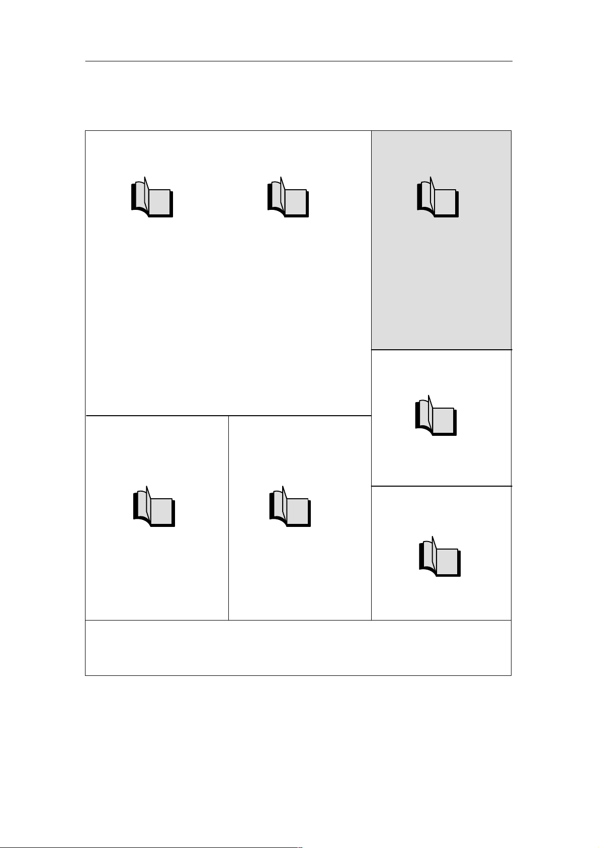
1.2 Guide to the ET 200S manuals
They utilize the following components ...
The components of ET 200S are described in various manuals. They are parts of
various documentation packages. The figure below shows possible configuration
variants of the ET 200S and the necessary manuals in the documentation
packages.
Product Overview
The ET 200S consists of the
following components:
IM151-1
IM151-1
IM151-1
PM-E
PM-E
PM-E
2 AI
2DO
2DO
1SSI
2DO
1PosInc/Digital
2 AO
2PULSE
1PosInc/Analog
You will require the information contained in the following manuals:
ET 200S Distributed
I/O System
ET 200S Distributed
I/O System
+
ET 200S Process-Related Functions
ET 200S Distributed
I/O System
+
ET 200S Positioning
Order numbers for
the necessary documentation pakkages or manuals
6ES7 151-1AA10-8xA0
6ES7 151-1AA10-8xA0
6ES7 151-1AC00-8xA0
6ES7 151-1AA10-8xA0
6ES7 151-1AD00-8xA0
ET 200S Distributed
I/O System
IM151-1
PM-E
2DO
2 AI
Modbus/USS
+
ET 200S Serial Interface
Module
ET 200S Distributed
I/O System
IM151-7
CPU
PM-E
2DO
2 AI
2 AO
+
IM151-7/CPU Interface Module
Figure 1-2 Components and the manuals required for them
ET 200S IM 151-7 CPU Interface Module
A5E00058783-04
6ES7 151-1AA10-8xA0
6ES7 151-1AE00-8xA0
6ES7 151-1AA10-8xA0
6ES7 151-1AB00-8xA0
1-5
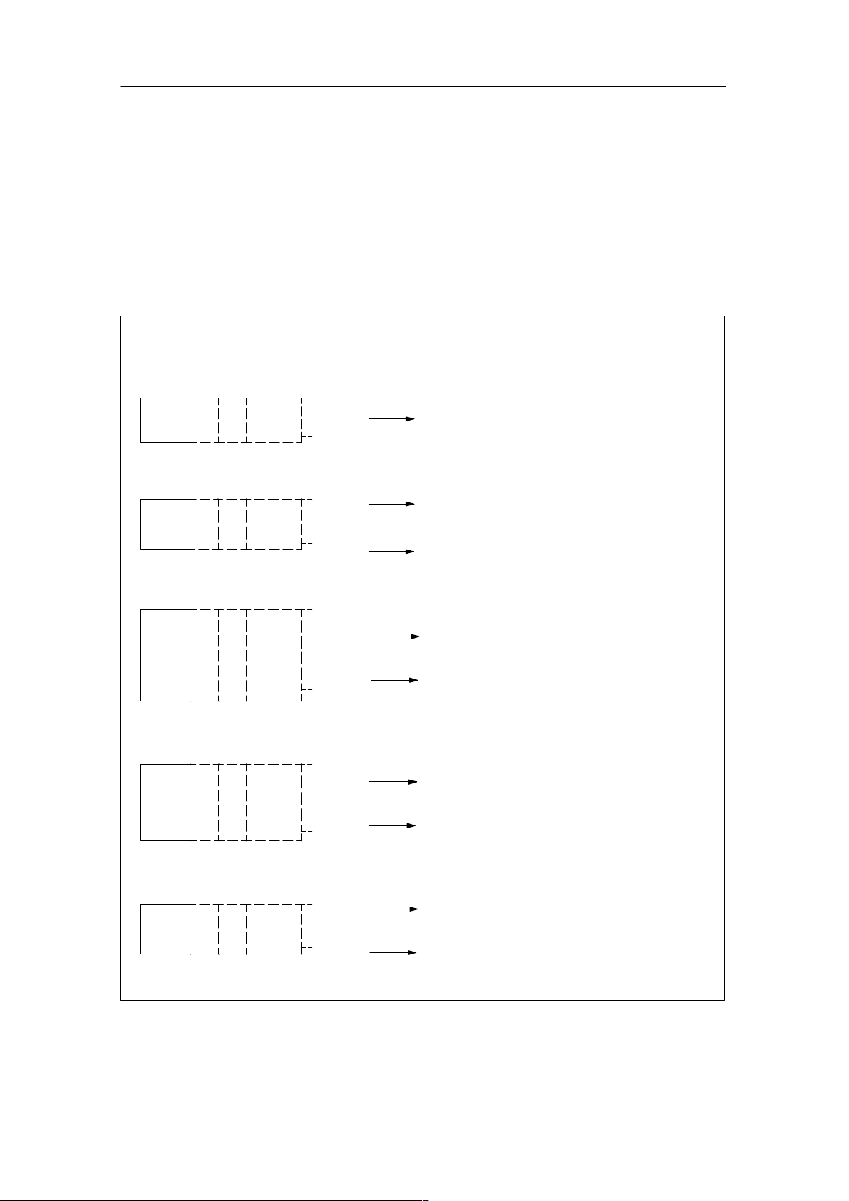
Product Overview
The ET 200S consists of the
following components:
P
IM 151
IM151-1
IM151-1
PM-E
PM-E
2DO
2DO
2 AO
2DO
M
PM-D
PM-E
DS DS
F-DI
F-DO
You will require the information contained in
the following manuals:
ET 200S Distributed
I/O System
+
ET 200S Motor Starters
ET 200S Safety-Integra-
ted SIGUARD System
ET 200S Distributed I/O
System
+
ET 200S Distributed I/O System, Fail-Safe Modules manual in the
documentation packages:
S7 F Systems and
S7 Distributed Safety
Order numbers for
the necessary documentation pakkages or manuals
6ES7 151-1AA10-8xA0
6ES7 151-1AA10-8xA0
6ES7 988-8FA10-8xA0
6ES7 988-8FB10-8xA0
ET 200S Distributed I/O
System
+
PM-E
IM151-1
F DI
F DO
F-DS 1 e-x
F-DS 1e-x
ET 200S Distributed I/O System, Fail-Safe Modules ma-
PM-D F PROFIsafe
nual in the
documentation packages:
S7 F Systems and
S7 Distributed Safety
+
ET 200S Motor Starters
Fail-Safe Motor Starters
Safety-Integrated SIGUARD
Figure 1-3 Components and the manuals required for them (continued)
6ES7 151-1AA10-8xA0
6ES7 988-8FA10-8xA0
6ES7 988-8FB10-8xA0
6ES7 151-1AA10-8xA0
1-6
ET 200S IM 151-7 CPU Interface Module
A5E00058783-04

Product Overview
Where do you find what information?
The following table will help you find the information you require quickly. It tells you
which manual you need to refer to and which section deals with the topic you are
interested in.
Table 1-2 Topics of the manuals in the ET 200S manual package
Manual
Description
Serial interface
Interface Module
IM 151-7 CPU
Technological
Functions ET 200S
Positioning
Distributed I/O
System ET 200S
ET 200S Motor Starter
Fail-Safe Motor Starter
ET 200S components 1 1 1 2 2 2
Configuration
possibilities
Communication 4
Configuration 3 7 3
Addressing 2 5
Installation 2 4 5
Electrical configuration
and wiring of the ET
200S
Programming 8 5
Commissioning and
diagnostics
Functions 5
General technical
specifications
Technical specifications 6 2-5 2 2,3
Terminal modules 5, 9,
Power modules 6, 9-11 10
Direct starters and soft
starters
Reversible starters 8
Safety-integrated
ET 200S SIGUARD
Interface module 8
Electronic modules 11-15
1 3 4 3 3 1
5 6
3 6 7
4 7 8
9
11
7
9
ET 2200S
Module ET 200S
Safety-integrated
Distributed I/O System
ET 200S fail-safe modules
System description
S7 Distributed Safety
Configuring and programming
ET 200S IM 151-7 CPU Interface Module
A5E00058783-04
1-7

Product Overview
Table 1-2 Topics of the manuals in the ET 200S manual package
Manual
Description
Serial interface
Functions ET 200S
Positioning
ET 2200S
Distributed I/O
System ET 200S
ET 200S Motor Starter
Positioning module 3-6
Expansion module 10
Fail-safe modules 11 9
Monitoring, cycle and
reaction times
Order numbers A A 11
Dimension drawings B B 10
Applications C
Glossary Gl Gl Gl 13 10 9
Interface Module
Fail-Safe Motor Starter
7 12 9
Technological
IM 151-7 CPU
Module ET 200S
Distributed I/O System
Safety-integrated
ET 200S fail-safe modules
System description
S7 Distributed Safety
Configuring and programming
The frame for configuration and parameter assignment for the IM 151-7 CPU can be found on the Internet at
http://www.ad.siemens.de/simatic-cs
ET 200S fail-safe modules
You can find the ET 200S Distributed I/O System, Fail-Safe Modules manual
in the S7 F Systems (order number 6ES7 988-8FA10-8xA0) documentation
package and in the S7 Distributed Safety documentation package (order number
6ES7 988-8FB10-8xA0).
1-8
ET 200S IM 151-7 CPU Interface Module
A5E00058783-04

Getting Started
Introduction
This guide takes you through the 10 commissioning steps required to set up a
functioning IM 151-7 CPU application by running through a concrete example. In
this way, you will get to know the basic functions of your IM 151-7 CPU for the
following:
Hardware and software
Stand-alone operation (MPI)
Intelligent DP slave (PROFIBUS-DP)
Prerequisites
You must be familiar with the fundamentals of electronic/electrical engineering and
have experience of working with computers and Microsoft Windows
95/98/NT/2000.
2
Danger
!
Chapter overview
The IM 151-7 CPU, the ET 200S and the S7-300 are used in installations and
systems that require you to comply with specific rules and regulations that vary
depending on the application.
Please note the relevant safety and accident prevention regulations, such as
IEC 204 (emergency stop systems).
Non-compliance with these regulations can result in serious injury and damage to
both machinery and equipment.
In
Section
2.1 1st step: Installing the IM 151-7CPU (ET 200S) and S7-300 2-3
2.2 2nd step: Wiring the IM 151-7 CPU (ET 200S) and S7-300 2-4
2.3 3rd step: Commissioning the IM 151-7 CPU (ET 200S) 2-6
2.4 4th step: Configuring the IM 151-7 CPU for stand-alone operation
2.5 5th step: Programming the IM 151-7 CPU 2-9
2.6 6th step: Test Run 2-10
2.7 7th step: Changing the IM 151-7 CPU to an I slave and
Contents Page
2-7
(MPI)
2-11
commissioning of the S7-300
ET 200S IM 151-7 CPU Interface Module
A5E00058783-04
2-1

Getting Started
In
Section
2.8 8th step: Configuring the IM 151-7 CPU as an I slave and the
S7-300 as a DP master
2.9 9th step: Programming the IM 151-7 CPU and the S7-300-CPU 2-16
2.10 10th step: Commissioning and test run of the IM 151-7 CPU and
S7-300
PageContents
2-12
2-19
Required material and tools
Quantity
1 S7-300 system, consisting of power supply (PS), CPU with
1 Power supply (PS), e.g. PS 307 with power connection cable
1 IM 151-7 CPU with terminating module e.g. 6ES7 151-7AA10-0AB0
1 SIMATIC Micro Memory Card (MMC) e.g. 6ES7 953-8LL00-0AA0
1 Power module (PM) e.g. 6ES7 138-4CA00-0AA0
1 Digital input module (DI) e.g. 6ES7 131-4BD00-0AA0
1 Digital output module (DO) e.g. 6ES7 132-4BD00-0AA0
1 Terminal module (TM) for the PM e.g. 6ES7 193-4CC30-0AA0
2 Terminal modules for DI and DO e.g. 6ES7 193-4CB30-0AA0
1 Mounting rail for the ET 200S various
1
1 PROFIBUS-DP cable various
1 Screwdriver with tip width 3 mm commercially available
1 Screwdriver with tip width 4.5 mm commercially available
1 Diagonal cutting pliers and tools for wire stripping commercially available
1 Tool for pressing on wire end ferrules commercially available
approx.
2 m
4 1-pin ON button (24 V) commercially available
Article Order number (SIEMENS)
various
DP interface (here: CPU 315 2-DP), digital input module (DI)
in slot 4 and digital output module (DO) in slot 5, incl.
mounting rail, bus connectors and cabling
e.g. 6ES7 307-1EA00-0AA0
(optional)
Programming device (PD) with PROFIBUS-DP interface,
installed software STEP 7 Version ≥5.1 and PD cable (up to
1.5 MBit/s)
Stranded wire with 1 mm2 cross section with appropriate wire
end ferrules, type A, length 6 mm and 12 mm
various
commercially available
2-2
ET 200S IM 151-7 CPU Interface Module
A5E00058783-04
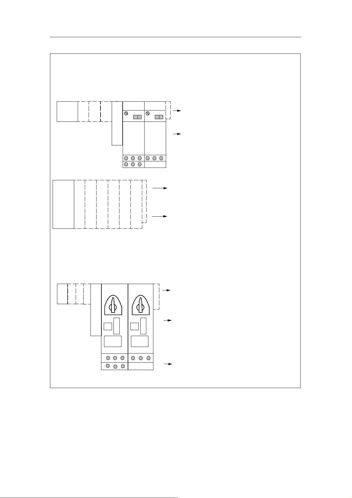
Getting Started
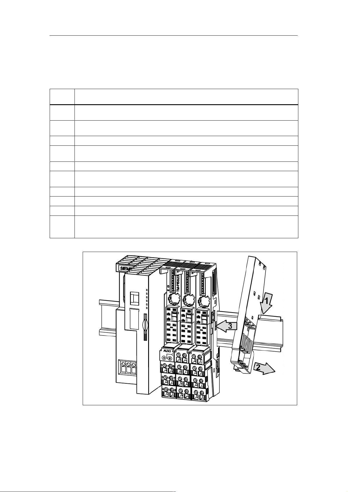
2.1 1st step: Installing the IM 151-7 CPU (ET 200S) and S7-300
Se-
Description
quence
1 Install the S7-300 as described in Installation Manual for Automation System S7-300, Setting
Up.
2 If you want to operate the IM 151-7 CPU using a dedicated power supply, hang the PS in the
mounting rail of the S7-300 and push in until it engages.
3 Hang the IM 151-7 CPU in the mounting rail and push in until it engages.
4 Hang the TM for the PM in the mounting rail to the right of the IM 151-7 CPU and push in until
it engages.
5 Push the TM to the left until it engages audibly in the IM 151-7 CPU.
6 Repeat points 3 and 4 for two TMs for the electronics modules and finally for the terminating
module (does not engage in the mounting rail).
7 Push the PM into the appropriate TM until it engages.
8 Push the DI into the free TM on the left until it engages.
9 Push the DO into the last free TM until it engages.
10 Insert the micro memory card into the IM 151-7 CPU (must be installed otherwise the system
will not work). A micro memory card with unknown content should be erased beforehand at the
programming device.
Figure 2-1 Installing the IM 151-7 CPU (ET200S)
ET 200S IM 151-7 CPU Interface Module
A5E00058783-04
FRCE
RUN
STOP
SF
BF
ON
2-3

Getting Started
2.2 2nd step: Wiring the IM 151-7 CPU (ET 200S) and S7-300
Sequence
1 Wire the S7-300 as described in Installation Manual for Automation System S7-300, Setting
2 Lengthen the connections for each of the 4 buttons using a cable. Strip 6 mm of insulation
3 At the DI of the S7-300, connect each of the inputs 1.1 (terminal 13) and 1.2 (terminal 14) to
4 Connect the two remaining 1-pin buttons to the DI of the ET 200S as follows:
Description
Up.
from the free cable ends and cap the ends with wire end ferrules.
L+ on the PS of the S7-300 using a button.
connect one button to terminals 1 and 3
connect the other button to terminals 5 and 7
Note regarding spring terminals
Releasing the spring of a connection: Insert a screwdriver with 3 mm tip as far as it will go into
the upper round hole of the terminal, pulling the screwdriver handle upwards slightly if
necessary. A free cable end can then be inserted into the square hole below. Pull the
screwdriver back out again and check that the cable is fitted securely.
5 Wire terminal 2 on the TM of the PM to L+ of the PS and terminal 3 on the TM of the PM to M
of the PS. The ends of the cables to be connected must be stripped by 11 mm and capped
with wire end ferrules.
6 Wire terminal 1L+ of the IM 151-7 CPU to L+ of the PS and terminal 1M of the IM151-7 CPU
to M of the PS.
Note
The ends of the cables to be connected must be stripped by 11 mm and capped with wire
end ferrules.
The PS of the S7-300 can also be used to supply power to the IM 151-7 CPU and to the
PM.
7 Connect the PD and IM 151-7 CPU to the PD cable and tighten all connectors.
8 Connect the PS of the ET 200S, the PS of the S7-300 and the PD to the mains power supply
system.
2-4
ET 200S IM 151-7 CPU Interface Module
A5E00058783-04
 Loading...