

Siemens ILP-1, ILPT-1 Installation Instructions Manual
Installation Instructions
Models ILP-1/ILPT-1
Fire Safety
These instructions are written in accordance with the
installation guidelines of NFPA 72, National Fire Alarm
Code, and CAN/ULC-S524, The Installation of Fire
Alarm Systems.
CAUTION: Detector Device Storage
DO NOT install this detection device until all
construction is completed.
DO NOT store this detection device where it can
be contaminated by dirt, dust, or humidity.
DETECTOR PLACEMENT
Although no specific spacings are set for the detectors
used for a clean air application, use 30 foot center
spacing (900 sq ft) from NFPA Standard 72 Chapter 5
and CAN/ULC-S524, if practical, as a guide or starting
point for a detector installation layout. This spacing,
however, is based on ideal conditions - smooth ceiling,
no air movement, and no physical obstructions. In
some applications, therefore, considerably less area
is protected adequately by each smoke detector. This
is why it is mandatory to closely follow the installation
drawings. In all installations place the detector on the
ceiling, a minimum of 6 inches from a side wall, or on
a wall, 6 inches from the ceiling.
If you have any questions regarding detector
placement, follow the drawings provided or approved
by Siemens Building Technologies, Inc. or by its
authorized distributors. This is extremely important!
The detector placements shown on these drawings
were chosen after a careful evaluation of the area that
is protected. Factors such as air currents, temperature,
humidity, pressure, and the nature of the load were
carefully considered. Especially noted were the room
or area configuration and the type of ceiling (sloped
or flat, smooth or beamed). Siemens Building
Technologies, Inc.'s extensive experience in the design
of the system assures the best detector placement by
following these drawings. Sound engineering
judgement by qualified personnel must be followed.
To avoid nuisance alarms:
Do not locate the detector next to an oil burner, electric
heaters, kitchens, or garages where exhaust fumes
can trigger an alarm. Other causes of false alarms
are dust accumulation, heavy concentrations of steam,
heavy pipe or cigar smoking, high relative humidity
or other humid areas where condensation may
occur, and concentrated aerosol sprays.
AIR CURRENTS
Before a detector can sense a fire, the products of
combustion or smoke must travel from the fire to the
detector. This travel is especially influenced by air
currents; therefore, consider air movement when
designing the system. While combustion products tend
to rise, drafts from hallways, air diffusers, fans, etc.,
may help or hinder the travel of combustion products
Siemens Building Technologies, Inc.
8 Fernwood Road
Florham Park, New Jersey 07932
P/N 315-092594-8
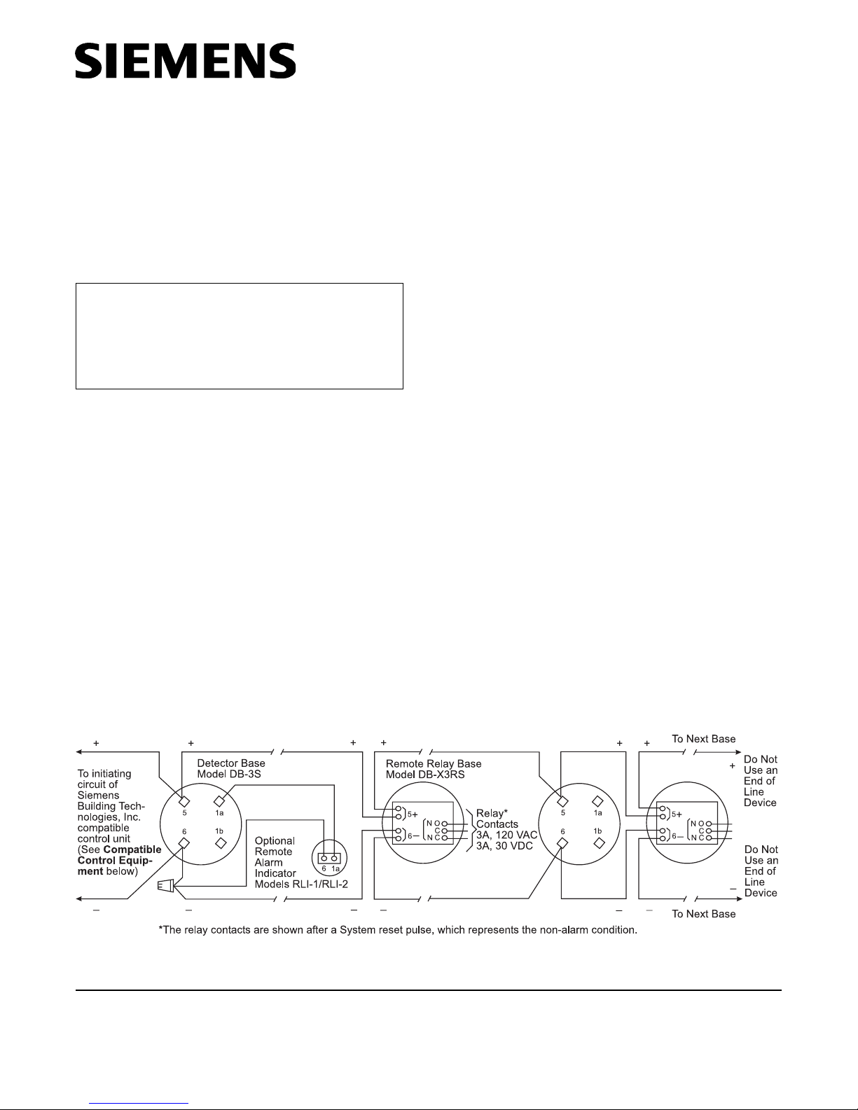
Figure 1
Installation and Wiring Diagram
Siemens Building Technologies, Ltd.
2 Kenview Boulevard
Brampton, Ontario L6T 5E4 CN
to the detector. When positioning a detector at a
particular location, give consideration to windows and
doors, both open and closed, to ventilating systems,
both in and out of operation, and to other factors
influencing air movement. Do not install a detector in
the air stream of a room air supply diffuser. It is better
to position a detector closer to an air return.
The distance that products of combustion or smoke
travel from a fire to the detector is not usually the
shortest linear route. Combustion products or smoke
usually rise to the ceiling, then spread out. Average
ceiling heights of 8 to 10 feet do not abnormally affect
detector response. High ceilings, located in churches,
warehouses, auditoriums, etc., do affect detector
response and should be considered.
SPECIAL CEILING CONSTRUCTION FACTORS
Ceiling obstructions can change the natural movement
of air and combustion products. Depending on the
direction of smoke travel, joists and beams can slow
the movement of heated air and smoke, while pockets
between them can contain a reduced level of
smoke.Take obstructions created by girders, joists,
beams, air conditioning ducts, or architectural design
into consideration when determining area protection.
Refer to the Initiating Devices chapter of NFPA
Standard 72 for Location and Spacing requirements
for specific types of construction; e.g. beam,
suspended, level, sloped and peaked ceilings.
The ILP-1 detector is UL listed for use only with Air Duct
Cover P/N 305-093076. When installing the ILP-1 in older
existing installations, order a new ILP-1 Air Duct Cover
Kit DA-303, P/N 500-093078 and use it in that
installation. This kit includes the required cover.
DETECTOR MOUNTING
To ensure proper installation of the detector head into
the base, be sure the wires are property dressed at
installations:
1. Position all wires flat against the base.
2. Take up all slack in the outlet box
3. Route wires away from connector terminals.
4. When mounting the detector base and routing wires
through the cutouts in the air shield, make sure the
shield is sealed against air leaks. Open the cutouts
only as much as required.
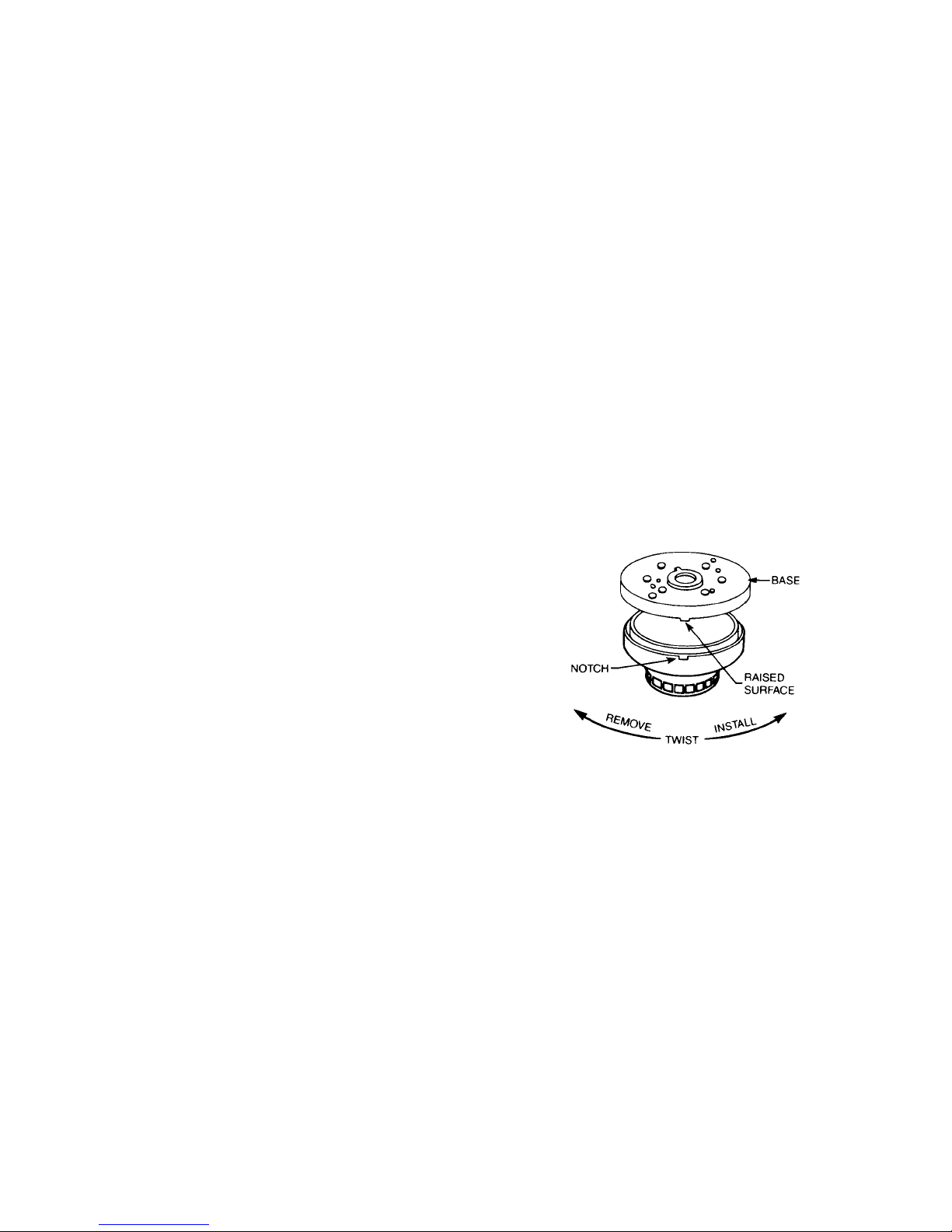
INSTALLATION OF DETECTOR HEAD
1. Align notch in detector cover to raised surface on
outer ring of base; refer to Figure 2.
TEMPERATURE HUMIDITY PRESSURE
AIR VELOCITY
The temperature range for the ILP-1/ILPT-1 detector
is from 32°F (0°C) to 100°F (38°C). Use the detector
in environments where the humidity does not exceed
93% (non-condensating). Normal changes of
atmospheric pressure do not affect detector sensitivity.
The air velocity range is 0-4000 ft/min for open areas
applications.
ILP-1 Air Duct Applications
In Air Duct applications, the Model ILP-1 requires Air
Duct Cover P/N 305-093076. Do not use the Model
ILP-1 with any other air duct covers. The air duct cover
part numbers are located on the air duct cover flange
near the sensitivity test jack trap door.
Figure 2
Mounting The Base
2. Push detector head into base and rotate clockwise
to make electrical connections. The detector
automatically stops and locks into place.
3. To remove, push detector head up into the base
while rotating the detector head counterclockwise.
Continue to rotate counterclockwise until stop is
reached; then pull downward to disengage
from base.
2
 Loading...