


EN Dear Customer,
Gigaset Communications GmbH is the legal successor to
Siemens Home and Office Communication Devices GmbH &
Co. KG (SHC), which in turn continued the Gigaset business
of Siemens AG. Any statements made by Siemens AG or
SHC that are found in the user guides should therefore be
understood as statements of Gigaset Communications
.
GmbH
We hope you enjoy your Gigaset.
DE Sehr geehrte Kundin, sehr geehrter Kunde,
FR Chère Cliente, Cher Client,
IT Gentile cliente,
NL Geachte klant,
ES Estimado cliente,
PT SCaros clientes,
die Gigaset Communications GmbH ist Rechtsnachfolgerin
der Siemens Home and Office Communication Devices
GmbH & Co. KG (SHC), die ihrerseits das Gigaset-Geschäft
der Siemens AG fortführte. Etwaige Erklärungen der
Siemens AG oder der SHC in den Bedienungsanleitungen
sind daher als Erklärungen der Gigaset Communications
GmbH zu verstehen.
Wir wünschen Ihnen viel Freude mit Ihrem Gigaset.
la société Gigaset Communications GmbH succède en droit
à Siemens Home and Office Communication Devices GmbH
& Co. KG (SHC) qui poursuivait elle-même les activités Gigaset de Siemens AG. Donc les éventuelles explications de Siemens AG ou de SHC figurant dans les modes d’emploi
doivent être comprises comme des explications de Gigaset
Communications GmbH.
Nous vous souhaitons beaucoup d’agrément avec votre
Gigaset.
la Gigaset Communications GmbH è successore della Siemens Home and Office Communication Devices GmbH &
Co. KG (SHC) che a sua volta ha proseguito l’attività della
Siemens AG. Eventuali dichiarazioni della Siemens AG o
della SHC nei manuali d’istruzione, vanno pertanto intese
come dichiarazioni della Gigaset Communications GmbH.
Le auguriamo tanta soddisfazione con il vostro Gigaset.
Gigaset Communications GmbH is de rechtsopvolger van
Siemens Home and Office Communication Devices GmbH &
Co. KG (SHC), de onderneming die de Gigaset-activiteiten
van Siemens AG heeft overgenomen. Eventuele uitspraken
of mededelingen van Siemens AG of SHC in de gebruiksaanwijzingen dienen daarom als mededelingen van Gigaset
Communications GmbH te worden gezien.
Wij wensen u veel plezier met uw Gigaset
la Gigaset Communications GmbH es derechohabiente de la
Siemens Home and Office Communication Devices GmbH &
Co. KG (SHC) que por su parte continuó el negocio Gigaset
de la Siemens AG. Las posibles declaraciones de la
Siemens AG o de la SHC en las instrucciones de uso se
deben entender por lo tanto como declaraciones de la Gigaset Communications GmbH.
Le deseamos que disfrute con su Gigaset.
Gigaset Communications GmbH é a sucessora legal da Siemens Home and Office Communication Devices GmbH &
Co. KG (SHC), que, por sua vez, deu continuidade ao sector
de negócios Gigaset, da Siemens AG. Quaisquer declarações por parte da Siemens AG ou da SHC encontradas nos
manuais de utilização deverão, portanto, ser consideradas
como declarações da Gigaset Communications GmbH.
Desejamos que tenham bons momentos com o seu Gigaset.
DA Kære Kunde,
FI Arvoisa asiakkaamme,
SV Kära kund,
NO Kjære kunde,
EL Αγ α πητή πελάτισσα, αγαπητέ πελάτη,
HR Poštovani korisnici,
.
SL Spoštovani kupec!
Gigaset Communications GmbH er retlig efterfølger til Siemens Home and Office Communication Devices GmbH &
Co. KG (SHC), som fra deres side videreførte Siemens AGs
Gigaset-forretninger. Siemens AGs eller SHCs eventuelle
forklaringer i betjeningsvejledningerne skal derfor forstås
som Gigaset Communications GmbHs forklaringer.
Vi håber, du får meget glæde af din Gigaset.
Gigaset Communications GmbH on Siemens Home and
Office Communication Devices GmbH & Co. KG (SHC)-yri-
tyksen oikeudenomistaja, joka jatkoi puolestaan Siemens
AG:n Gigaset-liiketoimintaa. Käyttöoppaissa mahdollisesti
esiintyvät Siemens AG:n tai SHC:n selosteet on tämän
vuoksi ymmärrettävä Gigaset Communications GmbH:n
selosteina.
Toivotamme Teille paljon iloa Gigaset-laitteestanne.
Gigaset Communications GmbH övertar rättigheterna från
Siemens Home and Office Communication Devices GmbH &
Co. KG (SHC), som bedrev Gigaset-verksamheten efter Siemens AG. Alla förklaringar från Siemens AG eller SHC i
användarhandboken gäller därför som förklaringar från
Gigaset Communications GmbH.
Vi önskar dig mycket nöje med din Gigaset.
Gigaset Communications GmbH er rettslig etterfølger etter
Siemens Home and Office Communication Devices GmbH &
Co. KG (SHC), som i sin tur videreførte Gigaset-geskjeften i
Siemens AG. Eventuelle meddelelser fra Siemens AG eller
SHC i bruksanvisningene er derfor å forstå som meddelelser
fra Gigaset Communications GmbH.
Vi håper du får stor glede av din Gigaset-enhet.
η Gigaset Communications GmbH είναι η νομική διάδοχος της
Siemens Home and Office Communication Devices GmbH &
Co. KG (SHC), η οποία έχει αναλάβει την εμπορική
δραστηριότητα Gigaset της Siemens AG. Οι δηλώσεις της
Siemens AG ή της SHC στις
επομένως δηλώσεις της Gigaset Communications GmbH.
Σας ευχόμαστε καλή διασκέδαση με τη συσκευή σας Gigaset.
Gigaset Communications GmbH pravni je sljednik tvrtke
Siemens Home and Office Communication Devices GmbH &
Co. KG (SHC), koji je nastavio Gigaset poslovanje tvrtke
Siemens AG. Zato sve izjave tvrtke Siemens AG ili SHC koje
se nalaze u uputama za upotrebu treba tumačiti kao izjave
tvrtke Gigaset Communications GmbH.
Nadamo se da sa zadovoljstvom koristite svoj Gigaset
uređaj.
Podjetje Gigaset Communications GmbH je pravni naslednik
podjetja Siemens Home and Office Communication Devices
GmbH & Co. KG (SHC), ki nadaljuje dejavnost znamke
Gigaset podjetja Siemens AG. Vse izjave podjetja Siemens
AG ali SHC v priročnikih za uporabnike torej veljajo kot izjave
podjetja Gigaset Communications GmbH.
Želimo vam veliko užitkov ob uporabi naprave Gigaset.
οδηγίες χρήσ
ης αποτ
ελούν
Issued by
Gigaset Communications GmbH
Schlavenhorst 66, D-46395 Bocholt
Gigaset Communications GmbH is a trademark
licensee of Siemens AG
© Gigaset Communications GmbH 2008
All rights reserved.
Subject to availability. Rights of modifications
reserved.
www.gigaset.com

CS Vážení zákazníci,
společnost Gigaset Communications GmbH je právním
nástupcem společnosti Siemens Home and Office
Communication Devices GmbH & Co. KG (SHC), která dále
přejala segment produktů Gigaset společnosti Siemens AG.
Jakékoli prohlášení společnosti Siemens AG nebo SHC, které
naleznete v uživatelských příručkách, je třeba považovat za
prohlášení společnosti Gigaset Communications GmbH.
Doufáme, že jste s produkty Gigaset spokojeni.
SK Vážený zákazník,
Spoločnosť Gigaset Communications GmbH je právnym
nástupcom spoločnosti Siemens Home and Office
Communication Devices GmbH & Co. KG (SHC), ktorá zasa
pokračovala v činnosti divízie Gigaset spoločnosti Siemens
AG. Z tohto dôvodu je potrebné všetky vyhlásenia
spoločnosti Siemens AG alebo SHC, ktoré sa nachádzajú v
používateľských príručkách, chápať ako vyhlásenia
spoločnosti Gigaset Communications GmbH.
Veríme, že budete so zariadením Gigaset spokojní.
PL Szanowny Kliencie,
Firma Gigaset Communications GmbH jest spadkobiercą
prawnym firmy Siemens Home and Office Communication
Devices GmbH & Co. KG (SHC), która z kolei przejęła
segment produktów Gigaset od firmy Siemens AG. Wszelkie
oświadczenia firm Siemens AG i SHC, które można znaleźć
w instrukcjach obsługi, należy traktować jako oświadczenia
firmy Gigaset Communications GmbH.
Życzymy wiele przyjemności z korzystania z produktów
Gigaset.
TR Sayın Müşterimiz,
Gigaset Communications GmbH, Siemens AG'nin Gigaset
işletmesini yürüten Siemens Home and Office
Communication Devices GmbH & Co. KG (SHC)'nin yasal
halefidir. Kullanma kılavuzlarında bulunan ve Siemens AG
veya SHC tarafından yapılan bildiriler Gigaset
Communications GmbH tarafından yapılmış bildiriler olarak
algılanmalıdır.
Gigaset'ten memnun kalmanızı ümit ediyoruz.
RO Stimate client,
Gigaset Communications GmbH este succesorul legal al
companiei Siemens Home and Office Communication
Devices GmbH & Co. KG (SHC), care, la rândul său, a
continuat activitatea companiei Gigaset a Siemens AG.
Orice afirmaţii efectuate de Siemens AG sau SHC şi incluse
în ghidurile de utilizare vor fi, prin urmare, considerate a
aparţine Gigaset Communications GmbH.
Sperăm ca produsele Gigaset să fie la înălţimea dorinţelor
dvs.
SR Poštovani potrošaču,
Gigaset Communications GmbH je pravni naslednik
kompanije Siemens Home and Office Communication
Devices GmbH & Co. KG (SHC), kroz koju je nastavljeno
poslovanje kompanije Gigaset kao dela Siemens AG. Stoga
sve izjave od strane Siemens AG ili SHC koje se mogu naći u
korisničkim uputstvima treba tuma
Gigaset Communications GmbH.
Nadamo se da ćete uživati u korišćenju svog Gigaset
uređaja.
BG Уважаеми потребители,
Gigaset Communications GmbH е правоприемникът на
Siemens Home and Office Communication Devices GmbH
& Co. KG (SHC), която на свой ред продължи бизнеса на
подразделението Siemens AG. По тази причина
всякакви изложения, направени от Siemens AG или
SHC, които се намират в ръководствата за
потребителя, следва да се разбират като изложения на
Gigaset Communications GmbH.
Надяваме се да ползвате с удоволствие вашия Gigaset.
izjave kompanije
čiti kao
RU Уважаемыи покупатель!
Компания Gigaset Communications GmbH является
правопреемником компании Siemens Home and Office
Communication Devices GmbH & Co. KG (SHC), которая,
ою очередь, приняла подразделение Gigaset в свое
в св
управление от компании Siemens AG. Поэтому любые
заявления, сделанные от имени компании Siemens AG
или SHC и встречающиеся в руководствах
пользователя, должны восприниматься как заявления
компании Gigaset Communications GmbH.
Мы надеемся, что продукты Gigaset удовлетворяют
вашим требованиям.
HU T
isztelt Vásárló!
A Siemens Home and Communication Devices GmbH & Co.
KG (SHC) törvényes jogutódja a Gigaset Communications
GmbH, amely a Siemens AG Gigaset üzletágának utódja.
Ebből következően a Siemens AG vagy az SHC felhasználói
kézikönyveiben található bármely kijelentést a Gigaset
Communications GmbH kijelentésének kell tekinteni.
Reméljük, megelégedéssel használja Gigaset készülékét.
Issued by
Gigaset Communications GmbH
Schlavenhorst 66, D-46395 Bocholt
Gigaset Communications GmbH is a trademark
licensee of Siemens AG
© Gigaset Communications GmbH 2008
All rights reserved.
Subject to availability. Rights of modifications
reserved.
www.gigaset.com

Issued by
Siemens Home and Office Communication Devices GmbH & Co. KG
Schlavenhorst 66
D-46395 Bocholt
© Siemens Home and Office Communication Devices GmbH & Co. KG 2007
All rights reserved. Subject to availability.
Rights of modification reserved.
Gigaset
www.siemens.com/gigaset
CE460 IP R
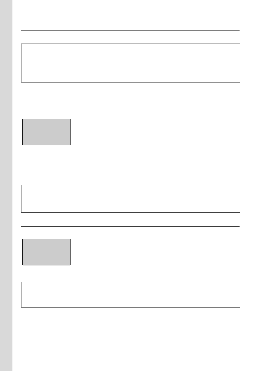
The handset at a glance
The handset at a glance
1
14
¨ V
2
11.01.07 11:56
§§§§§§INT§§§§§ §§§§Menu§
12
13
11
9
3
4
6
5
10
7
8
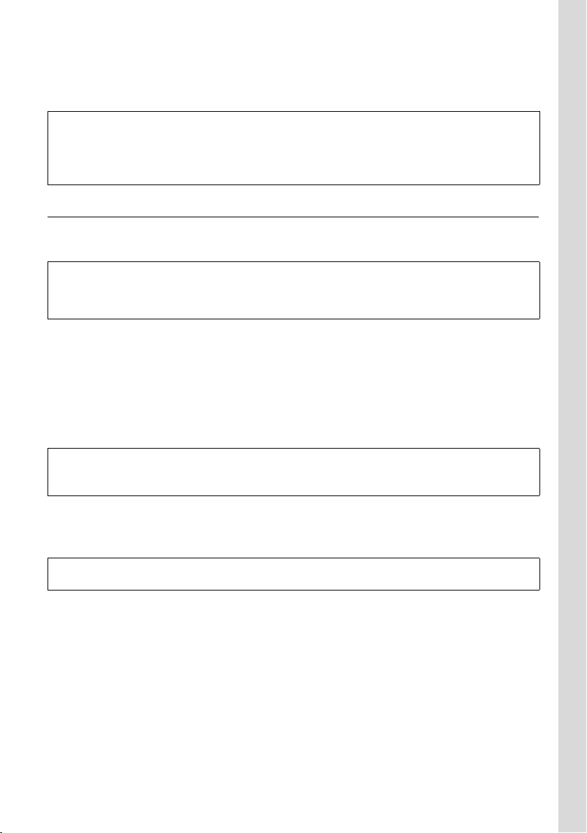
The base station at a glance
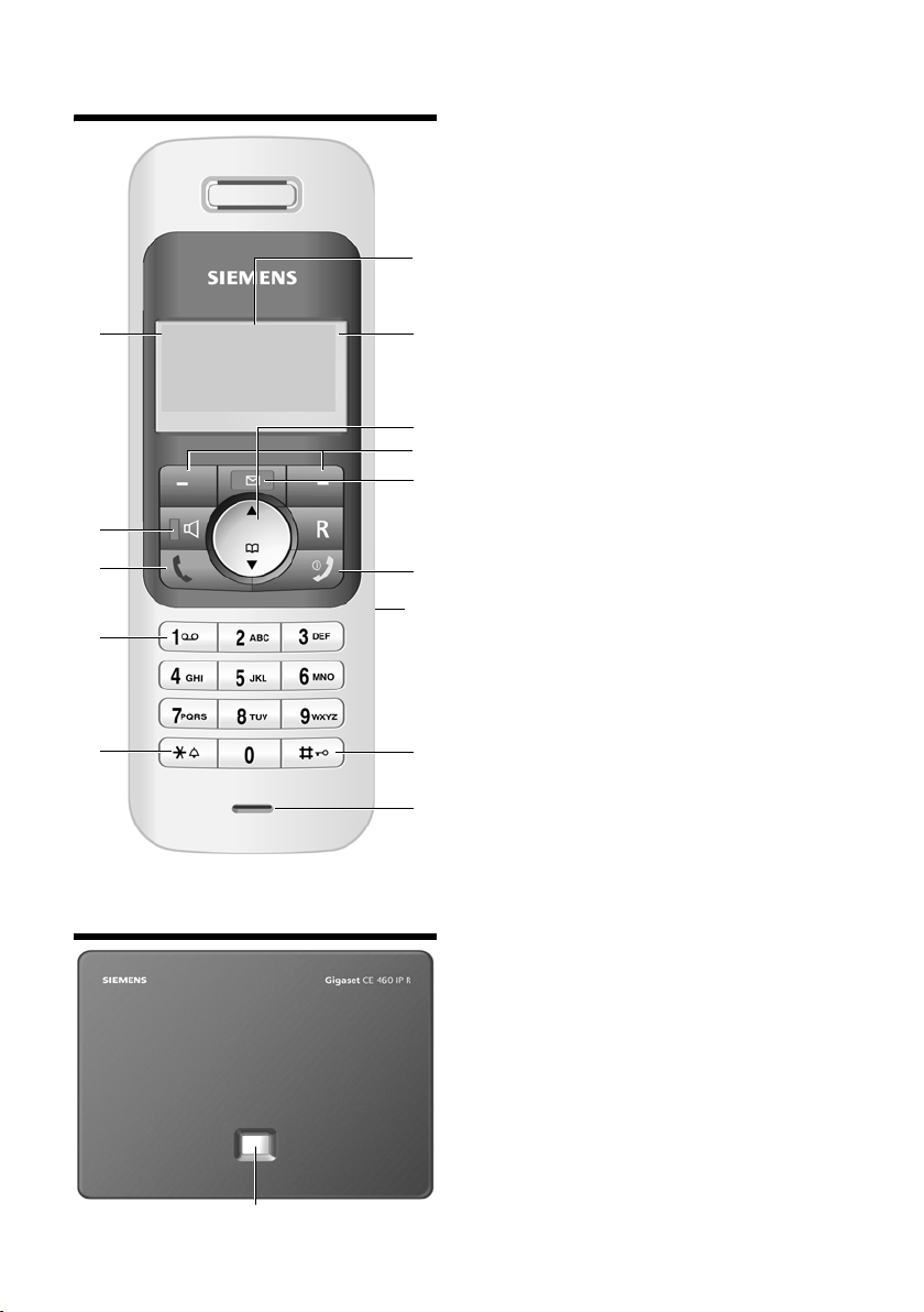
Handset keys
1 Display in idle status (example)
2 Battery charge status
e V U (1/3 charged to fully
charged)
= flashes: battery almost flat
e V U flashes: battery charging
3 Control key (page 31)
4 Display keys (page 32)
5 End call key, On/Off key
End call, cancel function, go back one menu
level (press briefly), back to idle status (press
and hold), activate/deactivate handset
(press and hold in idle status)
6 Message key
Access calls list
Flashes: new call
7 Hash key
Keypad lock on/off (press and hold,
page 31)
Toggle between upper/lower case letters
and digits for text entry (page 124)
8 Microphone
9 Star key
Ringer tones on/off (press and hold in idle
status)
10 Connection socket for headset (page 22)
11 Key 1 (press and hold)
Fast access to network mailbox (page 47)
12 Handsfree key
Switch between earpiece and handsfree
mode, open last number redial list (press in
idle status)
Lights up: handsfree talking activated
Flashes: incoming call
13 Tal k ke y
Accept a call, open last number redial list
(press in idle status)
14 Signal strength
¦ § ¨ (low to high)
¥ flashes: no reception
Base station key
1 Paging key
Lights up: base station is connected with the
mains power supply
Flashes: data transfer to LAN/WAN connection
Press briefly: start paging (page 50)
Press and hold:
set base station to registration mode to register the handset (page 48)
1
1

Contents
Contents
The handset at a glance . . . . . . . . 1
The base station at a glance . . . . 1
Safety precautions . . . . . . . . . . . . 4
Gigaset CE 460 IP R – more than
just a telephone . . . . . . . . . . . . . . 5
VoIP – making calls via
the Internet . . . . . . . . . . . . . . . . . . 6
Base station components . . . . . . . 6
First steps . . . . . . . . . . . . . . . . . . . . 8
Pack contents . . . . . . . . . . . . . . . . . . . . 8
Setting up the handset for use . . . . . . . 8
Installing the base station . . . . . . . . . 11
Connecting the base station . . . . . . . 12
Configuring the Internet connection on
the base station router . . . . . . . . . . . . 15
Making settings for VoIP telephony on
the base station phone . . . . . . . . . . . 17
Belt clip and headset . . . . . . . . . . . . . 22
Menu trees . . . . . . . . . . . . . . . . . . 23
Phone menu . . . . . . . . . . . . . . . . . . . . 23
Router Web configurator menu . . . . . 26
Phone Web configurator menu . . . . . 27
Making calls . . . . . . . . . . . . . . . . . 28
Making an external call . . . . . . . . . . . 28
Ending a call . . . . . . . . . . . . . . . . . . . . 28
Accepting a call . . . . . . . . . . . . . . . . . 29
Call display . . . . . . . . . . . . . . . . . . . . . 29
Handsfree talking . . . . . . . . . . . . . . . . 30
Muting the handset . . . . . . . . . . . . . . 30
Operating the handset . . . . . . . . 31
Activating/deactivating the handset . 31
Activating/deactivating the
keypad lock . . . . . . . . . . . . . . . . . . . . . 31
Control key . . . . . . . . . . . . . . . . . . . . 31
Display keys . . . . . . . . . . . . . . . . . . . . 32
Reverting to idle status . . . . . . . . . . . . 32
Menu guidance . . . . . . . . . . . . . . . . . 33
Correcting incorrect entries . . . . . . . . 33
VoIP telephony via Gigaset.net 34
Searching for subscribers in the
Gigaset.net directory . . . . . . . . . . . . . 34
Calling a Gigaset.net subscriber . . . . . 37
Network services - VoIP . . . . . . . 38
Settings for all calls . . . . . . . . . . . . . . . 38
Functions during a call . . . . . . . . . . . . 39
Using the directory and lists . . 40
Directory . . . . . . . . . . . . . . . . . . . . . . . 40
Last number redial list . . . . . . . . . . . . 43
Opening lists with the message key . . 44
Using the network mailbox . . . 47
Configuring the network mailbox for fast
access . . . . . . . . . . . . . . . . . . . . . . . . . 47
Network mailbox message . . . . . . . . . 47
Using several handsets . . . . . . . 48
Registering handsets . . . . . . . . . . . . . . 48
De-registering handsets . . . . . . . . . . . 49
Changing a handset's internal number 49
Changing the name of a handset . . . . 50
Locating a handset ("paging") . . . . . . 50
Making internal calls . . . . . . . . . . . . . . 50
Handset settings . . . . . . . . . . . . 52
Changing the display language . . . . . 52
Setting the display . . . . . . . . . . . . . . . 52
Activating/deactivating auto answer . 53
Adjusting the loudspeaker volume . . . 53
Changing ringer tones . . . . . . . . . . . . 53
Advisory tones . . . . . . . . . . . . . . . . . . 54
Using the handset as an alarm clock . 55
Restoring the handset to the factory
settings . . . . . . . . . . . . . . . . . . . . . . . . 56
Setting the base station . . . . . . 56
Changing the system PIN of the base
station phone . . . . . . . . . . . . . . . . . . . 56
Restoring the base station to the factory
settings . . . . . . . . . . . . . . . . . . . . . . . . 56
Activating/deactivating the on
hold music . . . . . . . . . . . . . . . . . . . . . . 57
Activating/deactivating
repeater mode . . . . . . . . . . . . . . . . . . 58
Updating the base station phone's
firmware . . . . . . . . . . . . . . . . . . . . . . . 58
2

Contents
Making VoIP settings . . . . . . . . . 59
Setting the base station phone's IP address
in LAN . . . . . . . . . . . . . . . . . . . . . . . . . 59
Entering/changing the first VoIP account
with the connection assistant . . . . . . 61
Entering/changing the first VoIP account
without the connection assistant . . . 61
Activating/deactivating display of VoIP
status codes . . . . . . . . . . . . . . . . . . . . 63
Checking the base station phone's MAC
address . . . . . . . . . . . . . . . . . . . . . . . . 63
Using the Web configurators . . . 64
Configuring the base station router and
phone via a PC . . . . . . . . . . . . . . . . . . 64
Starting the Web configurator . . . . . . 65
Logging off . . . . . . . . . . . . . . . . . . . . . 65
Structure of the Web pages . . . . . . . . 66
Opening Web pages . . . . . . . . . . . . . . 68
Router Web configurator . . . . . . 69
Connecting the PC to the router Web
configurator . . . . . . . . . . . . . . . . . . . . 69
Login . . . . . . . . . . . . . . . . . . . . . . . . . . 69
Internet – configuring the connection to
the Internet. . . . . . . . . . . . . . . . . . . . . 71
Connection – entering access data for the
Internet connection . . . . . . . . . . . . . . 71
Setting up the Firewall . . . . . . . . . . . . 74
Setting up NAT . . . . . . . . . . . . . . . . . . 75
DNS – entering the DNS server . . . . . 78
QoS – setting the Quality of Service,
prioritising VoIP . . . . . . . . . . . . . . . . . 78
Setting Routing . . . . . . . . . . . . . . . . . . 79
Configuring the local network . . . . . . 80
Defining the router's name
and domain . . . . . . . . . . . . . . . . . . . . 81
Setting the Regional Options . . . . . . . 81
Setting or changing a password . . . . . 82
Setting the time until
automatic log-off . . . . . . . . . . . . . . . . 82
Configuring Remote Management for the
router from external networks . . . . . . 82
Updating the router's firmware . . . . . 83
Displaying the security log . . . . . . . . . 83
Reboot . . . . . . . . . . . . . . . . . . . . . . . . 83
Checking status information
via the router . . . . . . . . . . . . . . . . . . . 84
Phone Web configurator . . . . . . 85
Connecting the PC to the phone Web
configurator . . . . . . . . . . . . . . . . . . . . 85
Logging in, setting the Web configurator
language . . . . . . . . . . . . . . . . . . . . . . . 86
IP Configuration . . . . . . . . . . . . . . . . . 87
Configuring telephone connections . . 89
Optimising voice quality for VoIP
connections . . . . . . . . . . . . . . . . . . . . 97
Assigning sending and receiving numbers
to handsets . . . . . . . . . . . . . . . . . . . . 100
Setting DTMF signalling for VoIP . . . 101
Defining local communication ports for
VoIP . . . . . . . . . . . . . . . . . . . . . . . . . . 102
Setting Area Code Predialling . . . . . . 103
Loading and deleting directories to/from
the PC. . . . . . . . . . . . . . . . . . . . . . . . . 103
Defining the server for firmware updates,
starting the update . . . . . . . . . . . . . . 106
Activating/deactivating the automatic
version check . . . . . . . . . . . . . . . . . . 107
Activating VoIP status message
display . . . . . . . . . . . . . . . . . . . . . . . . 107
Checking status information via your
phone . . . . . . . . . . . . . . . . . . . . . . . . 108
Messaging . . . . . . . . . . . . . . . . . . . . . 109
Appendix . . . . . . . . . . . . . . . . . 112
Symbols and typographical conventions
used . . . . . . . . . . . . . . . . . . . . . . . . . . 112
Care . . . . . . . . . . . . . . . . . . . . . . . . . . 112
Contact with liquid . . . . . . . . . . . . . . 112
Questions and answers . . . . . . . . . . . 113
Searching for service information . . 119
Service (Customer Care) . . . . . . . . . . 120
Authorisation . . . . . . . . . . . . . . . . . . 121
Specifications . . . . . . . . . . . . . . . . . . 121
Writing and editing a text message . 124
Gigaset CE 460 IP R – Free software . 127
Accessories . . . . . . . . . . . . . . . . 134
Glossary . . . . . . . . . . . . . . . . . . 135
Index . . . . . . . . . . . . . . . . . . . . . 147
3
Safety precautions
Warning:
Read the safety precautions and the user guide before use.
Explain their contents and the potential hazards associated with using the telephone to your children.
Only use the mains adapter supplied, as indicated on the underside of the base station.
$
Use only recommended rechargeable batteries (page 121) of the same type! Never use
a conventional (non-rechargeable) battery or other battery types as this could result in significant health risks and personal injury.
‹
Œ
ƒ
Insert rechargeable batteries with the correct polarity, and use them according to this user
guide (polarity symbols can be seen in the handset's battery compartment, page 8).
The operation of medical appliances may be affected. Be aware of the technical conditions
in your particular environment, e.g. doctor's surgery.
Do not hold the rear of the handset to your ear when it is ringing or when the handsfree
function is activated. Otherwise you risk serious and permanent damage to your hearing.
The handset may cause an unpleasant humming noise in hearing aids.
Do not install the base station in bathrooms or shower rooms. The handset and base station are not splashproof (page 112).
Do not use your phone in environments with a potential explosion hazard, e.g. paint
shops.
If you give your Gigaset to someone else, make sure you also give them the user guide.
All electrical and electronic equipment must be disposed of separately from general
household waste using the sites designated by local authorities.
If a product displays this symbol of a crossed-out rubbish bin, the product is subject to
European Directive 2002/96/EC.
The appropriate disposal and separate collection of used equipment serve to prevent
potential harm to the environment and to health. They are a precondition for the re-use
and recycling of used electrical and electronic equipment.
For further information on disposing of your used equipment, please contact your local
authority, your refuse collection service or the dealer you purchased the product from.
Please note:
When the keypad lock is active you cannot even call emergency numbers!
Not all of the functions described in this manual are available in all countries.
4

Gigaset CE 460 IP R – more than just a telephone
Gigaset CE 460 IP R – more than just a telephone
Your Gigaset CE 460 IP R is not only a router and phone in one device that you can use to
make cost-effective calls via the Internet (VoIP - Voice over IP) and with which you can connect other participants in your local network (e.g. PCs) to the Internet via the same Internet
account;
your Gigaset CE 460 IP R can do much more:
u Multiline: Register up to six handsets to your base station and set up an individual VoIP
account with its own phone number for each member of your family (up to six accounts
with different VoIP providers). Your phone can then be reached via up to six different
phone numbers, which you can assign to the individual handsets. If a member of your
family is called on their number, only their handset will ring.
u Use Gigaset.net for VoIP calls. Connect your base station to the mains power supply and
Internet and make calls – without making any further VoIP settings – to other
Gigaset.net subscribers free of charge (page 34).
u Use the base station router wizard. When you are putting your base station into service,
the wizard guides you step-by-step through the configuration of your Internet connection (page 15).
u Configure the VoIP connection directly on your handset. The connection assistant
downloads general data about a VoIP provider from the Internet and guides you through
entering your person al data (first accoun t). This makes it eas y for you to star t us ing VoIP
(page 18).
u Make further settings on your PC, if necessary. The phone has two Web interfaces
(router and phone Web configurator), which you can access via the Web browser on
your PC (page 85).
u Use your base station's firewall and NAT (Network Address Translation). This will allow
you to protect your local network from unauthorised access from the Internet.
u Assign individual passwords (a system PIN and router password) to protect your base
station's phones and routers against unauthorised access (page 56, page 82).
u Save up to 100 phone numbers on your handset (page 40).
u Transfer your Outlook contacts from the PC onto your handset. Or back up the handset
directory on your PC (page 103).
u You can programme the keys of your handset with important phone numbers. The
phone number is then dialled by simply pressing the respective key (page 41).
u Keep your hands free when making a call. Use the handsfree function on your handset
(page 30) or use the convenient headset to make calls (page 22, accessories: not
included in the scope of delivery).
u Keep your base station up to date. Find out about firmware updates on the Internet
and download these to your base station (page 58, page 106).
u Use your handset as an alarm clock (page 55).
Your Gigaset CE 460 IP R has a protected operating system that offers increased security against
viruses from the Internet.
Enjoy using your new telephone!
5

VoIP – making calls via the Internet
VoIP – making calls via the Internet
With VoIP (Voice over Internet Protocol), your calls are not made via a fixed connection as
in the telephone network, but rather they are transmitted via the Internet in the form of
data packets.
You can take advantage of all the benefits of VoIP with your Gigaset CE 460 IP R:
u You can make cost-effective calls at high voice quality with subscribers on the Internet,
the fixed network or the mobile phone network.
u VoIP providers will give you personal numbers, with which you can be reached from the
Internet, the fixed network and any mobile phone network.
To be able to use VoIP, you need the following:
u A broadband Internet connection (e.g. DSL) with flat rate (recommended) or volume-
based price.
u Internet access, i.e. a DSL modem, which you can use to connect your base station's
router to the Internet, and an Internet account.
u Access to the services of a VoIP provider. Open up to six accounts with different VoIP
providers.
Base station components
The Gigaset CE 460 IP R base station includes two independent components: the base
station router and base station phone, also frequently described as the router and phone
in the text that follows. These components must be configured and managed separately
from one another.
Base station router
u You can make router settings for the Internet connection and local network, and man-
age your router on your PC using the router Web configurator (see page 69).
u You can protect the router and its settings via an individual password. This password will
not allow access to the base station phone settings.
u The router is supplied with the following standard settings:
– Private IP address: 192.168.1.1
– IP address block: 192.168.1.2 to 192.168.1.253
– DHCP server enabled with IP address block: 192.168.1.100 to 192.168.1.150
– Password: 0000 (4x zero)
6

VoIP – making calls via the Internet
Base station phone
u You can make phone or VoIP telephony settings with the handset or on your PC via the
phone Web configurator (see page 85).
u The phone settings are protected with a system PIN.
u The phone is supplied with the following standard settings for connection to the router.
– DHCP client: enabled
– IP address: 192.168.1.150
– Standard gateway and DNS server: 192.168.1.1
– System PIN: 0000
An existing connection is set between the router and phone by default.
System requirements for the PC you want to use to configure your base station
u Ethernet socket
u Web browser, such as Microsoft Internet Explorer version 6.0 or higher, or Mozilla
Firefox version 1.0.4 or higher
7
First steps Pack contents
First steps
Pack contents
The pack contains:
u one Gigaset CE 460 IP R base station
u one Gigaset C46 handset
u one mains adapter for the base station
u one charging cradle incl. mains adapter
u one Ethernet cable Cat 5 with RJ45 modular jacks
u two batteries
u one battery cover
u one belt clip
u one quick guide
Firmware updates:
Whenever there are new or improved functions for your Gigaset CE 460 IP R, phone and/or router
firmware updates will be made available for you to download to your base station (page 58, page 83).
If this results in operational changes to your phone, a new version of the existing user guide will be
published on the Internet at www.siemens.com/gigaset
Setting up the handset for use
The display is protected by a plastic film. Please remove the protective film!
Inserting the batteries
Warning:
Only use the rechargeable batteries recommended by Siemens Home and Office Communication
Devices GmbH & Co. KG on page 121. Never use a conventional (non-rechargeable) battery or other
battery types as this could result in significant health risks and personal injury.For example, the batteries could explode. The phone could also malfunction or be damaged as a result of using batteries
that are not of the recommended type.
8
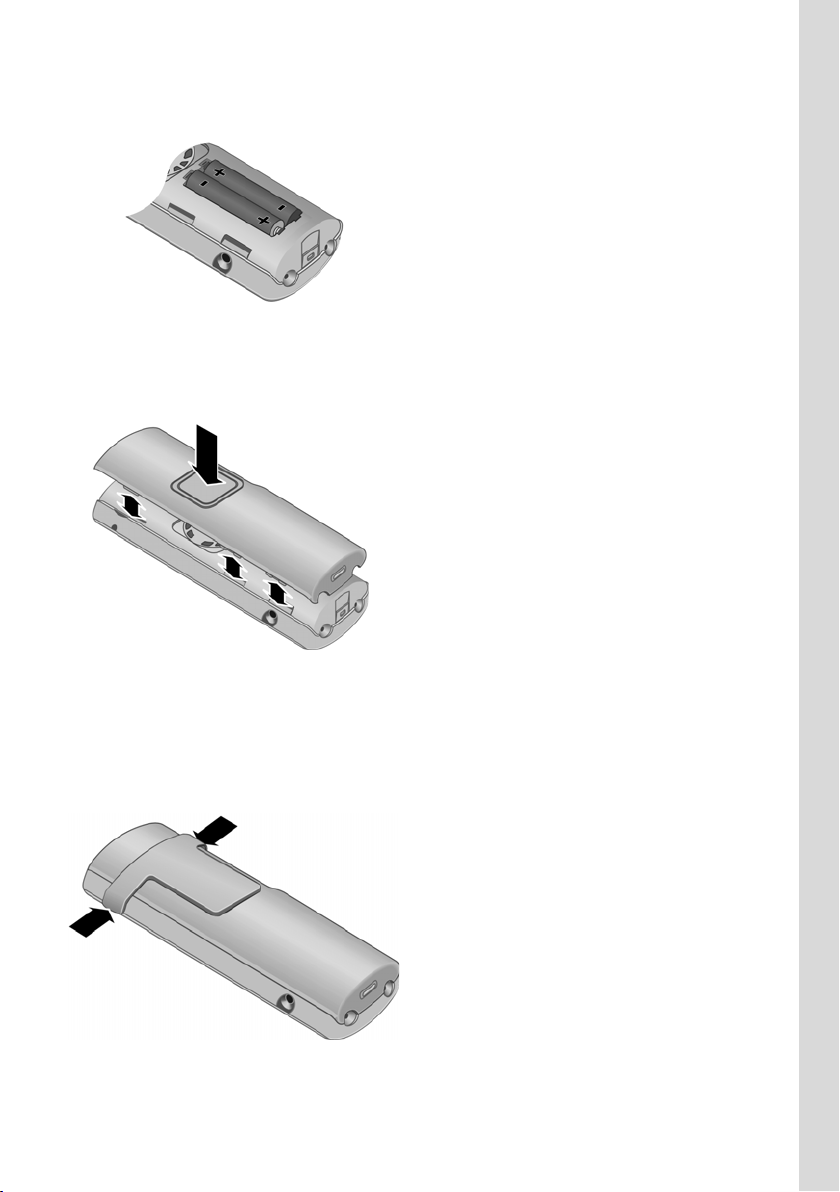
Setting up the handset for use First steps
¤ Insert the batteries the right way round (see figure).
The polarity is indicated in the battery compartment.
Closing the battery cover
¤ First align the notches on the side of the battery cover with the lugs on the inside of the
casing.
¤ Then press the cover so that it clicks into place.
Attaching the belt clip
There are notches for attaching the belt clip on the side of the handset at the same height
as the display.
¤ Press the belt clip onto the back of the handset so that the protrusions on the belt clip
engage with the notches.
9
First steps Setting up the handset for use
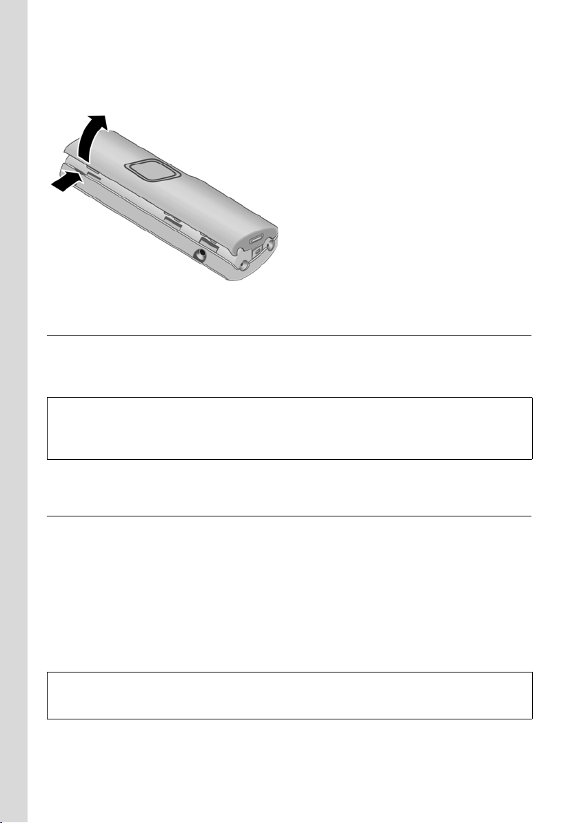
Opening the battery cover
¤ If fitted, remove belt clip.
¤ Insert a fingernail into the notch and pull the battery cover upwards.
Connecting the charging cradle
Connecting the charging cradle and mounting it on the wall (if required) is described at the
end of this user guide.
¤ To charge the batteries, leave the handset in the charging cradle.
Please note:
– Only place the handset in the charging cradle that is intended for it.
– If the handset has switched itself off because the batteries are flat and if it is then placed in the
charging cradle, it will switch itself on automatically.
For questions and problems see page 113.
Initial charging and discharging of batteries
Battery charging is indicated in the top right of the display by a flashing battery icon e,
V or U. During handset operation, the battery icon indicates the charge status of the
batteries (page 1).
The correct charge status can only be displayed when the batteries are first fully charged
and discharged through use.
¤ To do this, leave the handset in the charging cradle without interruption until the bat-
tery icon stops flashing in the display (around 13 hours).
¤ Once the batteries are fully charged, remove the handset from the charging cradle and
do not put it back again until the batteries are fully discharged.
Please note:
After the first battery charge and discharge, you may place your handset in the charging cradle after
every call.
Please note:
u Always repeat the charging and discharging procedure if you remove the batteries from
the handset and reinsert them.
10
Installing the base station First steps
u The batteries may warm up during charging. This is not dangerous.
u After a while the charge capacity of the batteries will decrease for technical reasons.
Please note:
You will find explanations for the symbols and typographical conventions used in this user guide in
the appendix, page 112.
Setting the date and time
§Menu§ ¢ Settings ¢ Date/Time
~ Enter the day, month and year in 6-digit format and press §OK§. Use q to move
between the fields.
~ Enter hours and minutes in 4-digit format (e.g. 0 7 1 5 for 07:15) and press
Use q to move between the fields.
The date and time are shown in the handset's idle display (page 1).
§OK§.
Registering the handset to the base station
The supplied handset is registered to the base station by default.
Instructions on how to register further handsets to the base station are given on page 48.
Installing the base station
The base station is designed for use in closed, dry rooms with a temperature range of
+5 °C to +45 °C.
¤ Place or hang the base station in a central position in your flat or house.
Please note:
u Never expose the telephone to heat sources, direct sunlight or other electrical
appliances.
u Protect your Gigaset from moisture, dust, corrosive liquids and vapours.
u The base station must only be operated on a LAN network (SELV network in accordance
with IEC 60950-1) inside a building.
11
First steps Connecting the base station
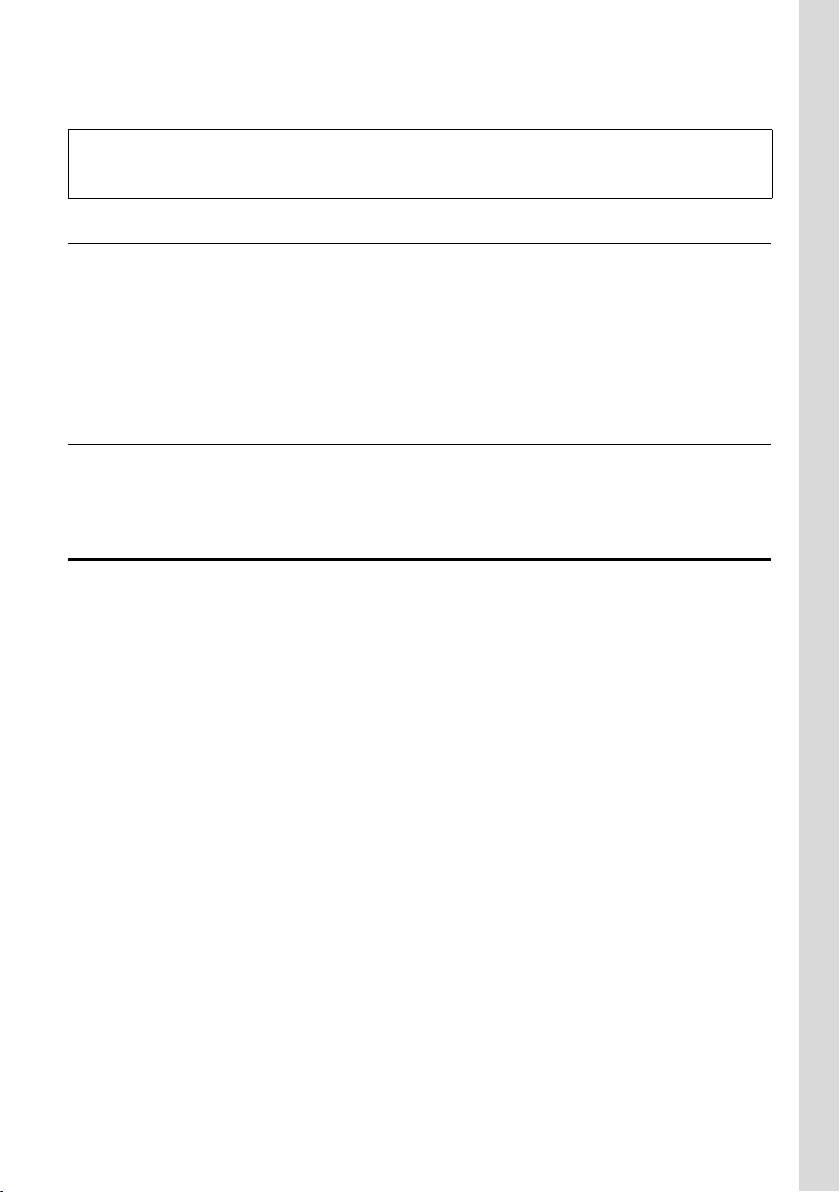
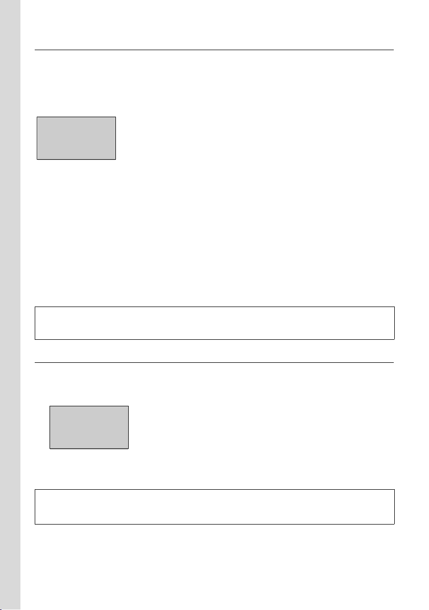
Connecting the base station
To be able to make calls via VoIP with your base station, you must connect the base station
with the Internet (WAN connection). You can connect additional devices to the base station
LAN connection; these devices can access the Internet via the base station router,
see Figure 1.
Internet
4
LAN
2
WAN
3
1
Figure 1 Base station connection
1 DSL modem for the Internet connection (WAN connection)
2 Gigaset CE 460 IP R base station
3 Gigaset C46 handset
4 Base station LAN connection, e.g.for the PC, hub, switch, router of a subnet
Follow the steps in the order given below:
1. Connect the base station WAN connection with the DSL modem
2. Connect the base station LAN connection with the Ethernet connection on your PC
3. Connect the base station with the mains power supply
Please note:
If there are devices connected to your modem (e.g. your PC), you must first shut these
down and switch them off. Then switch the modem off and disconnect it from the mains
power supply.
12
Connecting the base station First steps
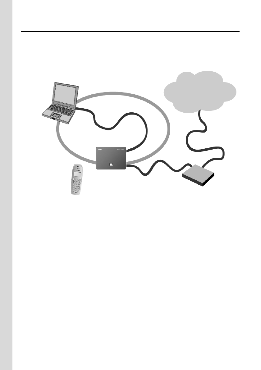
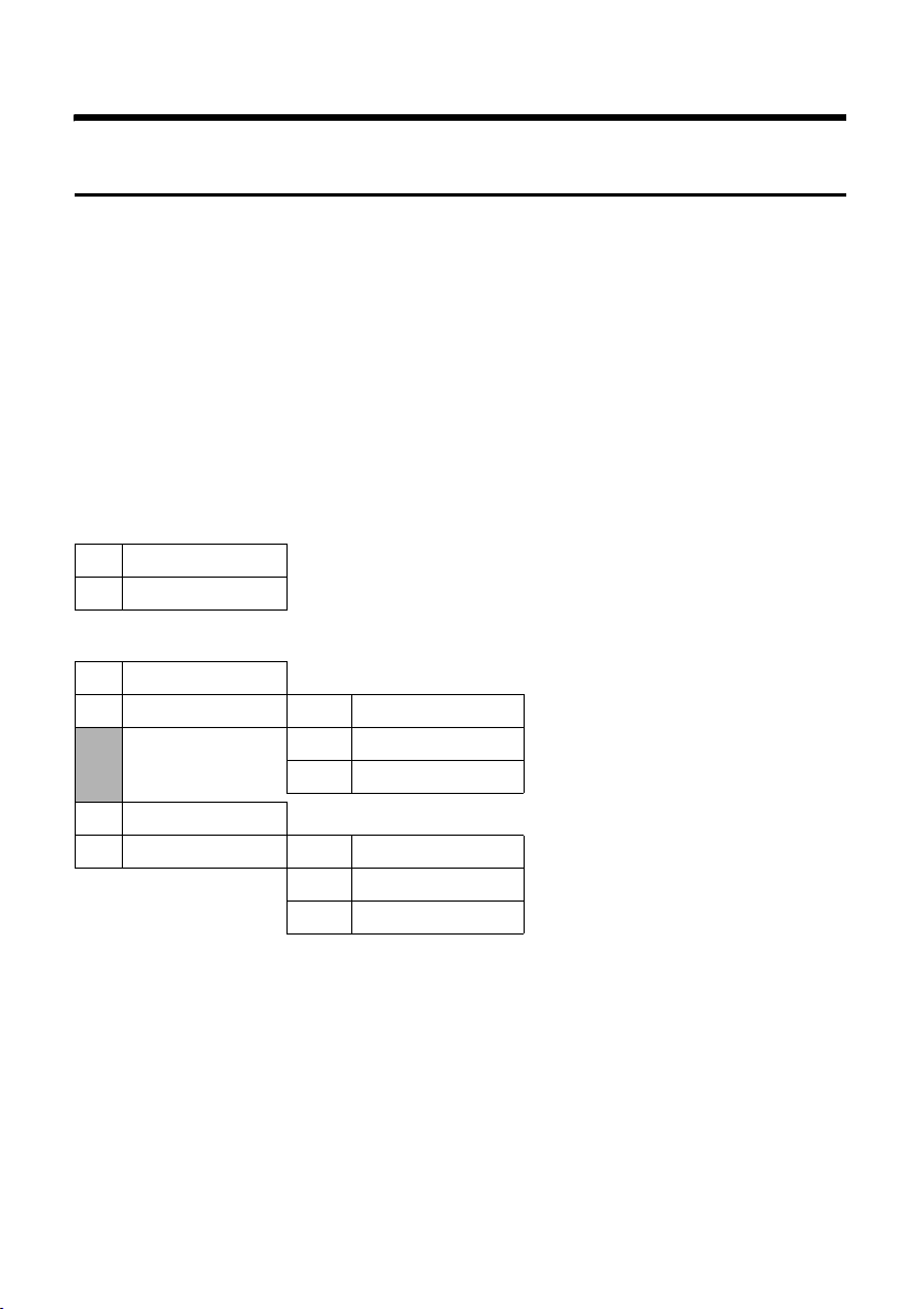
Connecting the base station with the modem
Connect the socket labelled WAN on your base station with your DSL modem. To do this,
use the Ethernet cable supplied.
3
1
3
2
1 Side view of the base station
2 Network plug (WAN) with network cable
3DSL modem
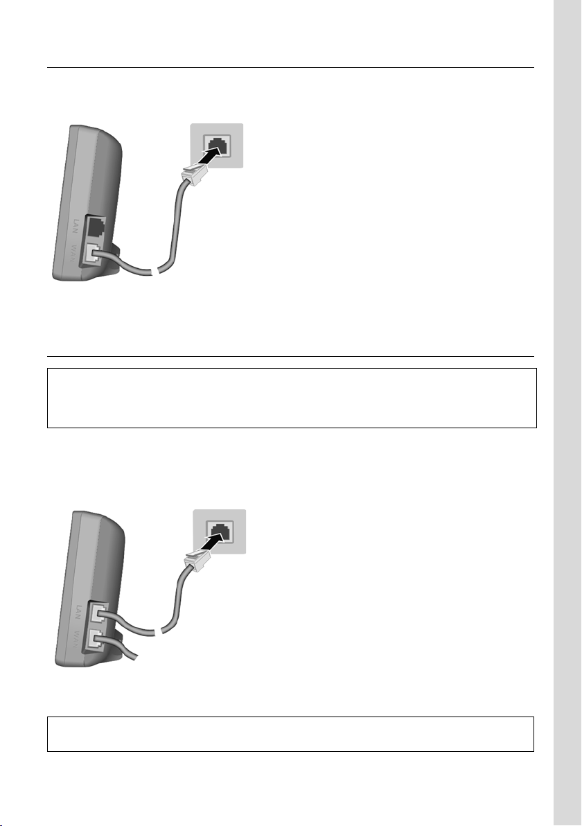
Connecting the PC with the base station
Before connecting a PC or laptop with the base station, please ensure:
– that a suitable network adapter is installed in/connected to your PC. Please read the operating
instructions that came with the adapter.
– that the DHCP client is enabled on your PC.
Connect the socket labelled LAN on your base station with the Ethernet connection of your
PC. To do this, use a category 5 (CAT5) Ethernet cable with RJ45 modular jacks on both
sides.
3
1
3
2
1 Side view of the base station
2 Network plug (LAN) with network cable
3 Ethernet connection on your PC
Please note:
To get started, you must connect your base station and PC directly via the Ethernet cable!
13
First steps Connecting the base station
Connecting the base station and modem with the mains power supply
Reconnect your modem to the mains power supply and turn it on.
Please note:
With some modems, you must wait a few minutes before turning it back on. Please consult your
modem description.
As soon as the LEDs on the modem light up, you can connect the base station with the
mains power supply.
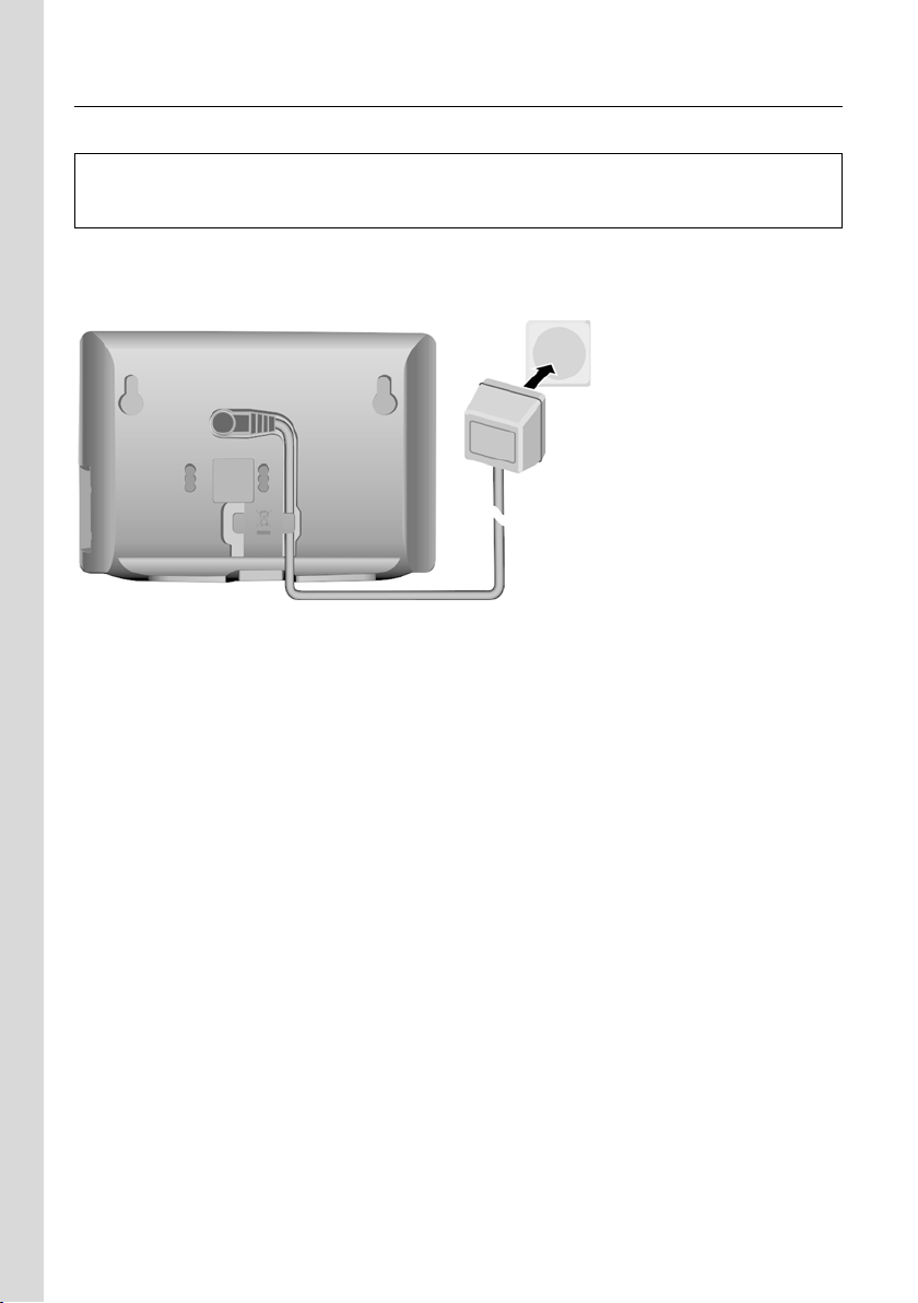
1
2
3
1 Underside of the base station
2 Insert the 230 V mains adapter into the socket on the base station.
3 Plug the mains adapter into a power socket.
The LED on the front of the base station lights up.
Please note:
u Keep the mains adapter plugged in at all times for operation, as the base station does
not work without a mains connection.
u Only use the mains adapter supplied with the base station.
14
Configuring the Internet connection on the base station router First steps
Configuring the Internet connection on the base station router
Make the basic Internet access settings for the base station router via your PC.
All data required for the configuration of the Internet connection can be obtained from
your Internet service provider.
Establishing the connection to the router Web configurator
¤ Switch on your PC.
¤ If necessary, enable DHCP on your PC, i.e. activate the Obtain IP address automatically
option in the network settings for the LAN connection.
¤ Start the Web browser (e.g. Internet Explorer or Firefox) on your PC.
¤ In the Web browser's address field, enter the name or private IP address (LAN address)
of the base station router:
http://router.gigaset or
http://192.168.1.1 (default setting)
The Welcome registration page of the router opens.
¤ Enter the router password (case sensitive) and click OK. 0000 is preset as the router
password by default.
Please note:
For security reasons you should change the router password at a later stage (page 82).
When registration is finished, the router's Home page opens.
Starting the wizard for the basic router settings
The wizard for the basic router settings helps you to put your base station into service and
guides you step-by-step through the configuration process with the most important settings.
¤ Click the Basic Setup Wizard entry to start the wizard.
The Regional Options Web page is displayed.
The wizard is operated as follows:
When you have made all the settings on a wizard Web page, click Next>. Click the <Back
button to return to the previous page. The Cancel button ends the wizard without changing the configuration of your base station.
15
First steps Configuring the Internet connection on the base station router
Selecting the time zone for the location of the router - selecting regional options
¤ From the Country list, select the country in which your base station is being operated.
By selecting the location, you ensure that your base station can function properly in that
location.
In Time Zone, the time zone that applies to the location is displayed. It indicates the difference between the local standard time (not summer time) and the co-ordinated world
time UTC (Co-ordinated Universal Time; previously GMT = Greenwich Mean Time).
Information about the time zone is important for various time-dependent operations on
the Internet. Access control to particular services can also be defined using time-based
rules.
¤ Click the Next> button.
The Internet Connection Web page is displayed.
Setting up an Internet connection
Set up your base station's Internet connection. To do this, enter the information received
from your Internet service provider (ISP) in the fields of the Web page.
¤ First select the WAN connection type from the Connection list.
The connection type depends on what kind of Internet connection you have and on the
agreements with your Internet service provider. The access data received from your Internet service provider for registration shows you which connection type you must select.
The options are PPPoE, Static IP Address, Dynamic IP Address and PPTP.
After you have made your selection, further fields will be displayed according to your con-
nection type; here you must enter the most important data required for an Internet connection. Further information about the individual connection types and the access data
required in each case can be found in the section "Connection – entering access data for
the Internet connection" on page 71.
For the Internet connection via PPPoE, your router is set so that it is permanently connected with the
Internet. This means that you can always be reached for VoIP calls.
Defining the maximum bandwidth for data uploads
The Upstream Rate field is displayed on the Internet Connection Web page, irrespective of the
Connection chosen. These parameters affect the voice quality of your VoIP calls.
In the Upstream Rate field, enter the maximum amount of your Internet connection's bandwidth that should be available for data uploads. First enter the upload stream rate given by
your Internet service provider. Then carry out tests to check that voice quality is good during calls made at the same time as data is being uploaded and adjust the rate accordingly.
You can find detailed information about this in the full user guide (Quality of Service –
QoS). This is available on the Internet at: www.siemens.com/gigaset.
More entries and settings for the Internet connection can be made at a later stage via the
Router Settings menu of the router Web configurator (page 71).
16
Making settings for VoIP telephony on the base station phone First steps
Completing the router configuration
¤ After entering your access data, click Next>.
The Apply Settings Web page is displayed.
¤ Click Finish. The start screen will be displayed again.
The Internet Status is displayed on the right-hand side of the start screen. If your settings
were successful, the status is Connected. Please note that it can take some time for the
router to establish the Internet connection.
¤ Click Log Off (top right-hand side of the Web page) to log off from the router Web
configurator.
You are now able to establish VoIP connections within Gigaset.net (page 34).
Test the Internet connection by surfing, i.e. entering a public URL in the Web browser address field
(http://www....).
Making settings for VoIP telephony on the base station phone
Before you can use the Internet (VoIP) to phone any other subscribers on the Internet, the
fixed network or the mobile phone network, you need the services of a VoIP provider.
Precondition: You have registered (e.g. via your PC) with a VoIP provider and set up an
account. The provider must support the VoIP SIP standard.
The following phone settings are necessary in order for you to use VoIP. You will receive all
information from your VoIP provider:
u Your user name with the VoIP provider, if this is required by the VoIP provider
u Your registration name
u Your password with the VoIP provider
u General settings for your VoIP provider (server addresses etc.)
The connection assistant will help you with the settings.
Before making the settings below, test the VoIP connection of your base station with the echo service
from Gigaset.net:
¥ Dial 1234#9 on your handset and press the talk key c.
If the connection has been correctly established, you will hear your echo.
If problems with your phone connection arise after you have made the VoIP settings below, check
whether you have correctly entered your access data or contact your VoIP provider.
Please note:
Here is a description of how to make settings on your handset.
You can also make settings via your phone's Web configurator. You can start this, e.g. directly from
the start screen of the router Web configurator. To do this, click Telephony Settings. You will find the
description of the phone Web configurator from page 85 onwards.
17
First steps Making settings for VoIP telephony on the base station phone
Starting the connection assistant
Prerequisite: The base station is connected with the mains power supply and the Internet.
Please note:
For your base station, i.e. for the phone and router, dynamic assignment of the IP address is preset
(DHCP enabled).
If you have disabled DHCP on the router, you must first assign your phone a fixed IP address and save
the router's private IP address (192.168.1.1 by default) as the standard gateway and DNS server on
your phone, see page 59.
If the handset battery is sufficiently charged, the message key f on the handset will flash
(around 20 minutes after you have put the handset in the charging cradle).
¤ Press the message key f.
You will see the following display:
Start VoIP
Connection
Assistant?
§§§§No§§§§ §§§§§Yes§§§§
§Yes§ Press the display key to start the connection assistant.
~ Enter the system PIN of the base station (the default is 0000) and press §OK§.
If you press §No§, the procedure that follows is described under "Entering names in the
Gigaset.net directory" on page 20.
Please note:
The connection assistant will also start automatically if you try to establish a connection via the Internet, before you have made the necessary settings.
You can also call up the connection assistant at any time via the menu (page 61).
Downloading data from the first VoIP provider
You will see the following display:
Select
VoIP-Provider?
§§§§No§§§§ §§§§§Yes§§§§
§Yes§ Press the display key.
The phone establishes an Internet connection to the Siemens server, where various profiles with general access data are available for different VoIP providers. If the phone cannot establish the connection, Server not accessible! will be displayed. See page 21 for details on how you can test/establish the
Internet connection if necessary.
The message Select country appears in the display.
After changing the display:
q Select country and press
Select provider is displayed.
18
§OK§.
Making settings for VoIP telephony on the base station phone First steps
After changing the display:
q Select your VoIP provider and press §OK§.
The necessary data for your VoIP provider is downloaded and saved on the phone.
Please note:
If the data for your VoIP provider is not offered for download, you must make the necessary settings
with the Web configurator at a later stage (page 90).
Press the display key §Back§ twice. You can then conduct the following steps with the connection
assistant (see "Entering user data for your first VoIP account").
Entering user data for your first VoIP account
En ter the VoIP u ser dat a fo r the firs t VoIP ac cou nt. Thi s da ta ca n be obt aine d from yo ur VoIP
provider.
You can enter five additional VoIP accounts (VoIP phone numbers) via the Web configurator at a later
stage (page 90). Your phone can then be reached via up to six different phone numbers. You can
assign the phone numbers to the individual handsets that are registered with the base station as
sending and receiving numbers (page 100).
Username:
Is only displayed when your provider requires a user name.
Enter name and press
Authentication Name:
Enter name and press
Authentication Password:
Enter password and press
§OK§.
§OK§.
§OK§.
Please note:
When making these entries, please remember the VoIP user data is case sensitive. If necessary, press
and hold the
If you have made all the necessary entries, the Gigaset.net assistant is started. You have
the option of entering yourself in the Gigaset.net online directory with your own choice
of name.
This step is only carried out when the device is first put into service (when the connection assistant
is started up for the first time). You can create the entry via the Gigaset.net directory (page 34).
# key to switch between upper and lower case and digits.
19
First steps Making settings for VoIP telephony on the base station phone
Entering names in the Gigaset.net directory
With Gigaset.net you can call other Gigaset.net users directly over the Internet free of
charge, without setting up an account with a VoIP provider and without making any further
settings. You can find Gigaset.net subscribers by carrying out a name search in the
Gigaset.net (page 34) directory.
The following appears in the handset's display:
Start
Gigaset.net
assistant?
§§§§No§§§§ §§§§§Yes§§§§
§Yes§ Press the display key if you want to enter yourself in the Gigaset.net directory.
If you press
settings".
Own Gigaset.net name:
Enter the name that you would like to be listed under in the Gigaset directory
and press
A connection to the Gigaset.net server is established.
If there is already an entry under this name, you receive a message to this effect and you
will be asked to enter a name again.
If an entry in the Gigaset.net directory is successful, the message "Name added to
Gigaset.net!" is displayed briefly.
If the attempt to create the entry fails (e.g. because the phone is not connected to the Internet), a
message to this effect is displayed briefly, see page 21. You can then create the entry later via the
Gigaset.net directory (page 34).
§No§, the procedure that follows is described under "Completing the
§OK§. The name may contain up to 25 characters.
Completing the settings
The handset returns to idle status.
If all the settings for your first VoIP account are correct and if the phone can establish a con-
nection to the VoIP server, then the internal name of the handset will be displayed:
L
¨ V
INT 1
11.02.07 11:56
§§§§INT§§§§ §§§§§Menu§§§§
You can now make calls with your phone via the Internet!
Please note:
To ensure that you can always be reached via the Internet, your base station router has been set so
that it is continuously connected to the Internet.
20

Making settings for VoIP telephony on the base station phone First steps
No connection to the Internet/VoIP server
If one of the following messages is displayed instead of the internal name after the connection assistant is closed, then either a fault has occurred or your information was incomplete:
Server not accessible!
The phone has no connection to the Internet.
¤ Check the cable connection between the base station and the modem/Internet connec-
tion.
¤ Check your router's Internet status:
¤ Start the router Web configurator (page 69).
The Internet Status is displayed on the start screen. If necessary, check the access data
stored in the router (page 71).
¤ Check whether the IP address settings for the base station phone and base station router
are compatible.
Please note the following:
– The IP address for the phone must belong to the address block for the router. For
example:the first three parts of the IP addresses for the phone and the router in subnet mask 255.255.255.0 must be identical.
– The IP address for the phone must not be assigned to any other LAN subscriber. If the
DHCP server for the router is enabled, then no static IP address can belong to the
address block that is reserved for dynamically assigning IP addresses (default setting:
192.168.1.100 – 192.168.1.150)
– If the phone is to be dynamically assigned an IP address, then the router's DHCP
server has to be activated.
¤ Find the phone's IP address via the handset menu:
§Menu§ ¢ Settings ¢ Base ¢ Local Network ¢ (enter system PIN) ¢ IP Address
¤ Start the phone Web configurator with the IP address (page 65).
If no connection can be established:
¤ change the settings on the router (activate DHCP server, change DHCP settings, see
page 80) or
¤ activate dynamic assignment of address to the phone (page 60) or
¤ change the phone's (fixed) IP address (page 60).
Recommendation:
You should restart your base station and the connected devices (PC) as soon as you make changes in
your LAN to IP addresses or address blocks. During the restart you should start the base station first
(page 83) and then the connected devices (PC). This will deactivate old IP addresses and force new
dynamic IP addresses to be assigned/requested.
21

First steps Belt clip and headset
SIP registration failed!
u Your personal data for registering with the VoIP provider may have been entered incom-
pletely or incorrectly.
¤ Check your entries for Username, Authentication Name and Authentication Password. In
particular, check your use of upper and lower case.
To do this, open the following menu on your handset:
§Menu§ ¢ Settings ¢ Base ¢ Telephony ¢ Vo IP
u The server address for the VoIP server has not yet been entered, or has been entered
incorrectly.
¤ Start the phone Web configurator.
¤ Open the following Web page: Settings ¢ Telephony ¢ Connections.
¤ Edit the server address where necessary.
Please note:
– STUN (Simple Transversal of UDP over NAT) should always be deactivated on your base station
phone (default setting), and a port number from the block 5056 – 5071 should be set for the local
SIP port (default 5060).
Check these settings if you cannot hear the other caller or if you cannot be reached.
You can set STUN mode (page 94) and the local SIP port (page 102) via the phone Web
configurator.
– If por t forwarding is activated on your router for the ports that have been registered as the SIP port
(default 5060) and the RTP port (default 5004), it makes sense to assign the phone a static IP
address (otherwise you may not be able to hear the other party during VoIP calls), see page 59.
Please note that the IP address and subnet mask depend on the router's address block.
You must also enter the standard gateway and DNS server. The IP address for the router is
generally entered here.
You will find other messages and possible measures in the "Questions and answers" section
on page 113.
Belt clip and headset
By using a belt clip and headset (optional) you can easily make your handset a constant
companion.
Attaching the belt clip
There are notches for attaching the belt clip on the side of the handset at approximately
the same height as the display.
¤ Press the belt clip onto the back of the handset so that the protrusions on the belt clip
engage with the notches.
The tongue of the belt clip must face the battery compartment.
Connection socket for headset
You can use headsets with jack connectors. The following models have been tested and are
therefore recommended: HAMA Plantronics M40, MX100 and MX150.
The transmission quality of other models cannot be guaranteed.
22
Phone menu
Menu trees
Phone menu
There are two ways to select a function:
Using number combinations ("shortcut")
¤ To open the main menu, press §Menu§ with the handset in idle status.
¤ Enter the number combination that is in front of the function in the menu tree.
¤ Example: §Menu§ 422 for "Set handset language".
Scrolling through the menus
¤ To open the main menu, press §Menu§ with the handset in idle status.
¤ Scroll to the function with the control key s and press §OK§.
2 Alarm Clock page 55
2-1 Activation
2-2 Wake up time
3 Audio Settings
3-1 Ringer Volume page 54
3-2 Ringer Melody 3-2-1 External Calls page 54
3-2-2 Internal Calls
3-2-3 Alarm Clock
3-3 Advisory Tones page 55
3-4 Battery Low 3-4-1 Off page 55
3-4-2 On
3-4-3 During Call
23

Phone menu
4 Settings
4-1 Date/Time page 11
4-2 Handset 4-2-1 Display 4-2-1-1 Screensaver page 52
4-2-1-2 Colour Scheme
4-2-1-3 Contrast
4-2-1-4 Backlight
4-2-2 Language page 52
4-2-3 Auto Answer page 53
4-2-4 Register Handset page 48
4-2-5 Reset Handset page 56
4-3 Base 4-3-1 Calls List Type 4-3-1-1 Missed Calls page 45
4-3-1-2 All Calls
4-3-2 Music on hold page 57
4-3-3 System PIN page 56
4-3-4 Base Reset page 57
4-3-5 Additional Fea-
4-3-5-1 Repeater Mode page 58
tures
4-3-6 Local Network 4-3-6-1 dynamic
page 60
IP address
4-3-6-2 IP Address page 60
4-3-6-3 Subnet Mask page 60
4-3-6-4 DNS Server page 61
4-3-6-5 Default Gateway page 61
4-3-7 Telephony
submenu see page 25
4-3-8 Firmware Update page 58
5 Voice Mail
5-1 Set Key 1 5-1-1 Network Mailbox page 47
6 Select Services
6-1 VoIP 6-1-6 For All Calls 6-1-6-1 Call Divert page 38
6-1-6-3 Call Waiting page 38
24

Phone menu
Submenu "Settings ¢ Base ¢ Telephony" 4-3-7
4-3-7 Telephony 4-3-7-2 Connection
Assistant
4-3-7-7 VoIP 4-3-7-7-1 Status on HS page 63
page 61
4-3-7-7-2 Select VoIP
Provider
4-3-7-7-3 Username page 62
4-3-7-7-4 Authentication
Name
4-3-7-7-5 Authentication
Password
page 61
page 62
page 62
25

Router Web configurator menu
Router Web configurator menu
Home page 65
Basic Setup Wizard
Router Settings
the basic router settings
Internet
Connection page 71
Firewall page 74
Address Translation
(NAT)
DNS page 78
QoS page 78
Routing page 79
Local Network page 80
DHCP Clients page 81
Administration
Regional Options page 81
Remote Management page 82
Load Firmware page 83
Security Log page 83
Reboot page 83
page 15
page 75
Telephony Settings
connection to phone Web configurator
page 85
Status page 84
26
Phone Web configurator menu
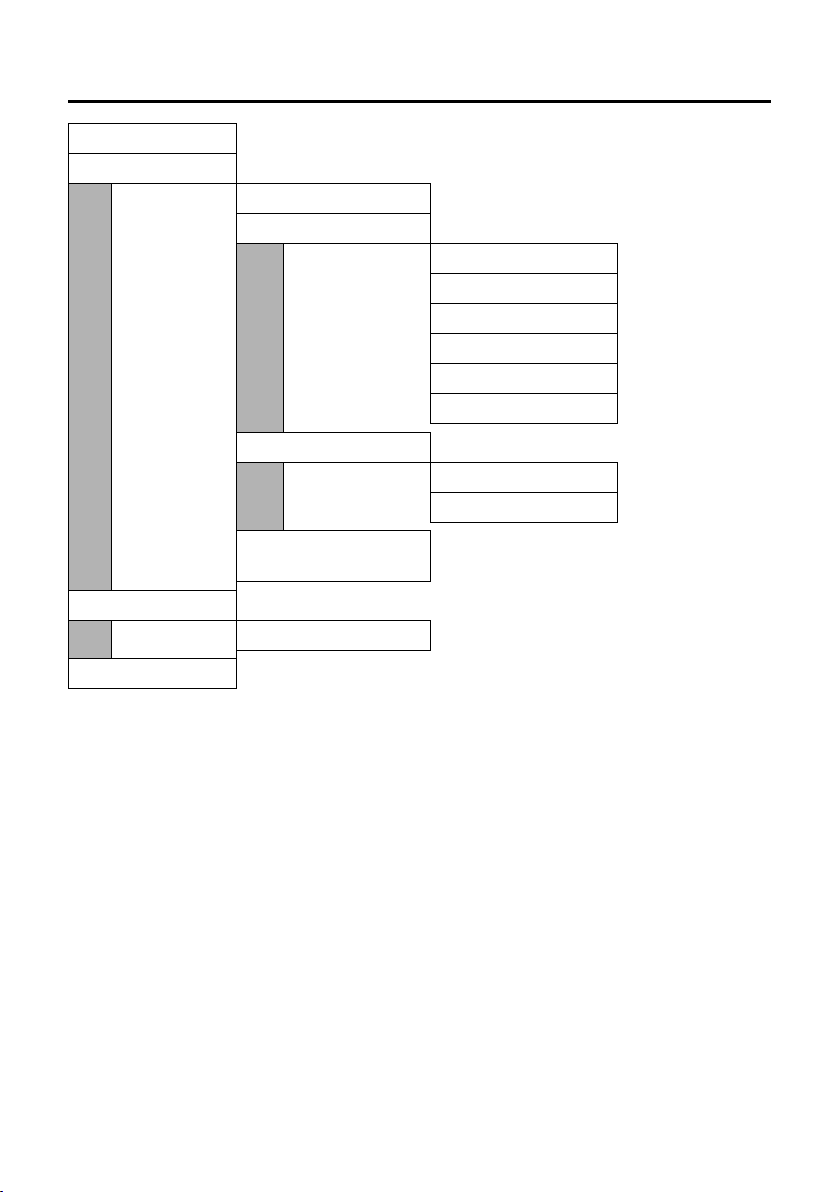
Phone Web configurator menu
Home page 65
Settings
IP Configuration page 87
Tel ephony
Connections page 90
Audio page 97
Number Assignment page 100
Dialing Plans page 103
Directory page 103
Advanced Settings page 101
Messaging
Messenger page 109
E-Mail page 111
Miscellaneous page 106,
page 107
Status
Device page 108
Router-Settings
connection to router Web configurator
page 69
27

Making an external call
Making calls
Making an external call
External calls are calls made via the Internet (VoIP).
¤ Enter the required number/IP address using the keypad.
¤ Press the talk key c.
Please note:
– You can specify for each handset registered to your base station which of your VoIP phone num-
bers (which VoIP account) should be used for outgoing external VoIP calls (page 100).
– If you use VoIP to make a call to the fixed network, you may also have to dial the area code for local
calls (depending on the VoIP provider). You can also enter the area code in the base station configuration so you do not always need to enter it for local calls (via the phone Web configurator,
page 103). It will then be inserted automatically for local calls.
Cancelling the dialling operation
You can cancel the dialling operation with the end call key a.
Entering an IP address
You can also enter an IP address instead of a phone number.
¤ Press the star key P to separate the sections of the IP address (e.g. 149*246*122*28).
¤ If necessary, press the # key to attach the SIP port number of the person you are call-
ing (page 144) to the IP address (e.g. 149*246*122*28#5060).
Please note:
– Dialling with the directory (page 40) or last number redial list (page 43) saves repeated keying of
phone numbers.
– You can assign a number from the directory to a key for speed dialling (page 41).
– You can edit or add to any phone number selected by means of speed dial or from the directory
and use it for the current call.
Ending a call
a Press the end call key.
28

Accepting a call
Accepting a call
The handset indicates an incoming call in three ways: by ringing, by a display on the screen
and by the flashing handsfree key d.
Please note:
The handset will indicate the following calls:
– Calls to receiving numbers that are assigned to this handset (page 100).
– Calls to receiving numbers that are not allocated as receiving numbers to any handsets.
You can accept the call by:
¤ Pressing the talk key c.
¤ Pressing the handsfree key d.
If the handset is in the charging cradle and the Auto Answer function is activated (page 53),
the handset will take a call automatically when you lift it out of the cradle.
If the ringer tone is intrusive, press
displayed on the screen.
Call display
When you receive an incoming call, the caller's number and/or the name they have specified is displayed on the screen.
If the caller's number is stored in your directory, the name from the directory will be displayed instead.
§Menu§ ¢ Silent. You can accept the call so long as it is
W
1234567890
For IP1
Menu§
1 Ringer icon (VoIP)
2 Number or name of caller (abbreviated if necessary).
If no number is transmitted, External Call will be displayed.
3 Receiving number: indicates which of your VoIP phone numbers the caller has dialled. You assign
the names when you enter the VoIP phone numbers into the phone (page 89). For calls from
Gigaset.net, For Gigaset.net is displayed.
1
2
3
29

Handsfree talking
Handsfree talking
In handsfree mode, instead of holding the handset to your ear you can stand it up or lay it
down, e.g. on the table in front of you, to allow others to participate in the call.
Activating/deactivating handsfree mode
Activating while dialling
~d Enter the number and press the handsfree key.
¤ You should inform your caller before you use the handsfree function so that they know
someone else is listening.
Switching between earpiece and handsfree mode
d Press the handsfree key.
Switch handsfree on and off during a call.
If you wish to place the handset in the charging cradle during a call:
¤ Press and hold the handsfree key d while placing the handset in the charging cradle. If
the handsfree key d does not light up, press the key again.
For how to adjust the loudspeaker volume, see page 53.
Muting the handset
You can deactivate the microphone in your handset during an external call. The other party
hears hold music.
Muting the handset
§INT§ Press the display key.
Cancelling muting
§Back§ Press the display key.
30

Activating/deactivating the handset
Operating the handset
Activating/deactivating the handset
a Press and hold the end call key.
You will hear the confirmation tone.
Activating/deactivating the keypad lock
# Press and hold the hash key.
You will hear the confirmation tone. The Ø icon appears in the display when the keypad
lock is activated.
The keypad lock deactivates automatically when you receive a call and activates again after
the call.
Please note:
If the keypad lock is activated and you accidentally press a key, an advisory message will be displayed
on the screen. Press and hold the hash key
Control key
§§§§INT§§§ §§Menu
# to deactivate the keypad lock.
1
1 Control key
In this user guide, the side of the control key that you must press in the given operating
situation is shown in black (top, bottom). Example: t for "press up on the control key".
The control key has a number of different functions:
When the handset is in idle status
t Adjust the ringer volume of the handset (page 54).
s Open the directory.
In lists and menus
t / s Scroll up/down line by line.
In an input field
t / s Move the cursor left or right.
31

Display keys
During an external call
s Open the directory.
t Adjust the loudspeaker volume for earpiece and handsfree mode.
Display keys
The current display functions are shown in the bottom display line in reversed highlights.
The function of the display keys changes depending on the particular operating situation.
Example:
§§§§INT§§§ §§Menu
1 Current display key functions
2 Display keys
The most important display symbols are:
§Back§ Go back one menu level or cancel the operation.
§INT§ Make an internal call (page 50).
§Menu§ Open the main menu or a context-dependent menu.
§OK§ Confirm highlighted selection.
˜ Delete key: deletes one character at a time from right to left.
1
2
Reverting to idle status
You wish to return to idle status from anywhere in the menu:
¤ Press and hold the end call key a.
Or:
¤ Do not press any key: after 2 minutes the display will automatically revert to idle status.
Changes that you have not confirmed/saved by pressing §OK§ will be rejected.
For an example of the display in idle status, see page 1.
32

Menu guidance
Menu guidance
Your telephone's functions are accessed using a menu that has a number of levels.
Main menu (first menu level)
¤ To open the main menu, press §Menu§ with the handset in idle status.
Accessing a function
¤ Scroll to the function with the control key q and press §OK§.
Or:
¤ Enter the number that is in front of the function in the menu tree (page 23).
The corresponding submenu (the next menu level) is opened.
Submenus
The functions in the submenus are displayed as lists.
To access a function:
¤ Scroll to the function with the control key q and press §OK§.
Or:
¤ Enter the number combination that is in front of the function in the menu tree
(page 23).
A short press on the end call key a returns you to the previous menu level / cancels the
operation.
Correcting incorrect entries
u Navigate to the incorrect input with the control key if û is displayed.
u Press ˜ to delete the character to the left of the cursor.
u Insert a new character to the left of the cursor.
u When entering the time and date etc., edit the flashing character.
You will find explanations for the symbols and typographical conventions used in this user
guide in the appendix, page 112.
33

Searching for subscribers in the Gigaset.net directory
VoIP telephony via Gigaset.net
You can use Gigaset.net to make free phone calls via the Internet directly to other
Gigaset.net users, without having to set up an account with a VoIP provider or make any
further settings. You simply have to connect your phone to the power supply and the Internet connection and, if necessary, enter yourself in the Gigaset.net online directory under a
name of your choice (page 20/page 36).
Gigaset.net is a VoIP service from Siemens Home and Office Communication Devices
GmbH and Co KG, which all users of a VoIP phone that supports Gigaset.net can use.
You can call other subscribers to Gigaset.net free of charge, i.e. there are no telephone
charges other than the costs for your Internet connection. Connections to/from other networks are not possible.
Every Gigaset VoIP device is assigned a Gigaset.net phone number by default (page 119).
All registered subscribers are included in the Gigaset.net directory, which you are able to
access.
An echo service is available on the phone number 1234#9 for you to check your VoIP con-
nection. After an announcement, the echo service sends back the voice data you have
received immediately in the form of an echo.
Exclusion of liability
Gigaset.net is a voluntary service provided by Siemens Home and Office Communication GmbH &
Co KG with no liability or guarantee for the availability of the network. This service can be terminated
at any time with a notice period of three months.
Please note:
If you do not use your Gigaset.net connection for six weeks, it is automatically deactivated. You
cannot be reached for calls from the Gigaset.net.
The connection is reactivated:
– as soon as you start a search in the Gigaset.net directory or
– make a call via the Gigaset.net (dial a number with #9 at the end) or
– activate the connection via the Web configurator (page 96)
Searching for subscribers in the Gigaset.net directory
Your handset is in idle status.
¤ Open the directory with the s button.
¤ Select the <Gigaset.net> entry and press the talk key c.
Please note:
– Calls to the Gigaset.net directory are always free of charge.
–If the <Gigaset.net> entry has been accidentally deleted from your handset directory, dial 1188#9
(the Gigaset.net directory phone number) and press the talk key c, or create a new directory
entry with this number.
34

Searching for subscribers in the Gigaset.net directory
Once the connection has been established, you will be asked to enter a name that you
want to search for.
Nickname:
Enter the name or part of a name (max. 25 characters).
§Menu§ Press the display key.
Start search
Select and press
§OK§.
If the search has been successful, a hit list will be displayed of all the names that begin with
the specified character string.
Example:
2/50
Sand, Anna Magd
alena
§View§ U §Menu
1. 2/50: Entry number/number of hits
2. Name of the entry, the name is displayed in full, if necessary over several lines
1
2
You can scroll through the hit list with q.
If it has not been possible to find a matching entry, a corresponding message is displayed.
You have the following options:
¤ Press the display key §New§ to start a new search.
Or
¤ Press the display key §Change§ to change the search criteria. The previously entered name
is copied and can be edited.
If there are too many matching entries in the Gigaset.net directory, the message Too many
entries found! is displayed instead of a hit list.
¤ Press the display key §Refine§ to start a refined search. The previously entered name is
copied and can be edited/expanded.
Calling subscribers
q Select the subscriber from the hit list.
c Press the talk key.
Viewing the subscriber's number
q Select the subscriber from the hit list.
§View§ Press the display key.
The Gigaset.net number and name will be shown in full, if necessary using more than one
line.
Please note:
You can open the Gigaset.net directory and establish connections, even if you have not entered
yourself in the Gigaset.net directory.
35

Searching for subscribers in the Gigaset.net directory
Using other functions
Precondition: The hit list is displayed.
q (Select entry)
The following functions can be selected with q:
Copy to Directory
Copy the number to the handset directory. The number and name (where appropriate
abbreviated, max. 16 characters) are copied to the directory.
¢ §Menu§
¤ Edit and save entry where appropriate (page 40).
The hit list is displayed again.
New search
Start a search with a new name (page 35).
Refine search
You can use the refined search to limit the number of hits for a previous search. The
name from the previous search is copied and can be edited/expanded.
Own information
See "Viewing, editing and deleting own entry" on page 36
Please note:
If you select a Gigaset.net number from the handset directory, the connection is automatically established via the Internet.
Viewing, editing and deleting own entry
You have the following options:
u Edit the name of your entry in the Gigaset.net directory.
u Delete your entry from the directory.
u If you did not enter a name when using the phone for the first time (page 20), specify
a name and enter yourself in the directory.
Viewing own entry
You are connected to the Gigaset.net directory:
¤ Select §Menu§ ¢ Own information and press §OK§.
Your Gigaset.net number and, where applicable, your currently entered name are
displayed.
36

Calling a Gigaset.net subscriber
Entering/editing a name
§Change§ Press the display key.
~ Edit name or enter new name (max. 25 characters) and press §OK§.
You can delete the name with ˜.
If there is not yet an entry with this name in the Gigaset.net directory, the name is saved.
A message to this effect is displayed. The handset switches to idle status.
If there is already an entry with this name, or the entered name contains impermissible
characters, you will be requested to enter a different name.
Please note:
If you delete the name, your entry will be deleted from the directory. You are no longer "visible" to
other Gigaset.net subscribers. However, you can still be reached via your Gigaset.net number. For
information on how to display the number, see page 119.
Calling a Gigaset.net subscriber
You can call a Gigaset.net subscriber directly via the Gigaset.net directory (see above) or
via their Gigaset.net number:
~ /s Enter the Gigaset.net number (including the #9) or select from the handset
directory.
c Press the talk key.
Every number ending with #9 is dialled via Gigaset.net.
37

Settings for all calls
Network services - VoIP
Settings for all calls
Call forwarding takes place locally in your base station.
Please note that call forwarding may incur additional costs. Ask your VoIP provider.
Setting up call forwarding
§Menu§ ¢ Select Services ¢ VoIP ¢ For All Calls ¢ Call Divert
A list of your phone's configured and activated VoIP phone numbers will be displayed. VoIP
phone numbers for which call forwarding is activated are identified with ‰.
Setting up call forwarding, changing the setting
q Select the VoIP phone number for which you want to activate or change call for-
warding and press
All Calls / No Answer / When Busy
Select and press
On Select and press §OK§.
~ If necessary, enter the number to which the call is to be forwarded. You can
enter a fixed network, VoIP or mobile number.
§OK§ Press the display key.
a Press and hold (idle status).
Call forwarding is activated for the selected VoIP phone number (receiving number).
§OK§.
§OK§ (‰ = on).
Deactivating call forwarding
q Select the VoIP phone number for which you want to deactivate call forwarding
and press
§OK§ Press the display key.
Off Select and press §OK§.
a Press and hold (idle status).
Call forwarding is deactivated.
§OK§.
Activating/deactivating call waiting
When call waiting is activated, the caller will hear the ringing tone if you are already making a call via your VoIP connection. This call is signalled acoustically and also shown on your
handset screen.
§Menu§ ¢ Select Services ¢ VoIP ¢ For All Calls ¢ Call Waiting
On/ Off Select and press §OK§.
a Press and hold (idle status).
38

Functions during a call
Functions during a call
The following functions are only available if you permit two parallel VoIP connections for
your telephone (see page 97, Allow 1 VoIP call only).
Consultation
During a VoIP call:
§Menu§ ¢ External Call
~ Enter the number or copy from the directory.
c Press the talk key.
The number will be dialled via the handset's VoIP sending number.
Please note:
– If the second VoIP connection is busy or there is no second VoIP connection available, you will hear
a busy tone and return to the first participant.
– After a few seconds, the number selected for a consultation call is saved in the last number redial
list.
– If the participant does not answer: press a. You are reconnected to the first participant.
If the participant answers, you have the following options:
u Toggli ng:
¤ Use q to toggle between the participants.
– End call with active participant:
u Conference call:
– Talk to both participants:
– End conference call (toggle):
– End call with both participants: Press the end call key a.
§Menu§ ¢ End Active Call.
§Menu§ ¢ Conference Call.
§Menu§ ¢ End Conference.
Accepting call waiting
Precondition: Call waiting is activated (page 38). You are making an internal call or a call
via VoIP.
§Menu§ ¢ Accept Call Waiting
If the first call was an internal call, the internal connection is ended.
If the first call was an external call, you can opt to toggle or hold a conference call.
Please note:
An internal call waiting is shown on the display. You can neither accept the internal call nor reject it.
39

Directory
Using the directory and lists
The options are:
u Directory
u Last number redial list
u Calls list
You can store up to 100 entries in the directory.
You can create a personalised directory for your own individual handset. However, you can
send the list or individual entries to other handsets (page 42).
Directory
In the directory you can store numbers and corresponding names.
¤ With the handset in idle status, open the directory by pressing the s key.
Length of an entry
Number: max. 32 digits
Name: max. 16 characters
Please note:
– Some VoIP providers do not support local calls for calls to the fixed network. In this case, always
enter the fixed network number with the area code in your directory.
Alternatively, you can also use the Web configurator to define an area code, which is automatically
prefixed to all numbers that are dialled without an area code for calls via VoIP (see Setting Area
Code Predialling, page 103).
– You can assign a number from the directory to a key for speed dialling (page 41).
Saving the first number in the directory
s ¢ Directory empty New Entry?
~ Enter the number and press §OK§.
~ Enter the name and press §OK§.
Please note:
To find out how to enter IP addresses, turn to page 28.
Storing a number in the directory
s ¢ §Menu§ ¢ New Entry
~ Enter the number and press §OK§.
~ Enter the name and press §OK§.
40

Directory
Selecting a directory entry
s Open the directory.
You have the following options:
u Use q to scroll to the entry until the required name is selected.
u Enter the first character of the name, or scroll to the entry with q.
Dialling with the directory
s ¢ q (select entry; page 41)
c Press the talk key.
Please note:
You can only dial IP addresses via VoIP.
Managing directory entries
You have selected an entry (page 41).
Editing entries
§Menu§ ¢ Edit Entry
~ Edit the number if required, and press §OK§.
~ Edit the name if required, and press §OK§.
Assigning a key
You can assign keys Q and 2 to O with a number. The number is then dialled by simply
pressing a key.
§Menu§ ¢ Shortcut
Assign the current entry for speed dial to a selected key.
Using other functions
s ¢ s (select entry; page 41) ¢ §Menu§
The following functions can be selected with q:
Use Number
Edit or add to a saved number. Then dial or use other functions with
Delete Entry
Delete selected entry.
Send Entry
Send a single entry to another handset (page 42).
Delete List
Delete all directory entries.
Send List
Send the complete list to another handset (page 42).
Using speed dial keys
¤ Press and hold the required speed dial key.
§Menu§.
41

Directory
Sending the directory to another handset
Preconditions:
u The sending and receiving handsets must both be registered on the same base station.
u The other handset can send and receive directory entries.
s ¢ q (select entry; page 41) ¢ §Menu§ ¢Send Entry / Send List
~ Enter the internal number of the receiving handset and press §OK§.
A successful transfer is confirmed by a message and confirmation tone on the receiving
handset.
If you have sent a single entry, you can transfer another entry with
§OK§.
Please note:
u Entries with identical numbers are not overwritten in the receiver handset.
u The transfer is cancelled if the phone rings or if the memory of the receiving handset is
full.
Copying a displayed number to the directory
You can copy numbers to the directory that are displayed in a list, e.g. the calls list or last
number redial list, to the directory.
A number is displayed.
§Menu§ ¢ Copy to Directory
¤ Complete the entry (page 40).
Copying a number from the directory
You can open the directory in many operating situations e.g. to copy a number. Your
handset need not be in idle status.
s Open the directory.
q Select an entry (page 41).
42

Last number redial list
Last number redial list
The last number redial list contains the ten numbers last dialled with the handset
(max. 32 numbers). If one of the numbers is in the directory, the corresponding name will
be displayed.
Open the last number redial list:
¤ With the handset in idle status, press the talk key c or handsfree key d.
Dialling from the last number redial list
c / d Open the last number redial list.
q Select an entry.
c / d Press the talk/handsfree key. The number is dialled
Managing entries in the last number redial list
c / d Open the last number redial list.
q Select an entry.
§Menu§ Press the display key.
The following functions can be selected with q:
Use Number
(as in the directory, page 41)
Copy to Directory
Copying a displayed number to the directory (page 42).
Delete Entry
(as in the directory, page 41)
Delete List
(as in the directory, page 41)
43

Opening lists with the message key
Opening lists with the message key
You can use the message key f to open the following lists:
u Network mailbox, see page 47
Preconditions: Your network provider supports this function and the network mailbox is
configured for fast access (page 47).
u Calls list
An advisory tone sounds as soon as a new message arrives in a list. The message key f
flashes. In idle status, the display shows an icon for the new message.
Icon New message...
Ã
Á
The number of new entries is shown beneath the corresponding icon.
When you press the flashing key f, you will see all the lists that contain new messages.
If only one list contains new messages, this will be opened automatically.
Please note:
If calls are saved in the network mailbox you will receive a message if the appropriate settings have
been made (see the network mailbox instructions of your VoIP provider).
Calls list
Depending on the type of list set, the calls list contains
u all incoming and outgoing calls
u missed calls only
The numbers of the last 30 calls are saved.
Multiple calls from the same number will be stored once in the list of missed calls (the latest
call).
Multiple calls from the same number are stored several times in the list of answered calls.
... in the network mailbox
... in calls list
Please note:
– Only calls to the receiving numbers assigned to a handset are stored in a handset's calls list
(page 100).
– If no receiving numbers are assigned, all calls will be stored in the calls list for all handsets.
The calls list is displayed as follows:
Calls List: 01+02
Number of new entries + number of old, read entries
44

Opening lists with the message key
Setting the calls list type
§Menu§ ¢ Settings ¢ Base ¢Calls List Type
Missed Calls / All Calls
Select and press
§OK§ (‰ =on).
a Press and hold (idle status).
The calls list entries are retained when you change the list type.
Opening the calls list
f ¢ Calls List: 01+02
q Select entry.
The last incoming call is displayed in the calls list.
List entry
Example of a list entry:
New Call 01/02
1234567890
11.01.07 19:27
§Back§ U §Menu
u Status of entry
In the calls list
New Call: new missed call.
Old Call: entry already read.
Call recv.: call taken.
u Entry number
01/02 means, for example: the first entry of a total of two entries.
u Number or name of caller
You can add the caller's number to the directory (page 42).
u Call date and time (if set, page 11).
Selecting from the calls list
f ¢ Calls List: 01+02
q Select entry.
c Press the talk key.
45

Opening lists with the message key
Managing entries in the calls list
f ¢ Calls List: 01+02
q Select entry.
§Menu§ Press the display key.
The following functions can be selected with q:
Delete Entry
As in the directory, page 41
Copy to Directory
Copy the number to the directory (page 42).
Show Name
If a URI (see page 145) was received and stored for a VoIP call, this will be shown. The
URI is dialled if you press the talk key c. The URI is not entered on the last number redial
list.
§OK§ / §Back§ to return to the list.
Press
Show Connection
Indicates which of your phone numbers the caller has dialled.
§OK§ / §Back§ to return to the calls list.
Press
Delete List
As in the directory, page 41
46

Configuring the network mailbox for fast access
Using the network mailbox
Some VoIP providers offer answer machines on the network – network mailboxes.
You can use the relevant network mailbox if you have requested it fro m your VoIP pro vider.
The network mailbox only answers incoming calls made via the relevant line (VoIP phone
number). To record all calls, you should therefore set up network mailboxes for each VoIP
phone number.
Configuring the network mailbox for fast access
With fast access you can dial a network mailbox directly.
The network mailbox is preconfigured for fast access. You only need to enter the number
of a network mailbox.
Please note:
You can only set up fast access to one of the network mailboxes. You can assign a speed dial number
to the number for another network mailbox in the directory (e.g. the
digit must be assigned for each handset.
Configuring the network mailbox for fast access and entering the network mailbox number
§Menu§ ¢ Voice Mail ¢ Set Key 1
Select Network Mailbox and press §OK§ (‰ = activated).
~ Enter the network mailbox number and press §OK§.
The entry is saved.
a Press and hold (idle status).
Fast access is automatically activated.
To deactivate fast access, you must delete the number.
This setting is now valid for all registered handsets.
2 key) (page 41). The speed dial
Please note:
If no number has been entered: press and hold 1 to enter the number.
Calling the network mailbox
1 Press and hold. You are connected straight to the network mailbox.
d If necessary, press the handsfree key. You hear the network mailbox announce-
ment.
Please note:
If you have set an automatic area code (page 103), the area code is also prefixed to the number of
the network mailbox if it does not start with 0.
Network mailbox message
The way in which you are informed of new messages in the network mailbox depends on
the relevant VoIP provider.
47

Registering handsets
Using several handsets
Registering handsets
You can register up to six handsets to your base station.
Please note:
After registration, all the phone numbers for the phone will be assigned to the handset as receiving
numbers. It uses the first VoIP number as sending numbers. For how to change the assignments, see
page 100.
Registering another Gigaset C46 handset
Before you can use your handset, you must register it to a base station.
You must initiate handset registration on the handset and on the base station.
If the handset has been registered successfully you will see the display key §INT§ at the
bottom left of the idle display. If it does not appear, repeat the procedure.
On the handset
Menu§ ¢ Settings ¢ Handset ¢Register Handset
~ Enter the system PIN of the base station (the default is 0000) and press §OK§.
The display shows e.g. Registering and Base flashes.
On the base station
÷ Within 60 sec. press and hold the registration/paging key on the base station
(page 1) (min. 1 sec.).
The handset is assigned the lowest available internal number (1-6). If several handsets are
registered to the base station, the internal number is shown in the display after registration, e.g. INT 2. This means that the handset has been assigned the internal number 2.
Please note:
If six handsets are already registered to the base station, there are two options:
– The handset with the internal number 6 is in idle status: the handset you wish to register is
assigned the number 6. The handset that was previously number 6 is de-registered.
– The handset with the internal number 6 is being used: the handset you wish to register cannot be
registered.
48

De-registering handsets
Registering other handsets
You can register other Gigaset handsets and handsets for other devices with GAP functionality as follows.
Please note:
Other handsets may not support all base station functions.
On the handset
¤ Start to register the handset as described in its user guide.
On the base station
÷ Press and hold (min. 1 sec.) the registration/paging key on the base station
(page 1).
De-registering handsets
You can de-register any registered C46 handset from any registered handset.
§INT§ Press the display key. All registered handsets are displayed.
q Select the handset to be de-registered.
§Menu§ Press the display key.
De-register Handset
Select and press
~ Enter the base station system PIN (default setting: 0000).
§OK§ Press the display key to confirm the prompt.
a Press and hold (idle status).
The handset is de-registered immediately, even if it is not in idle status.
§OK§.
Changing a handset's internal number
A handset is automatically assigned the lowest available number on registration. In the list
of internal subscribers, the handsets are sorted according to their internal number.
You can change the internal number of all registered handsets (1–6). Numbers 1-6 can
only be assigned once each.
§INT§ Press the display key.
§Menu§ Press the display key.
Edit Handset Number
Select and press
q Select handset.
~ Enter the number (1–6).
§OK§ Press the display key to complete the operation.
You will hear the error tone if an internal number has been allocated twice.
§OK§.
¤ Repeat the procedure with a free number.
49

Changing the name of a handset
Changing the name of a handset
The names "INT 1", "INT 2" etc. are assigned automatically at registration. You can change
these names. The changed name is displayed in every handset's list.
§INT§ Press the display key.
q Select handset.
§Menu§ Press the display key.
Change Handset Name
Select and press
~ Enter name (max. 10 characters) and press §OK§.
§OK§.
Locating a handset ("paging")
You can locate your handset using the base station.
¤ Press the registration/paging key on the base station (page 1) briefly.
¤ All handsets will ring simultaneously ("paging"), even if the ringer tones are switched
off.
Ending paging
÷ / c Briefly press the registration/paging key on the base station (page 1) or press
the talk key on the handset.
Making internal calls
Internal calls to other handsets registered on the same base station are free.
Calling a specific handset
§INT§ Press the display key.
qc Select handset and press the talk key.
Or:
~ Enter the number of the handset.
Calling all handsets ("group call")
§INT§ Press the display key.
P Press the star key.
Or:
Call All c Select and press the talk key.
Ending a call
a Press the end call key.
Please note:
You can reject an internal call by pressing the end call key a.
50

Making internal calls
Transferring a call to another handset
You can transfer an external call to another handset (connect).
§INT§ Press the display key.
The external participant hears the hold music.
q Select handset or Call All and press
When an internal participant answers:
§OK§.
¤ If necessary announce the external call.
a Press the end call key.
The call is transferred. If the internal participant does not answer, or their phone is in use,
the call will automatically return to you.
Internal consultation calls
When speaking to an external participant you can call an internal participant simultaneously for consultation.
§INT§ Press the display key.
The external participant hears the hold music.
q Select handset or Call All and press
If the internal participant does not answer: press §Back§ to return to the external participant.
When an internal participant answers you can speak to them.
You have the following options:
Ending a consultation call
§Menu§ Press the display key.
Back Select and press §OK§.
You are reconnected with the external participant.
§OK§.
Initiating a conference call
You are in an internal consultation call:
§Menu§ Press the display key.
Conference Call
Select and press
The internal participant called can end the conference call by pressing the end call key a.
§OK§.
Accepting call waiting during an internal call
If you receive an external call during an internal call, you will hear the call waiting tone
(short tone). With Calling Line Identification, the caller's number will appear in the display.
a Press the end call key to end the internal call.
c Press the talk key to take the external call.
51

Changing the display language
Handset settings
Your handset is preconfigured, but you can change the settings to suit your individual
requirements.
Changing the display language
You can view the display texts in different languages.
§Menu§ ¢ Settings ¢ Handset ¢Language
The current language is indicated by ‰.
q Select a language and press §OK§.
a Press and hold (idle status).
If you accidentally choose a language you do not understand:
§Menu§ ¢ 422
Press keys in sequence.
q Select the correct language and press
Setting the display
You have a choice of four colour schemes and several different contrasts. You can also set
a screensaver and backlight.
§Menu§ ¢ Settings ¢ Handset ¢Display
You have the following options:
Screensaver
There are four different screensavers and No Screensaver or Digital Clock settings.
Colour Scheme
There are four colour schemes. When the backlight is switched off, the display is shown
in black and white regardless of the selected setting.
Contrast
There are five different contrast settings.
Backlight
In Charger / Without Charger determines whether the backlight stays on permanently or is
switched off after a certain time (‰ = permanently switched on).
§OK§.
Please note:
If the backlight is switched on outside the charging cradle, the standby time for the handset is
considerably reduced!
52

Activating/deactivating auto answer
Activating/deactivating auto answer
When this function is activated, when a call arrives you can simply lift the handset out of
the charging cradle without having to press the talk key c.
§Menu§ ¢ Settings ¢ Handset
Auto Answer
Select and press
a Press and hold (idle status).
§OK§ (‰ =on).
Adjusting the loudspeaker volume
You can set the loudspeaker volume for handsfree talking to five different levels and the
earpiece volume to three different levels. You can only adjust the loudspeaker volume
during a call.
You are conducting an external call.
t Press the control key.
q Adjust the volume and press
Please note:
The handsfree volume can only be adjusted when this function is set.
If t is assigned a different function e.g. toggling (page 39):
§Menu§ Open menu.
Vol ume Select and press §OK§.
Make settings (see above).
§OK§.
Changing ringer tones
u Volume:
Five volume levels (1–5; e.g. Volume 2 = ˆ) and "crescendo" ring ‰.
With "crescendo" ring, the volume gets louder with every ring.
u Melody:
There is a list of pre-loaded ringer melodies. The first three melodies are the "classical"
ring tones.
You can also set different ringer melodies for the following functions:
u External Calls: for external calls
u Internal Calls: for internal calls
u Alarm Clock: for the alarm clock
53

Advisory tones
Setting the ringer volume
The ringer volume is the same for all types of ring.
§Menu§ ¢ Audio Settings ¢ Ringer Volume
Or in idle status:
t Press briefly.
Then:
q Adjust the volume and press §OK§.
a Press and hold (idle status).
Setting the ringer melody
Set different ringer melodies for external calls, internal calls and the alarm clock.
§Menu§ ¢ Audio Settings ¢ Ringer Melody
External Calls / Internal Calls / Alarm Clock
Select and press
q Select melody (‰ = on) and press §OK§.
a Press and hold (idle status).
§OK§.
Activating/deactivating the ringer tone
You can turn off the ringer tone on your handset before you take a call or while the phone
is in idle status. You can take a call so long as it is displayed on the screen.
Deactivating the ringer tone
P Press the star key and hold, until the Ú icon appears in the display.
Re-activating the ringer tone
P Press and hold the star key in idle status.
Advisory tones
Your handset uses "advisory tones" to tell you about different activities and statuses. You
can activate or deactivate the following tones:
u Advisory tones:
– Key click: every key press is confirmed.
– Confirmation beep (a rising tone sequence): at the end of the entry/setting, when
the handset is placed in the charging cradle and when a new entry arrives on the calls
list.
– Error tone (descending tone sequence): when you make an incorrect entry.
– Menu end tone: when scrolling at the end of a menu.
u Battery low beep: the battery requires charging.
You cannot deactivate the confirmation tone for placing the handset in the charging
cradle.
54

Using the handset as an alarm clock
Activating/deactivating advisory tones
§Menu§ ¢ Audio Settings ¢ Advisory Tones
Select and press
All advisory tones are activated or deactivated.
§OK§ (‰ =on).
Setting the battery low beep
§Menu§ ¢ Audio Settings ¢ Battery Low
On / Off / During Call
Select and press
The battery low beep is activated or deactivated or sounds during a call.
§OK§ (‰ =on).
Using the handset as an alarm clock
Activating/deactivating the alarm clock
§Menu§ ¢ Alarm Clock ¢ Activation (‰ =on)
After you activate the alarm clock, the menu for setting the wake up time opens automatically (page 55).
If the alarm clock is set, the wake up time appears with the l icon in the display instead of
the date.
Setting the wake up time.
§Menu§ ¢ Alarm Clock ¢ Wake up time
~ Enter the wake up time in hours and minutes, then press §OK§.
When the alarm clock rings…
Alarm repeat after 5 minutes
§Snooze§ Press the display key or any key.
If you press §Snooze§ three times the alarm clock switches off for 24 hours.
Turning off the alarm clock for 24 hours
§Off§ Press the display key.
55

Restoring the handset to the factory settings
Restoring the handset to the factory settings
Each individual handset setting is reset, in particular the language, display, volume, ringer
and alarm clock settings (see from page 52 onwards). The last number redial list is cleared.
Entries in the directory, the date and time, and the handset's registration to the base
station will be retained.
§Menu§ ¢ Settings ¢ Handset ¢Reset Handset
§OK§ Press the display key to confirm.
a Press and hold (idle status).
Cancel the reset with a.
Setting the base station
The base station settings are carried out using a registered Gigaset C46 handset.
Changing the system PIN of the base station phone
You will have to enter the system PIN e.g. when you register a handset with the base
station, change the VoIP settings or start the phone Web configurator.
You can change the base station's 4-digit default system PIN ("0000") to a 4-digit PIN
known only to yourself.
§Menu§ ¢ Settings ¢ Base ¢System PIN
~ Enter the current system PIN and press §OK§.
~ Enter your new system PIN and press §OK§.
~ Now re-enter the new system PIN and press §OK§.
For security reasons, "
a Press and hold (idle status).
" is displayed instead of the numbers entered.
****
Restoring the base station to the factory settings
The base station's phone and router will be reset.
Please note:
You should carry out the following base station resets before giving your base station to a third party.
This will delete your personal data.
56

Activating/deactivating the on hold music
Resetting the base station via the menu
Each individual setting is reset, in particular:
u all router settings
u the router password
u VoIP settings such as VoIP provider and account data (page 61, page 90) and DTMF
settings (page 101)
u settings for the local network (page 59, page 87)
u the names of the handsets (page 50)
The calls list is cleared.
The date and time and the system PIN are retained. The handsets are still registered.
§Menu§ ¢ Settings ¢ Base ¢Base Reset
§OK§ Press the display key to confirm.
Resetting the base station using a key on the base station
As with resetting the base station via the menu, each individual setting on the base station
phone is reset. The system PIN will also be reset to "0000" and all handsets registered
above and beyond the delivery scope are deregistered.
The router settings and router password are not reset.
Please note:
For how to reregister the handsets after resetting if necessary, see page 48.
¤ Remove the cable connection between the base station and modem.
¤ Remove the Ethernet cable from the base station's LAN socket.
¤ Remove the base station mains unit from the socket.
¤ Press and hold the registration/paging key (page 1).
¤ Plug the mains unit back into the power socket.
¤ Press and hold the registration/paging key (at least 10 sec.).
¤ Release the registration/paging key. The base station has now been reset.
Activating/deactivating the on hold music
§Menu§ ¢ Settings ¢ Base
Music on hold
Select and press
Please note:
Whether or not a caller hears the hold music during toggling or a consultation call depends on the
provider.
§OK§ to activate or deactivate the hold music (‰ =on).
57

Activating/deactivating repeater mode
Activating/deactivating repeater mode
With a repeater you can increase the range and reception strength of your base station. You
will need to activate repeater mode. This will terminate any calls being made via the base
station at that time.
Precondition: A repeater is registered.
§Menu§ ¢ Settings ¢ Base ¢Additional Features ¢ Repeater Mode
Select and press
§OK§ (‰ =on).
Updating the base station phone's firmware
If necessary, you can update your base station phone's firmware.
The firmware update is downloaded directly from the Internet by default. The relevant
website is preconfigured in your phone.
As an alternative to uploading the firmware via the Internet, it can also be loaded from a
local PC. You can specify the PC via the phone Web configurator (page 106). This setting
applies only to the next firmware update.
Precondition:
The base station is in idle status, i.e.:
u no calls are being made.
u there is no internal connection between the registered handsets.
u no other handset has opened the base station menu.
Starting the firmware update manually
§Menu§ ¢ Settings ¢ Base ¢Firmware Update
~ Enter the base station system PIN (default setting: 0000).
The base station establishes a connection to the Internet or to the local PC.
§Yes§ Press the display key to start the firmware update.
Please note:
– A firmware update can last up to 3 minutes. During the update, the handset loses the connection
to the base station. When the update has been successfully completed, the handset re-establishes
the connection to the base station.
– When updating from the Internet, checks are made to ensure that no newer version of the
firmware exists. If this is not the case, the operation is terminated and a message is issued to that
effect.
– If an error arises during a firmware update from a local PC, the most recent version of the firmware
is automatically downloaded from the Internet. Your phone should therefore be connected to the
Internet during every firmware update.
58

Setting the base station phone's IP address in LAN
Automatic firmware update
Precondition: The automatic version check is activated (page 107, default setting).
Your phone will check daily whether a newer firmware update is available via the Internet
on the Siemens configuration server. If this is the case, when the handset is in idle status
the message New firmware available! is displayed and the message key f flashes.
f Press the message key.
§Yes§ Press the display key to confirm the prompt.
~ Enter the base station system PIN (default setting: 0000).
The firmware will be loaded onto your phone.
Please note that the firmware update may take up to 3 minutes.
Please note:
– If you reply to the request with §No§, the display will not be repeated. The message New firmware
available! will only be shown again if a newer version of the firmware than the one rejected is
available.
– You can deactivate the automatic version check via the Web configurator (page 107).
Making VoIP settings
For VoIP telephony you need to make the following settings:
u IP settings for the telephone connection to the LAN (to the router). You can make these
settings on the handset (page 59) or (if there is already a connection to the PC) via the
phone Web configurator (page 87).
u VoIP settings for each of your VoIP accounts (VoIP phone numbers). You can make the
settings for up to six VoIP accounts via the Web configurator.
Alternatively, you can also set and make changes to the first VoIP account (IP1, see
page 89) via the handset. You can make the settings with (page 61) or without
(page 61) connection assistants.
Setting the base station phone's IP address in LAN
The base station requires an IP address in order to be "recognised" by the LAN (the router).
The IP address can be assigned to the base station automatically (by the router) or manu-
ally.
u If performed dynamically, the router's DHCP server automatically assigns the base
station an IP address. The base station's IP address can be changed according to router
settings.
u If performed manually, you assign the base station a static IP address. This may be nec-
essary depending on your network configuration.
Please note:
For how to make the local network settings on the Web configurator, turn to page 87.
59

Setting the base station phone's IP address in LAN
Activating/deactivating dynamic assignment
§Menu§ ¢ Settings ¢ Base ¢Local Network
~ Enter the system PIN and press §OK§.
dynamic IP address (‰ =on)
Select and press
If you deactivate dynamic assignment, you must set the base station, default gateway and
DNS server IP address and subnet mask manually. A corresponding message is displayed.
§OK§ to change the current settings.
Please note:
To assign the IP address dynamically, the DHCP server on the router must be activated (page 80).
Viewing/changing the phone's IP address
You can only change the IP address (page 140) if you have deactivated dynamic assignment.
192.168.1.2 has been preset by default.
§Menu§ ¢ Settings ¢ Base ¢Local Network (enter system PIN) ¢ IP Address
The current IP address is displayed.
~ If necessary, enter the IP address and press §OK§.
Please note:
For notes on the IP address, please see page 87 and the glossary on page 140.
Viewing/changing the subnet mask
You can only change the subnet mask (page 144) if you have deactivated dynamic assignment.
255.255.255.0 has been preset by default.
§Menu§ ¢ Settings ¢ Base ¢Local Network (enter system PIN) ¢ Subnet Mask
The current subnet mask is displayed.
~ If necessary, enter the subnet mask and press §OK§.
Please note:
For notes on the subnet mask, please see page 87 and the glossary on page 144.
60

Entering/changing the first VoIP account with the connection assistant
Viewing/changing the DNS server
Enter the IP address for the preferred DNS server. The DNS server (Domain Name System)
converts the symbolic name of a server (DNS name) into the public IP address for the server
when the connection is made.
You can specify your base station router's IP address here. The router forwards phone
address requests to its DNS server.
The default is 192.168.1.1.
§Menu§ ¢ Settings ¢ Base ¢Local Network (enter system PIN) ¢ DNS Server
~ If necessary, enter the IP address of your preferred DNS server and press §OK§.
Viewing/changing the default gateway to the Internet
Enter the IP address for the standard gateway, by means of which the local network is connected with the Internet. That is usually the local (private) IP address for your base station
router (default 192.168.1.1). Your phone requires this information to be able to access the
Internet.
The default is 192.168.1.1.
§Menu§ ¢ Settings ¢ Base ¢Local Network (enter system PIN) ¢ Default Gateway
Entering/changing the first VoIP account with the connection assistant
The connection assistant starts automatically the first time your handset and base station
are used. You can also start the connection assistant via the menu:
§Menu§ ¢ Settings ¢ Base ¢Telephony ¢Connection Assistant
For how to enter VoIP settings for the first VoIP account using the connection assistant, see
page 18.
Entering/changing the first VoIP account without the connection assistant
For your first account you can change your provider's general VoIP settings and your personal VoIP user data via the menu without starting the connection assistant.
Downloading settings for the first VoIP provider
§Menu§ ¢ Settings ¢ Base ¢Telephony ¢VoI P (enter system PIN) ¢ Select VoIP Provider
The phone establishes a connection with the Siemens configuration server on the Internet.
q Select country and press §OK§.
q Select VoIP provider and press §OK§.
Your VoIP provider data is downloaded and saved in your phone.
If errors occur during a download, see page 113.
61

Entering/changing the first VoIP account without the connection assistant
Please note:
If your VoIP provider is not included in the list, you need to enter or adjust the general VoIP settings
manually via your phone's Web configurator, see page 92.
Automatic update for the VoIP provider settings
Precondition: The automatic version check is activated (page 107, default setting).
After the first download of the VoIP provider settings, your phone will check daily whether
a newer version of the files for your VoIP provider is available via the Internet on the
Siemens configuration server. If there is an update for one of your VoIP providers, the
message New profile available! will be displayed when the handset is in idle status, and the
message key f flashes.
f Press the message key.
§Yes§ Press the display key to confirm the prompt.
~ Enter the system PIN and press §OK§.
The new VoIP provider data is downloaded and saved in your phone.
Please note:
– The version check relates to all VoIP providers whose data you have downloaded from the Internet.
– If you reply to the request with §No§, the display will not be repeated. The message New profile
available! will only be shown again if a newer version of the VoIP settings than the one rejected is
available.
– You can deactivate the automatic version check via the Web configurator (page 107).
Entering/changing the VoIP user data for the first VoIP account
The VoIP settings must also be extended for your personal data. You will receive all necessary data from your VoIP provider.
Please note:
When making these entries, please remember the VoIP user data is case sensitive. For how to enter
text see page 124.
§Menu§ ¢ Settings ¢ Base ¢Telephony ¢VoI P
~ Enter the system PIN and press §OK§.
Username / Authentication Name / Authentication Password
Select and press
~ Enter/change the user data and press §OK§.
Enter the caller ID for your VoIP provider account as the Username. The Username is mainly
identical to your Internet phone number (the first part of your SIP address see page 91).
For Authentication Name and Authentication Password enter the provider-dependent access
data that has to be transferred by the phone to the SIP service at registration.
Tip: A previously set password is not displayed.
62
§OK§.

Activating/deactivating display of VoIP status codes
Activating/deactivating display of VoIP status codes
If the function is activated, a VoIP status code for your service provider is displayed.
Activate the function e.g. if you have problems with VoIP connections. You will receive a
provider-specific status code, which supports the service when the problem is analysed.
§Menu§ ¢ Settings ¢ Base ¢Telephony ¢VoI P
~ Enter the system PIN and press §OK§.
Status on HS (‰ =on)
Select and press
§OK§.
Please note:
– For how to make the setting on the Web configurator, see page 108.
– A table with possible status codes and their meaning can be found in the appendix on page 116.
Checking the base station phone's MAC address
Depending on your network configuration, you may have to enter your base station
phone's MAC address, for example,into your router's access control list. You can check your
base station phone's MAC address:
§Menu§ ¢ 4IO2Q
Your base station phone's MAC address will be displayed.
a Press and hold (idle status).
63

Configuring the base station router and phone via a PC
Using the Web configurators
You can manage your Gigaset CE 460 IP R via your PC's Web browser with two Web
configurators:
u Use the router Web configurator to make the settings for your base station router.
u Use the phone Web configurator for the settings for your base station phone.
Please note:
Depending on your VoIP provider, it is possible that you will be unable to change individual settings
in the Web configurator.
Configuring the base station router and phone via a PC
Preconditions:
u A standard Web browser is installed on the PC, e.g. Internet Explorer version 6.0 or
higher, or Firefox version 1.0.4 or higher.
u The base station and PC are connected to each other.
Please note:
–The phone is not locked while you make settings for one of the Web configurators. You can also
use your phone to make calls or change base station or handset settings on your handset at the
same time.
– While you are connected to the Web configurator, it is blocked to other users. It cannot be accessed
by more than one user at any time.
The router Web configurator offers the following options:
u Start the wizard for the basic router settings and the connection to the Internet
u Configure your router access to the local network (IP address, gateway to the Internet).
u Define the data server for firmware updates and load new firmware onto the router if
necessary.
u Obtain information about your router's status (firmware version, MAC address andso
on).
The phone Web configurator offers the following options:
u Configure your phone access to the local network (IP address, gateway to the Internet).
u Configure your phone for VoIP.
u Define the data server for firmware updates and load new firmware onto the phone if
necessary.
u Copy contacts from the Outlook address book on your PC into the handset directories or
back up your handset's directories on your PC.
u Obtain information about your phone's status (firmware version, MAC address andso
on).
64

Starting the Web configurator
Starting the Web configurator
Precondition: The settings of an available firewall allow the PC and base station to communicate with each other.
You need to establish a connection with the PC Web browser to the respective Web configurator (router Web configurator or phone Web configurator) to be able to access the functions of both Web configurators.
Once you have successfully established the connection, the Web browser will display a Web
pa ge fo r regi stration a nd this will ask y ou to authenticate yourself by entering a system PIN.
The Home for the selected Web configurator will be displayed once you have registered successfully.
You can find the detailed description of the start and registration procedure on page 69
(router Web configurator) or page 85 (phone Web configurator).
Please note:
– The base station router and the base station phone have passwords or system PINs that are inde-
pendent of one another. Changing the password for the base station router will not affect the system PIN for the phone and vice versa.
– If you have forgotten your password or your system PIN, you will have to reset your base station
to the factory settings. Please note that this will restore all other settings too (page 57).
– If you do not make any entries for a lengthy period (around 10 minutes), you will be automatically
logged off. The next time you try to make an entry or open a Web page, the Login Web page will
be displayed. Enter the system PIN again to log in again.
– Entries that had not yet been saved in the router or on the phone before automatic log-off are lost.
Logging off
In the menu bar at the top right of every Web page in the Web configurator, you will see
the Log Off command (page 66). Click Log Off to log off from the Web configurator.
Warning:
Always use the Log Off command to end the connection to the Web configurator. If, for example, you
closethe Web browser without logging off first, it is possible that access to the Web configurator will
be blocked for a few minutes.
65

Structure of the Web pages
The Web pages contain the UI elements displayed in Figure 2.
Working areaNavigation area Menu barButtons
Figure 2 Example of the structure of a Web page
Structure of the Web pages
Menu bar
In the menu bar, the Web configurator menus are depicted in the form of tab pages.
The following menus are available in this example:
u Home
u Settings
u Status
If you click a menu that contains subfunctions (in this example the Settings menu), then
these will be displayed in the navigation area.
You wil l find the Log Off function to the right of the menu bar on every Web page (page 65).
Please note:
You will find an overview of the Web configurator menu on page 27.
66

Structure of the Web pages
Navigation area
The functions of the menu selected in the menu bar are listed in the navigation area.
If you click a function, the associated page opens in the working area with information and/
or fields for your inputs.
If a function is assigned subfunctions, these are displayed with the function as soon as you
click the function. The relevant page for the first subfunction is displayed in the working
area.
Working area
Depending on the function selected, information or dialogue boxes are displayed in the
working area, which allow you to make or change your phone settings.
Making changes
Make settings for entry fields, lists or options.
u There may be restrictions regarding the possible values for a field, e.g. entering special
characters or certain value ranges.
u To open a list, click . You can choose between default values.
u There are two kinds of options:
– Options in a list, from which you can activate one or several options. Active, i.e.
selected options are highlighted with , non-active options with . You can acti-
vate an option by clicking on . The status of the other options in the list does not
change. You can deactivate an option by clicking on .
– Alternative options. The active option in the list is highlighted with , and the non-
active with . You can activate an option by clicking on . The previously activated
option is deactivated. You can only deactivate an option by activating another option.
Applying changes
As soon as you have made your change on a page, activate the new setting in the router or
on the phone by clicking on Set.
If your input in a field does not comply with the rules for this field, an appropriate error
message will be displayed. You can then repeat the input.
Warning:
Changes that have not been saved in your router or phone are lost if you move to another Web page
or if the connection to the Web configurator is terminated, e.g. due to exceeding the time limit
(page 65).
67

Opening Web pages
Buttons
Buttons are displayed in the bottom section of the working area.
Set
Save entries on the phone.
Cancel
Reject changes made on the Web page and reload the settings that are currently saved
in your phone to the Web page.
Opening Web pages
A brief outline of the navigation to the individual Web configurator functions is given
below.
Example:
Setting DTMF signalling with the phone Web configurator
Settings ¢ Telephony ¢ Advanced Settings
To open the Web page, carry out the following steps after registration:
¤ Click the Settings menu in the menu bar.
¤ Click the Telephony function in the navigation area.
The subfunctions of Telephony are displayed in the navigation tree.
¤ Click the Advanced Settings subfunction.
The Web page from Figure 2 will be shown in the Web browser.
68

Connecting the PC to the router Web configurator
Router Web configurator
You can use the router Web configurator to configure the base station router.
u Save your Internet access data (page 71) and the address for your DNS server (page 78)
on your router.
u Activate and configure NAT (page 75) and firewall for the router (page 74).
u Activate the Quality of Service for the router (page 78).
u Activate/deactivate the DHCP server for your router (page 80).
u Select the time server and time zone (page 81).
u Make the settings for the remote management of the router (page 82) and change the
router password (page 82).
u Load the firmware updates onto the router.
Connecting the PC to the router Web configurator
Precondition: The settings of an available PC firewall allow the PC and base station to communicate with each other.
¤ Launch the Web browser on your PC.
¤ In the Web browser address field, enter the IP address or name of the base station
router, e.g.
http://192.168.1.1 or http://router.gigaset (default setting)
¤ Press the return key.
A connection is established to the base station router's Web configurator.
Please note:
You can find out how to change the name router.gigaset on page 81.
Login
Once you have successfully established the connection, the Login Web page will be
displayed in the Web browser.
The language in which the menus and the dialogues for the router Web configurator are
displayed is preset by the firmware.
¤ Enter the password for your base station router in the bottom field of the Web page
(default setting: 0000) to access the router Web configurator functions.
¤ Click OK.
Once you have successfully logged in, a Home opens with general information on the Web
configurator.
69

Login
Please note:
– If you have forgotten your password or your system PIN, you will have to reset your base station
to the factory settings. Please note that this will restore all other settings too (page 57).
– If you do not make any entries for a lengthy period, you will be automatically de-registered. The
next time you try to make an entry or open a Web page, the Login Web page will be displayed.
Enter the system PIN again to log in again. This time is set to 30 min. in the default settings. You
can change it (page 82).
– Entries that had not yet been saved before automatic log-off are lost.
Menu bar
The following menus are available in the router Web configurator:
u Home
The start screen is opened once you have registered with the Web configurator. It contains information on the Web configurator menus.
u Basic Setup Wizard (page 85)
You can start a wizard to connect the base station router to the Internet via this menu
(page 15).
u Router Settings (page 69)
This menu allows you to make settings on your base station router. The Router Settings
menu comprises the function areas Internet, Local Network and Administration.
u Telephony Settings
You can use this menu to start the phone Web configurator (page 85), to make settings
on the base station phone.
u Status (page 84)
This menu gives you information about your phone.
70

Internet – configuring the connection to the Internet.
Internet – configuring the connection to the Internet.
If you have configured the router for your Gigaset CE 460 IP R using the wizard for the basic
settings, then you will also have configured the WAN connection (Internet access). You can
check, change or extend these settings in the Internet menu.
Under Internet you can also find functions for security settings and limiting access to the
Internet as well as for providing your own services on the Internet.
You can use the Internet menu to make the following settings for the Internet:
u check and edit the Internet access data (page 71),
u secure your local network against external hacker attacks and restrict access to Internet
pages for subscribers in the local network (see Firewall, page 74),
u provide your own services on the Internet and restrict access from the Internet to the
local network (see NAT, page 75),
u enter addresses for the DNS server used (page 78),
u define QoS properties (Quality of Service, see page 78), i.e. prioritise the transfer of
VoIP data and thus improve the voice quality for VoIP connections.
Connection – entering access data for the Internet connection
You can use the Connection Web page to set up or change the configuration for your Inter-
net connection. Any settings that you make here must correspond with the information
from your Internet provider. False information can lead to problems with your Internet connection.
The procedure for entering or changing the settings for Internet access is as follows:
¤ Open the following Web page: Router Settings ¢ Internet ¢ Connection.
The settings for the Internet connection that are currently stored in the base station will
be displayed.
¤ First select the WAN connection type from the Connection list. The connection type
depends on what kind of Internet connection you have and the agreements with your
Internet provider. The access data received from your Internet provider for registration
shows you which connection type you must select.
The options are PPPoE, Static IP Address, Dynamic IP Address and PPTP.
¤ Enter the access data required for the connection type (see below).
¤ In the Upstream Rate field, enter the maximum amount of your Internet connection's
bandwidth that should be available for data uploads. First enter the upload stream rate
given by your Internet provider. Carry out tests to check that calls can also be made with
good voice quality at the same time as data is being uploaded and adjust the rate
accordingly (page 78).
¤ Click Set to apply the settings.
¤ Below is an explanation of the information that you must make dependent on
Connection:
71

Connection – entering access data for the Internet connection
Connection = PPPoE
The protocol PPPoE (Point-to-Point-Protocol over Ethernet) is used by many Internet providers. It allows several subscribers in a local network to access the Internet via a single Internet account. The Internet provider assigns your router a password and, if necessary, a user
name.
User Name
If you have received a user name from your Internet provider, enter this name
here. Not all Internet providers require a user name. If this is the case, leave this
field empty.
Password, Confirm new password
In the Password field, enter the password agreed with the Internet provider and
repeat it in the Confirm new password field.
MTU The MTU (Maximum Transmission Unit) defines the maximum length of a data
packet that can be carried over the Internet at one time. The standard value is
1492 bytes. Depending on the provider, there may be restrictions for the packet
size. You should then modify the value accordingly.
Please note:
For the Internet connection via PPPoE, your router is set so that it is permanently connected with the
Internet. This means that you can always be reached for VoIP calls.
Connection = Static IP Address
A static IP address is assigned to the router. This is permanently assigned to your router as
a public IP address (page 142). The router needs the following data for the Internet access:
IP Address, Subnet Mask
Enter the static IP address and subnet mask given to the router by your Internet
provider.
If the base station router is connected to the Internet via another local network
(LAN), then enter the private IP address for your router in this LAN and the subnet mask for the LAN.
Gateway Enter the IP address of the gateway that connects your router with the Internet.
If the connection is via another LAN, enter the private IP address for the router
or gateway that is used to connect this LAN with the Internet here.
72

Connection – entering access data for the Internet connection
Connection = Dynamic IP Address
The router is assigned an Internet address dynamically. This IP address is only temporarily
assigned to the router. It can change. No more data must be entered for this connection
type.
This connection type is frequently used for Internet connection via another LAN.
The following data is displayed on the Web page:
IP Address, Subnet Mask
The IP address that is currently assigned to the router, and the corresponding
subnet mask.
Gateway The IP address for the router or gateway computer that connects the router to
the Internet.
DHCP Server
The IP address server that assigns the IP address to the router.
Connection = PPTP
The PPTP protocol (Point-to-Point Tunnelling Protocol) allows a secure connection to a
remote private network (e.g. from home to your company network) via the Internet. Your
router is part of a Vir tua l Priv ate Netwo rk (VP N). The data is sent via th e Inte rnet i n a secure
and encrypted connection (tunnel).
The following data is required for access to the remote network:
IP Address, Subnet Mask
Enter the IP address and subnet mask given to the router by your Internet provider.
Gateway Enter the IP address of the gateway that connects your router with the Internet.
VPN Server Enter the IP address of the VPN server (Virtual Private Network). The VPN server
is the gateway to the remote network. Your Internet provider will supply you
with the IP address.
User Name
Enter the user identification that your router must enter when logging on to
the remote network.
Password, Confirm new password
In the Password field, enter your registration password and repeat it in the
Confirm new password field.
MTU The MTU (Maximum Transmission Unit) defines the maximum length of a data
packet that can be carried over the Internet at one time. The standard value is
1492 bytes. Depending on the provider, there may be restrictions for the packet
size. You should then modify the value accordingly.
73

Setting up the Firewall
Setting up the Firewall
Your router's integrated firewall monitors and limits the exchange of data between subscribers of your local network and the Internet. Activating the firewall does not affect the
router's performance.
When the firewall is activated you can:
¤ protect your network against hacker attacks,
¤ restrict Internet access for individual PCs in your local network (IP Filter, MAC Filter).
The firewall functions are activated and configured by default. Do the following to change
the settings for the firewall:
¤ Open the following Web page: Router Settings ¢ Internet ¢ Firewall.
¤ Highlight On or Off in the Firewall field to activate or deactivate the firewall.
¤ Click Set to apply the settings.
Attack Detection
When the firewall is activated, you can also switch attack detection on or off.
¤ Highlight the desired setting in the Attack Detection field.
¤ Click Set to apply the settings.
IP Filter
When the firewall is activated, you can restrict access to the Internet for certain PCs in your
local network based on their IP address.
Create a list of the PCs and the applications (defined by their port number on the PC) that
you want to allow access to the Internet.
¤ Open the following Web page: Router Settings ¢ Internet ¢ Firewall ¢ IP Filter.
¤ Enter the IP address of the PC in the IP Address field.
¤ In the Port Range fields, enter the first and last port number of the port area on the PC
that you do not want to have access to the Internet.
¤ Select the protocol used from the Protocol list and click Add.
¤ Repeat the previous step if there are further PCs or applications that you do not want to
allow access to the Internet.
¤ Click Set to apply the settings.
Please note:
– Deactivate the Enabled field to give a specified PC temporary access.
– Click Delete to permanently remove a PC from the list.
74

Setting up NAT
MAC Filter
When the firewall is activated, you can restrict access to the Internet for certain PCs and PC
applications based on their MAC address.
¤ Open the following Web page: Router Settings ¢ Internet ¢ Firewall ¢ MAC Filter.
¤ In the fields for MAC Address, enter the MAC address for the PC that you do not want to
have access to the Internet and click on Add.
¤ Repeat the previous step if there are further PCs that you do not want to allow access to
the Internet.
¤ Click Set to apply the settings.
Please note:
– Deactivate the Enabled field to give a specified PC temporary access.
– Click Delete to remove a PC from the list.
Setting up NAT
NAT (Network Address Translation) allows several subscribers (PCs) in their local network
to access the Internet via a public IP address. NAT also protects the subscribers in their local
network against direct unauthorised access from the Internet.
They can, however, forward requests from the Internet specifically to PCs or applications in
their local network if they use special applications, or if they operate a server in their local
network (Port Forwarding / Exposed Host).
Activating/deactivating NAT:
¤ Open the following Web page: Router Settings ¢ Internet ¢ Address Translation (NAT).
¤ Highlight On or Off in the Address Translation (NAT) field to activate or deactivate NAT.
¤ Click Set to apply the settings.
If NAT is activated, the following functions are displayed in the navigation tree for the NAT
configuration, and these can be used to control communication between the local network
and the Internet:
u Port Forwarding (page 76),
u Port Mapping (page 77),
u Exposed Host (page 77) and
u UPnP (page 78)
75

Setting up NAT
Port Forwarding
Port forwarding enables you to make services from applications in your local network available to Internet users as well. The router can use a specific port to automatically forward
incoming requests from the Internet to a PC in the local network and thus set up a virtual
server, for example to publish your Internet page on your own Web server.
Internet services are generally addressed via defined port numbers. The router requires a
mapping table for the port numbers in order to divert the service requests to a PC that
actually provides the service. You can create these on this Web page.
Precondition: NAT is activated.
¤ Open the following Web page: Router Settings ¢ Internet ¢ Address Translation (NAT)
¢ Port Forwarding.
¤ Select a service from the Predefined Applications list.
¤ In the Local IP Address column, enter the private IP address for the PC to which the
requests should be forwarded and click Add.
¤ Repeat the previous step as necessary for further port forwarding.
If the required service is not in the list, you will have to enter the port forwarding manually.
¤ Select the protocol used by the service from the Protocol list.
¤ Enter the port number for the service under Public Port.
¤ Under Local Port enter the number ports on the PC to which the service requests should
be forwarded.
¤ Enter the IP address for the PC in the local network in the Local IP Address field.
¤ Repeat the previous step as necessary for further port forwarding.
¤ Click Set to apply the settings.
Please note:
– Deactivate the Enabled field to temporarily deactivate the port forwarding.
– Click Delete to remove a forwarding action from the list.
– If you want operate your base station phone's Web configurator from a different network
remotely, you have to forward the HTTP port 80 (Public Port) to the port 80 (Local Port) of the base
station phone, and permit remote management on the phone Web configurator (page 88).
76

Setting up NAT
Port Mapping
Port mapping is essentially an automatic form of port forwarding. It involves ports being
released on the router for a PC in the local network, and the PC "manages" these ports itself.
The router allows messages received by these ports through in both directions.
¤ Open the following Web page: Router Settings ¢ Internet ¢ Address Translation (NAT)
¢ Port Mapping.
Precondition: NAT is activated.
¤ In the Server IP fields, enter the local IP address for the PC in the local network.
¤ Enter a port, a port area (e.g. 2345 - 2678) and/or a series of ports (6006, 8005) in Port
Mappings.
Example of an entry in Port Mappings: 2345 - 2678, 6006, 8005
¤ Click Add.
¤ Repeat the previous step if necessary.
¤ Click Set to apply the settings.
Please note:
– Deactivate the Enabled field to temporarily deactivate the settings for a PC.
– Click Delete to remove a PC from the list.
Exposed Host
If NAT is activated, you can set up a PC in your local network as an exposed host. Your router
will then forward all incoming data traffic from the Internet to this client. You can then, for
example, operate your own Web server on one of the PCs in your local network and make
it accessible to Internet users.
Please note: Exposed host means that your local PC is directly visible on the Internet, and
is therefore exposed to particular dangers (e.g. from hacker attacks). You should only activate this function if absolutely necessary (e.g. to operate a Web server) and if other functions (e.g. port forwarding) are not adequate. In this case you should take appropriate
measures on the clients concerned.
¤ Open the following Web page: Router Settings ¢ Internet ¢ Address Translation (NAT)
¢ Exposed Host.
¤ Highlight On or Off in the Exposed Host field.
¤ If you activate the function, enter the local IP address for the PC that you want to release
as exposed host in the Local IP Address field.
¤ Click Set to apply the settings.
77

DNS – entering the DNS server
UPnP
If you activate UPnP (Universal Plug and Play) on your router, then PCs in your local network
that have UPnP installed in their operating system can offer their own services on the Internet, and also automatically use services offered on the Internet.
¤ Open the following Web page: Router Settings ¢ Internet ¢ Address Translation (NAT)
¢ UPnP.
¤ Highlight On or Off in the UPnP field.
¤ Click Set to apply the settings.
DNS – entering the DNS server
DNS (Domain Name System) is a decentralised database on the Internet that assigns userfriendly symbolic names (domains) to the public IP addresses for computers and services.
Access to this database requires DNS servers that convert the DNS name into the IP address
when the connection is established to a computer/server. DNS servers are normally provided automatically by your Internet provider and do not need to be set up additionally.
The DNS server that you enter here will only be used if your provider does not make a DNS
server available.
¤ Open the following Web page: Router Settings ¢ Internet ¢ DNS.
¤ Activate the use of a user-friendly DNS server for your Internet connection by entering
its IP address in the Preferred DNS Server field.
¤ In the Alternate DNS Server field enter the IP address of a server that should be used if the
preferred server is not available.
¤ Click Set to apply the settings.
QoS – setting the Quality of Service, prioritising VoIP
Many communication and multimedia applications require high speed and large bandwidths to transfer data between the local network and the Internet. However, for many
applications there is often only one Internet connection with limited capacity available.
QoS (Quality of Service) divides this capacity between the different applications and provides undelayed, continuous data transfer where data packets with higher priority
(e.g. VoIP) are given transmission preference.
¤ Open the following Web page: Router Settings ¢ Internet ¢ QoS.
¤ In the Upstream Rate field indicate the maximum bandwidth for your Internet connection
that should be available for uploads.
¤ Click Set to apply the settings.
78

Setting Routing
Allocating VoIP connections the optimum bandwidth
You can find the optimum setting for Upstream Rate by carrying out tests while making a
phone call during a data upload.
First, in the Upstream Rate field enter the upload stream rate given by your Internet provider.
Then proceed as follows:
¤ Make a phone call while you upload data.
¤ If the voice quality is already good: increase the value in the Upstream Rate field step by
step, provided that the voice quality is still good. This means that you won't "give away"
any bandwidth.
If the voice quality is poor: reduce the value in the Upstream Rate field step by step until
the voice quality is good.
Setting Routing
You can enter static routings in the table. The routing establishes which path the data packets should follow to reach a specific target in your network. This means, for example, that
you can allow users from various IP domains to access the Internet via your router.
¤ Open the following Web page: Router Settings ¢ Internet ¢ Routing.
¤ In the Destination Network field enter the address of the server to which the data packets
are addressed.
¤ In the Gateway and Subnet Mask fields enter the address of the gateway computer or
router in your local network that is used to reach the target server.
¤ Repeat the previous step as necessary for further routing entries.
¤ Click Add.
¤ Click Set to apply the settings.
Example: Your router does not have a direct connection to the Internet, but requests to a
server on the Internet are forwarded via another local network. Your router is connected to
this network via another router (=gateway). In your router's routing table, you have to
enter the IP address of the server on the Internet for Destination Network, and the private
address of the other router within your local network for Gateway.
Routing Table
The routing table displays all the rules used in your router for forwarding data packets
within your local network.
¤ Open the following Web page: Router Settings ¢ Internet ¢ Routing ¢ Routing Table.
79

Configuring the local network
Configuring the local network
You can use the LAN configuration to define a private IP address for the router and to configure the LAN DHCP server.
Defining the router's private IP address
¤ Open the following Web page: Router Settings ¢ Local Network.
You can change the IP address for the base station router on this page. The default IP
address is 192.168.1.1. This is the router's private IP address (LAN address). This is the IP
address under which the base station router can be reached on the local network. This IP
address can be freely assigned from the block of addresses that is reserved for private use.
The IP address under which the router can be reached from outside is assigned by the Internet provider.
¤ If you want to assign the router a different IP address, enter it in the fields for IP Address.
We recommend using an IP address from a block that is reserved for private use. This
address block is 192.168.1.1 – 192.168.255.254.
¤ Enter the values in the fields for Subnet Mask (page 144).
For IP addresses from the address block 192.168.0.1 – 192.168.255.254 the subnet
mask 255.255.255.0 is generally used. This is preconfigured when the phone is supplied. A subnet mask 255.255.255.x means that the first three parts of the IP addresses
for all devices in the router's local network (base station phone and the device connected to the LAN connection) must match.
Configuring the DHCP server
The router has a DHCP server whose factory setting is active. The IP addresses for the PCs
and the phone are automatically assigned by the router, provided that DHCP is also activated on the PCs and the phone.
¤ To activate the DHCP server, select On in the DHCP Server field.
¤ If the DHCP server is active, you have to specify a block of IP addresses that the router is
to use for automatically assigning the IP addresses to the PCs. Define the First issued IP
Address and the Last issued IP Address.
Please note:
– The address block is not allowed to contain the router's private IP address (default setting:
192.168.1.1).
– If the DHCP server for the router is activated, you can configure the network setting on the PCs so
that the option Obtain an IP address automatically is set on the PCs.
– If you deactivate the DHCP server, you have to assign the PCs a static IP address from your router's
IP address block via the network settings.
– The phone and PCs retain the dynamically assigned IP address until the router is next rebooted.
The allocation is done again each time the router is rebooted.
Applying the settings for the local network
¤ Click Set to apply the settings.
The base station router is rebooted to activate the settings. The reboot can take several
minutes (depending on the provider). Do not disconnect your base station from the PC or
the power supply during this period.
80

Defining the router's name and domain
Displaying DHCP Clients
¤ Open the following Web page: Router Settings ¢ Local Network ¢ DHCP Clients.
A list will be displayed of all subscribers (PCs etc.) in your local network that have been
assigned a dynamic IP address. The MAC address, the IP address currently assigned and, if
necessary, the computer/device name for each client will be listed for identification.
If the DHCP client is activated on the base station phone (IP address type =
Obtained automatically, page 87) this will be shown in the list with the name "telephony".
You can enter this name in the address field of the PC's Web browser instead of the IP
address if you want to establish a connection to the phone Web configurator (page 85).
Defining the router's name and domain
You can assign a name to your router. You can enter this name instead of the IP address
when you create a connection to the router's Web configurator:
http://Host Name.
If the router is located in a different network, you also have to enter the name of the
domain which contains the router: http://Host Name.Domain Name.
¤ Open the following Web page: Router Settings ¢ Administration ¢ Regional Options.
¤ Enter the name of your choice for your router in the Host Name field, and the name of
the domain in the Domain Name field.
¤ Click Set to apply the settings.
The router is rebooted and you are logged off. The Login Web page is displayed again after
the reboot.
Setting the Regional Options
You can select the time zone for your router's operation and determine whether the time
should be automatically applied from a time server on the Internet.
¤ Open the following Web page: Router Settings ¢ Administration ¢ Regional Options.
¤ In the Country field select the country in which you operate your base station.
¤ Highlight the required option in the Use Time Server field.
¤ Enter the Internet address for the time server in the Time Server field.
¤ Click Set to apply the settings.
81

Setting or changing a password
Setting or changing a password
The Web configurator for the router is secured with the password "0000" by default. To prevent unauthorised changes to the router configuration, you should change the password
from time to time.
¤ Open the following Web page: Router Settings ¢ Administration ¢ Remote Management.
¤ Enter a password in the Password field and repeat it in the Confirm new password field
(3 - 20 characters; case-sensitive).
¤ Click Set to apply the settings.
Please note:
If you have forgotten your router password, you will have to reset your Gigaset CE 460 IP R at the base
station (page 57). Please note that doing so will reset all settings on the base station phone and the
base station router to the default settings.
Setting the time until automatic log-off
Enter a period of time after which the Web configurator will automatically log-off if no
entry is made.
¤ Open the following Web page: Router Settings ¢ Administration ¢ Remote Management.
¤ Enter the period of time in seconds in the Idle Time before Log Off field.
¤ Click Set to apply the settings.
Configuring Remote Management for the router from external networks
Re mote manage ment mea ns that y our r oute r can be configure d by a PC that is outsi de your
local network, all with the help of a standard Web browser. The default settings for your
router mean that it can only be configured from your local network.
¤ Open the following Web page: Router Settings ¢ Administration ¢ Remote Management.
¤ In the Remote Management field highlight the On option if you want to permit remote
management.
¤ If you want to restrict remote management to a particular PC, you should also enter the
IP address of this PC in the IP Address field. Entering 0.0.0.0 means that remote management from any PC is enabled.
Please note:
If you want to restrict remote management to one particular PC, you must ensure that the IP address
was not dynamically assigned to this PC.
¤ If you enter a port number in a Public Port field, access to remote management is only
possible via this port (default port = 80).
¤ Click Set to apply the settings.
82

Updating the router's firmware
Updating the router's firmware
Siemens always provides you with the latest version of the router firmware. This is available
on the Internet at: www.siemens.com/gigaset
To load the new firmware onto your router you must first download it from the Internet
onto your PC.
Then proceed as follows:
¤ Close down all activities on your local network.
¤ Open the following Web page: Router Settings ¢ Administration ¢ Load Firmware.
The version of the firmware currently being used on your router is displayed in the Current
Firmware Version line. You can only download firmware with a higher version number from
the PC to the router.
¤ In the Firmware Update File field, enter the path name of the file with the firmware you
have downloaded from the Internet. You can also use the Browse ... button to navigate
to the file.
¤ Click Load Firmware.
The firmware will now be updated.
Please note: You should not use the base station phone during the firmware update. In
particular, do not reset the base station!
Please note:
– Do not disconnect the base station from either the mains power supply or the local PC during the
updating procedure. Updating can take several (approx. 3) minutes.
– The base station is automatically restarted after a successful update. The registration page will be
displayed again after the restart.
– The base station phone's firmware is not updated during this firmware update. To update the
firmware update for the base station phone see page 58 or page 106.
Displaying the security log
The security log lists all disallowed attempts to access the network.
¤ Open the following Web page: Router Settings ¢ Administration ¢ Security Log.
¤ Click Refresh to update the display, or Clear to delete the log list.
Reboot
You can restart your router if it is not working properly. It should then be ready for use
again.
¤ Open the following Web page: Router Settings ¢ Administration ¢ Reboot.
¤ Click Reboot.
Please note:
The reboot can take several minutes (depending on the provider). It can therefore take several minutes until you have a connection to the Internet again.
83

Checking status information via the router
Checking status information via the router
General information about the router is displayed.
¤ In the menu list, click on the Status tab.
The following information is displayed:
Internet
Connection Type
Current connection type for the Internet connection. For settings, see page 71.
IP Address
Current router IP address for the connection to the Internet. For settings, see page 71.
Gateway
IP address for the gateway connecting your router to the Internet. For assigning, see
page 71.
DNS
Display of the preferred and alternative DNS server. For entering, see page 78.
Local Network
IP Address
Router's current IP address. For assigning, see page 80.
DHCP Server
Status of the DHCP server. For activating and deactivating the DHCP server, see page 80.
Firewall
Status of the firewall. For activating and deactivating, see page 74.
Device
Firmware Version
Version of the firmware currently downloaded to the router. You can download updates
of the firmware to the router (page 83). Firmware updates are available on the Internet.
WAN MAC Address
Public MAC address of the base station router.
LAN MAC Address
Local MAC address of the base station router.
84

Connecting the PC to the phone Web configurator
Phone Web configurator
You can make the following settings using the phone Web configurator:
u Connecting your base station phone to the local network (page 87)
u Configuring for the telephony
– Make VoIP provider settings (page 90)
– Configure VoIP accounts
– Activate/deactivate the Gigaset.net connection
– Make settings to improve voice quality for the VoIP connections
– Assign VoIP phone numbers to the individual handsets
u Setting for the automatic area code (page 103)
u Type of DTMF signalling (for remote operation of a network mailbox)
u Data server for downloading updates of phone firmware (page 106)
u Displaying VoIP status messages on your handset (page 107)
Connecting the PC to the phone Web configurator
Precondition: The settings of an available PC firewall allow the PC and base station to communicate with each other.
¤ Launch the Web browser on your PC.
¤ In the Web browser address field, enter the IP address of the base station phone,for
example
http://192.168.1.150, or http://telephony.gigaset.
You can check the phone's current IP address on the handset (page 60).
If you have activated the dynamic allocation of IP addresses (DHCP) on the router
(page 80) and on the phone (page 87), your phone's IP address can change each time
the router is rebooted.
¤ Press the return key.
A connection is established to the Web configurator for the base station phone or the base
station router.
85

Logging in, setting the Web configurator language
Logging in, setting the Web configurator language
Once you have successfully established the connection, the Login Web page will be
displayed in the Web browser.
You can select the language you want the menus and Web configurator dialogues to be
displayed in. The language that is currently selected is displayed in the top field of the Web
page.
¤ If necessary, click to open the list of available languages.
¤ Select the language.
¤ In the bottom field of the Web page, enter your router's or phone's system PIN (default
setting: 0000) to access the Web configurator functions.
¤ Click OK.
Once you have successfully logged in, a Home opens with general information on the Web
configurator.
Please note:
– If you have forgotten your system PIN, you will have to reset your base station to the factory set-
tings. Please note that this will restore all other settings too (page 57).
– If you do not make any entries for a lengthy period (around 10 minutes), you will be automatically
logged off. The next time you try to make an entry or open a Web page, the Login Web page will
be displayed. Enter the system PIN again to log in again.
– Entries that had not yet been saved in the router or on the phone before automatic log-off are lost.
Menu bar
The following menus are available in the phone Web configurator:
u Home
The start screen is opened once you have registered with the Web configurator. It contains information on the Web configurator menus.
u Settings (page 85)
This menu allows you to make settings on your phone.
u Status (page 108)
This menu gives you information about your phone.
u Router-Settings
You can use this menu to start the router Web configurator (page 69), to make settings
on the base station router.
86

IP Configuration
IP Configuration
Make the necessary settings for operating your phone in your local network and to connect
it to the Internet. For more detailed explanations of the individual components/terms, see
the glossary (page 135).
The base station phone and router are set by default so that there is a connection between
them. You only have to change the IP configuration for your phone in exceptional circumstances, e.g. if you have configured port forwarding to the phone for the router, or if you
had to deactivate the router's DHCP server. In this case you need to assign the phone a fixed
IP address.
Assigning the IP address
¤ Open the following Web page: Settings ¢ IP Configuration.
¤ In the Address Assignment area, select the IP address type.
Select Obtained automatically if you want your phone to be assigned a dynamic IP address by
a DHCP server in your local network. No further settings are necessary for the local network.
Select Static if you would like to set up a static IP address for your phone. A fixed IP address
makes sense, for example, if port forwarding is set up on the router for the phone
(page 76).
The following fields are displayed when you select IP address type = Static:
IP address
Enter an IP address for your phone. This IP address allows it to be reached by other subscribers in your local network (e.g. PC).
The default is 192.168.1.2.
Please note the following:
– The IP address must be from the address block for private use that is used in the
router. This is generally in the range 192.168.0.1 – 192.168.255.253 with Subnet
mask 255.255.255.0. The subnet mask determines that the first three parts of the IP
address must be identical for routers and all subscribers in your LAN.
– The static IP address must not belong to the address block (IP pool range) that is
reserved for the DHCP server of the base station router. It must also not be being used
by another device that is connected to the base station via the LAN connection
(directly or via a hub/switch).
If necessary, check the setting at the base station router (page 80).
Subnet mask
Enter the subnet mask that you have set at your base station router (page 80).
Default gateway
Enter the private IP address for the base station router (page 80). Your base station
phone requires this information to be able to access the Internet.
The default is 192.168.1.1.
87

IP Configuration
Preferred DNS server
Enter the IP address for the preferred DNS server.
You can enter the private IP address for the base station router here. The router forwards
base station phone address requests to its DNS server (page 78).
The default is 192.168.1.1.
Alternate DNS server (optional)
Enter the IP address for the alternative DNS server that should be used in situations
where the preferred DNS server cannot be reached.
You can also enter the private IP address for the base station router here.
Click on Set to save the changes.
Click on Cancel to reject the changes.
Allowing access from other networks
The default setting for your phone is set such that you can only access your phone's
Web configurator via a PC that is in the same local network as your phone. The subnet mask
of the PC must match that of the phone.
You can also allow access from PCs in other networks.
Warning:
Expansion of access entitlement to other networks increases the risk of unauthorised access. It is
therefore recommended to deactivate remote access again if you no longer need it.
¤ Open the following Web page: Settings ¢ IP Configuration.
¤ In the Remote Management area, activate the Yes option to permit access from other net-
works.
To deactivate remote access, click on the No option. Access is then limited to PCs in your
own local network.
Access to the phone Web configurator from other networks is only possible if your base station router is set accordingly. The base station router must pass on the service requests
from "outside" to port 80 (default port) of the phone (page 76).
To establish a connection, the public IP address or the DNS name of the base station router
and, where applicable, the port number on the base station (page 78) router must be indicated in the Web browser of the remote PC.
88

Configuring telephone connections
Configuring telephone connections
You can configure up to six VoIP phone numbers on your phone. You need to set up a VoIP
account with a VoIP provider for each VoIP phone number. You must save the access data
for each account and for the relevant VoIP provider in the phone. You can assign a name to
every connection.
To configure the connections:
¤ Open the following Web page: Settings ¢ Telephony ¢ Connections.
A list (see Figure 3) will be shown with all possible connections that you can configure, or
have already configured, for your phone.
Figure 3 List of possible connections
The list will show the following:
Name
Name of the connection. The name that you have defined for the connection is displayed (page 90) or the default name (IP1 to IP6). This name is shown, for example, on
the display if a call is received for this phone number (page 29).
Status
The status of the connection will be shown for VoIP connections:
registered
The connection is activated. The phone has been successfully registered. You can use
the connection to make calls.
Disabled
The connection is deactivated. The phone is not registering with the corresponding
account with the VoIP service. You cannot use the connection to make or receive calls.
Registration failed / Server not accessible (examples)
The phone could not be registered with the VoIP service, e.g. because the VoIP access
data is incomplete or incorrect, or because the phone is not connected to the Internet.
There is information about this in the section "Questions and answers" from page 113
onwards.
89

Configuring telephone connections
Active
You can use the option in the Active column to activate ( ) and deactivate ( ) VoIP
connections. If a connection is deactivated, the phone will not register for this connection with the VoIP service. Your phone cannot be reached via this VoIP phone number.
The connection can be activated/deactivated by clicking directly on the option. The
change does not need to be saved.
To configure a connection or to change the configuration of a connection:
¤ Click on the Edit button next to the connection.
This will open a Web page where you can make the settings needed. For more information
see section "Configuring the VoIP connection" on page 90.
Configuring the VoIP connection
Open the Web page:
¤ Open the following Web page: Settings ¢ Telephony ¢ Connections.
¤ Click on the Edit button next to the VoIP connection that you want to configure or whose
configuration you want to change.
This will open a Web page where you can make the settings that your phone needs to
access your provider's VoIP server.
The Web page always displays the following areas:
u IP Connection (page 90),
u Personal Provider Data (page 91) and
u Call Forwarding (page 92)
The areas
u General Provider Data (page 92) and
u Network (page 93)
can be shown and hidden by clicking the Show Advanced Settings and Hide Advanced Settings
buttons.
You must enter the VoIP provider's general access data in these areas. You can download
the general access data for many VoIP providers from the Internet (page 96).
¤ Make the settings on the Web page.
¤ Save them in the phone, see page 95.
¤ Activate the connection if necessary, see page 95.
Area: IP Connection
Connection Name or Number
Enter a name for the VoIP connection or the VoIP phone number (max. 16 characters).
The connection will be shown under this name on the handset and in the Web configurator interface, e.g. when assigning sending and receiving numbers (page 100), with
call display (page 29).
90

Configuring telephone connections
Provider
The name of your VoIP provider will be shown if you have already selected it.
Click the Select VoIP Provider button to select your provider and to start downloading the
general data for the VoIP provider from the Internet if required. To find out how to do
this, please read "Selecting the VoIP provider and downloading the VoIP provider data"
on page 96.
Please note:
–If you click on the Select VoIP Provider button, any changes that have been made to the Web page
will be saved and checked. Values may need to be corrected before the Select VoIP Provider opera-
tion is started.
– The downloaded VoIP provider data will be entered in the General Provider Data (page 92) and
Network (page 93) areas, so that, generally speaking, no further settings need to be made in these
areas.
If the general data for your VoIP provider is not available for download, you will need to make
these settings yourself as described below.
Area: Personal Provider Data
Enter the configuration data that is necessary for accessing your VoIP provider's SIP service.
You will receive this data from the VoIP provider.
Authentication Name
Specify the registration or authentication ID agreed with your VoIP provider. The registration ID serves as the access ID that your phone must specify when registering with
the SIP proxy/registrar server. The Authentication Name is mainly identical to the Username,
i.e. to your Internet phone number.
Authentication password
Enter the password that you have agreed with your VoIP provider in the Authentication
password field. The phone needs the password when registering with the SIP proxy/reg-
istrar server.
Username
Enter the caller ID for your VoIP provider account. This ID is usually identical to the first
part of your SIP address (URI, your Internet phone number).
Example: If your SIP address is "987654321@provider.com", enter "987654321" in
Username.
Display name (optional)
Enter any name that should be shown in the other caller's display when you call them
via the Internet (example: Anna Sand). All characters in the UTF8 character set
(Unicode) are permitted. The name must not exceed 32 characters.
If you do not enter a name, your Username VoIP phone number will be displayed.
Ask your VoIP provider if this feature is supported.
91

Configuring telephone connections
Area: Call Forwarding
You can also forward calls for this VoIP number to another external number (VoIP, fixed
network or mobile phone). The forwarding is done via VoIP.
The Call Forwarding area is where you define whether and when calls for this VoIP number
should be forwarded to another number.
You can also use the handset to set the forwarding and activate/deactivate it, see page 38.
Status
Use the On / Off option to activate or deactivate the call forwarding.
When
Choose when an incoming call should be forwarded: When busy / No reply / Always.
Call number
Enter the phone number to which the calls should be forwarded. Please note that you
may have to enter the area code when forwarding to a fixed network number in the
same area (depending on your VoIP provider and the setting for the automatic area
code, page 103).
The settings only affect the selected VoIP phone number.
Area: General Provider Data
If you have downloaded the general settings for the VoIP provider from the Siemens configuration server (page 96), then the fields in thi s area wi ll b e pr eset wit h th e da ta f rom the
download. Generally speaking, you will not need to make any settings in this area.
Domain
Specify the last part of your SIP address (URI) here.
Example: For the SIP address "987654321@provider.com", enter "provider.com" in
Domain.
Proxy server address
The SIP proxy is your VoIP provider's gateway server. Enter the IP address or the (fullyqualified) DNS name of your SIP proxy server. Example: myprovider.com.
Proxy server port
Enter the number of the communication port that the SIP proxy uses to send and receive
signalling data (SIP port).
Port 5060 is used by most VoIP providers.
Registrar server
Enter the (fully-qualified) DNS name or the IP address of the registrar server.
The registrar is needed when the phone is registered. It assigns the public IP address/
port number to your SIP address (Username@Domain) that was used by the phone at registration. With most VoIP providers, the registrar server is identical to the SIP server.
Example: reg.myprovider.com.
Registrar server port
Enter the communication port used in the registrar. It is mainly port 5060 that is used.
92

Configuring telephone connections
Registration refresh time
Enter the time intervals at which the phone should repeat the registration with the VoIP
server (SIP proxy) (a request will be sent to establish a session). The repeat is required
so that the entry of the phone in the tables of the SIP proxy is retained and the phone
can therefore be reached. The repeat will be carried out for all activated VoIP phone
numbers.
The default is 180 seconds.
If you enter 0 seconds, the registration will not be repeated periodically.
Area: Network
Please note:
If you have downloaded the general settings for your VoIP provider from the Siemens configuration
server (page 96), some fields in this area will be preset with the data from this download (e.g. the
settings for the STUN server and the outbound proxy).
If NAT (Network Address Translation) and/or the firewall are activated on your base station
router, you may have to make some settings in this area so that your base station phone
can be reached (i.e. can be addressed) from the Internet.
Through NAT, the IP addresses of subscribers in the LAN are concealed behind the public IP
address of the router.
For incoming calls
If on the router port forwarding for SIP and RTP port (page 76) is activated to the phone,
no special settings are required for incoming calls.
If this is not the case, an entry in the NAT routing table (in the router) is necessary in order
for the phone to be reached. This is automatically created when the phone is registered
with the SIP service. In the interest of security, this entry is deleted at certain intervals
(session timeout). The phone must therefore confirm its registration at certain intervals
(see NAT refresh time, page 94), so that the entry stays in the routing table.
For outgoing calls
The phone requires its public IP address so that it can receive the voice data for the other
caller and you can hear the other caller. If NAT is activated, the phone does not know the
public IP address.
If the NAT for your router (symmetric NAT) is the only NAT between the phone and the SIP
server, setting a value between 5056 and 5071 for your phone's SIP port will be enough
(page 102). The phone's STUN server must be deactivated. Set STUN enabled to No (see
below).
If the NAT for the router is not the only one between the phone and the SIP server (e.g. if
your router is connected to the Internet via another LAN and the router for this LAN has an
asymmetric NAT), there are two options:
u Your VoIP provider makes an outbound proxy available: the phone directs its request to
establish a connection to the outbound proxy (instead of to the SIP proxy). This provides
the data packet with the public IP address.
93

Configuring telephone connections
u The phone requests the public IP address from a STUN server on the Internet (Simple
Traversal of UDP over NAT). The phone's STUN server must be deactivated.
Set STUN enabled to Yes (see below).
STUN may not be enough, however, with your router's symmetric NAT. You may have to
forward an additional SIP and RTP port to the phone (Port Forwarding to all routers
involved, see page 76) and set a value outside the 5056 – 5071 range for the phone's
local SIP port (page 102).
The STUN server and outbound proxy are used alternately to work around the NAT/firewall
in the router.
STUN enabled
Click Yes if you want your phone to use STUN.
STUN server
Enter the (fully-qualified) DNS name or the IP address of the STUN server on the
Internet.
If you selected the Yes option in the STUN enabled field, you must enter a STUN server
here.
STUN port
Enter the number of the communication port on the STUN server. The default port
is 3478.
STUN refresh time
Enter the time intervals at which the phone should repeat the registration with the
STUN server. The repeat is required so that the entry of the phone in the tables of the
STUN server is retained. The repeat will be carried out for all activated VoIP phone numbers.
Ask your VoIP provider for the STUN refresh time.
The default is 240 seconds.
If you enter 0 seconds, the registration will not be repeated periodically.
NAT refresh time
Specify the intervals at which you want the phone to update its entry in the NAT routing
table. Specify an interval in seconds that is a little smaller than the NAT session timeout.
As a rule you should not change the preconfigured value for the NAT refresh time.
Outbound proxy mode
Specify when the outbound proxy should be used.
Always
All signalling and voice data sent by the phone is sent to the outbound proxy.
Auto
Data sent by the phone is only sent to the outbound proxy when the phone is connected
to a router with symmetric NAT or blocking firewall. If the phone is behind an asymmetric NAT, the STUN server is used.
If you have set STUN enabled = No or have not entered a STUN server, the outbound proxy
is always used.
Never
The outbound proxy is not used.
If you do not make an entry in the Outbound proxy field, the phone behaves independ-
ently of the selected mode, as with Never.
94

Configuring telephone connections
Outbound proxy
Enter the (fully qualified) DNS name or the IP address of your provider's outbound proxy.
Please note:
With many providers, the outbound proxy is identical to the SIP proxy.
Outbound proxy port
Enter the number of the communication port used by the outbound proxy.
The default port is 5060.
Saving settings on the phone
¤ Click Set to save the changes.
The Connections list will be shown after saving (see Figure 3 on page 89).
If you want to reject the changes that have been made, click Cancel. The Web page is re-
loaded with the data saved on the phone.
Please note: If you do not make any entries for a lengthy period, the connection to the Web
configurator is automatically terminated. Unsaved entries are lost. If necessary, implement
temporary security measures. You can subsequently continue the entry and make changes
if necessary.
Activating a new connection
If you have configured a new VoIP connection, you must also activate it.
In the Connections list:
¤ Activate the relevant option in the Active column ( = activated).
Your phone will register itself with the VoIP provider using the relevant access data. If the
registration is successful, after a short period the Status column will show registered for the
connection. You can now be reached on this VoIP phone number.
Please note:
Once the new entry has been made, the VoIP phone number for each handset is assigned as a receiving number. For how to adjust the assignment, see page 100.
95

Configuring telephone connections
Selecting the VoIP provider and downloading the VoIP provider data
Profile files with the general access data for the most important VoIP providers are available
for download on the Siemens server on the Internet. The IP address for the server is stored
in your phone (page 106).
Navigation:
¤ Open the following Web page: Settings ¢ Telephony ¢ Connections.
¤ Click the Edit button next to the VoIP connection for which you wish to download the
provider data.
¤ In the IP Connection area, click the Select VoIP Provider button.
This will display information on the download procedure.
The phone establishes a connection with the Siemens server on the Internet. The down-
load procedure has several steps:
¤ Click Next.
¤ From the list, select the country for which the list of VoIP providers is to be loaded.
¤ Click Next.
¤ Select a VoIP provider from the list. If your provider is not included in the list, select Other
Provider. You will then have to enter all the VoIP data manually (page 90).
¤ Click Finish.
The data for the provider selected will be loaded onto your phone.
Activating/deactivating the Gigaset.net connection
Your phone is assigned a Gigaset.net phone number on delivery. As soon as you have connected your phone to the Internet, you can make calls using the Gigaset.net and receive
calls from other Gigaset.net subscribers, provided that your Gigaset.net connection has
been activated. You can deactivate the Gigaset.net connection.
¤ Open the following Web page: Settings ¢ Telephony ¢ Connections. The list of connec-
tions will be displayed (see Figure 3 on page 89).
¤ In the Gigaset Net area: use the option in the Active column to activate ( ) or deactivate
( ) the Gigaset.net connection.
Please note:
If you do not use your Gigaset.net connection for six weeks, it is automatically deactivated. You cannot be reached for calls from the Gigaset.net.
The connection is reactivated:
– as soon as you start a search in the Gigaset.net directory (page 34) or
– make a call via the Gigaset.net (dial a number with #9 at the end) or
– activate the connection via the Web configurator as described above.
96

Optimising voice quality for VoIP connections
Optimising voice quality for VoIP connections
You can make general and connection-specific settings to improve the voice quality for
VoIP telephony.
¤ Open the following Web page: Settings ¢ Telephony ¢ Audio.
The voice quality for VoIP connections is mainly determined by the voice codec used for
transferring the data and the available bandwidth of your DSL connection.
In the case of the voice codec, the voice data is digitalised (coded / decoded) and compressed. A "better" codec (better voice quality) means more data needs to be transferred,
i.e. perfect voice data transfer requires a DSL connection with a larger bandwidth.
The following voice codecs are supported by your phone:
G711 a law / G711 µ law
Excellent voice quality (comparable with ISDN). The necessary bandwidth is 64 kbit/s
per voice connection.
G726
Good voice quality (inferior to that with G711 but better than with G729).
Your phone supports G726 with a transmission rate of 32 kbit/s per voice connection.
G729
Average voice quality. The necessary bandwidth is less than 8 kbit/s per voice connection.
Both sides of a phone connection (caller/sender side and receiver side) must use the same
voice codec. The voice codec is negotiated between the sender and the recipient when
establishing a connection.
You can influence the voice quality by selecting (bearing in mind the bandwidth of your
DSL connection) the voice codecs your phone is to use, and specifying the order in which
the codecs are to be suggested when a VoIP connection is established.
Area: Settings for Bandwidth
The settings in this area influence all VoIP connections (VoIP phone numbers).
Allow 1 VoIP call only
Generally speaking you can make two VoIP calls at the same time on your phone. If,
however, your DSL connection has a narrow bandwidth, there may be problems if two
VoIP calls are made at the same time. The data is no longer transferred properly (long
voice delay, data losses etc.).
¤ Activate the Yes o pti on n ext to Allow 1 VoIP call only to prevent any further parallel VoIP
phone connections being established.
¤ If you wish to permit two VoIP connections, activate the No option.
Please note: If only one VoIP connection is permitted, the following VoIP network services are no
longer available:
– Call waiting
Call waiting is not displayed during a call via VoIP.
– External consultation call from a VoIP call
– Toggling and initiating a conference call via VoIP
97
 Loading...