

Siemens Geared motors-Planetary gear Instructions Manual
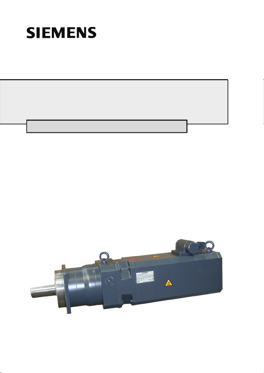
Geared motors-Planetary gear
Instructions Edition 09 / 2005
Getriebemotoren-Planetengetriebe
Motoréducteurs-Réducteur planétaire
Motorreductores-Engranaje planetario
Motoriduttori-Riduttore epicicloidale
Kuggväxelmotorer-Planetväxel
610.40 072.01

ENGLISH
CONTENTS
1 General safety instructions . . . . . . . . . . . . . . . . . . . . . . . . . . . . . . . . . . . . . . 11
2 Product information . . . . . . . . . . . . . . . . . . . . . . . . . . . . . . . . . . . . . . . . . . . . 12
2.1 Product description . . . . . . . . . . . . . . . . . . . . . . . . . . . . . . . . . . . . . . . . 12
2.1.1 General information . . . . . . . . . . . . . . . . . . . . . . . . . . . . . . . . . . . . . . . . . . . . 12
2.1.2 Gearbox . . . . . . . . . . . . . . . . . . . . . . . . . . . . . . . . . . . . . . . . . . . . . . . . . . . . .12
2.2 Scope of Delivery . . . . . . . . . . . . . . . . . . . . . . . . . . . . . . . . . . . . . . . . . 15
3 Technical specifications . . . . . . . . . . . . . . . . . . . . . . . . . . . . . . . . . . . . . . . . 16
3.1 Rating plate . . . . . . . . . . . . . . . . . . . . . . . . . . . . . . . . . . . . . . . . . . . . . . 16
3.2 Features . . . . . . . . . . . . . . . . . . . . . . . . . . . . . . . . . . . . . . . . . . . . . . . . 17
3.2.1 General information . . . . . . . . . . . . . . . . . . . . . . . . . . . . . . . . . . . . . . . . . . . . 17
3.2.2 Gearbox . . . . . . . . . . . . . . . . . . . . . . . . . . . . . . . . . . . . . . . . . . . . . . . . . . . . .17
4 Transport, Assembly . . . . . . . . . . . . . . . . . . . . . . . . . . . . . . . . . . . . . . . . . . . 19
4.1 Transport, Storage . . . . . . . . . . . . . . . . . . . . . . . . . . . . . . . . . . . . . . . . 19
4.2 Installation, Assembly . . . . . . . . . . . . . . . . . . . . . . . . . . . . . . . . . . . . . . 20
4.2.1 General information . . . . . . . . . . . . . . . . . . . . . . . . . . . . . . . . . . . . . . . . . . . . 20
5 Initial Start up . . . . . . . . . . . . . . . . . . . . . . . . . . . . . . . . . . . . . . . . . . . . . . . . . 21
5.1 Checks before starting up . . . . . . . . . . . . . . . . . . . . . . . . . . . . . . . . . . . 21
5.2 Initial Start up . . . . . . . . . . . . . . . . . . . . . . . . . . . . . . . . . . . . . . . . . . . . 21
6 Instructions in case of faults. . . . . . . . . . . . . . . . . . . . . . . . . . . . . . . . . . . . . 22
6.1 General instructions for rectifying faults . . . . . . . . . . . . . . . . . . . . . . . . 22
6.2 Spare parts . . . . . . . . . . . . . . . . . . . . . . . . . . . . . . . . . . . . . . . . . . . . . . 22
7 Inspection, Maintenance, Disposal. . . . . . . . . . . . . . . . . . . . . . . . . . . . . . . . 23
7.1 Maintenance / Repair . . . . . . . . . . . . . . . . . . . . . . . . . . . . . . . . . . . . . . 23
7.1.1 General instructions . . . . . . . . . . . . . . . . . . . . . . . . . . . . . . . . . . . . . . . . . . . . 23
7.1.2 Lubrication . . . . . . . . . . . . . . . . . . . . . . . . . . . . . . . . . . . . . . . . . . . . . . . . . . . 24
7.2 Disposal. . . . . . . . . . . . . . . . . . . . . . . . . . . . . . . . . . . . . . . . . . . . . . . . . 24
8 Other applicable documentation. . . . . . . . . . . . . . . . . . . . . . . . . . . . . . . . . . 24
2 610.40 072.01 Siemens AG

DEUTSCH
INHALT
1 Allgemeine Sicherheitshinweise . . . . . . . . . . . . . . . . . . . . . . . . . . . . . . . . . . 27
2 Angaben zum Produkt . . . . . . . . . . . . . . . . . . . . . . . . . . . . . . . . . . . . . . . . . . 28
2.1 Produktbeschreibung. . . . . . . . . . . . . . . . . . . . . . . . . . . . . . . . . . . . . . . 28
2.1.1 Allgemeines . . . . . . . . . . . . . . . . . . . . . . . . . . . . . . . . . . . . . . . . . . . . . . . . . . 28
2.1.2 Getriebe . . . . . . . . . . . . . . . . . . . . . . . . . . . . . . . . . . . . . . . . . . . . . . . . . . . . . 28
2.2 Lieferumfang . . . . . . . . . . . . . . . . . . . . . . . . . . . . . . . . . . . . . . . . . . . . . 31
3 Technische Daten . . . . . . . . . . . . . . . . . . . . . . . . . . . . . . . . . . . . . . . . . . . . . . 32
3.1 Typenschild . . . . . . . . . . . . . . . . . . . . . . . . . . . . . . . . . . . . . . . . . . . . . . 32
3.2 Merkmale. . . . . . . . . . . . . . . . . . . . . . . . . . . . . . . . . . . . . . . . . . . . . . . . 33
3.2.1 Allgemeines . . . . . . . . . . . . . . . . . . . . . . . . . . . . . . . . . . . . . . . . . . . . . . . . . . 33
3.2.2 Getriebe . . . . . . . . . . . . . . . . . . . . . . . . . . . . . . . . . . . . . . . . . . . . . . . . . . . . . 33
4 Transport, Montage. . . . . . . . . . . . . . . . . . . . . . . . . . . . . . . . . . . . . . . . . . . . . 35
4.1 Transport, Lagerung . . . . . . . . . . . . . . . . . . . . . . . . . . . . . . . . . . . . . . . 35
4.2 Aufstellung / Montage . . . . . . . . . . . . . . . . . . . . . . . . . . . . . . . . . . . . . . 36
4.2.1 Allgemeines . . . . . . . . . . . . . . . . . . . . . . . . . . . . . . . . . . . . . . . . . . . . . . . . . . 36
5 Inbetriebnahme . . . . . . . . . . . . . . . . . . . . . . . . . . . . . . . . . . . . . . . . . . . . . . . . 37
5.1 Prüfungen vor Inbetriebnahme . . . . . . . . . . . . . . . . . . . . . . . . . . . . . . . 37
5.2 Inbetriebnahme . . . . . . . . . . . . . . . . . . . . . . . . . . . . . . . . . . . . . . . . . . . 37
6 Hinweise bei Störungen . . . . . . . . . . . . . . . . . . . . . . . . . . . . . . . . . . . . . . . . . 38
6.1 Allgemeines zur Störungsbeseitigung . . . . . . . . . . . . . . . . . . . . . . . . . . 38
6.2 Ersatzteile . . . . . . . . . . . . . . . . . . . . . . . . . . . . . . . . . . . . . . . . . . . . . . . 38
7 Inspektion, Wartung, Entsorgung . . . . . . . . . . . . . . . . . . . . . . . . . . . . . . . . . 39
7.1 Wartung / Instandhaltung. . . . . . . . . . . . . . . . . . . . . . . . . . . . . . . . . . . . 39
7.1.1 Allgemeine Hinweise . . . . . . . . . . . . . . . . . . . . . . . . . . . . . . . . . . . . . . . . . . . 39
7.1.2 Schmierung . . . . . . . . . . . . . . . . . . . . . . . . . . . . . . . . . . . . . . . . . . . . . . . . . . 40
7.2 Entsorgung . . . . . . . . . . . . . . . . . . . . . . . . . . . . . . . . . . . . . . . . . . . . . . 40
8 Mitgeltende Unterlagen . . . . . . . . . . . . . . . . . . . . . . . . . . . . . . . . . . . . . . . . . 40
Siemens AG 610.40 072.01
3

FRANÇAIS
SOMMAIRE
1 Consignes générales de sécurité . . . . . . . . . . . . . . . . . . . . . . . . . . . . . . . . . 43
2 Indications relatives au produit. . . . . . . . . . . . . . . . . . . . . . . . . . . . . . . . . . . 44
2.1 Description du produit . . . . . . . . . . . . . . . . . . . . . . . . . . . . . . . . . . . . . . 44
2.1.1 Généralités . . . . . . . . . . . . . . . . . . . . . . . . . . . . . . . . . . . . . . . . . . . . . . . . . . . 44
2.1.2 Réducteur . . . . . . . . . . . . . . . . . . . . . . . . . . . . . . . . . . . . . . . . . . . . . . . . . . . . 44
2.2 Equipements fournis . . . . . . . . . . . . . . . . . . . . . . . . . . . . . . . . . . . . . . . 47
3 Caractéristiques techniques . . . . . . . . . . . . . . . . . . . . . . . . . . . . . . . . . . . . . 48
3.1 Plaque signalétique . . . . . . . . . . . . . . . . . . . . . . . . . . . . . . . . . . . . . . . . 48
3.2 Caractéristiques . . . . . . . . . . . . . . . . . . . . . . . . . . . . . . . . . . . . . . . . . . 49
3.2.1 Généralités . . . . . . . . . . . . . . . . . . . . . . . . . . . . . . . . . . . . . . . . . . . . . . . . . . . 49
3.2.2 Réducteur . . . . . . . . . . . . . . . . . . . . . . . . . . . . . . . . . . . . . . . . . . . . . . . . . . . . 49
4 Transport, montage . . . . . . . . . . . . . . . . . . . . . . . . . . . . . . . . . . . . . . . . . . . . 51
4.1 Transport, positionnement. . . . . . . . . . . . . . . . . . . . . . . . . . . . . . . . . . . 51
4.2 Installation, montage . . . . . . . . . . . . . . . . . . . . . . . . . . . . . . . . . . . . . . . 52
4.2.1 Généralités . . . . . . . . . . . . . . . . . . . . . . . . . . . . . . . . . . . . . . . . . . . . . . . . . . . 52
5 Mise en service . . . . . . . . . . . . . . . . . . . . . . . . . . . . . . . . . . . . . . . . . . . . . . . . 53
5.1 Vérifications avant la mise en service . . . . . . . . . . . . . . . . . . . . . . . . . . 53
5.2 Mise en service . . . . . . . . . . . . . . . . . . . . . . . . . . . . . . . . . . . . . . . . . . . 53
6 Remarques en cas de dérangement . . . . . . . . . . . . . . . . . . . . . . . . . . . . . . . 54
6.1 Généralités en matière de dépannage . . . . . . . . . . . . . . . . . . . . . . . . . 54
6.2 Pièces détachées . . . . . . . . . . . . . . . . . . . . . . . . . . . . . . . . . . . . . . . . . 54
7 Inspection, entretien, élimination . . . . . . . . . . . . . . . . . . . . . . . . . . . . . . . . . 55
7.1 Entretien / Maintenance . . . . . . . . . . . . . . . . . . . . . . . . . . . . . . . . . . . . 55
7.1.1 Instructions générales. . . . . . . . . . . . . . . . . . . . . . . . . . . . . . . . . . . . . . . . . . . 55
7.1.2 Lubrification. . . . . . . . . . . . . . . . . . . . . . . . . . . . . . . . . . . . . . . . . . . . . . . . . . . 56
7.2 Environnement . . . . . . . . . . . . . . . . . . . . . . . . . . . . . . . . . . . . . . . . . . . 56
8 Documents valables. . . . . . . . . . . . . . . . . . . . . . . . . . . . . . . . . . . . . . . . . . . . 56
4 610.40 072.01 Siemens AG

ESPAÑOL
ÍNDICE
1 Indicaciones generales de seguridad . . . . . . . . . . . . . . . . . . . . . . . . . . . . . . 59
2 Datos del producto . . . . . . . . . . . . . . . . . . . . . . . . . . . . . . . . . . . . . . . . . . . . . 60
2.1 Descripción del producto . . . . . . . . . . . . . . . . . . . . . . . . . . . . . . . . . . . . 60
2.1.1 Generalidades . . . . . . . . . . . . . . . . . . . . . . . . . . . . . . . . . . . . . . . . . . . . . . . . 60
2.1.2 Engranaje . . . . . . . . . . . . . . . . . . . . . . . . . . . . . . . . . . . . . . . . . . . . . . . . . . . . 60
2.2 Volumen de suministro . . . . . . . . . . . . . . . . . . . . . . . . . . . . . . . . . . . . . 63
3 Datos técnicos. . . . . . . . . . . . . . . . . . . . . . . . . . . . . . . . . . . . . . . . . . . . . . . . . 64
3.1 Placa de características. . . . . . . . . . . . . . . . . . . . . . . . . . . . . . . . . . . . . 64
3.2 Características. . . . . . . . . . . . . . . . . . . . . . . . . . . . . . . . . . . . . . . . . . . . 65
3.2.1 Generalidades . . . . . . . . . . . . . . . . . . . . . . . . . . . . . . . . . . . . . . . . . . . . . . . . 65
3.2.2 Engranaje . . . . . . . . . . . . . . . . . . . . . . . . . . . . . . . . . . . . . . . . . . . . . . . . . . . . 65
4 Transporte, montaje . . . . . . . . . . . . . . . . . . . . . . . . . . . . . . . . . . . . . . . . . . . . 67
4.1 Transporte, almacenamiento. . . . . . . . . . . . . . . . . . . . . . . . . . . . . . . . . 67
4.2 Instalación / Montaje . . . . . . . . . . . . . . . . . . . . . . . . . . . . . . . . . . . . . . . 68
4.2.1 Generalidades . . . . . . . . . . . . . . . . . . . . . . . . . . . . . . . . . . . . . . . . . . . . . . . . 68
5 Puesta en servicio. . . . . . . . . . . . . . . . . . . . . . . . . . . . . . . . . . . . . . . . . . . . . . 69
5.1 Comprobaciones antes de la puesta en servicio . . . . . . . . . . . . . . . . . . 69
5.2 Puesta en servicio . . . . . . . . . . . . . . . . . . . . . . . . . . . . . . . . . . . . . . . . . 69
6 Indicaciones en caso de avería . . . . . . . . . . . . . . . . . . . . . . . . . . . . . . . . . . . 70
6.1 Indicaciones generales para la reparación de una avería . . . . . . . . . . . 70
6.2 Piezas de recambio . . . . . . . . . . . . . . . . . . . . . . . . . . . . . . . . . . . . . . . . 70
7 Inspección, mantenimiento, eliminación de residuos. . . . . . . . . . . . . . . . . 71
7.1 Mantenimiento . . . . . . . . . . . . . . . . . . . . . . . . . . . . . . . . . . . . . . . . . . . . 71
7.1.1 Indicaciones generales. . . . . . . . . . . . . . . . . . . . . . . . . . . . . . . . . . . . . . . . . . 71
7.1.2 Lubrificación . . . . . . . . . . . . . . . . . . . . . . . . . . . . . . . . . . . . . . . . . . . . . . . . . . 72
7.2 Evacuación . . . . . . . . . . . . . . . . . . . . . . . . . . . . . . . . . . . . . . . . . . . . . . 72
8 Documentación válida . . . . . . . . . . . . . . . . . . . . . . . . . . . . . . . . . . . . . . . . . . 72
Siemens AG 610.40 072.01
5

ITALIANO
INDICE
1 Avvertenze generiche di sicurezza . . . . . . . . . . . . . . . . . . . . . . . . . . . . . . . . 75
2 Dati sul prodotto. . . . . . . . . . . . . . . . . . . . . . . . . . . . . . . . . . . . . . . . . . . . . . . 76
2.1 Descrizione del prodotto . . . . . . . . . . . . . . . . . . . . . . . . . . . . . . . . . . . . 76
2.1.1 Informazioni generali. . . . . . . . . . . . . . . . . . . . . . . . . . . . . . . . . . . . . . . . . . . . 76
2.1.2 Riduttore . . . . . . . . . . . . . . . . . . . . . . . . . . . . . . . . . . . . . . . . . . . . . . . . . . . . . 76
2.2 Fornitura . . . . . . . . . . . . . . . . . . . . . . . . . . . . . . . . . . . . . . . . . . . . . . . . 79
3 Caratteristiche tecniche. . . . . . . . . . . . . . . . . . . . . . . . . . . . . . . . . . . . . . . . . 80
3.1 Targhetta . . . . . . . . . . . . . . . . . . . . . . . . . . . . . . . . . . . . . . . . . . . . . . . . 80
3.2 Caratteristiche . . . . . . . . . . . . . . . . . . . . . . . . . . . . . . . . . . . . . . . . . . . . 81
3.2.1 Informazioni generali. . . . . . . . . . . . . . . . . . . . . . . . . . . . . . . . . . . . . . . . . . . . 81
3.2.2 Riduttore . . . . . . . . . . . . . . . . . . . . . . . . . . . . . . . . . . . . . . . . . . . . . . . . . . . . . 81
4 Trasporto, montaggio. . . . . . . . . . . . . . . . . . . . . . . . . . . . . . . . . . . . . . . . . . . 83
4.1 Trasporto, stoccaggio . . . . . . . . . . . . . . . . . . . . . . . . . . . . . . . . . . . . . . 83
4.2 Installazione / Montaggio. . . . . . . . . . . . . . . . . . . . . . . . . . . . . . . . . . . . 84
4.2.1 Informazioni generali. . . . . . . . . . . . . . . . . . . . . . . . . . . . . . . . . . . . . . . . . . . . 84
5 Messa in funzione. . . . . . . . . . . . . . . . . . . . . . . . . . . . . . . . . . . . . . . . . . . . . . 85
5.1 Verifiche prima della messa in funzione . . . . . . . . . . . . . . . . . . . . . . . . 85
5.2 Messa in funzione . . . . . . . . . . . . . . . . . . . . . . . . . . . . . . . . . . . . . . . . . 85
6 Istruzioni in caso di guasto . . . . . . . . . . . . . . . . . . . . . . . . . . . . . . . . . . . . . . 86
6.1 Informazioni generali sull’eliminazione di guasti . . . . . . . . . . . . . . . . . . 86
6.2 Pezzi di ricambio . . . . . . . . . . . . . . . . . . . . . . . . . . . . . . . . . . . . . . . . . . 86
7 Ispezione, manutenzione, smaltimento . . . . . . . . . . . . . . . . . . . . . . . . . . . . 88
7.1 Manutenzione/Messa a punto . . . . . . . . . . . . . . . . . . . . . . . . . . . . . . . . 88
7.1.1 Indicazioni generali . . . . . . . . . . . . . . . . . . . . . . . . . . . . . . . . . . . . . . . . . . . . . 88
7.1.2 Lubrificazione . . . . . . . . . . . . . . . . . . . . . . . . . . . . . . . . . . . . . . . . . . . . . . . . . 89
7.2 Smaltimento . . . . . . . . . . . . . . . . . . . . . . . . . . . . . . . . . . . . . . . . . . . . . 89
8 Ulteriori documentazioni valide . . . . . . . . . . . . . . . . . . . . . . . . . . . . . . . . . . 89
6 610.40 072.01 Siemens AG

SVENSKA
INNEHÅLL
1 Allmän säkerhetsinformation. . . . . . . . . . . . . . . . . . . . . . . . . . . . . . . . . . . . . 93
2 Uppgifter om produkten . . . . . . . . . . . . . . . . . . . . . . . . . . . . . . . . . . . . . . . . . 94
2.1 Produktbeskrivning . . . . . . . . . . . . . . . . . . . . . . . . . . . . . . . . . . . . . . . . 94
2.1.1 Allmänt . . . . . . . . . . . . . . . . . . . . . . . . . . . . . . . . . . . . . . . . . . . . . . . . . . . . . . 94
2.1.2 Växel. . . . . . . . . . . . . . . . . . . . . . . . . . . . . . . . . . . . . . . . . . . . . . . . . . . . . . . . 94
2.2 Leveransens omfattning . . . . . . . . . . . . . . . . . . . . . . . . . . . . . . . . . . . . 97
3 Tekniska data . . . . . . . . . . . . . . . . . . . . . . . . . . . . . . . . . . . . . . . . . . . . . . . . . 98
3.1 Typskylt . . . . . . . . . . . . . . . . . . . . . . . . . . . . . . . . . . . . . . . . . . . . . . . . . 98
3.2 Kännetecken . . . . . . . . . . . . . . . . . . . . . . . . . . . . . . . . . . . . . . . . . . . . . 99
3.2.1 Allmänt . . . . . . . . . . . . . . . . . . . . . . . . . . . . . . . . . . . . . . . . . . . . . . . . . . . . . . 99
3.2.2 Växel. . . . . . . . . . . . . . . . . . . . . . . . . . . . . . . . . . . . . . . . . . . . . . . . . . . . . . . . 99
4 Transport, montage . . . . . . . . . . . . . . . . . . . . . . . . . . . . . . . . . . . . . . . . . . . 101
4.1 Transport, lagring. . . . . . . . . . . . . . . . . . . . . . . . . . . . . . . . . . . . . . . . . 101
4.2 Uppställning / montering . . . . . . . . . . . . . . . . . . . . . . . . . . . . . . . . . . . 102
4.2.1 Allmänt . . . . . . . . . . . . . . . . . . . . . . . . . . . . . . . . . . . . . . . . . . . . . . . . . . . . . 102
5 Driftsättning. . . . . . . . . . . . . . . . . . . . . . . . . . . . . . . . . . . . . . . . . . . . . . . . . . 103
5.1 Kontroller innan driftsättning . . . . . . . . . . . . . . . . . . . . . . . . . . . . . . . . 103
5.2 Driftsättning . . . . . . . . . . . . . . . . . . . . . . . . . . . . . . . . . . . . . . . . . . . . . 103
6 Information vid störningar . . . . . . . . . . . . . . . . . . . . . . . . . . . . . . . . . . . . . . 104
6.1 Allmänt om åtgärdande av störningar . . . . . . . . . . . . . . . . . . . . . . . . . 104
6.2 Reservdelar . . . . . . . . . . . . . . . . . . . . . . . . . . . . . . . . . . . . . . . . . . . . . 104
7 Inspektion, underhåll, avfallshantering . . . . . . . . . . . . . . . . . . . . . . . . . . . 105
7.1 Underhåll / reparationer . . . . . . . . . . . . . . . . . . . . . . . . . . . . . . . . . . . . 105
7.1.1 Allmänna anvisningar . . . . . . . . . . . . . . . . . . . . . . . . . . . . . . . . . . . . . . . . . . 105
7.1.2 Smörjning . . . . . . . . . . . . . . . . . . . . . . . . . . . . . . . . . . . . . . . . . . . . . . . . . . . 106
7.2 Kassering. . . . . . . . . . . . . . . . . . . . . . . . . . . . . . . . . . . . . . . . . . . . . . . 106
8 Ytterligare giltiga dokument. . . . . . . . . . . . . . . . . . . . . . . . . . . . . . . . . . . . . 106
Siemens AG 610.40 072.01
7

SVENSKA
8 610.40 072.01 Siemens AG
ENGLISH
This manual contains notes which you should observe to ensure your own personal
safety, as well to protect the product and connected equipment. Notices relating to your
personal safety are highlighted by a warning triangle. Notices solely relating to material
damage do not have an accompanying triangle. They are shown as follows according to
the degree of danger involved.
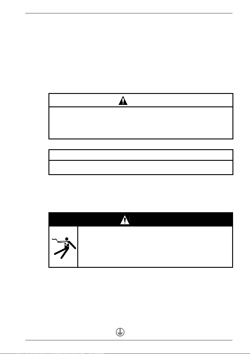
DANGER
indicates an imminently hazardous situation which, if
Pictogram
not avoided by the appropriate precautionary
measures, will result in death, serious injury or
substantial material damage.
WARNING
indicates an imminently hazardous situation which, if
Pictogram
not avoided by the appropriate precautionary
measures, could result in death, serious injury or
substantial material damage.
CAUTION
Pictogram
used with the warning triangle indicates a potentially
hazardous situation which, if not avoided, may result
in minor or moderate injury.
CAUTION
used without the warning triangle indicates a potentially hazardous
situation which, if not avoided, may result in damage to property.
NOTICE
indicates that an undesirable result or event may occur if the notice
is not observed.
Siemens AG 610.40 072.01
9

ENGLISH
Qualified Personnel
The device/system may only be set up and operated in conjunction with this manual. Only
qualified personnel should be allowed to install and work on the this equipment. Qualified
persons within the meaning of the safety instructions in this manual are persons who are
authorized to commission, ground, and mark devices, systems and circuits in accordance
with established safety practices and standards.
Intended Usage
Please note the following:
This device and its components may only be used for the applications described in the
catalogue and configuration guide, and only in conjunction with devices or components
from other manufacturers which have been approved or recommended by Siemens.
This product can only function correctly and safely if it is transported, stored, set up, and
installed correctly, and operated and maintained as recommended.
Disclaimer of Liability
We have checked the contents of this manual. Since deviations cannot be precluded
entirely, we cannot guarantee full agreement. However, the data in the manual are
reviewed regularly and any necessary corrections included in subsequent editions.
Suggestions for improvement are welcomed.
© Copyright Siemens AG 2005. All rights reserved
The reproduction, transmission or use of this document or its contents is not permitted
without express written authority. Offenders will be liable for damages.
All rights, including rights created by patent grant or registration of a utility model or
design, are reserved.
Siemens AG
Bereich Automatisierungs- und Antriebstechnik
Geschäftsgebiet Motion Control Systeme (MC)
D-97615 Bad Neustadt an der Saale, Germany
10 610.40 072.01 Siemens AG

ENGLISH
1 General safety instructions
These operating instructions contain all the necessary information concerning the
transport, installation, initial start up, maintenance etc. of geared motors.
This operating manual applies in conjunction with the SIEMENS project planning guide
and the operating manual "Three-Phase Servomotors".
The fulfillment of any rights under the warranty is conditional upon exact compliance with
the specifications and instructions in these operating instructions.
To prevent hazards of any kind arising during transport, storage, mounting, start
up, maintenance etc., the instructions relating to safety and hazards in these operating instructions and the operating instructions for three-phase servomotors
(1FK7/1FT6) must be complied with, without fail. Failure to observe the instructions can lead to serious personal injuries or property damage.
Ensure that your end product conforms to all currently valid legal requirements.
Follow the compulsory national, local and installation-specific regulations.
These motors must not be brought into use until it has been established that the
end product conforms to the currently valid directives.
Mechanical hazards, arising for example from a freely revolving transmission shaft,
must be prevented by suitable protective devices. All the keys in the shafts must be
secured.
Prevent electrical hazards from arising by precisely following the instructions in the
"Initial start up" section.
The motors’ rotors contain permanent magnets with high magnetic flux densities which
exert strong attractive forces on ferromagnetic bodies.
People fitted with a heart pacemaker are at risk in the vicinity of a disassembled
rotor. Data stored on electronic data media may be destroyed.
It is forbidden to use these servomotors in areas at risk of explosion, unless this is
expressly authorized.
The drive must be specially equipped by the manufacturer for operation outside the
permissible temperature range.
Do not touch the hot gearbox/motor casing with your bare hands. A high operating
temperature may cause burns or nervous reactions. The surface temperature of the
motors can reach > 100°C, that of the gear 90°C.
Do not touch hot surfaces!
Temperature-sensitive components (electric lines, electronic components) must not
touch hot surfaces. Overheating in the motors may destroy the windings and bearings,
and demagnetize the permanent magnets.
Only operate the motors with effective temperature control.
Intended Usage
Usage for the intended purpose includes observing all the specifications in the operating
manual and the project planning guide "Three-phase servomotors".
The gears/geared motors have been designed for the permissible outputs and loads
stated in the catalog. The geared motors may only be used for the purpose for which they
have been designed, taking all operating factors into account. Any overload of the drives
is deemed as not being use for the intended purpose. The manufacturer shall not be
liable for any damage ensuing from any unauthorized modifications to any part of the
drive.
Siemens AG 610.40 072.01
11
2 Product information
2.1 Product description
2.1.1 General information
The geared motors consist of a three-phase servomotor (1FK7/1FT6) with a flangemounted gearbox. The three-phase servomotors are supplied with mounted gearboxes.
Some models are supplied with an additional clutch.
The three-phase servomotor may be combined with all the gears /
motor adapters (clutches) described. The configuration (selection of the combination of
three-phase servomotor and gear/clutch) has to be user-related to achieve this.
Three-phase servomotors (1FK7) are permanent magnet excited, three-phase
synchronous
motors (three-phase servomotors) for operating with motor-controlled indirect a.c.
converters according to the sinusoidal current principle. The motors are intended for
driving and positioning machine tools, production machines, robots and handling
devices.
2.1.2 Gearbox
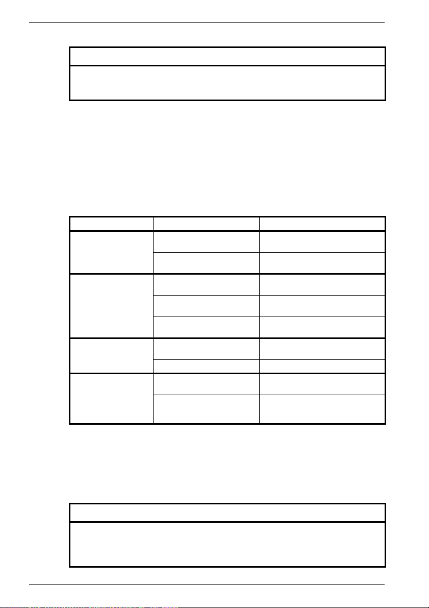
There are various models and designs of gears.
The gearing down stages reduce the usually high input speed (motor speed) to the
desired lower output speed (motor torque). This multiplies the input torque by the ratio to
the output torque, minus the reduction in the efficiency of the gear unit and with S1
operation.
Design with Types of construction Transmission shaft types
Planetary gear SP
Planetary gear LP Circle of tapped holes Solid shaft with key
Planetary gear PLE Circle of tapped holes Solid shaft with key
+
ENGLISH
Flange design Solid shaft with/without
key
NOTE
See the type plate for the particular design and mounting position.
12 610.40 072.01 Siemens AG

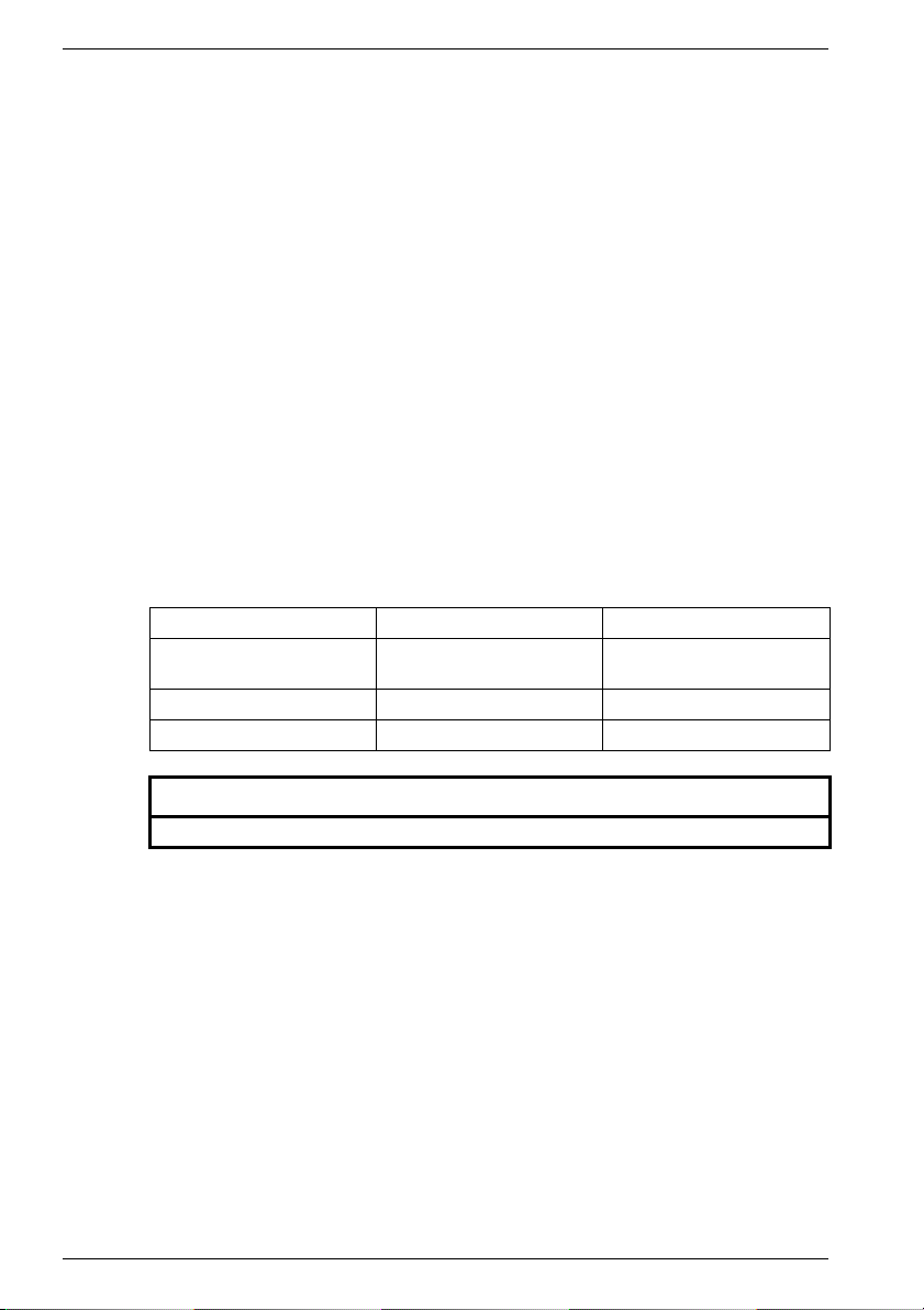
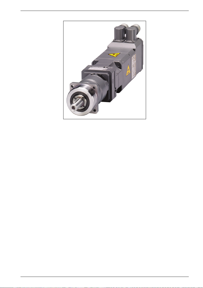
2.1.2.1 Planetary gear SP
Fig. 1 Motor with planetary gearing SP+ (example)
Motors with a planetary gear SP
planetary gear ratio. The drive and output shafts are coaxial.
The helical toothing of the planetary gear SP
minimal vibration. They have a very low circumferential backlash. The output shaft
bearings are designed so that they can absorb high external tilting moments and axial
forces.
With the exception of types SP 210 and SP 240, the gear units can be mounted in any
position without affecting the quantity of oil.
ENGLISH
+
+
have a block-type construction with a 1 or 2-stage
+
/- motors provides the quietest running and
Siemens AG 610.40 072.01
13
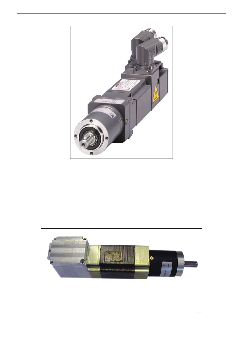
2.1.2.2 Planetary gear LP
Fig. 2 Motor with planetary gearing LP (example)
Motors with a planetary gear LP have a block-type construction with a 1 or 2-stage
planetary gear ratio.
The gear unit has integrated thermal length compensation which compensates for the
linear expansion of the motor shaft on heating. The motor is mounted and the gear unit
centered on the motor by means of the bearing-mounted clamping hub and not with the
adapter plate. This eliminates radial strain on the motor. It is adapted to various motors
by means of the adaptor plate and spacing sleeve.
2.1.2.3 Planetary gear PLE
ENGLISH
Fig. 3 Motor with planetary gearing PLE (example)
Motors with a planetary gear PLE have a block-type construction with a 1 to 3 stage
planetary gear ratio. They have been developed for applications which do not
require an
extremely low circumferential backlash.
The gear units can be mounted in any position with out affecting the quantity of grease.
14 610.40 072.01 Siemens AG

2.2 Scope of Delivery
The drive systems have been assembled individually, they have been tested and
properly packed in the works.
Upon receipt of delivery, check that the delivery is complete, check for transport damage,
and whether the scope of delivery corresponds with the consignment notes.
SIEMENS cannot accept any liability for any shortages or deficiencies reported at a later
date.
Any complaints must be reported to the transport company without delay.
Complaint instructions:
- report detectable transport damage immediately to the carrier/transport company,
- report detectable defects / incomplete delivery immediately to the responsible
SIEMENS representative.
The operating manual is part of the scope of delivery and shall therefore be kept in an
accessible place. As the delivery includes a separate type plate, the motor data must also
be kept on or near the machine or system.
ENGLISH
Siemens AG 610.40 072.01
15
3 Technical specifications
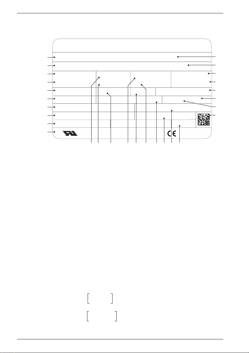
3.1 Rating plate
SIEMENS
1
3~ Motor
2
3
M
2,6
10
4
M
1,50
1N
5
Th.Cl. 155 (F)
6
Encoder A-2048
7
gear unit type: SP075S-MF1
8
ratio: I=10
9
mounting position: any
10
Fig. 4 Rating plate (example 1FT6)
1 Motor type: three-phase servomotor
2 ID No., production number
3 Zero speed continuous torque M
4 Rated torque M
5 Temperature class
6 Encoder type code
7 Gear type code
8 Gear ratio; [exact transmission ratio]
9 Identification Mounting position Geared
10 Standards and regulations
11 Zero-speed current I
12 Rated current I
13 Induced voltage U
14 Motor maximum speed n
CUS
(motor output)
(motor output)
motor
(gear drive)
1FT6041 - 4AK1 - 4EG1 - Z
T533 4392 01
I
Nm
Nm
11 12 13 15 16 17 2018 1914
[Nm]
N
[A]
N
[V]
IN
3,0AA
0
I
2,2
N
U
324 V
iN
BRAKE xxxxx xx,xx xxxxxxx
[A]
0
1max
ENGLISH
001No. YF
Made in Germany
[Nm]
0
[rpm]
Z: J09
n
n
IP
1max
1N
6000
6000
65
/min
/min
M
14,5 (S3-60%)Nm
2N
l
max
n
2
10,7
600
A
/min
RN 000 F02
oil type: xxxx xxxx xxxx
quantity of oil: x,xx l
m: kg10
EN 60034
15 Type of protection
16 Rated speed n
(gear drive)
[rpm] of the motor
1N
17 Holding brake data
18 Gear oil name ***)
19 Gearbox oil quantity ***)
20 Geared motor weight m [kg]
21 Bar code
22 Geared motor version
23 Encoder version
24 Gear drive rated torque M
(operating mode) *)
25 Drive speed n
gear drive **)
26 Maximum current I
[rpm]
2
max
[A]
2N
[Nm];
27 Order options
28 SIEMENS motor type/ designation
28
27
26
25
24
23
22
21
*)
**)
M
n
n1Nn
f M1N()=
2N
1Nn1max
1max
n
1N
---------
n
=⇒≤
2
i
n
1max
--------------
=⇒>
n
2
i
***) Only for gear unit types SP 210 and SP 240
16 610.40 072.01 Siemens AG

3.2 Features
3.2.1 General information
The technical data of the drive is stated on the rating plate.
Dimensions can be taken from the dimensional sketches in the relevant planning guide
or the DP tool "CAD-Creator".
Comply with permissible torques (max. gear housing temperature 90 °C), make a
current limitation on the servo frequency converter if necessary.
Transport temperature -20 °C to +40 °C (-4 °F to 104 °F)
Storage temperature 0 °C to +40 °C (32 °F to 104 °F)
Installation altitude ≤ up to 1000 m a.s.l,
Weight see rating plate
Degree of protection as per EN 60 034-5 IP 65 / 64
Sound level as per EN 60 034-9 aprox. 75 dB(A)
Vibration severity grade as per EN 60 034-14 Grade A
True running, coaxiality, axial run-out
deviation as per IEC 60 072-1
The dimensional sheets from the DP tool "CAD-Creator" and the "Three-Phase
Servomotors" operating instructions contain additional characteristic technical values.
3.2.2 Gearbox
3.2.2.1 Planetary gear SP
+
ENGLISH
2000 m conversion factor 0,94
2500 m conversion factor 0,9
Tolerance N
Running noises - without load
(n1= 3000 rpm; i=5) L
[dB(A)]
PA
≤ 64... ≤ 72
Max. permissible housing temperature [°C] +90
Ambient temperature [°C] 0 to +40
Lubricant *) lifetime lubricated;
Oil/grease filling capacity *)
filled and sealed in the works;
changes are not permitted
Venting
Degree of protection as per EN 60 034-5 IP 65
*) For gear unit types SP 210 and SP 240 see type plate
Siemens AG 610.40 072.01
17
3.2.2.2 Planetary gear LP
ENGLISH
Running noises (n1= 3000 rpm; i=5)
[dB(A)]
L
PA
Max. permissible housing temperature [°C] +90
Ambient temperature [°C] -10 to +40
Lubricant lifetime lubricated;
Oil/grease filling capacity
Venting
Degree of protection as per EN 60 034-5 IP 64
3.2.2.3 Planetary gear PLE
Running noises (n1= 3000 rpm; idling
speed)
[dB(A)]
L
PA
Max. permissible housing temperature [°C] +90
Ambient temperature [°C] -10 to +40
Lubricant lifetime lubricated;
Oil/grease filling capacity
Venting
Degree of protection as per EN 60 034-5 IP 64
≤ 68... ≤ 75
filled and sealed in the works;
changes are not permitted
55...70
filled and sealed in the works;
changes must be done by the manufacturer
18 610.40 072.01 Siemens AG
4 Transport, Assembly
The specifications for transport, installation and assembly in the operating
instructions for the three-phase servomotors 1FK7 (order/item no. 610.40 700.21)
and 1FT6 (order/item no. 610.43 410.21) must be complied with.
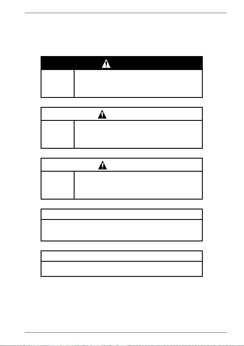
4.1 Transport, Storage
Danger during lifting and transporting procedures!
Improper handling, unsuitable or defective devices, tools etc. can
cause injuries and/or property damage.
Lifting devices, floor conveyors and lifting tackle must conform to
the currently valid regulations.
The relevant safety regulations (e.g. VBG 8) for standing under
suspended loads must be complied with during assembly work on
the holding brake or on the brake motor.
Use suitable lifting tackle for transport and assembly.
Use suspension bands and lifting eyes for transporting the geared motors.
Lifting tackle as per 98/37/EU Directive for Machines, Appendix I.
Refer to the rating plate for exact specifications of the weight of geared motors.
Observe the transport regulations applying in the country/countries concerned.
Do not strike the shafts and their bearings!
ENGLISH
CAUTION
WARNING
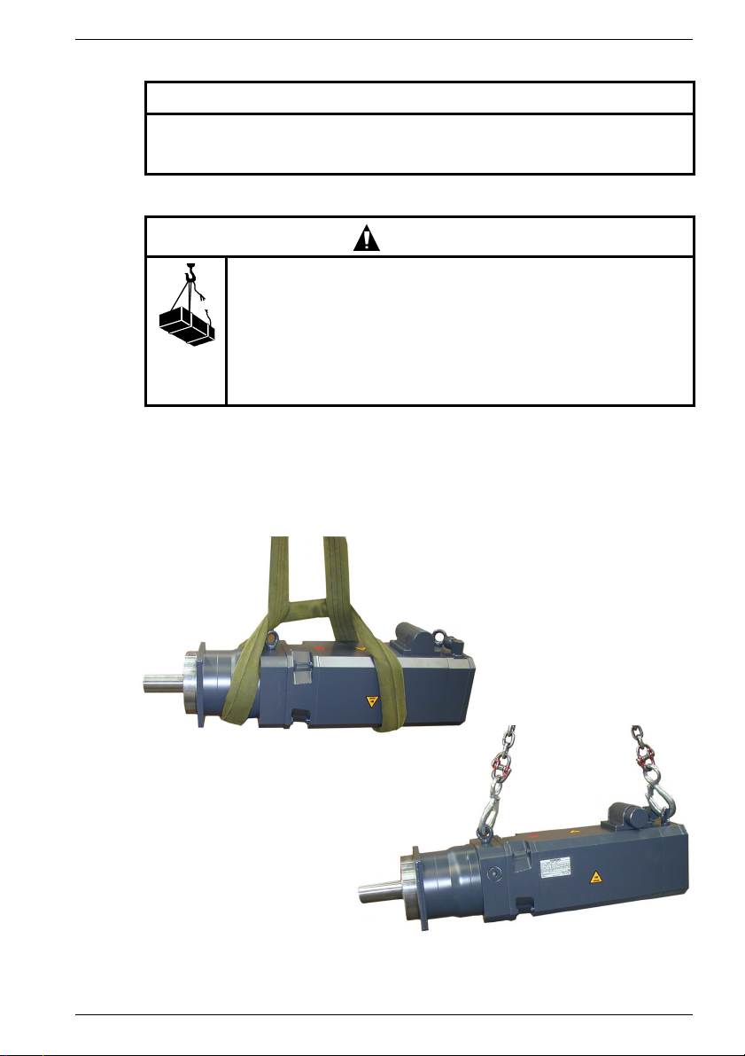
A
Fig. 5 Examples for lifting and transporting
A with suspension bands (carrying rope) B with lifting eyes/chains
Siemens AG 610.40 072.01
B
19
For transporting the unpacked drive within the works:
- lift large geared motors with lifting eyes in the ring bolts,
- lift smaller geared motors with suitable suspension bands (carrying rope) on the
geared motor.
Store in a dry, low-dust and low-vibration place (v
Transport and storage temperatures, see Chapter 3.2.1.
Condensed water in the oil chamber of the gearbox leads to rusting, which must be
avoided at all costs. Its intensity is determined by the degree of relative air humidity and
large temperature fluctuations.
It is necessary to contact SIEMENS Service if the gearbox is to be temporarily stored.
The geared motors can be stored in a horizontal position in their original packaging for a
maximum of two years in a dry environment at temperatures between 0 °C and +30 °C.
The bare parts of the gearing must be conserved.
4.2 Installation, Assembly
4.2.1 General information
Impacts on the shaft and bearings must be avoided at all costs as they damage
the bearing race. Do not exceed the permissible axial and radial forces on the
shaft end stated in the configuration specification.
The protective lacquer on the ends of the shaft and centering shoulders must be
completely removed before erection/assembly.
If solvents are used, they must not be allowed to come into contact with the lip
seals of the shaft seal rings.
ENGLISH
NOTICE
CAUTION
< 0,2 mms-1).
eff
Mounting position, mounting location
The drive may only be mounted in the ordered mounting position.
If the mounting position is changed, the internal construction of the gearbox and the
quantity of lubricant may also have to be changed. The lubrication fittings also have to
be exchanged. In such a case, it is absolutely essential to contact SIEMENS Service.
CAUTION
It must be ensured that air can circulate freely in order to prevent heat
accumulating in the entire gearbox.
Installation
The subframe for attaching the flanged gearbox must be level and torsionally rigid in
order to prevent strain on the gearbox or output shaft bearing.
The tapped center hole of the output shaft (according to DIN332 sheet 2) is provided both
for shrinking on and for axially attaching transmission elements (gear wheel, chain wheel,
belt pulley, clutch hub) by a central screw.
Shaft ends have tolerance of ISO k6. The feather key complies with DIN 6885 sheet 1.
20 610.40 072.01 Siemens AG

5 Initial Start up
The specifications for starting up / for connecting the motor in the operating
instructions for the three-phase servomotor 1FK7 (order/item no. 610.40 700.21)
and 1FT6 (order/item no. 610.43 410.21) must be complied with.
See for the lubrication instructions Chapter 7.1.2 “Lubrication”
The gear is not self-locking.
5.1 Checks before starting up
Thermal hazard from hot surfaces!
The surface temperatures of the motors may exceed 100 °C.
Do not touch hot surfaces!
Protection must be provided against accidental contact if necessary.
Temperature-sensitive components (electric lines, electronic
components) must not touch hot surfaces.
Before starting up, ensure that
- all connections have been properly made, and the plug connectors are secured
against working loose.
- all motor protection devices are active,
- the drive is not blocked,
- no other possible sources of danger are present,
- the drive is undamaged (no damage from transport/storage),
- the keys in the shaft end (if present) are secured against being thrown out,
- the direction of rotation of the drive is correct (important where there is a back-run
safety device).
ENGLISH
CAUTION
CAUTION
WARNING
Hazard from rotating rotor/freely revolving transmission shaft.
Secure output elements with suitable protective devices (protection
against accidental contact).
Secure key (if present) against being thrown out.
5.2 Initial Start up
DANGER
Electrical connections must be made by specialist personnel in accordance with
the currently valid regulations (refer to DIN VDE 0105 or IEC 364 for the
regulations concerning skilled workers).
The motor winding must be protected against thermal overload by thermal
contacts or PTC thermistor probes or similar.
The guarantee for the motor lapses if there is no motor protection.
Siemens AG 610.40 072.01
21
ENGLISH
6 Instructions in case of faults
CAUTION
The instructions for faults contained in the operating instructions for the threephase servomotor 1FK7 (order/item no. 610.40 700.21) and 1FT6 (order/item no.
610.43 410.21) must be complied with.
6.1 General instructions for rectifying faults
Refer to Table 1 first if there are deviations from normal operation or faults. Contact the
works, please also refer to the relevant section of the operating manual for the
components of the entire drive system.
Do not disable the protective devices, even in trial operation.
Consult the manufacturer or the SIEMENS service center when necessary.
- For start up, system motor converter: A&D Hotline 0180 50 50 222
- For motor / motor components: Contact in the works 0174-3110669
They will inform the customer of the nearest service partner if further action is required.
Fault Cause Remedy
Irregular running Inadequate screening of the
Vibrations Coupling elements or driven
Running noises Foreign bodies inside the
Motor overheats
(surface
temperature >140 °C)
Temperature monitoring responds
Table 1: Troubleshooting
motor or encoder cables.
Amplification of the drive controller too high
machine are badly balanced
Inadequate alignment of the
drive train
Fixing screws
are loose
motor
Bearing damage Repair by the manufacturer
Drive overloaded Check load
Heat dissipation impaired by
deposits
Check screening and grounding
Adjust controller (see converter
operating manual)
Rebalance
Realign the machine set
Check and tighten screw connections
Repair by the manufacturer
(see rating plate)
Clean surface of drives,
Ensure that the cooling air can flow
freely in and out
6.2 Spare parts
The following must be stated when ordering spare parts:
- Type designation stated on the type plate on the geared motor
- Serial number stated on the type plate on the geared motor
NOTE
The spare parts lists are not assembly instructions! They are not binding for
assembly purposes. Only original parts may be used as spare parts.
We give no warranty and accept no liability for damage resulting from any parts
not supplied by us.
22 610.40 072.01 Siemens AG
ENGLISH
7 Inspection, Maintenance, Disposal
7.1 Maintenance / Repair
7.1.1 General instructions
Clean wherever and whenever the degree of contamination makes it necessary in order
to ensure that the waste heat is adequately dissipated.
As the operating conditions vary greatly, one can only cite general intervals for fault-free
operation.
Guidelines:
- Bearing service life 20,000 hours
- Radial shaft seals aprox. 5,000 hours with oil lubrication
WARNING
The motors’ rotors contain permanent magnets with high magnetic flux densities
which exert strong attractive forces on ferromagnetic bodies.
People fitted with a heart pacemaker are at risk in the vicinity of a disassembled
rotor.
Data stored on electronic data media may be destroyed.
NOTICE
The encoder system must be readjusted each time after the motor has been
disassembled.
The maintenance of the geared motors is kept to a minimum by their design concept.
All components subject to operational wear (for example friction linings of brakes)
must be included in the regular maintenance measures. SIEMENS service partners are
available for all maintenance work on gears (see Chapter 6 “Instructions in case of
faults”).
DANGER
Electric shock hazard!
When the rotor is rotating, there is a dangerous voltage at the motor
terminals. Stop the motor before commencing any electrical work.
Only use trained, qualified personnel for assembly work on the
converters and plugs.
Observe the regulations for working in electrotechnical plants.
Safety rules for working in electrical installations as per
EN 50110-1 (DIN VDE 0105-100):
- Always work with the equipment electrically dead.
- Isolate from electrical supply.
- Secure against switching on again.
- Check electrical deadness.
- Earth and short-circuit.
- Cover or cordon off adjacent parts which are electrically live.
- Release for work.
- Connect the PE conductor to
Siemens AG 610.40 072.01
23
7.1.2 Lubrication
All gear units are filled in the works with synthetic gear oil (polyglycol) of viscosity class
ISO VG 220 or with a high performance grease.
Other lubricants and quantities of lubricant are required for other operational conditions
(see Chapter 3.2). In such cases, please contact SIEMENS
Service.
No lubricant change for these types of gear units!
The venting plug located under the adaptor plate must not be opened!
The fixing bolts of the adaptor plate must not be loosened. These bolts hold the
gear housing together.
7.2 Disposal
Motors must be disposed of in accordance with the national and local regulations by
putting them into the standard recycling process or by returning them to the
manufacturer.
The following points must be observed when disposing of the motors:
- Dispose of oil in accordance wit the old oil ordinance (for example no mixing with
solvents, cold cleansers or lacquer residues)
- Separate components for recycling into:
- electronic scrap (encoder electronics)
- scrap iron
- aluminium
- nonferrous metals (worm wheels, motor windings)
- permanent magnets
ENGLISH
NOTICE
WARNING
Danger of crushing injuries. People with heart pacemakers must keep well away
as they at risk from the effects of the permanent magnets!
8 Other applicable documentation
These operating instructions are valid in conjunction with the following documentation:
- Project planning guide1FK7/1FT6,
Ordering / Item number 6SN1197-0AD06-... / 6SN1197-0AD02-...
- Operating instructions for the three-phase servomotor 1FK7/1FT6,
Ordering / Item number 610.40 700.21 / 610.43 410.21
- Repair instructions for the three-phase servomotor 1FK7/1FT6,
Ordering / Item number 610.43 430.21 / 610.43 411.02
24 610.40 072.01 Siemens AG
DEUTSCH
Diese Betriebsanleitung enthält Hinweise, die Sie zu Ihrer persönlichen Sicherheit sowie
zur Vermeidung von Sachschäden beachten müssen. Die Hinweise zu Ihrer persönlichen
Sicherheit sind durch ein Warndreieck hervorgehoben, Hinweise zu alleinigen
Sachschäden stehen ohne Warndreieck. Je nach Gefährdungsgrad werden sie
folgendermaßen dargestellt:
GEFAHR
bedeutet, dass Tod, schwere Körperverletzung oder
Piktogramm
erheblicher Sachschaden eintreten werden, wenn die
entsprechenden Vorsichtsmaßnahmen nicht getroffen
werden.
WARNUNG
bedeutet, dass Tod, schwere Körperverletzung oder
Piktogramm
erheblicher Sachschaden eintreten können, wenn die
entsprechenden Vorsichtsmaßnahmen nicht getroffen
werden.
VORSICHT
Piktogramm
mit Warndreieck bedeutet, dass eine leichte
Körperverletzung eintreten kann, wenn die
entsprechenden Vorsichtsmaßnahmen nicht getroffen
werden.
VORSICHT
ohne Warndreieck bedeutet, dass ein Sachschaden eintreten kann,
wenn die entsprechenden Vorsichtsmaßnahmen nicht getroffen
werden.
ACHTUNG
bedeutet, dass ein unerwünschtes Ereignis oder Zustand eintreten
kann, wenn der entsprechende Hinweis nicht beachtet wird.
Siemens AG 610.40 072.01
25

DEUTSCH
Qualifiziertes Personal
Inbetriebsetzung und Betrieb des Gerätes dürfen nur von qualifiziertem Personal
vorgenommen werden. Qualifiziertes Personal im Sinne der sicherheitstechnischen
Hinweise dieser Betriebsanleitung sind Personen, die die Berechtigung haben, Geräte,
Systeme und Stromkreise gemäß den Standards der Sicherheitstechnik in Betrieb zu
nehmen, zu erden und zu kennzeichnen.
Bestimmungsgemäßer Gebrauch
Beachten Sie:
Das Gerät darf nur für die im Katalog und in der Projektierungsanleitung vorgesehenen
Einsatzfälle und nur in Verbindung mit von Siemens empfohlenen bzw. zugelassenen
Fremdgeräten und -komponenten verwendet werden.
Der einwandfreie und sichere Betrieb des Produktes setzt sachgemäßen Transport,
sachgemäße Lagerung, Aufstellung und Montage sowie sorgfältige Bedienung und
Instandsetzung voraus.
Haftungsausschluss
Wir haben den Inhalt der Druckschrift geprüft. Dennoch können Abweichungen nicht
ausgeschlossen werden, so dass wir für die vollständige Übereinstimmung keine Gewähr
übernehmen. Die Angaben in dieser Druckschrift werden regelmäßig überprüft, und
notwendige Korrekturen sind in den nachfolgenden Auflagen enthalten. Für
Verbesserungsvorschläge sind wir dankbar.
© Copyright Siemens AG 2005. All rights reserved
Weitergabe sowie Vervielfältigung dieser Unterlage, Verwertung und Mitteilung ihres
Inhalts ist nicht gestattet, soweit nicht ausdrücklich zugestanden. Zuwiderhandlungen
verpflichten zum Schadenersatz.
Alle Rechte vorbehalten, insbesondere für den Fall der Patenterteilung oder
GM-Eintragung.
Siemens AG
Bereich Automatisierungs- und Antriebstechnik
Geschäftsgebiet Motion Control Systeme (MC)
D-97615 Bad Neustadt an der Saale
26 610.40 072.01 Siemens AG

DEUTSCH
1 Allgemeine Sicherheitshinweise
Diese Betriebsanleitung enthält alle erforderlichen Informationen über Transport,
Aufstellung, Inbetriebnahme, Wartung usw. der Getriebemotoren.
Diese Betriebsanleitung gilt in Verbindung mit der SIEMENS-Projektierungsanleitung
sowie der Betriebsanleitung „Drehstrom-Servomotoren“.
Die Erfüllung eventueller Gewährleistungsansprüche setzt die genaue Einhaltung der
Angaben und Hinweise dieser Betriebsanleitung voraus.
Zur Vermeidung von Gefährdungen jeglicher Art bei Transport, Lagerung, Anbau,
Inbetriebnahme, Wartung usw. müssen die Sicherheits- und Gefahrenhinweise
dieser Betriebsanleitung sowie der Betriebsanleitung für Drehstrom-Servomotoren (1FK7./1FT6.) unbedingt eingehalten werden! Das Nichteinhalten kann schwere Körperverletzungen oder Sachschäden zur Folge haben.
Sichern Sie für Ihr Endprodukt die Einhaltung aller bestehenden Rechtsvorschriften! Beachten Sie die verbindlichen nationalen, örtlichen und anlagenspezifischen
Vorschriften!
Die Inbetriebnahme ist so lange untersagt, bis die Konformität des Endprodukts
mit den geltenden Richtlinien festgestellt ist.
Mechanische Gefährdungen, welche z.B. von einer freidrehenden Getriebewelle
ausgehen, sind durch geeignete Schutzvorrichtungen auszuschließen! Alle Passfedern
in Wellen müssen gesichert sein!
Elektrische Gefährdungen sind durch genaue Beachtung der in Kapitel
“Inbetriebnahme” gegebenen Anweisungen auszuschließen!
Die Läufer der Motoren enthalten Permanentmagnete mit hohen magnetischen
Flussdichten und starken Anziehungskräften zu ferromagnetischen Körpern.
In der Nähe eines demontierten Läufers sind Personen mit Herzschrittmacher gefährdet. Auf elektronischen Datenträgern gespeicherte Daten können zerstört werden.
Der Einsatz in explosionsgefährdeten Bereichen ist verboten, sofern nicht ausdrücklich
bestätigt.
Für den Betrieb außerhalb des zulässigen Temperaturbereiches muss der Antrieb
werkseitig dafür ausgerüstet sein.
Thermische Gefährdung durch Berühren des Getriebe-/Motorengehäuses mit bloßer
Hand! Es kann bei entsprechender Betriebstemperatur zu Verbrennungen oder zu
schreckhaften Reaktionen kommen! Die Oberflächentemperatur der Motoren kann
> 100 °C, die der Getriebe bis 90 °C betragen.
Berühren Sie nicht heiße Oberflächen!
Temperaturempfindliche Bauteile (elektrische Leitungen, elektronische Bauteile) dürfen
nicht an heißen Oberflächen anliegen. Überhitzung der Motoren kann Zerstörung der
Wicklungen und Lager und Entmagnetisierung der Permanentmagnete bewirken.
Betreiben Sie die Motoren nur mit wirksamer Temperaturkontrolle!
Bestimmungsgemäßer Gebrauch
Das Einhalten aller Vorgaben der Betriebsanleitung und der Projektierungsanleitung
„Drehstrom-Servomotoren“ ist Bestandteil der bestimmungsgemäßen Verwendung.
Die Getriebe/Getriebemotoren sind für die im Katalog angegebenen zulässigen
Leistungen und Belastungen konzipiert. Die Getriebemotoren dürfen nur für den
Einsatzfall verwendet werden, für den sie unter Berücksichtigung aller Betriebsfaktoren
projektiert wurden. Jegliche Überlastung der Antriebe gilt als nicht bestimmungsgemäße
Verwendung. Eigenmächtige Veränderungen am gesamten Antrieb schließen eine
Haftung des Herstellers für daraus entstehende Schäden aus.
Siemens AG 610.40 072.01
27
2 Angaben zum Produkt
2.1 Produktbeschreibung
2.1.1 Allgemeines
Die Getriebemotoren bestehen aus einem Drehstrom-Servomotor (1FK7./1FT6.) mit
angeflanschtem Getriebe. Die Drehstrom-Servomotoren werden mit montiertem
Getriebe ausgeliefert. Einige Ausführungen werden mit zusätzlicher Kupplung
ausgeliefert.
Es ist möglich den Drehstrom-Servomotor mit allen beschriebenen Getrieben/
Motoradaptern (Kupplungen) zu kombinieren. Dazu muss die Projektierung (Auswahl
der Kombination Drehstrom-Servomotor und Getriebe/Kupplung) anwenderbezogen
realisiert werden.
Die Drehstrom-Servomotoren (1FK7.) sind permanentmagneterregte DrehstromSynchron-Motoren (Drehstrom-Servomotoren) zum Betrieb mit motorgesteuerten
Pulswechselrichtern nach dem Sinusstromprinzip. Die Motoren sind vorgesehen für
Antrieb und Positionierung von Werkzeug- und Produktionsmaschinen sowie Robotern
und Handhabungsgeräten.
2.1.2 Getriebe
Die Getriebe kommen in verschiedenen Ausführungen und Bauformen zum Einsatz.
Die ins Langsame übersetzenden Getriebestufen reduzieren die meist hohe
Eintriebsdrehzahl (Motordrehzahl) auf die gewünschte niedrigere Abtriebsdrehzahl
(Motormoment). Das Eintriebsdrehmoment vervielfacht sich dabei, abzüglich der
Reduzierung durch den Wirkungsgrad des Getriebes und bei S1-Betrieb, um die
Übersetzung auf das Abtriebsdrehmoment.
Ausführung mit Bauformen Getriebewellenformen
+
Planetengetriebe SP
Planetengetriebe LP Gewindelochkreis Vollwelle mit Passfeder
Planetengetriebe PLE Gewindelochkreis Vollwelle mit Passfeder
Flanschausführung Vollwelle mit / ohne
DEUTSCH
Passfeder
HINWEIS
Die jeweilige Bauform bzw. Einbaulage ist dem Typenschild zu entnehmen.
28 610.40 072.01 Siemens AG
2.1.2.1 Planetengetriebe SP
Fig. 1 Motor mit Planetengetriebe SP+ (Beispiel)
Motoren mit Planetengetriebe SP
Planetenübersetzung aufgebaut. Antriebs- und Abtriebswelle liegen koaxial.
Die Planetengetriebe SP
Laufruhe und Schwingungen werden minimiert. Sie besitzen ein sehr geringes
Verdrehspiel. Die Abtriebswellenlagerung ist so ausgeführt, dass hohe externe
Kippmomente und Axialkräfte aufgenommen werden können.
Die Getriebe können, mit Ausnahme der Typen SP 210 und SP 240, in jeder beliebigen
Einbaulage bei gleichbleibender Ölmenge angebaut werden.
DEUTSCH
+
+
sind in Blockbauweise mit 1- oder 2-stufiger
+
/-motoren bieten durch die Schrägverzahnung höchste
Siemens AG 610.40 072.01
29

2.1.2.2 Planetengetriebe LP
Fig. 2 Motor mit Planetengetriebe LP (Beispiel)
Motoren mit Planetengetriebe LP sind in Blockbauweise mit 1- bis 2-stufiger
Planetenübersetzung aufgebaut.
Das Getriebe besitzt einen integrierten thermischen Längenausgleich, dieser
kompensiert die Motorwellen-Längenausdehnung bei Erwärmung. Der Motoranbau und
die Motorzentrierung des Getriebes erfolgt über die gelagerte Klemmnabe und nicht über
die Adapterplatte. Ein radiales Verspannen des Motors ist somit ausgeschlossen. Die
Anpassung an verschiedene Motoren wird mittels Adapterplatte und Distanzhülse
realisiert.
2.1.2.3 Planetengetriebe PLE
DEUTSCH
Fig. 3 Motor mit Planetengetriebe PLE (Beispiel)
Motoren mit Planetengetriebe PLE sind in Blockbauweise mit 1- bis 3-stufiger
Planetenübersetzung aufgebaut und wurde für Anwendungsfälle entwickelt, bei denen
ein extrem geringes Verdrehspiel nicht
erforderlich ist.
Die Getriebe können in jeder beliebigen Einbaulage bei gleichbleibender Fettmenge
angebaut werden.
30 610.40 072.01 Siemens AG
 Loading...