

Siemens Flender FLUDEX 4600 FAM, Flender FLUDEX 4600 FAD, Flender FLUDEX 4600, Flender FLUDEX 4600 FADB, Flender FLUDEX 4600 FADS Operating Instructions Manual
...Page 1

FLENDER COUPLINGS
- - - - - - - - - - - - - - - - - - - - - - - - - - - - - - - - - - - - - - - - - - - - - - - - - - - - - - - - - - - - - -
FLUDEX
- - - - - - - - - - - - - - - - - - - - - - - - - - - - - - - - - - - - - - - - - - - - - - - - - - - - - - - - - - - - - -
Operating instructions 4600 en
Edition 10/2017
- - - - - - - - - - - - - - - - - - - - - - - - - - - - - - - - - - - - - - - - - - - - - - - - - - - - - - - - - - - - - -
FAO, FAD, FAE, FAM, FADB, FADS, FAK, FAKB, FAR
- - - - - - - - - - - - - - - - - - - - - - - - - - - - - - - - - - - - - - - - - - - - - - - - - - - - - - - - - - - - - -
flender.com
Page 2

Page 3

T
echnical data
T
T
1
General notes
FLENDER COUPLINGS
FLUDEX
4600 en
Operating instructions
Safety instructions
ransport
and storage
echnical
description
Fitting
Start-up
Operation
Faults, causes
and remedy
2
3
4
5
6
7
8
9
FAO, FAD, FAE, FAM, FADB, FADS, FAK, FAKB,
FAR
Maintenance
and repair
Spare parts,
customer service
Declarations
10
11
12
Edition 10/2017
Page 4

Legal notes
Warning note concept
This manual comprises notes which must be observed for your personal safety and for preventing material
damage. Notes for your personal safety are marked with a warning triangle or an "Ex" symbol (when applying
Directive 2014/34/EU), those only for preventing material damage with a "STOP" sign.
WARNING! Imminent explosion!
The notes indicated by this symbol are given to prevent explosion damage.
Disregarding these notes may result in serious injury or death.
WARNING! Imminent personal injury!
The notes indicated by this symbol are given to prevent personal injury.
Disregarding these notes may result in serious injury or death.
WARNING! Imminent damage to the product!
The notes indicated by this symbol are given to prevent damage to the product.
Disregarding these notes may result in material damage.
NOTE!
The notes indicated by this symbol must be treated as general operating information.
Disregarding these notes may result in undesirable results or conditions.
WARNING! Hot surfaces!
The notes indicated by this symbol are made to prevent risk of burns due to hot surfaces
and must always be observed.
Disregarding these notes may result in light or serious injury.
Where there is more than one hazard, the warning note for whichever hazard is the most serious is always used.
If in a warning note a warning triangle is used to warn of possible personal injury, a warning of material damage
may be added to the same warning note.
Qualified personnel
The product/system to which this documentation relates may be handled only by persons qualified for the work
concerned and in accordance with the documentation relating to the work concerned, particularly the safety and
warning notes contained in those documents.
Qualified personnel must be specially trained and have the experience necessary to recognise risks associated
with these products and to avoid possible hazards.
Proper use of Flender products
Observe also the following:
Flender products must be used only for the applications provided for in the catalogue and the relevant technical
documentation. If products and components of other makes are used, they must be recommended or approved
by Flender. The faultfree, safe operation of the products calls for proper transport, proper storage, erection,
assembly, installation, startup, operation and maintenance. The permissible ambient conditions must be
adhered to. Notes in the relevant documentations must be observed.
Trade marks
All designations to which the registered industrial property mark ® is appended are registered trademarks of
Flender GmbH. Other designations used in this document may be trademarks the use of which by third parties
for their own purposes may infringe holders’ rights.
Exclusion of liability
We have checked the content of the document for compliance with the hard and software described.
Nevertheless, variances may occur, and so we can offer no warranty for complete agreement. The information
given in this document is regularly checked, and any necessary corrections are included in subsequent editions.
Explanation regarding Machinery Directive 2006/42/EC
The couplings described here are “components” in accordance with the Machinery Directive and do not require
a declaration of incorporation.
Flender GmbH
Alfred-Flender-Straße 77
46395 Bocholt
GERMANY
Document number: 4600 en
10/2017 Subject to alterations
Copyright © Flender GmbH 2017
All rights reserved
Page 5

Contents
1. Technical data 7.....................................................
1.1 General data 7.......................................................................
1.2 Coupling versions 7...................................................................
1.3 Data relating specifically to the coupling 7................................................
2. General notes 8.....................................................
2.1 Introduction 8........................................................................
2.2 Copyright 8..........................................................................
3. Safety instructions 9.................................................
3.1 Obligations of the user 9...............................................................
4. Transport and storage 10.............................................
4.1 Scope of supply 10....................................................................
4.2 Transport 10..........................................................................
4.3 Storage of the coupling 10..............................................................
4.4 Storage area for a protracted period 10...................................................
5. Technical description 11..............................................
5.1 General description Type ”FA..” 11.......................................................
5.2 Construction of couplings 11............................................................
5.3 Marking the coupling parts for explosion protection 12......................................
5.4 Conditions of use for FLUDEX couplings in potentially explosive areas 13......................
6. Fitting 13.............................................................
6.1 Instructions for applying the finished bore and fitting the axial retaining means, set screws
6.1.1 Finished bore 13.......................................................................
6.1.2 Parallel keyway 15.....................................................................
6.1.3 Axial fastening 15......................................................................
6.1.4 Set screws 16.........................................................................
6.1.5 Balancing 17..........................................................................
6.2 General information on fitting 18.........................................................
6.3 Mounting the coupling parts 18..........................................................
6.4 Alignment 19..........................................................................
6.5 Possible misalignments 20..............................................................
6.5.1 Axial misalignment 20..................................................................
6.5.2 Angular misalignment 20................................................................
6.5.3 Radial misalignment 20.................................................................
6.5.4 Permissible shaftmisalignment values for radial misalignment ΔKrperm. and
6.6 Assignment of tightening torques 21......................................................
and balancing 13......................................................................
difference in gap dimension ΔSperm. 20..................................................
7. Startup 21...........................................................
7.1 Procedure before startup 21............................................................
7.2 Fluid filling 21.........................................................................
7.2.1 Operating fluid: oil 23...................................................................
7.2.2 Operating fluid: water or water emulsion 23................................................
FLUDEX 4600 en
Operating instructions 10/2017
5
Page 6

8. Operation 24.........................................................
8.1 General operating data 24..............................................................
9. Faults, causes and remedy 24.........................................
9.1 General 24............................................................................
9.2 Possible faults 25......................................................................
9.3 Incorrect use 25.......................................................................
9.3.1 Possible faults when selecting the coupling and/or coupling size 26...........................
9.3.2 Possible faults when installing the coupling 26.............................................
9.3.3 Possible faults in maintenance 27........................................................
10. Maintenance and repair 27............................................
10.1 Changing the operating fluid 27..........................................................
10.2 Changing the shaft-sealing rings 28......................................................
10.3 Maintenance interval of the NEUPEX addon coupling 28...................................
10.4 Replacement of the flexible elements 28..................................................
10.5 Disassembling the FLUDEX coupling 29..................................................
10.5.1 Disassembling the sizes 222 to 342 29....................................................
10.5.2 Disassembling the sizes 395 to 590 30....................................................
10.6 Disassembling the FLUDEX coupling 31..................................................
10.7 Reassembling the FLUDEX coupling 31...................................................
10.8 Refitting the FLUDEX coupling 31........................................................
10.9 Filling quantities for FLUDEX ”FA..” couplings, sizes 297, 395 and 516 32......................
10.10 Filling quantities for FLUDEX ”FA..” couplings, sizes 222, 342, 450 and 590 33.................
11. Spare parts, customer service 34......................................
11.1 Spareparts and customerservice addresses 34...........................................
11.2 Spare parts list, types FAO, FAK, FAD, FAE, FAM, FADB, FADS 35...........................
11.3 Spare parts list, type FAR 36............................................................
12. Declarations 37.......................................................
12.1 EU declaration of conformity 37..........................................................
6
Operating instructions 10/2017
FLUDEX 4600 en
Page 7

1. Technical data
1.1 General data
These operating instructions apply generally to FLUDEX couplings of the ”FA..” series.
1.2 Coupling versions
FAD
FAE
FAO
FADB
FADS
FAR
FAM
Fig. 1: Coupling types
1.3 Data relating specifically to the coupling
The orderspecific data relating to a delivery are, if known in case of an order, listed on the title
orderreleated page. In this case this title page diverges from that published on the Internet. The contents
of the operating instructions are, however, in this case identical.
The order number serves as the coupling’s ident number. This number appears on the coupling in light
raised relief.
FLUDEX 4600 en
Operating instructions 10/2017
7
Page 8

2. General notes
2.1 Introduction
These instructions are an integral part of the delivery of the coupling and must be kept in its vicinity for
reference at all times.
All persons involved in the installation, operation, maintenance and repair of the
coupling must have read and understood these operating instructions and must
comply with them at all times. Flender accepts no responsibility for damage or
disruption caused by disregard of these instructions.
The "FLENDER coupling" described in these instructions has been developed for stationary use in
general engineering applications.
The coupling is designed only for the application described in section 1, "Technical data". Other operating
conditions must be contractually agreed.
The coupling has been manufactured in accordance with the state of the art and is delivered in a condition
for safe and reliable use. It complies with the requirements in Directive 2014/34/EU.
The coupling must be used and operated strictly in accordance with the conditions laid down in the contract
governing performance and supply agreed by Flender and the customer.
The coupling described in these instructions reflects the state of technical development at the time these
instructions went to print.
In the interest of technical progress we reserve the right to make changes to the individual assemblies and
accessories which we regard as necessary to preserve their essential characteristics and improve their
efficiency and safety.
2.2 Copyright
The copyright to these operating instructions is held by Flender.
These instructions must not be wholly or partly reproduced for competitive purposes, used in any
unauthorised way or made available to third parties without our agreement.
Technical enquiries should be addressed to the following factory or to one of our customer services:
Flender GmbH
Schlavenhorst 100
46395 Bocholt
Tel.: +49 (0)2871 / 92-0
Fax: +49 (0)2871 / 92-2596
8
Operating instructions 10/2017
FLUDEX 4600 en
Page 9

3. Safety instructions
Any changes on the part of the user are not permitted. This applies equally to safety
features designed to prevent accidental contact.
3.1 Obligations of the user
• The operator must ensure that all persons involved in installation, operation, maintenance and repair
have read and understood these operating instructions and comply with them at all times in order to:
─ avoid injury or damage,
─ ensure the safety and reliability of the coupling,
─ avoid disruptions and environmental damage through incorrect use.
• During transport, assembly, installation, demounting, operation and maintenance of the unit, the
relevant safety and environmental regulations must be complied with at all times.
• The housing of the FLUDEX coupling is made of aluminium (ACAlSi10Mg). Depending on the
individual case, if necessary, further requirements must be taken into account when handling
aluminium.
• The coupling may only be operated, maintained and/or repaired by persons qualified for the work
concerned (see "Qualified personnel" on page 3 of this manual).
• All work must be carried out with "great care" and with due regard to safety.
• All work on the coupling must be carried out only when it is at a standstill.
The drive unit must be secured against being switched on accidentally (e.g. by locking the key switch
or removing the fuses from the power supply). A notice should be attached to the ON switch stating
clearly that work is in progress.
• The coupling must be fitted with suitable safeguards to prevent accidental contact. This fixture must
also offer protection against spurting hot operating fluid without substantially impairing the coupling
ventilation. The fusible safety plugs and filling plugs should remain accessible.
• The use of suitable operating fluids (usually oil) is necessary for the operation of the coupling. The
instructions for use enclosed by the operating fluid manufacturer must be observed.
• The drive unit must be shut down as soon as changes to the coupling are detected during operation.
• When the coupling is installed in plant or equipment, the manufacturer of such plant or equipment must
ensure that the contents of the present operating instructions are incorporated in his own prescription,
instructions and descriptions in his operating instructions.
• All spare parts must be obtained from Flender.
FLUDEX 4600 en
Operating instructions 10/2017
9
Page 10

4. Transport and storage
Observe the instructions in section 3, "Safety instructions"!
4.1 Scope of supply
The products supplied are listed in the dispatch papers. Check on receipt to ensure that all the products
listed have actually been delivered. Parts damaged during transport or missing parts must be reported in
writing immediately.
The equipment is delivered ready for operation, depending upon an order with or without fluid filling.
Couplings filled with operating medium are marked by a label ("...L, HLP 32 DIN 51524/2, operating oil
already put in") in the vicinity of the filling hole. Delivered separately with every coupling is a fusible safety
plug (depending on design also a thermal circuit breaker) with sealing rings, a locking plate and a retaining
screw, if provided for.
The coupling in design in accordance with the Directive 2014/34/EU is provided with the
CE identification mark as described in section 5.
4.2 Transport
When transporting the unit, use only lifting and handling equipment of sufficient
loadbearing capacity.
The coupling must be transported using suitable transport equipment only.
Different forms of packaging may be used depending on the size of the coupling and method of transport.
Unless otherwise agreed, the packaging complies with the HPE Packaging Guidelines.
The symbols marked on the packing must be observed at all times. These have the following meanings:
Top Fragile Keep dry Keep cool Centre of
Fig. 2: Transport symbols
4.3 Storage of the coupling
Unless otherwise expressly agreed, the coupling is delivered in a preserved condition and can be stored
in a covered, dry place for up to 3 months. If storage is provided for a protracted period, the unit should be
treated with a longterm preservative agent on all outer surfaces with the exception of the aluminium
housing (Flender must be consulted).
+Before cleaning the coupling and applying the longterm preservative agent, any
flexible elements of the NEUPEX addon coupling must be removed. The shaft-sealing
rings must not come into contact with solvents.
Correctly stored couplings retain their properties unchanged for up to five years. Unfavourable storage
conditions and improper treatment of the flexible elements and/or seals will negatively affect their physical
properties. Such negative effects may be caused by e.g. the action of oxygen, ozone, extreme
temperatures, light, moisture, or solvents.
gravity
Use no hand
hook
Attach
here
4.4 Storage area for a protracted period
The storage area must be dry and free from dust. The couplings must not be stored with chemicals,
solvents, motor fuels, acids, etc. Furthermore, the flexible elements and seals should be protected against
light, in particular direct sunlight and bright artificial light with a high ultraviolet content.
The storage areas must not contain any ozonegenerating equipment, such as
fluorescent light sources, mercury vapour lamps, highvoltage electrical equipment.
Damp storage areas are unsuitable. Ensure that no condensation occurs. The most
favourable atmospheric humidity is below 65 %.
10
Operating instructions 10/2017
FLUDEX 4600 en
Page 11

5. Technical description
Observe the instructions in section 3, "Safety instructions"!
5.1 General description Type ”FA..”
103
102
105
106
163
FAD
7
8
FAR
153
101
12
120
7 Compensating chamber
8 Working chamber
9 NEUPEX addon coupling
12 Flexible element (NEUPEX)
101 Blade shell (outer wheel)
9
102 Cover
103 Fusible safety plug
105 Bucket wheel (inner wheel)
106 Hollow shaft
120 Vbelt pulley
153 Filling plug
163 Screw plug
Fig. 3: General description Type ”FA..”
The FLUDEX coupling is a hydrodynamic fluid coupling working on the Föttinger principle. The coupling
parts on the in and output side are not connected to one another mechanically. The torque is transmitted
by the fluid flowing in the coupling and conducted via radial blades. During continuous operation very low
rotary speed slip occurs.
FLUDEX couplings of the ”FA..” series are sutiable for both directions of rotation. They can be fitted in
a horizontal, angled or vertical position. The drive should preferably take place via the hollow shaft (106)
and the bucket wheel (105) to enable the advantages of the compensating chamber (7) and the working
chamber geometry to be utilised.
If locked or overloaded by the driven machine, the coupling heats up until the fusing temperature of the
safety fuse is reached.
When the safety fuse fuses, the operating fluid escapes and the drive motor is disconnected from the
driven machine. To prevent the operating fluid spurting out, electronically or mechanically controlled
thermal monitoring equipment (see separate operating instructions) can be used.
5.2 Construction of couplings
FLUDEX couplings are made up of a few, robust parts.
The inner rotor includes the hollow shaft (106), on which the bucket wheel (105) is mounted. The outer
housing comprises the cover (102) and the blade shell (101), which are connected via a screwed flange
connection.
The outer housing and the inner rotor are doublemounted one inside the other and sealed towards the
outside by shaft-sealing rings.
For filling the coupling, two filling plugs (153) are located in filling channels offset by 180° (to prevent
overfilling). For this a screw plug (163), offset on the periphery (by approx. 60°), to be used for ventilation
while filling, for checking the filling level and for draining off the operating fluid, is located in the coupling
flange. Opposite it is the fusible safety plug (103).
FLUDEX 4600 en
Operating instructions 10/2017
11
Page 12

In the standard design the fusing temperature of the fusible safety screw is 140 °C, and the material used
for the seals is Perbunan (for a maximum continuous operating temperature of 85 °C). As an extended
standard (for continuous operating temperatures of up to 110 °C and/or synthetic oil ), the coupling can be
fitted with seals made of Viton. In this case a fusible safety plug with a fusing temperature of 160 °C is used
in the coupling.
Couplings to be used in potentially explosive areas are designed with the fusible
safety plugs (103) permitted for the temperature class.
The fusing temperature of the fusible safety plugs is stamped on their end faces, the 140 °C plugs also
being marked red, the 160 °C plugs green.
For applications where frequent faults or locking of the drive may occur it is recommended that a thermal
monitoring system be provided. This will prevent the operating fluid from escaping and being lost and the
environment from being polluted and endangered. The transmitter (EOC system) or the thermal circuit
breaker (mechanical switching equipment) is screwed into the coupling flange in place of the screw plug
(163). The fusible safety plug (103) remains in the coupling as an emergency safety device.
A thermal circuit breaker with a fusing temperature of 110 °C can be used on a coupling with Perbunan
seals and a 140 °C fusible safety plug.
A thermal circuit breaker with a fusing temperature of 140 °C can be used on a coupling with Viton seals
and a 160 °C fusible safety plug.
A 160 °C fusible safety plug can be used with an EOC system (transmitter release temperature of 125 °C),
including with Perbunan seals.
The type FAO includes only the components of the fluid coupling (without attachment) and incorporates
a connection flange point on the output side. The types FAK/FAD/FAE/FAM are couplings with NEUPEX
addon coupling integrated on the output side for connecting two shafts. The types FAKB/FADB are
FAK/FAD couplings with a brake drum. The type FADS is a FAD coupling with brake disk. The type FAR
is a coupling with Vbelt pulley on the output side.
In the flexible NEUPEX addon coupling the Hshaped Perbunan flexible elements are delivered in a
standard Shore hardness of 80.
Coupling with worn flexible elements (12) (for wear mark ΔS
be operated in potentially explosive areas.
5.3 Marking the coupling parts for explosion protection
Couplings which are intended for use in potentially explosive areas must bear the following
marking:
Flender GmbH
46393 Bocholt - Germany
FLENDER couplings FLUDEX <year built>
Marking of the fusible safety plug:
The N-EUPEX add-on coupling must have stamped on the hub parts.
, see section 10) must not
V
II 2G c b IIB T3 -30 °C ≤ Ta ≤ +50 °C
II 2D c b T 160 °C -30 °C ≤ Ta ≤ +50 °C
I M2 c b -30 °C ≤ Ta ≤ +50 °C
12
Operating instructions 10/2017
FLUDEX 4600 en
Page 13
5.4 Conditions of use for FLUDEX couplings in potentially explosive areas
The coupling with fusible safety plug with indication
Directive 2014/34/EU:
• Equipment group II (use above ground) temperature class T3 of category 2 and 3 for areas where there
are explosible gas, vapour, mist, air mixtures as well as for areas where dust can form explosible
atmospheres.
• Equipment group I (underground applications) of the category M2
6. Fitting
Observe the instructions in section 3, "Safety instructions"!
is suited for the service conditions specified in
If it is to be used below ground in potentially explosive areas, the coupling, which is
made of aluminium, must be provided with a robust casing to preclude the risk of
ignition from e.g. friction, impact or friction sparks.
The depositing of heavy metal oxides (rust) on the coupling housing must be
precluded by the casing or other suitable precautions.
The FLUDEX coupling can be delivered with attached brake disk or Vbelt pulley.
The supplier of the subassembly is responsible for the construction of the belt drive
or brake disk in conformity to the guidelines. To be noted are, amongst other things,
hazards from electrostatic charging and hot surfaces.
The use of Vbelts in conjunction with IIC gases is not permitted.
The FLUDEX coupling is delivered exclusively with a finishbored and grooved hollow shaft (106).
At the customer’s express request Flender also delivers unbored or prebored coupling parts for the
NEUPEX addon coupling.
The necessary refinishing must be carried out in strict compliance with the following specifications and with
particular care!
Responsibility for carrying out the refinishing is borne by the customer.
Flender will accept no guarantee claims arising from unsatisfactory refinishing.
Couplings with CE marking for use in potentially explosive areas are delivered
exclusively with finishbored hubs.
6.1 Instructions for applying the finished bore and fitting the axial retaining means, set screws and balancing
6.1.1 Finished bore
• On part 1: Remove flexible elements.
• On part 5: Remove part 8.
• On part 13: Remove part 3.
• On part 32: Remove part 6.
• Remove preservative agent from coupling parts.
Observe manufacturer’s instructions for handling solvent.
FLUDEX 4600 en
Operating instructions 10/2017
13
Page 14

When machining the finished bore the parts must be carefully aligned. For the permissible radial and axial
runout errors and the permissible cylindricity tolerances, see DIN ISO 286. The parts must be fitted on the
marked faces (
).
In case of part 2/3, part 4 and part 9 great caution is necessary owing to the rotating
cams.
The maximum permissible bore diameters (see table 1) are designed for drivetype
fastenings without taper action to DIN 6885/1 and must not under any circumstances
be exceeded. The finishmachined bores must be 100 % checked with suitable
measuring equipment.
If other shafthub connections (e.g. taper or stepped bore) are to be used instead of the flanged sleeve
connections provided for, Flender must be consulted.
Drivetype fastenings with taper action are not permissible.
AIT8
A
IT6
3.2
Part 1
EIT8 FIT8
EF G
IT6 IT6 IT6 IT6
3.2
3.2 3.2
Part 2 Part 2/3
3.2 3.2 3.2
BIT8 CIT8 DIT8
B
IT6 IT6 IT6
BIT8
GIT8 HIT8
C
D
3.2
Part 4
H
14
Part 5 Part 9 Brake drum (13; 32) Brake disk (32)
Fig. 4: Finished bore
Table 1: Maximum bores of the NEUPEX addon coupling
FLUDEX N‐EUPEX Maximum bore D
Size Size Part 1
222 110 - 38 48 42 38 38 42
297 125 55 45 55 60 48 55 60
342 140 60 50 60 70 52 60 70
395 225 - 85 90 80 - 80 80
450 250 - 95 100 90 - 80 90
516 315 - 120 - 100 - 100 100
590 315 - 120 - 100 - 110 100
Part 2
Part 2/3
Part 4 Part 5 Part 9
1
Brake drum
(13; 32)
Operating instructions 10/2017
Brake disk
(32)
FLUDEX 4600 en
Page 15

For drive by means of parallel keys the following fit pairs are prescribed for the bores:
Table 2: Fit pairs
Bore D
1
Selection of fit
Shaft tolerance
to FLENDER standard
Shaft tolerance
to DIN 748/1
System standard shaft
over
mm
25 100 m6
100 n6
50 m6
50 M7
up to
mm
25 k6
50 k6
50
all h8 N7
Shaft tolerances Bore tolerances
h6
The assigned fits must be adhered to in order, on the one hand, to keep the play in the
shafthub connection as low as possible, depending on utilisation of the tolerance
zones, or, on the other, to keep the hub tension arising from the oversize within the
permissible load limit. Failure to adhere to the fits may impair the shafthub
connection.
If the tolerance values of the shafts deviate from those in table 2, Flender must be
consulted.
Failure to observe these instructions may result in breakage of the coupling.
Danger from flying fragments.
The coupling then becomes an explosion hazard.
H7
H7
K7
6.1.2 Parallel keyway
The parallel keyways must be designed in accordance with DIN 6885/1. If the keyway geometry deviates,
Flender must be consulted. Taper keys or nose keys (gib headed keys) are not permissible.
The parallel keyways must be designed to suit the available parallel keys. For parallel keyways the
tolerance zone of the hub keyway width ISO JS 9 must be adhered to.
The parallel keyway must be machined as shown in the illustration.
Part 1 Part 2 Part 5 Part 9
Fig. 5: Parallel keyway
6.1.3 Axial fastening
The hollow shaft (106) of the FLUDEX coupling is secured axially with a locking plate (140) and retaining
screw (141) (included in delivery) (for tightening torques, see table 3).
Table 3: Tightening torques of the retaining screws
Part 4 Part 13
Part 32
Retaining-screw thread M6 M8 M10 M12 M16 M20 M24 M30
Tightening torque [Nm] 10 25 49 86 160 300 500 800
A set screw or end plate must be provided to secure the NEUPEX addon coupling axially. If end plates
are used, Flender must be consulted with regard to machining the recesses in the coupling parts.
FLUDEX 4600 en
Operating instructions 10/2017
15
Page 16

6.1.4 Set screws
Hexagon socket set screws with cup points to DIN 916 must be used for set screws.
The following guidelines must be observed!
The length of the set screw must be selected so that it fills the threaded hole, but does
not project from the hub (L
= d1 x 1.2).
min.
e
1
e
2
e
3
e
4
Arrangement of
the set screw
with FAK 342 /
N-EUPEX 140
d
1
Arrangement of
d
1
d
1
d
1
the set screw
with FAK 297 /
N-EUPEX 125
Part 1 Part 1 Part 2 Part 4
e
5
d
1
d
1
e
6
d
1
e
7
e
10
Part 5 Part 9 Brake drum (13; 32) Brake disk (32)
Fig. 6: Set screws
Table 4: Setscrew assignment and tightening torques of the set screws
FLUDEX
Size
222 110 M 6 - - *9 18 25 12 25 9 4
297 125 M 8 20 - 12 20 25 12 40 12 8
342 140 M 8 - 13 15 22 30 12 40 15 8
395 225 M12 - - 35 40 50 25 60 - 25
450 250 M16 - - 40 45 55 25 85 - 70
516 315 M16 - - 50 - 65 30 85 - 70
590 315 M16 - - 50 - 65 30 85 - 70
N‐EUPEX
Size
d
e
e
e
e
e
e
1
1
2
3
4
5
6
e 7e
Tightening torque of
10
the set screw [Nm]
*)Note following position of the set screw!
The set screws must always be positioned on the keyway. An exception are the
following coupling parts:
Part 2: Size 110 : Bore D
≥ 30 mm, set screw displaced by 180° relative to the keyway.
1
Part 9: all sizes: Set screw displaced approx. 180° relative to the keyway, arranged between the cams.
16
Operating instructions 10/2017
FLUDEX 4600 en
Page 17

6.1.5 Balancing
FLUDEX couplings are delivered balanced.
Prebored NEUPEX addon couplings are delivered unbalanced. It is recommended that these parts are
balanced to suit the application after finishboring (see DIN ISO 1940 and DIN 740/2), minimum balancing
quality G16.
Balancing is normally done by drilling material away.
If onelevel balancing is required on brake disk / brake drum (13; 32), the material on the front end at the
disk’s bottom is to be removed. When twolevel balancing, the brake drum (13) should be balanced
together with part 3, and part 5 with part 8.
Since the coupling part 3, the cam part, is always in a balanced condition, the coupling part 2 can be
balanced individually or together with the fitted part 3.
Finishbored couplings and/or coupling parts are balanced according to the customer’s specifications.
With onelevel balancing, on part 1 material must be removed from between the webs,
the bottom must however not be drilled right through.
On part 4 and part 9 the material must be removed from the end face between the cams.
Sufficient space must be left between the balancing hole and the cam to avoid
weakening the cam connection.
On part 13 / 32 the brake surface must not under any circumstances be damaged.
Balancing bore
Part 9Part 5Part 4Part 2Part 1
Fig. 7: Arrangement of the balancing bore with one-level balancing
Balancing bore
Part 1
Part 9Part 5Part 4Part 2
Fig. 8: Arrangement of the balancing bore with two-level balancing
Brake drum
(13; 32)
Brake drum
(13; 32)
Brake
surface
Brake disk
(32)
Brake
surface
Brake disk
(32)
FLUDEX 4600 en
Operating instructions 10/2017
17
Page 18

6.2 General information on fitting
During fitting, the "Safety Instructions" in section 3 must be observed.
Fitting work must be done with great care by trained and qualified personnel.
As early as during the planning phase it must be ensured that sufficient space is available for installation
and subsequent care and maintenance work.
Adequate lifting equipment must be available before beginning the fitting work.
If coated couplings are used in potentially explosive areas, the requirements made of
the conductivity of the coating and the limitation on the thickness of the coat applied
must be observed in accordance with EN 134631. Where coatings have a thickness
less than 200 μm, no electrostatic charge is to be expected. Where coatings are thicker
than 200 μm, an electrostatic charge of the coupling must be avoided.
6.3 Mounting the coupling parts
Before beginning installation, the shaft ends, the brake disk, the flange surfaces, and the coupling parts
must be carefully cleaned and the shaft ends rubbed with a lubricant. Before cleaning the NEUPEX
coupling parts with solvent the flexible elements must be removed.
Observe manufacturer’s instructions for handling solvent.
The coupling components and the brake disk should be fitted with the aid of suitable
equipment to avoid possible damage to the shaft bearings through axial joining
forces.
Always use suitable lifting equipment.
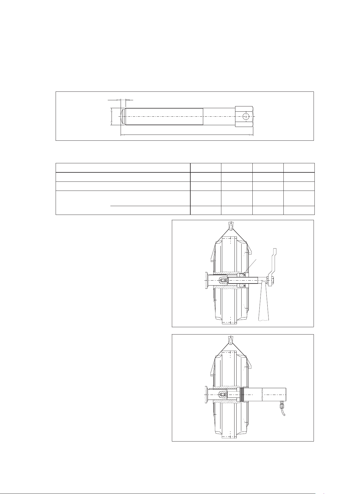
The FLUDEX coupling must be pulled on by means of a locking plate (140) and a spindle, as shown in the
figure. The coupling must be pulled on until it rests against the shaft shoulder.
Under no circumstances must fitting forces be applied through the coupling housing.
After being pulled on the FLUDEX coupling must be secured axially by means of a locking plate (140) and
a retaining screw (141) (see item 6.1.3).
Locking plate (140)
Spindle
18
Fig. 9: Mounting the coupling parts
FLUDEX 4600 en
Operating instructions 10/2017
Page 19
If necessary, heating the brake disk and the NEUPEX coupling hubs (to maximum + 150 °C) will facilitate
fitting. With temperatures over + 80 °C the flexible elements (12) must be removed from the coupling part 1
before heating. Before fitting coupling part 2 the part 3 must be fitted on the shaft.
Take precautions to avoid burns from hot parts.
The NEUPEX addon coupling must be fitted using the entire length of the bore or until it comes into
contact with the shaft shoulder. Axial securing is effected by means of the set screw or end plate.
Tightening the set screws to the tightening torque specified in item 6.1.4.
Failure to observe these instructions may result in breakage of the coupling.
Danger from flying fragments.
The coupling then becomes an explosion hazard.
Remount the removed flexible elements. It must be ensured that the flexible elements are absolutely of
identical size and have identical markings. The coupling parts must be only at a maximum temperature
of + 80 °C.
Move together the machines to be coupled.
Danger of squeezing.
Dimension "S" must be adhered to. The tightening torques of the bolted connections of part 2/3, part 10,
and part 32 are to be checked (for tightening torques and distance dimension "S", see item 6.6 and
section 1).
6.4 Alignment
FLUDEX couplings in combination with the flexible
NEUPEX addon coupling absorb positional
deviations of the shaft ends to be connected up to the
values shown in item 6.5.
When aligning, the radial and angular misalignment of
the shaft ends must be kept as small as possible,
because, other conditions being equal, this increases
the service life of the flexible elements.
The alignment must be checked once more with the
foundation bolts of the motor and gear unit/driven
machine tightened.
Any shaft misalignment through heating during
operation must be taken into account as far as
possible.
If the FLUDEX coupling is screwed to components which conduct axial forces or
bending moments into the coupling, Flender must be consulted.
S (coupling gap)
Ruler
= N‐EUPEX Size
1
d
Feeler gauge
FLUDEX 4600 en
Operating instructions 10/2017
19
Page 20

6.5 Possible misalignments
S
max
S
min
Axial misalignment Radial misalignmentAngular misalignment
Fig. 10: Possible misalignments
Misalignments of the coupling parts in relation to each other can be caused by inaccurate alignment during
assembly, but also by actual operation of the equipment (expansion due to heat, shaft deflection,
insufficiently rigid machine frames, etc.).
The following maximum permissible misalignments must by no means be exceeded
during operation.
6.5.1 Axial misalignment
Axial misalignment ΔKa (Fig. 10) of the coupling parts relative to one another is possible within the
"permissible deviation" for dimension "S" (see orderrelated title page).
6.5.2 Angular misalignment
The angular misalignment ΔKw (Fig. 10) can usefully be measured as the difference in the gap dimension
"S" (ΔS = S
max.
– S
min.
6.5.4.
If required, the permissible angular misalignment ΔKw can be calculated as follows:
S
max
ΔKa
ΔKw
ΔKr
S
min
). For the permissible values for the difference in the gap dimension, refer to item
DS
DKw
DKw
inrad +
perm.
indegrees +
perm.
perm.
d
1
180
p
DS
perm.
d
ΔS
d1 corresponds to N-EUPEX size in mm
1
see item 6.5.4.
perm.
6.5.3 Radial misalignment
For the permissible radial misalignment ΔKr
(Fig. 10) which depends upon the operating speed,
perm.
refer to item 6.5.4.
6.5.4 Permissible shaftmisalignment values for radial misalignment ΔKr
dimension ΔS
perm.
Values given in mm, rounded off
Table 5: Permissible shaftmisalignment values for radial misalignment ΔKr
difference in gap dimension ΔS
FLUDEX N‐EUPEX Coupling speed in 1/min
Size Size 250 500 750 1000 1500 2000 3000 4000 5000
222 110 0.5 0.35 0.3 0.25 0.2 0.2 0.15 0.1 0.1
297 125 0.5 0.4 0.3 0.25 0.25 0.2 0.15 0.15 0.1
342 140 0.6 0.4 0.35 0.3 0.25 0.2 0.2 0.15
395 225 0.8 0.55 0.5 0.4 0.35 0.3 0.25
450 250 0.8 0.6 0.5 0.4 0.35 0.3
516 315 1 0.7 0.6 0.5 0.4 0.35
590 315 1 0.7 0.6 0.5 0.4 0.35
perm.
and difference in gap
perm.
and
perm.
20
The numerical values of the table can be calculated as follows:
Coupling speed n in 1/min
d
corresponds to N-EUPEX size in mm
1
Radial misalignment ΔKr
DKr
perm.
+ DS
perm.
+ǒ0.1)
d
1
1000
40
Ǔ
Ǹ
n
Angular and radial misalignment may occur simultaneously.
in mm
perm.
Operating instructions 10/2017
FLUDEX 4600 en
Page 21

6.6 Assignment of tightening torques
Table 6: Assignment of tightening torques (for part number refer to section 11)
FLUDEX
Size
222 110 14 6 25 6 22 6 ‐ ‐ 18.7 6 8 10 25 7
297 125 17.5 6 25 6 60 10 75 19 / 27 / 10 18.7 6 8 10 25 7
342 140 29 8 49 8 60 10 75 19 / 27 / 10 31 8 21 13 75 10
395 225 86 10 86 10 60 10 75 19 / 27 / 10 54 10 21 13 75 10
450 250 145 14 210 14 60 10 75 19 / 27 / 10 54 10 40 17 75 10
516 315 200 14 210 14 60 10 75 19 / 27 / 10 135 14 40 17 75 10
590 315 200 14 210 14 60 10 75 19 / 27 / 10 135 14 73 19 75 10
N‐EUPEX
Size
13 22 / 23 103 110 / 142 / 163 121 130 / 131 153
TASW TASW TASW T
Nm mm Nm mm Nm mm Nm mm Nm mm Nm mm Nm mm
Tightening torques apply to bolts with untreated surfaces which are not or only lightly oiled
(coefficient of friction μ = 0.14). The use of lubricant paint or the like, which affects the
coefficient of friction "μ", is not permitted.
The tightening torques of the set screws are specified in item 6.1.4.
Tightening torque TA and wrench width SW for screws
Part number
SW TASW TASW TASW
A
7. Startup
Observe the instructions in section 3, "Safety instructions"!
7.1 Procedure before startup
Before starting up check the flexible elements for correct seating, i.e. the flexible elements must sit flush
with the end face of the hub, and the set screws for tightness, check and, if necessary, adjust the alignment
and the gap dimension "S" and check all screw connections for the specified tightening torques
(see section 1 and section 6).
7.2 Fluid filling
Only specifically permitted operating fluids may be used for operation below ground.
The behaviour and the efficiency of the FLUDEX coupling is decisively affected by the quantity of operating
fluid put in. As the filling increases, so does the transmitting capacity of the coupling, and the motor load
during starting and the maximum overload torque on the coupling rises. Operating slip decreases with the
identical load.
FLUDEX couplings must not be filled up to more than 80 to 85 % of the total volume
(limited by the overfill safety system). As a result of the higher temperaturedependent
volume expansion of the operating fluid compared with the aluminium housing higher
filling results in a sharp rise in pressure in the coupling, which can result in the
coupling being irreparably damaged before the fusing temperature of the fusible
safety plug (103) is reached.
The operating fluid must be put in at the filling plug (153). Only these filling holes are provided with a filling
channel, which offers protection against accidental overfilling. To better ventilate the inner chamber, the
screw plug (163) inserted in the outer flange, or, on the size 222, the second fusible safety plug (103),
should be unscrewed. It is set at an appropriate angle so that, in the event of imminent overfilling, the
excess can escape there.
FLUDEX 4600 en
Operating instructions 10/2017
21
Page 22

The quantity to be put into the coupling is determined in accordance with the order.
The filling quantity in litres is stamped on the coupling and specified on the
orderrelated title page.
Marking lines with litre quantities have
been cast in raised relief on the coupling
housing to assist filling the coupling and
checking the filling level.
Screw plug (163) or
Fusible safety plug (103)
Filling plug (153)
maximum filling level
When filling and/or checking the filling level
the mark with the required filling quantity
(in case of intermediate values the
corresponding intermediate position) must
be turned to the top position (12 o’clock).
In case of filling above the filling plug (153)
the coupling is filled with the required
quantity, if the filling level has reached the
lip of the hole for the screw plug (163).
Fusible safety plug (103)
After filling tighten filling plug (153) and screw plug (163) / fusible safety plug (103) (for tightening torques,
see section 6, item 6.6) and check coupling for leaktightness by carrying out a short test run. This may be
done by holding a clean piece of paper parallel to the turning axis and close to the rotating surface envelope
of the coupling. Any operating fluid spurting out will be visible on the paper.
FLUDEX couplings must not lose any operating fluid, as this loss may result in a rise
in slip and coupling temperature and ultimately to a fusing of the fusible safety
plug (103).
Then finally fit the clutch guard to prevent unintentional contact.
Faults in the drive (e.g. locking of the output side) may result in the coupling overheating. If the fusing
temperature of the fusible safety plug is reached, the insert will melt and the hot operating fluid (oil, water)
escape. The coupling protection must therefore be so designed as to also guarantee protection against
operating fluid spurting out without appreciably impairing the ventilation of the coupling. The fusible safety
plugs (103) and the filling plugs (153) should be accessible.
Rotating parts must be secured by the purchaser
against accidental contact. The coupling protection
must also protect against spurting hot operating
fluid without appreciably impairing ventilation
(see also information on the coupling).
If it is to be used below ground in potentially explosive areas, the coupling, which is
made of aluminium, must be provided with a robust casing to preclude the risk of
ignition from e.g. friction, impact or friction sparks.
The depositing of heavy metal oxides (rust) on the coupling housing must be
precluded by the casing or other suitable precautions.
Couplings to be used in potentially explosive areas are designed with the fusible
safety plugs (103) permitted for the temperature class. The coupling is marked with
the temperature class of the fusible safety plug (103).
It must be ensured that the drive shuts off not later than 5 minutes after the fusible
safety plug (103) is fused.
22
Operating instructions 10/2017
FLUDEX 4600 en
Page 23

7.2.1 Operating fluid: oil
In case of orders without performance data the filling quantity is not entered. In these cases, for operation
with oil the filling quantity for the respective coupling size can be obtained from the filling quantity tables
in section 10, item 10.9 and item 10.10 independently of the speed and output to be transmitted
(and possibly the motor output).
The filling quantity tables in section 10 apply solely to oil fillings.
HL or HLP hydraulic oils to DIN 51524 Part 1 and Part 2 of the VG 22 or VG 32 ISO viscosity classes must
be used as operating fluid.
The oil quality and purity determine the useful life of FLUDEX bearings and
shaft-sealing rings.
Table 7: Recommended oil grades
Company
Aral Degol
BG 32
Aral Vitam
GF 22
Designation
Aral Vitam
GF 32
BP Energol
HL 22 + HLP 22
BP Energol
HL 32 + HLP 32
BP Energol
HLP‐D 32
BP Bartran
32
Observe manufacturer’s instructions when handling the operating fluid.
7.2.2 Operating fluid: water or water emulsion
The coupling must be protected against freezing during standstill.
Observe manufacturer’s instructions when handling the operating fluid.
Not every FLUDEX coupling is suitable for use with water or water emulsion as an
operating fluid.
FLUDEX couplings designed for water fillings are marked as follows in the area of the
filling plug (153):
" W ".
Hyspin
DSP22 + DSP32
Tribol 943
AW22 + AW32
TORQUE
FLUID N 45
TERESSO 32 Mobil DTE 24
NUTO H 22
NUTO H 32 Mobilfluid 125
Mobil DTE 22
Mobil Vactra
Oil Light
Shell Tegula
Öl 32
Shell Tellus
Öl 22
Shell Tellus
Öl C22
TEXACO
Rando‐
Oil 32
Torque‐
Fluid 32
If water or water emulsion is used as operating fluid, only fusible safety plugs with
a maximum fusing temperature of 110 °C are permitted. At a higher fusing temperature
excessive strain is put on the coupling housing by the operating fluid vapour pressure.
FLUDEX 4600 en
Operating instructions 10/2017
23
Page 24

8. Operation
Observe the instructions in section 3, "Safety instructions"!
8.1 General operating data
During operation of the coupling watch for:
─ Changes in running noise
─ Sudden vibrations
If any irregularities are noticed during operation, switch the drive assembly off at once.
Determine the cause of the fault, using the table in section 9.
The troubleshooting table contains a list of possible faults, their causes and
suggested remedies.
If the cause cannot be identified or the unit repaired with the facilities available, you
are advised to contact one of the Flender customerservice offices for specialist
assistance (see section 2).
9. Faults, causes and remedy
Observe the instructions in section 3, "Safety instructions"!
9.1 General
The following irregularities can serve as a guide for fault tracing.
Where the system is a complex one, all the other component units must be included when tracing faults.
The coupling must run with little noise and without vibration in all operating phases. Irregular behaviour
must be treated as a fault requiring immediate remedy.
Flender will not be bound by the terms of the guarantee or warranty or otherwise be
responsible in cases of improper use of the coupling, modifications on the coupling
carried out without the agreement of Flender, or use of spare parts not supplied by
Flender.
When remedying faults and malfunctions, the coupling must always be taken out of
service.
Secure the drive unit to prevent it from being started up unintentionally.
Attach a warning notice to the start switch.
24
Operating instructions 10/2017
FLUDEX 4600 en
Page 25

9.2 Possible faults
Table 8: Possible faults
Faults
Sudden changes in the noise
level and/or sudden vibrations.
No torque transmission. The fusible safety plugs have
Possible causes Remedy
Change in alignment.
Flexible elements (12) worn.
fused through overheating or
locking and the fluid is escaping
from the coupling.
Stop the installation.
Rectify any cause of the changes in
alignment (e.g. by fastening loose
foundation bolts).
Check and, if necessary, adjust the
alignment; refer to section 6.
Check wear, procedure as described
in section 10.
Stop the installation.
Demount coupling and remove remains
of flexible elements (12).
Check and replace damaged coupling
parts.
Flexible elements (12) must be
replaced in sets.
Only use similar NEUPEX flexible
elements (12).
Fitting of coupling according to section
6 and section 7.
Stop the installation.
Rectify the cause of the overheating or
locking.
9.3 Incorrect use
Experience has shown that the following faults can result in incorrect use of the FLUDEX coupling. In
addition to observing the other instructions in this manual, care must therefore be taken to avoid these
faults. Directive 2014/34/EU requires the manufacturer and user to exercise especial care.
Fit new fusible safety plugs with new
sealing rings
Refill the coupling as described in
section 7.
If the torque is being transmitted with worn NEUPEX flexible elements (12) and metal
parts are consequently in contact, proper operation within the meaning of the
explosion protection requirements or Directive 2014/34/EU can no longer be
guaranteed.
Measurement and assessment of the wear condition of the NEUPEX flexible
elements (12) in accordance with section 10.
Failure to observe these instructions may result in breakage of the coupling.
Danger from flying fragments.
Through incorrect use the coupling may become an explosion hazard.
Incorrect use of the FLUDEX coupling can result in damage to the coupling. Coupling
damage may result in stoppage of the drive and the entire system.
FLUDEX 4600 en
Operating instructions 10/2017
25
Page 26

9.3.1 Possible faults when selecting the coupling and/or coupling size
• Important information for describing the drive and the environment are not communicated.
• System power too high.
• System speed too high or too low.
• Starting frequency too high.
• The ventilation of the coupling is inadequate.
• Chemically aggressive environment not taken into consideration.
• The ambient temperature is not permissible. (See also section 5.)
• Machining of a finished bore with incorrect diameter and/or incorrect fit assignment (see section 6 and
orderreleated title page).
• The transmission capacity of the shafthub connection is not appropriate to the operating conditions.
9.3.2 Possible faults when installing the coupling
• Components with transport or other damage are being fitted.
• When fitting coupling parts in a heated condition, already fitted NEUPEX flexible elements (12) are
being excessively heated.
• The shaft diameter is beyond the specified tolerance range.
• Coupling sides are being interchanged, i.e. their assignment to the specified drive direction is incorrect.
• Specified axial fixtures are not fitted.
• Specified tightening torques are not being adhered to.
• Alignment / shaftmisalignment values do not match the operating instructions.
• An incorrect operating fluid and/or an incorrect quantity of operating fluid is being put in.
• The coupled machines are not correctly fastened to the foundation, and as a result shifting of the
machines e.g. through loosening of the foundationscrew connection is causing excessive
displacement of the coupling parts.
• NEUPEX flexible elements (12) are being omitted or incorrectly positioned.
• The coupling protection does not comply with the guidelines to be applied. It considerably restricts
ventilation of the coupling.
• Operating conditions are being changed without authorisation.
• Components are being fitted to the coupling which transmit excessive axial forces or bending moments
to the coupling.
• Addon parts such as belt drives or brake disks are not designed in compliance with the
Directive 2014/34/EU and are an explosion hazard.
26
Operating instructions 10/2017
FLUDEX 4600 en
Page 27
9.3.3 Possible faults in maintenance
• Maintenance intervals are not being adhered to.
• An incorrect operating fluid and/or an incorrect quantity of operating fluid is being put in.
• No genuine Flender spare parts are being used.
• Specified tightening torques are not being adhered to.
• Old or damaged NEUPEX flexible elements (12) are being used.
• Fusible safety plugs (163) with an unsuitable fusing temperature are being used.
• Leakage in the vicinity of the coupling is not being identified and as a result chemically aggressive
media are damaging the coupling.
10. Maintenance and repair
Observe the instructions in section 3, "Safety instructions"!
All work on the coupling must be carried out only when it is at a standstill.
The drive unit must be secured against being switched on accidentally (e.g. by locking
the key switch or removing the fuses from the power supply). A notice should be
attached to the ON switch stating clearly that work is in progress.
Risk of burns after switching off.
Allow the FLUDEX coupling to cool down sufficiently before beginning work.
10.1 Changing the operating fluid
Never change the operating fluid immediately after operation.
There is a risk of scalding.
Allow the coupling and the operating fluid to cool down.
The operating fluid must be changed in accordance with the specifications in table 9.
When changing the operating fluid, care must be taken that the old operating fluid is completely drained
off. This can be done on size 222 through the holes in the fusible safety plugs (103) and on sizes 297 to 590
through the holes in the screw plugs (163).
Observe the environmental requirements in force.
Table 9: Operating temperatures, operating hours and years of use
Operating temperature /
Special measures
maximum 80 °C 10 000 5
maximum 95 °C
or frequent temperature peaks exceeding 100 °C:
use of Viton seals necessary
above 95 °C
only suitable synthetic oils permitted
use of Viton seals necessary
Maximum
operating hours
5000 2
According to the
specifications of the
operating-fluid
manufacturer
maximum
years of use
According to the
specifications of the
operating-fluid
manufacturer
Different operating conditions and changing frequencies are permitted with the agreement of the operating
fluid manufacturer.
FLUDEX 4600 en
Operating instructions 10/2017
27
Page 28

10.2 Changing the shaft-sealing rings
shaft-sealing rings are wearing parts subjected to relatively low stresses in the coupling. On couplings
which are filled with oil no maintenance interval need be adhered to.
On couplings which are filled with water the shaft-sealing rings of the inner seal must be replaced after
12 000 operating hours or after 2 years of operation. We recommend also replacing the other seals and
rolling bearings at the same time.
10.3 Maintenance interval of the NEUPEX addon coupling
The torsional backlash between the two coupling parts must be checked after three
months, then at least once a year.
If an increased coupling backlash does not impair the operation of the coupling, the flexible elements (12)
can continue to be used up to a specified wear limit before being replaced. To assess wear, the permitted
torsional backlash, converted to the chord dimension ΔS
table 10. To obtain the dimension ΔS
, one coupling part is rotated without torque as far as the stop and
V
a mark applied to both side (see figure 11). If the coupling part is rotated in the opposite direction of rotation
as far as the stop, the marks move apart. The distance between the marks is the chord dimension ΔS
If the dimension ΔS
exceeds the value in table 10, the flexible elements (12) must be replaced.
V
The flexible elements must be replaced in sets.
Only identically marked flexible elements must be used.
on the outer coupling diameter, is shown in
V
.
V
a
Fig. 11: Maintenance interval of the NEUPEX addon coupling
Table 10: Wear mark
FLUDEX Size 222 297 342 395 450 516 590
N-EUPEX Size [d1] 110 125 140 225 250 315 315
Wear mark ΔSV[mm] 7.0 8.0 8.0 9.0 10.0 10.5 10.5
Replacement space a [mm] 13 11 16 9 11 - -
If the above specified maintenance instructions are not adhered to, a correct operation
within the meaning of the explosionprevention requirements or Directive 2014/34/EU
can no longer be guaranteed.
Use in potentially explosive areas is then not permitted.
10.4 Replacement of the flexible elements
Only original NEUPEX flexible elements must be used for replacement to guarantee troublefree torque
transmission and faultfree operation.
1
d
V
ΔS
28
On the FAD design replacement of the flexible elements (12) is possible without moving the coupled
machines, if the replacement dimension "a" (see table 10 and figure 11) is allowed for. After the screw
connection part 2/3 is released, part 3 is shifted axially and turned towards part 2. The flexible
elements (12) are now freely accessible.
On the FADS design the flexible elements (12) can be demounted after the adaptor (6) and the cam part (7)
has been removed.
For refitting, the instructions in section 6, "Fitting", and section 7, "Startup", must be carefully observed.
FLUDEX 4600 en
Operating instructions 10/2017
Page 29
10.5 Disassembling the FLUDEX coupling
For part designations, see section 11.
Risk of burns after switching off.
Allow the FLUDEX coupling to cool down sufficiently before beginning work.
10.5.1 Disassembling the sizes 222 to 342
After moving the motor away the retaining screw (141) and locking plate (140) are first removed and then
the locking ring (124) demounted. When pulling off the FLUDEX coupling, care must be taken that
pullingoff forces are conducted only through the steel hollow shaft (106).
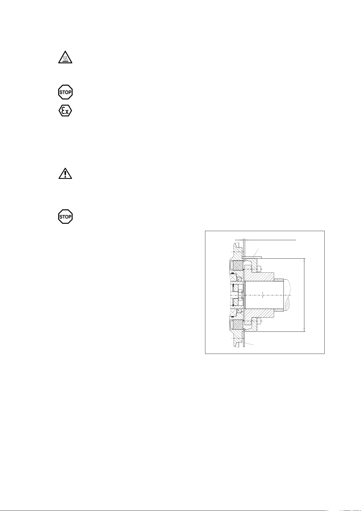
The coupling is best pulled off with the aid of a special detaching device as shown in figure 12. The spindle
with the pullingoff nut is inserted so that the collar (D) of the pullingoff nut is located behind the recess
for the locking ring (124) (Fig. 13). To prevent the spindle seizing, the pressure surface and the thread must
be treated with a lubricant (e.g. Molykote).
Nut
D
L
Spindle
G
Fig. 12: Disassembling the sizes 222 to 342 -a
Table 11: Dimensions of the threaded spindle and pullingoff nut, sizes 222 to 342
Size 222 297 342
Spindle thread G G 1/4 G 1/2 G 3/4
Nut collar Dh8 [mm] 30 45 55
Spindle length L
[mm]
FAO, FAK, FAKB, FAD, FADB, FAE, FAM, FADS 200 305 280
FAR 200 305 420
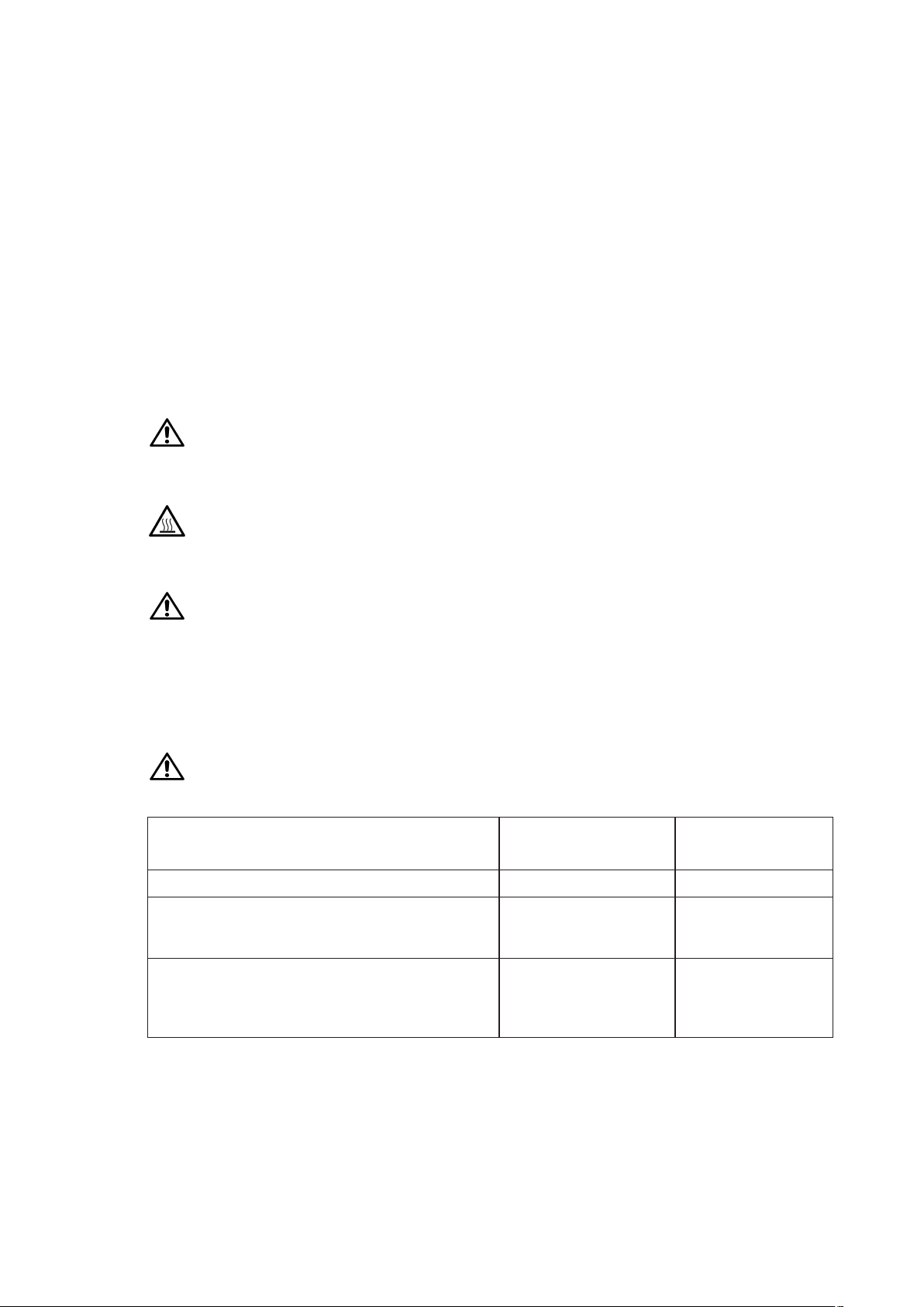
The locking ring (124) is refitted and the spindle turned forward as far as the shaft stub end face and into
the safety countersink in the centring thread. Care must be taken that the nut collar rests evenly against
the locking ring.
To prevent flexing and canting, the spindle should be supported as shown.
Fig. 13: Disassembling the sizes 222 to 342 -b
The coupling is pulled off the shaft stub by turning the spindle further into the forcingoff thread and bracing
the nut. It is recommended that a hydraulic spindle be used, depending on the size of the coupling.
FLUDEX 4600 en
Operating instructions 10/2017
124
2
1
124
3
29
Page 30
10.5.2 Disassembling the sizes 395 to 590
After moving the motor away the retaining screw (141) and locking plate (140) are first removed. When
pulling off the FLUDEX coupling, care must be taken that pullingoff forces are conducted only through the
steel hollow shaft (106).
The coupling is normally pulled off with the aid of a threaded spindle, as shown in figure 14 a. The spindle
is screwed into the forcingoff thread (dimension G) of the sleeve (143) and turned forward as far as the
shaft stub end face and into the protective countersink in the centring thread (Figure 14 b). To prevent the
spindle seizing, the pressure surface and the thread must be treated with a lubricant (e.g. Molykote).
10
G
L
Fig. 14 a
Fig. 14: Disassembling the sizes 395 to 590 -a
Table 12: Dimensions of the threaded spindle and external cylinder threads, sizes 395 to 590
Size 395 450 516 590
Spindle thread G G 1 G 1 G 1 1/2 G 1 1/2
External cylinder thread K M68 x 2 M68 x 2 M100 x 2 M100 x 2
Spindle length L
[mm]
FAO, FAK, FAKB, FAD, FADB,
FAE, FAM, FADS
FAR 420 590 590 720
280 410 410 410
To prevent flexing and canting, the spindle
should be supported as shown.
The coupling is pulled off the shaft stub by
turning the spindle further into the forcingoff
thread and bracing the nut. The shaft stub
must be fastened to prevent it from rotating.
143
30
Depending on the size of the coupling, it is
recommended that a hydraulic spindle or
a hydraulic cylinder be used, as described in
the following.
After demounting the threaded bush (143)
a hydraulic cylinder with a matching external
cylinder thread "K" (see table 12) can be
screwed into the free mounting thread of the
hollow shaft (106) (figure 14 c).
The coupling can then be pulled off the shaft
stub by operating the hydraulic cylinder.
Fig. 14 b
K
Fig. 14 c
FLUDEX 4600 en
Operating instructions 10/2017
Page 31
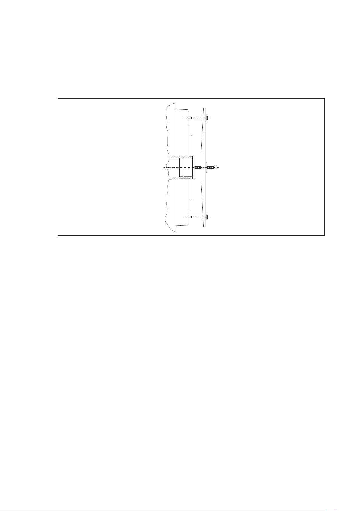
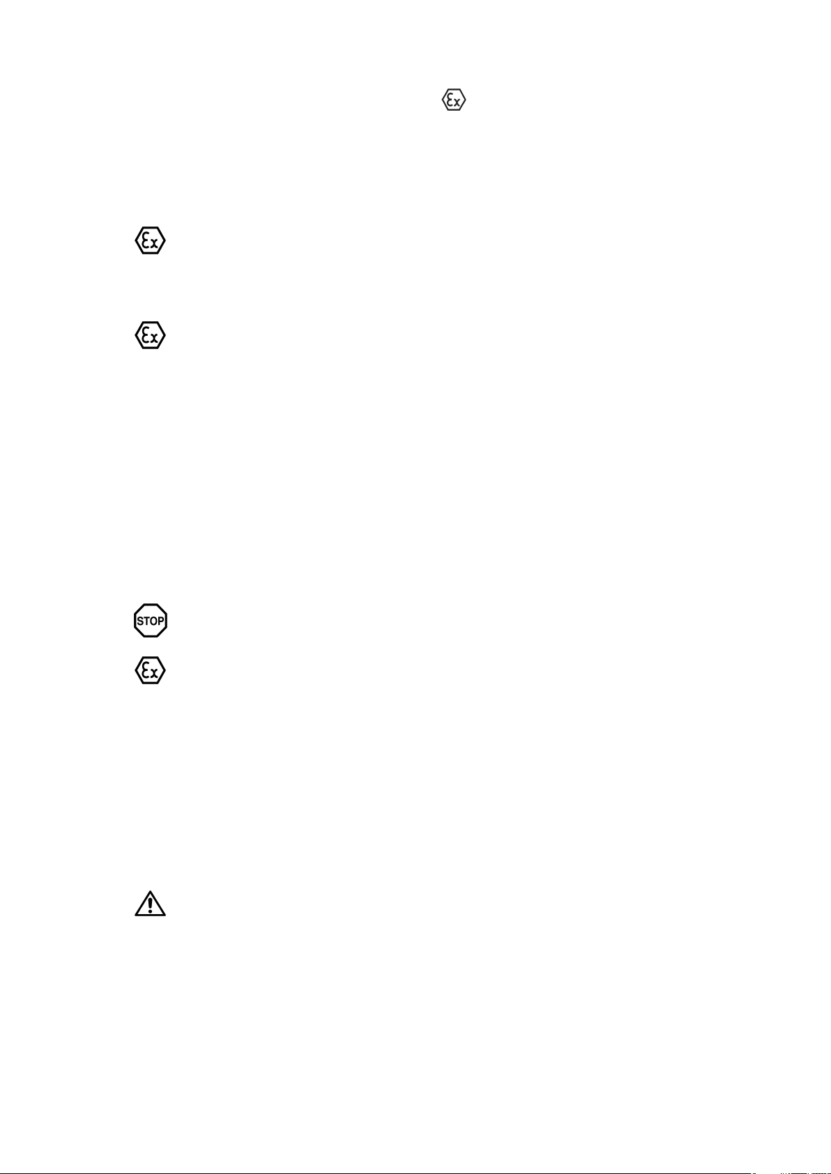
10.6 Disassembling the FLUDEX coupling
For part designations, see section 11.
FLUDEX couplings should as far as possible be repaired at the manufacturer’s works.
Before disassembly the housing parts must be marked on the flange in their positions relative to one
another.
The housing parts of the coupling, the shell (101) and the cover (102) are joined at the outer flange by
screws (130) and nuts (131). For disassembly these screws must first be removed.
Fig. 15: Disassembling the FLUDEX coupling
To pull off the shell and cover, a pressure spindle with a bridge and pulling screws must be applied as
shown in figure 15. The pressure acts on the end face of the steel hollow shaft. The pulling screws are
inserted in the flange threads of the shell or cover. After the shell and cover are pulled off, the internal parts
(rolling bearings, shaft-sealing rings, etc.) will be accessible. The sealing elements should be replaced
every time the coupling is disassembled.
10.7 Reassembling the FLUDEX coupling
Reassembly is carried out in the reverse order (note part marking). The Oring (114) must be lightly
greased to assist assembly. The shaftsealing rings (111; 132) are fitted with a grease filling between the
dust and sealing lips. Likewise, on the design with an additional Fey laminar ring seal the space between
the shaftsealing ring and the plates and the platemounting groove in the shaft must be filled with grease.
After the old sealing thread has been removed and the sealing surfaces have been cleaned, a fresh sealing
thread must be applied to places on the flange which have been sealed with sealing thread. The sealing
thread must be placed in a circular form at the place provided on the sealing surface and with the thread
ends crossed over. The sealing surface must be undamaged and may be lightly greased for better
positioning of the sealing thread.
For tightening torques for screw connections, see section 6, item 6.6.
10.8 Refitting the FLUDEX coupling
For refitting, the instructions in section 6, "Fitting", and section 7, "Startup", must be carefully observed.
FLUDEX 4600 en
Operating instructions 10/2017
31
Page 32

10.9 Filling quantities for FLUDEX ”FA..” couplings, sizes 297, 395 and 516
Guide values for VG 22/VG 32 mineral oil
With drive via hollow shaft (106) (inner wheel), valid for T
max.
= 2.0 x T
nom.
Table 13: Filling quantities for FLUDEX ”FA..” couplings, sizes 297, 395 and 516
Speed 1/min
Output
600 740 890 980 1180 1470 1770 2300 2950 3550
kW Oil-filling quantities in litres
0.55 3.2 2.8
0.75 3.5 3.0 2.6
1.1 3.9 3.3 2.9 2.7
2.2 7.3 4.0 3.4 3.2 2.8
3.0 7.9 6.8 3.7 3.4 3.0 2.5
4.0 8.5 7.3 4.0 3.7 3.2 2.7
5.5 9.4 7.9 6.8 4.1 3.5 2.9 2.6
7.5 17.0 8.5 7.4 6.9 3.8 3.2 2.8 2.4
11 18.7 16.0 8.1 7.6 6.6 3.5 3.0 2.5
15 20.3 17.3 8.9 8.2 7.1 3.8 3.3 2.7
18 21.4 18.0
15.7 8.6 7.4 4.0 3.4 2.8 2.4
22 19.0 16.5 15.4 7.8 6.6 3.6 3.0 2.5
30 20.6 17.8 16.6 8.5 7.2 6.3 3.2 2.7 2.4
37 18.8 17.5 15.2 7.6 6.6 3.4 2.8 2.5
45 19.8 18.4 16.0 7.9 6.9 3.6 2.9 2.6
55 21.0 19.3 16.8 8.4 7.3
6.0 3.1 2.7
75 21.1 18.1 15.4 7.9 6.5 5.3 2.9
90 19.0 16.1 14.1 6.7 5.6 3.0
110 20.1 16.9 14.8 7.1 5.9
132 17.7 15.4 7.9 6.2
160 18.6 16.2 13.4 6.5
180 19.2 16.7 13.8 7.0
200 17.1 14.1
225 17.6 14.6
250 18.1 14.9
280
15.3
315 15.8
350 17.1
With different operating fluids, drive via the housing or T
not equal to 2 x T
max.
observe changed filling quantities.
Size 297
Size 395
Size 516
nom.
32
Operating instructions 10/2017
FLUDEX 4600 en
Page 33

10.10 Filling quantities for FLUDEX ”FA..” couplings, sizes 222, 342, 450 and 590
Guide values for VG 22/VG 32 mineral oil
With drive via hollow shaft (106) (inner wheel), valid for T
max.
= 2.0 x T
nom.
Table 14: Filling quantities for FLUDEX ”FA..” couplings, sizes 222, 342, 450 and 590
Speed 1/min
Output
600 740 890 980 1180 1470 1770 2300 2950 3550
kW Oil-filling quantities in litres
0.55 4.3 1.5 1.4 1.3 1.1
0.75 4.7 1.65 1.5 1.4 1.2
1.1 5.1
4.4 1.65 1.6 1.4 1.1
2.2 6.2 5.2 4.5 4.2 1.6 1.4 1.2
3.0 9.5 5.6 4.9 4.6 1.65 1.5 1.3 1.0
4.0 10.2 6.1 5.3 4.9 4.3 1.6 1.4 1.1
5.5 11.0 9.4 5.7 5.3 4.6 1.65 1.5 1.2 1.0
7.5 12.0 10.2 6.2 5.8 5.0 4.3 1.6 1.3 1.1
11 13.4 11.2 9.7 6.4 5.5 4.7 4.1 1.5 1.2 1.0
15 24.8 12.2 10.5 9.8 6.0 5.0 4.4 1.6 1.3 1.1
18 25.9 12.9 11.0 10.3 6.3 5.3 4.6 3.9 1.4 1.2
22 27.3 23.3 11.6 10.8 9.4 5.5 4.8 4.0 1.4 1.25
Size 222
30 29.7 25.2 12.7 11.7 10.1 6.0 5.2 4.3 3.7 1.4
37 31.5 26.5 23.1 12.4 10.7 9.1 5.5 4.5 3.9 1.5
45 27.9 24.2 22.6 11.2 9.5 5.8 4.7 4.0 3.5
55 29.5 25.5 23.7 11.9 10.0 8.8 5.0 4.2 3.7
75 27.6 25.7 22.3 10.8 9.4 5.4 4.5 3.9
90 29.0 26.9 23.4 11.3 9.8 8.1 4.7 4.1
110 28.3 24.5 12.0 10.4 8.6 4.9 4.3
132 29.7 25.7 21.9 10.8 8.9 7.6 4.5
160 27.0 22.9 20.0 9.3 7.8
180 27.8 23.5 20.6 10.0 8.0
200 28.6 24.2 21.2 10.9 8.2
225
24.9 21.8 11.5 8.5
250 25.6 22.3 9.6
280 26.3 22.9 9.9
315 27.1 23.6 10.5
350 24.2
400 26.4
Size 342
Size 450
Size 590
With different operating fluids, drive via the housing or T
observe changed filling quantities.
FLUDEX 4600 en
Operating instructions 10/2017
not equal to 2 x T
max.
nom.
33
Page 34

11. Spare parts, customer service
By stocking the most important spare and wearing parts on site you can ensure that the coupling is ready
for use at any time.
When ordering spare parts, always state the following:
─ Part no. and designation (see item 11.2), and, if applicable, fusing temperature of the fusible safety plug
─ Type, size and order number (see section 1, item 1.3)
─ Quantity
We guarantee only the original spare parts supplied by us.
Please note that spare parts and accessories not supplied by us have not been tested
or approved by us. The installation and/or use of such products may therefore impair
essential characteristics of the coupling under certain circumstances and so pose an
active or passive hazard. Flender will assume no liability or guarantee for damage
caused by nongenuine spare parts and accessories.
Please note that certain components often have special production and supply specifications and that we
supply you with spare parts which comply fully with the current state of technical development as well as
current legislation.
11.1 Spareparts and customerservice addresses
When ordering spare parts or requesting a service specialist, please contact Flender first (see section 2,
"General notes").
34
Operating instructions 10/2017
FLUDEX 4600 en
Page 35

11.2 Spare parts list, types FAO, FAK, FAD, FAE, FAM, FADB, FADS
When ordering spare parts, please quote the order number of the original delivery. The order number is
stamped on the coupling (bucket) and specified on the orderrelated title page.
FAO
107
103 104 153 107 101 124
FAD FADB FADS / SB
10 121 12 23 133
102
105
135
134
132
106
141
10 121 12 3 213
111
10 121 12 7 22
623325051
140
112
119
114
131
151
107 104 163 151 130
Part
no.
Designation
109
125
10 121 12 4
Type FAK
Sizes 297 and 342
Part
no.
50 51
10 121 12 9
FAMFAE
1
104
110
from size 297 design with thermal circuit
breaker/with EOC transmitter
104
142
Designation
10 121 12
7226238 5
FADS / HB
143
Sizes 395 to 590
all types without parts 10 + 121
Part
no.
Designation
24
1 Part 1 (N‐EUPEX) 32 Brake disk/drum 119 Retaining ring E
2 Part 2 (N‐EUPEX) 50 Locking plate 121 Hexagon-head bolt
3 Part 3 (N‐EUPEX) 51 Retaining screw 124 Locking ring
4 Part 4 (N‐EUPEX) 125 O-ring L
5 Part 5 101 Blade shell G 130 Hexagon-head bolt
6 Part 6 (N‐EUPEX) 102 Cover 131 Hexagon nut
7 Part 7 (N‐EUPEX) 103 Fusible safety plug * 132 Shaft-sealing ring D*
8 Brake disk 104 Sealing ring 134 Rolling bearing L
9 Part 9 (N‐EUPEX) 105 Bucket wheel E** 135 O-ring L
10 Part 10 (N‐EUPEX) 106 Hollow shaft G** 140 Locking plate
12 Flexible elements
107 Threaded insert E 141 Retaining screw
(N-EUPEX)
13 Cheese-head bolt 109 Rolling bearing L 142 EOC transmitter
13 Brake drum 110 Thermal circuit-breaker * 143 Threaded bush
22 Cheese-head bolt 111 Shaft-sealing ring D* 151 Washer
23 Cheese-head bolt 112 Cheese-head bolt E 153 Filling plug
24 Hexagon-head bolt 114 O-ring D* 163 Screw plug
* When ordering, state fusing temperature of the fusible safety plug (stamped on the plug). The temperature
specification serves to determine the sealing material (see also item 5.2).
** Hollow shaft and bucket wheel available only as assembled and balanced unit
G = subassembly E = part of a subassembly D = part of the seal set L = part of the bearing set
FLUDEX 4600 en
Operating instructions 10/2017
35
Page 36

11.3 Spare parts list, type FAR
When ordering spare parts, please quote the order number of the original delivery. The order number is
stamped on the coupling (bucket) and specified on the orderrelated title page.
Version A Version N
102
105
109
111
124
141
140
112
119
114
131
151
107 104 103 153 104 107 101
107
104 163 151 130
121
120
109
111
106
132
134
121
117
120
102
105
125
109
111
143
141
140
112
119
114
131
151
107 103 153 104 107 101
107 104 163 151 130
Version G Version H
121
111/132
120
134
111/132
133
159
106
160
127
126
120
117
Part
no.
Designation
104
110
from size 297 and upward design with
thermal circuit breaker/with EOC transmitter
Part
no.
104
142
Designation
Part
no.
Designation
101 Blade shell G 117 Sealing thread D 133 Locking ring
102 Cover 119 Retaining ring E 134 Rolling bearing L
103 Fusible safety plug * 120 V-belt pulley 140 Locking plate
104 Sealing ring 121 Cheese-head bolt 141 Retaining screw
105 Bucket wheel E** 124 Locking ring 142 EOC transmitter
106 Hollow shaft G** 125 O-ring L 143 Threaded bush
107 Threaded insert E 126 Sleeve flange 151 Washer
109 Rolling bearing L 127 Cheese-head bolt 153 Filling plug
110 Thermal circuit-breaker * 130 Hexagon-head bolt 159 Support disk
111 Shaft-sealing ring D* 131 Hexagon nut 160 Circlip
112 Cheese-head bolt E 132 Shaft-sealing ring D* 163 Screw plug
114 O-ring D*
* When ordering, state fusing temperature of the fusible safety plug (stamped on the plug). The temperature
specification serves to determine the sealing material (see also item 5.2).
** Hollow shaft and bucket wheel available only as assembled and balanced unit
G = subassembly E = part of a subassembly D = part of the seal set L = part of the bearing set
36
Operating instructions 10/2017
FLUDEX 4600 en
Page 37

12. Declarations
12.1 EU declaration of conformity
EU declaration of conformity
The manufacturer, Flender GmbH, D - 46395 Bocholt, Germany, declares that the equipment described in
these operating instructions:
FLENDER COUPLINGS FLUDEX®
FAO, FAD, FAE, FAM, FADB, FADS, FAK, FAKB, FAR
is in conformity with Article 1 and Article 13, Paragraph 1 b) ii) of Directive 2014/34/EU and complies with the
requirements of Directive 2014/34/EU and the following standards:
EN 1127-1 : 2011
EN 13463‐1 : 2009
EN 13463‐5 : 2011
This declaration of conformity is issued under the sole responsibility of the manufacturer.
The object of the declaration described above is in conformity with the relevant Union harmonisation
legislation:
Directive 2014/34/EU OJ L 96, 29.03.2014, p.309-356 (effective from 20.04.2016, 00:00 a.m.)
Directive 94/9/EC OJ L 100, 19.04.1994, p.1-29 (effective until 19.04.2016, 12.00 p.m.)
The technical documentation has been delivered to the body named below:
DEKRA EXAM GmbH, 44727 Bochum, Germany, code number: 0158.
Bocholt, 2017‐10‐01
Bocholt, 2017‐10‐01
Felix Henseler, Head of PD MD AP
Thomas Tebrügge / Head of PD MD AP COU BA
FLUDEX 4600 en
Operating instructions 10/2017
37
Page 38

FLENDER COUPLINGS
- - - - - - - - - - - - - - - - - - - - - - - - - - - - - - - - - - - - - - - - - - - - - - - - - - - - - - - - - - - - - -
FLUDEX
Operating instructions 4600 en
Edition 10/2017
- - - - - - - - - - - - - - - - - - - - - - - - - - - - - - - - - - - - - - - - - - - - - - - - - - - - - - - - - - - - - -
Flender GmbH
Alfred-Flender-Straße 77
46395 Bocholt
GERMANY
flender.com
 Loading...