

Page 1
Service Manual
Level 1-2
for
EF71
Release Date Department Notes to change
R 1.0 12.09.2006 BenQ Mobile CC S CES New document
Technical Documentation
TD_Repair_L1-L3_CF61_R1.0.pdf Page 1 of 51
Created by inservio GmbH for BenQ mobile GmbH & Co. OHG - Company Confidential2006©inservio
08/2006
Page 2

Table of Content
1 Key Feature................................................................................................................................3
2 Spare Part Overview of EF71....................................................................................................4
3 Disassembly of EF71 ................................................................................................................6
4 Assembly of EF71 ...................................................................................................................18
5 BenQ Service Equipment User Manual.................................................................................29
6 Setup of the Software..............................................................................................................30
7 Software basic settings ..........................................................................................................31
8 Software Download procedure...............................................................................................32
9 Download PPF (Handset configuration)................................................................................34
10 Backup and Restore of Wap and Network Setting...............................................................35
11 Backup and Restore of Media Center content......................................................................36
12 Unlock Tool..............................................................................................................................37
13 JPICS (Java based Product Information Controlling System)............................................39
14 International Mobile Equipment Identity, IMEI......................................................................45
15 General Testing Information...................................................................................................46
Technical Documentation
TD_Repair_L1-L3_CF61_R1.0.pdf Page 2 of 51
Created by inservio GmbH for BenQ mobile GmbH & Co. OHG - Company Confidential2006©inservio
08/2006
Page 3
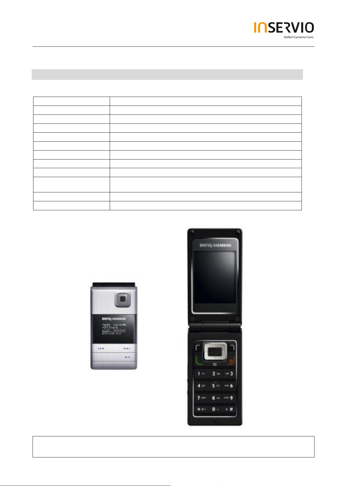
1 Key Feature
System
Battery
Stand – by Time
Talking Time
Antenna
Main Display
Sub - Display
Storage
Camera
Connectivity
Memory Slot
Processor
• Tri-Band GSM 900/1800/1900
• Li-Ion 750 mAh
• Up to 225h
• Up to 3 h
• Integrated
• 262, 144 TFT, 176x220 pixels, 2.2 inches
• White OLED, 128 x 64 pixels
• 24 MB
• 2.0 megapixel, 3 x linear digital zoom
• USB 1.1, Bluetooth: Object Push Profile, Object
Exchange, Handsfree Profile, Headset Profile
• MicroSD
• TI
Technical Documentation
TD_Repair_L1-L3_CF61_R1.0.pdf Page 3 of 51
Created by inservio GmbH for BenQ mobile GmbH & Co. OHG - Company Confidential2006©inservio
08/2006
Page 4
7
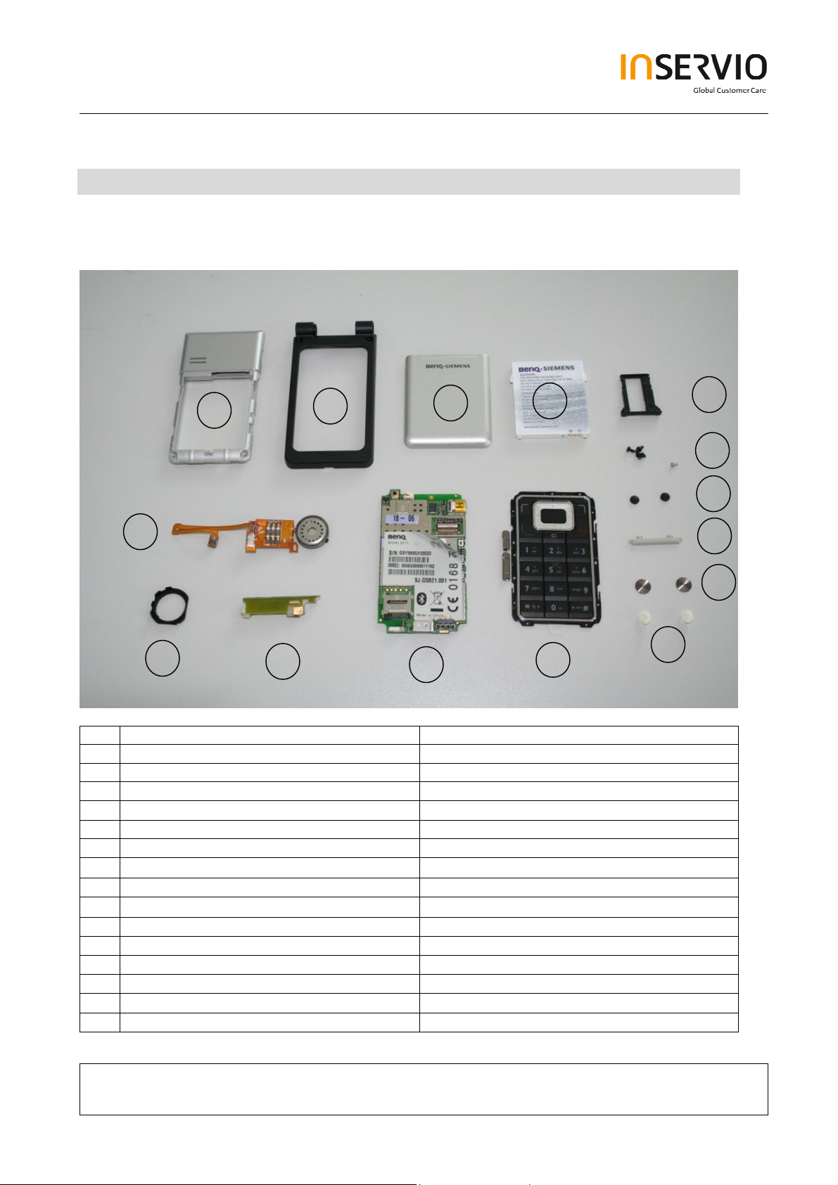
2 Spare Part Overview of EF71
Overview Upper Parts
2
3
5
6
15
14
13
12
11
10
No. Description CM Order Number
1. Lower Base Case Shell Tbd.
2. Upper Base Case Shell Tbd.
3. Battery Cover Tbd.
4. Battery Tbd.
5. Transflash card holder Tbd.
6. Base Screws Tbd.
7.
Screw Cover
Tbd.
8. Side Key Left Tbd.
9.
Screw Cover
Tbd.
10. Screw caps Tbd.
11. Keypad Tbd.
12. RF Control Board Tbd.
13. Side Key PCB Tbd.
14. Rubber gasket Tbd.
15. Vibra Alert Tbd.
8
Technical Documentation
08/2006
TD_Repair_L1-L3_CF61_R1.0.pdf Page 4 of 51
Created by inservio GmbH for BenQ mobile GmbH & Co. OHG - Company Confidential2006©inservio
Page 5
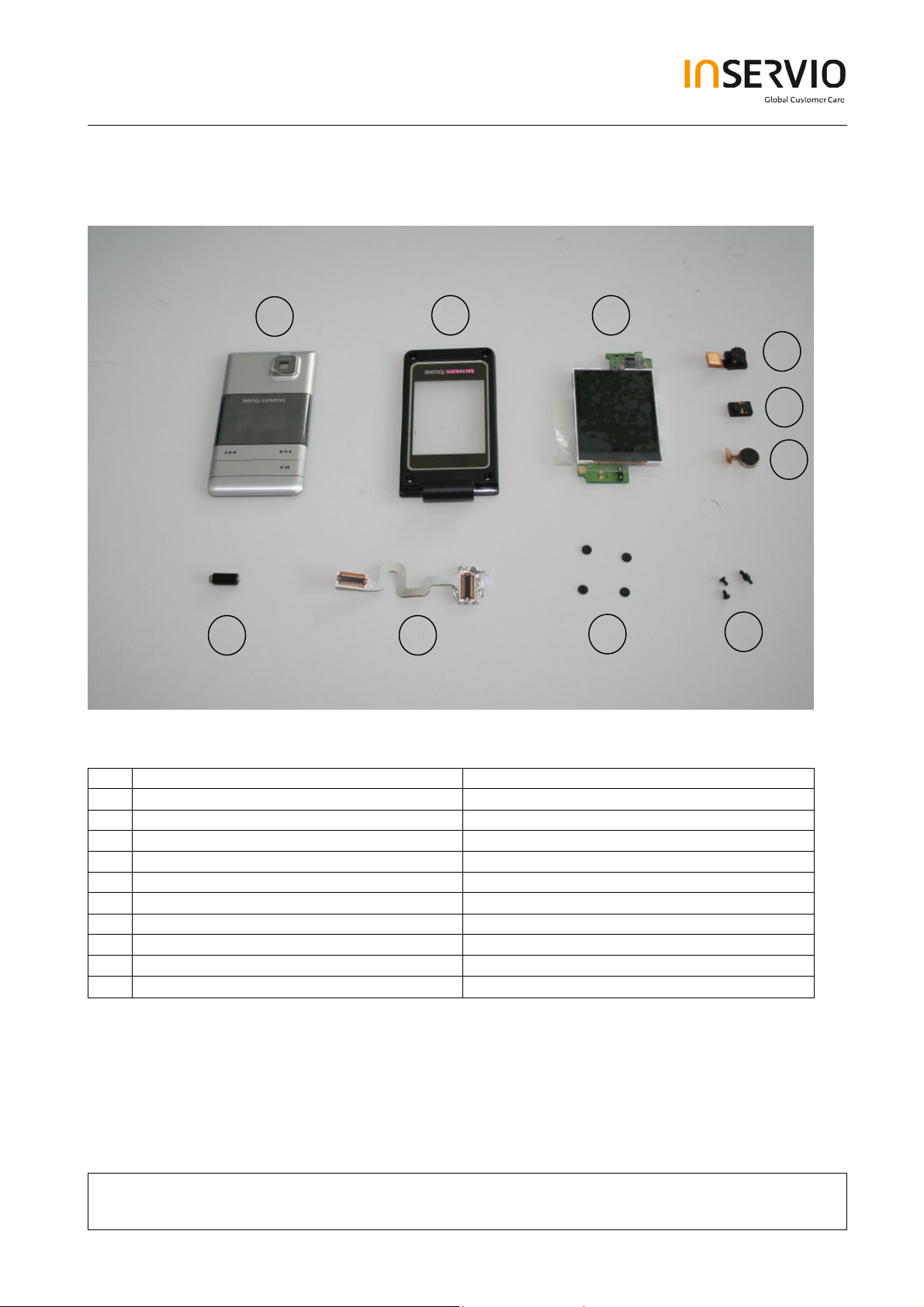
Overview Lower Parts
16
17
18
19
20
21
25
24
23
22
No. Description CM Order Number
16. Lift Case Cap Tbd.
17. Upper Lift Case Shell Tbd.
18. Display Module Tbd.
19. Camera Module Tbd.
20. Earpiece Tbd.
21. ??? Tbd.
22. Lift Screws Tbd.
23. Screw Cover Tbd.
24. Flex Cable Tbd.
Hinge Tbd.
25.
Technical Documentation
08/2006
TD_Repair_L1-L3_CF61_R1.0.pdf Page 5 of 51
Created by inservio GmbH for BenQ mobile GmbH & Co. OHG - Company Confidential2006©inservio
Page 6
3 Disassembly of EF71
All repairs as well as disassembling and assembling have to be carried out in an ESD
protected environment and with ESD protected equipment/tools. For all activities the
international ESD regulations have to be considered.
For more details please check information in c – market
https://market.benqmobile.com/SO/welcome.lookup.asp
There you can find the document “ESD Guideline”.
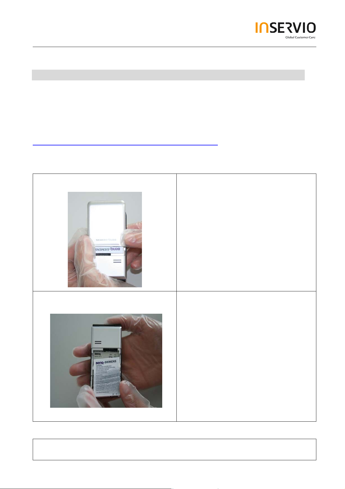
Step 1
Step 2
Remove Battery Cover.
Remove Battery.
Technical Documentation
TD_Repair_L1-L3_CF61_R1.0.pdf Page 6 of 51
Created by inservio GmbH for BenQ mobile GmbH & Co. OHG - Company Confidential2006©inservio
08/2006
Page 7
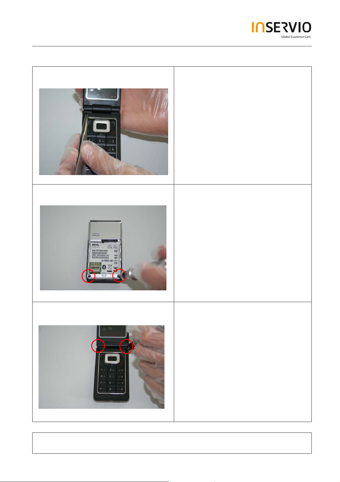
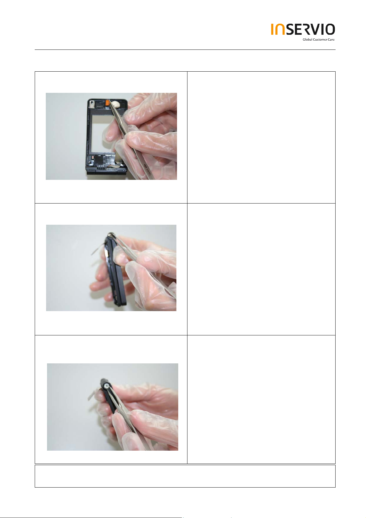
Step 3
Step 4
Remove Screw Cover by
using Tweezers.
Remove screws with the Torque –
Screwdriver T5+
Step 5
Remove screws with the Torque –
Screwdriver T5+
Technical Documentation
TD_Repair_L1-L3_CF61_R1.0.pdf Page 7 of 51
Created by inservio GmbH for BenQ mobile GmbH & Co. OHG - Company Confidential2006©inservio
08/2006
Page 8
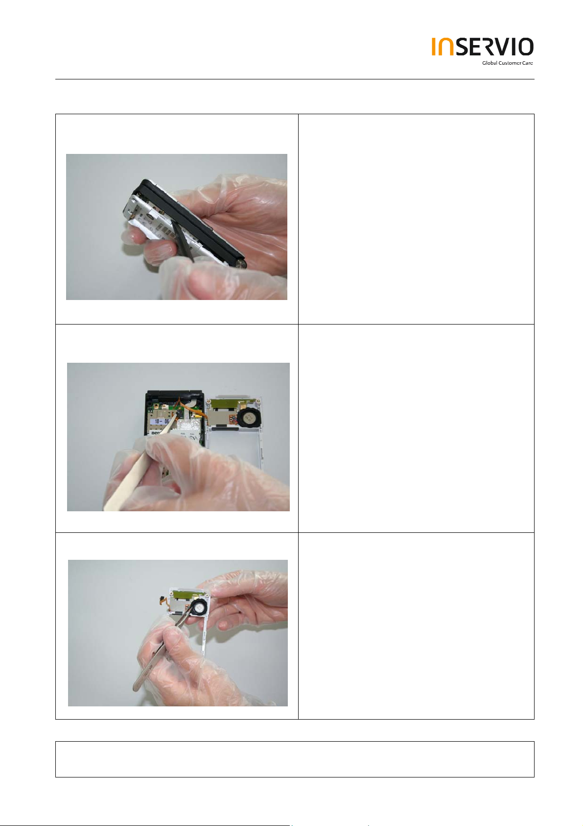
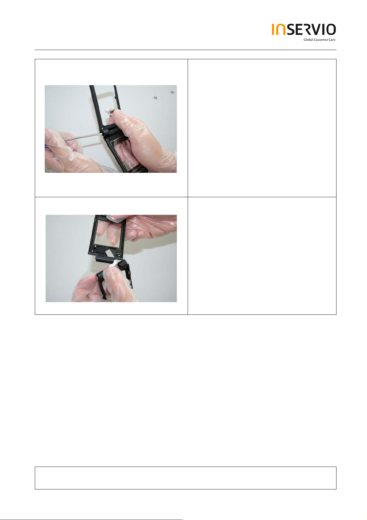
Step 6
Step 7
Remove Lower Base Case Shell with the
Alternative Opening Tool carefully.
Use Tweezers to disconnect the Flex
Cable from the RF Control Board socket.
Step 8
Remove rubber gasket from ringer.
Technical Documentation
TD_Repair_L1-L3_CF61_R1.0.pdf Page 8 of 51
Created by inservio GmbH for BenQ mobile GmbH & Co. OHG - Company Confidential2006©inservio
08/2006
Page 9
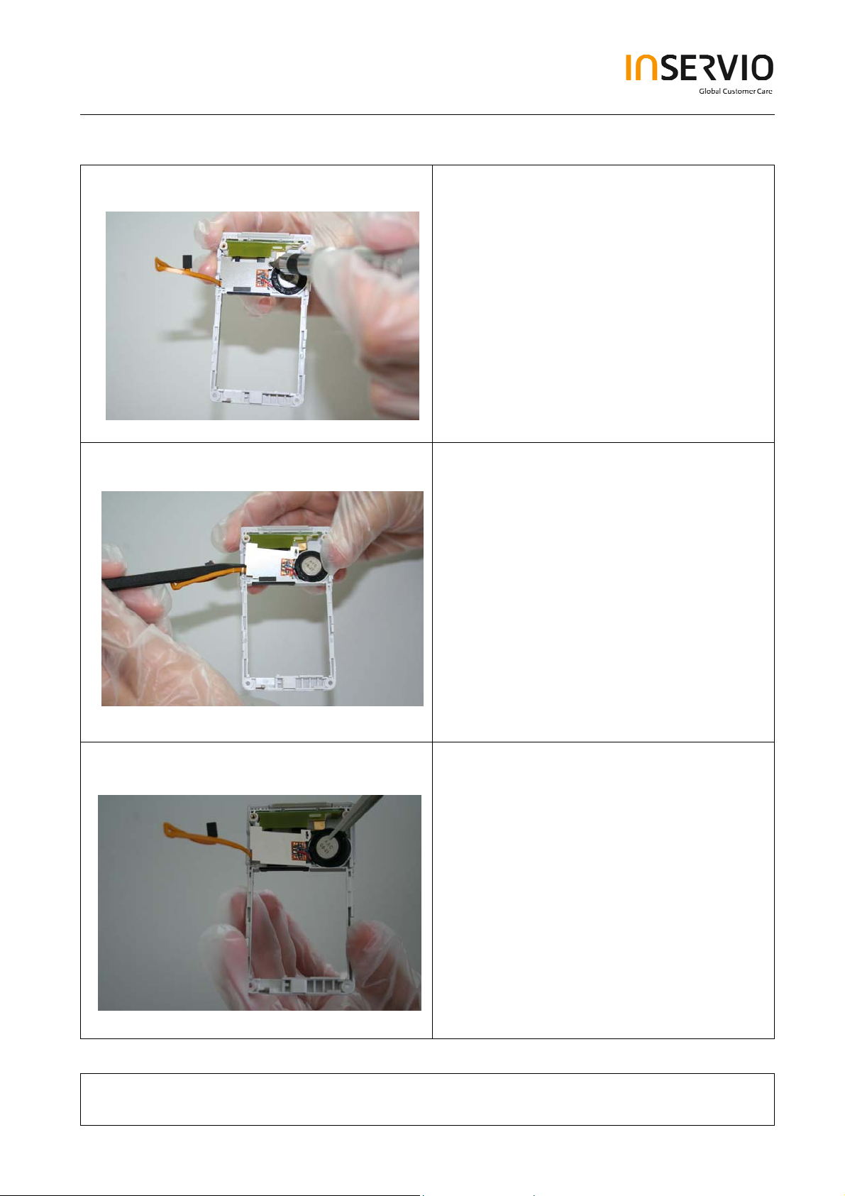
Step 9
Step 10
Remove Screws with the Torque –
Screwdriver
Remove Vibra Alert
with the Alternative Opening Tool carefully
Step 11
Technical Documentation
TD_Repair_L1-L3_CF61_R1.0.pdf Page 9 of 51
Created by inservio GmbH for BenQ mobile GmbH & Co. OHG - Company Confidential2006©inservio
08/2006
Page 10
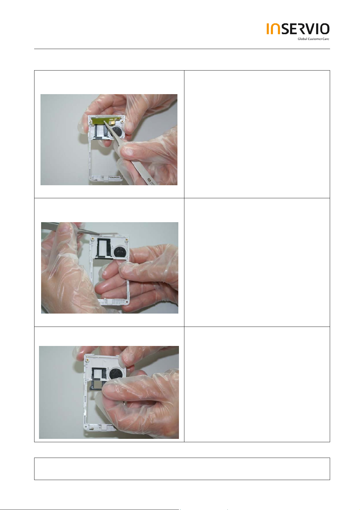
Step 12
Step 13
Remove the antenna PCB.
Remove the Side Key .
Step 14
Remove Transflash card holder
Technical Documentation
TD_Repair_L1-L3_CF61_R1.0.pdf Page 10 of 51
Created by inservio GmbH for BenQ mobile GmbH & Co. OHG - Company Confidential2006©inservio
08/2006
Page 11
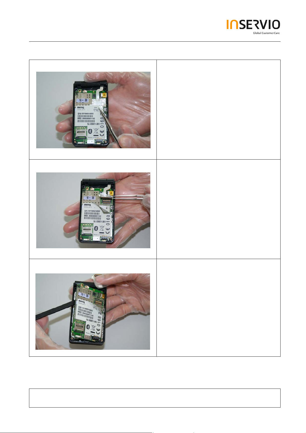
Step 15
Step 16
.
Step 17
Remove the Keypad PCB.
Technical Documentation
TD_Repair_L1-L3_CF61_R1.0.pdf Page 11 of 51
Created by inservio GmbH for BenQ mobile GmbH & Co. OHG - Company Confidential2006©inservio
08/2006
Page 12
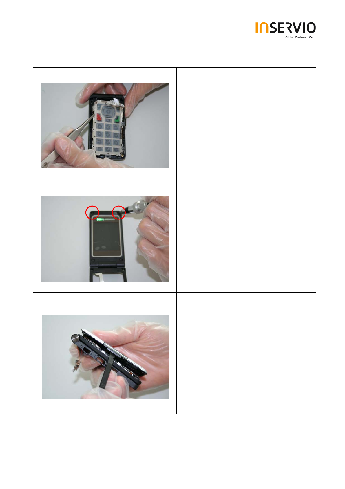
Step 18
Step 19
Remove the Keypad by using Tweezers.
Remove screws with the Torque –
Screwdriver T5+.
.
Step 20
Remove Lower Lift Case Cap by using the
Alternative Opening Tool carefully.
Technical Documentation
TD_Repair_L1-L3_CF61_R1.0.pdf Page 12 of 51
Created by inservio GmbH for BenQ mobile GmbH & Co. OHG - Company Confidential2006©inservio
08/2006
Page 13
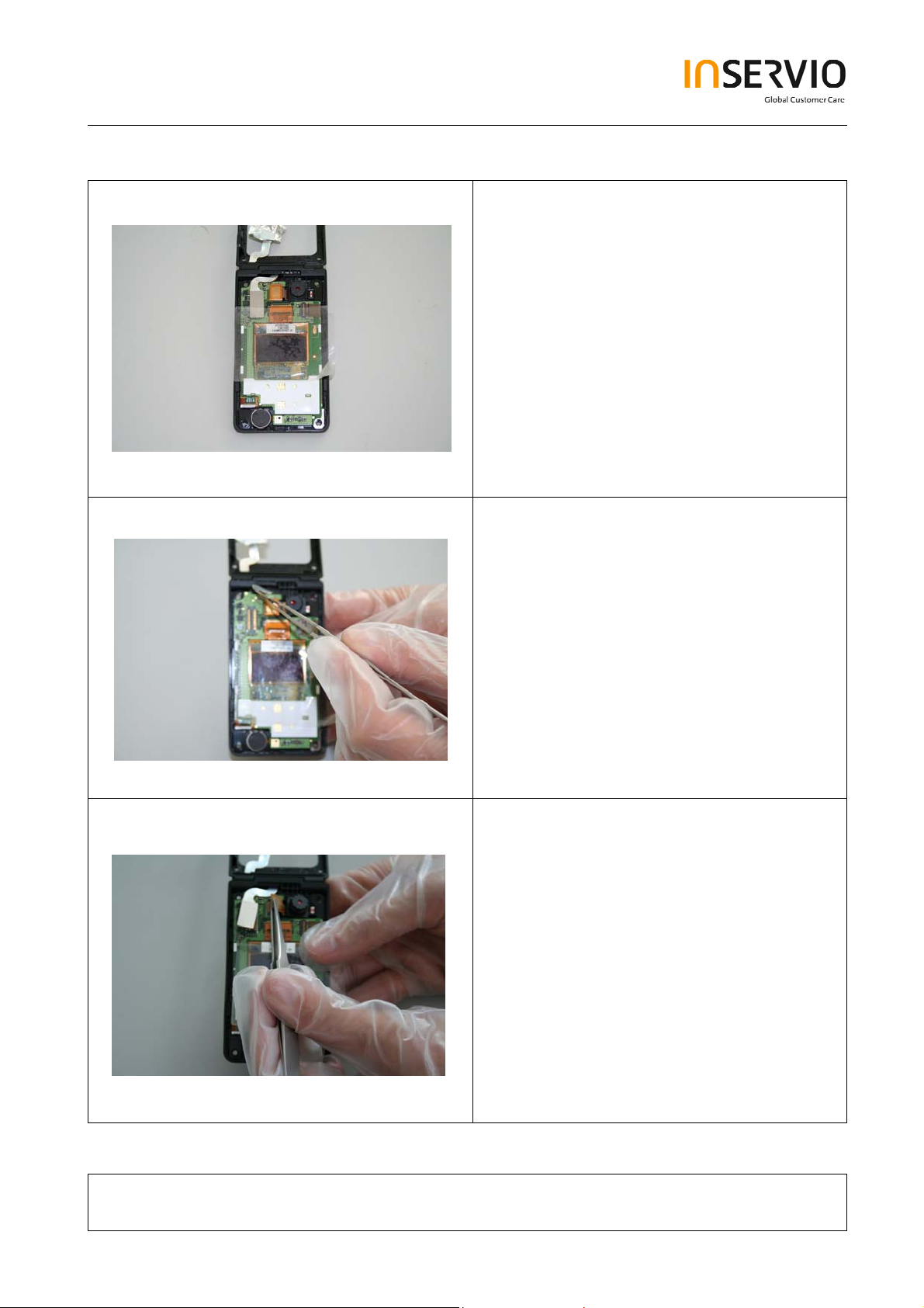
Step 21
Step 22
It is mandatory to place a Protection Foil
onto the Display.
Disconnect the Flex Cable.
Step 23
Remove the Camera Module by
disconnecting it from the socket.
Technical Documentation
TD_Repair_L1-L3_CF61_R1.0.pdf Page 13 of 51
Created by inservio GmbH for BenQ mobile GmbH & Co. OHG - Company Confidential2006©inservio
08/2006
Page 14

Step 24
Step 25
It is mandatory to place a Protection Foil
onto the Display to avoid scratches.
Step 26
Remove Vibra carefully by using tweezers
Technical Documentation
TD_Repair_L1-L3_CF61_R1.0.pdf Page 14 of 51
Created by inservio GmbH for BenQ mobile GmbH & Co. OHG - Company Confidential2006©inservio
08/2006
Page 15
Step 27
Step 28
Remove hinge cap
Step 29
Technical Documentation
TD_Repair_L1-L3_CF61_R1.0.pdf Page 15 of 51
Created by inservio GmbH for BenQ mobile GmbH & Co. OHG - Company Confidential2006©inservio
08/2006
Page 16
Step 30
Step 31
Use the Hinge Tool very carefully to
remove the Upper Base Case Shell from
the Lower Lift Case Shell.
Take care of the Flex Cable, it easily rips.
.
Technical Documentation
TD_Repair_L1-L3_CF61_R1.0.pdf Page 16 of 51
Created by inservio GmbH for BenQ mobile GmbH & Co. OHG - Company Confidential2006©inservio
08/2006
Page 17

Step 32
Step 33
.
Remove the Ringer by using Tweezers
carefully.
Technical Documentation
TD_Repair_L1-L3_CF61_R1.0.pdf Page 17 of 51
Created by inservio GmbH for BenQ mobile GmbH & Co. OHG - Company Confidential2006©inservio
08/2006
Page 18

4 Assembly of EF71
Step 1
Step 2
Assemble the Hinge.
Assemble the Flex Cable. Take care of it!
Step 3
Insert the Flex Cable into the Lower Lift
Case Shell.
.
Technical Documentation
TD_Repair_L1-L3_CF61_R1.0.pdf Page 18 of 51
Created by inservio GmbH for BenQ mobile GmbH & Co. OHG - Company Confidential2006©inservio
08/2006
Page 19

Step 4
Step 5
Assemble the Lower Lift Case Shell and
the Upper Base Case Shell by using the
Hinge Tool.
Step 6
Assemble the Lower Lift Case Shell and
the Upper Base Case Shell by using the
Hinge Tool.
Technical Documentation
TD_Repair_L1-L3_CF61_R1.0.pdf Page 19 of 51
Created by inservio GmbH for BenQ mobile GmbH & Co. OHG - Company Confidential2006©inservio
08/2006
Page 20

Step 7
Step 8
Assemble Screw Cover by
using Tweezers.
Step 9
Assemble the vibra.
Technical Documentation
TD_Repair_L1-L3_CF61_R1.0.pdf Page 20 of 51
Created by inservio GmbH for BenQ mobile GmbH & Co. OHG - Company Confidential2006©inservio
08/2006
Page 21

Step 10
Step 11
Remove Display Foil.
Assemble the Display Module.
.
Step 12
Technical Documentation
TD_Repair_L1-L3_CF61_R1.0.pdf Page 21 of 51
Created by inservio GmbH for BenQ mobile GmbH & Co. OHG - Company Confidential2006©inservio
08/2006
Page 22

Step 13
Step 14
Step 15
Assemble the Camera Module by
connecting it to the socket.
Remove Display Foil.
Assemble Upper Lift Case and Lower Lift
Case.
Technical Documentation
TD_Repair_L1-L3_CF61_R1.0.pdf Page 22 of 51
Created by inservio GmbH for BenQ mobile GmbH & Co. OHG - Company Confidential2006©inservio
08/2006
Page 23

Step 16
Step 17
Step 18
Place screws by using the Torque –
Screwdriver T5+.
Assemble Keypad.
Technical Documentation
TD_Repair_L1-L3_CF61_R1.0.pdf Page 23 of 51
Created by inservio GmbH for BenQ mobile GmbH & Co. OHG - Company Confidential2006©inservio
08/2006
Page 24

Step 19
Step 20
Assemble the Side Key PCB by using
Tweezers.
Assemble Keypad PCB.
Step 21
Technical Documentation
TD_Repair_L1-L3_CF61_R1.0.pdf Page 24 of 51
Created by inservio GmbH for BenQ mobile GmbH & Co. OHG - Company Confidential2006©inservio
08/2006
Page 25

Step 22
Step 23
Assemble transflash card holder.
Assemble the Side Key by using
Tweezers.
Step 24
Assemble the antenna PCB by using
Tweezers.
.
Technical Documentation
TD_Repair_L1-L3_CF61_R1.0.pdf Page 25 of 51
Created by inservio GmbH for BenQ mobile GmbH & Co. OHG - Company Confidential2006©inservio
08/2006
Page 26

Step 25
Step 26
Assemble the Ringer-Alert by using
Tweezers.
Place screws by using the Torque –
Screwdriver T5+.
Step 27
Assemble rubber gasket.
Technical Documentation
TD_Repair_L1-L3_CF61_R1.0.pdf Page 26 of 51
Created by inservio GmbH for BenQ mobile GmbH & Co. OHG - Company Confidential2006©inservio
08/2006
Page 27

Step 28
Step 29
Connect flex cable connector.
Assemble the Lower Base Case Shell.
Step 30
Place screws with Torque – Screwdriver
T5+.
Technical Documentation
TD_Repair_L1-L3_CF61_R1.0.pdf Page 27 of 51
Created by in GmbH bile GmbH & Co. OHG - Company Confidential2006©inservio servio for BenQ mo
08/2006
Page 28

Step 31
Step 32
Place screws with Torque – Screwdriver
T5+.
.
Assemble Battery.
Step 33
Assemble Battery Cover.
Technical Documentation
TD_Repair_L1-L3_CF61_R1.0.pdf Page 28 of 51
Created by inservio GmbH for BenQ mobile GmbH & Co. OHG - Company Confidential2006©inservio
08/2006
Page 29

5 BenQ Service Equipment User Manual
Introduction
Every LSO repairing BenQ handset must ensure that the quality standards are
observed. BenQ has developed an automatic testing system that will perform all
necessary measurements. This testing system is known as:
BenQ Mobile Service Equipment
• For disassembling / assembling
Torque – Screwdriver
Part Number: F 30032 – P 228 – A1
• For SW UPDATE
Opening tool
(Case opening without destroying)
Part Number: F 30032 – P 38 – A1
Alternative Opening tool
Part Number: F30032 – P583 – A1
Tweezers
Torque – Screwdriver
Part Number: F 30032 – P 228 – A1
• For testing
All mobile phones have to be tested with the GRT – Software. The service partner
is responsible to ensure that all required hardware is available.
For additional Software and Hardware options as well as the supported GRT
equipment, please check the GRT User manual.
Technical Documentation
TD_Repair_L1-L3_CF61_R1.0.pdf Page 29 of 51
Created by inservio GmbH for BenQ mobile GmbH & Co. OHG - Company Confidential2006©inservio
08/2006
Page 30

6 Setup of the Software
Download of the required software:
Download the driver, the XCSD software mobile software (core-software and language files)
from the Technical Support Page:
https://market.benqmobile.com/so/welcome.lookup.asp
Installation of USB – Serial converter boot cable:
Start the “DataCableDrvInstaller.exe” file and follow the instructions of the installer.
Plug in the Data cable and follow the installation instructions to complete the process.
Check the Comport number of the data cable in the device manager.
(XCSD tool supports only Comport 1 to 10)
Technical Documentation
TD_Repair_L1-L3_CF61_R1.0.pdf Page 30 of 51
Created by inservio GmbH for BenQ mobile GmbH & Co. OHG - Company Confidential2006©inservio
08/2006
Page 31

Installation of XCSD tool:
Start “setup.exe” file and follow the instructions.
The installer creates a shortcut in the start menu bar. Start – Programs – XCSDTool_L1 BenQS
7 Software basic settings
Start the software (BenQS.exe). The XCSD tool will be shown on the screen
Select Model (for example see the screenshot below):
Technical Documentation
TD_Repair_L1-L3_CF61_R1.0.pdf Page 31 of 51
Created by inservio GmbH for BenQ mobile GmbH & Co. OHG - Company Confidential2006©inservio
08/2006
Page 32

Select Com port (Setting – Com port):
8 Software Download procedure
Select Download Option (View – Download):
Technical Documentation
TD_Repair_L1-L3_CF61_R1.0.pdf Page 32 of 51
Created by inservio GmbH for BenQ mobile GmbH & Co. OHG - Company Confidential2006©inservio
08/2006
Page 33

Select Program Code (example: E22 1 11710.mot) and
Language Pack (example E22 L 11711.mot)
Status bar colour scheme:
yellow waiting for update
blue update in progress
red error occurred
black Comport not
available
green Update successful
Connect mobile phone with data cable. Phone must be switched off. Click on “Start”
button and press the power on button on the handset to start the download. During
download process status bar shows the state of the process of P = Program code, L =
Language file and S = Set default (if activated). After successful SW download, the
status bar of the used Com port is changed to green.
Erase of customer data:
Select the “Power-off set default” option to erase all customer data of the phone during the
download process.
Click the “Set E2p” to erase the customer data without software update.
SW files naming rules:
Program Code E22111710
Language Pack E22L11711
E22 Project name
117 Program Code
L Language Pack
117 Version 1.17
10/11 Program Code ID
Technical Documentation
08/2006
TD_Repair_L1-L3_CF61_R1.0.pdf Page 33 of 51
Created by inservio GmbH for BenQ mobile GmbH & Co. OHG - Company Confidential2006©inservio
Page 34

9 Download PPF (Handset configuration)
Select write PPF option (View – Write PPF):
Select Database File (example: E22111710.bin) and
PPF File (example benq_m315_twn.ppf)
Connect mobile phone with data cable. Phone must be switched on. Click to “Write PPF”
button to start the process.
Confirmation about successful write of PPF appears after process is completed.
Don’t activate
Technical Documentation
TD_Repair_L1-L3_CF61_R1.0.pdf Page 34 of 51
Created by inservio GmbH for BenQ mobile GmbH & Co. OHG - Company Confidential2006©inservio
08/2006
Page 35

10 Backup and Restore of Wap and Network Setting
Select Back and Restore of Wap and Network Settings option
(View – Wap/Network Bkp/Restore):
Technical Documentation
TD_Repair_L1-L3_CF61_R1.0.pdf Page 35 of 51
Created by inservio GmbH for BenQ mobile GmbH & Co. OHG - Company Confidential2006©inservio
08/2006
Page 36

Select Database File (example: E22111710.bin) and
Setting File (create new txt file and rename it to ntk file for settings
backup)
Connect mobile phone with data cable. Phone must be switched off.
Click to “Backup” button to start the transfer the settings into the selected file.
Click to “Restore” button to start the transfer from selected file into handset.
11 Backup and Restore of Media Center content
Select Back and Restore of Media center (View – Media center Bkp/Restore):
Technical Documentation
TD_Repair_L1-L3_CF61_R1.0.pdf Page 36 of 51
Created by inservio GmbH for BenQ mobile GmbH & Co. OHG - Company Confidential2006©inservio
08/2006
Page 37

Select Media File (create new txt file and rename it to mmd file)
Connect mobile phone with data cable. Phone must be switched on.
Click to “Backup” button to start the transfer the settings into the selected file.
Click to “Restore” button to start the transfer from selected file into handset.
12 Unlock Tool
Select Unlock tool function (View – Unlock Tool):
Technical Documentation
08/2006
TD_Repair_L1-L3_CF61_R1.0.pdf Page 37 of 51
Created by inservio GmbH for BenQ mobile GmbH & Co. OHG - Company Confidential2006©inservio
Page 38

Select Database File (example: E22111710.bin)
Click to “Show PW” button to get the codes.
Unlock the codes in the mobile phone menu.
Click to “Hide PW” button to hide the codes.
Technical Documentation
TD_Repair_L1-L3_CF61_R1.0.pdf Page 38 of 51
Created by inservio GmbH for BenQ mobile GmbH & Co. OHG - Company Confidential2006©inservio
08/2006
Page 39

13 JPICS (Java based Product Information Controlling System)
Overview
Technical Documentation
TD_Repair_L1-L3_CF61_R1.0.pdf Page 39 of 51
The following functions are available for the LSO:
• General mobile information
• Generate PINCODE
• Generate SIMLOCK – UNLOCK – Code
• Print IMEI labels
08/2006
Created by inservio GmbH for BenQ mobile GmbH & Co. OHG - Company Confidential2006©inservio
Page 40

The access to the JPICS server which is located in Kamp – Lintfort is protected by chip
card and in addition using secure socket layer (SSL) connection.
The JPICS server is only available for authorized users with a specially coded smart
card. These smart cards and the administration of the JPICS web server and the PICS
database – server can only be provided by the JPICS – TRUST – Center of the
responsible department
in Kamp – Lintfort.
In case of any questions or requests concerning smart cards or administration of the
databases please ask your responsible BenQ Customer Care Manager.
Technical Documentation
08/2006
TD_Repair_L1-L3_CF61_R1.0.pdf Page 40 of 51
Created by inservio GmbH for BenQ mobile GmbH & Co. OHG - Company Confidential2006©inservio
Page 41

Installation overview
The following installation description assumes that a web browser is already installed.
JPICS is tested with the following browsers:
Internet Explorer Version 5.5 and higher
1.
Netscape Version 6 and higher
2.
For further information regarding supported browsers, browser version and supported
operating systems, see the
Sun FAQ’s.
Here is a step by step instruction to install all the required components:
It is necessary to follow this order!
Smart Card Reader (Omnikey: Cardman 2020 USB or Cardman 3121 USB)
1.
CardOS interface (Siemens Version 3.0 B)
2.
Java Runtime Environment (Sun)
3.
Java additional components
4.
Every user is responsible for a proper installation matching the license
agreements.
For installation and further access you need the following:
1. The JPICS Installation – CD
2. The Smart Card JPICS.
Remark: We recommend using Cardman 2020 USB or Cardman 3121 USB. Serial card
readers are not supported!!!
Technical Documentation
TD_Repair_L1-L3_CF61_R1.0.pdf Page 41 of 51
Created by inservio GmbH for BenQ mobile GmbH & Co. OHG - Company Confidential2006©inservio
08/2006
Page 42

Generate Codes
In the JPICS application you can choose to generate:
• Masterphone codes
• Simlock – Unlock – Codes
Masterphone codes
The Masterphone code is used to unlock blocked mobiles.
Masterphone codes can only be supplied for mobiles which have been delivered in a
regular manner.
Technical Documentation
TD_Repair_L1-L3_CF61_R1.0.pdf Page 42 of 51
Created by inservio GmbH for BenQ mobile GmbH & Co. OHG - Company Confidential2006©inservio
08/2006
Page 43

Simlock – Unlock – Code
The Simlock – Unlock – Codes can only be generated if the following conditions are
given:
• Mobile must have an active Simlock inside.
• The user must be given the authorization to obtain Simlock – Unlock – Codes
for the variant of the operator to which the mobile was delivered last time.
Technical Documentation
TD_Repair_L1-L3_CF61_R1.0.pdf Page 43 of 51
Created by inservio GmbH for BenQ mobile GmbH & Co. OHG - Company Confidential2006©inservio
08/2006
Page 44

Printing IMEI label
The module “printing IMEI label” offers the possibility to re-print IMEI labels for
mobiles again.
You are able to print 1 label in just one step.
To prevent that misaligned labels are being printed, the setting “Print test labels =
” is
activated by default. After having printed a well aligned test label you can uncheck the
setting and print the correct label.
Hint:
For correct printing of IMEI labels you must have a Zebra – label printer with special
material that fits for label printing. This printer has to be connected to local LPT1 printer
port
(also see Installation of IMPRINT) and MUST feature a printing resolution of 300dpi.
Technical Documentation
TD_Repair_L1-L3_CF61_R1.0.pdf Page 44 of 51
Created by inservio GmbH for BenQ mobile GmbH & Co. OHG - Company Confidential2006©inservio
08/2006
Page 45

14 International Mobile Equipment Identity, IMEI
The mobile equipment is uniquely identified by the International Mobile Equipment
Identity, IMEI, which consists of 15 digits. Type approval granted to a type of mobile is
allocated 6 digits. The final assembly code is used to identify the final assembly plant
and is assigned with 2 digits. 6 digits have been allocated for the equipment serial
number for manufacturer and the last digit is spare.
CF61 series IMEI label is accessible by removing the battery.
Re – use of IMEI label is possible by using a hair – dryer to remove the IMEI label.
Date code is shown on IMEI label: Detailed description on how to read date code is
given in Annex 2.
To display the IMEI number, exit code and SW/HW version, key: * # 300 #
Code *#301# activates self diagnosis.
Technical Documentation
TD_Repair_L1-L3_CF61_R1.0.pdf Page 45 of 51
Created by inservio GmbH for BenQ mobile GmbH & Co. OHG - Company Confidential2006©inservio
08/2006
Page 46

15 General Testing Information
General Information
The technical instruction for testing GSM mobile phones is to ensure the best repair
quality.
Validity
This procedure is to apply for all from Siemens AG authorized level 2 up to 2.5e
workshops.
Procedure
All following checks and measurements have to be carried out in an ESD protected
environment and with ESD protected equipment/tools. For all activities the international
ESD regulations have to be considered.
Get delivery:
Ensure that every required information like fault description, customer data a.s.o.
is available.
Ensure that the packing of the defective items is according to packing
requirements.
Ensure that there is a description available, how to unpack the defective items
and what to do with them.
Enter data into your database:
(Depends on your application system)
Ensure that every data, which is required for the IRIS-Reporting is available in
your database.
Ensure that there is a description available for the employees how to enter the
data.
Technical Documentation
TD_Repair_L1-L3_CF61_R1.0.pdf Page 46 of 51
Created by inservio GmbH for BenQ mobile GmbH & Co. OHG - Company Confidential2006©inservio
08/2006
Page 47

Incoming check and check after assembling:
!! Verify the customers fault description!!
After a successful verification pass the defective item to the responsible
troubleshooting group.
If the fault description can not be verified, perform additional tests to save time
and to improve repair quality.
- Switch on the device and enter PIN code if necessary unblock phone.
- Check the
- Check the display for error in
function of all keys including side keys.
line and row, and for illumination.
- Check the ringer/loudspeaker acoustics by individual validation.
- Perform a GSM Test as described on page 36.
Check the storage capability:
Check internal resistance and capacity of the battery.
Check battery charging capability of the mobile phone.
Check charging capability of the power supply.
Check current consumption of the mobile phone in different mode.
Visual inspection:
Check the entire board for liquid damages.
Check the entire board for electrical damages.
Check the housing of the mobile phone for damages.
SW update:
Carry out a software update and data reset according to the master tables and
operator/customer requirements.
Repairs:
The disassembling as well as the assembling of a mobile phone has to be
carried out by considering the rules mentioned in the dedicated manuals. If
special equipment is required the service partner has to use it and to ensure
the correct function of the tools.
If components and especially soldered components have to be replaced all
rules mentioned in dedicated manuals or additional information e.g. service
information have to be considered
Technical Documentation
TD_Repair_L1-L3_CF61_R1.0.pdf Page 47 of 51
Created by inservio GmbH for BenQ mobile GmbH & Co. OHG - Company Confidential2006©inservio
08/2006
Page 48

GSM Test:
With the availability of the GRT Test /Alignment software, this tool has to be used to
perform the outgoing test!
>Connect the mobile/board via internal antenna (antenna coupler) and external antenna
(car cradle/universal antenna clip) to a GSM tester
>Use a Test SIM
For Triple Band phones use a separate test case, if the test software allows only one
handover.
Skip the GSM Band test cases if not performed by the mobile phone
Example: 1. Test file Band 1 = GSM900 / Band 2 = GSM1800
2. Test file Band 1 = GSM1900
Internal Antenna
Test case Parameter Measurements Limits
1 Location Update • GSM Band 1
• BS Power = -55 dBm
• middle BCCH
2 Call from BS • low TCH
• highest PCL
• BS Power = -75 dBm
• middle BCCH
3 TX GSM Band 1 • low TCH
• highest PCL
• BS Power = -75 dBm
• middle BCCH
4 Handover to GSM Band 2
Including Handover
Check
5 TX GSM Band 2 • low TCH
6 Call release from BS
• highest PCL0
• BS Power = -75 dBm
• middle BCCH
• Display check • individual
check
• Ringer/Loudspeaker
check
• Frequency Error
• Phase Error RMS
• Phase Error Peak
• Average Power
• Power Time Template
• Frequency Error
• Phase Error RMS
• Phase Error Peak
• Average Power
• Power Time Template
• individual
check
• GSM Spec.
• GSM Spec.
Technical Documentation
08/2006
TD_Repair_L1-L3_CF61_R1.0.pdf Page 48 of 51
Created by inservio GmbH for BenQ mobile GmbH & Co. OHG - Company Confidential2006©inservio
Page 49

External Antenna
7 Call from MS • GSM900
• high TCH
• second highest PCL
• BS Power = -75 dBm
• middle BCCH
8 TX GSM Band 1 • high TCH
• second highest PCL
• BS Power = -75 dBm
• middle BCCH
9 RX GSM Band 1 • high TCH
• BS Power = -102 dBm
• 50 Frames
• middle BCCH
10 Handover to GSM Band 2
Including Handover
Check
11 TX GSM Band 2 • high TCH
12 RX GSM Band2 • high TCH
13 Call release from MS
• second highest PCL
• BS Power = -75 dBm
• middle BCCH
• BS Power = -102 dBm
• 50 Frames
• middle BCCH
• Keyboard check • individual
check
• Frequency Error
• Phase Error RMS
• Phase Error Peak
• Average Power
• Power Time Template
• RX Level
• RX Qual
• BER Class Ib
• BER Class II
• BER Erased Frames
• Frequency Error
• Phase Error RMS
• Phase Error Peak
• Average Power
• Power Time Template
• RX Level
• RX Qual
• BER Class Ib
• BER Class II
• BER Erased Frames
• GSM Spec.
• GSM Spec.
• GSM Spec.
• GSM Spec.
Final Inspection:
The final inspection contains:
1) A 100% network test (location update, and set up call).
2) Refer to point 3.3.
3) A random sample checks of:
- Data reset (if required)
- Optical appearance
- complete function
4) Check if PIN-Code is activated (delete the PIN-Code if necessary).
Basis is the international standard of DIN ISO 2859.
Use Normal Sample Plan Level II and the Quality Border 0,4 for LSO.
Remark: All sample checks must be documented.
Technical Documentation
08/2006
TD_Repair_L1-L3_CF61_R1.0.pdf Page 49 of 51
Created by inservio GmbH for BenQ mobile GmbH & Co. OHG - Company Confidential2006©inservio
Page 50

Annex 1
Test SIM Card
There are two different “Test SIM Cards” in use:
1) Test SIM Card from the company “ORGA”
Pin 1 number: 0000
PUK 1 : 12345678
Pin 2 number: 0000
PUK 2 : 23456789
2) Test SIM Card from the company “T-D1”
Pin 1 number: 1234
PUK : 76543210
Pin 2 number: 5678
PUK 2 : 98765432
Technical Documentation
TD_Repair_L1-L3_CF61_R1.0.pdf Page 50 of 51
Created by inservio GmbH for BenQ mobile GmbH & Co. OHG - Company Confidential2006©inservio
08/2006
Page 51

Annex 2
Device Date Code overview
GSN rule:
(ex: GS11500001TG0)
GS 1 9 5 00001 TG0
Big class Date Month Year S/N Factory
Based on the definition above, GSC55... below means 2005/05/12.
Technical Documentation
TD_Repair_L1-L3_CF61_R1.0.pdf Page 51 of 51
Created by inservio GmbH for BenQ mobile GmbH & Co. OHG - Company Confidential2006©inservio
08/2006
 Loading...