

Page 1

Page 2

Is there ...
...any technical problem or other
question you need clarified?
Please contact:
one of our IT Service Shops
•
your sales partner
•
your sales office
•
The addresses of our IT Service Shops
can be found in the guarantee coupon
booklet.
The latest information on our products,
tips, updates, etc., can be found on the
Internet under:
http://www.sni.de/pc
... anything you want to tell us about this
manual?
Please send us your comments quoting
the order number of the manual.
Siemens Nixdorf Informationssysteme AG
User Documentation Department
OEC BS2 OS ID4
Otto-Hahn-Ring 6
D-81730 München
Page 3

Page 4

! "
# $
%&
' () * +,
--./0
123-. 45
6(&7 (8
9 ,
+, 2./3 2.&/3
A26361-D1005-Z120-1-7619
Page 5

Product Description
Using the BIOS Setup
Program
System board D1005
Technical Manual
Installing Motherboard
Options
Error and Information
Messages
Technical Reference
Upgrading the BIOS
Index
October 1997 edition
Page 6

Your training needs?
The Siemens Nixdorf Training Centers offer you a wide range of training courses
in information technology and on IT products and other subjects - onsite near to
your workplace or offsite at one of our training centers.
Contact us for information on consulting, course schedules and selfstudy material
Either fax (which is the fastest way:
Fax: ..49 89 636-42945
Or write to:
Siemens Nixdorf Informationssysteme AG
Training Center, Beratungsservice
D-81730 München
Intel and Pentium are registered trademarks and OverDrive is a trademark of Intel
Corporation, USA.
Microsoft, MS, MS-DOS, Windows and Windows 95 are registered trademarks of Microsoft
Corporation.
PS/2 and OS/2 Warp are registered trademarks of International Business Machines, Inc.
All other trademarks referenced are the trademarks or registered trademarks of their
respective owners, whose protected rights are acknowledged.
Copyright Siemens Nixdorf Informationssysteme AG 1997.
All rights, including rights of translation, reproduction by printing, copying or similar methods,
even of parts are reserved.
Offenders will be liable for damages.
All rights, including rights created by patent grant or registration of a utility model or design,
are reserved.
Delivery subject to availability; right of technical modifications reserved.
Page 7

Contents
Product Description ..............................................................................................1
Microprocessor........................................................................................................1
Main Memory (DRAM).............................................................................................1
PCI/IDE Peripheral Interface ...................................................................................4
I/O Features.............................................................................................................4
BIOS Features.........................................................................................................5
PCI Auto-configuration .....................................................................................5
IDE Auto-configuration .....................................................................................5
ISA Plug and Play Capability............................................................................5
Security Features .............................................................................................5
BIOS Upgrades ................................................................................................6
Expansion Slots.......................................................................................................6
Real-time Clock and CMOS RAM............................................................................6
Battery .....................................................................................................................6
Speaker ...................................................................................................................6
Fan Connectors.......................................................................................................7
USB Interface Support.............................................................................................7
Audio Subsystem.....................................................................................................8
Hardware Monitor Option.........................................................................................8
Using the BIOS Setup Program............................................................................9
Overview of the BIOS Setup Program.....................................................................9
Main Screen...........................................................................................................11
Floppy Options Subscreen .............................................................................13
Floppy Access................................................................................................14
Primary/Secondary IDE Master/Slave Configuration Subscreens..................14
Boot Options Subscreen.................................................................................16
Second Boot Device.......................................................................................17
Advanced Screen ..................................................................................................21
Peripheral Configuration Subscreen...............................................................22
Advanced Chipset Configuration Subscreen..................................................27
Power Management Configuration Subscreen...............................................29
Plug and Play Configuration Subscreen.........................................................30
Event Logging Configuration Subscreen........................................................32
Security Screen .....................................................................................................36
Exit Screen ............................................................................................................39
Installing and Configuring Motherboard Options.............................................41
Before You Begin...................................................................................................41
Jumpers.................................................................................................................42
A26361-D1005-Z120-2-7619
Page 8

Contents
Jumpers for Setup Program Functions ..................................................................43
How to Disable Access to the Setup Program................................................44
How to Enable Access to the Setup Program.................................................45
How to Clear CMOS RAM...............................................................................45
How to Install a Processor .....................................................................................46
Install the Processor .......................................................................................46
Remove the Installed Processor.....................................................................48
Set the Processor Speed Jumpers .................................................................48
How to Install Memory............................................................................................49
How to Remove Memory........................................................................................52
How to Replace the Battery ...................................................................................53
Error messages....................................................................................................55
BIOS Beep Codes..................................................................................................55
PCI Configuration Error Messages ........................................................................56
BIOS Error Messages............................................................................................57
ISA NMI Messages ................................................................................................59
Technical Reference............................................................................................61
Motherboard Connectors .......................................................................................61
CD-ROM Audio Connector..............................................................................61
Telephony Connector......................................................................................61
Wavetable Connector .....................................................................................62
Telephony Connector......................................................................................62
Audio Line In Connector .................................................................................62
Fan 1 Connector.............................................................................................63
Fan 3 Connector.............................................................................................63
Chassis Security Connector............................................................................63
Front Panel Connectors..................................................................................64
Motherboard Resources.........................................................................................66
Memory Map...................................................................................................66
I/O Map...........................................................................................................67
PCI Configuration Space Map ........................................................................70
DMA Channels................................................................................................70
Interrupts .........................................................................................................71
Upgrading the BIOS.............................................................................................73
Record the Current BIOS Settings.........................................................................73
How to Upgrade the BIOS......................................................................................73
Make a Copy of the Current BIOS ..................................................................73
Upgrade the BIOS...........................................................................................74
How to Recover the BIOS If an Upgrade Fails.......................................................75
Index......................................................................................................................77
A26361-D1005-Z120-2-7619
Page 9

Product Description
This chapter describes the features of the motherboard. The remaining chapters
explain how to:
Use the BIOS Setup program to modify the motherboard's configuration
•
Install components like processors or memory
•
Interpret error messages you might encounter while running the computer
•
Figure 1 shows the components on the motherboard. Figure 2 shows the back
panel connectors on the motherboard.
All functions are described here, including those not currently supported.
Please note that the BIOS delivery status does not always match the specified
default values.
Microprocessor
The motherboard supports Intel Pentium II processors with MMX technology
and secondary (L2) cache.
The Pentium II processor is packaged in a Single Edge Contact (S.E.C.) cartridge
that mounts in the Slot 1 processor connector on the motherboard.
Main Memory (DRAM)
The motherboard supports up to 256 MB of DRAM. DRAM is implemented through
four 72-pin SIMM sockets. The motherboard contains four SIMM sockets. To add
memory to the motherboard, see
the motherboard's main memory map, see
Memory error checking and correction is supported with parity or ECC SIMMs.
Parity or ECC SIMMs are automatically detected; however, the user must enter
Setup to configure SIMMs for either parity or ECC operation. Parity memory will
detect single-bit errors. ECC memory will detect multi-bit errors and correct singlebit errors. Errors may be generated by a defective memory module, mixing
different speed memory modules, or by DMA or memory conflicts.
A26361-D1005-Z120-2-7619
Installing and configuring motherboard options
Technical Reference
.
. For
1
Page 10
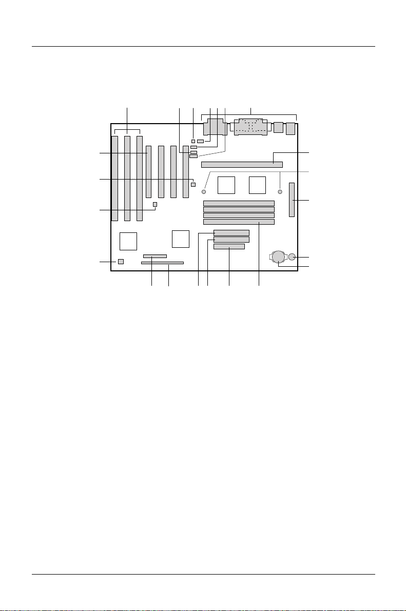
Product Description
Figure 1. Motherboard Components
A F
V
U
T
S
R N
A = ISA connectors
B = CD-ROM audio connector
C = Telephony connector
D = Wavetable connector
E = Telephony connector
F = Audio line in connector
G = Back panel I/O connectors
H = Slot 1 processor connector
I = Heatsink support mounting holes
J = Power connector
K = Speaker (optional)
D
E
Q
L = Battery
M = SIMM sockets
N = Floppy drive connector
O = Primary IDE connector
P = Secondary IDE connector
Q = Front panel connectors
R = Jumper block
S = Fan 1 connector
T = Chassis security connector
U = Fan 3 connector
V = PCI connectors
GCB
H
I
J
K
L
MP O
OM05675
✏
2
Components labeled "optional” do not come on all motherboards.
A26361-D1005-Z120-2-7619
Page 11
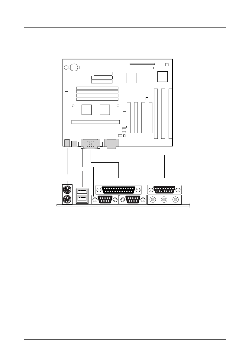
Figure 2. Back Panel I/O Connectors
Product Description
A
DFCHJ
EI
A = PS/2 connector (mouse)
B = Parallel port connector
C = MIDI/game port connector
D = PS/2 connector (keyboard)
E = USB connectors
A26361-D1005-Z120-2-7619
B
G
OM05676
F = Serial port 1 connector
G = Serial port 2 connector
H = Audio line out jack
I = Audio line in jack
J = Audio mic in jack
3
Page 12

Product Description
PCI/IDE Peripheral Interface
The motherboard has a high-speed, 32-bit PCI/IDE interface that supports the
following:
• Up to four PCI/IDE hard drives on the PCI bus
• PIO Mode 3 and Mode 4 hard drives
• Logical block addressing (LBA) of hard drives larger than 528 MB
• Extended Cylinder Head Sector (ECHS) translation modes
• ATAPI devices (such as CD-ROMs)
I/O Features
The I/O controller integrates the functions for the serial ports, parallel port, diskette
drive, and keyboard. This component provides:
• Multimode bidirectional parallel port:
− Standard mode: Centronics-compatible operation
− High-speed mode: Support for enhanced capabilities port (ECP) and
enhanced parallel port (EPP)
• Two RS-232C NS16C450/550-compatible 9-pin serial ports
• Integrated real-time clock with an accuracy of ±13 minutes/year at 25 °C
and 5 V
• Integrated 8042-compatible keyboard controller
• Flexible IRQ and DMA mapping to support Windows 95
• Support for an IrDA or Consumer IR compatible infrared interface. The
infrared interface supports data transfer rates of up to 115 K baud with either
half- or full-duplex operation
• Industry standard diskette drive controller that supports 720 KB, 1.44 MB, and
2.88 MB 3.5-inch drives (at 135 tracks per inch); and 360 KB and 1.2 MB
5.25-inch drives
4
A26361-D1005-Z120-2-7619
Page 13

Product Description
BIOS Features
The BIOS, from American Megatrends, Inc. (AMI), provides ISA and PCI
compatibility. The BIOS is contained in a Flash memory device soldered to the
motherboard. The BIOS provides the POST, the Setup program, a PCI and IDE
auto-configuration utility, and BIOS recovery code.
PCI Auto-configuration
The PCI auto-configuration utility works in conjunction with the Setup program to
support using PCI add-in cards in the computer. When you turn on the power after
installing a PCI card, the BIOS automatically configures interrupts, DMA channels,
and I/O space. Since PCI add-in cards use the same interrupt resources as ISA
add-in cards, you must specify the interrupts used by ISA cards in the Setup
program. The PCI auto-configuration program complies with version 2.1 of the PCI
BIOS specification.
IDE Auto-configuration
The motherboard automatically detects installed IDE devices and configures them
for operation.
ISA Plug and Play Capability
The motherboard provides auto-configuration of Plug and Play ISA cards and
resource management for legacy (non Plug and Play) ISA cards when used with
the ISA Configuration Utility (ICU) or a Plug and Play compatible operating system
like Windows 95. To obtain the ICU, contact your computer supplier.
Security Features
The BIOS provides a password option that you can enable through the Setup
program (refer to
A26361-D1005-Z120-2-7619
Using the BIOS Setup Program
).
5
Page 14

Product Description
BIOS Upgrades
Because the BIOS is stored in a Flash memory device, you can upgrade the BIOS
without having to disassemble the computer. The upgrade can be done with a
utility stored on a diskette or hard disk or run over a network. To upgrade the
BIOS, refer to Upgrade the BIOS.
Expansion Slots
The motherboard has two dedicated 16-bit ISA/AT-compatible and three dedicated
PCI-compatible expansion slots. Another expansion slot is a combination slot that
can be used for either a PCI or an ISA card. This allows you to install a maximum
of six add-in cards.
Real-time Clock and CMOS RAM
The I/O controller provides a real-time clock and CMOS RAM. You can set the
time for the clock and the CMOS values by using the Setup program described in
Using the BIOS SETUP Program.
Battery
A battery on the motherboard keeps the clock and values in CMOS RAM current
when your computer is turned off. To replace the battery, see Installing and
configuring motherboard options.
Speaker
An optional speaker is mounted on the motherboard. The speaker provides
audible error code information (beep codes) during the POST if the BIOS cannot
use the video interface. For beep code descriptions, see Error and Information
Messages.
6
A26361-D1005-Z120-2-7619
Page 15

Product Description
The board also has a connector for an optional offboard speaker. To
✏
install an offboard speaker, remove the jumper that enables the onboard
speaker (refer to
Technical Reference
).
Fan Connectors
The motherboard has connectors for two fans. For the locations and pinouts of the
fan connectors, see
Technical Reference
.
USB Interface Support
The USB ports permit the direct connection of two USB peripherals without an
external hub. If more devices are required, an external hub can be connected to
either of the built-in ports. The motherboard supports the standard universal host
controller interface (UHCI) and uses standard software drivers that are UHCIcompatible.
Features of the USB include:
Support for self-identifying, hot-pluggable peripherals
•
Automatic device configuration
•
Support for isochronous and asynchronous transfers over the same set of
•
wires
Support for up to 127 physical devices
•
Bandwidth and low latencies appropriate for telephony, audio, and other
•
applications
Error handling and fault recovery built into protocol
•
A26361-D1005-Z120-2-7619
7
Page 16

Product Description
Audio Subsystem
The onboard audio subsystem is based on the Yamaha OPL family of single-chip
audio controllers (YM 715). The audio subsystem provides the digital audio and
analog mixing functions needed for recording and playing sound on personal
computers. The subsystem features:
• Line and microphone level inputs
• MIDI/Game port
• 3-D enhanced stereo
• Full digital control of all mixer and volume control functions
• Full duplex operation
• Sound Blaster Pro, Windows Sound System, Roland MPU-401, AdLib, and
Multimedia PC Level 2 (MPCII) compatibility
• Onboard Yamaha YM 704 wavetable synthesizer (optional)
• Wavetable upgrade connector
• CD-ROM audio connector
• Telephony connectors
Hardware Monitor Option
For future purpose.
8
A26361-D1005-Z120-2-7619
Page 17

Using the BIOS Setup Program
This chapter explains how to use the BIOS Setup program. You can use the Setup
program to change the computer's configuration information and boot-up
sequence.
Setup information is stored in CMOS random access memory (RAM) and is
backed up by a battery on the motherboard when power to the computer is off.
Please note that the BIOS delivery status does not always match the specified
default values (see
Load Setup Defaults
Overview of the BIOS Setup Program
To enter the Setup program, turn the computer on and press <F1> when you see
the message:
Press <F1> Key if you want to run SETUP.
You have about five seconds to press <F1> before the boot process continues.
For reference purposes, you should write down the current Setup
✏
When you enter the Setup program, you will see the Main screen. Listed along the
top of the display are three other screens: Advanced, Security, and Exit.
settings. When you make changes to the settings, update this record.
).
Select a screen by pressing the left <←> or right <→> arrow keys.
Use the up <↑> or down <↓> arrow keys to select items within a screen. Use the
<Enter> key to select an item you want to change. For some items, pressing
<Enter> brings up a subscreen. After you have selected an item, use the arrow
keys to change the setting.
Table 1 provides an overview of function keys in the Setup program. Table 2
provides an overview of the menu screens and subscreens in the Setup program.
A26361-D1005-Z120-2-7619
9
Page 18

Using the BIOS Setup Program
Table 1. Overview of the Setup Function Keys
Setup Key Description
<F1> Brings up a help screen for the current item
<Esc> Backs up to the previous screen
In the Main, Advanced, Security, or Exit screen allows you to
exit while discarding changes (see page 39)
<Enter> Selects the current item or option
<↑> Selects the previous item or option
<↓> Selects the next item or option
<←> <→> In the Main, Advanced, Security, or Exit menu screens, changes
the menu screen
<F5> Loads Setup defaults (see page 39)
<F6> Discards current changes (see page 39)
<F10> Exits while saving changes (see page 39)
Table 2. Overview of the Setup Screens
Setup Screen This Screen is Used To
Main Configure basic features such as time, date,
floppy drives, and hard drives
Advanced Configure advanced features such as peripheral
configuration, audio configuration, and advanced
chipset configuration
Security Set passwords
Exit Save or discard changes
Floppy Options Configure a floppy drive
Primary/Secondary IDE
Master/Slave Configuration
Boot Options Configure how the computer boots up
10
Configure IDE devices
A26361-D1005-Z120-2-7619
Page 19

Using the BIOS Setup Program
Setup Screen This Screen is Used To
Peripheral Configuration Configure the serial ports, the parallel port, and
the hard disk drive interfaces
Advanced Chipset
Configuration
Setup Subscreen This Subscreen is Used To
Power Management
Configuration
Plug and Play
Configuration
Event Logging
Configuration
Single Bit ECC Events Report about logged events
Multiple Bit ECC Events Report about logged events
Parity Error Events Report about logged events
Pre-Boot Events Report about logged events
Configure the memory and data buses
Configure the computer's power management
options
Configure the computer's Plug and Play
capabilities
Configure the computer's event logging functions
Main Screen
This section describes the options in the Main screen. If you select some options
from the main screen (for example, Primary IDE Master), the Setup program
displays a subscreen for the selected option.
System Date
Specifies the current date. Select the month from a pop-up menu and type the
date and year.
System Time
Specifies the current time.
A26361-D1005-Z120-2-7619
11
Page 20

Using the BIOS Setup Program
Floppy Options
When selected, this displays the Floppy Options subscreen.
Primary IDE Master
Reports if an IDE device is connected to the Primary IDE Master interface. When
selected, this brings up the Primary IDE Master Configuration subscreen.
Primary IDE Slave
Reports if an IDE device is connected to the Primary IDE Slave interface. When
selected, this brings up the Primary IDE Slave Configuration subscreen.
Secondary IDE Master
Reports if an IDE device is connected to the Secondary IDE Master interface.
When selected, this brings up the Secondary IDE Master Configuration subscreen.
Secondary IDE Slave
Reports if an IDE device is connected to the Secondary IDE Slave interface. When
selected, this brings up the Secondary IDE Slave Configuration subscreen.
Language
Specifies the language of the text strings used in the Setup program and the
BIOS. The options are any installed languages.
Boot Options
When selected, this brings up the Boot Options subscreen.
Video Mode
Reports the video mode. There are no options.
Mouse
Reports if a PS/2 mouse is installed. There are no options.
12
A26361-D1005-Z120-2-7619
Page 21

Using the BIOS Setup Program
Base Memory
Reports the amount of base memory. There are no options.
Extended Memory
Reports the amount of extended memory. There are no options.
BIOS Version
Reports the BIOS version. There are no options.
Floppy Options Subscreen
Floppy A:
Reports if a floppy drive is connected to the system. There are no options.
Floppy B:
Reports if a second floppy drive is connected to the system. There are no options.
Floppy A: Type
Specifies the physical size and capacity of the floppy drive. The options are:
Disabled
•
360 KB, 5.25-inch
•
1.2 MB, 5.25-inch
•
720 KB, 3.5-inch
•
•
1.44/1.25 MB, 3.5-inch (default)
2.88 MB, 3.5-inch
•
A26361-D1005-Z120-2-7619
13
Page 22

Using the BIOS Setup Program
Floppy B: Type
Specifies the physical size and capacity of the floppy drive. The options are:
•
Disabled (default)
• 360 KB, 5.25-inch
• 1.2 MB, 5.25-inch
• 720 KB, 3.5-inch
• 1.44/1.25 MB, 3.5-inch
• 2.88 MB, 3.5-inch
Floppy Access
The BIOS displays this item only if the motherboard supports changing the
read/write or read-only access for floppy drives. The following options change the
access for all attached floppy drives:
•
Read/Write (default)
• Read Only
Primary/Secondary IDE Master/Slave Configuration Subscreens
There are four subscreens used to enable IDE devices (e.g., hard disks):
• Primary IDE Master
• Primary IDE Slave
• Secondary IDE Master
• Secondary IDE Slave
Each of these subscreens contains the following eight fields:
14
A26361-D1005-Z120-2-7619
Page 23

Using the BIOS Setup Program
IDE Device Configuration
Used to manually configure or autoconfigure the attached IDE device. The options
are:
•
Auto Configured (default)
User Definable
•
Disabled
•
If you select User Definable, the Cylinders, Heads, Sectors items can be specified.
If you select Disabled, the BIOS will not scan for a drive on that interface.
Cylinders
If IDE Device Configuration is set to User Definable, type the correct number of
cylinders for the installed hard disk. If IDE Device Configuration is set to Auto
Configured, this field reports the number of cylinders for the hard disk.
Heads
If IDE Device Configuration is set to User Definable, type the correct number of
heads for the installed hard disk. If IDE Device Configuration is set to Auto
Configured, this field reports the number of heads for the hard disk.
Sectors
If IDE Device Configuration is set to User Definable, type the correct number of
sectors for the installed hard disk. If IDE Device Configuration is set to Auto
Configured, this field reports the number of sectors for the hard disk.
Maximum Capacity
Reports the maximum capacity of the hard disk. Capacity is calculated from the
number of cylinders, heads, and sectors. There are no options.
A26361-D1005-Z120-2-7619
15
Page 24

Using the BIOS Setup Program
IDE Translation Mode
Do not change the IDE translation mode after the IDE device has been
formatted. Changing the option could corrupt data.
!
Specifies the IDE translation mode. The options are:
• Standard CHS (standard cylinder head sector: fewer than 1024 cylinders)
• Logical Block
• Extended CHS (extended cylinder head sector: more than 1024 cylinders)
• Auto Detected (default) (BIOS detects IDE translation mode
Multiple Sector Setting
Sets the number of sectors transferred by an IDE drive per interrupt generated.
The options are:
• Disabled
• 4 Sectors/Block
• 8 Sectors/Block
• Auto Detected (default)
Check the specifications for the hard disk to determine which setting provides
optimum performance.
Fast Programmed I/O Modes
Sets how fast transfers on the IDE interface occur. The options are:
• Disabled
• Auto Detected (default)
If this option is set to Disabled, transfers occur at a less than optimized speed. If it
is set to Auto Detected, transfers occur at maximum speed.
Boot Options Subscreen
This section describes the options in the Boot Options subscreen.
16
A26361-D1005-Z120-2-7619
Page 25

Using the BIOS Setup Program
First Boot Device
Sets which drive the computer checks first to find an operating system to boot
from. The options are:
Disabled
•
•
Floppy (default)
Hard Disk
•
CD-ROM
•
Network
•
Second Boot Device
Sets which drive the computer checks second to find an operating system to boot
from. The options are:
Disabled
Floppy
Hard Disk (default)
Network
Third Boot Device
Sets which drive the computer checks third to find an operating system to boot
from. The options are:
•
Disabled (default)
Floppy
•
Hard Disk
•
Network
•
A26361-D1005-Z120-2-7619
17
Page 26

Using the BIOS Setup Program
Fourth Boot Device
Sets which drive the computer checks fourth to find an operating system to boot
from. The options are:
•
Disabled (default)
• Floppy
• Hard Disk
• Network
System Cache
Enables or disables both primary and secondary cache memory. The options are:
• Disabled
•
Enabled (default)
Boot Speed
Sets the speed at which the motherboard operates at boot-up. The options are:
• Deturbo
•
Turbo (default)
If turbo boot speed is enabled, the motherboard operates at full speed. If deturbo
boot speed is enabled, the motherboard operates at a slower speed needed to
support some legacy add-in cards.
Num Lock
Sets the Num Lock feature on your keyboard at boot-up. The options are:
•
Off (default)
• On
18
A26361-D1005-Z120-2-7619
Page 27

Using the BIOS Setup Program
Setup Prompt
This option does not affect your ability to access the Setup program. It
only toggles the prompt.
Turns on (or off) the "Press <F1> Key if you want to run Setup” prompt during the
power-up sequence. The options are:
•
Enabled (default)
Disable
•
Hard Disk Pre-Delay
Sets the hard disk drive pre-delay. The options are:
•
Disabled (default)
3 Seconds
•
6 Seconds
•
9 Seconds
•
12 Seconds
•
15 Seconds
•
21 Seconds
•
30 Seconds
•
When this option is enabled, the BIOS waits the specified time before accessing
the first hard drive. If your computer contains a hard drive, and you don't see the
drive type displayed during boot-up, the hard drive might need more time before it
can communicate with the controller. Setting a pre-delay provides the additional
time for the hard drive to initialize.
Typematic Rate Programming
Sets the typematic rates. The options are:
•
Default (default)
Override
•
Selecting Override enables the Typematic Rate Delay and Typematic Rate fields.
A26361-D1005-Z120-2-7619
19
Page 28

Using the BIOS Setup Program
Typematic Rate Delay
Sets the delay time (in milliseconds) for the key-repeat function to start when you
hold down a key on the keyboard. The options are:
•
250 msec (default)
• 500 msec
• 750 msec
• 1000 msec
If the Typematic Rate Programming field is set to Default, this option will not
appear.
Typematic Rate
Sets the speed (in characters per second) at which characters repeat when you
hold down a key on the keyboard. The higher the number, the faster the
characters repeat. The options are:
•
6 char/sec (default)
• 8 char/sec
• 10 char/sec
• 12 char/sec
• 15 char/sec
• 20 char/sec
• 24 char/sec
• 30 char/sec
If the Typematic Rate Programming field is set to Default, this option will not
appear.
Scan User Flash Area
Enables or disables scanning of user Flash area for ROMs. The options are:
•
Disabled (default)
• Enabled (scan occurs during POST)
20
A26361-D1005-Z120-2-7619
Page 29

Using the BIOS Setup Program
Power-On COM1 Ring
Enables the computer to power on when a telephony device operating on COM1
receives a call. The options are:
•
Disabled (default)
Enabled
•
Advanced Screen
This section describes the Setup options in the Advanced menu screen. If you
select some options from the Advanced screen (for example, Peripheral
Configuration), Setup displays a subscreen for the selected option. Subscreens
are described in the sections following the description of the Advanced screen
options.
Processor Type
Reports the processor type. There are no options.
Processor Speed
Reports the processor clock speed. There are no options.
Cache Size
Reports the size of second-level cache memory. There are no options.
Peripheral Configuration
When selected, this displays the Peripheral Configuration subscreen.
Advanced Chipset Configuration
When selected, this displays the Advanced Chipset Configuration subscreen.
Power Management Configuration
When selected, this displays the Power Management Configuration subscreen.
A26361-D1005-Z120-2-7619
21
Page 30

Using the BIOS Setup Program
Plug and Play Configuration
When selected, this displays the Plug and Play Configuration subscreen.
Event Logging Configuration
When selected, this displays the Event Logging Configuration subscreen.
Peripheral Configuration Subscreen
This section describes the Setup options in the Peripheral Configuration
subscreen.
When Auto Configured is selected for Primary PCI IDE Interface, Secondary PCI
IDE Interface, Floppy Interface, Serial Port 1 Interface, Serial Port 2 Interface,
Serial Port 2 IR Mode, or Parallel Port Interface, the computer automatically
configures that peripheral during power up. Reported settings for these options
reflect the current state of the computer.
Primary PCI IDE Interface
Use to disable or automatically configure the primary PCI IDE interface. The
options are:
• Disabled
•
Auto Configured (default)
When Auto Configured is selected, the Primary PCI IDE Interface is automatically
configured during power up.
Secondary PCI IDE Interface
Use to disable or automatically configure the secondary PCI IDE interface. The
options are:
• Disabled
•
Auto Configured (default)
When Auto Configured is selected, the Secondary PCI IDE Interface is
automatically configured during power up.
22
A26361-D1005-Z120-2-7619
Page 31

Using the BIOS Setup Program
Floppy Interface
Enables or disables the floppy drive interface. The options are:
Disabled
•
Enabled
•
•
Auto Configured (default)
When Auto Configured is selected, the floppy interface is automatically configured
during power up.
Serial Port 1 Interface
Selects the COM port, I/O address, and IRQ of serial port 1. The options are:
Disabled
•
COM1 3F8 IRQ4
•
COM2 2F8 IRQ3
•
COM3 3E8 IRQ4
•
COM4 2E8 IRQ3
•
COM1 3F8 IRQ3
•
COM2 2F8 IRQ4
•
COM3 3E8 IRQ3
•
COM4 2E8 IRQ4
•
•
Auto Configured (default)
When Auto Configured is selected, the Setup program assigns the first free COM
port (normally COM1, 3F8, IRQ4) as the serial port 1 address and IRQ.
A26361-D1005-Z120-2-7619
23
Page 32

Using the BIOS Setup Program
Serial Port 2 Interface
If either serial port address is set, the address it is set to will not appear in
the options dialog box of the other serial port. If an
mach64
appear in the options dialog box of either serial port.
Selects the COM port, I/O address, and IRQ of serial port 2. The options are:
video controller is active, the COM4, 2E8, IRQ3 address will not
ATI mach32
or an
• Disabled
• COM1 3F8 IRQ4
• COM2 2F8 IRQ3
• COM3 3E8 IRQ4
• COM4 2E8 IRQ3
• COM1 3F8 IRQ3
• COM2 2F8 IRQ4
• COM3 3E8 IRQ3
• COM4 2E8 IRQ4
•
Auto Configured (default)
ATI
When Auto Configured is selected, the Setup program assigns the first free COM
port (normally COM2, 2F8, IRQ3) as the serial port 2 address and IRQ.
Serial Port 2 IR Mode
Makes Serial Port 2 available to infrared applications. The options are:
•
Disabled (default)
• Enabled
24
A26361-D1005-Z120-2-7619
Page 33

Using the BIOS Setup Program
Parallel Port Interface
Selects the printer port, I/O address, and IRQ of the parallel port. The DMA
assignment for the port will be displayed if the Parallel Port Type is set to ECP.
The options are:
Disabled
•
LPT3 3BC IRQ7
•
LPT1 378 IRQ7
•
LPT2 278 IRQ7
•
LPT3 3BC IRQ5
•
LPT1 378 IRQ5
•
LPT2 278 IRQ5
•
•
Auto Configured (default)
When Auto Configured is selected, the Setup program assigns LPT1, 378, IRQ7
as the parallel port address and IRQ.
Parallel Port Type
Selects the mode for the parallel port. The options are:
•
Compatible (default)
Bi-directional
•
ECP
•
EPP
•
Compatible means the parallel port operates in AT-compatible mode. Bi-directional
means the parallel port operates in bidirectional PS/2-compatible mode. EPP and
ECP mean the parallel port operates high-speed, bidirectionally.
USB Interface
Enables or disables the USB interface. The options are:
Disabled
•
•
Enabled (default)
A26361-D1005-Z120-2-7619
25
Page 34

Using the BIOS Setup Program
Audio Interface
Enables or disables the onboard audio subsystem. The options are:
• Disabled
•
Enabled (default)
Hardware Monitor Interface
Enables or disables the hardware monitor. The options are:
• Disabled
•
Enabled (default)
This option is displayed only if the hardware monitor component is installed on the
motherboard.
Primary PCI IDE Status
Reports if the Primary IDE Interface is enabled or disabled. There are no options.
Secondary PCI IDE Status
Reports if the Secondary IDE Interface is enabled or disabled. There are no
options.
Floppy Status
Reports if the Floppy Interface is enabled or disabled. There are no options.
Serial Port 1 Status
Reports the COM port, I/O address, and IRQ for serial port 1 (COM1). There are
no options.
Serial Port 2 Status
Reports the COM port, I/O address, and IRQ for serial port 2 (COM2). There are
no options.
26
A26361-D1005-Z120-2-7619
Page 35

Using the BIOS Setup Program
Parallel Port Status
Reports the printer port, I/O address, and IRQ for the parallel port. There are no
options.
Advanced Chipset Configuration Subscreen
This section describes the options in the Advanced Chipset Configuration
subscreen.
Base Memory Size
Sets the size of the base memory. The options are:
512 KB
•
•
640 KB (default)
ISA LFB Size
Sets the size of the linear frame buffer. The options are:
•
Disabled (default)
1 MB
•
2 MB
•
4 MB
•
If this option is set to 1 MB, 2MB, or 4MB, the ISA LFB Base Address field
appears.
ISA LFB Base Address
Reports the base address of the LFB. There are no options.
Video Palette Snoop
Controls the ability of a primary PCI graphics controller to share a common palette
with an ISA add-in video card. The options are:
•
Disabled (default)
Enable
•
A26361-D1005-Z120-2-7619
27
Page 36

Using the BIOS Setup Program
ISA VGA Write Combining
Sets the VGA frame buffer address (B000h - BFFFh) to the processor's Write
Combined memory type. The options are:
•
Disabled (default)
• Enable
Latency Timer (PCI Clocks)
Sets the length of time (in PCI clocks) an agent on the PCI bus can hold the bus
when another agent has requested the bus. The options are:
•
Auto Configured (default)
• Valid numbers between 16 and 128 (in multiples of 8)
Memory Error Detection
In the delivery status, this setting is set to ECC. When the default values are being
set (Load Setup Defaults), this value must then be reset to ECC.
Sets the type of memory error detection or correction. The options are:
• Disabled (default)
•
ECC (factory setting)
• Parity
This option only appears if the memory installed on the motherboard supports
error detection.
Bank 0
Reports the size and type of memory installed in bank 0. There are no options.
Bank 1
Reports the size and type of memory installed in bank 1. There are no options.
28
A26361-D1005-Z120-2-7619
Page 37

Using the BIOS Setup Program
Power Management Configuration Subscreen
This section describes the options in the Power Management Configuration
subscreen.
Advanced Power Management
Enables or disables the advanced power management (APM) support in the
computer's BIOS. The options are:
Disabled
•
•
Enabled (default)
APM features require an APM-capable operating system. If this option is set to
Disabled, only the Auto Start On AC Loss option will appear. If this option is set to
Enabled, all the following options will appear.
IDE Drive Power Down
Sets any IDE drives to spin down when the computer goes into power-managed
mode. The options are:
Disabled
•
•
Enabled (default)
VESA Video Power Down
Sets the command issued to your VESA-compliant graphics add-in card when the
computer enters power-managed mode. The options are:
Disabled (the monitor is not under power management)
•
Standby (minimal power reduction)
•
Suspend (significant power reduction)
•
•
Sleep (default)
Inactivity Timer
Sets how long (in minutes) the computer must be inactive before it enters powermanaged mode. The range is 0-255 minutes. The default is 10 minutes.
A26361-D1005-Z120-2-7619
(maximum power reduction)
29
Page 38

Using the BIOS Setup Program
Hot Key
Sets the hot key for power-managed mode. Press the hot key while holding down
the <Ctrl> and <Alt> keys to enter power-managed mode. All alphabetic keys are
valid entries for this field.
Auto Start On AC Loss
Specifies whether the power supply should resume after AC power interruption.
The options are:
• Disabled
•
Enabled (default)
Plug and Play Configuration Subscreen
This section describes the options in the Plug and Play Configuration subscreen.
Configuration Mode
In the delivery status, this setting is set to Use BIOS Setup . When the default values
are being set (Load Setup Defaults), this value must then be reset to Use BIOS
Setup.
Sets how the BIOS gets information about non-Plug and Play ISA add-in cards.
The options are:
• Use PnP OS (default)
•
Use BIOS Setup (factory setting)
If Use BIOS Setup is selected, specify the IRQ for each non-Plug and Play ISA
add-in card you install on the motherboard (see page 32, IRQ 3, 4, 5, 7, 9, 10, 11,
14, 15).
If Use PnP OS is selected, the BIOS uses run-time software to prevent conflicts
between Plug and Play and non-Plug and Play add-in cards. If Use PnP OS is
selected, PnP OS is the only option visible in the subscreen.
PnP OS
Enables the computer to boot with an operating system capable of managing Plug
and Play add-in cards. The options are:
30
A26361-D1005-Z120-2-7619
Page 39

Using the BIOS Setup Program
Disabled
•
Other PnP OS
•
•
Windows 95 (default)
This field will only be visible if the Configuration Mode field is set to Use PnP OS.
ISA Shared Memory Size
Enables you to specify a range of memory addresses that will be directed to the
ISA bus rather than to onboard memory. The options are:
•
Disabled (default)
16 KB
•
32 KB
•
48 KB
•
64 KB
•
80 KB
•
96 KB
•
If this field is set to Disabled, the ISA Shared Memory Base Address field
(described below) will not appear.
This field should be enabled only when you are using a non-Plug and Play ISA
add-in card (legacy card) that requires non-ROM memory space. For example,
video capture cards that have video buffer memory.
By default, allocation of upper memory is as follows: memory from C0000hC7FFFh is automatically shadowed. (This memory range is typically reserved for
video BIOS.) Memory from C8000h-DFFFFh is initially unshadowed. The BIOS
scans this range for any ISA add-in cards that may be present and notes their
location and size. The BIOS will then automatically configure the PCI and Plug and
Play devices, shadowing the ROM requirements (other than video) into the area
above E0000h until that area is full. It will then assign additional PCI and Plug and
Play add-in cards to the area between C8000h and DFFFFh. If an ISA legacy card
has non-ROM memory requirements, the autoconfigure routine may write into an
area that is needed by the ISA add-in card. The ISA Shared Memory Size
parameter signifies to the autoconfigure routine that this block of memory is
reserved and should not be shadowed.
Shadowing copies a block of memory from an add-in card's ROM to the same
address in computer DRAM memory. This improves computer performance.
A26361-D1005-Z120-2-7619
31
Page 40

Using the BIOS Setup Program
ISA Shared Memory Base Address
Sets the base address for the ISA shared memory. The options are:
•
C8000h (default)
• CC000h
• D0000h
• D4000h
• D8000h
• DC000h
This setting could affect the ISA Shared Memory Size field. The value entered in
the ISA Shared Memory Size field cannot extend to the E0000h address. For
example, if a size of 64 KB were selected, options D4000h, D8000h, and DC000h
would not appear.
If the ISA Shared Memory Size field is disabled, this field will not appear.
IRQ 3, 4, 5, 7, 9, 10, 11, 14, 15
Sets the status of the IRQ. The options are:
•
Available (default)
• Used By ISA Card
The PCI auto-configuration code looks here to see if these IRQs are available for
PCI add-in cards. If an IRQ is available, the PCI auto-configuration code can
assign the IRQ to be used by the computer. If your computer has an ISA add-in
card, select Used By ISA Card for one of these IRQs.
IRQs 5, 9, 10, and 11 are the default user available IRQs. Depending on
the configuration of your computer, other IRQs could be listed. If you
have disabled the parallel port or either of the serial ports, more IRQs will
be available. Refer to Technical Reference ("Motherboard Resources",
"Interrupts") for information on reserved and available IRQs.
If an ICU diskette was supplied with your computer, you can use the ICU
(ISA Configuration Utility) utility to check how the interrupts are assigned.
Boot your computer with the ICU diskette inserted and follow the
instructions on the screen.
Event Logging Configuration Subscreen
This section describes the options in the Event Logging Configuration subscreen.
32
A26361-D1005-Z120-2-7619
Page 41

Using the BIOS Setup Program
Event Log Capacity
Reports whether or not the log is full. There are no options.
Event Log Count Granularity
Reports the number of log events that must occur before the event log is updated.
There are no options.
Event Time Granularity
Reports the amount of time (in minutes) that must pass before the event log is
updated. There are no options.
Event Log Control
Enables or disables event logging. The options are:
•
All Events Enabled (default)
ECC Events Disabled
•
All Events Disable
•
Clear Event Log
Clears the event log on the next pass through POST. The options are:
•
Keep (default)
On Next Boot
If set to On Next Boot, this option reverts to the default on the next pass
through POST.
Mark Existing Events as Read
Marks all events already in the log as having been not read (Do Not Mark) or read
(Mark). The options are:
•
Do Not Mark (default)
Mark
•
A26361-D1005-Z120-2-7619
33
Page 42

Using the BIOS Setup Program
Single Bit ECC Events
When selected, this displays the Single Bit ECC Events subscreen.
Multiple Bit ECC Events
When selected, this displays the Multiple Bit ECC Events subscreen.
Parity Error Events
When selected, this displays the Parity Error Events subscreen.
Pre-Boot Events
When selected, this displays the Pre-Boot Events subscreen.
Single Bit ECC Events Subscreen
If Clear Event Log is set to On Next Boot (see page 33), the following fields report
information for the last single-bit ECC error to occur since the last pass through
POST.
Date of Last Occurrence
Reports the date when the last single-bit ECC error occurred. There are no
options.
Time of Last Occurrence
Reports the time when the last single-bit ECC error occurred. There are no
options.
Total Count of Events/Errors
Reports the total number of single-bit ECC errors in the log. There are no
options.
Memory Bank with Errors
Reports the memory bank that contained the last single-bit ECC error. There
are no options.
34
A26361-D1005-Z120-2-7619
Page 43

Using the BIOS Setup Program
Multiple Bit ECC Events Subscreen
If Clear Event Log is set to On Next Boot (see page 33), the following fields report
information for the last multiple-bit ECC error to occur since the last pass through
POST.
Date of Last Occurrence
Reports the date when the last multiple-bit ECC error occurred. There are no
options.
Time of Last Occurrence
Reports the time when the last multiple-bit ECC error occurred. There are no
options.
Total Count of Events/Errors
Reports the total number of multiple-bit ECC errors in the log. There are no
options.
Memory Bank with Errors
Reports the memory bank that contained the last multiple-bit ECC error. There
are no options.
Parity Error Events Subscreen
If Clear Event Log is set to On Next Boot (see page 33), the following fields report
information for the last parity error to occur since the last pass through POST.
Date of Last Occurrence
Reports the date when the last parity error occurred. There are no options.
Time of Last Occurrence
Reports the time when the last parity error occurred. There are no options.
A26361-D1005-Z120-2-7619
35
Page 44

Using the BIOS Setup Program
Total Count of Events/Errors
Reports the total number of parity errors in the log. There are no options.
Memory Bank with Errors
Reports the memory bank that contained the last parity error. There are no
options.
Pre-Boot Events Subscreen
If Clear Event Log is set to On Next Boot (see page 33), the following fields report
information for the last pre-boot event to occur since the last pass through POST.
Date of Last Occurrence
Reports the date when the last pre-boot event occurred. There are no options.
Time of Last Occurrence
Reports the time when the last pre-boot event occurred. There are no options.
Total Count of Events/Errors
Reports the total number of pre-boot events in the log. There are no options.
Security Screen
The Security screen enables you to set passwords for two access modes:
administrative and user.
Administrative mode allows the administrative user to view and change all Setup
program options while user mode limits access to Setup program options. User
mode access to the Setup program is set in administrative mode by the Enter
Password and User Privilege Level options. Setting a user privilege level enables
system administrators to restrict who can view or change options in the Setup
program. If you set the administrative password only, you can gain user mode
access to the Setup program by pressing the <Enter> key at the password prompt.
To restrict who can boot the computer, set the user password. The computer will
prompt the user for this password before booting. If you set the administrative
36
A26361-D1005-Z120-2-7619
Page 45

Using the BIOS Setup Program
password only, the computer will boot without prompting the user for a password.
If both passwords are set, a user can enter either the administrative or user
password to boot the computer.
The following table shows how the passwords work together.
Password
Set
Neither Can change all
Administrative
Mode User Mode
Can change all options None
Password
Needed to Boot
options
Administrative only
Can change all
options
Access controlled by user
privilege level setting
None
User only N/A Can change all options User
Both Can change all
options
Access controlled by user
privilege level setting
Administra-tive or
user
Descriptions of the options in the Security screen follow.
User Password
Reports if there is a user password set. There are no options.
Administrative Password
Reports if there is an administrative password set. There are no options.
Enter Password
Sets the user password. The password can be up to seven alphanumeric
characters.
Set Administrative Password
Sets the administrative password. The password can be up to seven alphanumeric
characters.
A26361-D1005-Z120-2-7619
37
Page 46

Using the BIOS Setup Program
User Privilege Level
This option appears when an administrative password is set. User Privilege Level
sets the level of user mode access to the Setup program. This option can only be
set in administrative mode. The options are:
•
Limited Access (default)
• No Access
• View Only
• Full Access
Privilege
Level User Mode Access to Setup Program
Limited
Access
No Access Cannot access the Setup program
View Only Can access the Setup program and view options, but not change
Full Access Can access the Setup program and change all options except
Clear User Password
This option appears when both an administrative and user password are set.
Press the <Enter> key to clear the user password.
Unattended Start
Controls when the user password is requested. The options are:
Can access the Setup program and change: System Date,
System Time, User Password, Unattended Start, and Security
Hot-Key
them
User Privilege Level and Set Administrative Password
• Enabled
•
Disabled (default)
The user password must be set before you can enable this option. If Enabled is
selected, the computer boots, but the keyboard will be locked until the user
password is entered.
38
A26361-D1005-Z120-2-7619
Page 47

Using the BIOS Setup Program
Security Hot Key (CTRL-ALT-)
Sets a hot key that, when pressed, locks the keyboard until the user password is
entered. The keyboard LEDs flash to indicate that the keyboard is locked. When
you enter the user password, you do not have to press the <Enter> key.
Exit Screen
This section describes how to exit and save changes to the Setup program or exit
and discard changes to the Setup program.
Exit Saving Changes
Exits and saves changes made to the Setup program. You can also press the
<F10> key anywhere in the Setup program to exit and save changes.
Exit Discarding Changes
Exits without saving changes made to the Setup program. This means that any
changes you made to the Setup program are discarded and
also press the <Esc> key in the four main screens to exit the Setup program
without saving changes.
not saved
. You can
Load Setup Defaults
Returns all Setup program options to their defaults. You can also press the <F5>
key anywhere in the Setup program to load the Setup defaults.
When you execute this function, you must reset the values
and
Configuration Mode
This option loads the default Setup values from the ROM table.
Discard Changes
Discards any changes you made during the current Setup session without exiting
the program. You can also press the <F6> key anywhere in the Setup program to
discard any changes to Setup without exiting the program.
This option loads the CMOS RAM values that were present when the computer
was turned on.
A26361-D1005-Z120-2-7619
to those in the delivery status.
Memory Error Detection
39
Page 48

Page 49

Installing and Configuring Motherboard Options
This chapter describes the following:
Jumper locations and functions
•
How to set jumpers for Setup program functions
•
How to install a processor and set jumpers for processor speed
•
How to prepare the motherboard for installation of a boxed Pentium II
•
processor
How to install memory
•
How to replace the battery
•
How to remove the motherboard
•
Before You Begin
If you are installing this motherboard in a chassis, please note the
information provided in the chapter "Safety" in the Operating Manual of
!
the PC.
Always follow the steps in each procedure in the correct order.
Set up a log to record information about your computer such as model, serial
numbers, and installed options. If you need this information, it will be easier to
consult the log than to open up the computer.
We recommend you use an antistatic wrist strap and a conductive foam pad when
working on the motherboard.
A26361-D1005-Z120-2-7619
41
Page 50

Installing and Configuring Motherboard Options
a
r
D
d
WARNINGs
!
The procedures in this chapter assume familiarity with the general terminology
ssociated with personal computers and with the safety practices and
egulatory compliance required for using and modifying electronic equipment.
isconnect the computer from its power source and from any telecom-
munications links, networks, or modems before doing any of the procedures
escribed in this chapter. Failure to disconnect power, telecom-munications
links, networks, or modems before you open the computer or do any procedures
can result in personal injury or equipment damage. Some circuitry on the
motherboard may continue to operate even though the front panel power
button is off.
Electrostatic discharge (ESD) can damage components. Do the
procedures described in this chapter only at an ESD workstation. If such
a station is not available, you can provide some ESD protection by
wearing an antistatic wrist strap and attaching it to a metal part of the
computer chassis.
Jumpers
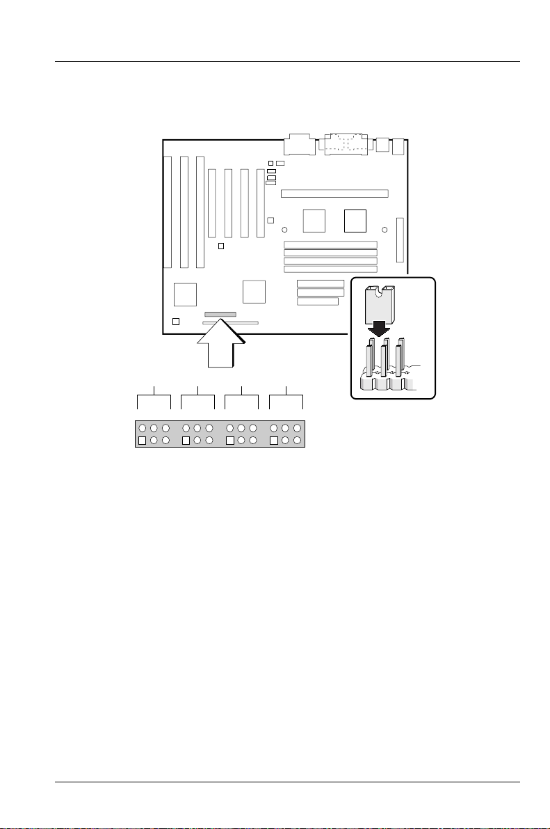
Figure 3 shows the location of the jumper block on the motherboard. The jumpers
have been set correctly at the factory. Normally, the only time you will have to
change a jumper is if you need to do one of the following:
Clear the user or administrator password.
Reset CMOS RAM to the default values.
Disable or enable access to the Setup program.
Configure the motherboard for a different processor speed.
As shown in Figure 3, a jumper is a small plastic-encased conductor that
slips over jumper pins. To change a jumper setting, remove the jumper
from the pins and slide it onto the new pins to obtain the desired setting.
You can use a pair of fine needle nose pliers to remove and install
jumpers.
To avoid bending or breaking pins, use caution when removing or
installing a jumper.
!
42
A26361-D1005-Z120-2-7619
Page 51
Installing and Configuring Motherboard Options
Figure 3. Jumper Block
A B C D
465
465
32
465
3211
465
J9C1
321
321
OM05677
Jumpers for Setup Program Functions
Table 3 shows jumper settings for Setup program functions. Figure 3 shows the
location of the jumper block. For each function, see the step-by-step instructions
that follow. For more information about the Setup program, refer to Using the BIOS
Setup Program.
A26361-D1005-Z120-2-7619
43
Page 52
Installing and Configuring Motherboard Options
Table 3. Jumpers for Setup Program Functions
Function Block Pins Description
Setup Program Access J9C1-D 5-6 Enabled (default)
4-5 Disabled
BIOS Recovery* J9C1-A 5-6 Normal (default)
4-5 Recover
CMOS Clear J9C1-C 5-6 Keep (default)
4-5 Clear
* Refer to Upgrade the BIOS for information on upgrading the BIOS.
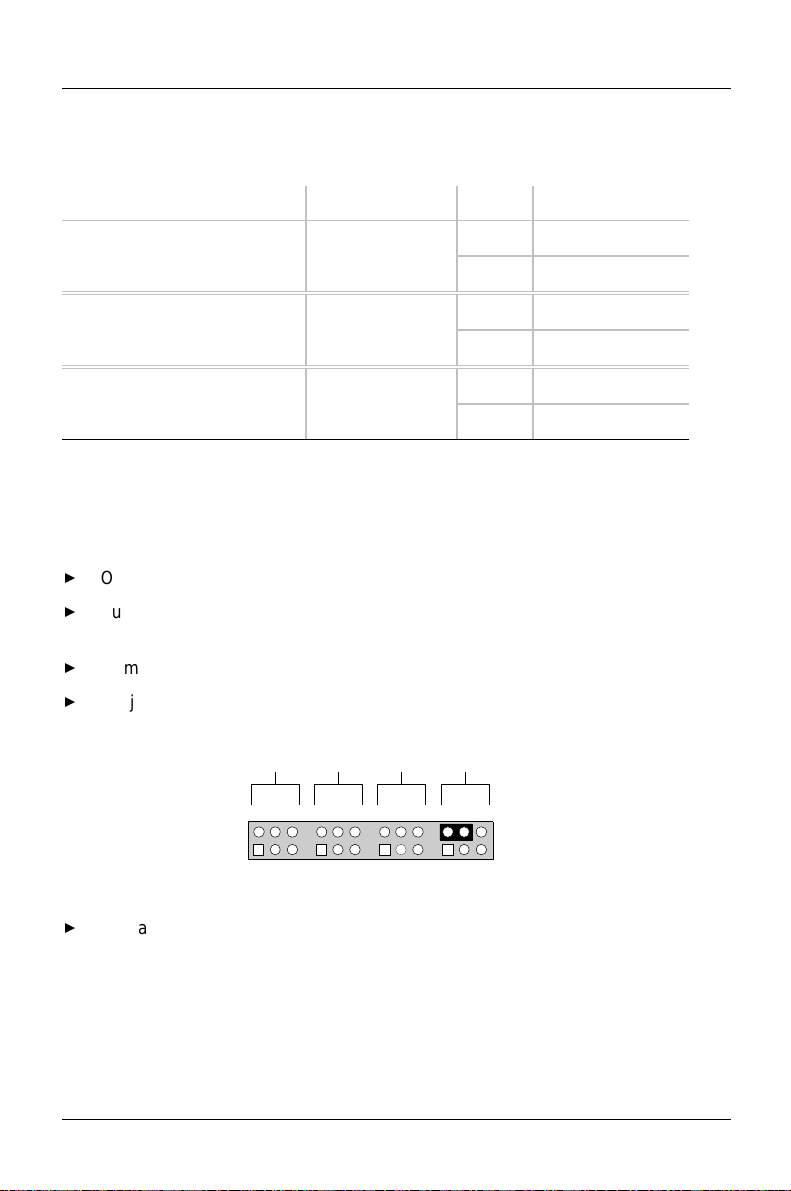
How to Disable Access to the Setup Program
Observe the precautions in "Before You Begin” (see page 41).
Turn off all peripheral devices connected to the computer. Turn off the
computer.
Remove the computer cover.
On jumper block J9C1-D, move the jumper from pins 5-6 to pins 4-5 as shown
below.
A B C D
465
Replace the cover and turn on the computer.
44
465
321
465
321
465
J9C1
321
321
OM05681
A26361-D1005-Z120-2-7619
Page 53
Installing and Configuring Motherboard Options
How to Enable Access to the Setup Program
Observe the precautions in "Before You Begin” (see page 41).
Turn off all peripheral devices connected to the computer. Turn off the
computer.
Remove the computer cover.
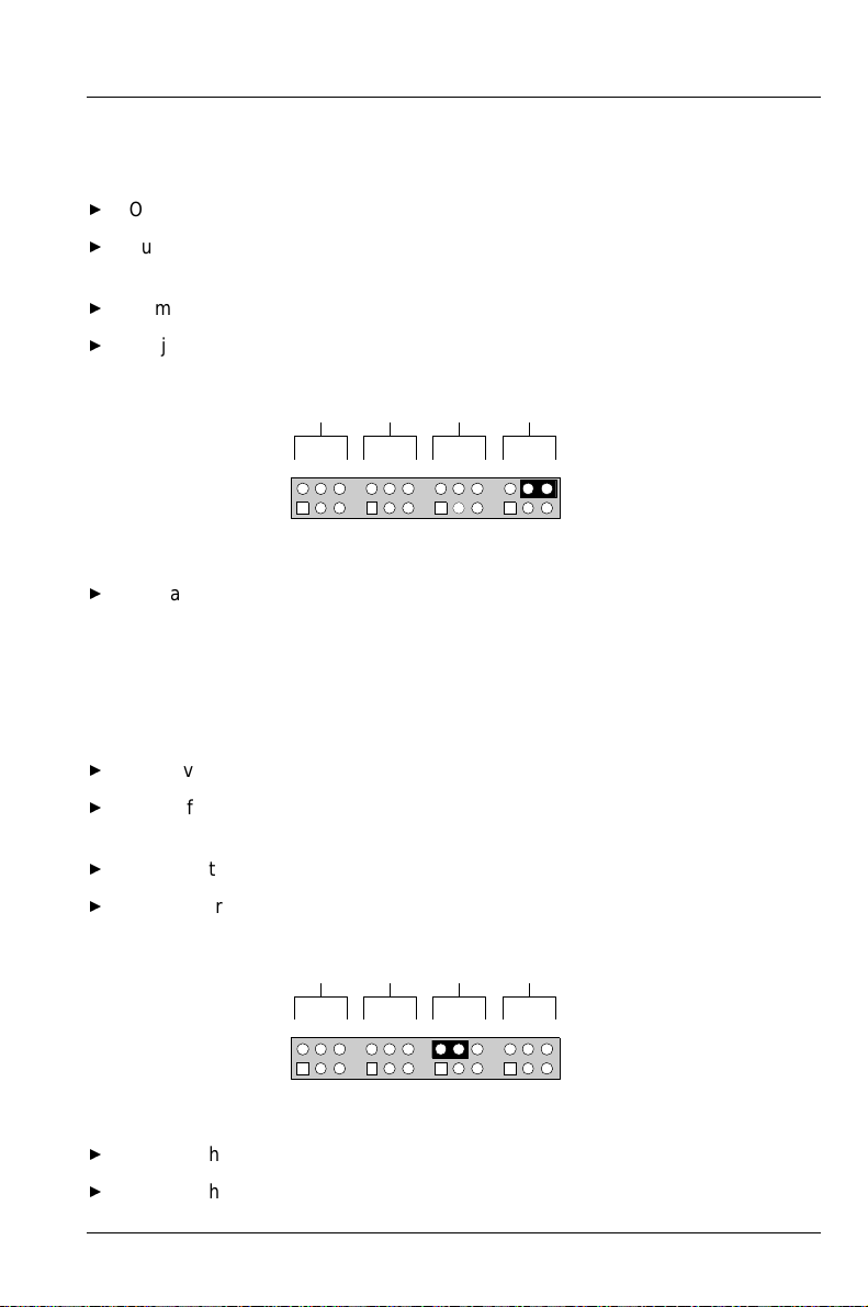
On jumper block J9C1-D, move the jumper from pins 4-5 to pins 5-6 as shown
below.
A B C D
465
Replace the cover and turn on the computer.
465
32
465
3211
465
J9C1
321
321
OM05680
How to Clear CMOS RAM
Normally, you should only have to do this procedure after you upgrade the BIOS.
Observe the precautions in "Before You Begin” (see page 41).
Turn off all peripheral devices connected to the computer. Turn off the
computer.
Remove the computer cover.
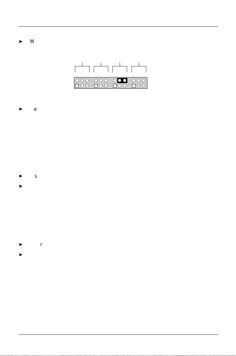
On jumper block J9C1-C, move the jumper from pins 5-6 to pins 4-5 as shown
below.
A B C D
465
465
32
465
3211
465
J9C1
321
321
OM05682
Turn on the computer and allow it to boot.
Turn off the computer.
A26361-D1005-Z120-2-7619
45
Page 54
Installing and Configuring Motherboard Options
Move the jumper back to pins 5-6 to restore normal operation as shown
below.
A B C D
465
Replace the cover and turn on the computer.
465
32
465
3211
465
J9C1
321
321
OM05683
How to Install a Processor
This section describes how to install a processor on the motherboard. The
processor installs in the motherboard's Slot 1 connector shown in Figure 1.
To install a processor, you must:
Install the processor.
Set the processor speed jumpers.
Detailed instructions for each of these procedures follow.
Install the Processor
To install the processor follow these steps:
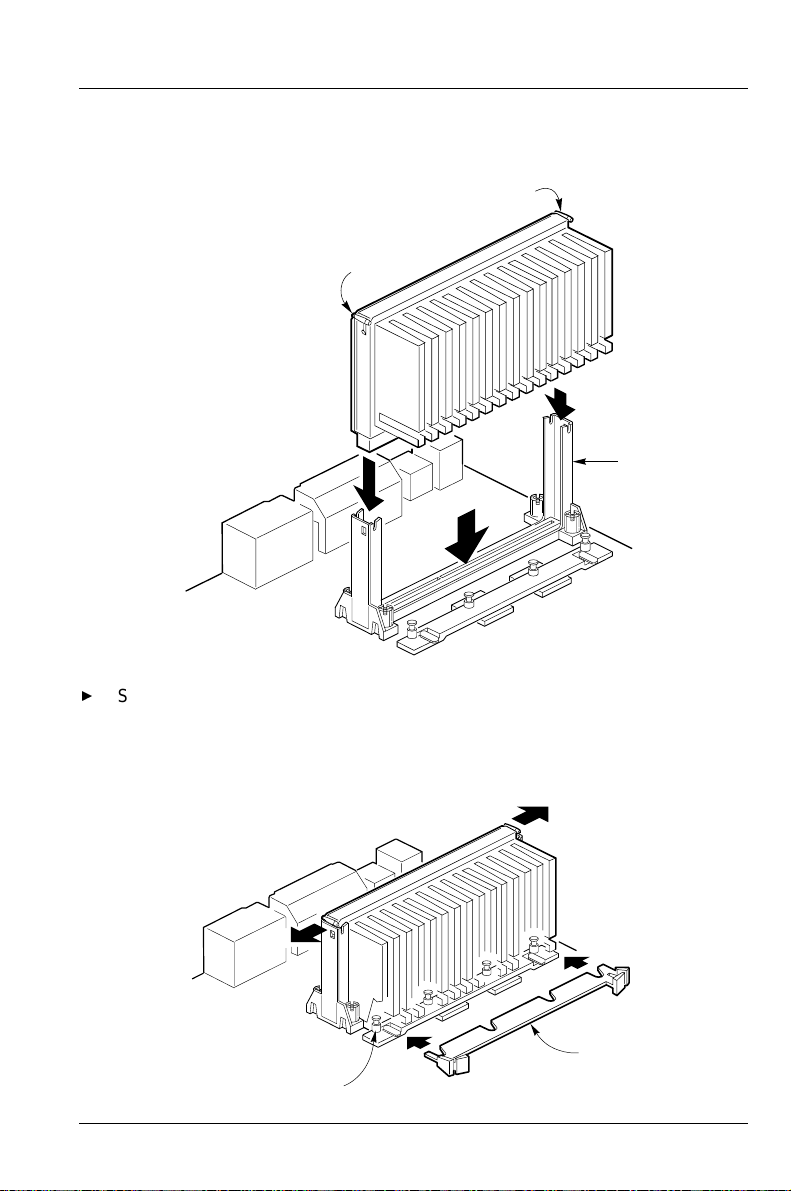
Insert the processor in the retention mechanism (B) as shown in Figure 4.
Press down on the processor until it is firmly seated in the Slot 1 connector
and the latches (A) on the processor lock into place.
46
A26361-D1005-Z120-2-7619
Page 55
Installing and Configuring Motherboard Options
Figure 4. Installing the Processor
A
A
B
OM05751
Slide the top heatsink support bar (A) onto the retaining pins (B) of the
support's base as shown in Figure 5 (not used).
Figure 5. Installing the Heatsink Support Top Bar (not used)
A
B
A26361-D1005-Z120-2-7619
OM05752
47
Page 56

Installing and Configuring Motherboard Options
Remove the Installed Processor
Remove the processor by pressing in on the latches (A) and pulling the
processor straight up (see Figure 4). Place the processor aside.
Set the Processor Speed Jumpers
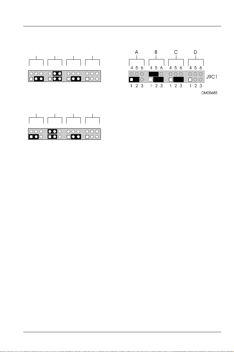
Make sure that motherboard jumpers J9C1-A, J9C1-B, and J9C1-C are set to the
correct value for the speed of the processor. Table 4 lists jumper settings for
233 MHz, 266 Mhz and 300 MHz processors. Figure 3 shows the location of the
jumper block.
Table 4. Jumpers for Processor Speed (MHz)
Processor Host Bus Block J9C1
Speed* Speed A B C
233 MHz 66 2-3 2-3,
5-6
266 MHz 66 1-2 1-2,
4-5
300 MHz 66 1-2 2-3,
4-5
* See the processor's documentation for the correct speed (Mhz).
On jumper block J9C1, place the jumpers on the pins as shown below.
48
2-3
2-3
2-3
A26361-D1005-Z120-2-7619
Page 57
Installing and Configuring Motherboard Options
For a 233 MHz processor: For a 300 MHz processor:
A B C D
465
465
32
465
3211
465
J9C1
321
321
OM05684
For a 266 MHz processor:
A B C D
465
465
32
465
3211
465
J9C1
321
321
OM05685
How to Install Memory
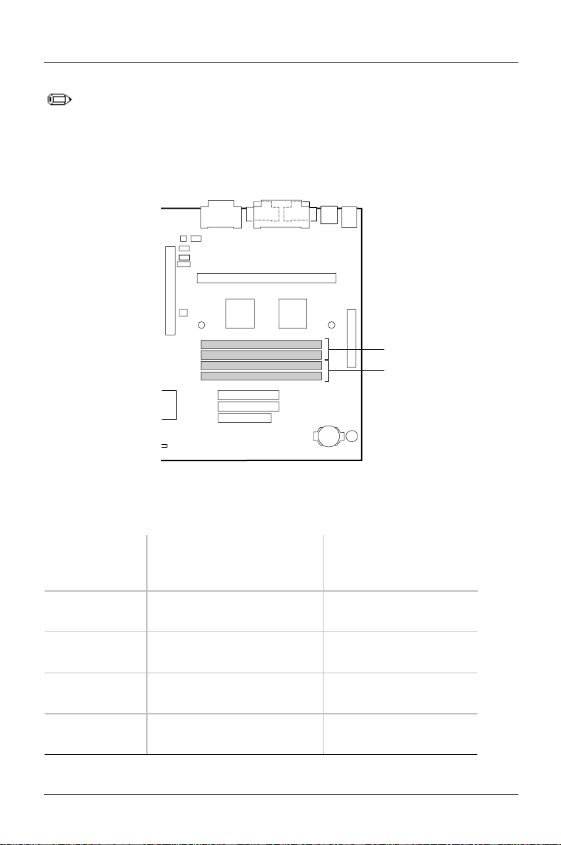
The motherboard has four 72-pin, tin-lead SIMM sockets that support from 8 MB to
256 MB of memory. The sockets are arranged as banks 0 and 1 (Figure 6). Two
sockets make up one bank.
When adding memory, follow these guidelines:
• When adding SIMMs, use only tin-lead,
72-pin, 50 or 60 ns EDO DRAM. Faster devices will not improve system
performance.
• When you install SIMMs, you must completely fill at least one bank; that is,
you must install SIMMs in both sockets of the bank.
• The computer automatically detects the installed memory, so it doesn't matter
which bank is used, as long as both sockets in the bank are filled. Because of
limited space on the motherboard, it might be easier to install SIMMs in bank
0 first.
• Both SIMMs in one bank must be the same size. For example, don't install a 4
MB SIMM in one socket of bank 0 and an 8 MB SIMM in the second socket of
bank 0. You may, however, use different size SIMMs in different banks.
A26361-D1005-Z120-2-7619
49
Page 58
Installing and Configuring Motherboard Options
The motherboard supports parity (x36) or non-parity (x32) SIMMs. Error
checking and correction is supported with parity and ECC SIMMs. There
is no error checking and correction with non-parity SIMMs.
Figure 6. Location of SIMM Sockets
0
1
Table 5. Memory Options for SIMM Sockets
For a total
system
memory of
8 MB 4 MB (8 MB total in socket
16 MB 4 MB (8 MB total in socket
16 MB 8 MB (16 MB total in socket
32 MB 8 MB (16 MB total in socket
50
Install a SIMM of the
following size in both
sockets of bank 0
bank 0)
bank 0)
bank 0)
bank 0)
OM05686
Install a SIMM of the
following size in both
sockets of bank 1
Empty
4 MB (8 MB total in
socket bank 1)
Empty
8 MB (16 MB total in
socket bank 1)
A26361-D1005-Z120-2-7619
Page 59

Installing and Configuring Motherboard Options
For a total
system
memory of
32 MB 16 MB (32 MB total in socket
Install a SIMM of the
following size in both
sockets of bank 0
Install a SIMM of the
following size in both
sockets of bank 1
Empty
bank 0)
64 MB 16 MB (32 MB total in socket
bank 0)
64 MB 32 MB (64 MB total in socket
16 MB (32 MB total in
socket bank 1)
Empty
bank 0)
128 MB 32 MB (64 MB total in socket
bank 0)
128 MB 64 MB (128 MB total in
32 MB (64 MB total in
socket bank 1)
Empty
socket bank 0)
256 MB 64 MB (128 MB total in
socket bank 0)
64 MB (128 MB total in
socket bank 1)
To install SIMMs, do the following:
Observe the precautions in "Before You Begin” (see page 41).
Turn off all peripheral devices connected to the computer. Turn off the
computer.
Remove the computer cover.
Holding the SIMM only by the edges, remove it from its antistatic package.
Position the SIMM at about a 45° angle relative to the motherboard. Make
sure the small notch in the middle of the bottom edge of the SIMM aligns with
the notch in the SIMM socket.
Insert the bottom edge of the SIMM into the SIMM socket and make sure it is
seated firmly.
When the SIMM seats correctly, hold it at each end and gently push the top
edge towards the retaining clips of the connector until the SIMM snaps into
place (Figure 7). If the SIMM does not install correctly, gently spread the
retaining clips just enough so that you can pull away the top edge of the SIMM
and try again.
Reinstall and reconnect any parts you removed or disconnected to gain
access to the SIMM sockets.
Replace the computer cover.
A26361-D1005-Z120-2-7619
51
Page 60

Installing and Configuring Motherboard Options
Figure 7. Installing a SIMM
How to Remove Memory
To remove a SIMM, do the following:
OM05687
Observe the precautions in "Before You Begin" (see page 41).
Turn off all peripheral devices connected to the computer.
Turn off the computer.
Remove the computer cover.
Gently spread the retaining clip at each end of the SIMM socket, just enough
to allow you to rotate the top edge of the SIMM downward to an angle of
about 45°.
Holding the SIMM only by the edges, lift it away from the socket, and store it
in an antistatic package.
Reinstall and reconnect any parts you removed or disconnected to gain
access to the SIMM sockets.
Replace the computer cover.
52
A26361-D1005-Z120-2-7619
Page 61

Installing and Configuring Motherboard Options
How to Replace the Battery
When your computer is turned off, a lithium battery keeps the time-of-day clock
and the values in CMOS RAM current. Figure 8 shows the location of the battery.
The battery should last about seven years. When the battery begins to die, it loses
voltage; when the voltage drops below a certain level, the Setup program settings
stored in CMOS RAM (for example, the date and time) might not be accurate. If
the battery dies, replace it with an equivalent battery.
If your local ordinances permit, you may dispose of individual batteries as normal
trash. Do not expose batteries to excessive heat or fire. Keep all batteries away
from children.
Danger of explosion if the battery is incorrectly replaced. Replace only
with the same or equivalent type recommended by the equipment
!
manufacturer. Discard used batteries according to manufacturer's
instructions.
Il y a danger d'explosion s'li y a remplacement incorrect de la batterie.
Remplacer uniquement avec une batterie du méme type ou d'un type
recommandé par le constructeur. Mettre au rébut les batteries usagées
conformément aux instructions du fabricant.
Lithiumbatteri - Eksplosionsfare ved fejlagtig håndtering. Udskiftning må
kun ske med batteri af samme fabrikat og type. Levér det brugte batteri
tilbage til leverandøren.
Lithiumbatteri - Eksplosjonsfare. Ved utskifting benyttes kun batteri som
anbefalt av apparatfabrikanten. Brukt batteri returneres
apparatleverandøren.
Explosionsfara vid felaktigt batteribyte. Använd samma batterityp eller en
ekvivalent typ som rekommenderas av apparattillverkaren. Kassera
använt batteri enligt fabrikantens instruktion.
Paristo voi räjähtää, jos se on virheellisesti asennettu. Vaihda paristo
ainoastaan laitevalmistajan suosittelemaan tyyppiin. Hävitä käjtetty
paristo valmistajan ohjeiden mukaisesti.
To replace the battery (see Figure 8):
Observe the precautions in "Before You Begin” (see page 41).
Turn off all peripheral devices connected to the computer. Turn off the
computer.
A26361-D1005-Z120-2-7619
53
Page 62
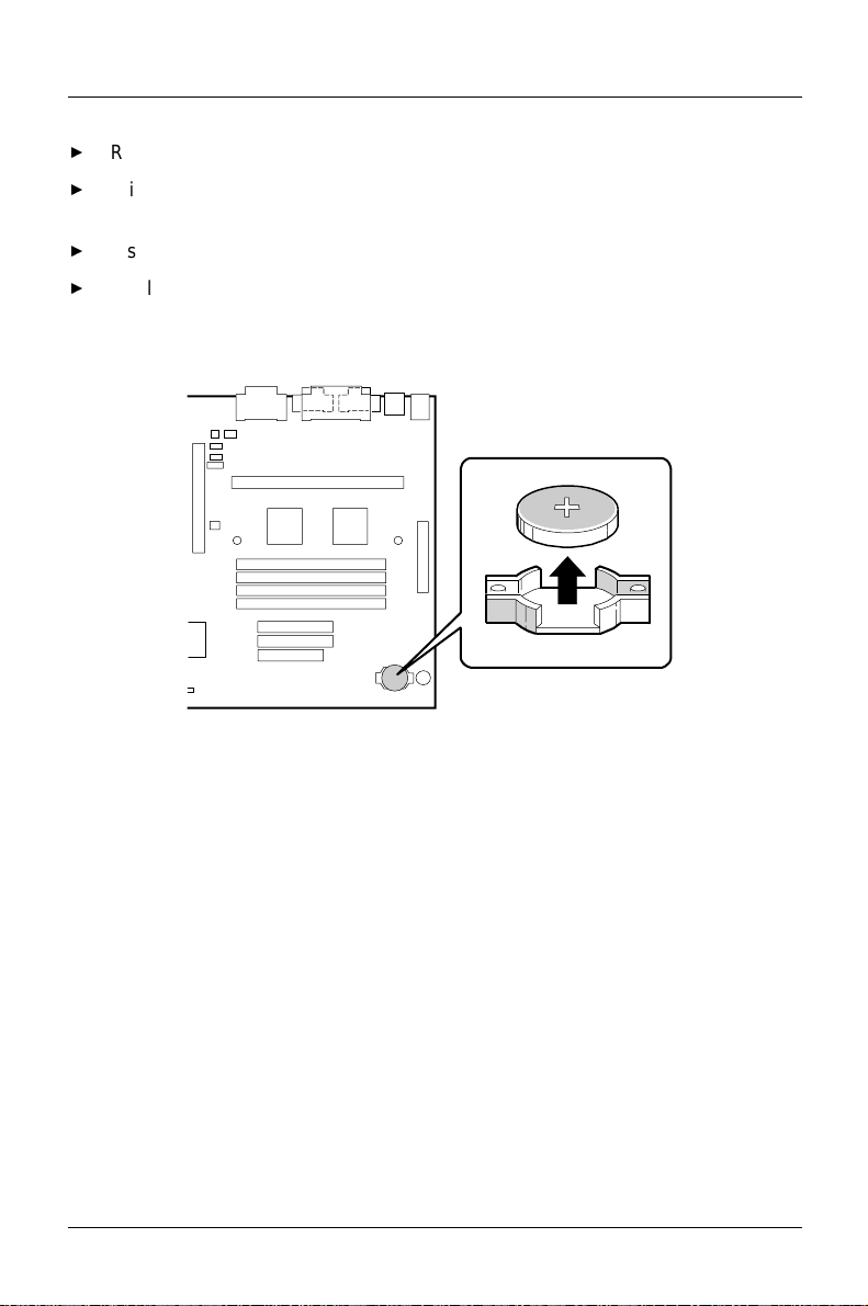
Installing and Configuring Motherboard Options
Remove the computer cover.
With your fingers, gently pry the battery free from its socket, taking care to
note the "+" and "-" orientation of the battery.
Install the new battery in the socket.
Replace the computer cover.
Figure 8. Replacing the Battery
54
OM05688
A26361-D1005-Z120-2-7619
Page 63

Error messages
This chapter contains error messages generated by the system board.
BIOS Beep Codes
One long beep followed by several short beeps indicates a video problem.
Table 6. Beep Codes
Beeps Error Message Description
1 Refresh Failure The memory refresh circuitry on the
motherboard is faulty.
2 Parity Error A parity error occurred in system memory.
3 First Bank Memory
Failure
4 Timer Not
Operational
5 Processor Error The processor generated an error.
6 Keyboard Controller
Failure
7 Processor Exception
Interrupt Error
8 Display Memory
Read/Write Error
9 ROM Checksum
Error
10 CMOS Shutdown
Register Read/Write
Error
Memory failure in the first bank of memory.
Memory failure in the first bank of memory or
Timer 1 on the motherboard is not
functioning.
The keyboard controller may be bad. The
BIOS cannot switch to protected mode.
The processor generated an exception
interrupt.
The system video adapter is either missing or
its memory is faulty. This is not a fatal error.
ROM checksum value does not match the
value encoded in the BIOS.
The shutdown register for CMOS RAM failed.
A26361-D1005-Z120-2-7619
55
Page 64

Error messages
PCI Configuration Error Messages
The following PCI messages are displayed as a group with bus, device and
function information.
Table 7. PCI Configuration Error Messages
Message Explanation
Bad PnP Serial ID
Checksum
Floppy Disk Controller
Resource Conflict
NVRAM Checksum Error,
NVRAM Cleared
NVRAM Cleared By Jumper The "CMOS Clear” jumper has been moved to
NVRAM Data Invalid,
NVRAM Cleared
Parallel Port Resource
Conflict
PCI Error Log is Full This message is displayed when more than 15
PCI I/O Port Conflict Two devices requested the same resource,
PCI IRQ Conflict Two devices requested the same resource,
PCI Memory Conflict Two devices requested the same resource,
The Serial ID checksum of a Plug and Play card
was invalid.
The floppy disk controller has requested a
resource that is already in use.
The ESCD data was reinitialized because of an
NVRAM checksum error. Try rerunning the ICU.
the "Clear” position and CMOS RAM has been
cleared.
Invalid entry in the ESCD.
The parallel port has requested a resource that is
already in use.
PCI conflict errors are detected. No additional
PCI errors can be logged.
resulting in a conflict.
resulting in a conflict.
resulting in a conflict.
Primary Boot Device Not
Found
Primary IDE Controller
Resource Conflict
56
The designated primary boot device (hard disk
drive, diskette drive, CD-ROM drive, or network)
could not be found.
The primary IDE controller has requested a
resource that is already in use.
A26361-D1005-Z120-2-7619
Page 65

Message Explanation
Error messages
Primary Input Device Not
Found
Secondary IDE Controller
Resource Conflict
Serial Port 1 Resource
Conflict
Serial Port 2 Resource
Conflict
Static Device Resource
Conflict
System Device Resource
Conflict
The designated primary input device (keyboard,
mouse, or other, if input is redirected) could not
be found.
The secondary IDE controller has requested a
resource that is already in use.
Serial port 1 has requested a resource that is
already in use.
Serial port 2 has requested a resource that is
already in use.
A non Plug and Play ISA card has requested a
resource that is already in use.
A non Plug and Play ISA card has requested a
resource that is already in use.
BIOS Error Messages
Table 8. BIOS Error Messages
Error Message Explanation
A20 Error Gate A20 on the keyboard controller is not working.
Address Line
Short!
CH-2 Timer Error Most systems include two timers. There is an error in
CMOS Battery
State Low
CMOS Checksum
Failure
CMOS Display
Type Mismatch
A26361-D1005-Z120-2-7619
Error in the address decoding circuitry on the baseboard.
timer 2.
The battery power is low. Replace the battery.
After CMOS RAM values are saved, a checksum value is
generated for error checking. The previous value is
different from the current value. Run Setup.
The video type in CMOS RAM does not match the type
detected by the BIOS. Run Setup.
57
Page 66

Error messages
Error Message Explanation
CMOS Memory
Size Mismatch
CMOS System
Options Not Set
CMOS Time and
The amount of memory on the motherboard is different
than the amount indicated in CMOS RAM. Run Setup.
The values stored in CMOS RAM are either corrupt or
nonexistent. Run Setup.
Run Setup to set the date and time in CMOS RAM.
Date Not Set
Diskette Boot
Failure
The boot disk in floppy drive A is corrupt. It cannot be
used to boot the system. Use another boot disk and follow
the screen instructions.
DMA Error Error in the DMA controller.
DMA #1 Error Error in the first DMA channel.
DMA #2 Error Error in the second DMA channel.
FDD Controller
Failure
The BIOS cannot communicate with the floppy disk drive
controller. Check all appropriate connections after the
system is powered down.
HDD Controller
Failure
The BIOS cannot communicate with the hard disk drive
controller. Check all appropriate connections after the
system is powered down.
INTR #1 Error Interrupt channel 1 failed POST.
INTR #2 Error Interrupt channel 2 failed POST.
Invalid Boot
Diskette
Keyboard Is
Locked...Unlock It
The BIOS can read the disk in floppy drive A, but cannot
boot the system. Use another boot disk.
The keyboard lock on the computer is engaged. Unlock
the computer to continue.
Keyboard Error There is a timing problem with the keyboard.
KB/Interface Error There is an error in the keyboard controller
Off Board Parity
Error
Parity error in memory installed in an expansion slot. The
format is:
OFF BOARD PARITY
ERROR ADDR (HEX) =
(xxxx)
where xxxx is the address where the error occurred.
58
A26361-D1005-Z120-2-7619
Page 67

Error Message Explanation
Error messages
On Board Parity
Error
Parity Error Parity error in system memory at an unknown address.
Parity error detected in system memory.
ISA NMI Messages
Table 9. ISA NMI Messages
ISA NMI Message Explanation
Memory Parity
Error at xxxxx
I/O Card Parity
Error at xxxxx
DMA Bus Time-out A device has driven the bus signal for more than 7.8
Memory failed. If the memory location can be
determined, it is displayed as xxxxx. If the memory
location cannot be determined, the message is: Memory
Parity Error ????.
An expansion card failed. If the address can be
determined, it is displayed as xxxxx. If the address
cannot be determined the message is: I/O Card Parity
Error ????.
microseconds.
A26361-D1005-Z120-2-7619
59
Page 68

Page 69
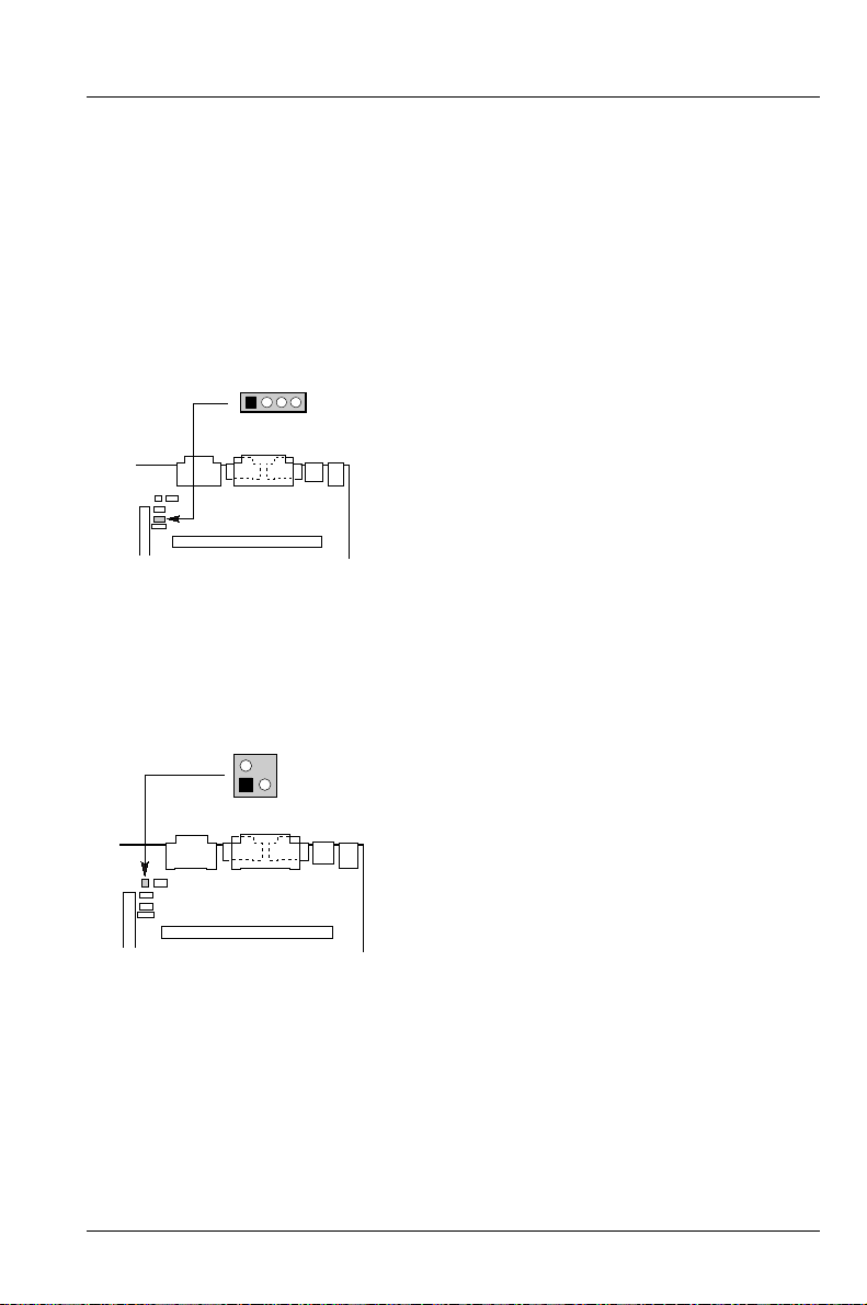
Technical Reference
Motherboard Connectors
CD-ROM Audio Connector
Table 10. CD-ROM Audio Connector Pinout
J2F6
14
OM05695
Telephony Connector
Table 11. Telephony Connector Pinout
2
J2F1
13
OM05696
Pin
1
2
3
4
Pin
1
2
3
4
Signal Name
Ground
CD-Left
Ground
CD-Right
Signal Name
Ground
Mono In
Mono Out
Key
A26361-D1005-Z120-2-7619
61
Page 70
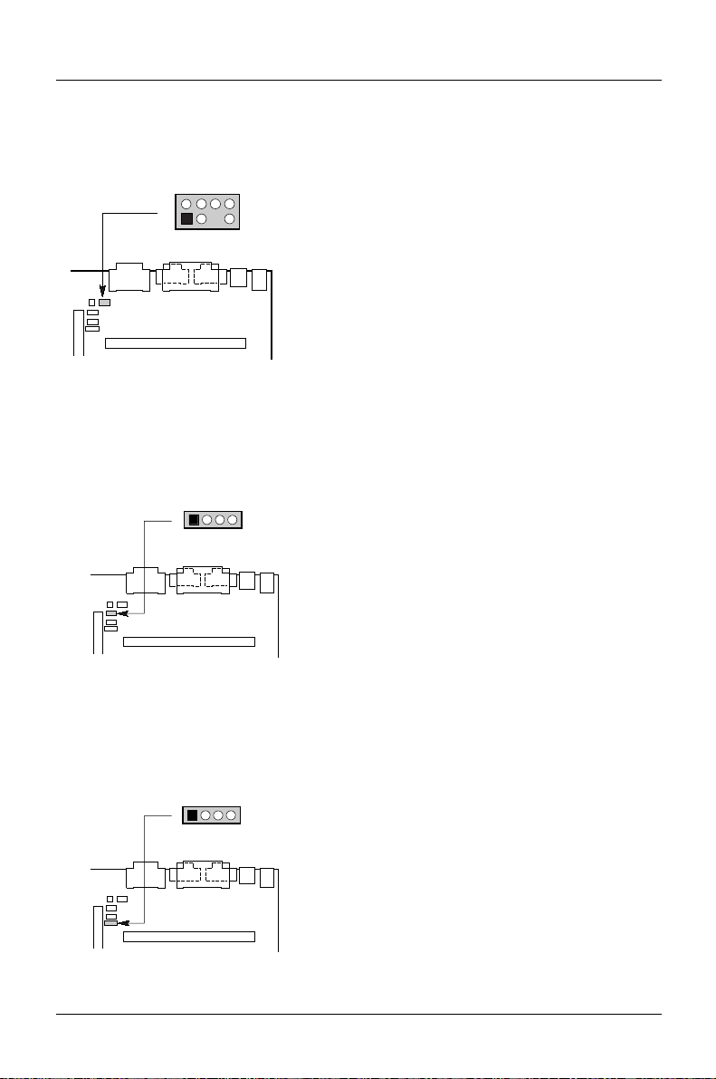
Technical Reference
Wavetable Connector
Table 12. Wavetable Connector Pinout
2
1
J2F2
8
7
OM05697
Telephony Connector
Table 13. Telephony Connector Pinout
Pin
Signal Name
1
Waveright
2
Ground
3
Waveleft
4
Ground
Pin
Signal Name
5
Key
6
Ground
7
No connection
8
MIDI_OUT
J2F3
14
OM05698
Audio Line In Connector
Table 14. Audio Line In Connector Pinout
J3F1
14
OM05699
Pin
1
2
3
4
Pin
1
2
3
4
Signal Name
Mono In
Ground
Ground
Mono Out
Signal Name
Left Line In
Ground
Ground
Right Line In (monaural)
62
A26361-D1005-Z120-2-7619
Page 71
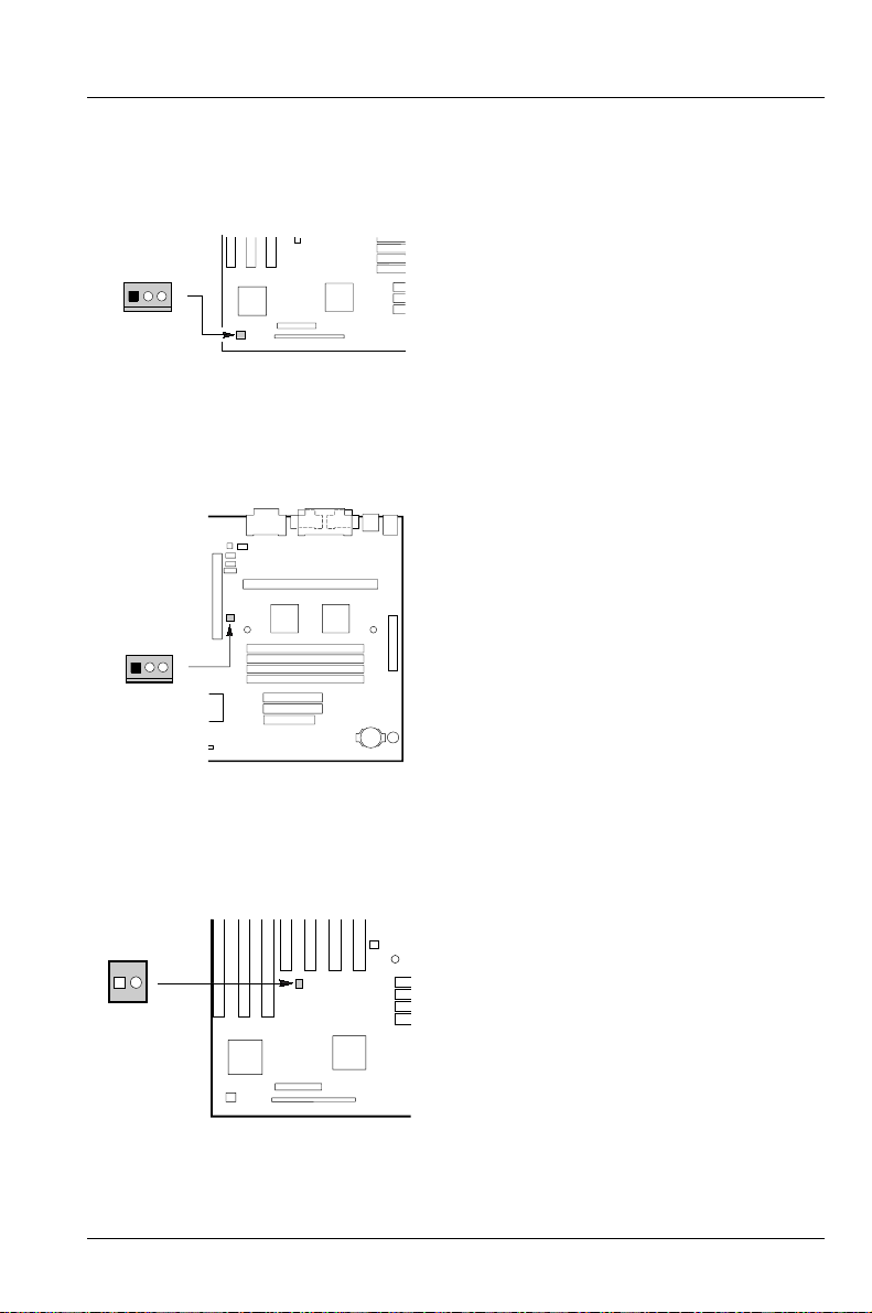
Fan 1 Connector
Table 15. Fan 1 Connector Pinout
Technical Reference
J9A1
1
3
OM05707
Fan 3 Connector
Table 16. Fan 3 Connector Pinout
J4F1
3
1
OM05708
Chassis Security Connector
Pin
1
2
3
Pin
1
2
3
Signal Name
Ground
+12 V
FAN_SEN
Signal Name
Ground
+12 V
FAN_SEN
Table 17. Chassis Security Connector Pinout
J6C1
12
A26361-D1005-Z120-2-7619
OM05707A
Pin
1
2
Signal Name
Ground
CHS_SEC
63
Page 72
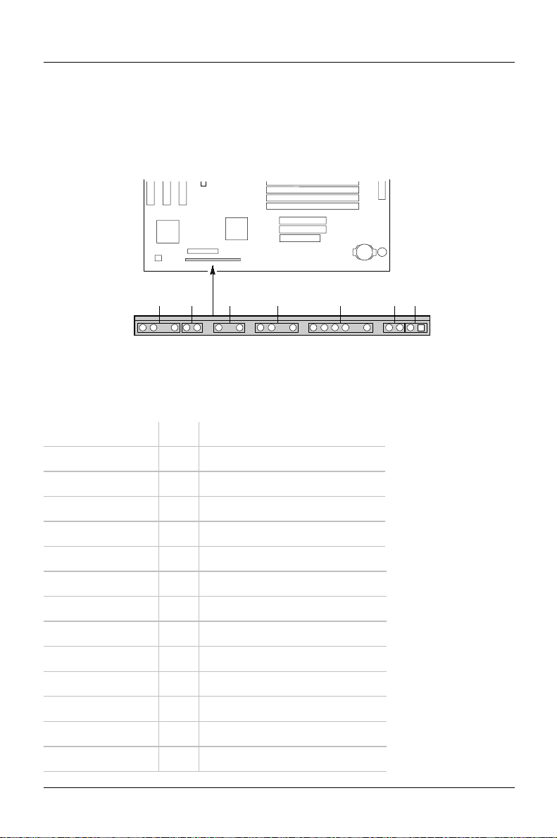
Technical Reference
Front Panel Connectors
The motherboard has connectors for controls and indicators typically located on
the front panel of the computer.
AB C D E FG
27
Table 18. Front Panel Connectors
Connector Pin Signal Name
A. Speaker* 27 SPKR_HDR
26 PIEZO_IN
25 Key
24 Ground
B. Reset switch 23 SW_RST
22 Ground
Key
C. Power LED 20 +5 V
19 Key
18 Ground
Key
D. Hard drive LED 16 +5 V
J9D1
1
24611162024 22
OM05705
64
15 HD Active#
A26361-D1005-Z120-2-7619
Page 73

Connector Pin Signal Name
14 Key
13 +5 V
Key
E. Infrared 11 CONIR (consumer IR)
10 IrTX (transmit)
9 Ground
8 IrRX (receive)
7 Key
6 +5 V
Key
F. Sleep switch 4 +5 V
3 SLEEP
G. Power switch 2 Ground
1 SW_ON#
* A jumper on pins 26-27 enables the onboard speaker.
Technical Reference
A26361-D1005-Z120-2-7619
65
Page 74

Technical Reference
Motherboard Resources
Memory Map
Table 19. Memory Map
Address
Range
(Decimal)
Address
Range (hex) Size Description
1024K262144K
960K-1024K F0000-FFFFF 64K System BIOS
944K-960K EC000-EFFFF 16K Boot Block
936K-944K EA000-EBFFF 8K ESCD (Plug and Play configuration
932K-936K E9000-E9FFF 4K Reserved for BIOS
928K-932K E8000-E8FFF 4K OEM logo area
896K-928K E0000-E7FFF 32K BIOS reserved
800K-896K C8000-DFFFF 96K Available high DOS memory (open to
640K-800K A0000-C7FFF 160K Video memory and BIOS
639K-640K 9FC00-9FFFF 1K Extended BIOS Data (moveable by
512K-639K 80000-9FBFF 127K Extended conventional memory
0K-512K 00000-7FFFF 512K Conventional memory
10000010000000
255M Extended memory
area)
ISA and PCI bus)
memory management software)
66
A26361-D1005-Z120-2-7619
Page 75

Technical Reference
I/O Map
Table 20. I/O Map
Address (hex) Size Description
0000 - 000F 16 bytes PIIX3 - DMA 1
0020 - 0021 2 bytes PIIX3 - Interrupt Controller 1
002E - 002F 2 bytes I/O Controller Config. Reg.
0040 - 0043 4 bytes PIIX3 - Timer 1
0048 - 004B 4 bytes PIIX3 - Timer 2
0060 1 byte Keyboard Controller Byte - Reset IRQ
0061 1 byte PIIX3 - NMI, speaker control
0064 1 byte Keyboard Controller, CMD/STAT Byte
0070, bit 7 1 bit PIIX3 - Enable NMI
0070, bits 6:0 7 bits PIIX3 - Real Time Clock, Address
0071 1 byte PIIX3 - Real Time Clock, Data
0078 1 byte Reserved - Brd. Config.
0079 1 byte Reserved - Brd. Config.
0080 - 008F 16 bytes PIIX3 - DMA Page Registers
00A0 - 00A1 2 bytes PIIX3 - Interrupt Controller 2
00B2 - 00B3 2 bytes APM Control
00C0 - 00DE 31 bytes PIIX3 - DMA 2
00F0 1 byte Reset Numeric Error
0170 - 0177 8 bytes Secondary IDE Channel
01F0 - 01F7 8 bytes Primary IDE Channel
0200 - 0207 8 bytes Game Port
0220 - 022F 16 bytes Audio
0240 - 024F 16 bytes Audio
A26361-D1005-Z120-2-7619
67
Page 76

Technical Reference
Address (hex) Size Description
0278 - 027F 8 bytes Parallel Port 2
0295 1 byte Hardware monitor
0296 1 byte Hardware monitor
02E8 - 02EF 8 bytes Serial Port 4/Video (8514A)
02F8 - 02FF 8 bytes Serial Port 2
0300 - 0301 2 bytes MPU-401 (MIDI)
0330 - 0331 2 bytes MPU-401 (MIDI)
0332 - 0333 2 bytes MPU-401 (MIDI)
0334 - 0335 2 bytes MPU-401 (MIDI)
0376 1 byte Sec. IDE Chan. Cmd. Port
0377 1 byte Floppy Chan. 2 Cmd.
0377, bit 7 1 bit Floppy Disk Chg. Chan. 2
0377, bits 6:0 7 bits Sec. IDE Chan. Status Port
0378 - 037F 8 bytes Parallel Port 1
0388 - 038D 6 bytes FM Synthesizer
03B4 - 03B5 2 bytes VGA
03BA 1 byte VGA
03BC - 03BF 4 bytes Parallel Port 3
03C0 - 03CA 2 bytes VGA
03CC 1 byte VGA
03CE - 03CF 2 bytes VGA
03D4 - 03D5 2 bytes VGA
03DA 1 byte VGA
03E8 - 03EF 8 bytes Serial Port 3
03F0 - 03F5 6 bytes Floppy Channel 1
03F6 1 byte Pri. IDE Chan. Cmd. Port
68
A26361-D1005-Z120-2-7619
Page 77

Address (hex) Size Description
03F7 (Write) 1 byte Floppy Chan.1 Cmd.
03F7, bit 7 1 bit Floppy Disk Chg. Chan. 1
03F7, bits 6:0 7 bits Pri. IDE Chan. Status Port
03F8 - 03FF 8 bytes Serial Port 1
04D0 - 04D1 2 bytes Edge/level triggered PIC
0530 - 0537 8 bytes Windows Sound System
0604 - 060B 8 bytes Windows Sound System
LPT + 400h 8 bytes ECP port, LPT + 400h
0CF8 - 0CFB* 4 bytes PCI Config. Address Reg.
0CF9** 1 byte Turbo & Reset Control Reg.
0CFC - 0CFF 4 bytes PCI Config. Data Reg.
0E80 - 0E87 8 bytes Windows Sound System
0F40 - 0F47 8 bytes Windows Sound System
0F86 - 0F87 2 bytes Yamaha OPL3-SA Config.
Technical Reference
FF00 - FF07 8 bytes IDE Bus Master Reg.
FFA0 - FFA7 8 bytes Pri. Bus Master IDE Reg.
FFA8 - FFAF 8 bytes Sec. Bus Master IDE Reg.
* Only by DWORD accesses. **Only by Byte accesses.
A26361-D1005-Z120-2-7619
69
Page 78

Technical Reference
PCI Configuration Space Map
Table 21. PCI Configuration Space Map
Bus
Number
(hex)
00 00 00 Intel 82441FX (PMC)
00 07 00 Intel 82371SB (PIIX3) PCI/ISA Bridge
00 07 01 Intel 82371SB (PIIX3) IDE Bus Master
00 07 02 Intel 82371SB (PIIX3) USB
00 0B 00 PCI Expansion Slot 1 (J4E2)
00 0F 00 PCI Expansion Slot 2 (J4E1)
00 01 00 PCI Expansion Slot 3 (J4D1)
00 13 00 PCI Expansion Slot 4 (J4C1)
Device
Number
(hex)
Function
Number
(hex) Description
DMA Channels
Table 22. DMA Channels
DMA Data Width System Resource
0 8- or 16-bits Audio if present, else parallel port
1 8- or 16-bits Audio if present, else available
2 8- or 16-bits Floppy drive
3 8- or 16-bits Audio if present, else parallel port (for ECP/EPP
configuration)
4 16-bits Reserved - Cascade Channel
5 16-bits Available
6 16-bits Available
7 16-bits Available
70
A26361-D1005-Z120-2-7619
Page 79

Interrupts
Table 23. Interrupts
IRQ System Resource
NMI I/O channel check
0 Reserved, interval timer
1 Reserved, keyboard buffer full
2 Reserved, cascade interrupt from slave PIC
3 Serial Port 2
4 Serial Port 1
5 Parallel Port 2
6 Floppy drive
7 Parallel Port 1
8 Real-time clock
9 User available
Technical Reference
10 User available
11 Audio if present, else user available
12 Onboard mouse port if present, else user available
13 Reserved, math coprocessor
14 Primary IDE if present, else user available
15 Secondary IDE if present, else user available
A26361-D1005-Z120-2-7619
71
Page 80

Page 81

Upgrading the BIOS
This chapter explains how to use the BIOS upgrade utility and how to recover the
BIOS if an upgrade fails.
Record the Current BIOS Settings
Boot the computer and press <F1> when you see the message:
Press <F1> Key if you want to run SETUP
Do not skip step 2. You will need these settings to configure your
computer at the end of the procedure.
Write down the current settings in the BIOS Setup program (see
BIOS Setup Program
).
How to Upgrade the BIOS
To upgrade the BIOS, you will need the Flash upgrade utility, the files containing
the new BIOS, and the files for BIOS recovery.
To obtain these files, contact your computer supplier.
Using the
The following steps explain how to upgrade the BIOS.
Make a Copy of the Current BIOS
Insert the bootable floppy disk with the upgrade files into drive A of the
computer you want to upgrade.
Boot the computer. The BIOS Upgrade Utility appears.
To go to the Main menu, press <Enter>.
Select Save Flash Memory to a File.
Select Save System BIOS.
A26361-D1005-Z120-2-7619
73
Page 82

Upgrading the BIOS
Type the path and file name (with the .bio extension) for the saved BIOS. For
example:
A:\oldbios.bio
Press <Enter>.
If there is not enough space on the disk, use another pre-formatted floppy
disk to save the old BIOS.
Type a description of this BIOS in the Image Title area.
For example:
Old BIOS as of 10 Oct 96
Press <Enter>.
To copy the current BIOS to the floppy disk, press <Enter>.
When the copy is complete, the Main menu displays.
If you used a different floppy disk to save the old BIOS, remove it. Insert the
BIOS upgrade floppy disk in drive A.
Upgrade the BIOS
Boot the computer. The BIOS Upgrade Utility appears.
Select Update Flash Memory From a File.
Select Update System BIOS. Press <Enter>.
Use the arrow keys to select the correct .bio file. Press <Enter>.
When the utility asks for confirmation that you want to load the new Flash into
memory, select Continue with Programming. Press <Enter>.
When the utility displays the message upgrade is complete, remove the floppy
disk. Press <Enter>.
As the computer boots, check the BIOS identifier (version number) to make
sure the upgrade was successful.
To enter the Setup program, press <F1> when you see the message:
Press <F1> Key if you want to run SETUP
For proper operation you must load the Setup program defaults. To load the
defaults, press <F5>.
To accept the defaults, press <Enter>.
74
A26361-D1005-Z120-2-7619
Page 83
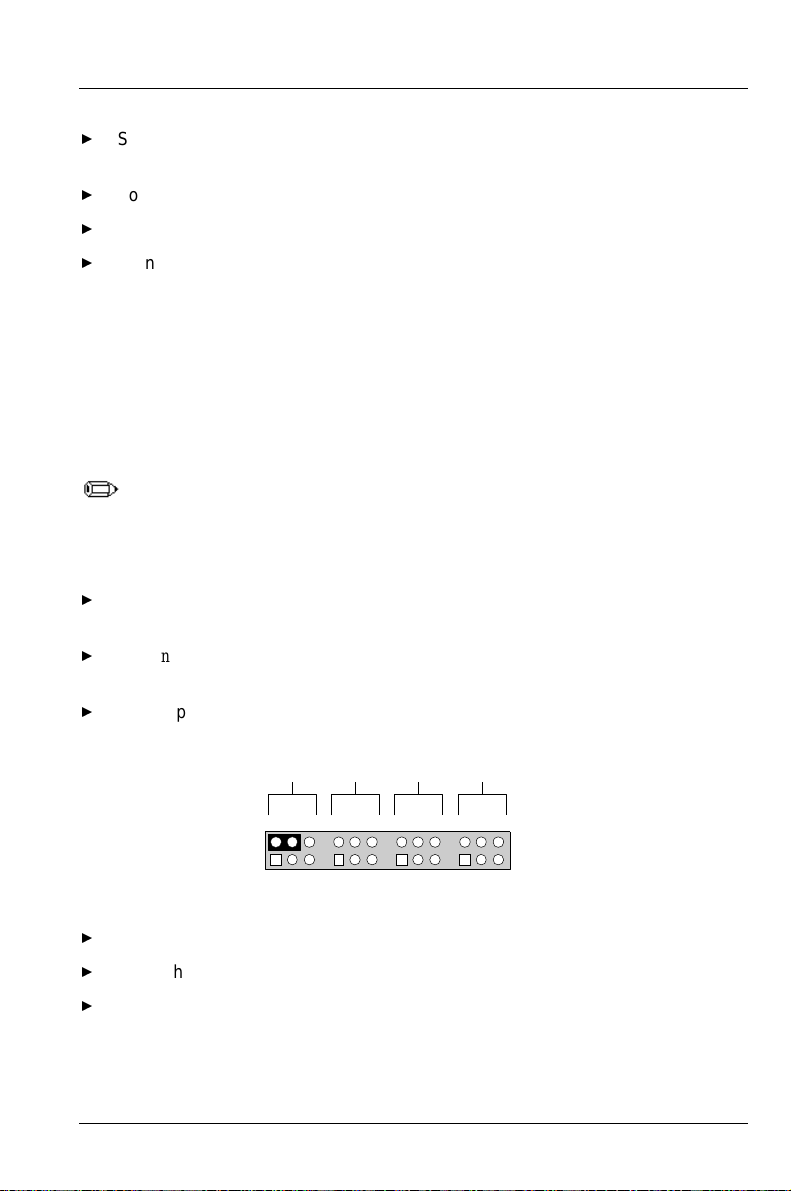
Upgrading the BIOS
Set the options in the Setup program to the settings that you wrote down
before the BIOS upgrade.
To save the settings, press <F10>.
To accept the settings, press <Enter>.
Turn off the computer and reboot.
How to Recover the BIOS If an Upgrade Fails
It is unlikely that anything will interrupt the BIOS upgrade; however, if an
interruption occurs, the BIOS could be damaged. The following steps explain how
to recover the BIOS if an upgrade fails.
Because of the small amount of code available in the non-erasable boot
block area, there is no video support. You will not see anything on the
screen during the procedure. Monitor the procedure by listening to the
speaker and looking at the floppy drive LED.
Turn off the computer and disconnect the AC power cord from the computer.
Remove the computer cover.
See
Installing and configuring motherboard options
(Figure 3) for the location of
the BIOS recovery jumper.
On jumper block J9C1-A, move the jumper from pins 5-6 to pins 4-5 as shown
below.
A B C D
465
Replace the computer cover.
Insert the bootable BIOS upgrade floppy disk into floppy drive A.
Reconnect the AC power cord and turn on the computer. The recovery
465
32
465
3211
465
J9C1
321
321
OM05709
process will take a few minutes.
A26361-D1005-Z120-2-7619
75
Page 84
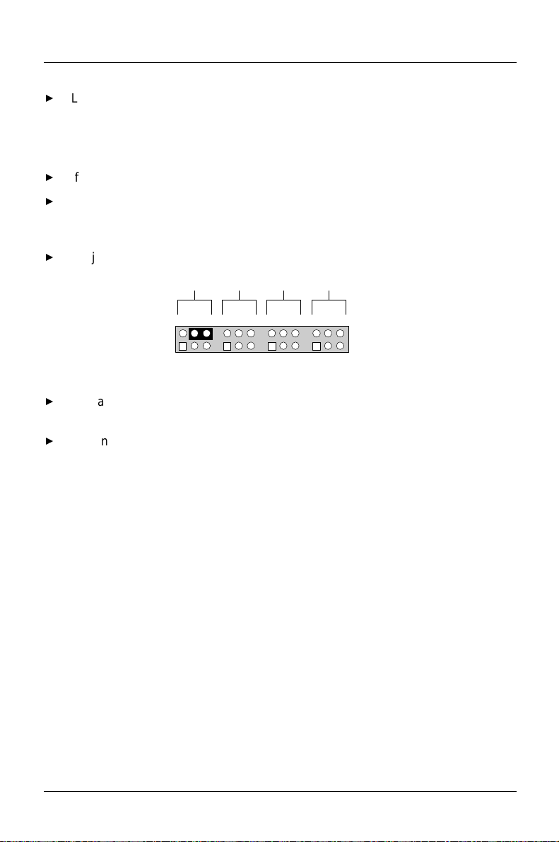
Upgrading the BIOS
Listen to the speaker.
− Two beeps and the end of activity in drive A indicate successful BIOS
recovery.
− A series of continuous beeps indicates failed BIOS recovery.
If recovery fails, return to step 1 and repeat the recovery process.
If recovery is successful, turn off the computer and disconnect the AC power
cord from the computer. Remove the computer cover and continue with the
following steps.
On jumper block J9C1-A, move the jumper back to pins 5-6 as shown below.
A B C D
465
Replace the computer cover and reconnect the AC power cable; leave the
465
32
465
3211
465
J9C1
321
321
OM05710
upgrade disk in drive A and turn on the computer.
Continue with the BIOS upgrade (see "Upgrading the BIOS").
76
A26361-D1005-Z120-2-7619
Page 85

Index
A
Add-in boards 6 See also PCI or ISA
Administrative Password 37
Advanced Power Management 29
Advanced Screen 21
Audio
Interface 26
Line In Connector 62
Auto Start On AC Loss 30
Auto-configuration
IDE drives 5
ISA cards 5
PCI cards 5
B
Bank 0 28
Bank 1 28
Base Memory Size 27
Battery 6
Beep codes 55
BIOS
Beep Codes 55
Error messages 57
Features 5
Settings 73
Setup 9
Upgrades 6
Boot
Options Subscreen 16
Speed 18
C
CD-ROM Audio Connector 61
Chassis Security Connector 63
Chipset Configuration Subscreen 27
Clear
Event Log 33
User Password 38
CMOS RAM 6
A26361-D1005-Z120-2-7619
77
Page 86

Index
Configuration Mode 30
Configuring Motherboard Options 41
CPU See microprocessor
Cylinders 15
D
Discard Changes 39
DMA Channels 70
DRAM See memory
E
Enter Password 37
Error messages 55
Beep codes 55
BIOS 57
ISA NMI 59
PCI configuration 56
Event Log
Capacity 33
Control 33
Count Granularity 33
Event Logging Configuration Subscreen 32
Event Time Granularity 33
Exit
Discarding Changes 39
Saving Changes 39
Screen 39
Expansion slots 6
F
Fan 1 Connector 63
Fan 3 Connector 63
Fan connector 7
Fast Programmed I/O Modes 16
First Boot Device 17
Floppy
Access 14
Interface 23
Options Subscreen 13
Status 26
Floppy A 13
Type 13
Floppy B 13
78
A26361-D1005-Z120-2-7619
Page 87

Type 14
Fourth Boot Device 18
Front Panel Connectors 64
H
Hard Disk Pre-Delay 19
Hard drive support 4
Hardware Monitor
Interface 26
Option 8
Heads 15
Hot Key 30
I
I/O features 4
I/O Map 67
IDE
Auto-configuration 5
Device Configuration 15
Drive Power Down 29
Peripheral interface 4
Translation Mode 16
Inactivity Timer 29
Infrared support 4
Install
a Processor 46
Memory 49
the Processor 46
Installing Motherboard Options 41
Interrupts 71
IRQ 32
ISA
LFB
Base Address 27
Size 27
NMI messages 59
Plug and Play Capability 5
Shared Memory
Base Address 32
Size 31
VGA Write Combining 28
Index
A26361-D1005-Z120-2-7619
79
Page 88

Index
J
Jumpers 42
for Setup Program 43
L
Latency Timer (PCI Clocks) 28
Load Setup Defaults 39
M
Make a Copy of the Current BIOS 73
Mark Existing Events as Read 33
Maximum Capacity 15
Memory
Error Detection 28
Support 1
Messages 55
Microprocessor description 1
Motherboard Connectors 61
Multiple
Sector Setting 16
Multiple Bit ECC Events 34
Subscreen 35
N
Num Lock 18
P
Parallel Port
Interface 25
Status 27
Type 25
Parity Error Events 34
Subscreen 35
Password 37
PCI
Auto-configuration 5
Configuration 70
Error messages 56
Pentium Pro microprocessor 1
Peripheral Configuration Subscreen 22
Plug and Play Configuration Subscreen 30
PnP OS 30
Power Management Configuration Subscreen 29
80
A26361-D1005-Z120-2-7619
Page 89

Power-On COM1 Ring 21
Pre-Boot Events 34
Subscreen 36
Primary IDE Master/Slave Configuration Subscreens 14
Primary PCI IDE
Interface 22
Status 26
R
RAM See memory
Real-time clock 6
Remove Processor 48
Removing SIMMs 52
Replace Battery 53
RTC See real-time clock
S
Scan User Flash Area 20
Second Boot Device 17
Secondary IDE Master/Slave Configuration Subscreens 14
Secondary PCI IDE
Interface 22
Status 26
Sectors 15
Security
Features 5
Hot Key (CTRL-ALT-) 39
Screen 36
Serial Port 1
Interface 23
Status 26
Serial Port 2
Interface 24
IR Mode 24
Status 26
Set
Administrative Password 37
Processor Speed Jumpers 48
Setup Prompt 19
SIMM removing 52
Single Bit ECC Events 34
Subscreen 34
Space Map 70
Index
A26361-D1005-Z120-2-7619
81
Page 90

Index
Speaker 6
System Cache 18
T
Technical Reference 61
Telephony Connector 61, 62
Third Boot Device 17
Typematic Rate 20
Delay 20
Programming 19
U
Unattended Start 38
Upgrade the BIOS 74
Upgrading the BIOS 73
USB Interface 25
Support 7
User
Password 37
Privilege Level 38
Using the BIOS Setup Program 9
V
VESA Video Power Down 29
Video Palette Snoop 27
W
Wavetable Connector 62
82
A26361-D1005-Z120-2-7619
 Loading...