

Page 1
Dieses Handbuch wurde auf Recycling-Papier gedruckt.
This manual has been printed on recycled paper.
Ce manuel est imprimé sur du papier recyclé.
Este manual ha sido impreso en papel reciclado.
Questo manuale è stato stampato su carta da riciclaggio.
PCPC
Denna handbok är tryckt på recyclingpapper.
Dit handboek werd op recycling-papier gedrukt.
System boards D841, D842
ISA/PCI
The Intel Inside Logo is
Technical Manual of Intel Corporation
a registered trademark
Published by
Siemens Nixdorf Informationssysteme AG
33094 Paderborn
81730 München
Order No.: A26361-D841-Z121-1-7619
Printed in the Federal Republic of Germany
AG 1195 11/95
A26361-D841-Z121-1-7619
Page 2

Is there ...
... any technical problem or other ... anything you want to tell us
question you need clarified? about this manual?
Please contact:
– one of our IT Service Shops
– your sales partner Siemens Nixdorf Informationssysteme AG
– your sales office User Documentation Department
You will find the addresses of the
IT Service Shops in the enclosed
warranty booklet. Fax: (0 89) 6 36-4 04 43
Please send us your comments quoting
the order number of the manual.
BS2000 OS ID4, Otto-Hahn-Ring 6,
81730 München, Germany
Page 3

Introduction
Important notes
System boards D841,
D842
ISA/PCI
Technical Manual
November 1995 edition
Settings
Add-on modules
Interface assignment and
IRQs
Error messages
Index
Your training needs . . .
The Siemens Nixdorf Training Centers offer you a wide range of
training courses in information technology and on IT products and
other subjects - onsite near to your workplace or offsite at one of our
training centers.
Contact us for information on consulting, course schedules and
selfstudy material.
Please write or fax:
Siemens Nixdorf Informationssysteme AG
Training Center, Beratungsservice
D-81730 München
Fax.: ..49 089 636-42945
Adaptec is a registered trademark of Adaptec Inc
Intel and Pentium are registered trademarks and OverDrive is a trademark of Intel
Corporation, USA.
Microsoft, MS and MS-DOS are registered trademarks and Windows is a trademark of
Microsoft Corporation.
PS/2 is a registered trademark of International Business Machines, Inc.
SCO and SCO UNIX are registered trademarks of Santa Cruz Operation.
VESA and DPMS are registered trademarks of Video Electronics Standards Association.
Copyright Siemens Nixdorf Informationssysteme AG 1995
All rights, including rights of translation, reproduction by printing, copying or similar methods,
even of parts are reserved.
Offenders will be liable for damages.
All rights, including rights created by patent grant or registration of a utility model or design,
are reserved.
Delivery subject to availability; right of technical modifications reserved.
Page 4
Contents
Contents
Introduction 1
Explanation of symbols
Features
Important notes
Notes on software
Settings
Setup menu
System Configuration page
The System Security Options page
Additional System Options page
PCI Device Configuration page
Additional Hard Disk Options page
Power Management Configuration page
Switch block and jumper
BIOS recovery
BIOS update
Write protection for floppy disk drive
Keyboard and pointing device
External cache
Add-on modules
Upgrading the processor
Upgrading main memory
Installing memory modules
Removing a memory module
Upgrading the video memory
Replacing the lithium battery
1
2
7
8
9
9
10
13
19
22
24
27
30
31
31
31
32
32
33
34
35
36
36
37
38
Connector for Imageport 43
Connector for monitor
Parallel interface
Pinout in SPP mode
Pinout in EPP mode
Pinout in ECP mode
Serial interface
PS/2 mouse port
PS/2 keyboard port
Interrupt Request Levels and DMA channels
Error messages
Index
44
45
45
46
46
47
48
48
49
51
63
Interface pinouts and interrupts
Connector for 5 V power supply
Connector for 3.3 V power supply
Connector for soft-off power supply
Connector for soft-off power switch
Connector for external loudspeaker
Connector for remote power-on
Connector for LED indicators
Connector for SCSI HD LED indicators
Connector for external monitor controller (VESA VGA pass-through)
A26361-D841-Z121-4-7619
39
39
39
40
40
40
40
41
41
42
A26361-D841-Z121-4-7619
Page 5

Introduction
Introduction
This description applies for the system boards D841 and D842 with PCI Bus
(Peripheral Component Interconnect). Unless otherwise specified, the settings
described apply for both system boards.
Explanation of symbols
The meanings of the symbols and fonts used in this manual are as follows:
This indicates instructions which it is essential to observe. Failure to do so
may endanger your health, the operational integrity and electrical safety of
!
your PC, or the security of your data.
This symbol is followed by supplementary information, remarks and tips.
i
Texts which follow this symbol describe activities that must be performed in the
order shown.
This symbol means that you must enter a blank space at this point.
↵ This symbol means that you must press the Enter key.
Texts in this typeface are screen outputs from the PC.
Texts in this bold typeface are the entries you make via the keyboard.
Texts in italics indicate commands or menu items.
"Quotation marks" indicate highlighted text and names of chapters.
Features
– 64-bit microprocessor Pentium with 16 Kbyte internal cache (first level cache;
8 Kbyte data cache, 8 Kbyte address cache)
or OverDrive processor for Pentium
– Math coprocessor: integrated in processor
– Memory configuration on system board: 8 Mbyte to 128 Mbyte RAM onboard
– Second level cache on the system board: 256 Kbytes
– PCI bus
– Disk controller connected to PCI bus for up to four IDE drives
(e.g. fast IDE hard disk drives, IDE CD ROM drive)
– Monitor controller connected to PCI bus; graphics processor
TSENG ET4000/W32P with Windows accelerator and 1 Mbyte or 2 Mbyte
DRAM video memory
– Real-time clock/calendar with integrated battery backup
– 128 Kbyte Flash BIOS
– Floppy disk controller (up to 2.88 Mbyte format)
– Bus interface for platter
– Connector for external loudspeaker
– Connector for external monitor controller (VESA VGA pass-through)
– Image port
– Parallel interface (ECP- and EPP-compatible)
– Two serial interfaces
A26361-D841-Z121-4-7619 1
– PS/2 mouse interface
– PS/2 keyboard interface
– Monitor interface
– D842: Voltage converter
2 A26361-D841-Z121-4-7619
Page 6
Introduction
Introduction
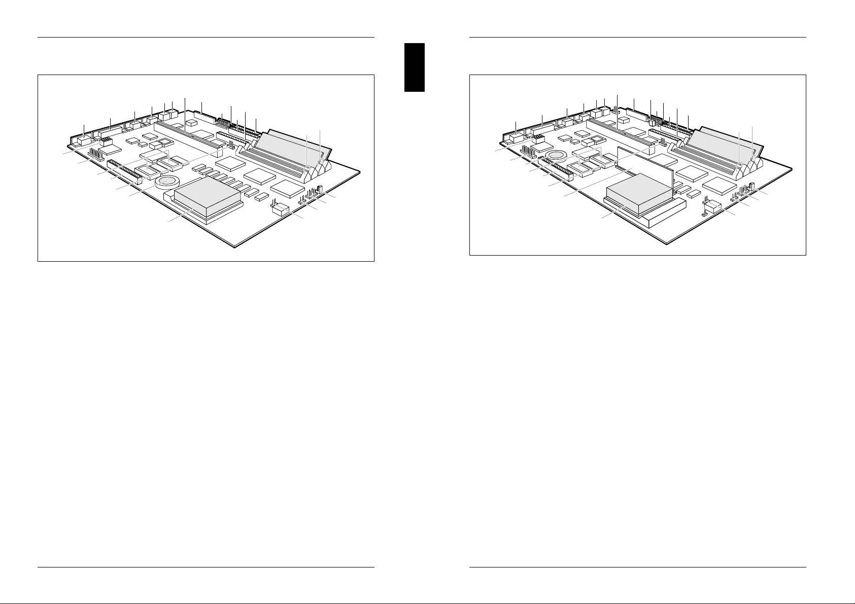
System board D841
7
6
5
4
3
2
1
8
10
12
9
11
13
14
15
26
25
24
23
22
21
20
1 = Monitor interface 14 = Location bank 1 for main memory
2 = Parallel interface 15 = Location bank 0 for main memory
3 = Serial interface (Ser 2) 16 = Connector for soft-off power switch
4 = Serial interface (Ser 1) 17 = Connector for LED indicators
5 = PS/2 mouse interface 18 = Connector for external
6 = PS/2 keyboard port loudspeaker
7 = Bus interface 19 = Socket for processor fan
8 = Connector for power supply 5 V 20 = Processor with heat sink
9 = Connector for power supply 3.3 V 21 = Lithium battery
10 = Connector for soft-off power supply 22 = Connector for LED indicator of
11 = Connector 1 for IDE drives 1 and 2 SCSI hard disk drive
(e.g. hard disk drive) 23 = Imageport connector
12 = Connector 2 for IDE drives 3 and 4 24 = Sockets for video memory
13 = Connector for 25 = Connector for external monitor
floppy disk drive controller
(VESA VGA Pass-Through)
26 = Switch block
19
18
17
16
System board D842
7
6
5
4
3
2
1
8
9
11
13
10
12
14
15
16
28
27
26
25
24
23
19
18
17
22
21
1 = Monitor interface 15 = Location bank 1 for main memory
2 = Parallel interface 16 = Location bank 0 for main memory
3 = Serial interface (Ser 2) 17 = Connector for soft-off power switch
4 = Serial interface (Ser 1) 18 = Connector for LED indicators
5 = PS/2 mouse interface 19 = Connector for external
6 = PS/2 keyboard port loudspeaker
7 = Bus interface 20 = Socket for processor fan
8 = Connector for power supply 5 V 21 = Processor with heat sink
9 = Connector for remote power-on 22 = Voltage converter
10 = Connector for power supply 3.3 V 23 = Connector for LED indicator of
11 = Connector for soft-off power supply SCSI hard disk drive
12 = Connector 1 for IDE drives 1 and 2 24 = Imageport connector
(e.g. hard disk drive) 25 = Sockets for video memory
13 = Connector 2 for IDE drives 3 and 4 26 = Lithium battery
14 = Connector for 27 = Connector for external monitor
floppy disk drive controller
(VESA VGA Pass-Through)
28 = Switch block
20
A26361-D841-Z121-4-7619 3
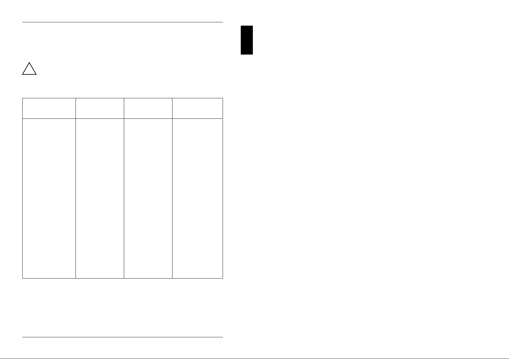
Possible screen resolution
The screen resolutions in the following table refer to the monitor controller on the
system board.
If you are using an external monitor controller, you will find details of supported
screen resolutions in the Operating Manual or Technical Manual supplied with the
controller.
4 A26361-D841-Z121-4-7619
Page 7
Introduction
You can use the REFRATE program (under Windows 95), the WDSETUP program
(under MS-Windows) or the SET-VGA program (under MS-DOS) to set the screen
resolution. Detailed information is provided in the corresponding help.
You may set only those resolutions and refresh rates specified in the
"Technical data" section of the monitor description. Otherwise you may
!
damage your monitor. If you are in any doubt, contact your sales office or
customer service.
Screen Refresh Horizontal Max. number
resolution rate (Hz) rate (kHz) of colors
640x350 70 31,5 16
640x350 84 38 16
640x480 60 31,5 16777216
640x480 75 38 16777216
640x480 90 48 65536
720x400 70 31,5 16
720x400 84 38 16
800x600 56 35 16777216 *)
800x600 56 35 65536
800x600 60 38 16777216 *)
800x600 60 38 65536
800x600 75 47 65536
800x600 90 60 256
1024x768 87 interlaced 36 65536 *)
1024x768 87 interlaced 36 256
1024x768 60 49 65536 *)
1024x768 60 49 256
1024x768 70 57 256
1024x768 75 60 256
1280x1024 87 interlaced 49 256 *)
1280x1024 87 interlaced 49 16
1280x1024 60 64 256 *)
1280x1024 75 80 256 *)
*) Only with 2 Mbyte of video memory
A26361-D841-Z121-4-7619 5
Page 8
Important notes
Important notes
Be sure to read this page carefully and note the information before you
open the PC.
!
Please note the information provided in the chapter "Safety" in the
Operating Manual of the PC.
Incorrect replacement of the lithium battery may lead to a risk of explosion.
It is therefore essential to observe the instructions in the section "Add-on
modules - Replacing the lithium battery".
The lithium battery must be replaced with an identical battery or a battery
type recommended by the manufacturer (CR2032).
Do not throw lithium batteries into the trashcan. Your vendor or dealer or
their authorized representatives will take used batteries back free of charge
so that they can be recycled or disposed of in the proper manner.
ADVARSEL
Lithiumbatteri - Eksplosionsfare ved fejlagtig håndtering. Udskiftning må kun
ske med batteri af samme fabrikat og type. Lever det brugte batteri tilbage
!
til leverandøren.
ADVARSEL
Eksplosjonsfare ved feilaktig skifte av batteri. Benytt samme batteritype eller
en tilsvarende type anbefalt av apparatfabrikanten. Brukte batterier
!
kasseres i henhold til fabrikantens instruksjoner.
VARNING
Eksplosionsfara vid felaktigt batteribyte. Använd samma batterityp eller en
ekvivalent typ som rekommenderas av apparattillverkarenfabrikanten.
!
Kassera använt batteri enligt fabrikantens instruktion.
VAROITUS
Paristo voi räjähtää, jos se on virheellisesti asennettu. Vaihda paristo
ainoastaan laitevalmistajan suosittelemaan tyyppiin. Hävitä käytetty paristo
!
valmistajan ohjeiden mukaisesti.
Modules with electrostatic sensitive devices (ESD) may be identified by labels.
When you handle modules fitted with ESDs, you must observe the following points
under all circumstances:
– When you handle modules fitted with ESDs, you must always discharge yourself
(e.g. by touching a grounded object) before working.
– The equipment and tools you use must be free of static charges.
– Pull out the power plug before inserting or pulling out modules containing ESDs.
– Always hold modules with ESDs by their edges.
– Never touch pins or conductors on modules fitted with ESDs.
Notes on software
Program with time loops
Problems can occur with programs in which time loops have been implemented
through software loops. This applies in particular to older programs which were
written for 8 MHz processors.
SCO-UNIX on devices with pentium or OverDrive processor
If you upgrade the system board by adding a processor mentioned above, please
note the following:
If you use the processor mentioned above, the Adaptec-SCSI controller cannot be
addressed under SCO-UNIX 3.2.4 and ODT 2.0.
To solve this problem, you can order from SCO a set of SLS (Support Level
Supplement) floppies (consisting of 3 floppy disks) under the number uod361,
free of charge, or contact
The problem no longer exists in the new releases of SCO-UNIX 3.2.4.2 and
ODT 2.1.
There will be no support for older versions (SCO-UNIX versions lower than 3.2.4
and ODT versions lower than 2.0).
one of our IT Service Shops.
A26361-D841-Z121-4-7619 7
8 A26361-D841-Z121-4-7619
Page 9
Settings
Settings
You can make settings in the setup menu or using the switch block on the system
board. The system board D842 has additional jumpers.
Setup menu
The setup menu displays settings and technical information on the PC's
configuration. The Operating Manual describes how to call the setup menu and
change menu entries. Pressing the function key
each entry field.
The setup menu consists of the following screen pages:
System Configuration
System Security Options
Additional System Options
PCI Device Configuration
Additional Hard Disk Options
Power Management Configuration
F1 provides help information on
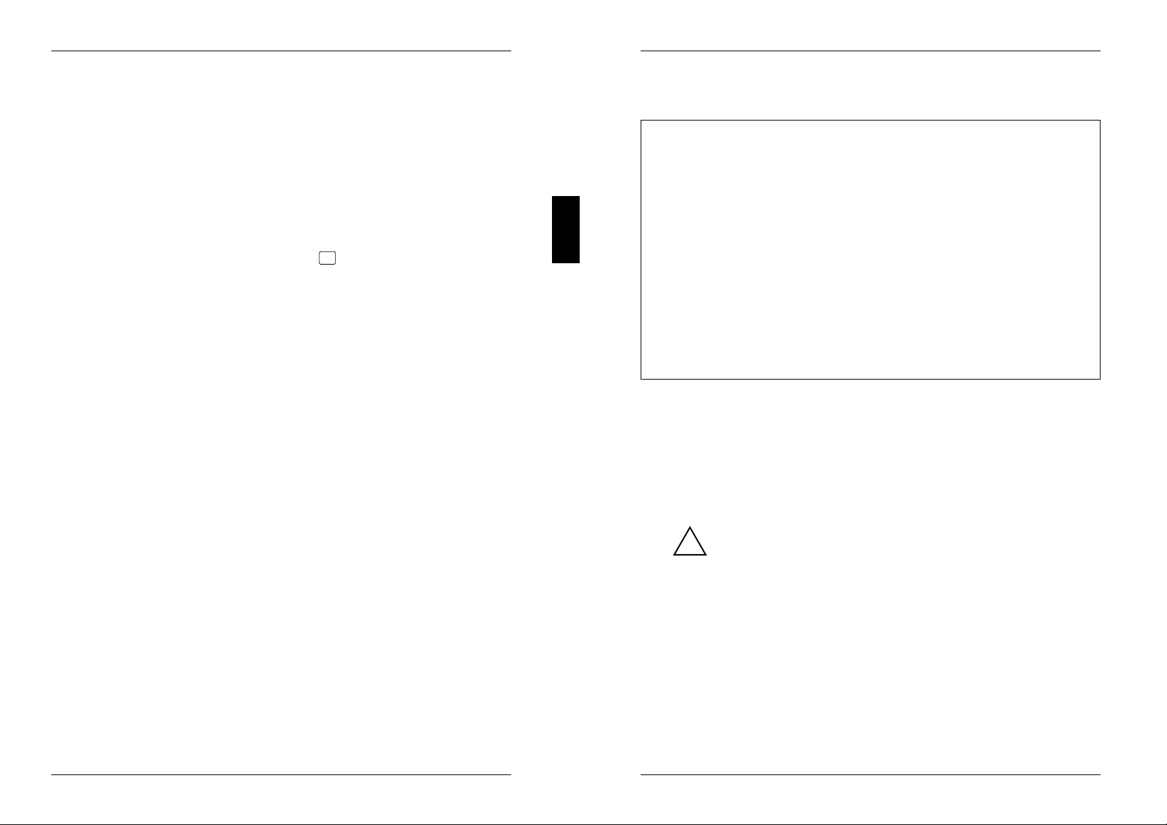
System Configuration page
CMOS Setup
System Configuration
--------------------------------------------------------------------------Time (hh:mm:ss) 08:38:27 Date (mm/dd/yy) 08/13/1993
Diskette A: 1.4M
Diskette B: NONE
Cyl Hd Pre LZ Sec Mbyte
Hard Disk 1: NONE
Hard Disk 2: NONE
Hard Disk 3: NONE
Hard Disk 4: NONE
Base Memory: 640K Video Display: EGA/VGA
Extended Memory: 15360K Speed Select: HIGH
Error Halt: HALT ON ALL ERRORS
--------------------------------------------------------------------------<F1> Help <F8> System info <F10> Store CMOS <Esc> Exit Page
<...> Edit field <↑↓←→> Next field <PgUp> Next page <Ctrl> ... 01
Example of the System Configuration page
Time
Date
The Time field and the Date field show the time and date respectively
according to the PC. The time is shown in the format hh:mm:ss
(hours:minutes:seconds) and the date is shown in the format mm/dd/yy
(month/day/year).
A26361-D841-Z121-4-7619 9
If the settings in the Time and Date fields are frequently wrong when
you power up the computer, the lithium battery is dead. Change the
!
battery as described in "Add-on modules - Replacing the lithium
battery").
Diskette A
Diskette B
These two fields are used to specify the type of floppy disk drive installed.
The possible settings are: 360K, 1.2M, 720K, 1.4M, 2.8M or NONE.
Default entry for Diskette A:
3 1/2-inch floppy drive 1.4M
5 1/4-inch floppy drive 1.2M
Default entry for Diskette B: NONE
10 A26361-D841-Z121-4-7619
Page 10

Settings
Settings
Hard Disk 1
Hard Disk 2
Hard Disk 3
Hard Disk 4
These fields are used to indicate the types of hard disks installed. The entries
here may possibly not match the information printed on the hard disk drive by
the manufacturer.
The maximum transfer rate of two IDE drives connected to the same
connector is determined by the slower of the two. Fast hard disks should
therefore be connected to the first IDE connector and identified as Hard
Disk 1 or Hard Disk 2; slower hard disks should be connected to the second
IDE connector and identified as Hard Disk 3 or Hard Disk 4.
Possible settings: 1 through 43, AUTO or NONE.
Do not alter the default settings unless you mount a different hard disk
i
drive. If the wrong hard disk type is entered, the operating system
cannot be loaded.
Special entries for the hard disk type:
Entry for SCSI hard disks: NONE
Entry for ESDI hard disks: 1
1 through 39
The hard disk parameters (cylinders, heads, etc.) for types 1 through 39
are preset.
40 through 43
The hard disk parameters (cylinders, heads, etc.) for types 40 through 43
are user-defined and are entered at the keyboard.
AUTO
If the hard disk supports this mode, the setup menu reads the hard disk
parameters from the disk itself and sets them automatically. You do not
need to select the parameters yourself.
NONE
The computer either has no hard disk or is fitted with a SCSI hard disk.
Default entry for Hard Disk 1:
depends on the type of hard disk installed
Default entry for Hard Disk 2, 3, 4: NONE
Base Memory
This field indicates the size of the available base memory below 1 Mbyte.
512K
A module needs the memory between 512 and 640 Kbyte.
640K
The memory is used by the system board.
Default entry: 640K
Extended Memory
This field indicates the size of the memory above 1 Mbyte. You can reduce
the size of extended memory if necessary.
Video Display
This field is used to specify the type of monitor connected.
Possible entries are: EGA/VGA, COLOR 40, COLOR 80, MONO.
Default entry: EGA/VGA
Examples of user-defined entries (IDE drives)
Size Cyl Hd Pre* Lz* Sec Mbyte
120 Mbyte: 762 8 NONE 762 39 121
170 Mbyte: 904 8 NONE 904 46 170
210 Mbyte: 683 16 NONE 683 38 212
340 Mbyte: 904 16 NONE 904 46 340
540 Mbyte: 1048 16 NONE 1048 63 542
1 Gbyte: 2079 16 NONE 2079 63 1080
* These values are preset and cannot be modified.
In LBA mode different values may be displayed here.
i
A26361-D841-Z121-4-7619 11
Speed Select
This field is used to specify the system speed set at system startup. You
might, for example, need to select a slower speed for certain software
programs that use programmed time loops.
HIGH
Full system speed
LOW
Reduced system speed.
Default entry: HIGH
12 A26361-D841-Z121-4-7619
Page 11
Settings
Settings
Error Halt
This field is used to specify which errors the self-test should not report. The
default setting should only be changed if required by special applications.
HALT ON ALL ERRORS
The self-test reports all errors it encounters.
NO KEYBOARD ERROR HALT
The self-test ignores keyboard errors.
NO DISK ERROR HALT
The self-test ignores floppy disk and hard disk errors.
NO KEYBOARD OR DISK HALT
The self-test ignores keyboard, floppy disk and hard disk errors.
NO HALT ON ANY ERRORS
The self-test ignores all errors.
Default entry: HALT ON ALL ERRORS
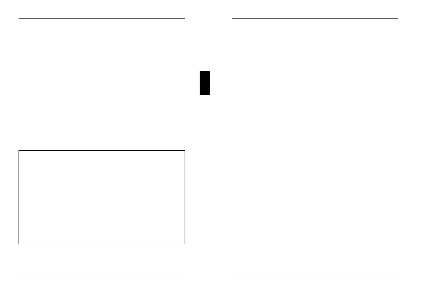
The System Security Options page
CMOS Setup
System Security Options
--------------------------------------------------------------------------Time (hh:mm:ss) 08:38:27 Date (mm/dd/yy) 08/13/1993
System Load: STANDARD
Security Features: DISABLED
Serial 1: COM1 (3F8h) Diskette Write: ENABLED
Serial 2: COM2 (2F8h) Diskette Ctrlr: ENABLED
Parallel: LPT1 (378h) Setup Prompt: ENABLED
Par Mode: PRINTER Quick Load: DISABLED
Virus Warning: DISABLED
Mouse Ctrlr ENABLED
Flash Write: ENABLED
--------------------------------------------------------------------------<F1> Help <F8> System info <F10> Store CMOS <Esc> Exit Page
<+ -> Select item <↑↓←→> Next field <PgUp> Next page <Ctrl> ... 02
date according to the PC.
System Load
This field allows you to disable booting from floppy disk or swap the drive
letters assigned to the floppy disk drives.
STANDARD
The operating system can be loaded from floppy disk or hard disk.
NONSTANDARD
System start-up is controlled by the operating system (terminal
emulation).
DISKETTE LOCK
The operating system can only be loaded from hard disk.
DISKETTE SWAP
Drives A and B are switched.
Default entry: STANDARD
Security Features
This field allows you to define a password to prevent access to the data in
your PC.
DISABLED
No passwords are in effect.
SYSTEM AND SETUP LOCK
The setup menu and the operating system are protected by passwords.
SETUP LOCK
The setup menu is protected by a password.
KEYBOARD AND SETUP LOCK
The setup menu is protected and the keyboard and the mouse are locked
by passwords.
CHANGE PASSWORD
This option is only displayed if a password has already been defined. It
enables you to alter the password.
Default entry: DISABLED
Example of the System Security Options page
Time / Date
The Time field shows the current time and the Date field shows the current
A26361-D841-Z121-4-7619 13
14 A26361-D841-Z121-4-7619
Page 12

Settings
Settings
Serial 1
The address and the interrupt used to access serial interface 1 are selected
here.
COM1 (3F8h)
Serial interface 1 is set to the address 3F8h and IRQ4 (edge-triggered).
COM3 (3E8h)
Serial interface 1 is set to the address 3E8h and IRQ4 (edge-triggered).
DISABLED
Serial interface 1 is disabled.
Default entry: COM1 (3F8h)
Serial 2
The address and the interrupt used to access serial interface 2 are selected
here.
COM2 (2F8h)
Serial interface 2 is set to the address 2F8h and IRQ3 (edge-triggered).
COM4 (2E8h)
Serial interface 2 is set to the address 2E8h and IRQ3 (edge-triggered).
DISABLED
Serial interface 2 is disabled.
Default entry: COM2 (2F8h)
Parallel
The address and the interrupt used to access the parallel interface are
selected here.
LPT1 (378h)
The parallel interface is set to the address 378h and IRQ7.
LPT2 (278h)
The parallel interface is set to the address 278h and IRQ5.
LPT3 (3BCh)
The parallel interface is set to the address 3BCh and IRQ7.
DISABLED
The parallel interface is disabled.
Default entry: LPT1 (378h)
Par Mode
This field is used to specify whether the parallel interface is to be used as a
bidirectional input/output port or just as an output port.
In addition, LPT1 and LPT2 can be configured for ECP, EPP, and ECP and
EPP transfer modes, which allow transfer rates of 2 and 2.4 Mbyte/s. These
modes will only work with peripheral devices which also support them.
PRINTER
The port functions as an output port only.
BIDIRECTION
Data can be transferred in both directions across the port.
EPP
Enhanced Parallel Port transfer mode.
ECP
Enhanced Capability Port transfer mode.
ECP AND EPP
Enhanced Capability and Enhanced Parallel Port transfer mode.
Default entry: PRINTER
Mouse Ctrlr
This field is used to enable and disable the built-in mouse controller on the
system board.
ENABLED
The mouse controller is enabled (IRQ12 used).
DISABLED
The mouse controller is disabled (IRQ12 free).
Default entry: ENABLED
Flash Write
This field is used to write-protect the flash BIOS.
ENABLED
The flash BIOS can be written or deleted, provided switch 3 on the system
board is set to OPEN.
DISABLED
The flash BIOS cannot be written. The BIOS cannot be flash-upgraded
from floppy disk.
Default entry: ENABLED
A26361-D841-Z121-4-7619 15
16 A26361-D841-Z121-4-7619
Page 13

Settings
Settings
Diskette Write
This field is used to enable and disable floppy disk write-protection.
ENABLED
Floppy disks can be read, written or deleted, provided switch 4 on the
system board is set to OPEN.
DISABLED
Floppy disks can only be read.
Default entry: ENABLED
Diskette Ctrlr
This field is used to enable and disable the built-in floppy disk controller on
the system board.
ENABLED
The floppy disk controller is enabled.
DISABLED
The floppy disk controller is disabled.
Default entry: ENABLED
Setup Prompt
This field specifies whether the F2 FOR SETUP prompt is displayed when
the PC is started.
ENABLED
The F2 FOR SETUP prompt is displayed when the system is started.
DISABLED
The prompt is not displayed.
Default entry: ENABLED
Quick Load
This field allows you to shorten the duration of the self-test and speed up
system start-up. If you choose the quick self-test option, only a minimum
memory test is carried out.
ENABLED
The quick self-test is enabled.
DISABLED
The normal self-test is carried out.
Default entry: DISABLED
Virus Warning
This field enables and disables a check of the boot sector on the bootable
hard disk for changes since the last system start-up. If changes are detected
and the cause is unknown, you should run an appropriate virus checker to
check for a virus.
ENABLED
If the boot sector has been modified since the system last booted (e.g,. a
new operating system version has been installed or the hard disk has
been infected by a virus), an on-screen warning appears.
!!! HARD DISK WARNING !!!
Boot sector has been modified.
Confirm the new boot sector in SETUP,
and run a virus scan program.
This warning is re-displayed each time you restart the system until you
acknowledge the message with CONFIRM or you disable the function by
setting this field to DISABLED.
CONFIRM
By selecting this option, you indicate to the system that the modification to
the boot sector was intentional (e.g., you have installed a new operating
system version).
A26361-D841-Z121-4-7619 17
DISABLED
Boot sectors are not checked.
Default entry: DISABLED
18 A26361-D841-Z121-4-7619
Page 14
Settings
Settings
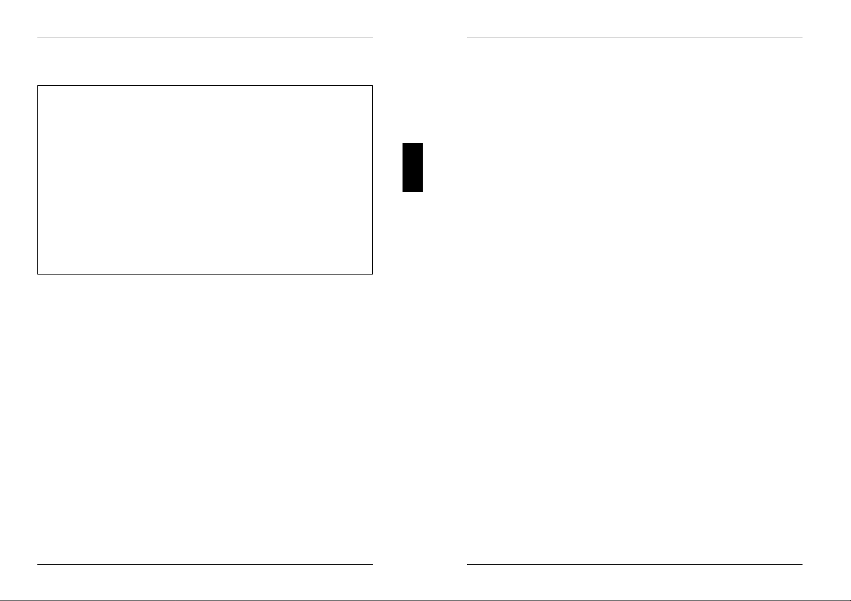
Additional System Options page
CMOS Setup
Additional System Options
--------------------------------------------------------------------------Time (hh:mm:ss) 08:38:27 Date (mm/dd/yy) 08/13/1993
System BIOS: 128K
Shadow BIOS ROM: SYSTEM AND VIDEO BIOS
C800 CC00 D000 D400 D800 DC00
Shadow Adaptor ROM: NO NO NO NO NO NO
Cache: INTERN AND EXTERN
Cache Mode: WRITE BACK
Cache BIOS ROM: VIDEO BIOS ONLY
C800 CC00 D000 D400 D800 DC00
Cache Adaptor ROM: NO NO NO NO NO NO
--------------------------------------------------------------------------<F1> Help <F8> System info <F10> Store CMOS <Esc> Exit Page
<+ -> Select item <↑↓←→> Next field <PgUp> Next page <Ctrl> ... 03
Example of the Additional System Options page
Time / Date
The Time field shows the current time and the Date field shows the current
date according to the PC.
System BIOS
In this field you can make available a ROM address area of 32 Kbytes for
requests via the ISA/PCI bus (e.g., SCSI BIOS).
96K
A 96-Kbyte area (E8000H - FFFFFH) is reserved for the system BIOS.
A 32-Kbyte area (E0000H - E7FFFH) is available for requests via the
ISA/PCI bus.
128K
A 128-Kbyte area (E0000H - FFFFFH) is reserved for the system BIOS.
Default entry: 128K
Shadow BIOS ROM
This field allows you to copy the video BIOS to fast RAM in addition to the
system BIOS at system start-up. Copying the BIOS to RAM increases CPU
performance.
SYSTEM AND VIDEO BIOS
The system BIOS and the video BIOS are both copied to RAM area
C0000H - C7FFFH (video BIOS) and F0000H - FFFFFH (system BIOS).
SYSTEM BIOS ONLY
Only the system BIOS is copied to RAM area E8000H - FFFFFH.
Default entry: SYSTEM AND VIDEO BIOS
Shadow Adaptor ROM
This field allows you to copy 16-Kbyte adaptor ROMs to RAM. If ROM code
executes from RAM it increases your PC's performance. The ROM of PCI
adaptors is always copied to RAM, regardless of the setting in this field.
NO
The relevant ROM area is not copied to RAM.
YES
The relevant ROM area is copied to RAM.
Default entry: NO
Cache
This field is used to specify which cache memory the CPU should use.
Cache memory greatly increases performance. If the system runs too fast for
certain older software, you can slow it down by disabling the cache
(DISABLED).
INTERN ONLY
Only the internal cache is enabled.
INTERN AND EXTERN
The internal cache and the external cache are enabled.
DISABLED
Both the internal cache and the external cache are disabled. All cacherelated settings are then without effect.
A26361-D841-Z121-4-7619 19
Default entry: INTERN AND EXTERN
20 A26361-D841-Z121-4-7619
Page 15
Settings
Settings
Cache Mode
Condition: Cache must be enabled.
Cache Mode sets the mode in which the CPU uses the cache; write
operations to the cache are carried out either in write-back mode or writethrough mode. In write-back mode the CPU writes information to the cache
and the information is only written to main memory if necessary. Memory and
cache contents are not identical. In write-through mode the processor writes
the information to the cache and to main memory. The contents of memory
and cache are identical.
WRITE BACK
The cache works in write-back mode.
WRITE THROUGH
The cache works in write-through mode.
Default entry: WRITE BACK
Cache BIOS ROM
Condition: Cache must be enabled.
Cache BIOS ROM lets you specify BIOS ROM areas that should also be
mapped to the cache in addition to main memory.
SYSTEM BIOS ONLY
The system BIOS is mapped to the cache.
VIDEO BIOS ONLY
The video BIOS is mapped to the cache.
Cache Adaptor ROM
Condition: Cache must be enabled.
Cache Adaptor ROM allows you to specify whether the relevant 16-Kbyte ROM
area should be mapped to the cache. Mapping the ROM area to RAM
increases system performance.
NO
The relevant ROM area is not mapped to the cache.
YES
The relevant ROM area is mapped to the cache.
Default entry: NO
PCI Device Configuration page
CMOS Setup
PCI Device Configuration
--------------------------------------------------------------------------Time (hh:mm:ss) 08:38:27 Date (mm/dd/yy) 08/13/1993
Memory Base Address: 44000000h Color Palette Snoop: DISABLED
I/O Base Address: D000h Parity Checking: ENABLED
INTA# INTB# INTC# INTD#
PCI Interrupt Mapping: AUTO AUTO AUTO AUTO
SYSTEM AND VIDEO BIOS
The system BIOS and the video BIOS are mapped to the cache.
DISABLED
BIOS ROM areas are not mapped to the cache.
Default entry: SYSTEM AND VIDEO BIOS
A26361-D841-Z121-4-7619 21
--------------------------------------------------------------------------<F1> Help <F8> System info <F10> Store CMOS <Esc> Exit Page
<...> Select item <↑↓←→> Next field <PgUp> Next page <Ctrl> ... 04
Example of the PCI Device Configuration page
Time / Date
The Time field shows the current time and the Date field shows the current
date according to the PC.
Memory Base Address
This field shows the base address used to map memory areas of PCI boards.
22 A26361-D841-Z121-4-7619
Page 16
Settings
Settings
I/O Base Address
This field shows the base address for PCI adapter input/output operations.
Color Palette Snoop
This field is used to specify whether setting of the color palette is to be
available on the ISA bus.
ENABLED
Setting of the color palette is available simultaneously on the PCI bus and
the ISA bus. This setting can be of relevance when operating video or
multimedia boards on the ISA bus.
DISABLED
Setting of the color palette is only available on the PCI bus.
Default entry: DISABLED
Parity Checking
Here you specify whether the PCI bus is to be parity-checked.
ENABLED
A parity check is performed on the PCI bus.
DISABLED
No parity check is performed on the PCI bus.
Default entry: ENABLED
PCI Interrupt Mapping
Here you specify which PCI interrupt is to be mapped to which ISA interrupt.
With multifunctional PCI adaptor boards you may use all PCI interrupts.
If you need ISA interrupts you must set the unused PCI interrupts to NONE.
The onboard controllers connected to PCI bus do not use any PCI interrupt.
The PCI interrupts INTA# and INTB# are normally assigned as follows:
PCI slot 1 = INTA#, PCI slot 2 = INTB#
Possible entries: NONE, AUTO, 3, 4, 5, 6, 7, 9, 10, 11, 12, 14, 15
Default entry: INTA# AUTO
INTB# AUTO
INTC# AUTO
INTD# AUTO
Additional Hard Disk Options page
CMOS Setup
Additional Hard Disk Options
--------------------------------------------------------------------------Time (hh:mm:ss) 08:38:27 Date (mm/dd/yy) 08/13/1993
Hard Disk Ctrlr: ENABLED
Transfer Mode LBA Translation Power Down
Hard Disk 1: STANDARD DISABLED DISABLED
Hard Disk 2: STANDARD DISABLED DISABLED
Hard Disk 3: STANDARD DISABLED DISABLED
Hard Disk 4: STANDARD DISABLED DISABLED
--------------------------------------------------------------------------<F1> Help <F8> System info <F10> Store CMOS <Esc> Exit Page
<+ -> Select item <↑↓←→> Next field <PgUp> Next page <Ctrl> ... 05
Example of the Additional Hard Disk Options page
Time / Date
The Time field shows the current time and the Date field shows the current
date according to the PC.
Hard Disk Ctrlr
This fields allows you to enable and disable the built-in IDE hard disk
controller. The associated interrupt will only be available if no hard disk is
physically connected.
ENABLED
The IDE hard disk controller is enabled.
DISABLED
The IDE hard disk controller is disabled.
Default entry: ENABLED
A26361-D841-Z121-4-7619 23
24 A26361-D841-Z121-4-7619
Page 17

Settings
Settings
Hard Disk 1: Transfer Mode
Hard Disk 2: Transfer Mode
Hard Disk 3: Transfer Mode
Hard Disk 4: Transfer Mode
Here you specify the transfer rate for the IDE hard disks.
STANDARD
The system transfers 512 bytes per interrupt
AUTO SELECT
If fast hard disks are installed, the highest possible transfer rate is
selected. If the hard disk supports this mode, the setup menu prompts for
the maximum number of blocks to be transferred per interrupt. The
maximum is 32 blocks of 512 bytes each. In addition, the hard disk's PIO
modes 0 through 4 (Processor Input Output modes) are used.
8K BLOCK XFER
Eight Kbytes are transferred per interrupt.
Default entry: STANDARD
Hard Disk 1: LBA Translation
Hard Disk 2: LBA Translation
Hard Disk 3: LBA Translation
Hard Disk 4: LBA Translation
This field enables and disables the LBA (Logical Block Addressing) mode.
LBA mode allows you to install and use hard disks with a capacity of more
than 528 Mbytes. If a hard disk supports LBA mode, you can use its full
capacity.
AUTO SELECT
If the hard disk supports LBA and it has a capacity of more than 528
Mbytes, the BIOS translates the hard disk parameters, allowing the disk's
full capacity to be used.
If the hard disk does not support LBA, its parameters are not translated.
Default entry: depends on the hard disk type installed
Hard Disk 1: Power Down
Hard Disk 2: Power Down
Hard Disk 3: Power Down
Hard Disk 4: Power Down
Here you specify the period of hard disk inactivity after which the hard disk's
motor is power down. The next hard disk read or write operation powers up
the hard disk again automatically.
The hard disk requires roughly 15 seconds to run up.
Possible entries: DISABLED, 5 min, 10 min, 15 min
Default entry: DISABLED (the hard disk does not power down)
You may only use IDE drives in the LBA mode selected when they
were set up. In other words, if you set up a hard disk with LBA mode
!
DISABLED, you may only operate the hard disk with LBA mode
DISABLED.
DISABLED
The BIOS uses the hard disk parameters and supports a maximum
capacity of 528 Mbytes.
A26361-D841-Z121-4-7619 25
26 A26361-D841-Z121-4-7619
Page 18
Settings
Settings
Power Management Configuration page
CMOS Setup
Power Management Configuration
--------------------------------------------------------------------------Time (hh:mm:ss) 08:38:27 Date (mm/dd/yy) 08/13/1993
Standby Timeout: DISABLED Wakeup Timer: 00:00:00
Standby Function Wakeup Event
Video: ENABLED System Tic: DISABLED
Hard Disk: ENABLED Mouse: ENABLED
CPU Speed: LOW IRQ09: DISABLED
Hard Disk 4: STANDARD IRQ10: DISABLED
IRQ11: DISABLED
--------------------------------------------------------------------------<F1> Help <F8> System info <F10> Store CMOS <Esc> Exit Page
<+ -> Select item <↑↓←→> Next field <PgUp> Next page <Ctrl> ... 06
Example of the Power Management Configuration page
Time / Date
The Time field shows the current time and the Date field shows the current
date according to the PC.
Standby Timeout
Here you specify the period of inactivity after which the system switches to
standby mode.
Possible entries: DISABLED, 1 min, 2 min, 5 min, 10 min, 15 min, 30 min, 60 min
Default entry: DISABLED (the system does not switch to standby mode)
Wakeup Timer
Here you specify the time at which the system returns to its normal operating
mode from standby mode.
DISABLED
The monitor remain switched on.
ENABLED
The monitor is switched off.
Default entry: ENABLED
Hard Disk
Here you enable and disable the hard disk controller's standby mode.
DISABLED
The hard disk controller remains on.
ENABLED
The hard disk controller shuts itself down.
Default entry: ENABLED
CPU Speed
System board D841:
This field is always set to HIGH.
System board D842:
This field allows you to specify the CPU speed in standby mode.
HIGH
The CPU runs at the highest clock speed.
REDUCED
The CPU runs at a reduced clock speed.
LOW
The CPU runs at the lowest clock speed.
STOPPED
The CPU stops. This mode saves the most power. However, any
programs running are also placed in standby mode.
Default entry: HIGH
Default entry: 00:00:00 (the function is disabled)
Standby Function
Video
This field allows you to enable and disable the video controller's standby
function. You should only enable this function if both video controller and
display support the power-saving function.
A26361-D841-Z121-4-7619 27
Wakeup Event
This field defines the source of the wakeup event that switches the system back
into its normal operating mode from standby mode.
Certain wakeup events only return the system board to its normal operating
i
mode, but not the display.
28 A26361-D841-Z121-4-7619
Page 19
Settings
Settings
System Tic
You should only use this option in connection with special applications. The
System Tic-Modus generates an interrupt every 55 ms and would normally
cause the system to return instantly to its normal operating mode.
DISABLED
The System Tic is ignored.
ENABLED
The System Tic switches the system board back to its normal operating
mode.
Default entry: DISABLED
Mouse
Condition:
The mouse must be connected to the PS/2 mouse port.
DISABLED
Mouse movement is ignored.
ENABLED
Moving the mouse switches the system back into its normal operating
mode.
Default entry: ENABLED
IRQ09
IRQ10
IRQ11
All hardware interrupts not included here always switch the system board
back to its normal operating mode. The hardware interrupts IRQ1 (keyboard),
IRQ3 and IRQ4 also reactivate the display.
DISABLED
The relevant hardware interrupt is ignored.
ENABLED
The relevant hardware interrupt switches the system board back to its
normal operating mode.
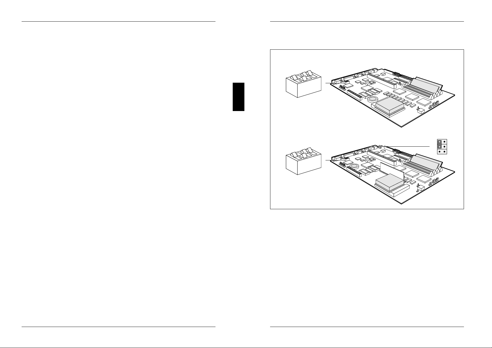
Switch block and jumper
D841
4
3
2
1
ON
D842
1
N
O
Switch 1 = BIOS recovery X507 = Jumper for keyboard and
Switch 2 = Service pointing device
Switch 3 = BIOS update
Switch 4 = Floppy disk write-protection
Switch 2 must always be set to OPEN.
N
E
P
O
4
3
2
N
E
P
O
1
3
5
X507
2
4
6
Default entry: DISABLED
A26361-D841-Z121-4-7619 29
30 A26361-D841-Z121-4-7619
Page 20

Settings
Settings
BIOS recovery
Switch 1 enables recovery of the old BIOS after an attempt to update it has failed.
To restore the old BIOS you need a recovery disk (call customer service).
If BIOS recovery is possible, the BIOS executes from floppy drive A: and restores
the flash BIOS.
BIOS recovery = switch 1 set to ON
Normal operation = switch 1 set to open
Default setting:
Switch 1 set to open = normal operation
BIOS update
If you wish to update your system BIOS, please consult customer service.
i
Switch 3 enables and disables BIOS updating. In addition, when updating the BIOS
you must ensure that Flash Write is set to ENABLED in the System Security Options
setup menu.
BIOS updating disabled = switch 3 set to ON
BIOS updating enabled = switch 3 set to OPEN
Default setting:
Switch 3 set to OPEN = BIOS updating enabled
Keyboard and pointing device
The setting of jumper X507 on the system board D842 depends on which keyboard
or pointing device you want to use.
Keyboard (with/without power switch) and mouse = jumper is set to 1-3 and 4-6
Keyboard (without power switch, with integrated trackball) =
jumper is set to 3-5 and 2-4
Keyboard (without power switch, with integrated trackball) and mouse =
jumper is set to 1-3
Default setting:
depends on the type of keyboard and pointing device used
External cache
The system board is equipped with 256 Kbytes of external cache. To ensure
optimum benefit from the external cache, make the following settings in the setup
menu:
– Speed Select: HIGH
– Shadow BIOS ROM: SYSTEM AND VIDEO BIOS
– Cache: INTERN AND EXTERN
– Cache BIOS ROM: SYSTEM AND VIDEO BIOS
Write protection for floppy disk drive
Switch 4 is used to define whether floppy disks can be written or deleted in the
floppy disk drive. To write and delete floppy disks, the field Diskette Write must be
set to ENABLED in the System Security Options setup menu.
Read only floppy disks = switch 4 is set to ON
Read, write and delete floppy disks = switch 4 is set to OPEN
Default setting:
Switch 4 is set to OPEN = read, write and delete floppy disks enabled
A26361-D841-Z121-4-7619 31
32 A26361-D841-Z121-4-7619
Page 21
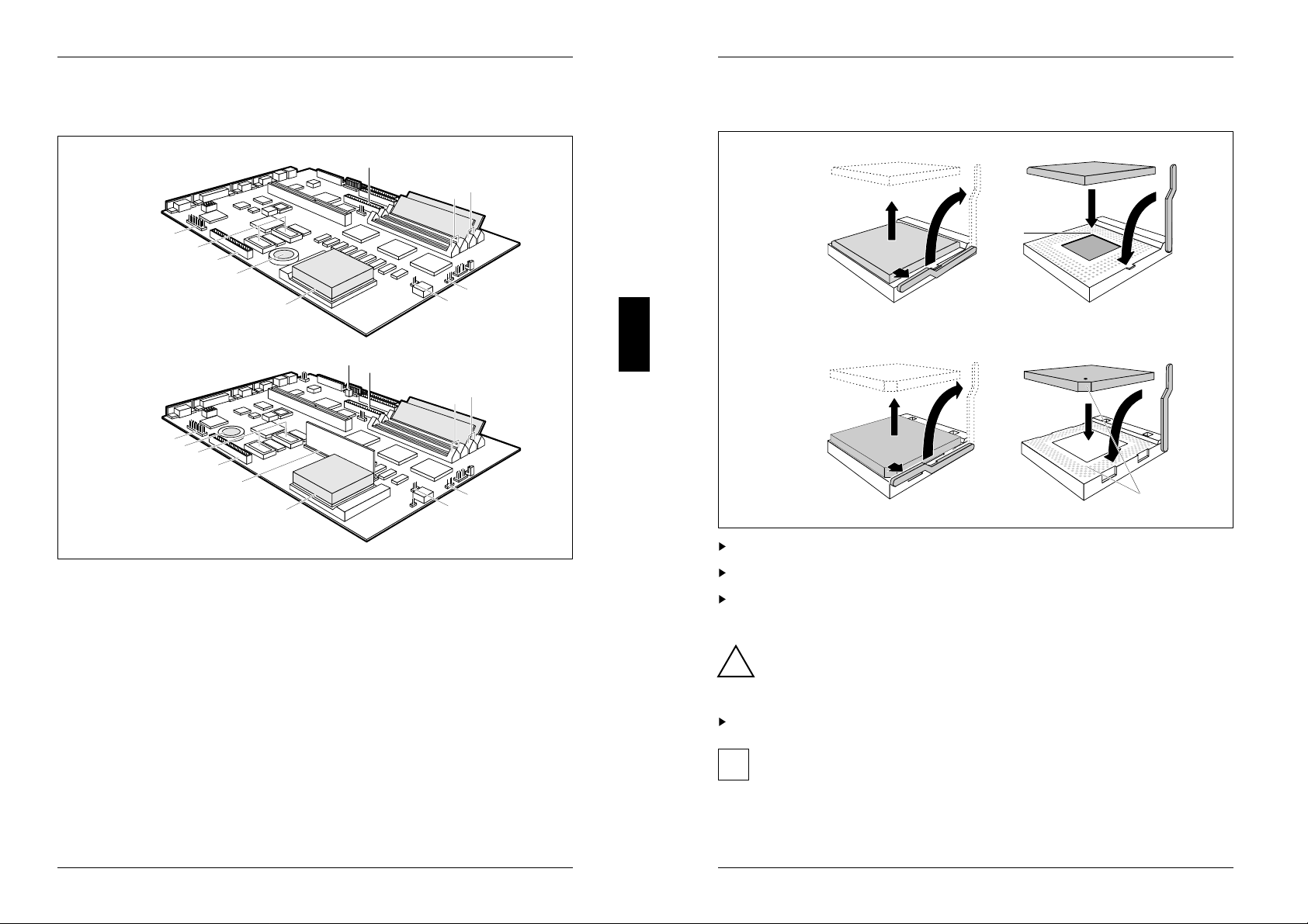
Add-on modules
Add-on modules
D841
10
9
8
7
6
D842
l
k
j
i
h
g
1 = Connector 2 for IDE drives 3 and 4 a = Connector remote power-on
2 = Location bank 1 for main memory b = Connector 2 for IDE drives 3 and 4
3 = Location bank 0 for main memory c = Location bank 1 for main memory
4 = Connector for external loudspeaker d = Location bank 0 for main memory
5 = Connector for processor fan e = Connector for external loudspeaker
6 = Socket for processor f = Connector for processor fan
7 = Lithium battery g = Socket for processor
8 = connector Imageport h = Location voltage converter
9 = Socket for video memory i = Connector Imageport
10 = Connector for external j = Socket for video memory
monitor controller k = Lithium battery
(VESA VGA pass through) l = Connector for external
1
3
2
4
5
a
b
d
c
e
f
monitor controller
(VESA VGA pass through)
Upgrading the processor
D841
4
3
D842
2
1
2
3
1
A
Push the lever in the direction of the arrow (1) and lift it as far as it will go (2).
Remove the old processor from the socket (3).
Insert the new processor in the socket so that the mark on the upper side of the
processor matches the mark (A) on the socket (4).
The mark on the processor may be covered by a heat sink. In this case let
yourself be guided by the marking in the rows of pins on the underside of
!
the processor.
Push the lever back down so that it snaps into place (5).
If the power consumption of the new processor is different from that of the
i
old processor, you must also exchange the voltage converter on the system
board D842.
5
4
5
A
A26361-D841-Z121-4-7619 33
34 A26361-D841-Z121-4-7619
Page 22
Add-on modules
Add-on modules
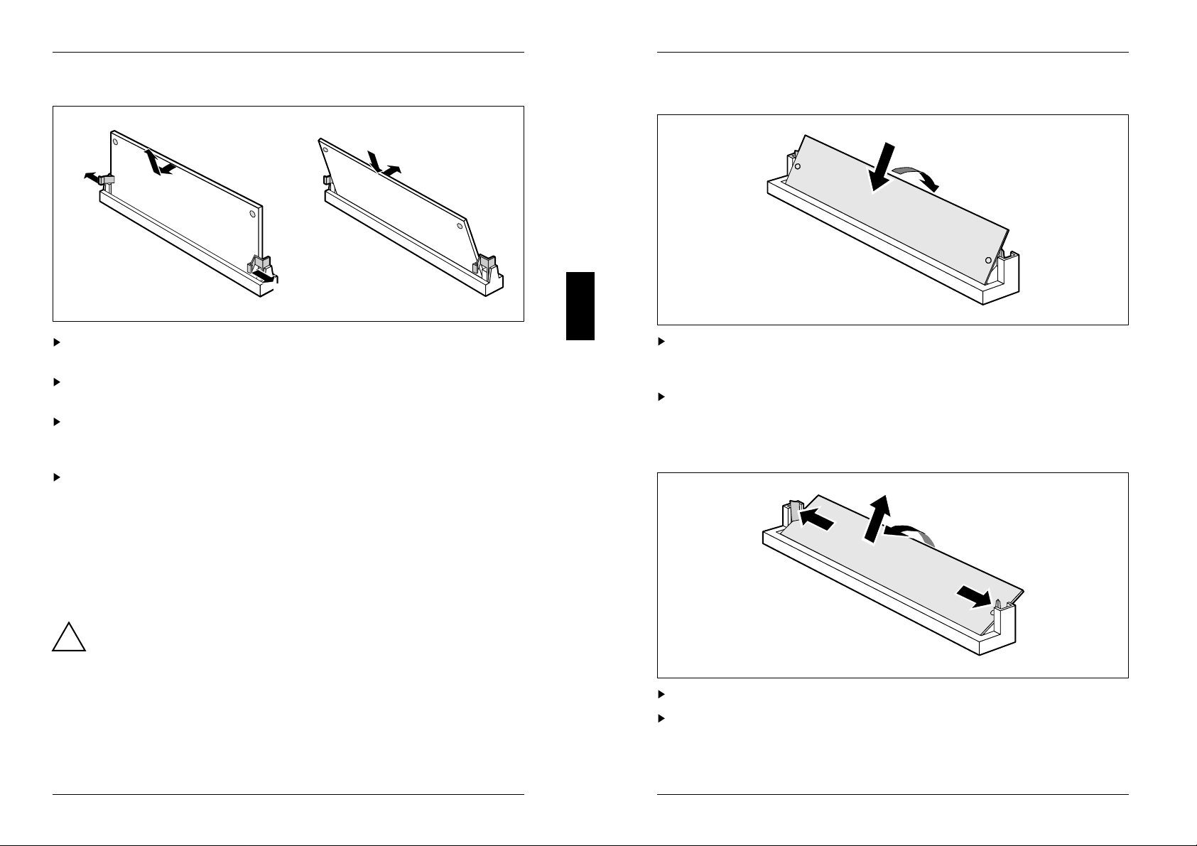
Replacing the voltage converter
4
1
Carefully push the retaining clips at each end of the voltage converter outwards
(1).
Tilt the voltage converter in the direction of the arrow (2) and pull it at an angle
out of the location (3).
Insert the voltage converter at an angle into the location (4).
Ensure that the key notch on the voltage converter is correctly aligned with the
retaining pins.
Tilt the voltage converter in the direction of the arrow (5) until it snaps into place.
3
2
1
5
Installing memory modules
2
1
Insert the memory module at angle into the appropriate location (1).
Ensure that the key notch and the two holes are correctly aligned with the
retaining pins.
Tilt the module down until it snaps into place (2).
Removing a memory module
Upgrading main memory
Four locations (bank 0 and bank 1) are available on the system board for installing
memory modules. The board supports a maximum of 128 Mbytes. You may use
memory modules of 4, 8, 16 or 32 Mbyte.
You may only use fast memory modules (access time = 70ns or less).
!
You must always add memory modules in pairs. In other words, you fit the
first pair to Bank 0 and Bank 1, and the second pair to Bank 2 and Bank 3.
Pairs of memory modules must have the same capacity and the same
access time.
A26361-D841-Z121-4-7619 35
1
Carefully push the retaining clips at each end of the module outwards (1).
Tilt the module upwards (2) and pull it at an angle out of the location (3).
36 A26361-D841-Z121-4-7619
3
2
1
Page 23
Add-on modules
Add-on modules
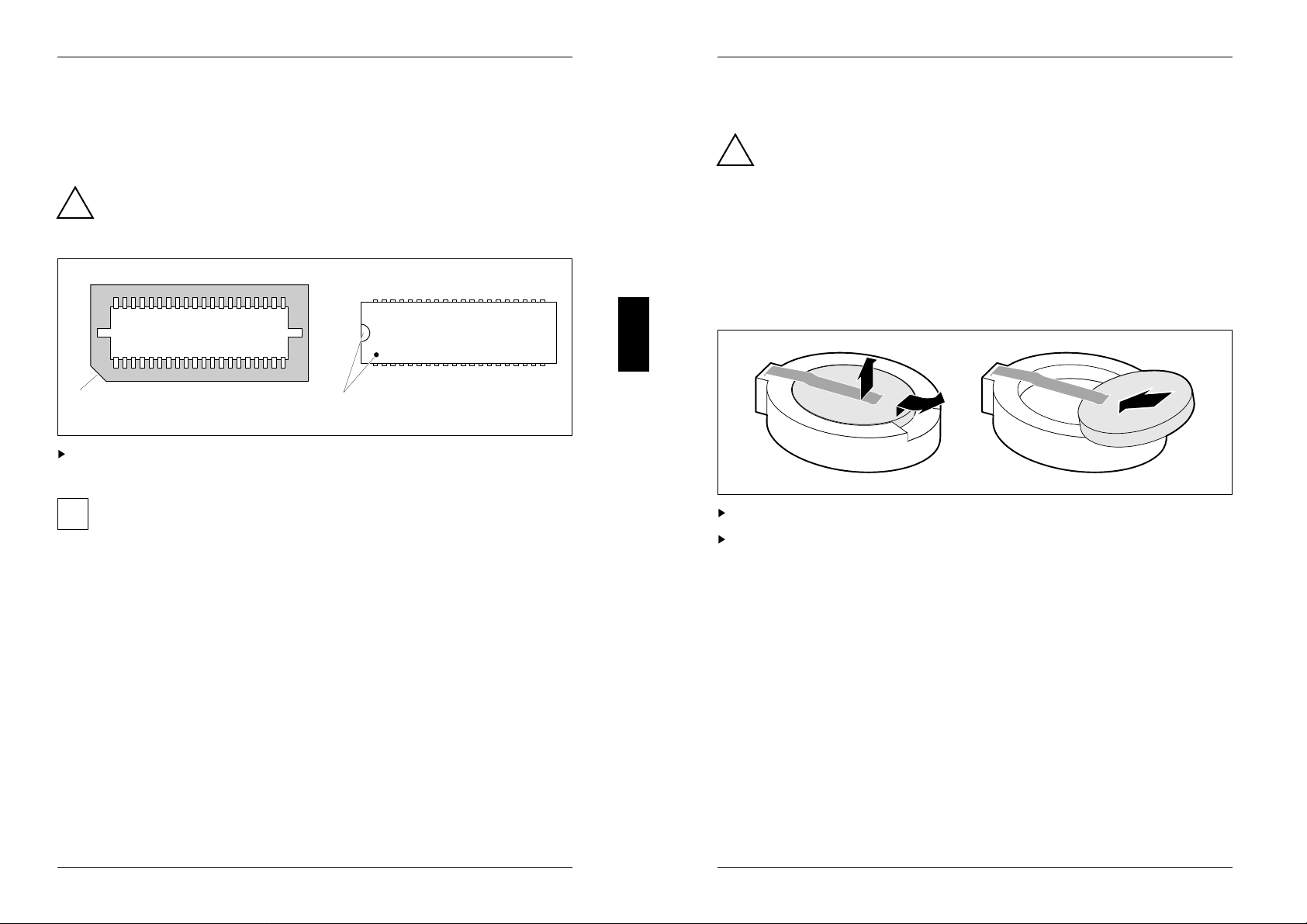
Upgrading the video memory
If your PC is supplied with a video memory configuration of 1 Mbyte, you may
enlarge the video memory up to 2 Mbytes.
Information on which DRAM components (DRAM 256K*16 16ns) you can
use is available from your sales office or the customer service.
!
Note the location of the DRAM chip when you plug in DRAM chip!
1
Insert the DRAM component in such a way that the mark on the upper side of
the DRAM component matches the position of the mark on the socket.
In order to be able to use the screen resolution, refresh rate and number of
i
colors available for a 2-Mbyte video memory, you must set the appropriate
screen display (e.g. using WDSETUP under MS-Windows or REFRATE under
Windows 95).
2
Replacing the lithium battery
Please note the information provided in the chapter "Important notes" in this
manual.
!
Incorrect replacement of the lithium battery may lead to a risk of explosion.
The lithium battery must be replaced with an identical battery or a battery
type recommended by the manufacturer (CR2032).
Do not throw lithium batteries into the trashcan. Your vendor or dealer or
their authorized representatives will take used batteries back free of charge
so that they can be recycled or disposed of in the proper manner.
Make sure that you insert the battery the right way round. The plus pole
must be on the top.
1
+
+
Lift the contact (1) a few millimeters and remove the battery from its socket (2).
Insert a new lithium battery of the same type in the socket (3).
2
+
3
+
A26361-D841-Z121-4-7619 37
38 A26361-D841-Z121-4-7619
Page 24
Interface pinouts and interrupts
Interface pinouts and interrupts
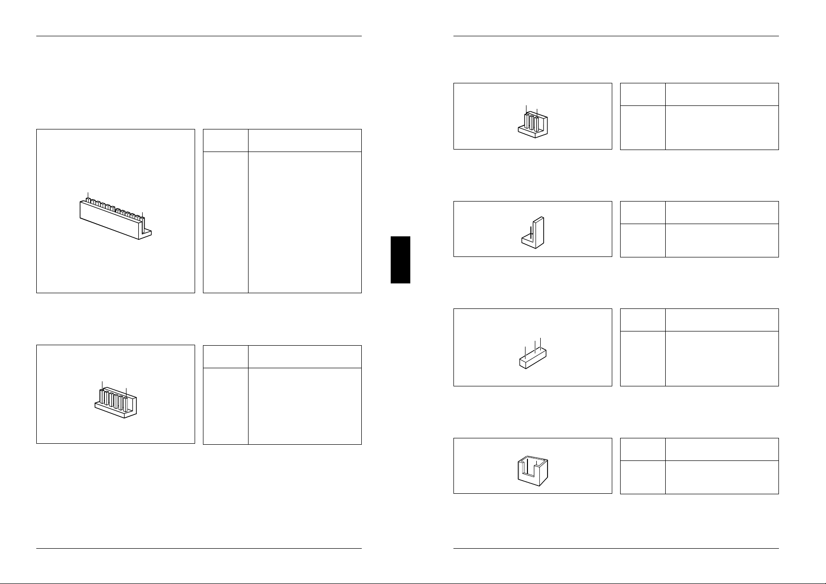
Connector for 5 V power supply
Pin Meaning
1 Power good
2 +5 V
1
12
Connector for 3.3 V power supply
1
6
3 +12 V
4 -12 V
5 0 V
6 0 V
7 0 V
8 0 V
9 -5 V
10 + 5 V
11 + 5 V
12 + 5 V
Pin Meaning
1 0 V
2 0 V
3 0 V
4 + 3.3 V
5 + 3.3 V
6 + 3.3 V
Connector for soft-off power supply
1
3
Pin Meaning
1 +5 V (auxiliary voltage)
2 Power Supply ON
3 0 V
Connector for soft-off power switch
1
2
Pin Meaning
1 +5 V (auxiliary voltage)
2 Power switch input
Connector for external loudspeaker
Pin Meaning
4
1
1 loudspeaker
2 coded
3 0 V
4 +5 V
Connector for remote power-on
2
1
Pin Meaning
A26361-D841-Z121-4-7619 39
1 0 V
2 Remote power-on
40 A26361-D841-Z121-4-7619
Page 25
Interface pinouts and interrupts
Interface pinouts and interrupts
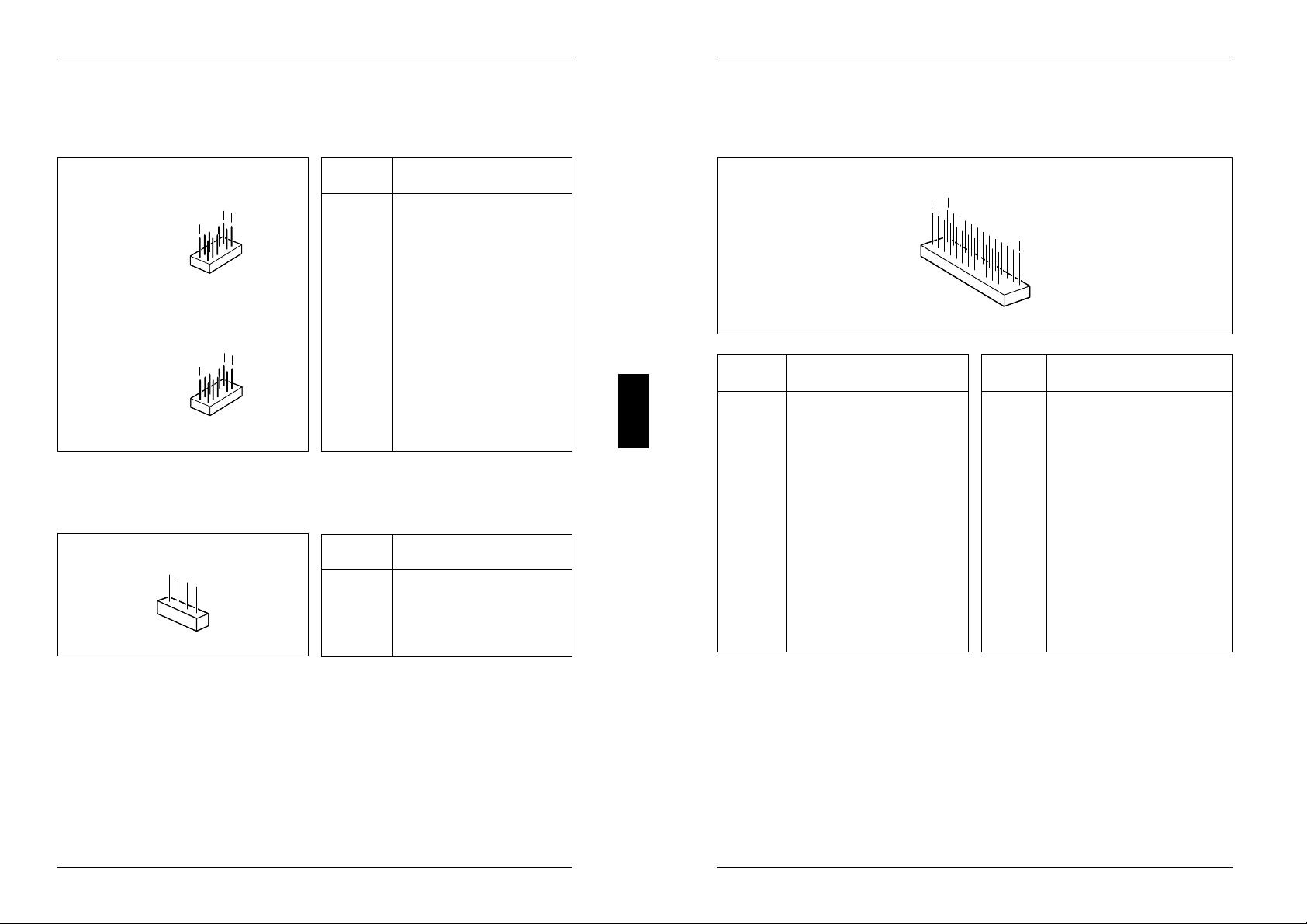
Connector for LED indicators
The entries in parentheses apply for the system board D842.
Pin Signal name
D841
D842
6
11
1
7
1
2
1 System unit ON
2 (3) not used
(enable power supply)
3 (5) coded
4 (7) not used
(auxiliary voltage)
5 (9) Reset switch
6 (11) +5 V
7 (2) 0 V
8 (4) 0 V (not used)
9 (6) coded
10 (8) 0 V (not used)
11 (10) 0 V
12 Hard disk drive LED
Connector for SCSI HD LED indicators
Pin Meaning
1
4
1 not used
2 SCSI Hard Disk LED
3 SCSI Hard Disk LED
4 not used
Connector for external monitor controller
(VESA VGA pass-through)
2
1
26
Pin Meaning Pin Meaning
1 0 V 14 Data 6
2 Data 0 15 0 V
3 0 V 16 Data 7
4 Data 1 17 0 V
5 0 V 18 Clock
6 Data 2 19 0 V
7 not used 20 Blanking
8 Data 3 21 0 V
9 not used 22 Horizontal Sync.
10 Data 4 23 not used
11 not used 24 Vertical Sync.
12 Data 5 25 keyed
13 not used 26 0 V
A26361-D841-Z121-4-7619 41
42 A26361-D841-Z121-4-7619
Page 26
Interface pinouts and interrupts
Interface pinouts and interrupts
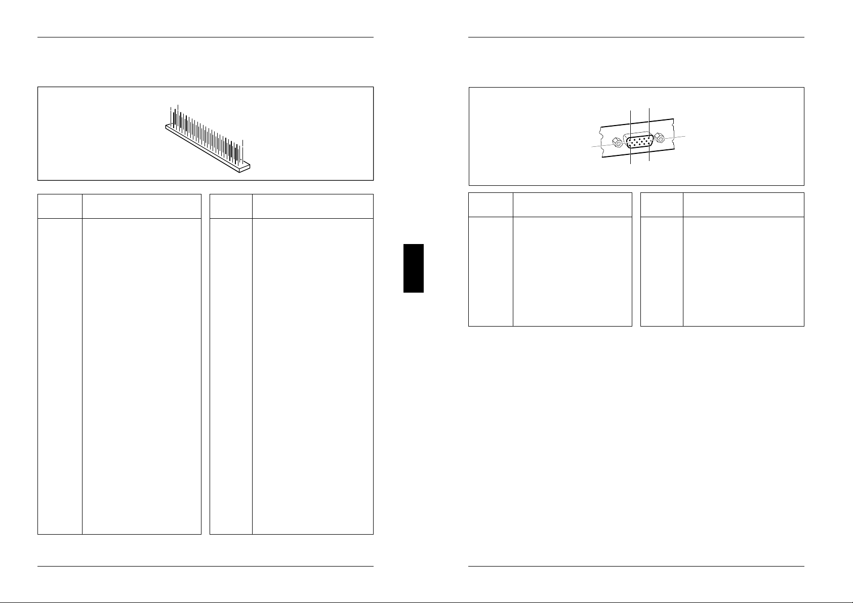
Connector for Imageport
49
50
1
Pin Meaning Pin Meaning
1 +5 V 26 free
2 +5 V 27 Host Data 0
3 0 V 28 0 V
4 0 V 29 Host Data 1
5 +12 V 30 Ext. Command
6 0 V 31 Image Write Strobe
7 Write Request 32 0 V
8 0 V 33 Reset
9 Image Data Mask0 34 0 V
10 free 35 Host Data 2
11 Image Data 0 36 Host Data 3
12 0 V 37 Host Data 4
13 Image Data 1 38 Host Data 5
14 Image Frame Sync 39 Host Data 6
15 Image Data 2 40 Host Data 7
16 Image Line Sync 41 free
17 Image Data 3 42 free
18 0 V 43 free
19 Image Data 4 44 free
20 Image Data Ready 45 free
21 Image Data 5 46 free
22 0 V 47 free
23 Image Data 6 48 free
24 Odd Image Data 49 0 V
25 Image Data 7 50 0 V
Connector for monitor
1
5
6
10
11
15
Pin Meaning Pin Meaning
1 Red 9 keyed (no pin)
2 Green 10 Sync. ground
3 Blue 11 Monitor ID bit 0
4 Display ID bit 2 12 Monitor ID bit 1
5 Ground 13 Horizontal
6 Red ground synchronization
7 Green ground 14 Vertical synchronization
8 Blue ground 15 Monitor ID bit 3
A26361-D841-Z121-4-7619 43
44 A26361-D841-Z121-4-7619
Page 27

Interface pinouts and interrupts
Interface pinouts and interrupts
Parallel interface
13
25
The parallel interface supports three transfer modes: SPP, EPP and ECP. SPP
mode (standard parallel port) is the mode traditionally used to drive a printer. The
EPP (Enhanced Parallel Port) and ECP (Extended Capabilities Port) modes are
transfer modes that allow transfer rates of 2 and 2.4Mbytes/s. These modes will
only work in connection with peripheral devices which specifically support them.
The new transfer modes are used among other things for connecting to SCSI or
IDE peripherals. The pinouts are different in all three modes.
Pinout in SPP mode
Pin Signal name Description
1 STROBE Data message
2-9 Data Lines 0-7 Data lines 0-7
10 ACKNOWLEDGE Data acknowledgement
11 BUSY Not ready to receive
12 PE End of paper
13 SELECT Device selection
14 AUTO Automatic new line
15 ERROR Device error
16 INIT Reset/initialize
17 SELECT IN Printer selection
18-25 GROUND Ground
1
14
Pinout in EPP mode
Pin Signal Signal direction
1 Write Output
2-9 Data Lines 0-7 Input/output
10 Intr Input
11 Wait Input
12 not used -- 13 not used Input
14 DStrb Output
15 not used -- 16 not used -- 17 AStrb Output
18-25 Ground
Pinout in ECP mode
Pin Signal Signal direction
1 HostClk Output
2-9 Data Lines 0-7 Input/output
10 PeriphClk Input
11 PeriphAck Input
12 AckReverse Input
13 Xflag Input
14 HostAck Output
15 PeriphRequest Input
16 ReverseRequest Output
17 ECP-Mode Output
18-25 Ground
A26361-D841-Z121-4-7619 45
46 A26361-D841-Z121-4-7619
Page 28
Interface pinouts and interrupts
Interface pinouts and interrupts
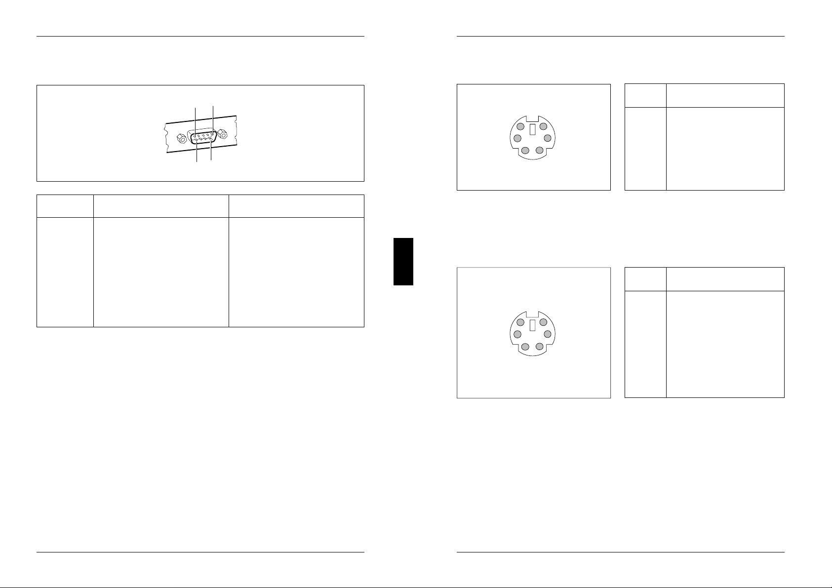
Serial interface
5
1
9
6
Pin Signal Meaning
1 DCD Data Carrier Detect
2 RxD Receive Data
3 TxD Transmit Data
4 DTR Data Terminal Ready
5 Signal Ground Ground
6 DSR Data Set Ready
7 RTS Request to Send
8 CTS Clear to Send
9 Ri Ring Indicator
PS/2 mouse port
Pin Signal
6
4
2
5
3
1
1 Mouse data
2 not used
3 0 V
4 +5 V
5 Mouse clock
6 not used
PS/2 keyboard port
The entries in parentheses are effective if the jumper X507 is inserted on 2-4 and
3-5 on the system board D842.
Pin Signal
1 Keyboard data
6
4
2
5
3
1
2 not used (Mouse data)
3 0 V
4 +5 V
5 Keyboard clock
6 not used or
power on switch
(Mouse clock)
A26361-D841-Z121-4-7619 47
48 A26361-D841-Z121-4-7619
Page 29

Interface pinouts and interrupts
Interrupt Request Levels and DMA channels
Interrupt Request Levels and DMA channels are listed below.
Interrupt Request Levels
IRQ0 = timer 0
IRQ1 = keyboard
IRQ2 = IRQ9
IRQ3 = serial interface 2 (COM2/COM4)
IRQ4 = serial interface 1 (COM1/COM3)
IRQ5 = free or parallel interface (LPT2)
IRQ6 = floppy disk controller
IRQ7 = parallel interface (LPT1/LPT3)
IRQ8 = real-time clock interrupt
IRQ9 = free, or VGA controller
IRQ10 = free
IRQ11 = free
IRQ12 = mouse
IRQ13 = math coprocessor
IRQ14 = IDE disk controller (first connector)
IRQ15 = IDE disk controller (second connector)
DMA channels
DMA0 = free
DMA1 = free
DMA2 = floppy disk controller
DMA3 = free/ECP mode
DMA4 = DMA channel cascading
DMA5 = free
DMA6 = free
DMA7 = free
A26361-D841-Z121-4-7619 49
Page 30

Error messages
Error messages
This chapter contains error messages generated by the system board.
Access Denied - System Halted
You have entered an illegal password three times. Restart the PC.
Vous avez entré trois fois un mot de passe erroné. Faites redémarrer le PC.
Ha introducido tres veces una contraseña incorrecta. Arranque nuevamente
el PC.
Avete indicato una parola chiave errata per tre volte. Avviate nuovamente il
PC.
Lösenordet har skrivits felaktigt tre gånger. Starta on datorn.
U hebt driemaal een ongeldig wachtwoord ingevoerd. Herstart de PC.
Access Denied - Press Any Key to Continue
You have entered an illegal password three times. Press any key. The PC
reboots.
Vous avez entré trois fois un mot de passe erroné. Actionnez une touche
quelconque. Le PC redémarre.
Ha introducido tres veces una contraseña incorrecta. Pulse una tecla. El PC
arranca nuevamente.
Avete indicato la parola chiave errata per tre volte. Digitate un tasto
qualsiasi. Il PC si riavvia.
Lösenordet har skrivits felaktigt tre gånger. Tryck valfri tangent. Datorn
omstartas.
U hebt driemaal een ongeldig wachtwoord ingevoerd. Druk op een
willekeurige toets. Hierna herstart de PC
Diskette drive failure
Diskette drive 0 failure
Diskette drive 1 failure
Check the entry defining the drive type in the Diskette field in the setup menu.
Check the floppy disk drive's connecting cables.
Contrôlez le type du lecteur de disquette dans la zone DISKETTE du menu
setup ainsi que ses raccordements physiques.
Verifique en el menú setup el tipo de unidad en el campo DISKETTE y las
conexiones de la unidad de disquetes.
Verificate nel menu di setup nel campo Diskette il tipo del drive ed i
collegamenti del floppy disk drive.
Kontrollera i Setup-menyns inmatningsfält Diskett diskettstationstypen och
anslutningarna till diskettstationen.
Kontroleer de diskette-eenheid die is opgegeven in het veld Diskette van het
Setup-menu en tevens de aansluitingen voor de diskette-eenheid.
Fixed disk configuration error
Fixed disk controller failure
Fixed disk 0 failure
Fixed disk 1 failure
Check the entries defining the hard disk type in the Hard Disk Ctrlr,
Hard Disk 1, Hard Disk 2, Hard Disk 3, Hard Disk 4 in the setup menu. Check
the drive's connecting cables and jumper and switch settings.
Contrôlez le type du disque dur dans les zones Hard Disk 1, Hard Disk 2,
Hard Disk 3 et Hard Disk 4 du menu setup ainsi que ses raccordements
physiques et ses cavaliers.
Verifique en el menú setup los registros en los campos HARD DISK 1,
HARD DISK 2, Hard Disk 3 y Hard Disk 4 para el tipo de disco duro, así como
las conexiones y los puentes enchufables en la unidad de disco duro.
Verificate nel menu di setup nel campo Hard Disk Ctrlr, Hard Disk 1,
Hard Disk 2, Hard Disk 3 e Hard Disk 4 gli inserimenti relativi al tipo di disco
rigido ed i collegamenti ed i ponticelli del disco rigido.
A26361-D841-Z121-4-7619 51
Kontrollera i Setup-menyn allt som skrivits in i inmatningsfälten Hard Disk
Ctrlr, Hard Disk 1, Hard Disk 2, Hard Disk 3, Hard Disk 4 för den hårddisktypen
samt anslutningarna och insticksbryggorna på hårddiskstationen.
Kontroleer het type harde-schijfeenheid dat is opgegeven in de velden
(Hard Disk Ctrlr, Hard Disk 1, 2, 3, 4) van het Setup-menu en tevens de
verbindingen en de brugstekkers op de harde-schijfeenheid.
52 A26361-D841-Z121-4-7619
Page 31

Error messages
Error messages
Incorrect Password
You have entered an illegal password. Enter the password again and press
the Enter key.
Vous avez fait une erreur dans le mot de passe. Entrez à nouveau le mot de
passe et actionnez la touche d'entrée.
Ha introducido una contraseña incorrecta. Introduzca nuevamente la
contraseña y pulse la tecla de entrada
Avete indicato una parola chiave errata. Indicate nuovamente la parola
chiave e digitate il tasto Invio.
Du har angivit ett felaktigt lösenord. Skriv in det en gång till och tryck Enter.
U hebt een ongeldig wachtwoord ingevoerd. Voer opnieuw het wachtwoord
in en druk op de Enter-toets.
Invalid configuration information
Check all the entries in the setup menu. If this error occurs each time you
power up the PC, contact your sales office or customer service.
Vérifiez tous les paramètres du menu setup. Si ce message apparaît chaque
fois que vous remettez votre PC sous tension, adressez-vous au S.A.V.
Verifique todos los registros en el menú setup del sistema. Si cada vez que
usted conecta su sistema se produce este error, diríjase al Servicio Técnico.
Verificate tutti i valori nel menu di setup. Se questo messaggio si manifesta
dopo ogni accensione, rivolgeteVi al Vostro servizio di assistenza tecnica.
Kontrollera i Setup-menyn allt som skrivits in. Visas detta felmeddelande
varje gång Du knäpper på, kontakta kundservice.
Kontroleer alle opdrachten in het Setup-menu. Als deze fout zich voordoet
telkens u de PC aanschakelt, neemt u best kontakt op met uw
onderhoudsdienst.
I/O Expansion board NMI
I/O Expansion board NMI, Slot x
Restart your PC. If the error persists, contact your sales office or customer
service
Faites redémarrer votre PC. Si ce message apparaît à plusieurs reprises,
contactez le S.A.V.
Arranque nuevamente el PC. En caso que este error se produzca
repetidamente, informe al Servicio Técnico.
Avviate nuovamente il PC. Se l'errore si ripete, informate il Vostro servizio di
assistenza tecnica.
Starta om datorn. Visas detta felmeddelande upprepade gånger, v g kontakta
kundservice.
Herstart uw PC. Als de fout zich weer zou voordoen, neemt u best kontakt op
met uw onderhoudsdienst.
!!! HARD DISK WARNING !!!
Boot sector has been modified.
Confirm the new boot sector in SETUP,
and run a virus scan program.
The boot sector of your bootable hard disk drive has been modified since the
last boot-up (e.g., a new operating system has been installed of the system
has been infected by a virus). If the change to the boot sector was intentional
(e.g., you have installed a new operating system), then acknowledge the
Virus Warning function in the System Security Options page of the setup menu
by selecting CONFIRM.
If you are not sure what modified the boot sector, you should check your
computer for virus infection with the aid of an appropriate virus scanner
program.
Le secteur d'initialisation du lecteur prêt à démarrer a été modifié depuis le
dernier démarrage du système (nouveau système d'exploitation ou infection
par virus, par exemple). Si vous souhaitez modifier le secteur d'initialisation
ou si la modification est connue, validez avec CONFIRM la fonction Virus
Warning du menu setup System Security Options.
A26361-D841-Z121-4-7619 53
Si l'origine des modifications du secteur d'initialisation est inconnue, il
convient de lancer un programme spécifique de détection des virus
informatiques.
54 A26361-D841-Z121-4-7619
Page 32

Error messages
Error messages
El sector de inicialización de la unidad de disquetes arrancable ha sido
modificado desde el último arranque de sistema (p. ej. debido a la instalación
de un nuevo sistema operativo o la "infección" por un virus). Si conoce y
aprueba la modificación del sector de arranque, p. ej. tras la instalación de
un nuevo sistema operativo, confirme con CONFIRM la función Virus Warning
de la opción Security Options en el menú de setup (configuración).
Si desconoce la causa de las modificaciones en el sector de inicialización,
proceda a ejecutar un programa adecuado para combatir el virus informático.
Il settore di lancio (boot) del drive pronto per l'avvio è cambiato dall'ultimo
avvio di sistema (p.es. nuovo sistema operativo oppure presenza di virus).
Se il cambiamento del settore di lancio è voluto oppure conosciuto, come nel
caso di installazione di un nuovo sistema operativo, confermate nel menu di
setup System Security Options la funzione Virus Warning con CONFIRM.
Se la causa del cambiamento del settore di lancio e sconosciuta, è
necessario avviare un programma per la ricerca di virus.
Den startbara diskettstationens bootsektor har förändrats sedan den senaste
systemstarten (t ex nytt operativsystem eller en virus). Bekräfta funktionen
Virus Warning i Setup-menyn System Security Options med CONFIRM om
bootsektorns förändring är önskad eller känd, som t ex efter installation av ett
nytt operativsystem.
Om orsaken till bootsektorns förändring är okänd, måste ett lämpligt program
för datorvirussökning startas.
De bootsector van het opstartbare magneetbandloopwerk is sedert de laatste
opstarting van het systeem veranderd (bv. nieuw besturingssysteem of
virusaanval). Is de verandering van de bootsector gewenst of bekend, b.v. na
de installatie van een nieuw besturingssysteem, dan bevestigt u in het setupmenu System Security Options de functie Virus Warning (waarschuwing
tegen virussen) met CONFIRM (bevestigen).
Keyboard is locked - unlock
Unlock the PC and restart the system.
Débloquez le PC et faites redémarrer le système.
Desbloquee el teclado y arranque nuevamente el PC.
Sbloccate il PC e riavviate il sistema operativo.
Aktivera PCn och starta systemet på nytt.
Deblokkeer de PC en start het systeem opnieuw op.
Keyboard failure
Keyboard stuck key failure
Check whether a key is sticking and whether the keyboard is connected
correctly.
Vérifiez que les touches fonctionnent bien et que le clavier est raccordé
correctement.
Verifique si alguna tecla quedó enclavada y si el teclado está conectado
correctamente.
Verificate se un tasto rimane incastrato.
Verificate se la tastiera è collegata in modo corretto.
Kontrollera om det är någon tangent som förblir orörlig.
Kontrollera att tangentbordet är anslutet helt korrekt.
Kontroleer of er een toets geklemd zit en of het toetsenbord op de juiste
wijze is aangesloten.
Is de oorzaak van de veranderingen van de bootsector onbekend, dan moet
een speciaal daarvoor bestemd programma opgestart worden om de
computervirus te ontdekken.
A26361-D841-Z121-4-7619 55
56 A26361-D841-Z121-4-7619
Page 33

Error messages
Error messages
Memory parity error at ...
Unresolved memory parity error
Restart your PC. If the system reports this error each time you switch it on,
contact your sales office or customer service.
Faites redémarrer votre PC. Si ce message apparaît chaque fois que vous
remettez votre PC sous tension, adressez-vous au S.A.V.
Arranque nuevamente el PC. Si cada vez que usted conecta su sistema se
produce este error, diríjase al Servicio Técnico.
Avviate nuovamente il PC. Se l'errore si ripete, informate il Vostro servizio di
assistenza tecnica.
Starta om datorn. Visas detta felmeddelande varje gång Du knäpper på,
kontakta kundservice.
Herstart uw PC. Als de fout zich weer zou voordoen, neemt u best kontakt op
met uw onderhoudsdienst.
Memory failure at xxxx read xxxxx expecting xxxxx
Restart your PC. If the system reports this error each time you switch it on,
contact your sales office or customer service.
Faites redémarrer votre PC. Si ce message apparaît chaque fois que vous
remettez votre PC sous tension, adressez-vous au S.A.V.
Arranque nuevamente el PC. Si cada vez que usted conecta su sistema se
produce este error, diríjase al Servicio Técnico.
Avviate nuovamente il PC. Se l'errore si ripete, informate il Vostro servizio di
assistenza tecnica.
Not a boot diskette No boot device available No boot sector on hard disk Diskette read failure Hard disk read failure -
Insert the operating system floppy disk in the floppy disk drive and press
Enter.
Check the entries for the floppy disk and hard disk types in the setup menu.
Insérez la disquette contenant le système d'exploitation dans le lecteur de
disquette et appuyez sur la touche d'entrée.
Contrôlez les paramètres concernant les types de disquette et de disque dur
dans le menu setup.
Coloque el disquete de sistema operativo en la unidad y pulse la tecla de
entrada. Verifique los registros para el tipo de disquetes y para el disco duro
en el menú setup.
Inserite il dischetto di sistema operativo nel floppy disk drive e premete il
tasto Invio.
Verificate nel menu di setup gli inserimenti relativi al tipo del floppy disk drive
e del disco rigido.
Sätt in systemdisketten i diskettstationen och tryck Enter.
Kontrollera i Setup-menyn allt som skrivits in för den diskett- och
hårddisktypen.
Steek de diskette met het besturingssysteem in de diskette-eenheid en druk
op de Enter-toets. Kontroleer in het Setup-menu de opdrachten voor het type
diskette-eenheid en harde-schijfeenheid.
Starta om datorn. Visas detta felmeddelande varje gång Du knäpper på,
kontakta kundservice.
Herstart uw PC. Als de fout zich weer zou voordoen, neemt u best kontakt op
met uw onderhoudsdienst.
A26361-D841-Z121-4-7619 57
58 A26361-D841-Z121-4-7619
Page 34

Error messages
Error messages
No timer tick interrupt
Timer 2 failure
Shutdown failure
Gate A20 failure
Unexpected interrupt in protected mode
Restart your PC. If the system reports this error each time you switch it on,
contact your sales office or customer service.
Faites redémarrer votre PC. Si ce message apparaît chaque fois que vous
remettez votre PC sous tension, adressez-vous au S.A.V.
Arranque nuevamente el PC. Si cada vez que usted conecta su sistema se
produce este error, diríjase al Servicio Técnico.
Avviate nuovamente il PC. Se l'errore si ripete, informate il Vostro servizio di
assistenza tecnica.
Starta om datorn. Visas detta felmeddelande varje gång Du knäpper på,
kontakta kundservice.
Herstart uw PC. Als de fout zich weer zou voordoen, neemt u best kontakt op
met uw onderhoudsdienst.
Passwords entered do not match
The password you entered in confirmation was different from the first
password. Enter the password again and press the Enter key.
La confirmation du mot de passe est incorrecte. Entrez à nouveau le mot de
passe et actionnez la touche d'entrée.
Ha confirmado incorrectamente la contraseña. Introduzca nuevamente la
contraseña y pulse la tecla de entrada.
Avete confermato la parola chiave in modo errato. Indicate nuovamente la
parola chiave e digitate il tasto Invio.
Du har bekräftat lösenordet fel. Skriv in lösenordet en gång till och tryck
Enter.
Pointing device failure
Check whether the mouse is properly connected.
Vérifiez si la souris est correctement connectée.
Verifique si el ratón está conectado correctamente.
Controllate che il mouse sia collegato correttamente.
Kontrollera att musen är anslutet helt korrekt.
Controleer of de muis correct aangesloten is.
Real time clock failure
Time-of-day not set - run SETUP program
Access the setup menu and enter the correct time in the Time field. If the
system reports this error each time you switch it on, contact your sales office
or customer service.
Appelez le menu setup et inscrivez l'heure exacte dans la zone TIME. Si ce
message apparaît chaque fois que vous remettez votre PC sous tension,
adressez-vous au S.A.V.
Llame el menú setup y registre el valor correcto para la hora en el campo
Time. Si cada vez que usted conecta su sistema se produce este error,
diríjase al Servicio Técnico.
Richiamate il menu di setup e indicate l'ora esatta nel campo Time. Se
l'errore si ripete, informate il Vostro servizio di assistenza tecnica.
Anropa Setup-menyn och skriv in rätt klockslag i inmatningsfältet Time.
Visas detta felmeddelande varje gång Du knäpper på, kontakta kundservice.
Roep het Setup-menu op en voer de juiste tijdnotatie in het veld Time in. Als
deze fout zich voordoet telkens u de PC aanschakelt, neemt u best kontakt
op met uw onderhoudsdienst.
U hebt een ongeldig wachtwoord ingevoerd. Voer opnieuw het wachtwoord
in en druk op de Enter-toets.
A26361-D841-Z121-4-7619 59
60 A26361-D841-Z121-4-7619
Page 35

Error messages
Security Features Not Changed - Press Any Key to Continue
You have failed three times in succession to correctly confirm the password.
The password has not been set. Press any key. The PC will reboot.
Vous avez confirmé le mot de passe trois fois de manière incorrrecte.
Actionnez une touche quelconque.
Ha confirmado tres veces incorrectamente la contraseña. Si pulsa una tecla,
el PC ejerce sus operaciones normales. No se ha asignado ninguna
contraseña.
Avete confermato per tre volte la parola chiave in modo errato e per questo
non è stata assegnata. Premete un tasto qualsiasi.
Du har bekräftat lösenordet fel tre gånger som därför inte träder i kraft. Tryck
valfri tangent. Starta on datorn.
Het paswoord werd drie keer verkeerd ingegeven en werd daarom niet
vrijgegeven. Druk op een toets. De PC start opnieuw.
A26361-D841-Z121-4-7619 61
Page 36
Index
Index
1
!
1
i
1
1dx
1.2M, Diskette 10
1.4M, Diskette 10
128K, system BIOS 19
2.8M, Diskette 10
360K, Diskette 10
3 1/2-inch floppy disk drive 10
528 Mbyte hard disks 25
5 1/4-inch floppy disk drive 10
64-bit microprocessor 2
720K, Diskette 10
8K BLOCK XFER
Hard Disk Transfer Mode 25
96K, system BIOS 19
A
Accelerator, Windows 2
Adaptec-SCSI controller, Notes 8
Adding main memory 35
Additional Hard Disk Options 24
Additional System Options 9, 19
AUTO
Hard Disk 12
PCI Interrupt Mapping 23
AUTO SELECT
Hard Disk LBA Translation 26
Hard Disk Transfer Mode 25
Available base memory 12
B
Base address
PCI adaptor I/O operations 23
PCI adaptor memory 22
Base Memory 12
Battery 7
BIDIRECTION 16
BIOS
recovery 31
update 31
ROM 21
Board
D841 3
D842 4
Boot-sector modifications 18
Booting the operating system 14
Bus interface 2
C
Cache 2, 20
operation 21
Cache Adaptor ROM 22
Cache BIOS ROM 21
Cache Mode 21
Capacity, hard disk 25
CHANGE PASSWORD
Security Features 14
Changing
lithium battery 38
password 14
Channels, DMA 49
Color palette 23
COLOR 40 12
COLOR 80 12
Color Palette Snoop 23
COM1 pinout 47
COM1 (3F8h) serial interface 1 15
COM2 pinout 47
COM2 (2F8h) serial interface 2 15
COM3 (3E8h) serial interface 1 15
COM4 (2E8h) serial interface 2 15
Computer viruses 18
Configuration
parallel interface 15, 16
serial interface 15
Configuration (Continued) DISABLED (Continued)
using setup menu 9 Security Features 14
CONFIRM Virus Warning 18 serial interface 15
Connectors 2, 3, 4 Setup Prompt 17
3.3 V power supply 39 Standby Timeout 27
5 V power supply 39 System Tic 29
external loudspeaker 33, 40 Video 27
external monitor controller 33 Virus Warning 18
for SCSI HD LED indicators 41 Disabling
IDE hard disk drive 33 floppy disk controller 17
Imageport 33, 43 hard disk controller 24
indicator 41 mouse controller 16
processor fan 33 Disk controller 2
remote power-on 40 DISKETTE LOCK System Load 14
soft-off power supply 40 DISKETTE SWAP System Load 14
VESA VGA pass-through 42 Diskette A 10
Controller 2 Diskette B 10
floppy disk drive 17 Diskette Ctrlr 17
hard disk 24 Diskette Write 17
Courier 1 Display adaptors 23
bold 1 DMA channels 49
CPU Speed Standby Function 28 Duration of self-test 18
DE
Date 10, 14, 19, 22, 24, 27 ECP 16
DISABLED ECP AND EPP 16
Cache 20 ECP mode, parallel interface 46
Cache BIOS ROM 21 EGA/VGA 12
Cache Mode 21 ENABLED
Color Palette Snoop 23 Color Palette Snoop 23
CPU Speed 28 Diskette Ctrlr 17
Diskette Ctrlr 17 Diskette Write 17
Diskette Write 17 Flash Write 16
Flash Write 16 Hard Disk 28
Hard Disk 28 Hard Disk Ctrlr 24
Hard Disk Ctrlr 24 IRQ 29
Hard Disk, LBA Translation 25 Mouse 29
IRQ 29 Mouse Ctrlr 16
Mouse 29 Parity Checking 23
Mouse Ctrlr 16 Quick Load 18
Parallel 15 Setup Prompt 17
Parity Checking 23 System Tic 29
Quick Load 18 Video 27
A26361-D841-Z121-4-7619 63
64 A26361-D841-Z121-4-7619
Page 37

Index
Index
ENABLED (Continued) Fonts, meanings 1
Virus Warning 18 Foutmeldingen 51
Enabling Function key F1 9
floppy disk controller 17
hard disk controller 24 G
mouse controller 16 Graphics processor
standby mode 27 TSENG ET4000/W32P 2
Enhanced Parallel Port mode,
parallel interface 46 H
Enlarging Video memory 37 Handle modules with ESDs 8
EPP 16 Hard disk
EPP mode, parallel interface 46 capacity 25
Error messages 51 controller 2, 24
Error Halt 13 standby function 28
ESD modules 8 motor, powering down 26
ESDI hard disk 11 type 11
ET4000/W32P, HARD DISK WARNING 18
TSENG graphics processor 2 Hard Disk 11
Explanation of Standby Function 28
fonts 1 Hard Disk 1 25, 26
symbols 1 Hard Disk 2 25, 26
Extended Capabilities Port mode, Hard Disk 3 25, 26
parallel interface 46 Hard Disk 4 25, 26
Extended Memory 12 Hard Disk Ctrlr 24
External Help text, invoking 9
cache (second level cache) 20, 32 HIGH Speed Select 12
loudspeaker connector 2, 40
monitor controller connector 2 I
video controller connector 42 I/O operations, PCI adaptor base
address 23
F I/O Base Address 23
F2 FOR SETUP prompt 17 IDE hard disk
Features system board 2 controller 24
Felmeddelanden 51 Power Down 26
First-level cache (internal cache) 20 transfer rate 25
Flash BIOS, write-protection 16 Imageport 2
Flash Write 16 connector pinout 43
Floppy disk controller 2 location 33
disabling 17 Important notes 7
enabling 17 Indicators connector 41
Floppy disk drive Installing memory modules 36
type 10 Interfaces 2, 3, 4
write protection 17, 31 parallel 45
Interfaces (Continued) Location (Continued)
pinouts 39 voltage converter 33
serial 47 Loudspeaker connector 2
INTERN AND EXTERN, cache 20 LOW CPU Speed 28
INTERN ONLY, cache 20 LOW Speed Select 12
Internal cache 2 LPT1 pinout 45
Interrupt LPT1 (378h) Parallel 15
Request Levels 49 LPT2 (278h) Parallel 15
standby mode, terminating 29 LPT3 (3BCh) Parallel 15
interrupts 49
IRQ standby modus, terminating 29 M
IRQ09 Wakeup Event 29 Main memory 35
IRQ10 Wakeup Event 29 location 33
IRQ11 Wakeup Event 29 Meanings of
IRQ3 15 fonts 1
IRQ4 15 symbols 1
IRQ7 15 Memory 2
configuration, external cache 32
J main 35
Jumper 30 PCI adaptor 22
setting 32 upgrade 35
Video memory 37
K Base Address 22
Keyboard Memory modules 35
password 14 installing 36
port 2, 48 removing 36
setting 32 Mensaje de error 51
Messagio di errore 51
L Modifications to the boot sector 18
Large hard disks 25 Modules with ESDs 8
LBA Translation 25, 26 Monitor
Lithium battery 7 connector pinout 44
changing 38 controller connector 2
location 33 interface 2
Loading the operating system 14 MONO 12
Location Mouse
connector controller
external monitor controller 33 disabling 16
jumper 30 enabling 16
lithium battery 33 interface 2
processor 33 port pinout 48
switch block 30 setting 32
video memory 33 terminating standby mode 29
A26361-D841-Z121-4-7619 65
66 A26361-D841-Z121-4-7619
Page 38

Index
Index
Mouse (Continued) PCI adaptor ROM 20
Wakeup Event 29 PCI Interrupt Mapping 23
Mouse Ctrlr 16 Pentium OverDrive processor 2
Multimedia adaptors 23 Performance 20, 21
Pinout
N 3.3 V power supply 39
NO 5 V power supply 39
Cache Adaptor ROM 22 external loudspeaker 40
Shadow Adaptor ROM 20 Imageport 43
NO DISK ERROR HALT 13 indicator 41
NO HALT ON ALL ERRORS 13 keyboard port 48
NO HALT ON ANY ERRORS 13 monitor connector 44
NO KEYBOARD ERROR HALT 13 mouse port 48
NO KEYBOARD OR DISK HALT 13 parallel interface 45
NONE remote power-on 40
Diskette 10 SCSI HD LED indicators 41
Hard Disk 12 serial interface 47
PCI Interrupt Mapping 23 soft-off power supply 40
NONSTANDARD System Load 14 VESA VGA pass-through 42
Notes on software 8 Pointing device setting 32
Ports 2, 3, 4
O Power down, IDE hard disk 26
Operating system, loading 14 Power Management Configuration,
setup menu 27
P Power supply
Pages in the setup menu 9 3.3 V connector 39
Parallel 15, 16 5 V connector 39
Parallel interface 2 Power switch connector,
Parallel interface soft-off power supply 40
configuring 15, 16 Power-save feature, IDE hard disk 26
ECP mode 46 Powering down the hard disk motor 26
EPP mode 46 PRINTER 16
pinout 45 Processor 2
SPP mode 45 cache (internal cache) 20
Parity Checking 23 location 33
Par Mode 16 upgrading 34
Password 14 Programs with time loops 8
PC speed 12 Prompt, F2 FOR SETUP 17
PCI 1 PS/2 mouse port 29
adaptor, base address 22
PCI Device Configuration, Q
setup menu 22 Quick self-test 18
interrupt 23 Quick Load 18
R Setup password 14
Recovering BIOS 31 Setup memory 2
REDUCED CPU Speed 28 Setup Prompt 17
Remote power-on 2 Shadow Adaptor ROM 20
connector 40 Shadow BIOS ROM 20
Removing memory module 36 Sockets 3, 4
Replacing voltage converter 35 Soft-off power supply, connector 40
ROM 21, 22 Source of wakeup event 28
ROM BIOS 20 Speed system speed 12
PCI adaptor 20 Speed Select 12
SPP modes, parallel interface 45
S STANDARD
SCO-UNIX, Notes 8 Hard Disk Transfer Mode 25
Screen System Load 14
memory 2 Standard Parallel Port mode 45
pages 9 Standby function
resolution 4 CPU speed 28
SCSI hard disk controller 28
hard disk 11 video 27
HD LED indicators, pinout 41 Standby mode
Second level cache 2, 20 enabling 27
Security features 13, 14 termination 29
Self-test duration 18 Standby Timeout 27
Serial interface 2 STOPPED CPU Speed 28
configuring 15 Switch block 3, 4, 30
pinout 47 Symbols, meanings 1
Serial 1 15 System
Serial 2 15 Information 9
Settings 9 password 14
BIOS update 31 Security Options, Setup Menu 13
jumper 30, 32 speed 12
keyboard 32 start-up, quick 18
mouse 32 Tic standby mode, terminating 29
switches 30 SYSTEM AND SETUP LOCK Security
Setup LOCK Security Features 14 Features 14
Setup menu 9 SYSTEM AND VIDEO BIOS
Additional Hard Disk Options 24 Cache BIOS ROM 21
Additional System Options 19 Shadow BIOS ROM 20
pages 9 System BIOS 19
Power Management location 19
Configuration 27 memory area 19
System Configuration 10, 22 size 19
System Security Options 13
A26361-D841-Z121-4-7619 67
68 A26361-D841-Z121-4-7619
Page 39

Index
SYSTEM BIOS ONLY Voltage converter
Cache BIOS ROM 21 location 33
Shadow BIOS ROM 20 replacing 35
System board
D841 3 W
D842 4 Wakeup event source 28
System Configuration 9, 10, 13, 19, Wakeup Timer 27
22, 24, 27, 30 Windows accelerator 2
System Load 14 WRITE BACK Cache Mode 21
System Tic Wakeup Event 29 Write protection
flash BIOS 16
T floppy disk drive 17, 31
Technical specifications 2 WRITE THROUGH Cache Mode 21
Time 10, 14, 19, 22, 24, 27
Time loops 8, 12 Y
Transfer Mode 25 YES
Transfer rate, IDE hard disk 25 Cache Adaptor ROM 22
TSENG ET4000/W32P, Shadow Adaptor ROM 20
graphics processor 2
U
Update BIOS 31
Upgrading
main memory 35
processor 34
video memory 37
V
V.24 interface pinout 47
VESA VGA pass-through connector
42
Video
adaptors 23
memory 2, 33, 37
Standby Function 27
VIDEO BIOS 20
VIDEO BIOS ONLY
Cache BIOS ROM 21
Video Display 12
Virus infection 18
Virus Warning 18
A26361-D841-Z121-4-7619 69
 Loading...