

Page 1

Preface, Contents
Advanced PC Configuration -
Introduction
Getting Started
1
SIMATIC NET
Commissioning PC Stations
- Manual and Quick Start
Manual
Configured Mode
PG Operation
Additional Functions
Configuring the OPC Server
Using the CP 1616 as a
PROFINET IO Controller/Device
Examples
Industrial Ethernet
PROFIBUS-DP
Unspecified S7 Connection
SNMP
PROFINET
Tools
2
3
4
5
6
7
8
9
10
11
Release 5/2005
C79000-G8976-C156-07
Station Configuration Editor
NCM PC
PC Station Wizard
Symbol File Configurator
Configuration Console
OPC Scout
DCOM Settings
Appendix
12
13
14
15
16
17
18
Page 2

Classification of the Safety-Related Notices
follows according to the level of danger:
This manual contains notices which you should observe to ensure your own
personal safety, as well as to protect the product and connected equipment. These
notices are highlighted in the manual by a warning triangle and are marked as
Danger
!
!
!
indicates that death or severe personal injury will result if proper precautions are
not taken.
Warning
indicates that death or severe personal injury can result if proper precautions are
not taken.
Caution
with warning triangle indicates that minor personal injury can result if proper
precautions are not taken.
Caution
without warning triangle indicates that damage to property can result if proper
precautions are not taken.
Notice
indicates that an undesirable result or status can occur if the relevant notice is
ignored.
Note
highlights important information on the product, using the product, or part of the
documentation that is of particular importance and that will be of benefit to the
user.
2
Commissioning PC Stations - Manual and Quick Start
C79000-G8976-C156-07
Release 5/2005
Page 3

Trademarks
SIMATICR, SIMATIC HMIR and SIMATIC NETR are registered trademarks of
SIEMENS AG.
Third parties using for their own purposes any other names in this document which
refer to trademarks might infringe upon the rights of the trademark owners.
Safety Instructions Regarding your Product:
Before you use the product described here, read the safety instructions below
thoroughly.
Qualified Personnel
Only qualified personnel should be allowed to install and work on this equipment.
Qualified persons are defined as persons who are authorized to commission, to
ground, and to tag circuits, equipment, and systems in accordance with established safety practices and standards.
Correct Usage of Hardware Products
Note the following
Warning
!
This device and its components may only be used for the applications described in
the catalog or the technical description, and only in connection with devices or
components from other manufacturers which have been approved or
recommended by Siemens.
This product can only function correctly and safely if it is transported, stored, set
up, and installed correctly, and operated and maintained as recommended.
Before you use the supplied sample programs or programs you have written
yourself, make certain that no injury to persons nor damage to equipment can
result in your plant or process.
EU Directive: Do not start up until you have established that the machine on which
you intend to run this component complies with the directive 89/392/EEC.
Correct Usage of Software Products
Note the following
Warning
!
This software may only be used for the applications described in the catalog or the
technical description, and only in connection with software products, devices, or
components from other manufacturers which have been approved or
recommended by Siemens.
Before you use the supplied sample programs or programs you have written
yourself, make certain that no injury to persons nor damage to equipment can
result in your plant or process.
Commissioning PC Stations - Manual and Quick Start
Release 5/2005
C79000-G8976-C156-07
3
Page 4

Prior to Startup
Before putting the product into operation, note the following:
Caution
Before installing and starting the module, read the instructions in the
corresponding documentation. For ordering data of the documentation, please
refer to catalogs or contact your local Siemens representative.
DisclaimerCopyright E Siemens AG 2001-2005 All rights reserved
The reproduction, transmission or use of this document or its contents is not
permitted without express written authority. Offenders will be liable for
damages. All rights, including rights created by patent grant or registration of
a utility model or design, are reserved.
Siemens AG
Automation and Drives
Industrial Communication
Postfach 4848, D-90327 Nürnberg
4
Siemens Aktiengesellschaft G79000-G8976-C156-07
We have checked the contents of this manual for agreement with the
hardware and software described. Since deviations cannot be precluded
entirely, we cannot guarantee full agreement. However, the data in this
manual are reviewed regularly and any necessary corrections included in
subsequent editions. Suggestions for improvement are welcomed.
Commissioning PC Stations - Manual and Quick Start
Subject to technical change.
Release 5/2005
C79000-G8976-C156-07
Page 5

This manual...
... supports you when commissioning your SIMATIC NET PC modules in a PC
station and helps you to use them successfully.
... introduces all the tools made available by the SIMATIC NET software for solving
your communication tasks.
... along with the OPC documentation on the SIMATIC NET PC / Windows CD
answers your questions on all aspects of communication:
Manual
Commissioning PC
stations
S Commissioning:
how to go about it
S General
information on PC
tools
S Functions of NCM
PC
S Configuring the
OPC Server
S OPC application
with
communication
over Ethernet.
S OPC application
with access to a
DP master system
S PROFInet
applications
S SNMP
Project engineering /
commissioning
OPC from A to Z
Examples
OPC Documentation
“Industrial
Communication with PG/PC”
Y ou will find tools for
every situation here:
S Detailed OPC
description
S Extensive sample
programs
Commissioning PC Stations - Manual and Quick Start
Release 5/2005
C79000-G8976-C156-07
5
Page 6

This manual...
Among other things, this release includes the following new functions:
S Using the CP 1616 as a PROFINET IO Controller/Device
The manual now includes a detailed description of how the CP 1616 can be
configured as a PROFINET IO controller and device.
The Documentation in the “S7-CPs / NCM S7” Documentation Package and on
the Internet
You can order this manual along with other documents in a manual package.
You will find the current version of the manual on the Internet at:
http://www4.ad.siemens.de/view/cs/de/13542666
Additional Information on SIMATIC S7 and STEP 7
The documentation on SIMATIC S7 and STEP 7 contains additional information on
the STEP 7 basic software of the SIMATIC automation system. You can obtain
these from your local Siemens office.
Validity of this Manual
The information in this manual applies to
S Version 5.3 SP1 and higher of the project engineering software SIMATIC NCM
PC / STEP 7 with the NCM S7 option;
S CD 11/2003 and higher from SIMATIC NET
6
Commissioning PC Stations - Manual and Quick Start
C79000-G8976-C156-07
Release 5/2005
Page 7

Symbols used in this manual
This symbol appears in the margin to draw your attention to useful tips.
This symbol highlights particularly relevant literature.
Passages marked with this symbol indicate that there is useful information you
should refer to in the basic help of STEP 7.
This symbol indicates that detailed help is available in the context-sensitive help.
F1
You can display this with the F1 key or by clicking on the “Help” button in the
relevant dialog.
Conventions
This manual...
References to other manuals and documentation are indicated by numbers in
slashes /.../. These numbers refer to the titles of manuals listed in the References
section of the Appendix.
Commissioning PC Stations - Manual and Quick Start
Release 5/2005
C79000-G8976-C156-07
7
Page 8

Contents
Contents
This manual... 5. . . . . . . . . . . . . . . . . . . . . . . . . . . . . . . . . . . . . . . . . . . . . . . . . . . . . . . . . .
Contents 8. . . . . . . . . . . . . . . . . . . . . . . . . . . . . . . . . . . . . . . . . . . . . . . . . . . . . . . . . . . . . . .
1 Welcome to Advanced PC Configuration 13. . . . . . . . . . . . . . . . . . . . . . . . . . . . . . . .
1.1 A New Concept for Your Benefit 13. . . . . . . . . . . . . . . . . . . . . . . . . . . . . . . .
1.2 PC Stations in SIMATIC 15. . . . . . . . . . . . . . . . . . . . . . . . . . . . . . . . . . . . . . .
1.3 A Brief Introduction to Tools and Utilities 18. . . . . . . . . . . . . . . . . . . . . . . . .
1.4 Guide to Installation and Commissioning 19. . . . . . . . . . . . . . . . . . . . . . . .
1.4.1 PG Operation or Configured Mode - Considerations 19. . . . . . . . . . . . . .
1.4.2 Commissioning for PG Operation - Overview 21. . . . . . . . . . . . . . . . . . . .
1.4.3 Commissioning for Configured Mode - Overview 22. . . . . . . . . . . . . . . . .
Getting Started
2 Getting Started “Configured Mode” 26. . . . . . . . . . . . . . . . . . . . . . . . . . . . . . . . . . . . .
2.1 Steps in Creating Project Engineering Data 27. . . . . . . . . . . . . . . . . . . . . .
2.2 Steps for Initial Configuration 34. . . . . . . . . . . . . . . . . . . . . . . . . . . . . . . . . .
2.2.1 Case a) Initial configuration using remote configuration with STEP 7 /
NCM PC 35. . . . . . . . . . . . . . . . . . . . . . . . . . . . . . . . . . . . . . . . . . . . . . . . . . . .
2.2.2 Case b) Initial configuration with XDB file 37. . . . . . . . . . . . . . . . . . . . . . . .
2.2.3 Initial configuration without XDB file 39. . . . . . . . . . . . . . . . . . . . . . . . . . . . .
3 Getting Started “PG Operation” 41. . . . . . . . . . . . . . . . . . . . . . . . . . . . . . . . . . . . . . . . .
3.1 Configuration for PG Operation - Programming Device (PG/PC) 42. . . .
3.2 Configuration for PG Operation - HMI Stations 44. . . . . . . . . . . . . . . . . . .
4 Using Additional Functions - Special Features to Note 49. . . . . . . . . . . . . . . . . . .
4.1 Checking the Configuration and Diagnostics 49. . . . . . . . . . . . . . . . . . . . .
4.2 Testing with the OPC Scout 49. . . . . . . . . . . . . . . . . . . . . . . . . . . . . . . . . . . .
4.2.1 Detecting Errors in Communication with the OPC Scout 50. . . . . . . . . . .
4.3 Further Functions / Special Features 52. . . . . . . . . . . . . . . . . . . . . . . . . . . .
4.3.1 Adopting the Project Engineering and Symbols from PROFINET iMap and
SIMOTION Scout 52. . . . . . . . . . . . . . . . . . . . . . . . . . . . . . . . . . . . . . . . . . . .
4.3.2 Configuring Access Points for STEP 7 and STEP 5 53. . . . . . . . . . . . . . .
4.3.3 Points to Note with SOFTNET Industrial Ethernet Modules 55. . . . . . . . .
5 Project Engineering for the OPC Server 56. . . . . . . . . . . . . . . . . . . . . . . . . . . . . . . . . .
5.1 Significance of Project Engineering 57. . . . . . . . . . . . . . . . . . . . . . . . . . . . .
5.2 Specifying the Properties of the OPC Server in Project Engineering 58.
5.3 Specifying Connection Properties for the OPC Server in
Project Engineering 60. . . . . . . . . . . . . . . . . . . . . . . . . . . . . . . . . . . . . . . . . . .
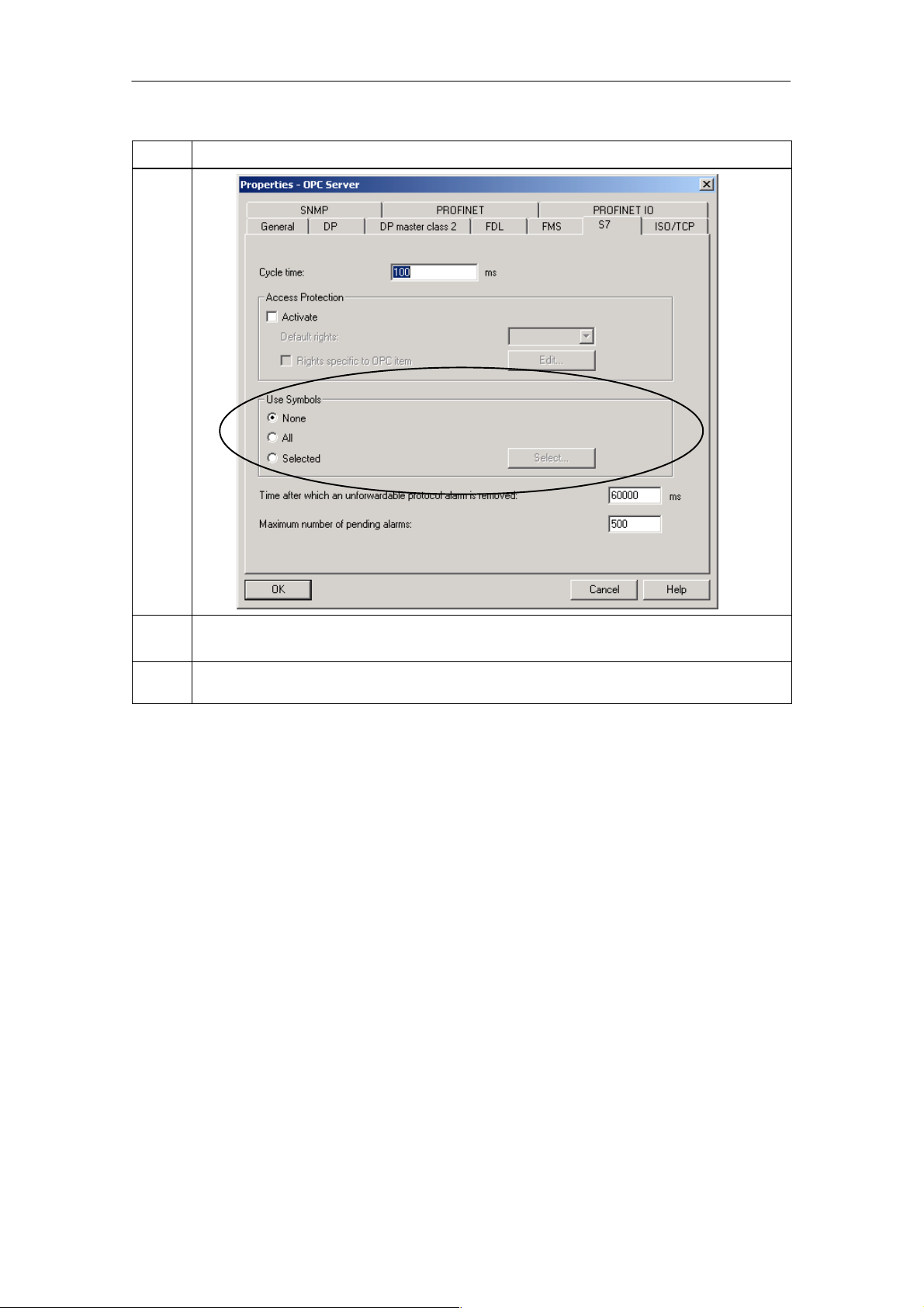
5.4 Using Symbols for S7 Connections 64. . . . . . . . . . . . . . . . . . . . . . . . . . . . .
5.5 Configuring OPC Properties for SNMP in Project Engineering 65. . . . . .
Commissioning PC Stations - Manual and Quick Start
8
Release 5/2005
C79000-G8976-C156-07
Page 9

5.5.1 Significance in SIMATIC NET 65. . . . . . . . . . . . . . . . . . . . . . . . . . . . . . . . . .
5.5.2 SNMP Traps 66. . . . . . . . . . . . . . . . . . . . . . . . . . . . . . . . . . . . . . . . . . . . . . . . .
6 Using the CP 1616 as a PROFINET IO Controller/Device 68. . . . . . . . . . . . . . . . . . .
6.1 Initialize CP 1616 (IP address and device name) 71. . . . . . . . . . . . . . . . .
6.2 Configuring the CP 1616 72. . . . . . . . . . . . . . . . . . . . . . . . . . . . . . . . . . . . . .
6.3 Example: Installing Linux Drivers (Suse Linux 9.2) 77. . . . . . . . . . . . . . . .
6.4 installing the PROFINET IO Sample Program (Suse Linux 9.2) 78. . . . .
Examples
7 Example — OPC Application for Industrial Ethernet 79. . . . . . . . . . . . . . . . . . . . . .
7.1 Overview 79. . . . . . . . . . . . . . . . . . . . . . . . . . . . . . . . . . . . . . . . . . . . . . . . . . . .
7.2 Hardware and Software Installation 81. . . . . . . . . . . . . . . . . . . . . . . . . . . . .
7.3 Creating the STEP 7 Project 82. . . . . . . . . . . . . . . . . . . . . . . . . . . . . . . . . . .
7.3.1 STEP 7 Project Engineering on a Central Engineering Station 82. . . . . .
7.3.2 Using Symbol Files 83. . . . . . . . . . . . . . . . . . . . . . . . . . . . . . . . . . . . . . . . . . .
Contents
7.4 Configuring the PC Station 86. . . . . . . . . . . . . . . . . . . . . . . . . . . . . . . . . . . .
7.5 Using the OPC Scout 90. . . . . . . . . . . . . . . . . . . . . . . . . . . . . . . . . . . . . . . . .
7.5.1 Establishing a Connection to the Server 90. . . . . . . . . . . . . . . . . . . . . . . . .
7.5.2 Inserting a Group and Variables 91. . . . . . . . . . . . . . . . . . . . . . . . . . . . . . . .
7.5.3 Displaying and Modifying Values of Variables 93. . . . . . . . . . . . . . . . . . . . .
8 Example — OPC Application for PROFIBUS-DP 94. . . . . . . . . . . . . . . . . . . . . . . . . .
8.1 Overview 94. . . . . . . . . . . . . . . . . . . . . . . . . . . . . . . . . . . . . . . . . . . . . . . . . . . .
8.2 Hardware and Software Installation 96. . . . . . . . . . . . . . . . . . . . . . . . . . . . .
8.3 Configuring the PC Station 97. . . . . . . . . . . . . . . . . . . . . . . . . . . . . . . . . . . .
8.4 Changing the configuration on the PC station 100. . . . . . . . . . . . . . . . . . . .
8.4.1 Changing the Hardware Configuration - Preparations 100. . . . . . . . . . . . .
8.4.2 Inserting a DP Master System 102. . . . . . . . . . . . . . . . . . . . . . . . . . . . . . . . .
8.4.3 Inserting a DP Slave 103. . . . . . . . . . . . . . . . . . . . . . . . . . . . . . . . . . . . . . . . . .
8.5 Using the OPC Scout 105. . . . . . . . . . . . . . . . . . . . . . . . . . . . . . . . . . . . . . . . .
8.5.1 Establishing a Connection to the Server 105. . . . . . . . . . . . . . . . . . . . . . . . .
8.5.2 Inserting Groups and Variables 106. . . . . . . . . . . . . . . . . . . . . . . . . . . . . . . . .
8.5.3 Displaying and Modifying Values of Variables 107. . . . . . . . . . . . . . . . . . . . .
9 Example — Unspecified Connection from a PC Application 109. . . . . . . . . . . . . . .
9.1 Overview 109. . . . . . . . . . . . . . . . . . . . . . . . . . . . . . . . . . . . . . . . . . . . . . . . . . . .
9.2 Installing the Software 110. . . . . . . . . . . . . . . . . . . . . . . . . . . . . . . . . . . . . . . .
9.3 Configuring the PC Station 111. . . . . . . . . . . . . . . . . . . . . . . . . . . . . . . . . . . .
9.4 Creating, Editing and Downloading a STEP 7 Project 116. . . . . . . . . . . . . .
9.4.1 Creating a New Project 116. . . . . . . . . . . . . . . . . . . . . . . . . . . . . . . . . . . . . . . .
9.4.2 Edit the Network and Connection Project Engineering Data 118. . . . . . . .
9.4.3 Downloading the Project Engineering Configuration 124. . . . . . . . . . . . . . .
Commissioning PC Stations - Manual and Quick Start
Release 5/2005
C79000-G8976-C156-07
9
Page 10

Contents
9.5 Configuration Console 126. . . . . . . . . . . . . . . . . . . . . . . . . . . . . . . . . . . . . . . .
10 Example — SNMP Communication with OPC 128. . . . . . . . . . . . . . . . . . . . . . . . . . .
10.1 Hardware and Software Installation 129. . . . . . . . . . . . . . . . . . . . . . . . . . . . .
10.2 Configuration of the SNMP OPC Server 130. . . . . . . . . . . . . . . . . . . . . . . . .
10.2.1 Editing the Plant Configuration 132. . . . . . . . . . . . . . . . . . . . . . . . . . . . . . . . .
10.3 Configuring the PC Station 135. . . . . . . . . . . . . . . . . . . . . . . . . . . . . . . . . . . .
10.4 Using the OPC Scout 138. . . . . . . . . . . . . . . . . . . . . . . . . . . . . . . . . . . . . . . . .
10.4.1 Establishing a Connection to the Server 138. . . . . . . . . . . . . . . . . . . . . . . . .
10.4.2 Inserting a Group 139. . . . . . . . . . . . . . . . . . . . . . . . . . . . . . . . . . . . . . . . . . . . .
10.4.3 Setting the Trap Recipient based on the Example of an OSM/ESM 141. .
10.5 Creating a Device Profile with the MIB Compiler 143. . . . . . . . . . . . . . . . . .
11 Example — PROFINET Communication with OPC 147. . . . . . . . . . . . . . . . . . . . . . .
11.1 Hardware and Software Installation 148. . . . . . . . . . . . . . . . . . . . . . . . . . . . .
11.2 Configuring the PC Station 149. . . . . . . . . . . . . . . . . . . . . . . . . . . . . . . . . . . .
11.3 Using Symbol Files 151. . . . . . . . . . . . . . . . . . . . . . . . . . . . . . . . . . . . . . . . . . .
Tools and Utilities
12 Station Configuration Editor Tool 153. . . . . . . . . . . . . . . . . . . . . . . . . . . . . . . . . . . . . .
12.1 Characteristics, Functions and Activation 153. . . . . . . . . . . . . . . . . . . . . . . .
12.2 Managing Components: “Components” Tab 154. . . . . . . . . . . . . . . . . . . . . .
12.3 Evaluating Messages: “Diagnostics” Tab 158. . . . . . . . . . . . . . . . . . . . . . . . .
12.4 Setting the Station Configuration Editor: “Properties” Dialog 158. . . . . . . .
13 SIMATIC NCM PC Project Engineering Tool 160. . . . . . . . . . . . . . . . . . . . . . . . . . . . .
13.1 Characteristics, Functions and Activation 160. . . . . . . . . . . . . . . . . . . . . . . .
13.2 Relationship Between SIMATIC NCM PC and STEP 7 163. . . . . . . . . . . .
13.3 Creating a PC Station 165. . . . . . . . . . . . . . . . . . . . . . . . . . . . . . . . . . . . . . . . .
13.4 Configuring a PC Station with SIMATIC NCM PC Config 168. . . . . . . . . . .
13.5 Creating the DP Master System 171. . . . . . . . . . . . . . . . . . . . . . . . . . . . . . . .
13.6 Creating a PROFINET IO System 173. . . . . . . . . . . . . . . . . . . . . . . . . . . . . .
13.7 Configuring Connections 175. . . . . . . . . . . . . . . . . . . . . . . . . . . . . . . . . . . . . .
13.8 Project Engineering for a PC Station as DP Slave 177. . . . . . . . . . . . . . . .
13.8.1 DP Master is Known in NCM / STEP 7 177. . . . . . . . . . . . . . . . . . . . . . . . . .
13.8.2 Configuration with a “Third-party” DP Master 182. . . . . . . . . . . . . . . . . . . .
13.9 Downloading Project Engineering Data to the PC Station (after Initial
Configuration) 184. . . . . . . . . . . . . . . . . . . . . . . . . . . . . . . . . . . . . . . . . . . . . . . .
13.9.1 Online Mode 185. . . . . . . . . . . . . . . . . . . . . . . . . . . . . . . . . . . . . . . . . . . . . . . . .
13.9.2 Offline Mode (Engineering Station and Runtime PC Separate) - XDB Import 187
Commissioning PC Stations - Manual and Quick Start
10
C79000-G8976-C156-07
Release 5/2005
Page 11

13.10 Adapting Mismatched Configurations 189. . . . . . . . . . . . . . . . . . . . . . . . . . . .
14 PC Station Wizard 190. . . . . . . . . . . . . . . . . . . . . . . . . . . . . . . . . . . . . . . . . . . . . . . . . . . . .
15 Symbol File Configurator Too 192. . . . . . . . . . . . . . . . . . . . . . . . . . . . . . . . . . . . . . . . . .
15.1 Characteristics, Functions and Activation 192. . . . . . . . . . . . . . . . . . . . . . . .
15.2 The Meaning of Symbols 195. . . . . . . . . . . . . . . . . . . . . . . . . . . . . . . . . . . . . .
15.3 Menus of the Symbol File Configurator in Detail 197. . . . . . . . . . . . . . . . . .
15.4 Managing Symbols 199. . . . . . . . . . . . . . . . . . . . . . . . . . . . . . . . . . . . . . . . . . .
15.4.1 How to Insert a New Symbol 199. . . . . . . . . . . . . . . . . . . . . . . . . . . . . . . . . . .
15.4.2 How to Insert a New Folder 200. . . . . . . . . . . . . . . . . . . . . . . . . . . . . . . . . . . .
15.4.3 How to Add a Name Space Prefix 201. . . . . . . . . . . . . . . . . . . . . . . . . . . . . .
15.4.4 How to Delete Folders or Symbols 201. . . . . . . . . . . . . . . . . . . . . . . . . . . . . .
15.4.5 How to Import a Symbol File 201. . . . . . . . . . . . . . . . . . . . . . . . . . . . . . . . . . .
15.4.6 How to Export a Symbol File 202. . . . . . . . . . . . . . . . . . . . . . . . . . . . . . . . . . .
16 Configuration Console Tool 203. . . . . . . . . . . . . . . . . . . . . . . . . . . . . . . . . . . . . . . . . . .
16.1 Characteristics, Function and Activation 203. . . . . . . . . . . . . . . . . . . . . . . . .
16.2 Support During Commissioning and Operation 205. . . . . . . . . . . . . . . . . . .
16.2.1 Triggering a Restart on the Module 205. . . . . . . . . . . . . . . . . . . . . . . . . . . . .
16.2.2 Forcing the OPC Server to Close Down 207. . . . . . . . . . . . . . . . . . . . . . . . .
16.2.3 Activating Configured Protocols Step by Step 209. . . . . . . . . . . . . . . . . . . .
16.2.4 Setting a Symbol File for OPC 211. . . . . . . . . . . . . . . . . . . . . . . . . . . . . . . . .
16.2.5 Setting Traces 213. . . . . . . . . . . . . . . . . . . . . . . . . . . . . . . . . . . . . . . . . . . . . . .
16.2.6 Language Setting 217. . . . . . . . . . . . . . . . . . . . . . . . . . . . . . . . . . . . . . . . . . . .
16.2.7 Automatic Startup of Applications and Services; 218. . . . . . . . . . . . . . . . . .
16.2.8 Security Setting (Windows XP + SP2 only) 221. . . . . . . . . . . . . . . . . . . . . . .
16.2.9 Configuration Examples 223. . . . . . . . . . . . . . . . . . . . . . . . . . . . . . . . . . . . . . .
Contents
16.3 Editing the Configuration 224. . . . . . . . . . . . . . . . . . . . . . . . . . . . . . . . . . . . . .
16.3.1 Changing the Mode of a Module 224. . . . . . . . . . . . . . . . . . . . . . . . . . . . . . . .
16.3.2 Displaying and Setting the Industrial Ethernet Network Parameters for a CP
1613 226. . . . . . . . . . . . . . . . . . . . . . . . . . . . . . . . . . . . . . . . . . . . . . . . . . . . . . . .
16.3.3 Setting the Industrial Ethernet Station Addresses 228. . . . . . . . . . . . . . . . .
16.3.4 Assigning Access Points to the Individual Modules 229. . . . . . . . . . . . . . . .
16.3.5 Setting the PROFIBUS DP Slave 231. . . . . . . . . . . . . . . . . . . . . . . . . . . . . . .
16.4 Diagnostics with “Configuration Console” 233. . . . . . . . . . . . . . . . . . . . . . . .
16.4.1 Displaying the Operability of a PROFIBUS Module 233. . . . . . . . . . . . . . . .
16.4.2 Displaying the Industrial Ethernet Network Parameters for a CP 1613 235
16.4.3 Displaying PROFIBUS Network Nodes 236. . . . . . . . . . . . . . . . . . . . . . . . . .
16.4.4 Displaying PROFIBUS Network Parameters 238. . . . . . . . . . . . . . . . . . . . .
16.4.5 Displaying Version Information of Hardware and Firmware 239. . . . . . . . .
17 OPC Scout 240. . . . . . . . . . . . . . . . . . . . . . . . . . . . . . . . . . . . . . . . . . . . . . . . . . . . . . . . . . .
17.1 Characteristics, Functions and Activation 240. . . . . . . . . . . . . . . . . . . . . . . .
17.2 Connecting the OPC Scout to a Local Server 242. . . . . . . . . . . . . . . . . . . .
17.3 Connecting the OPC Scout to a Remote Server 242. . . . . . . . . . . . . . . . . .
17.4 Create a Group 243. . . . . . . . . . . . . . . . . . . . . . . . . . . . . . . . . . . . . . . . . . . . . .
17.5 Browsing the Process Space - OPC Navigator 243. . . . . . . . . . . . . . . . . . .
Commissioning PC Stations - Manual and Quick Start
Release 5/2005
C79000-G8976-C156-07
11
Page 12

Contents
17.6 Create New Variables 245. . . . . . . . . . . . . . . . . . . . . . . . . . . . . . . . . . . . . . . . .
17.7 Adding and Monitoring Variables 245. . . . . . . . . . . . . . . . . . . . . . . . . . . . . . .
17.8 Customizing the Display 246. . . . . . . . . . . . . . . . . . . . . . . . . . . . . . . . . . . . . . .
17.9 Display Attributes 247. . . . . . . . . . . . . . . . . . . . . . . . . . . . . . . . . . . . . . . . . . . .
17.10 Change Values 248. . . . . . . . . . . . . . . . . . . . . . . . . . . . . . . . . . . . . . . . . . . . . . .
17.11 Menus of the OPC Scout in Detail 248. . . . . . . . . . . . . . . . . . . . . . . . . . . . . .
17.11.1 File Menu 248. . . . . . . . . . . . . . . . . . . . . . . . . . . . . . . . . . . . . . . . . . . . . . . . . . .
17.11.2 View Menu 249. . . . . . . . . . . . . . . . . . . . . . . . . . . . . . . . . . . . . . . . . . . . . . . . . .
17.11.3 Server Menu 249. . . . . . . . . . . . . . . . . . . . . . . . . . . . . . . . . . . . . . . . . . . . . . . . .
17.11.4 Group Menu 250. . . . . . . . . . . . . . . . . . . . . . . . . . . . . . . . . . . . . . . . . . . . . . . . .
17.11.5 Item Menu 250. . . . . . . . . . . . . . . . . . . . . . . . . . . . . . . . . . . . . . . . . . . . . . . . . . .
17.11.6 ? Menu 251. . . . . . . . . . . . . . . . . . . . . . . . . . . . . . . . . . . . . . . . . . . . . . . . . . . . .
18 DCOM Settings with the dcomcnfg System Program 252. . . . . . . . . . . . . . . . . . . . .
18.1 Characteristics, Functions and Activation 252. . . . . . . . . . . . . . . . . . . . . . . .
18.2 ”Default Properties” Tab 255. . . . . . . . . . . . . . . . . . . . . . . . . . . . . . . . . . . . . . .
18.3 ”Default Security” / ”Default COM Security” / ”COM Security” Tab 257. . .
18.4 DCOM Configuration / “Applications” Tab 260. . . . . . . . . . . . . . . . . . . . . . . .
18.5 “Default Protocols” Tab 261. . . . . . . . . . . . . . . . . . . . . . . . . . . . . . . . . . . . . . . .
18.6 Configuration of the Server Computer 262. . . . . . . . . . . . . . . . . . . . . . . . . . .
18.6.1 “General” Tab: Registering the OPC Server 263. . . . . . . . . . . . . . . . . . . . . .
18.6.2 “Location” Tab 264. . . . . . . . . . . . . . . . . . . . . . . . . . . . . . . . . . . . . . . . . . . . . . .
18.6.3 “Identity” Tab 265. . . . . . . . . . . . . . . . . . . . . . . . . . . . . . . . . . . . . . . . . . . . . . . .
18.6.4 “Security” Tab 267. . . . . . . . . . . . . . . . . . . . . . . . . . . . . . . . . . . . . . . . . . . . . . . .
18.7 Configuration of the Client Computer 273. . . . . . . . . . . . . . . . . . . . . . . . . . . .
A Notes for Users of Older Versions 266. . . . . . . . . . . . . . . . . . . . . . . . . . . . . . . . . . . . . . .
A.1 LDB and XDB Databases - Overview 266. . . . . . . . . . . . . . . . . . . . . . . . . . .
A.2 Project Engineering up to SIMATIC NET CD 05/2000 267. . . . . . . . . . . . .
A.3 Continued Use of Previous Project Engineering 269. . . . . . . . . . . . . . . . . .
A.4 Industrial Ethernet - Effects on Older Product Versions
(SIMATIC NET CD 05/2000 and earlier) 270. . . . . . . . . . . . . . . . . . . . . . . . .
A.5 PROFIBUS - Effects on Older Product Versions
(SIMATIC NET CD 05/2000 and earlier) 272. . . . . . . . . . . . . . . . . . . . . . . . .
B Description of the PROFINET Configuration File 276. . . . . . . . . . . . . . . . . . . . . . . . .
C References and Literature 281. . . . . . . . . . . . . . . . . . . . . . . . . . . . . . . . . . . . . . . . . . . . . .
D Glossary 284. . . . . . . . . . . . . . . . . . . . . . . . . . . . . . . . . . . . . . . . . . . . . . . . . . . . . . . . . . . . . .
12
Commissioning PC Stations - Manual and Quick Start
C79000-G8976-C156-07
Release 5/2005
Page 13

1 Welcome to Advanced PC Configuration
1 Welcome to Advanced PC Configuration
1.1 A New Concept for Your Benefit
Advanced PC Configuration is the new tool with which you can commission a PC
station as part of an industrial communication network.
SIMATIC NET supports the option of using Advanced PC Configuration on a
central engineering station (ES) to configure not only PC stations but also, for
example, operator stations (OS). The engineering station is a networked PC with
the SIMATIC NCM PC program or STEP 7 installed.
Characteristics - Comparison with Previous Products
The new features of the SIMATIC NET software involve several changes to the
previous configuration and project engineering procedures and these are
summarized below:
S You can make all settings with one tool during project engineering and
download them completely to the PC station.
The tool is SIMATIC NCM PC or STEP 7. Depending on your system
configuration, you also use the Station Configuration Editor during the initial
configuration.
The functions of these two tools are now so clearly delineated that you no
longer need the aid of a further tool the Commissioning Wizard.
S Properties that you previously configured using the “Set PG/PC Interface”
program are now part of the project engineering and are downloaded to the PC
station. These include, for example, the station address and the bus
parameters. It is no longer necessary to create several databases.
S Properties that were previously specified in various project engineering
programs are now configured in the project engineering in SIMATIC NCM PC /
STEP 7. Examples of such project engineering tools include COML S7, COM
PROFIBUS.
S Configuration parameters for the OPC Server that were previously stored in
TXT files are now configured in the project engineering in SIMATIC NCM PC /
STEP 7 and downloaded to the PC station.
S The OPC server can also handle communication on unconfigured S7
connections in PG operation. This function is, for example, required for use in
HMI stations.
Supported Modules
You will find a list of modules supported and not supported by Advanced PC
Configuration in the “hinw_e.rtf” file on the SIMATIC NET product CD (<CD drive>
/ sw / cdintern / hinw_e.rtf).
Commissioning PC Stations - Manual and Quick Start
Release 5/2005
C79000-G8976-C156-07
13
Page 14

1 Welcome to Advanced PC Configuration
LDB Databases no Longer Required
By configuring on a central station and with the option of downloading, LDB
databases are no longer required for the DP, FMS, and S7 protocols. Configuration
and project engineering data can be exported to XDB files in STEP 7; they must
be imported into the central data management on the PC station using the Station
Configuration Editor.
Note
For more detailed information on the differences compared with the previous
procedure and handling the software and modules, refer to Appendix A.
14
Commissioning PC Stations - Manual and Quick Start
C79000-G8976-C156-07
Release 5/2005
Page 15

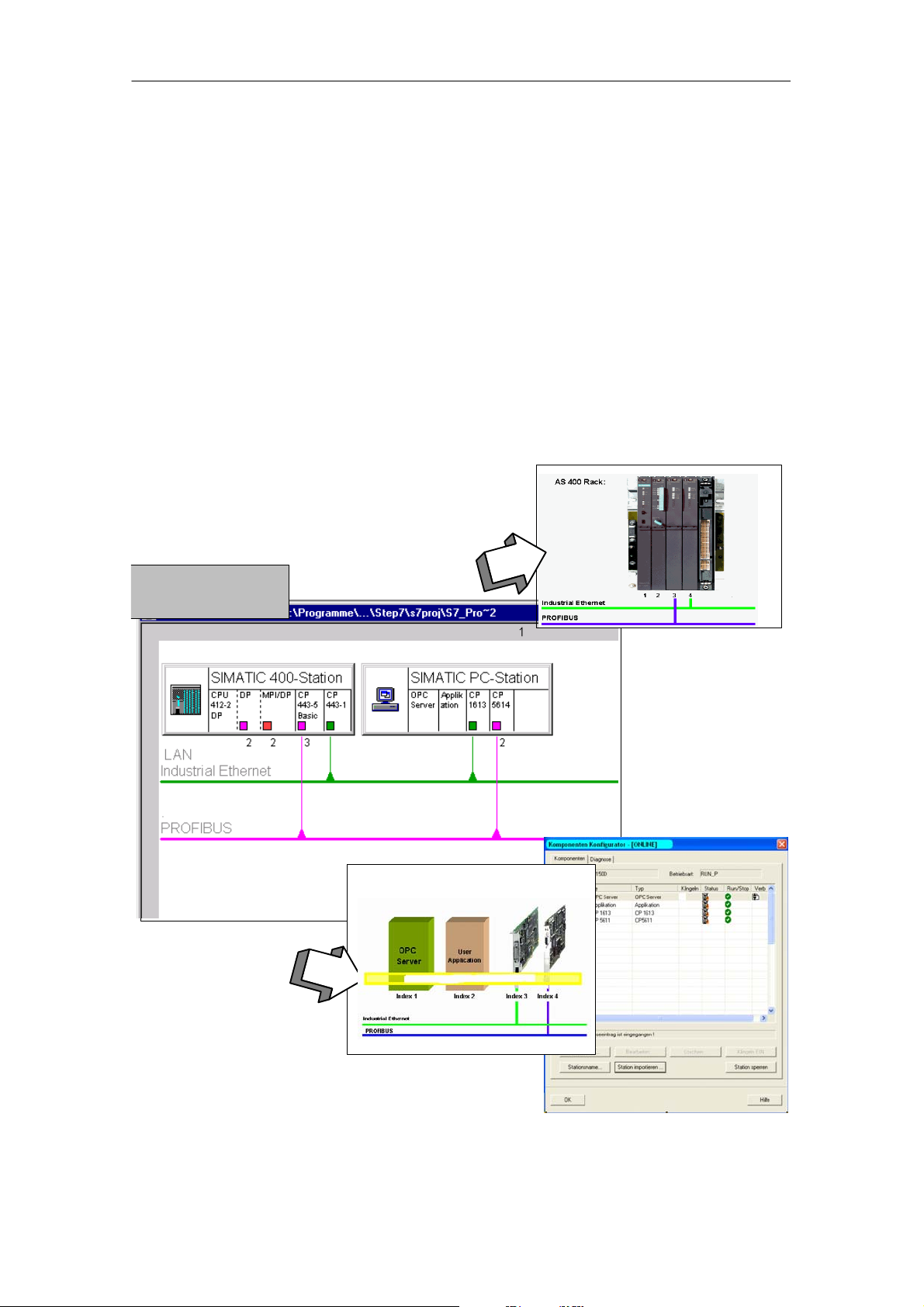
1.2 PC Stations in SIMATIC
Use of PCs in Automation
A “PC station” is a PC with communication modules and software components
within an automation solution with SIMATIC.
The hardware configuration of a PC station can be compared with the configuration
of an S7 controller In SIMATIC:
In an SIMATIC S7-400,
modules are inserted in the
slots in the rack.
1 Welcome to Advanced PC Configuration
In the same way, components of
a PC station, for example
modules, are assigned to a
virtual slot per software.
The virtual rack is implemented
on the PC station by software.
Virtual rack in the PC stationVirtual rack in the PC station
PC Station
Software - The OPC Server as Central Component
A PC station contains SIMATIC NET communication modules and software
applications. One typical software application with which user programs can
communicate is the SIMATIC NET OPC server.
Slot
Commissioning PC Stations - Manual and Quick Start
Release 5/2005
C79000-G8976-C156-07
15
Page 16
1 Welcome to Advanced PC Configuration
Uniform Engineering Environment
The PC station is handled just like a SIMATIC S7 controller during project
engineering with STEP 7 / NCM PC: You connect the S7 stations and PC stations
to the network in the network view and specify communication connections.
The project engineering data is downloaded to the stations at the touch of a button.
With PC stations, you have two options:
S Remote Configuration and Download:
Direct initial configuration or modification of a configuration and transfer of
project engineering data to an (online) PC station over an Ethernet adapter.
S Load a PC Station (XDB import)
In this situation, project engineering data is saved to a file and can be imported
into the PC station using any method of data transfer (applies to PROFIBUS
and Ethernet).
Project engineering
tool STEP 7 /
NCM PC
S Remote
Configuration /
Download
S Load a PC
Station
(XDB import)
S Download
Virtual rack in the PC station
16
Commissioning PC Stations - Manual and Quick Start
C79000-G8976-C156-07
Release 5/2005
Page 17

Index for Every Component
To allow communication between the components in the PC station and to receive
project engineering data, each component is assigned a unique identification
number. The identification number for modules, applications, and other
components in a PC station is the index. Analogous to the slot of a module in an
S7-400 controller, the index corresponds to a virtual slot in a PC station.
Note
Be careful not to confuse this “index” with a hardware slot, for example on the PCI
bus of the computer. The slot on the PCI bus is not relevant for commissioning
and is not used at any point.
1 Welcome to Advanced PC Configuration
Commissioning PC Stations - Manual and Quick Start
Release 5/2005
C79000-G8976-C156-07
17
Page 18
1 Welcome to Advanced PC Configuration
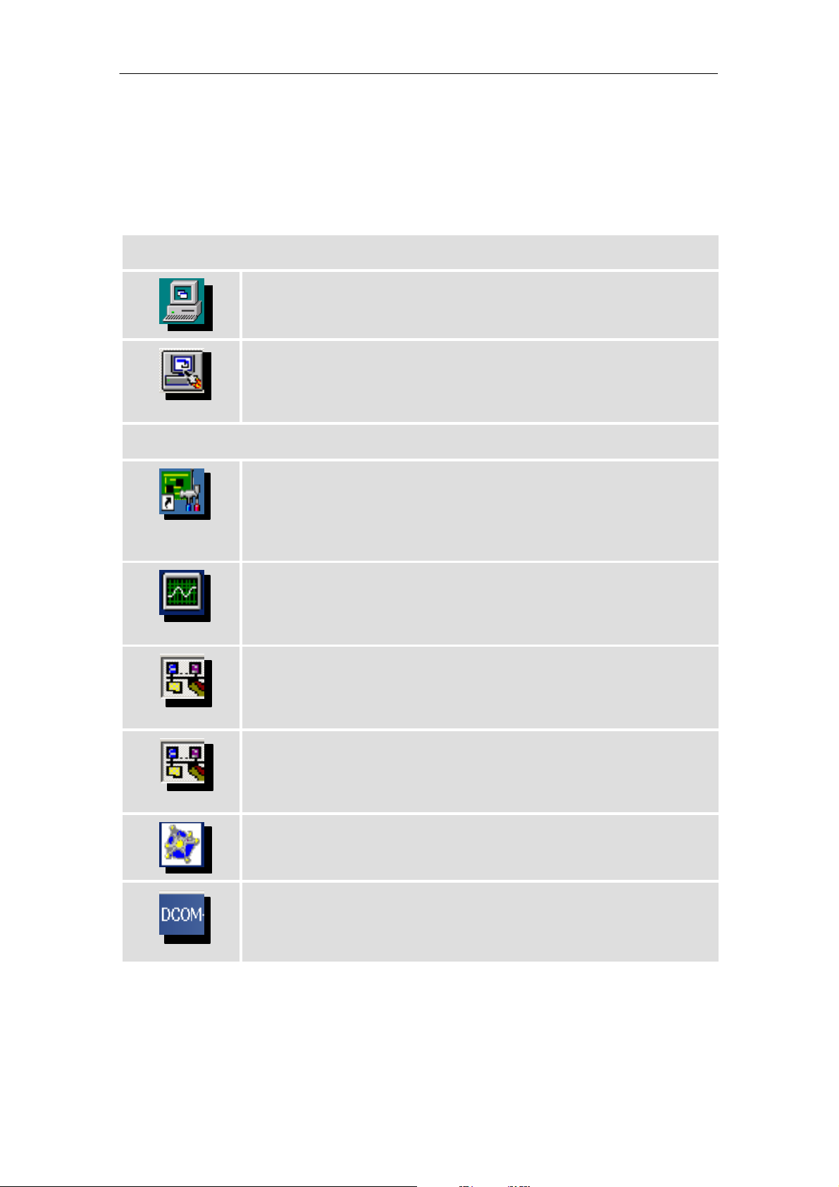
1.3 A Brief Introduction to Tools and Utilities
Once you have installed the SIMATIC NET software, you have the following tools
available:
Basic tools:
Station Configuration Editor
With this tool, you insert the modules and components into the “virtual”
slots of the PC station and assign them addresses and parameters.
Project engineering tool SIMATIC NCM PC
SIMATIC NCM PC is a version of STEP 7 specially for project engineering
of PC stations. It provides the full range of features of STEP 7 for PC
stations.
Additional tools / utilities:
PC Station Wizard
The PC Station Wizard supports you when creating projects in SIMATIC
NCM PC or STEP 7. It allows the automatic adoption of configuration on
the local PC station. This helps you to make sure that your configuration
data is consistent.
Symbol File Configurator
With the Symbol File Configurator, you can create symbol files that allow
you the option of access to symbolic variables over the SIMATIC NET
OPC server.
Configuration Console
The Configuration Console provides a variety of options for configuration
and diagnostics of PC hardware components and PC user programs as
well as the OPC server.
SIMATIC NET Information Service
The information service displays information on events that occurred due
to activated trace requests. Trace requests can be made in the
Configuration Console.
OPC Scout
With the OPC Scout, you can test an OPC application or commission the
OPC server.
18
DCOM Settings (Windows system program)
To allow a client to use a COM object on another computer, the properties
of the COM object must be configured on the client and on the remote
computer.
Commissioning PC Stations - Manual and Quick Start
C79000-G8976-C156-07
Release 5/2005
Page 19

1 Welcome to Advanced PC Configuration
mode
1.4 Guide to Installation and Commissioning
Before you start commissioning, you should clarify the area of operation of your
PC station and select the required mode for your communication module. The
steps involved in commissioning differ depending on the mode you select for your
communication module.
Below, you can see an overview of the steps involved in commissioning. The
sections following then describe the individual steps and tools in greater detail.
1.4.1 PG Operation or Configured Mode - Considerations
When commissioning and operating a SIMATIC PC station, distinctions must be
made between the following areas of application: Depending on the area of
application, select the mode of the communication module.
S PG Operation
This is the default mode for a programming device (PG/PC) and HMI station.
S Configured Mode
This mode should be selected for productive communication between
applications in the PC station and the programmable controllers, for example
SIMATIC S7-400.
The primary use of your PC station
is:
S For diagnostics and maintenance
and for programming and project
engineering (STEP 7).
S For process control tasks (operator
control and monitoring).
It should be possible to use the
station independent of a STEP 7
project.
S For project engineering (STEP 7) in
an automated plant operated with
S7 stations
S For tasks in process control and
visualization.
S As an automation system
networked with programmable
controllers.
resulting area of
application:
Programming
device (PG/PC)
HMI station
Engineering
station (ES)
Runtime PC
Selectable mode:
PG operation
(default)
Configured
mode
Commissioning PC Stations - Manual and Quick Start
Release 5/2005
C79000-G8976-C156-07
19
Page 20

1 Welcome to Advanced PC Configuration
Mixed operation is possible.
Since you can set the mode for individual communication modules, you can also
use the PC station in mixed operation.
Mixed operation, in this sense, means the use of several communications modules
some in the configured and some in the PG mode.
Depending on the selected mode, the information below applies to the individual
modules of the PC station.
Characteristics of the Selectable Modes
The table below shows the differences between the two selectable modes and how
this affects handling of the PC station during commissioning and operation.
Table 1-1
Mode
PG operation (default
mode)
Configured mode The PC station along with the modules planned in the project engineering is
Characteristics/Advantages when Commissioning and During
Operation
The module used in a PC station in this mode is not included in the STEP 7
project (it is, however, possible to take this module into account in the bus
parameter calculation using the PG/PC station object).
If your module in the PG or engineering station is configured for this mode,
you must specify the interface on the PG or the engineering station explicitly
with the “Set PG/PC Interface” or Configuration Console tool.
With HMI stations, connections to communication partners are set up for
process control over unconfigured S7 connections.
included in a STEP 7 project so that the communication relations with the
stations can be planned in the project.
This has the following advantages:
S Very simple commissioning (initial configuration) by using this
configuration.
S Networking parameters stored in the project are adopted (PROFIBUS).
20
Commissioning PC Stations - Manual and Quick Start
C79000-G8976-C156-07
Release 5/2005
Page 21
1 Welcome to Advanced PC Configuration
1.4.2 Commissioning for PG Operation - Overview
PG operation is the default mode for programming devices (PG/PC) and HMI
stations.
Step How does it work? Tool
1. Installing SIMATIC
NET software
2. Installing the
hardware (PC
modules)
3. Configuration for PG
operation
Install the SIMATIC NET software
based on the installation instructions
Install the communication module in the
PC station
Assign addresses and interface
parameters to the modules
Result:
PC station ready for PG/PC operation
SIMATIC NET CD / Windows
Configuration Console
Set PG/PC Interface
Next step for HMI stations only:
4. Configuration for HMI
stations
5. Testing the
configuration
Specify the access points for the
applications
Configuration Console Configuration Console
Configuration Console
Set PG/PC Interface
Result:
HMI station and applications ready for operation
Communication over unconfigured S7 connections is possible.
Commissioning PC Stations - Manual and Quick Start
Release 5/2005
C79000-G8976-C156-07
21
Page 22

1 Welcome to Advanced PC Configuration
1.4.3 Commissioning for Configured Mode - Overview
When commissioning in the configured mode, three situations can be
distinguished. The situation depends on whether or not project engineering data is
already available in the form of an XDB file or whether commissioning is
independent of project engineering (no XDB file).
Initial configuration means the step in commissioning at which the module is
switched to “configured mode” and obtains addresses and network parameters .
S Case aInitial Configuration by Remote Configuration with STEP 7 / NCM
PC
With this method, it is assumed that the PC station and its components and
applications is first created in project engineering in STEP 7 / NCM PC. The
target PC station that can be reached over an Ethernet adapter (online) is then
configured remotely over STEP 7 / NCM PC (applies to Ethernet and
PROFIBUS).
The advantage of this is that the project engineering data and the PC
configuration are consistent and the total effort is minimal.
Step How does it work? Tool
1. Installing SIMATIC
NET Software on the
Engineering PC/PG
and on the PC Station
2. Installing the
hardware (PC
modules)
3. Project Engineering
on the PC Station
Install the SIMATIC NET software
based on the installation instructions
Install the communication module in the
PC station
Steps in project engineering of the PC
station:
S Create the PC station in NCM PC
S Enter modules and applications S HW Config
S Create connections in NetPro
S Use symbols (in the project
engineering of the OPC server)
4. Initial configuration Remote configuration with the menu
command “PLC
5. Downloading the
Project Engineering
Data to the PC Station
Download the project engineering data
with the menu command ”PLC
Download”
Result:
PC station is ready for productive communication
"
Configure”
"
SIMATIC NET CD / Windows
Refer to the documentation on the
CP
NCM PC / STEP 7
S SIMATIC Manager
S NetPro
S HW Config
NCM PC / STEP7
NCM PC / STEP7
6. Testing the
configuration
22
Configuration Console Configuration Console
Commissioning PC Stations - Manual and Quick Start
C79000-G8976-C156-07
Release 5/2005
Page 23

S Case b) Initial configuration with existing project engineering (XDB file)
With this method, it is assumed that the PC station and its components and
applications is first created in project engineering in STEP 7 / NCM PC. This
produces a database (XDB file) that is then available for the commissioning
engineer for the initial configuration.
The advantage of this is that the project engineering data and the PC
configuration are consistent and the total effort is minimal.
Step How does it work? Tool
Project engineering
(as prerequirement for
initial configuration)
1 Welcome to Advanced PC Configuration
Steps in project engineering of the PC
station:
S Create the PC station in NCM PC
NCM PC / STEP 7
S SIMATIC Manager
S Enter modules and applications S HW Config
S Create connections in NetPro
S Use symbols (in the project
engineering of the OPC server)
S NetPro
S HW Config
S Project engineering data of the PC
station is saved in an XDB file .
1. Installing SIMATIC
NET software
2. Installing the
hardware (PC
modules)
3. Initial configuration Import XDB
4. Testing the
configuration
Install the SIMATIC NET software
based on the installation instructions
Install the communication module in the
PC station
Project engineering data is transferred
to the PC station.
Result:
PC station is ready for productive communication
Configuration Console Configuration Console
S SIMATIC Manager
SIMATIC NET CD / Windows
Refer to the documentation on the
CP
Station Configuration Editor
(later download of project
engineering data also possible
with NCM PC / STEP 7)
Commissioning PC Stations - Manual and Quick Start
Release 5/2005
C79000-G8976-C156-07
23
Page 24

1 Welcome to Advanced PC Configuration
S Case c) Initial configuration without existing project engineering (XDB
file)
This is, for example, the situation when the commissioning personnel do not
have an XDB file but the devices need to be installed in a plant and their
functionality checked.
Regardless of the initial configuration, the stations and their connections can be
(PC and PLC) can be set up in the project engineering. The project engineering
data is then transferred to the previously configured PC stations in the system.
Depending on the availability of the station, this is achieved by download or
loading the station (XDB import).
To ensure that the configuration on the PC station and the project engineering
are consistent, it is advisable to import the configuration data from the PC
station.
Step How does it work? Tool
1. Installing SIMATIC
NET software
2. Installing the
hardware (PC
modules)
3. Initial configuration Module configuration Station Configuration Editor
Install the SIMATIC NET software
based on the installation instructions
Install the communication module in the
PC station
SIMATIC NET CD / Windows
Refer to the documentation on the
CP
4. Testing the
configuration
5. optional:
Data export
6. Project engineering
(this is not dependent on
the previous steps that is
necessary for step 7.)
Result:
The PC station with its modules and
applications is configured and ready to
receive project engineering data
Configuration Console Configuration Console
Enter the configuration in a new
(temporary) STEP 7 project “PC
station”.
Steps in project engineering of the PC
station:
S Create the PC station in NCM PC
PC Station Wizard / NCM PC
NCM PC / STEP 7
S PC Station Wizard (local only)
/ SIMATIC Manager
S optional (see Step 5): Adopting the
configuration from the project
created in Step 5.
S Enter modules in applications
(identical to changes in the Station
Configuration Editor)
S Create connections in NetPro
S HW Config
S NetPro
S Use symbols (in the project
engineering of the OPC server)
24
Commissioning PC Stations - Manual and Quick Start
C79000-G8976-C156-07
Release 5/2005
Page 25

Step ToolHow does it work?
7. Downloading the
Project Engineering
Data to the PC Station
1 Welcome to Advanced PC Configuration
S for “offline mode”: Save project
engineering data of the PC station in
XDB.
Depending on how the PC station can
be reached:
S online: (local or remote) load project
engineering data on station
S HW Config / NetPro
S SIMATIC Manager
S Import XDB S Station Configuration Editor
Result:
PC station is ready for productive
communication
8. Testing the
configuration
Configuration Console Configuration Console
Commissioning PC Stations - Manual and Quick Start
Release 5/2005
C79000-G8976-C156-07
25
Page 26

2 Getting Started “Configured Mode”
2 Getting Started “Configured Mode”
The “configured mode” should be selected for productive communication between
applications in the PC station and the programmable controllers, for example
SIMATIC S7-400.
This chapter explains how to commission your PC station with communication
modules for this mode for the first time (initial configuration).
In conjunction with the project engineering, we will explain how to handle the data
exchange between the PC station and the project engineering tool.
Requirement: SIMATIC NET PC software and hardware are installed
Before you work through the steps described here, you must first install the
SIMATIC NET software and the hardware on your PC station.
S Installing SIMATIC NET PC Software
Follow the procedure described in the Installation Instructions that accompany
every SIMATIC NET PC module to install the products of the SIMATIC NET PC
Software CD.
The installed products are described in detail in the “Tools” section.
S Installing hardware (PC modules)
Install the hardware in your computer as described in the Installation
Instructions that accompany every module.
26
Commissioning PC Stations - Manual and Quick Start
C79000-G8976-C156-07
Release 5/2005
Page 27

2 Getting Started “Configured Mode”
2.1 Steps in Creating Project Engineering Data
To create the project engineering data, you use the SIMATIC NCM PC or SIMATIC
STEP 7 tool.
Why do we need project engineering data?
To allow the device networked in a plant to communicate, the devices must be
supplied with data on the components and the communication connections. Before
devices can go over to productive operation, the project engineering data must first
be created and loaded on the devices.
This project engineering includes not only the PLC such as SIMATIC S7 stations
but also the PC stations so that the communication relations between all devices of
the plant can be specified. This makes a consistency check and synchronization of
the elements of the system possible.
Apart from specifying the PLC and PC stations and their properties on the LAN,
project engineering also includes defining communication connections and
symbols for process variables on the OPC server.
Result
Once the project engineering data have been downloaded to or imported into the
PC station, the applications can communicate over the established communication
networks with the stations accessible over the network.
Initial Situation
S Case a) Initial configuration using remote configuration with STEP7 / NCM PC
To be able to make the initial configuration on the PC station (available online)
in the next step, you must first create the project engineering data for the PC
station with NCM PC / STEP 7.
S Case b) An XDB file for initial configuration is available
To be able to make the initial configuration in the next step, you must first
create the project engineering data for the PC station with NCM PC / STEP 7
and then make this data available in an XDB file.
S Case c) The initial configuration has already been made on the PC station
Project engineering data is downloaded or imported as an XDB file following
initial configuration.
Commissioning PC Stations - Manual and Quick Start
Release 5/2005
C79000-G8976-C156-07
27
Page 28

2 Getting Started “Configured Mode”
Follow the steps below:
Steps in Project Engineering
1. Start the SIMATIC NCM PC from the Start menu.
"
(Start
As an alternative if “online local” : Use the PC Station Wizard
If you want to create the project engineering database on the PC station you are configuring
(online local) and the initial configuration has been made, you can start the PC Station Wizard
as an alternative.
This gives you the option of adopting the configuration data created previously in the Station
Configuration Editor in a new or existing STEP 7 project.
Since we are assuming that we are commissioning the station for the first time, you can select
the following options provided by the PC Station Wizard:
SIMATIC "SIMATIC NCM PC).
S Editing a saved configuration
Open an existing project and compare the local configuration with the information in the
project. “
This adds the current PC station to a project in which, for example, project engineering data
for S7 stations already exists.
S Creating a new configuration
Create a new project and transfer the local configuration to the project.
Tip:
You can also select this option when you want to backup the project engineering data in an
archive. This archive file can be used on an engineering system in STEP 7.
2. Create a PC station in an existing or new project.
Note:
This is omitted when the data is entered by the PC Station Wizard or when an archived
configuration is used (see above).
28
Commissioning PC Stations - Manual and Quick Start
C79000-G8976-C156-07
Release 5/2005
Page 29
2 Getting Started “Configured Mode”
Steps in Project Engineering
3. Change to NCM PC Config / HW Config and enter the intended modules and applications (take
them from the catalog).
(omitted if data entered by the PC Station Wizard)
The software applications that use communication services directly must also be specified in
project engineering. One direct use is calling the protocol-specific function libraries. The OPC
server uses communication services directly and must be included in project engineering. OPC
clients only require indirect access via the OPC server and do not need to be configured in
project engineering.
4. Optional:
If symbol tables were created for S7 stations in your project, you can make them accessible to
the OPC server.
When you later import the XDB file or download the project engineering data to the PC station,
these symbol tables are included.
Open the properties dialog of the OPC server to make your selection:
Commissioning PC Stations - Manual and Quick Start
Release 5/2005
C79000-G8976-C156-07
29
Page 30
2 Getting Started “Configured Mode”
Steps in Project Engineering
5. Save the configuration.
(omitted if data entered by the PC Station Wizard)
6. Change to NetPro to network the station and to create the connections in the project
engineering.
30
Commissioning PC Stations - Manual and Quick Start
C79000-G8976-C156-07
Release 5/2005
Page 31

2 Getting Started “Configured Mode”
Steps in Project Engineering
Note:
You can create the S7 station shown in the screenshot only with STEP 7/HW Config.
In SIMATIC NCM PC, you can open and edit a project containing S7 stations. You can,
however, only create and download project engineering data for PC stations.
7. XDB export for offline mode:
When you save and compile the project, the project engineering data of the PC station is saved
in an XDB file.
Y ou will find information on the storage location of the XDB file in the “Configuration” tab in the
Properties PC Station dialog.
Commissioning PC Stations - Manual and Quick Start
Release 5/2005
C79000-G8976-C156-07
31
Page 32

2 Getting Started “Configured Mode”
Steps in Project Engineering
8. If the PC station is available online (local or remote), the next step is the initial configuration of
the station.
Note: To load the project engineering data locally, you must set the access point S7ONLINE for
the PC station to PC-internal (local).
Summary
In the “project engineering” step described here, the following activities were
explained:
1. Creating a STEP 7 project or using an existing STEP 7 project.
2. Creating a PC station in the STEP 7 project (NetPro / HW Config).
3. Inserting and networking PC modules in the PC station (HW Config/NetPro).
4. Creating applications (here the OPC server).
5. Creating the engineering data for connections between the applications.
6. Storing the project engineering data in an XDB database.
For offline mode, the XDB database is then available and can be used to import
the engineering data on the PC station.
32
Commissioning PC Stations - Manual and Quick Start
C79000-G8976-C156-07
Release 5/2005
Page 33

Where to go from here - optional activities
Once the project engineering configuration has been accepted, the PC station is
operational. The following steps allowing the use of symbols, diagnostics, and
calling the OPC Scout are optional. You should, however, check that the modules
in your PC station are operational using the diagnostic functions.
2 Getting Started “Configured Mode”
Commissioning PC Stations - Manual and Quick Start
Release 5/2005
C79000-G8976-C156-07
33
Page 34

2 Getting Started “Configured Mode”
2.2 Steps for Initial Configuration
For the initial configuration, use one of the following tools depending on the
procedure:
S Station Configuration Editor
S STEP 7 / NCM PC
Why do we need an initial configuration?
When a module is started up for the first time, it must be configured. This initial
configuration is necessary for all newly installed modules.
After the initial configuration of the modules, the PC station is prepared to receive
project engineering data. This step is comparable with inserting components in the
rack of an S7-400 station.
Result
When you start the PC station, the PC module of the PC station is initially in the
PG operation mode.
By adding the communication module in the Station Configuration Editor, the
module is automatically switched to the “configured mode” and the index (the
“virtual slot number”) of the module is set.
Interaction between Initial Configuration and Project Engineering
Depending on the area of application, two situations must be distinguished:
S Case a) Initial configuration using remote configuration with STEP7 / NCM PC
S Case b) Initial configuration with existing project engineering data (XDB file)
S Case c) Initial configuration without existing project engineering data (XDB file)
34
Commissioning PC Stations - Manual and Quick Start
C79000-G8976-C156-07
Release 5/2005
Page 35

2 Getting Started “Configured Mode”
2.2.1 Case a) Initial configuration using remote configuration with STEP 7 / NCM PC
The target PC station that is available online is configured directly with STEP7 /
NCM PC remote.
The advantage of this is that the project engineering data and the PC configuration
are consistent and the total effort is minimal. Address parameters are adopted
from the project engineering.
You can also transfer project engineering data to the PC station later by
downloading or loading the station (importing an XDB file).
Follow the steps below:
How to Make the ”Initial Configuration with an XDB File”
1. Select the PC station engineered in your STEP7 project.
2. Select the menu command “PLC " Configure” to open the “Configure: Zielrechner”
Commissioning PC Stations - Manual and Quick Start
Release 5/2005
C79000-G8976-C156-07
35
Page 36

2 Getting Started “Configured Mode”
How to Make the ”Initial Configuration with an XDB File”
3. Follow the instructions in the online help of the dialog to create and complete the remote
configuration.
Result:
The PC station with its modules and applications is configured and
ready to receive project engineering data
36
Commissioning PC Stations - Manual and Quick Start
C79000-G8976-C156-07
Release 5/2005
Page 37

2 Getting Started “Configured Mode”
2.2.2 Case b) Initial configuration with XDB file
In this case, you can import the XDB file with the project engineering data for the
PC station directly.
The advantage of this is that the project engineering data and the PC configuration
are consistent and the total effort is minimal. Address parameters are adopted
from the project engineering.
Follow the steps below:
How to Make the ”Initial Configuration with an XDB File”
1 Start the Station Configuration Editor from the Start menu.
"
(Start
SYSTRAY.
Y ou first see an empty configuration list.
2 Import the XDB file using the “Import Station...” button.
All the modules and applications specified in the project engineering are entered and displayed
in a window.
During import, all the project engineering data; in other words, station name, modules,
applications, communication connections, and symbols are entered in the PC station.
Importing is possible only when the imported configuration matches the existing local
configuration.
Station Configuration Editor) or by double-clicking on the icon in the Windows
Commissioning PC Stations - Manual and Quick Start
Release 5/2005
C79000-G8976-C156-07
37
Page 38

2 Getting Started “Configured Mode”
How to Make the ”Initial Configuration with an XDB File”
3 If you want to prevent project engineering data from being transferred online at a later point in
time, select the “Work offline...” option...”. The default is that project engineering data can be
transferred online.
Result:
PC station is ready for productive communication
S Module addresses are set;
S Communication connections configured in the project engineering
are established;
S Variables can be accessed using symbols configured in the project
engineering.
Tip:
You can also follow this procedure in the example “OPC Configuration for Industrial
Ethernet” in this manual; see Section 7.
Where to we go from here?
you can now use the other tools from SIMATIC NET for diagnostics,
commissioning, and testing.
See also Section 1.3.
38
Commissioning PC Stations - Manual and Quick Start
C79000-G8976-C156-07
Release 5/2005
Page 39

2 Getting Started “Configured Mode”
2.2.3 Initial configuration without XDB file
In this case, you specify the modules during initial configuration in the Station
Configuration Editor.
You can transfer project engineering data to the PC station later by downloading or
importing an XDB file.
You can also create project engineering data locally on the PC station and then
import it later into the engineering system (NCM PC). This makes it extremely
simple to create a configuration in the project engineering system that matches the
configuration on the real PC station.
Follow the steps below:
How to Make the Initial Configuration without an XDB File
1 Start the Station Configuration Editor from the Start menu.
"
(Start
SYSTRAY.
Y ou first see an empty configuration list.
2 Assign the station name using the “Station Name...” button.
3 In the next step, you enter the components.
Using the “Add...” button, select the module that will be put into “configured mode”. All the
modules installed in the local station are not yet configured are displayed for selection.
Caution:
If there are several Softnet PROFIBUS modules, only one can be configured in project
engineering.
Station Configuration Editor) or by double-clicking on the icon in the Windows
Commissioning PC Stations - Manual and Quick Start
Release 5/2005
C79000-G8976-C156-07
39
Page 40

2 Getting Started “Configured Mode”
How to Make the Initial Configuration without an XDB File
4 In the properties dialog that opens, give the module an address.
In some cases, you can also set further module parameters, for example bus parameters,
(mandatory with PROFIBUS).
5 Repeat the steps for all other modules that exist in the local station and that you want to
operate in configured mode.
6 Using the “Add” button, add the applications to be operated on the station.
7 Repeat the steps for all other applications you want to use for the configured mode.
Result:
PC station is configured with modules and applications and ready
to receive project engineering data (select online mode)
Tip:
You will also find this procedure in our example “OPC Configuration for
PROFIBUS”; see Section 8.
Where to we go from here?
In the next step, you supply the PC station with project engineering data.
40
Commissioning PC Stations - Manual and Quick Start
C79000-G8976-C156-07
Release 5/2005
Page 41

3 Getting Started “PG Operation”
3 Getting Started “PG Operation”
This chapter shows you how you can configure your PC module in PG operation.
In this situation, we distinguish two modes:
S Programming device (PG/PC)
S HMI stations
The default setting for the PC modules is PG operation.
Requirement: SIMATIC NET PC software and hardware are installed
Before you work through the steps described here, you must first install the
SIMATIC NET software and the hardware on your PC station.
S Installing SIMATIC NET PC software
Follow the procedure described in the Installation Instructions that accompany
every SIMATIC NET PC module to install the products of the SIMATIC NET PC
Software CD.
S Installing hardware (PC modules)
Install the hardware in your computer as described in the Installation
Instructions that accompany every module.
Commissioning PC Stations - Manual and Quick Start
Release 5/2005
C79000-G8976-C156-07
41
Page 42

3 Getting Started “PG Operation”
3.1 Configuration for PG Operation - Programming Device (PG/PC)
You configure a module using the “Set PG/PC Interface“ tool.
Follow the steps below:
How to Configure for PG Operation
1. You can start the configuration program from the Windows taskbar:
" SIMATIC " SIMATIC NET " Set PG/PC Interface.
Start
As an alternative you can also start it from the Control Panel:
"
Start
Settings " Control Panel " Set PG/PC Interface.
2. Assign the access point for your application to the module.
2.1 To make your module usable for STEP 7, follow the steps outlined below in the “Set PG/PC
Interface” configuration program:
Select the access point “S7ONLINE” in the “Access Point of the Application” list box. The
current assignment then appears at the bottom in the list box “Interface Parameter Assignment
Used”.
2.2 Select the required entry in the “Interface Parameter Assignment Used” list box. Some modules
offer alternatives, for example the CP 1613 as follows:
S If you use the TCP protocol - “CP1613(RFC1006)”,
S if you use the ISO protocol - ”CP1613(ISO)”
or CP 5613/CP 5614 as follows:
S Normal situation - “CP5613_5614(PROFIBUS)”,
S on an MPI chain - “CP5613_5614(MPI)”.
For further details on setting access points, refer to the section ”Tools”.
42
Commissioning PC Stations - Manual and Quick Start
C79000-G8976-C156-07
Release 5/2005
Page 43

3 Getting Started “PG Operation”
How to Configure for PG Operation
3. Set the required communication parameters.
With your module selected, you can click on “Properties” and then set the communication
parameters. In normal situations, the parameter settings do not need to be modified (for more
detailed information on the parameters, refer to the online help that you can display by clicking
the “Help” button in the Settings dialog).
For more information on certain module types, see below.
4. When you close the Properties window, you return to the start dialog of the “Set PG/PC
Interface” communication program.
5. Close the configuration program with the “OK” button.
The module is now set up for PG operation.
Note
Remember that by clicking on a module to make settings, it is possible to change
the assignment. If you have accidentally changed an assignment, make sure you
correct it again.
Setting Communication Parameters - Extra Information
Prior to operation, the following communications parameters must be set:
S For PROFIBUS modules (for example CP 5613, CP 5511, CP 5611, CP 5512):
- Programming device / PC is the only master on the bus
- Address
- Transmission rate
- Profile (depending on the application: DP for the DP protocol, otherwise the
fast setting “Standard” or the safe setting “Universal“)
S For CP 1613 TCP:
The IP address, subnet mask, and gateway address in the “Ethernet (MAC)
and IP Addresses” tab
S For SOFTNET TCP (for example CP 1512, CP 1612):
The IP address, subnet mask and gateway address must be set. You can do
this directly in the Windows Control Panel in “Network” or here using the
“Network Properties” button in the “TCP/IP Network” tab.
For CP1613 ISO and SoftNet ISO, it is not normally necessary to make any
communication parameter settings.
Please note that you can also use diagnostic functions by clicking the “Diagnostics”
button in the start dialog of “Set PG/PC Interface“.
Commissioning PC Stations - Manual and Quick Start
Release 5/2005
C79000-G8976-C156-07
43
Page 44

3 Getting Started “PG Operation”
3.2 Configuration for PG Operation - HMI Stations
You configure a module using the “Set PG/PC Interface” tool.
Initially the procedure is identical to configuration for PG operation - programming
device (PG/PC) as described in Section 3.1.
The communication module remains in “PG operation”; it is then configured so that
applications can communicate over communication interfaces without further
connection configuration in the project engineering.
The applications access the communication module using access points. If new
access points need to be entered, this can also be done with the “Set PG/PC
Interface“ or “Configuration Console” tools.
Finally, you use the OPC Scout to assign the required items and connection
parameters to the user program.
Setting Access Points - Follow the steps below:
How to Configure for HMI Operation
1. You start in the same way as described for commissioning for PG operation in the previous
section:
You can start the configuration program from the Windows taskbar:
" SIMATIC " SIMATIC NET " Set PG/PC Interface.
Start
As an alternative you can also start it from the Control Panel:
"
Start
Settings " Control Panel " Set PG/PC Interface.
2. Assign the access point for your application to the module.
Note: You can generally also select the “S7ONLINE” access point here.
44
Commissioning PC Stations - Manual and Quick Start
C79000-G8976-C156-07
Release 5/2005
Page 45

3 Getting Started “PG Operation”
How to Configure for HMI Operation
2.1 Select the access point in the “Access Point of the Application” list box. The current assignment
then appears at the bottom in the list box “Interface Parameter Assignment Used”.
2.2 If the suitable access point for your application is not present, click the “Select” button in the
“Add/Remove” field.
This opens the dialog in which you can add new access points. Example:
Commissioning PC Stations - Manual and Quick Start
Release 5/2005
C79000-G8976-C156-07
45
Page 46

3 Getting Started “PG Operation”
2.3 Confirm your entries.
How to Configure for HMI Operation
As an alternative, you can also specify new access points in the “Configuration Console” tool.
-> see “Tools”
2.4 In the “Interface Parameter Assignment Used“ list box (or “Assigned Interface Parameter
Assignment”), select the entry you require. Some modules offer alternatives, for example the
CP 1613 as follows:
S If you use the TCP protocol - “CP1613(RFC1006)”,
S If you use the ISO protocol - “CP1613(ISO)”,
or CP 5613/CP 5614 as follows:
S Normal situation - “CP5613_5614(PROFIBUS)”,
S on an MPI chain - “CP5613_5614(MPI)”.
For further details on setting access points, refer to the section ”Tools”.
3. Set the required communication parameters.
For more detailed information on the module-dependent settings, refer to the previous section
“Step: Configuration for PG operation - programming device (PG/PC)”.
4. When you close the Properties window, you return to the start dialog of the “Set PG/PC
Interface” communication program.
5. Close the configuration program with the “OK” button.
Note
Remember that by clicking on a module to make settings, it is possible to change
the assignment. If you have accidentally changed an assignment, make sure you
correct it again.
46
Commissioning PC Stations - Manual and Quick Start
C79000-G8976-C156-07
Release 5/2005
Page 47

3 Getting Started “PG Operation”
Entries in the Client Program
For communication without project engineering data as described here, all the data
of the partner device relevant for communication must be known. Apart from the
access point described above, this includes the connection name and the station
address. The necessary parameters are described in detail in the manual on OPC
/1/.
Below, we want to show you how to add the ITEM and its parameters to the user
program.
Adding items - Follow the steps below:
How to Configure for HMI Operation
1. Open the client program and create an item. In the OPC Scout program, open the input boxes
for inserting items by selecting “Add Item” in the context menu on the right-hand side of the
program window. Browsing for the unconfigured connection is not yet possible at this time.
2. Add item
Enter the item with the previously described parameters in the “Add Item” dialog and click on
the “Add Item” button. If the syntax is correct, the item appears in the name space under the
“S7” branch.
3.
Commissioning PC Stations - Manual and Quick Start
Release 5/2005
C79000-G8976-C156-07
47
Page 48

3 Getting Started “PG Operation”
After adding the item and as long as the item is active, the connection can be used
like a configured connection. This means that you can browse in the name space
and also add further items without using the syntax of the unconfigured connection.
All you need to do is specify the connection name, for example
S7:[S7_conn_1]MB1.
48
Commissioning PC Stations - Manual and Quick Start
C79000-G8976-C156-07
Release 5/2005
Page 49

4 Using Additional Functions - Special Features to Note
4 Using Additional Functions - Special
Features to Note
4.1 Checking the Configuration and Diagnostics
The “Configuration Console” tool is a central tool for access to the components and
data of the PC station during the following tasks:
S Commissioning and operation
S Editing the configuration
S Diagnostics
For more detailed information on the available functions, refer to the description in
Chapter 16 “Tools”.
4.2 Testing with the OPC Scout
If you use the OPC interface; in other words, you have used the OPC Server in the
project engineering configuration, you can check the functionality of your
communications system as the last step. With the OPC Scout, you have access to
all process variables accessible with the configured protocols and connections via
the OPC Server.
Using the OPC Scout, you can monitor the values of process variables, read
values explicitly, and write values. The OPC Scout displays the name space of the
variables consisting of configured communications connections and symbolic
names.
For more detailed information on the available functions, refer to the description in
Chapter 16 “Tools”.
Commissioning PC Stations - Manual and Quick Start
Release 5/2005
C79000-G8976-C156-07
49
Page 50

4 Using Additional Functions - Special Features to Note
4.2.1 Detecting Errors in Communication with the OPC Scout
Introduction
The OPC Scout shows you the status of the communication connections. This can
be done using the properties of process variables or using information variables.
You can then recognize when a partner device is not accessible.
Errors when Connecting with the OPC Server
S The locally installed OPC Server cannot be started.
Possible causes for this are as follows:
- The PC station is currently receiving a new configuration.
- By installing and OPC Server of another manufacturer that has not kept to
the guidelines laid down by the OPC Foundation common files have been
corrupted.
S The remote OPC Server is not accessible.
This can occur when using DCOM and can have various causes:
- The network connection is down.
- The DCOM configuration of the local and remote server is not correct.
- The remote server is not correctly installed or configured.
50
Commissioning PC Stations - Manual and Quick Start
C79000-G8976-C156-07
Release 5/2005
Page 51

Errors when Adding Variables
S Variable cannot be added
Adding some or all variables is denied in the Navigator of the OPC Scout.
Possible causes for this are as follows:
- The variable name entered does not have the correct syntax.
- When using symbolic variables: The symbol file does not match the project
engineering configuration.
- The access permissions for the variables are restricted: Neither read nor
write permissions.
S A protocol or connections are not visible
No protocols are visible in the left-hand window of the navigator or protocols or
connections are missing. Possible causes for this are as follows:
- Some of the required connections were not created during configuration in
the project engineering.
- A module configured in the project engineering does not exist or was not
correctly initialized.
4 Using Additional Functions - Special Features to Note
- The configuration data created in the project engineering configuration have
not yet been transferred or transfer was unsuccessful.
Checking the status of process variables
S Quality of the variables is “bad”.
In the table view of the process variables, the value “bad” is entered for some or
all variables in the “Quality” column. Possible reasons for this are as follows:
- The network connection to the partner device is down.
- The partner device is not configured in the project engineering.
- The bus parameters of the PC station and partner device do not match.
S The value of the information variable for the connections status is “Down”.
The information variable has the quality “good”, however, the value is not “Up”.
These variables are generated by the OPC Server and always have the quality
“good”. The possible reasons for the value on the variable identical to those for
quality = “bad”.
Commissioning PC Stations - Manual and Quick Start
Release 5/2005
C79000-G8976-C156-07
51
Page 52

4 Using Additional Functions - Special Features to Note
4.3 Further Functions / Special Features
4.3.1 Adopting the Project Engineering and Symbols from PROFINET iMap and SIMOTION Scout
You can also use the symbols from PROFINET iMap and SIMOTION Scout with
the OPC Server. These symbol files include not only the symbols but other project
engineering information so that additional connection configuration for the PC
station is not necessary.
Follow the steps below:
Call the relevant export functions for SIMATIC NET OPC symbol files in the
engineering programs PROFINET iMap or SIMOTION Scout. Follow the
instructions in the corresponding documentation.
Engineering,
for example,
PROFINET
SIMOTION SCOUT
Symbol File
Configurator
Export
Import
Symbol File
Edit
OPC-Server
Transfer the created symbol file to your PC station. You can specify the required
symbol file in the “Configuration Console”.
To use the symbols for PROFINET iMap and SIMOTION Scout, you must also
select the PC module and with it the subnet via which the PROFINET or
SIMOTION partner stations are connected. You make this setting in an extra dialog
when selecting the symbol file in the “Configuration Console”.
52
Commissioning PC Stations - Manual and Quick Start
C79000-G8976-C156-07
Release 5/2005
Page 53

4 Using Additional Functions - Special Features to Note
You can check the selected module with the “Configuration Console” program
using the “Access points” function:
S fixed access point SIMOTION CP_SM_1: e.g. CP_SM_1: ->
CP5613(PROFIBUS)
S fixed access point PROFINET CP_PN_1: e.g. CP_PN_1: ->
CP1613(RFC1006)
For further information on PROFINET and SIMOTION, please refer to the
documentation of the PROFINET iMap or SIMOTION Scout engineering programs.
4.3.2 Configuring Access Points for STEP 7 and STEP 5
How Access Points are used
Many user programs require an “access point” to be specified to allow an
assignment to the communication module.
The access point is a symbolic name with which the user program can access the
assigned communication interface / module.
Applications that handle communication over connections configured in the project
engineering do not require the access points described here.
For example, for local PG operation, STEP 7 works with the access point
“S7ONLINE“, and STEP 5 uses the access point “CP_H1_1:” for Industrial
Ethernet and the access point “CP_L2_1:” for PROFIBUS.
By reconfiguring an access point, you can for example, control the interface over
which STEP 7 communicates.
Tools
In the description of the steps “Configuration for PG operation - programming
device (PG/PC) / HMI stations”, we showed you how to specify and assign access
points using the Set PG/PC Interface tool.
The following section describes how you can manage access points with the
“Configuration Console” tool (see also “Tools”).
Viewing and Setting Access Points
Follow the steps outlined below to display the existing access points (Steps 1 and
2) and to create a new access point (Steps 3 and 4):
Commissioning PC Stations - Manual and Quick Start
Release 5/2005
C79000-G8976-C156-07
53
Page 54

4 Using Additional Functions - Special Features to Note
Step Description
1
2
3
4
Start the “Configuration Console” program (taskbar Start " Simatic
SIMATIC NET " Configuration Console).
In the navigation area, go to the branch SIMATIC NET Configuration Access
Points.
After right-clicking on the branch end “Access Points”, select the menu New
"
New Access Point " “New Access Point” dialog.
Enter the name of the new access point.
Changing an Access Point
The access point is assigned to the network card using the “Configuration
Console” program.
Follow the steps outlined below to assign an access point to a network card.
Step Description
1
2
3
4
Start the “Configuration Console” program (taskbar Start " Simatic
SIMATIC NET " Configuration Console).
In the navigation area, select the “Access Points” branch under SIMATIC
NET Configuration.
Double-click on the required access point in the right-hand list box, for
example, “S7ONLINE”.
Reaction:
The “Properties of S7ONLINE” dialog box opens.
Select the interface over which you want to communicate in the “Associated
interface parameter assignment” list box and click “OK”.
"
"
54
Commissioning PC Stations - Manual and Quick Start
C79000-G8976-C156-07
Release 5/2005
Page 55

4 Using Additional Functions - Special Features to Note
4.3.3 Points to Note with SOFTNET Industrial Ethernet Modules
Introduction
Modules operated with the “SOFTNET Industrial Ethernet” software product are
integrated in Windows just like a standard network adapter supplemented by
additional protocols. The station parameters for such modules can only be set with
the standard mechanisms of Windows.
Parameters
The parameters to be set with Windows mechanisms are as follows:
S IP address
S Subnet mask
S Gateway address
Even when changing the station parameters during the initial configuration, the
Windows configuration program must be used. During the initial configuration, you
are prompted to start this tool.
Transferring the Project Engineering Data
Note
Make sure that the network parameters of the PC station match the information
entered in the configuration in your project. If this is not the case, it is not possible
to establish connections.
When a configuration is transferred from the project engineering system to a PC
station and the transferred configuration contains different network parameters
from those configured locally on the PC station, a warning is displayed. In this
case, you must adapt the project engineering configuration in your project or set
the local parameters according to the project engineering configuration.
Commissioning PC Stations - Manual and Quick Start
Release 5/2005
C79000-G8976-C156-07
55
Page 56

5 Project Engineering for the OPC Server
5 Project Engineering for the OPC Server
OPC Server
With the SIMATIC NET OPC Server described here, SIMATIC NET offers you a
convenient tool with which your PC applications can write and read process data
and receive notification of process events.
By creating a project engineering database, you can specify the behavior of the
OPC Server. You then download the project engineering data to the PC station
with NCM PC.
This chapter describes the options available to you when creating the project
engineering data for the OPC server with the NCM PC project engineering tool.
S Using Default Settings or Project Engineering Parameters
The parameters you can set with NCM PC all have default settings so that in
most cases problem-free communication is possible.
This chapter is only relevant for you if you want to change settings.
Where to Find Further Information
S Using the interface to the OPC Server in PC applications:
How you address the OPC Server in your PC application and how the PC
application reacts to the behavior of the OPC Server is not described in this
documentation.
For more information on this topic, please read the detailed OPC
documentation provided by SIMATIC NET /1/. You will find information on the
basic aspects of the OPC indicated by the graphic shown below:
Basics of the OPC Interface
56
Commissioning PC Stations - Manual and Quick Start
C79000-G8976-C156-07
Release 5/2005
Page 57

5 Project Engineering for the OPC Server
5.1 Significance of Project Engineering
The OPC Server Application Type
The OPC Server can be configured as an interface to all available communication
protocols. You can create this object only once in a PC station.
You can then use this OPC Server for communication from user programs (OPC
clients).
What Can be Configured in the Project Engineering Database?
You can configure the
following:
S Protocol and
service-dependent
properties
Data Access Alarms & Events
S Properties for specific
connections
Protocol software from SIMATIC NET
Standard Situation: Using the Default Settings
In the simplest case (in other words, the standard situation), you simply need to
create the OPC Server in the PC station. You must also create the
communications modules used in the station and plan communication connections.
The steps are described in detail in Section 13 Project Engineering with SIMATIC
NCM PC.
OPC client (e.g., operator control
and monitoring system)
OPC Server for SIMATIC NET
Communications processor from
SIMATIC NET
Using Default Settings or Project Engineering Parameters
The parameters you can set with NCM PC all have default settings so that in most
cases problem-free communication is possible.
Commissioning PC Stations - Manual and Quick Start
Release 5/2005
C79000-G8976-C156-07
57
Page 58

5 Project Engineering for the OPC Server
5.2 Specifying the Properties of the OPC Server in Project
Engineering
To check the properties of the OPC Server or to modify parameters, open the
Properties dialog of the OPC server object in STEP 7 / NCM PC.
58
The “General” tab contains the formal parameters for identifying the OPC Server
and in the other tabs, you can make parameter settings for the OPC server related
to the specific protocols.
These parameters are independent of the communication connections or a DP
master system that you configure separately in project engineering.
The table below provides you with an overview of the possible parameter settings
depending on the protocol or service type.
Commissioning PC Stations - Manual and Quick Start
C79000-G8976-C156-07
Release 5/2005
Page 59

Table 5-1
r
/ Function
5 Project Engineering for the OPC Server
Paramete
Scan cycle
time
Access
protection
VFD VFD (Virtual Field Device) is the neutral
Connection
parameters
Segmentation
Use
symbols
Possible Settings / Significance Can be set for a specific protocol
Here, you make the settings to control
updating by the OPC Server.
The scan cycle time decides how often
the OPC server updates the values the
OPC items.
You can specify the access rights to
individual variables or variable groups for
each specific protocol. You can, for
example, prevent variables calculated
internally by the controller from being
overwritten.
As default, no access protection is
activated.
description of a device used in FMS.
Communication connections (FMS
connections) are then configured for the
VFDs in project engineering.
Here, you inform the OPC server of the
required VFDs. During project
engineering, you then assign the VFD to
the FMS connection. When accessing
variables in the PC application, you also
reference the VFD.
Extra function: creating the object
dictionary
Here, you can also create the object
dictionary (OD) belonging to a VFD. The
FMS variables (name and structure) are
defined in the object dictionary.
Here, you can make the settings required
for communication for services that do
not require specific connections to be
configured in project engineering.
Special settings for providing the data
buffers independent of specific
connections.
DP
FDL
x x x x x x x x x
x x x x x x x x x
x
FMS
x
x
S7
x
ISO/TCP
DP class 2
PROFInet
PROFInet IO
SNMP
Please note that the parameters are described in detail in the online help for each
individual dialog in NCM PC.
Commissioning PC Stations - Manual and Quick Start
Release 5/2005
C79000-G8976-C156-07
59
Page 60

5 Project Engineering for the OPC Server
5.3 Specifying Connection Properties for the OPC Server in
Project Engineering
When using OPC, communication connections are established and managed by
the OPC Server. As a result, you create the communication connections only for
the “OPC Server” application.
How to create a connection for PC applications is described in Section 13.6.
If a connection is created for the OPC Server, the properties dialog for the
connection includes an additional tab, “OPC - Properties”.
The dialogs shown below for the various protocols provide you with an overview of
the possible settings; in these examples, the parameters have their default
settings.
Please note that the parameters are described in detail in the online help for each
individual dialog in NCM PC.
Notice
Changes to the default parameter settings should only be made by specialists.
Changes can lead to unexpected situations and cause major system disruption.
After changing parameters, they must be downloaded or exported and the import
of an XDB started.
FDL Connection (SEND/RECEIVE Interface).
60
Commissioning PC Stations - Manual and Quick Start
C79000-G8976-C156-07
Release 5/2005
Page 61

FMS Connection
5 Project Engineering for the OPC Server
Here, you assign a VFD to the FMS
connection; you create VFDs in the
properties dialog of the OPC Server.
The Options button opens the dialog in which
you will find the “OPC” tab.
Commissioning PC Stations - Manual and Quick Start
Release 5/2005
C79000-G8976-C156-07
61
Page 62

5 Project Engineering for the OPC Server
S7 Connection (S7 Communication).
62
Commissioning PC Stations - Manual and Quick Start
C79000-G8976-C156-07
Release 5/2005
Page 63

5 Project Engineering for the OPC Server
ISO Transport Connection (SEND/RECEIVE Interface).
ISO-on-TCP Connection (SEND/RECEIVE Interface)
Commissioning PC Stations - Manual and Quick Start
Release 5/2005
C79000-G8976-C156-07
63
Page 64

5 Project Engineering for the OPC Server
5.4 Using Symbols for S7 Connections
Symbol tables are created during project engineering with STEP 7 on a central
engineering station in the form of STI files.
You can continue to use the symbol definitions made in the STEP 7 project
engineering when working with OPC. This is necessary if user applications (OPC
clients) are to access symbolic variables over the OPC server.
The symbol tables used are those of the CPUs for which S7 connections are
planned for the OPC server. Symbols of the symbol table that relate, for example,
to data blocks (DBs), bit memory, inputs, and outputs are taken into account.
In the “S7” tab of the properties dialog of the OPC server, you can specify which
STEP 7 symbols you want to use on the OPC server.
64
Commissioning PC Stations - Manual and Quick Start
C79000-G8976-C156-07
Release 5/2005
Page 65

5 Project Engineering for the OPC Server
5.5 Configuring OPC Properties for SNMP in Project
Engineering
5.5.1 Significance in SIMATIC NET
You configure the OPC server an SNMP client in the “SNMP” tab by specifying the
protocol properties for SNMP for the transfer and a node list for the SNMP queries.
Note
For more detailed information on the use of SNMP over the OPC Server, refer to
the documentation for OPC /1/ or the Quick Start in Chapter 10.
You will also find valuable information on the Internet at:
http://www.siemens.com/snmp-opc-server
Commissioning PC Stations - Manual and Quick Start
Release 5/2005
C79000-G8976-C156-07
65
Page 66

5 Project Engineering for the OPC Server
Using the “Edit Plant Configuration” button, you obtain a list with all the devices
registered with the OPC server.
You can add others to this list or edit the parameters of the entered devices.
Device Profiles on the SIMATIC NET Software CD
Device profiles are available for the following modules on the SIMATIC NET
Software CD:
S CP 1613 - -> MIBII_V10.txt (supports only MIBII objects)
S OSM - - > Profil_OSM_V10.txt
S ELS - - > Profil_ELS_TP40_V10.txt
These files are stored in the following folder:
<installationdrive>\Programs\Siemens\simatic.ncm\S7data\SNMP\Profile
Note
Please read the detailed description of the parameters in the online help of the
dialog in STEP 7 / NCM PC.
5.5.2 SNMP Traps
Introduction
Traps are messages that can be sent to the OPC Server without it requesting
them. There are seven generic traps available on every SNMP-compliant device.
There are also device-specific traps that are described in the MIB file.
Generic Traps
Parameter Meaning
warmStart This is sent after a warm restart on the device.
coldStart This is sent after a cold restart on the device.
linkDown This is sent when a connection from the device
linkUp This is sent when a connection from the device is
authenticationFailure This is sent when there was unauthorized access to the
disconnects.
established.
device.
66
Commissioning PC Stations - Manual and Quick Start
C79000-G8976-C156-07
Release 5/2005
Page 67

5 Project Engineering for the OPC Server
Parameter Meaning
egpNeighborLoss The EGP neighbor (EGP = Exterior Gateway Protocol) of
the device is not operational. The Exterior Gateway
Protocol is used to exchange routing information between
two neighboring gateway hosts.
enterpriseSpecific This is sent when a device-specific trap was sent.
Commissioning PC Stations - Manual and Quick Start
Release 5/2005
C79000-G8976-C156-07
67
Page 68

6 Using the CP 1616 as a PROFINET IO Controller/Device
6 Using the CP 1616 as a PROFINET IO
Controller/Device
Note
As of STEP 7 V5.3 SP3, the CP 1616 is part of the hardware library.
If you want to operate the CP 1616 with an earlier version of STEP 7, you can
install an HSP update.
You will find information on this in the online help of STEP 7 under the keyword
“Hardware update”.
Introduction
The CP 1616 is a PCI module for connecting PCs and SIMATIC PGs/PCs to
PROFINET IO.
Its essential characteristics are:
S Optimized for PROFINET IO
S With Ethernet real-time ASIC ERTEC 400
S 4 x RJ-45 ports
S Integrated 4-port real -time switch
(If used with an external power supply, the integrated real-time switch can also
operate when the PC is turned off.)
S Relieves the PC due to event mechanisms
(automatic detection of data changes)
S Automatic hardware detection is supported
S Extensive diagnostics options
The chapter describes the configuration of the CP 1616 for the following three use
cases:
S IO controller
S IO device
S IO controller and device at the same time
68
Commissioning PC Stations - Manual and Quick Start
C79000-G8976-C156-07
Release 5/2005
Page 69

CP 1616 as IO Controller
A PC communicates over Industrial Ethernet with PROFINET IO devices.
The user program runs on the PC. The data traffic is handled over the CP 1616
with several SIMATIC S7 PROFINET IO devices (for example ET 200S) over
Industrial Ethernet.
6 Using the CP 1616 as a PROFINET IO Controller/Device
Figure 1-1
Commissioning PC Stations - Manual and Quick Start
Release 5/2005
C79000-G8976-C156-07
69
Page 70

6 Using the CP 1616 as a PROFINET IO Controller/Device
CP 1616 as IO Device
The IO-Base device user program runs on a PC with a CP 1616 installed in it. The
data exchange with the controller is handled over the CP 1616 and Industrial
Ethernet.
Figure 1-2
70
Commissioning PC Stations - Manual and Quick Start
C79000-G8976-C156-07
Release 5/2005
Page 71

6 Using the CP 1616 as a PROFINET IO Controller/Device
6.1 Initialize CP 1616 (IP address and device name)
Assigning the IP address
Follow the steps outlined below
1. Open the SIMATIC Manager.
2. Select the menu command PLC
The “Assign Ethernet Address” menu opens.
3. Click on “Browse” in the “Select station to initialize” area and select the CP1616.
4. In the “Set IP configuration” area, set the IP address of the CP 1616 and the subnet mask and
click “Assign IP Configuration”.
The IP address entered here must match the configured address.
5. In the “Assign device name” area, enter the device name of the CP 1616 and click “Assign
Name”.
The device name entered here must match the configured device name because when the CP
1616 is configured as a device, only the device name is relevant (not the IP address).
"
Ethernet " Assign Ethernet Address...
Note
If the CP 1616 was configured previously as a controller, you must first run a
complete memory reset before the device name can be changed.
Following every memory reset, the CP must be restarted (by STEP 7) otherwise
operation as a device is not possible!
Commissioning PC Stations - Manual and Quick Start
Release 5/2005
C79000-G8976-C156-07
71
Page 72

6 Using the CP 1616 as a PROFINET IO Controller/Device
6.2 Configuring the CP 1616
Using the CP 1616 as a PROFINET IO Controller
Follow the steps outlined below
1. Create a new project in the SIMATIC Manager with the File
2. With the Insert
"
Station " PC Station menu command, insert a PC station in the project.
3. In HW Config, open the configuration of the PC station in which you want to install the CP 1616.
4. In the hardware catalog (SIMATIC PC Station
"
CP Industrial Ethernet) select the CP 1616
and position it in slot 1 (index 1) of the PC station.
5. Select the CP 1616 and select Edit
"
Object Properties to set parameters for the CP 1616.
6. In the “General” tab, click the “Properties...” button.
7. In the “Parameters” tab, you can select the IP address, subnet mask, subnet and gateway.
Then confirm your entries with OK.
Y ou return to the properties dialog of the CP 1616.
8. In the “PROFINET” tab, you can set the mode of the CP 1616.
Select only the option “PROFINET IO Controller” for the configuration described above.
Enter the device name.
Then confirm your entries with OK.
9. Select the CP 1616 and select the Insert
"
PROFINET IO System menu command.
"
New menu command.
72
Commissioning PC Stations - Manual and Quick Start
C79000-G8976-C156-07
Release 5/2005
Page 73

6 Using the CP 1616 as a PROFINET IO Controller/Device
Follow the steps outlined below
10. Now configure the devices in the PROFINET IO system to meet your requirements.
11. Once configuration is completed (for example, CP 1616 as PROFINET IO controller and
ET 200S as PROFINET IO device), the project can be compiled and downloaded (to the PC)
with PLC
"
Download.
Commissioning PC Stations - Manual and Quick Start
Release 5/2005
C79000-G8976-C156-07
73
Page 74

6 Using the CP 1616 as a PROFINET IO Controller/Device
Using the CP 1616 as a PROFINET IO Device
To use the CP 1616 as PROFINET IO device, select (or create) a project
containing a PROFINET IO controller, a PROFINET IO system and possibly also
devices (for example ET 200S).
Follow the steps outlined below
1. Open the project in the SIMATIC Manager.
2. Open the configuration (HW Config) of the station containing the PROFINET IO controller.
3. In the hardware catalog (PROFINET IO
position it in the network (PROFINET IO system).
This configures the CP 1616 is as a device in the network.
4. Enter the device name in the “Device name” input box.
Make sure that the device name is identical to the device name of the CP 1616 in the PC
station.
5. Disable the “Assign IP address via IO Controller” option.
Based on the device name, the IP address of the CP 1616 is then assigned during compilation.
"
I/O " SIMATIC PC CP), select the CP 1616 and
Note
If the CP1616 was configured previously as a controller, you must first run a
complete memory reset before the device name can be changed.
Following every memory reset, the CP must be restarted (by STEP 7) otherwise
operation as a device is not possible!
74
Commissioning PC Stations - Manual and Quick Start
C79000-G8976-C156-07
Release 5/2005
Page 75

6 Using the CP 1616 as a PROFINET IO Controller/Device
Using the CP 1616 as PROFINET IO Controller and Device
You can also use the CP 1616 as a controller and device at the same time. In other
words, the same CP 1616 has the function of a controller and a device.
When configuring in STEP 7, there is one feature you must bear in mind:
A separate network must be configured for each mode because the same IP
address cannot be used twice in the same network. Physically, these can be
different networks or the same network.
The following figure shows such a configuration.
Figure 1-3 Example of a Configuration: CP 1616 as Controller + Device
The CP 1616 in the PC station “KH1F150D” is controller, the two ET 200S are
devices on the “PNIO- ctrl Industrial Ethernet” network.
The CP 1612 in the PC station “Softnet” is the controller, the CP 1616 is a device
on the “PNIO- dev Industrial Ethernet” network.
Follow the steps outlined below
1. You engineer the configuration on “PNIO-ctrl Industrial Ethernet” as described in the section
“Using the CP 1616 as Controller” (Steps 1. to 5.).
2. Select the CP 1616 and select Edit
3. In the “General” tab, click the “Properties...” button.
Commissioning PC Stations - Manual and Quick Start
Release 5/2005
C79000-G8976-C156-07
"
Object Properties.
75
Page 76

6 Using the CP 1616 as a PROFINET IO Controller/Device
Follow the steps outlined below
4. In the “PROFINET” tab, you can set the mode of the CP 1616.
Select the options “PROFINET IO Controller” and “Enable PROFINET IO device operation”.
Then confirm your entries with OK.
5. Configure a SIMATIC PC station in HW Config and place a CP 1612 in it.
Note
In the “Properties - Ethernet Interface CP 1612” dialog, select a different network than used for
the configuration of the CP 1616, or configure a new network.
6. Select the CP 1612 and then select Edit
7. You can set the mode of the CP 1612 in the “PROFINET” tab.
Select the “PROFINET IO Controller” option.
Then confirm your entries with OK.
8. Select the CP 1612 and then select the menu command Insert
9. In the hardware catalog (PROFINET IO
position it in the network (PROFINET IO System).
This configures the CP 1616 is as a device in the network.
"
Object Properties.
"
PROFINET IO System.
"
I/O " SIMATIC PC CP), select the CP 1616 and
10. Select the CP 1616 and select Edit
"
Object Properties.
11. Enter the device name in the “Device name” input box.
Make sure that the device name is identical to the device name of the CP 1616 in the PC
station.
76
Commissioning PC Stations - Manual and Quick Start
Release 5/2005
C79000-G8976-C156-07
Page 77

6 Using the CP 1616 as a PROFINET IO Controller/Device
Follow the steps outlined below
12. Disable the “Assign IP address via IO Controller” option.
Based on the device name, the IP address of the CP 1616 is then assigned during compilation.
13. Once the configuration is completed, the project can be compiled and downloaded (to the PC)
with PLC
"
Download .
6.3 Example: Installing Linux Drivers (Suse Linux 9.2)
The CD “DK 16xx PN IO” contains the drivers for a Linux PC.
Follow the steps outlined below
1. Copy the driver file “host-xxx.tar.gz” (xxx = version-specific) from the CD to any directory of
your choice.
2. Extract the file and change to the current directory.
3. Run the “make” command in the “/host-xxx/” path.
4. Log on as the root user with the “su” command.
5. Install the driver with the “make install” command.
6. Start the driver with the “make load” command in the path of the driver.
Note
The driver can be stopped again with the “make unload” command.
Commissioning PC Stations - Manual and Quick Start
Release 5/2005
C79000-G8976-C156-07
77
Page 78

6 Using the CP 1616 as a PROFINET IO Controller/Device
6.4 installing the PROFINET IO Sample Program (Suse Linux 9.2)
The “pniotest” sample program is restricted to the use of the CP1616 as controller.
Follow the steps outlined below
1. Run the “make test” command in the “/host-xxx/” (xxx = version-specific) directory.
2. Run the “./pniotest“ command in the “/host-xxx/testapps/” directory to start the program.
3. Settings:
Set the number of modules in pniotest.c in the /host-xxx/testapps/ path.
const PNIO_UINT32 g_deviceInputCount=3;
volatile PNIO_IOXS g_deviceInputState[g_deviceInputCount]=
{PNIO_S_BAD,PNIO_S_BAD,PNIO_S_BAD};
PNIO_UINT32 g_deviceInputLength[g_deviceInputCount] ={ 1, 1, 1};
PNIO_ADDR g_deviceInputAddress[g_deviceInputCount]=
{
{ PNIO_ADDR_LOG, PNIO_IO_IN, 0},
{ PNIO_ADDR_LOG, PNIO_IO_IN, 1},
{ PNIO_ADDR_LOG, PNIO_IO_IN, 2}
};
These settings must also be made for the output modules.
const PNIO_UINT32 g_deviceOutputCount=3;
volatile PNIO_IOXS g_deviceOutputState[g_deviceOutputCount]=
{PNIO_S_BAD,PNIO_S_BAD,PNIO_S_BAD};
PNIO_UINT32 g_deviceOutputLength[g_deviceOutputCount] ={ 1, 1,
1};
PNIO_ADDR g_deviceOutputAddress[g_deviceOutputCount]=
{
{ PNIO_ADDR_LOG, PNIO_IO_IN, 0},
{ PNIO_ADDR_LOG, PNIO_IO_IN, 1},
{ PNIO_ADDR_LOG, PNIO_IO_IN, 2}
};
"
Number of input
modules
"
One PNIO_S_BAD per
input module
"
One “1“ per input
module
"
Address of 1st input
module
"
Address of 2nd input
module
"
Address of 3rd input
module
"
Number of output
modules
"
one PNIO_S_BAD per
output module
"
One “1“ per output
module
"
Address of 1st output
module
"
Address of 2nd output
module
"
Address of 3rd output
module
78
Commissioning PC Stations - Manual and Quick Start
C79000-G8976-C156-07
Release 5/2005
Page 79

7 Example — OPC Application for Industrial Ethernet
7 Example — OPC Application for Industrial
Ethernet
7.1 Overview
Explanation of the Configuration Example
This example illustrates how you can connect an S7-400 programmable controller
with a PC station over Industrial Ethernet.
In the configuration example presented here, typical communication partners are
connected to Industrial Ethernet and can be reached over the OPC server.
Example o f a n Industrial Ethernet Configuration
Communication takes place between two devices or modules. Communication with
an S7-400 station using the S7 protocol is described in detail below.
You will see which tools are used for planning a PC station in the project
engineering for connecting to an S7-400. You will see how symbolic variables in
the S7 program are made available in OPC. You will also see how to use the OPC
Scout program that is supplied with the product for communication with the OPC
Server.
Commissioning PC Stations - Manual and Quick Start
Release 5/2005
C79000-G8976-C156-07
79
Page 80

7 Example — OPC Application for Industrial Ethernet
Initial Situation
If you want to try out the example yourself, you require the following:
S a PC
S a communication module for Industrial Ethernet (CP 1613)
S the SIMATIC NET CD 11/2003 software
S an S7-400 with a CP 443-1
S Industrial Ethernet cabling between the PC module and S7 device
For the S7-400 device and the PC station, you require a STEP 7 project that was
created on a central ES station (not this PC station).
In the project, you specify the hardware configuration and the programs and data
blocks and define a symbol table.
80
Commissioning PC Stations - Manual and Quick Start
C79000-G8976-C156-07
Release 5/2005
Page 81

7 Example — OPC Application for Industrial Ethernet
7.2 Hardware and Software Installation
Installing the Software
Activity
1.
2.
3.
Installing the CP 1613
1.
2.
3.
4.
5.
Turn on the PC and start Windows.
Insert the SIMATIC NET 11/2003 CD. If the installation program does not start the CD
automatically, start the start.exe program on the CD.
Follow the on-screen instructions of the installation program.
Activity
Shut down the PC and turn it off.
Disconnect the power cable.
Read the instructions for installing cards in the manufacturer’s instructions for your PC.
Insert the CP 1613 module in a PCI slot.
Reassemble the PC as described in the instructions of the PC manufacturer and reconnect the
power cable.
Attaching to the Network
1.
2.
Commissioning PC Stations - Manual and Quick Start
Release 5/2005
C79000-G8976-C156-07
Connect the Ethernet cable to the CP 1613.
Connect the S7-400 device to the network cable.
Activity
81
Page 82

7 Example — OPC Application for Industrial Ethernet
7.3 Creating the STEP 7 Project
7.3.1 STEP 7 Project Engineering on a Central Engineering Station
In the requirements, we have already said that you require a STEP 7 project for
this example. Below, you will find a brief outline of how such a project is created.
Activity
1.
2.
3.
4.
Create a project in the SIMATIC Manager.
Insert a SIMATIC 400 station and a SIMATIC PC station.
Create the hardware configuration including the network assignment and parameter settings of
the CPs.
Save and compile the configuration.
82
Result: The current configuration is saved in the project, system data blocks are created, the
XDB file is created and any system errors are displayed.
Commissioning PC Stations - Manual and Quick Start
C79000-G8976-C156-07
Release 5/2005
Page 83

7 Example — OPC Application for Industrial Ethernet
Activity
In NetPro, you will find the network assignment of the SIMATIC 400 station and the PC station
displayed graphically.
7.3.2 Using Symbol Files
Introduction
Symbol tables are created during project engineering with STEP 7 on a central
engineering station in the form of STI files.
You can continue to use the symbol definitions made in the STEP 7 project
engineering when working with OPC. This is necessary if user applications (OPC
clients) are to access symbolic variables over the OPC server.
The symbol tables used are those of the CPUs for which S7 connections are
planned for the OPC server. Symbols that relate, for example, to data blocks
(DBs), bit memory, inputs, and outputs are taken into account.
Make the settings described in “Specifying the Use of Symbol Files” for the OPC
server on the central engineering station.
Commissioning PC Stations - Manual and Quick Start
Release 5/2005
C79000-G8976-C156-07
83
Page 84

7 Example — OPC Application for Industrial Ethernet
Specifying the Use of Symbol Files
Activity
1.
Select the “OPC server” in the “PC station” in “HW Config“ (or NetPro) and select “Object
Properties” in the context menu.
Result: The properties dialog of the OPC server opens.
2.
Go to the “S7” tab.
In this dialog, you can specify which STEP 7 symbols you want to use on the OPC server. In
this case, choose the “Selected” option.
84
Commissioning PC Stations - Manual and Quick Start
C79000-G8976-C156-07
Release 5/2005
Page 85

3.
7 Example — OPC Application for Industrial Ethernet
Activity
Click the “Select” button.
Result: The “Use Symbols” dialog opens. In this dialog, you can specify which symbols you
want to use and can configure them.
4.
5.
6.
Confirm the dialog with “OK”.
Also confirm the properties dialog of the OPC server with “OK”.
Result: You return to HW Config.
All the symbols specified in the STEP 7 project engineering are available in the OPC server.
Save and compile the project with the Station " Save and Compile menu command and
select the option “Compile and check everything” to update the information in the project.
Close HW Config.
Commissioning PC Stations - Manual and Quick Start
Release 5/2005
C79000-G8976-C156-07
85
Page 86

7 Example — OPC Application for Industrial Ethernet
7.4 Configuring the PC Station
Overview
After starting the PC station, after installing the software and installing the CP
1613, the CP 1613 is in PG operation.
Handling the Project Engineering Data
Depending on the case, two situations must be distinguished (see Section 2.2):
S Project engineering before initial configuration - XDB file available
S Initial configuration not dependent on project engineering
In this example, we assume that the project engineering data is available in the
form of an XDB file that was created on an external engineering station. The XDB
file is transferred to the local PC station on a data storage medium. The initial
configuration is then done with “Import station” (XDB import) in the Station
Configuration Editor.
To allow the information from the project engineering to be transferred from the
engineering system to the PC station, the local configuration must match the
configuration data entered in the project engineering.
86
Commissioning PC Stations - Manual and Quick Start
C79000-G8976-C156-07
Release 5/2005
Page 87

1.
7 Example — OPC Application for Industrial Ethernet
Procedure for “Initial Configuration”
Start the Station Configuration Editor by selecting it in the start menu (Start " Station
Configuration Editor).
Commissioning PC Stations - Manual and Quick Start
Release 5/2005
C79000-G8976-C156-07
87
Page 88

7 Example — OPC Application for Industrial Ethernet
Procedure for “Initial Configuration”
2.
Click the “Import Station” button, select the XDB file that you want to import and confirm the
dialog with “OK”.
88
Commissioning PC Stations - Manual and Quick Start
C79000-G8976-C156-07
Release 5/2005
Page 89

3.
7 Example — OPC Application for Industrial Ethernet
Procedure for “Initial Configuration”
Result: All the communication data created with S7 is now on the PC station. The CP 1613 is in
the “configured mode”.
PC configuration is complete.
Commissioning PC Stations - Manual and Quick Start
Release 5/2005
C79000-G8976-C156-07
89
Page 90

7 Example — OPC Application for Industrial Ethernet
7.5 Using the OPC Scout
7.5.1 Establishing a Connection to the Server
The OPC Scout as Client for Commissioning and Testing
You can now access the data objects of the S7 station with any OPC client. The
OPC Scout ships with this product as the tool for commissioning and testing.
Follow the steps below to read the inputs and set the outputs with the OPC Scout:
Activity
1.
2.
Start the OPC Scout from the start menu:
(Start " SIMATIC " SIMATIC NET " OPC Scout).
Double-click the “OPC.SimaticNET” entry to link the OPC Scout with the OPC Server.
The OPC Server is started.
90
Commissioning PC Stations - Manual and Quick Start
C79000-G8976-C156-07
Release 5/2005
Page 91

7 Example — OPC Application for Industrial Ethernet
7.5.2 Inserting a Group and Variables
Organizing Process Variables
The process variables of the OPC server (known as OPC items) are assigned to
groups. You therefore require an OPC group before you can insert OPC items.
Follow the steps outlined below to create a group and add items to it:
Activity
1.
After the OPC Server starts, a dialog opens in which you can create a group. Enter
“IE_Sample” as the group name and confirm your input with “OK”:
2.
3.
Double-click on the group entry “IE_SAMPLE” to open the OPC Navigator. In the left-hand
pane, you will see the hierarchically arranged name space of the OPC variables.
If you click on an element in the tree (here pump 2), the OPC items defined for this element
appear in the middle pane of the window:
Commissioning PC Stations - Manual and Quick Start
Release 5/2005
C79000-G8976-C156-07
91
Page 92

7 Example — OPC Application for Industrial Ethernet
Activity
4.
Select the following OPC items from the appropriate branches in the middle window and
transfer these variables to the right-hand pane by clicking on the arrow button.
Examples:
SIMATIC_400(1)_CPU_416-1.Pump2.Current
SIMATIC_400(1)_CPU_416-1.Pump2.Emergency
SIMATIC_400(1)_CPU_416-1.Pump2.Flow
SIMATIC_400(1)_CPU_416-1.Pump2.Power
The items are added to the group after you confirm the dialog with “OK”.
92
Commissioning PC Stations - Manual and Quick Start
C79000-G8976-C156-07
Release 5/2005
Page 93

7 Example — OPC Application for Industrial Ethernet
7.5.3 Displaying and Modifying Values of Variables
Executing Synchronous Write Jobs
Activity
1.
The selected variables are displayed with the following additional information in the table of the
main window:
S The current value of the item
S Access Rights
S Information about the integrity of the data
S Time Stamp
2.
3.
4.
Now double-click on the “Value” cell of one of the variables, for example on the “0” of the first
OPC item. A dialog opens in which you can change the value of the variable.
Enter, for example, the value 4 in the “Value” input field to write the value 4 to the variable:
Confirm with “OK” to execute the write job.
Commissioning PC Stations - Manual and Quick Start
Release 5/2005
C79000-G8976-C156-07
93
Page 94

8 Example — OPC Application for PROFIBUS-DP
8 Example — OPC Application for
PROFIBUS-DP
8.1 Overview
Explanation of the Configuration Example
This example illustrates how to connect an ET 200 B DP slave with a CP 5613 in a
PC station over PROFIBUS DP.
In the configuration example presented here, typical communication partners are
connected to PROFIBUS and can be reached over the OPC server.
Example of a PROFIBUS Configuration
Communication takes place between two devices or modules. Communication with
an ET 200 B is described in detail.
You will see which tools are used for configuration and project engineering of a PC
station and a DP slave. You will also see how to use the OPC Scout program for
communication with the OPC Server.
94
Commissioning PC Stations - Manual and Quick Start
C79000-G8976-C156-07
Release 5/2005
Page 95

Initial Situation
If you want to try out the example yourself, you require the following:
S a PC
S the communication module for PROFIBUS (CP 5613)
S The software of the SIMATIC NET CD 11/2003 (NCM installed)
S an ET 200B DP slave
S PROFIBUS cabling between the PC module and ET 200B
8 Example — OPC Application for PROFIBUS-DP
Commissioning PC Stations - Manual and Quick Start
Release 5/2005
C79000-G8976-C156-07
95
Page 96

8 Example — OPC Application for PROFIBUS-DP
8.2 Hardware and Software Installation
Installing the Software
Activity
1.
2.
3.
Installing the CP 5613
1.
2.
3.
4.
5.
Turn on the PC and start Windows.
Insert the SIMATIC NET 11/2003 CD. If the installation program does not start the CD
automatically, start the start.exe program on the CD.
Follow the on-screen instructions of the installation program. Install the SIMATIC NET software
and SIMATIC NCM PC.
Activity
Shut down the PC and turn it off.
Disconnect the power cable.
Read the instructions for installing cards in the manufacturer’s instructions for your PC.
Insert the CP 5613 module in a PCI slot.
Reassemble the PC as described in the instructions of the PC manufacturer and reconnect the
power cable.
Attaching to the Network
1.
2.
3.
96
Connect the PROFIBUS cable to the CP 5613 (DP master).
Connect the ET 200B (DP slave) to the PROFIBUS cable.
Check the terminators on the connectors. The terminators at both ends of the cable must be
activated (“On”).
Activity
Commissioning PC Stations - Manual and Quick Start
C79000-G8976-C156-07
Release 5/2005
Page 97

8 Example — OPC Application for PROFIBUS-DP
8.3 Configuring the PC Station
Overview
After starting the PC station, after installing the software and installing the
hardware, the CP 5613 is in PG operation.
By adding the CP 5613 in the Station Configuration Editor, the module is
automatically switched to the “configured mode”.
Handling the Project Engineering Data
Depending on the case, two situations must be distinguished (see Section 2.2):
S Project engineering before initial configuration - XDB file available
S Initial configuration not dependent on project engineering
In this example, we assume that no project engineering data is available in the
form of an XDB file. The initial configuration is therefore specified in the Station
Configuration Editor.
The initial configuration specified with the Station Configuration Editor can later be
transferred to the central engineering station on which the automation solution is
created.
Commissioning PC Stations - Manual and Quick Start
Release 5/2005
C79000-G8976-C156-07
97
Page 98

8 Example — OPC Application for PROFIBUS-DP
Procedure for “Initial Configuration”
1.
Start the Station Configuration Editor by selecting it in the start menu (Start " Station
Configuration Editor).
98
2.
3.
Using the “Add” button, add the OPC server to be operated on the station. Confirm the dialog
with “OK”.
Using the “Add” button, select the CP 5613.
Commissioning PC Stations - Manual and Quick Start
C79000-G8976-C156-07
Release 5/2005
Page 99

4.
8 Example — OPC Application for PROFIBUS-DP
Procedure for “Initial Configuration”
Check whether the settings of the module match the local configuration.
5.
Confirm the configuration with “OK”.
Result: The CP 5613 is in the “configured mode”.
PC configuration is complete.
Commissioning PC Stations - Manual and Quick Start
Release 5/2005
C79000-G8976-C156-07
99
Page 100

8 Example — OPC Application for PROFIBUS-DP
8.4 Changing the configuration on the PC station
Below, you will see how to expand the hardware configuration of the local PC
station by a DP master system and a DP slave using the PC Station Wizard.
8.4.1 Changing the Hardware Configuration - Preparations
Activity
1.
2.
Start the PC Station Wizard by double-clicking on the icon (SIMATIC NCM PC PC Station
Wizard) on your desktop.
Select the “Change local settings” option to change the settings of the CP 5613:
100
3.
Click the “Next” button.
Result: The “Change Settings” dialog is displayed.
Commissioning PC Stations - Manual and Quick Start
C79000-G8976-C156-07
Release 5/2005
 Loading...