

Page 1
Basic 100-15
100-30
Mobile Radiographic Unit
Service Manual
Doc. 6101
VIA ALDO MORO 5/7 I-24020 SCANZOR OSCIATE BERGAMO ITALY
+39 035 66.81.63 FAX +39 035 66.81.66
Page 2

Service Manual
Index
Section 0
Doc. 7760 Page 1 of 4
Page 3

Service Manual
INDEX
General Index
Section 0 - Index (doc. 7760)
Valid from 6th June 2004
Page
Section 1 - General description (doc. 7761)
1 General description 2
1.1 Applications and use 2
2 Composition 2
2.1 Mobile radiographic unit 2
2.2 Control panel 4
2.3 Collimator 6
3 Technical data 7
3.1 Classification of the apparatus 7
3.2 Technical characteristics 7
3.2.1 Dimensions and weigths 9
3.2.2 kV – mA Relationship 10
3.2.3 RX exposure time 12
Section 2 - Installation (doc. 7762)
1 Introduction 2
2 Unpacking 3
2.1 Packing with cellophane 3
2.2 Packing with carton 5
2.3 Packing with wood crate 6
3 Electrical connections 7
4 Acceptance test 7
4.1 Checking cables and connectors 7
4.2 Mechanical checks 8
4.3 Electrical checks 8
Section 0
Page 2 of 4 Doc. 7760
Page 4

Service Manual
INDEX
Page
Section 3 – Maintenance (doc. 7763)
1 Routine maintenance 2
1.1 General recommendations 2
1.2 Frequent checks and inspections 3
1.3 General checks and inspections 3
1.4 Cleaning and disinfection 4
2 Special maintenance 5
2.1 Troubleshooting 5
2.2 Replacement of components 6
2.3 List potentiometers 7
2.4 List leds 8
2.5 List fuses 9
3 Spare parts 10
Section 4 – X-ray settings (doc. 7764)
1 Introduction 2
1.1 Dip switch 3
2 Rotating anode stator power supply adjustment 3
3 Set-up procedure 4
3.1 Service menu 5
4 kV adjustment 6
4.1 Adjustment “set-up” voltage 6
4.2 Adjustment of maximum kV setting safety 6
4.3 Checking maximum kV setting safety 7
5 Adjustment of the filament current 8
5.1 Adjustment of filament current 9
6 mAs adjustment 11
7 Adjustment of the battery voltage 12
Section 0
Doc. 7760 Page 3 of 4
Page 5

Service Manual
INDEX
8 Checking the radiographic parameter 13
8.1 Checking kV and mAs during radiography 13
9 Centering the collimator 15
10 Spring Adjustment 16
Section 5 – Drawings (doc. 7765)
Annex 1 – Test Sheet
Annex 2 – 115Vac Power supply (optional)
Section 0
Page 4 of 4 Doc. 7760
Page 6

Service Manual
General
Description
Section 1
Doc. 7761 Page 1 of 14
Page 7
Service Manual
GENERAL DESCRIPTION
1 GENERAL DESCRIPTION
1.1 APPLICATIONS AND USE
The equipment is a MOBILE RADIOGRAPHIC UNIT for radiography on X-ray film, that may be
used in different places and situations: operating theatre, orthopedics, intensive care, emergency
room.
2 COMPOSITION
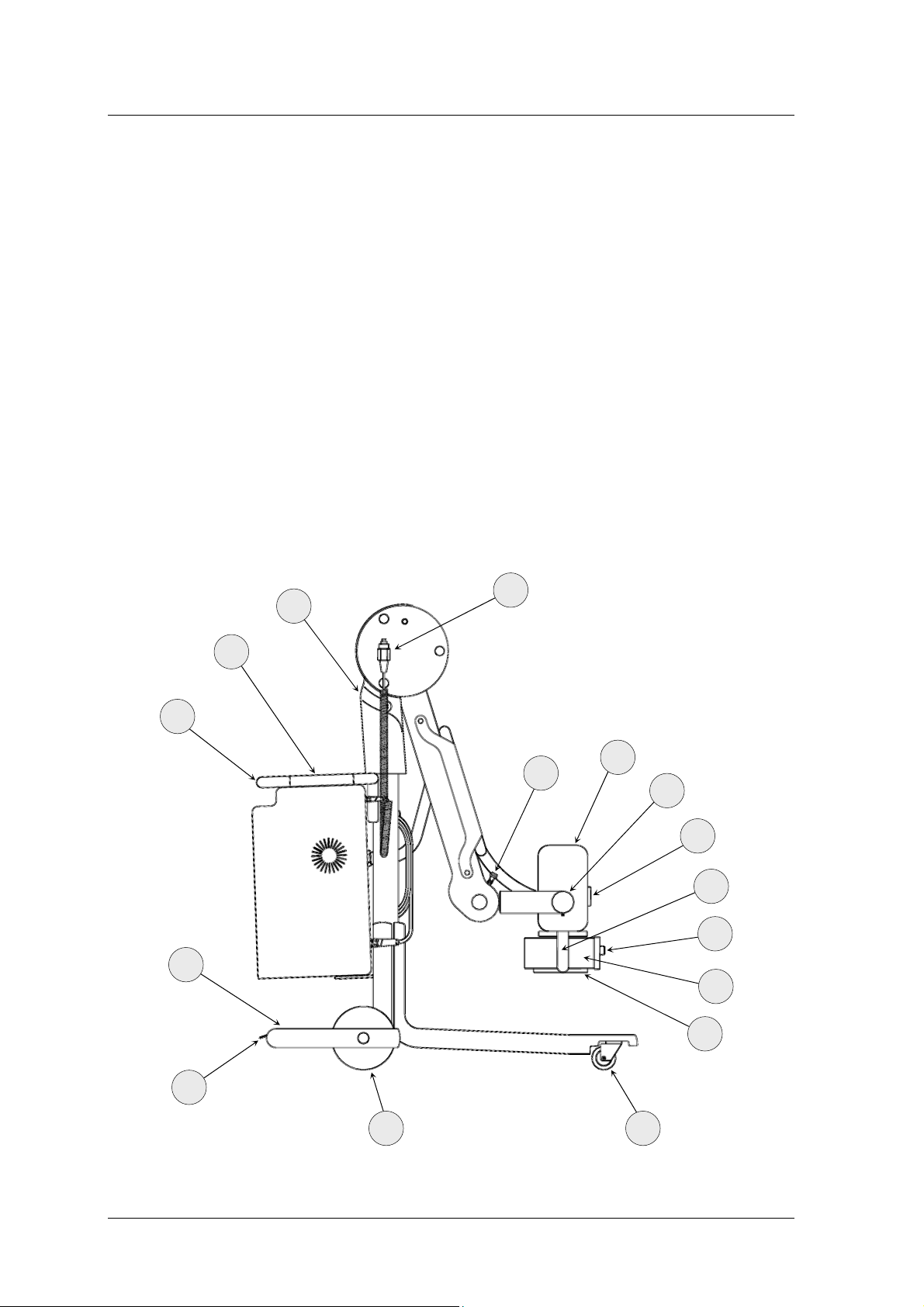
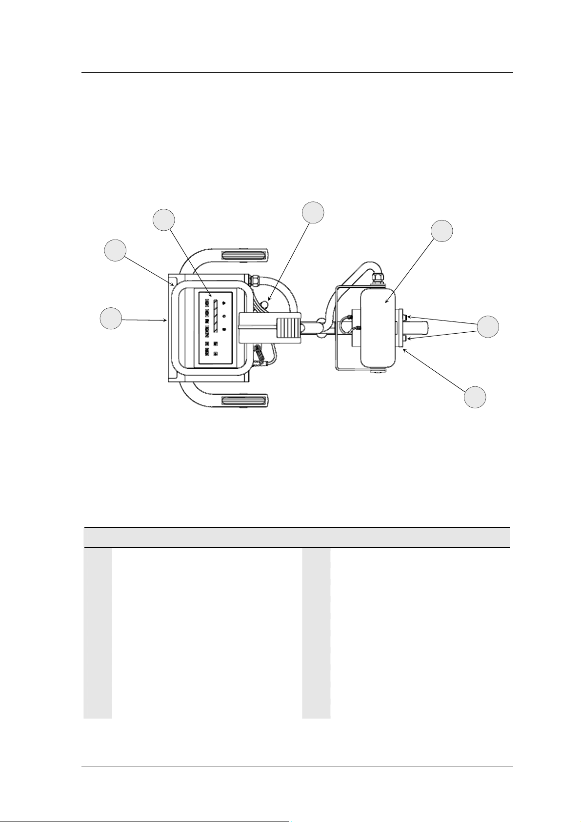
2.1 MOBILE RADIOGRAPHIC UNIT
3
18
2
1
4
15
5
6
7
14
9
8
10
19
Section 1
Page 2 of 14 Doc. 7761
1113
Page 8
Service Manual
GENERAL DESCRIPTION
2
1
16
12
4
9
MOBILE RADIOGRAPHIC UNIT
Transport handle with brake
1
Control panel
2
Handle for tilting (optional)
3
X-ray tube head
4
Lateral goniometer
5
Pivoting wheel (front whell)
11
Power supply cable holder
12
Wheels (main whell)
13
Support for Tilting
14
Pantograph arm lock
15
8
Front goniometer
6
X-ray tube head positioning handle
7
Collimator
8
Adjustment of collimator diaphragms
9
Rail for filters and accessories
10
Doc. 7761 Page 3 of 14
Cassette holder
16
…
X-ray control pushbutton
18
Pedal for Stationary brake
19
Section 1
Page 9
Service Manual
GENERAL DESCRIPTION
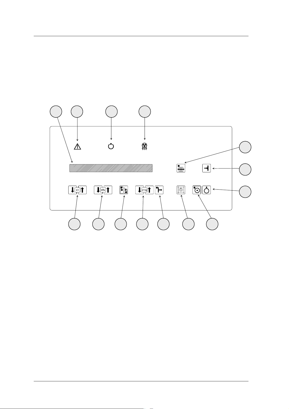
2.2 CONTROL PANEL
13
12 11 14
10
9
8
1 2 3 4 5 6 7
Section 1
Page 4 of 14 Doc. 7761
Page 10
Service Manual
GENERAL DESCRIPTION
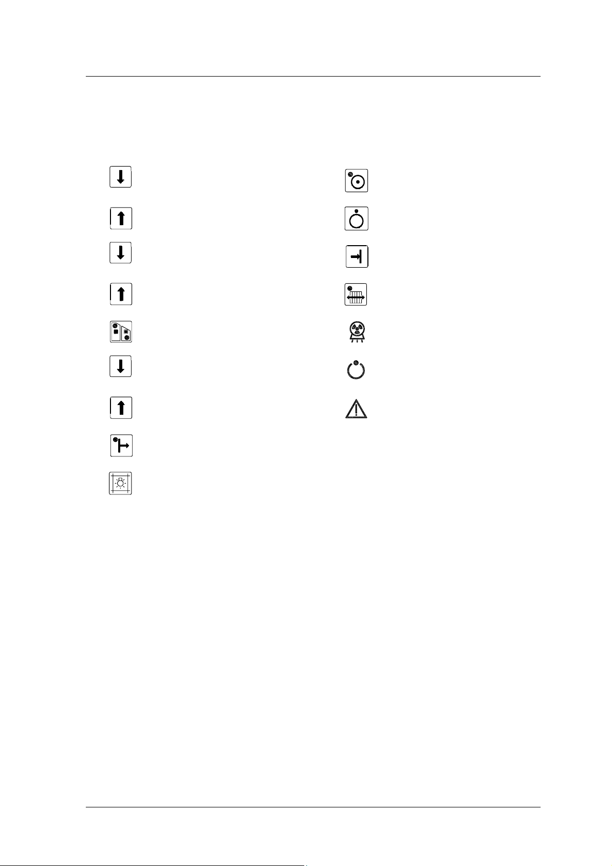
kV decrease
kV
1
kV increase
mAs decrease
mAs
2
mAs increase
3
HP/LP
(1)
Power selection 11
Prog
4
N° of exams memorized in Technique
Anatomical
5
Anatomical Technique Selection 14
7 Unit ON
8 Unit OFF
9
10 Potter-Bucky selection
Data storage in anatomical
technique
X-Ray exposure
12
13 Alarm signalling
X-Ray ready
Display for Dates and Messages
6
Collimator light activation
(1) A change of the Power level involves a change of the used focal spot:
• High Power (HP) – Big Focus
• Low Power (LP) – Small Focus
In the following paragraphs the abbreviations HP and LP will be used.
Section 1
Doc. 7761 Page 5 of 14
Page 11
Service Manual
GENERAL DESCRIPTION
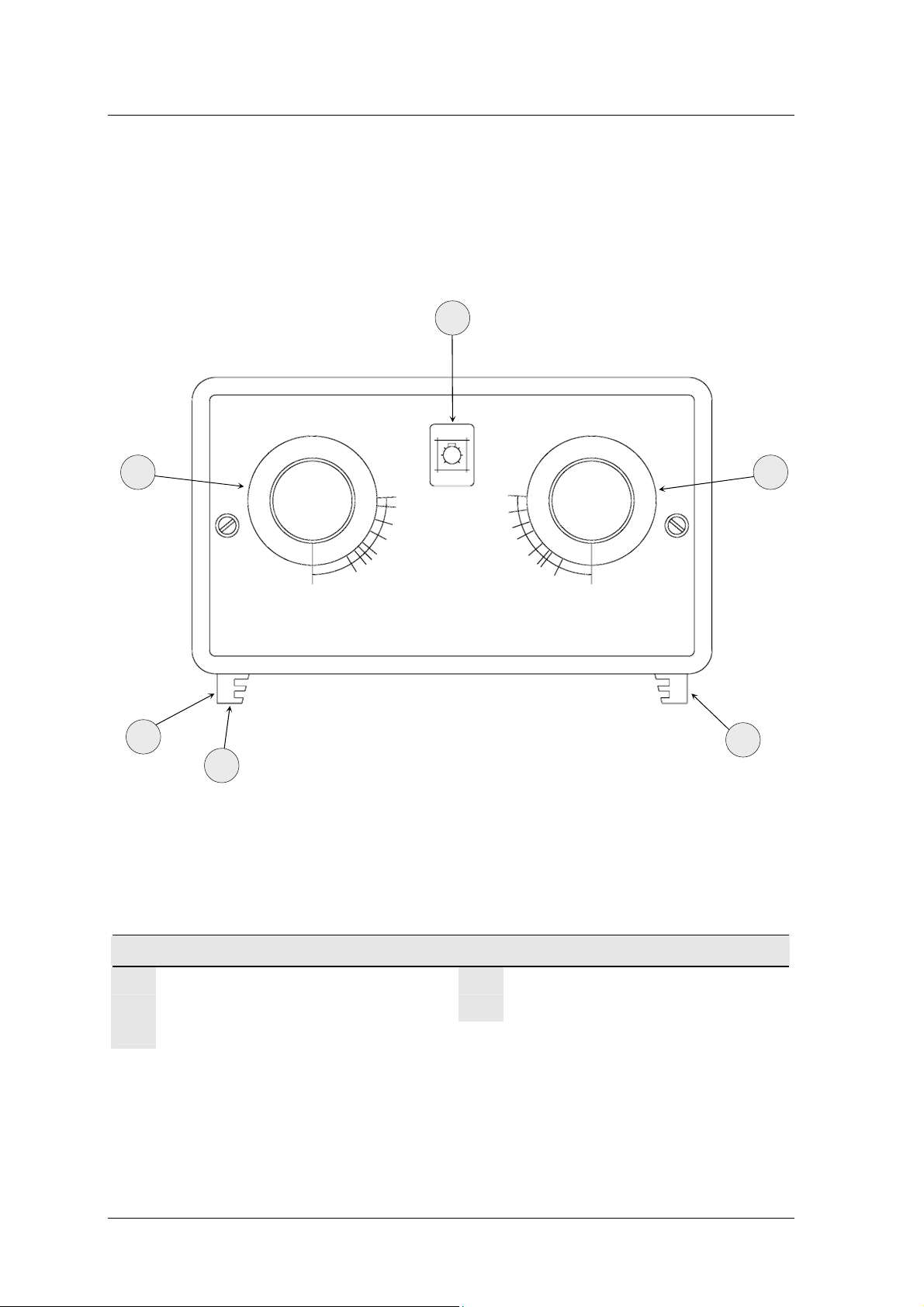
2.3 COLLIMATOR
51
50
54
52
COLLIMATOR
Collimator light on
50
Adjustment of transverse diaphragm
51
53
Retractile meter
53
Adjustment of longitudinal diaphragm
54
52
Rail for filters and accessories
52
Section 1
Page 6 of 14 Doc. 7761
Page 12
3 TECHNICAL DATA
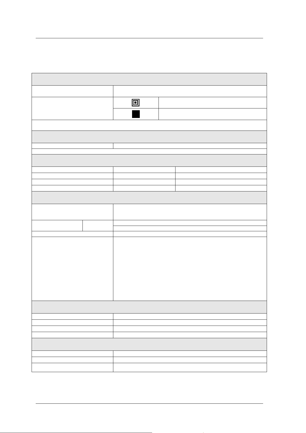
3.1 CLASSIFICATION OF THE APPARATUS
CLASSIFICATION – EN 60601 1 § 5
Service Manual
GENERAL DESCRIPTION
¯ Type of protection against short circuit: C
¯ Degree of protection against direct and indirect contact: T
¯ Use conditions: C
ONTINUOUS WORKING WITH INTERMITTENT LOAD
¯ Unit not to be used in the presence of an inflammable anaesthetic mixture with air or
nitrous oxide
CLASSIFICATION – 93/42/EEC DIRECTIVE
¯ In according with Annex IX: C
3.2 TECHNICAL CHARACTERISTICS
Electrical characteristics
SINGLE PHASE VOLTAGE
FREQUENCY
STAND-BY WORKING
MAX ABSORBED CURRENT
ADIOGRAPHY WORKING 12 A (115 Vac: 23 A)
R
LINE COMPENSATION
LINE RESISTANCE
Radiological characteristics
LASS I
YPE B
LASS II b
230 Vac ± 10%, 16 A (Optional: 115 Vac ± 10%)
50/60 Hz
1 A (115 Vac: 2.5 A)
Automatic
< 2.5 Ω
15 kW 30 kW
MAX POWER
MAX CURRENT IN RADIOGRAPHY
EXPOSURE TIME
WORKING FREQUENCY
RANGE KV
RANGE MAS
A.T. PILOTAGE
RIPPLE
TOTAL FILTRATION
RISING TIME
Doc. 7761 Page 7 of 14
LP (Low Power) HP (High Power) LP (Low Power) HP (High Power)
7.5 kW 15 kW 7.5 kW 30 kW
150 mA 375 mA 150 mA 425 mA
3 ms ÷ 1.3 s 1 ms ÷ 0.6 s 3 ms ÷ 1.3 s 1 ms ÷ 0.5 s
Selected by the processor according to the mAs
100 kHz
40 ÷ 125 (Step of 1 kV)
0.5 ÷ 200 in 25 values
Inverter driven by IGBT
≤ 3% at Max Power
> 2.7 mmAl
≤ 1 ms
Section 1
Page 13
Service Manual
GENERAL DESCRIPTION
X-Ray Tube Head
TYPE OF ANODE
FOCAL SPOTS
All the other information relevant to the X-Ray Tube Head and to the X-Ray Tube can be found in the X-Ray Tube Head
Technical Data Sheet
Rotation with speed 3000 RPM
0.6 mm
1.3 mm
Collimator (optional)
SHUTTERS TO MULTIPLE PLANS Parallels and perpendicular with manual movement
All the other information relevant to the Collimator can be found in the relative Technical Data Sheet
Dosimeter (optional)
MODEL Kermax-plus VacuDap 2000 with printer optional
ACTIVE AREA 146 x 146 mm2 147 x 147 mm2
MINIMAL DOSE RESOLUTION 1 mGycm2 1 mGycm2
MAXIMAL MEASURABLE DOSE 9999.9999 mGycm2 9999.9999 mGycm2
Operating modes and functionality
INTERFACE USER Polycarbonate flat keyboard with alphanumeric LCD display for all the
operative parameters and messages of possible anomalous conditions –
administrated by a microprocessor.
OPERATING MODES RADIOGRAPHY
X-RAY CONTROL Distance control with double – click and extensible cable (≥4m)
SAFETY
Two-points techniques (kV-mAs)
40 programmable anatomic technique (20 for LP and 20 for HP)
Filament current
mA
and mA
min
Maximum exposure time
Temperature maximum X-ray tube head
Count thermal units X-ray tube head
Max kV, min kV, max ∆kV, max I
Anode rotation
Microprocessor self – test
max
Transport and storage conditions
MAXIMAL TEMPERATURE
RECOMMENDED TEMPERATURE
RELATIVE HUMIDITY
ATMOSPHERIC PRESSURE
–10°C ÷ 55°C
0°C ÷ 40°C
20% ÷ 90%
500 hPa ÷ 1060 hPa
Operating conditions
TEMPERATURE
RELATIVE HUMIDITY
ATMOSPHERIC PRESSURE
Section 1
Page 8 of 14 Doc. 7761
10°C ÷ 40°C
30% ÷ 75%
700 hPa ÷ 1060 hPa
Page 14
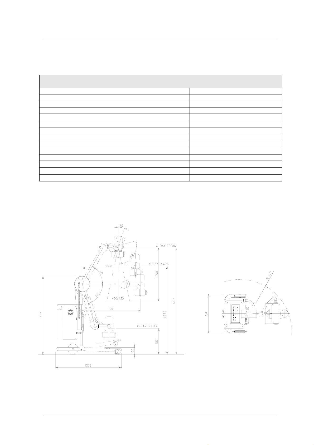
Mechanical Characteristics
Service Manual
GENERAL DESCRIPTION
WIDTH
LENGHT
HEIGHT
MIN SOURCE-FLOOR DISTANCE
MAX SOURCE-FLOOR DISTANCE
MAX RANGE
FOCUS MAXIMUM HEIGHT, WITH RANGE 1000 MM
PIVOTING FRONT WHEEL Ø 75
MAXIMUM DIFFERENCE IN LEVEL WHICH CAN BE OVERCOME WITH TILTING
BACK WHEELS DIAMETER
MINIMUM DEFLECTING RAY
WEIGHT
MOVEMENT
CASSETTE HOLDER 35X43
977 mm
734 mm
1259 mm
1467 mm
489 mm
1997 mm
1091 mm
1656 mm
360°
25 mm
Ø 200
191 kg (115 Vac: 205 kg)
Manual
4
3.2.1 DIMENSIONS AND WEIGTHS
Drawing N°: 7742
Section 1
Doc. 7761 Page 9 of 14
Page 15
Service Manual
-
y
GENERAL DESCRIPTION
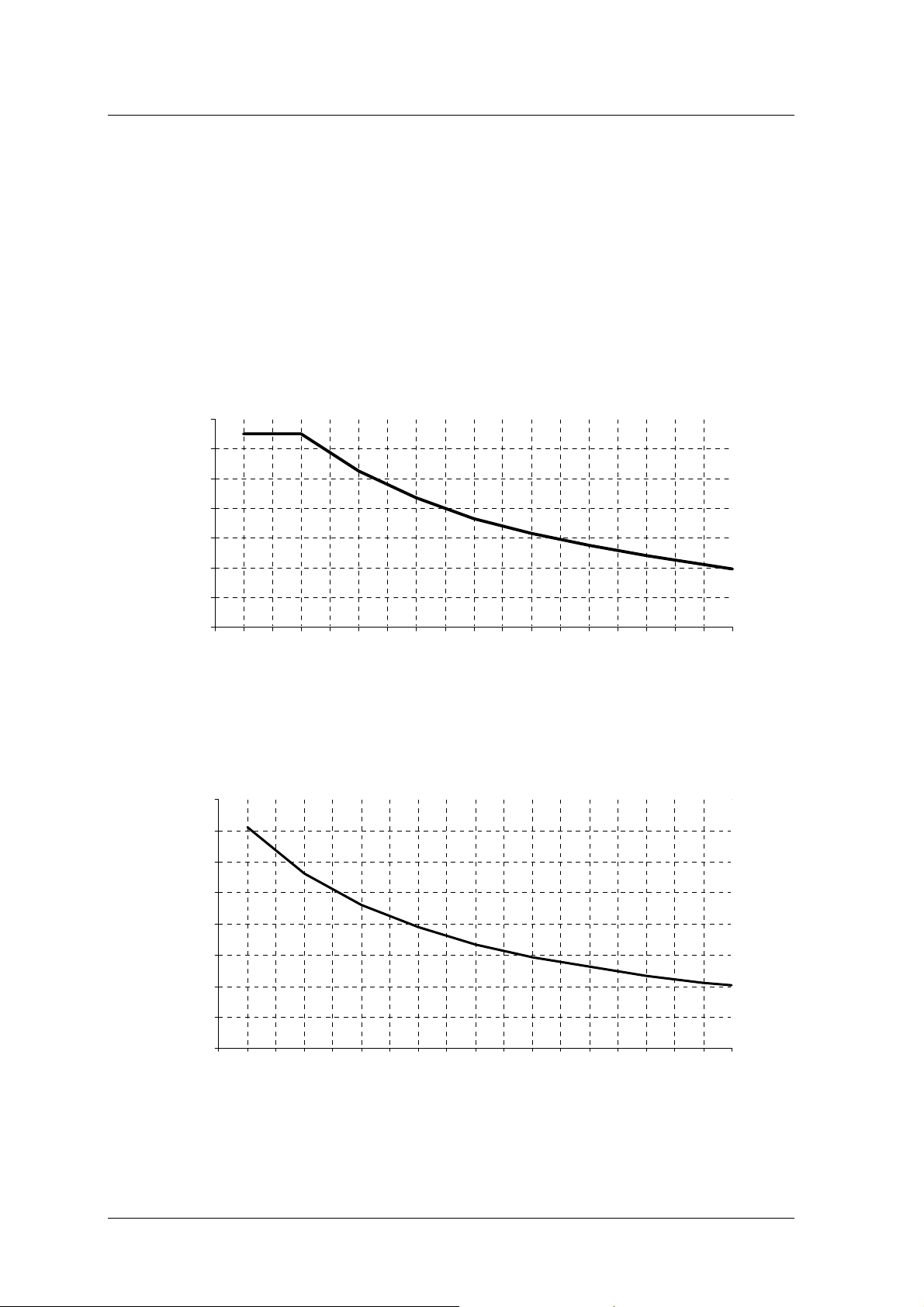
3.2.2 KV – mA RELATIONSHIP
kV - mA Relationship in Radiography mode -
160,00
140,00
120,00
100,00
80,00
60,00
mA Radiography
40,00
20,00
35 40 45 50 55 60 65 70 75 80 85 90 95 100 105 110 115 120 125
kV - mA Relationship in Radiography mode
420,00
370,00
320,00
270,00
220,00
170,00
mA Radiograph
120,00
70,00
20,00
35 40 45 50 55 60 65 70 75 80 85 90 95 100 105 110 115 120 125
7.5kW
kV
15kW
kV
Section 1
Page 10 of 14 Doc. 7761
Page 16
Service Manual
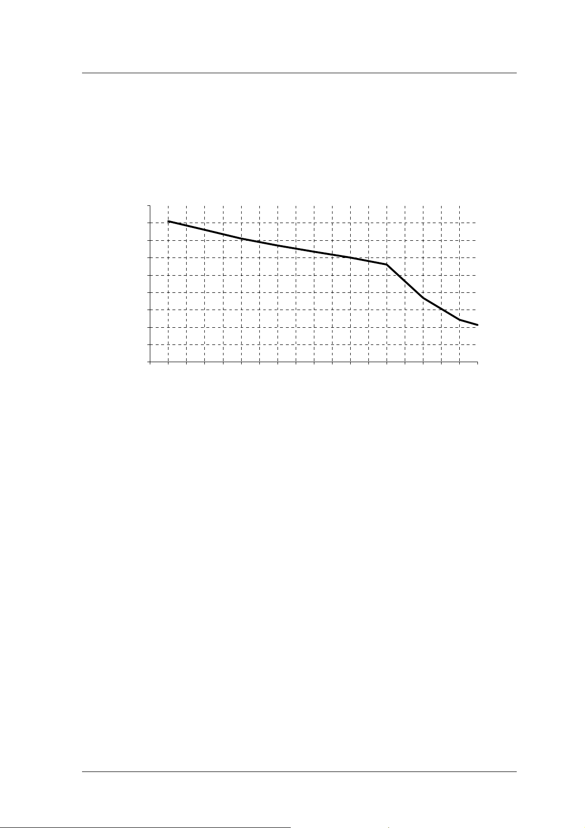
GENERAL DESCRIPTION
470,00
420,00
kV - mA Relationship in Radiography mode -
30kW
370,00
320,00
270,00
220,00
170,00
mA Radiography
120,00
70,00
20,00
35 40 45 50 55 60 65 70 75 80 85 90 95 100 105 110 115 120 125
kV
Section 1
Doc. 7761 Page 11 of 14
Page 17
Service Manual
GENERAL DESCRIPTION
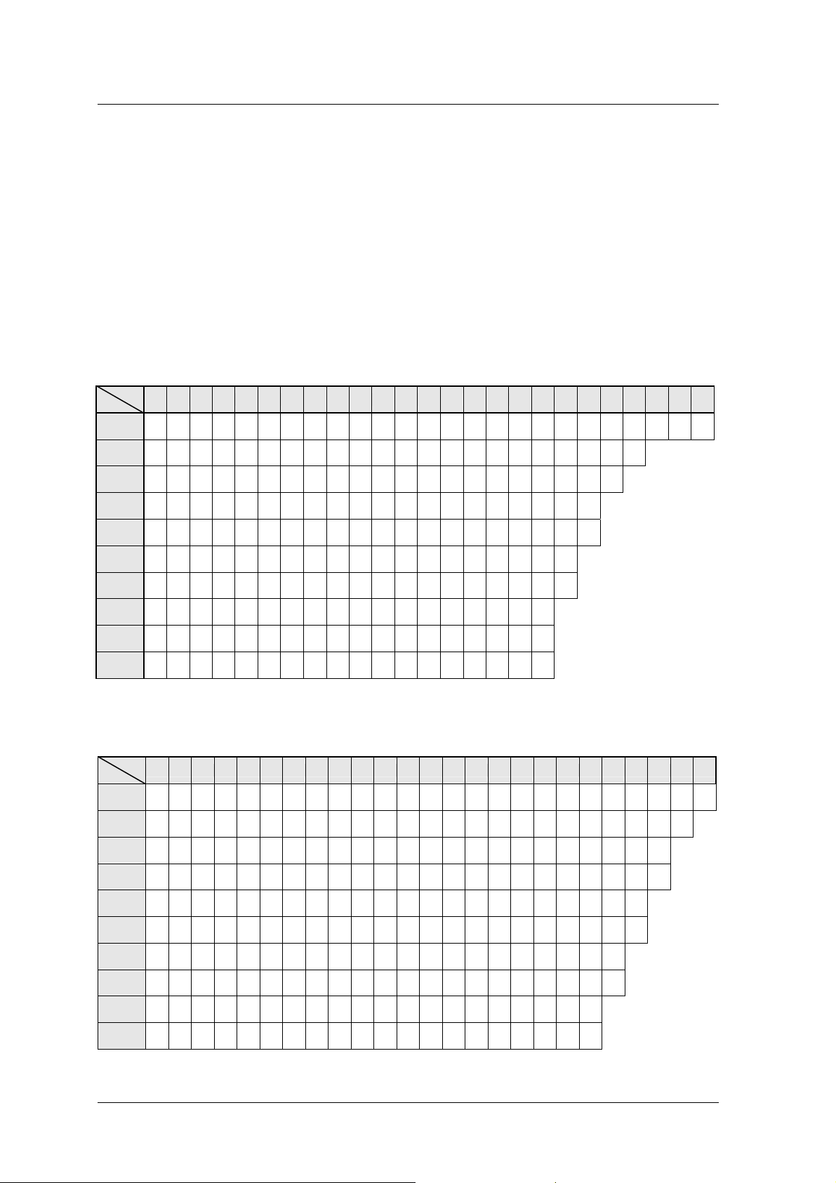
3.2.3 RX EXPOSURE TIME
In the following tables the exposure times (s) associated to kV and mAs are reported. Since
the apparatus is a device functioning with a two point technique (kV and mAs) we remind that the
values indicated in the table are merely theoretical and can undergo a variation in relation to the
tolerance of the mA.
TABLE 1 – 7.5KW POWER
mAs
kV
(150mA)
(150mA)
(125mA)
(107mA)
(93mA)
(83mA)
(75mA)
(68mA)
(62mA)
(59mA)
0,5 1 1,3 1,6 2 2,5 3,2 4 5 6,3 8 10 13 16 20 25 32 40 50 63 80 100 130 160 200
40
0,003 0,006 0,008 0,010 0,013 0,016 0,021 0,026 0,033 0,042 0,053 0,066 0,086 0,106 0,133 0,166 0,213 0,266 0,333 0,420 0,533 0,666 0,866 1,066 1,333
50
0,003 0,006 0,008 0,010 0,013 0,016 0,021 0,026 0,033 0,042 0,053 0,066 0,086 0,106 0,133 0,166 0,213 0,266 0,333 0,420 0,533 0,666
60
0,004 0,008 0,010 0,012 0,016 0,020 0,025 0,032 0,040 0,050 0,064 0,080 0,104 0,128 0,160 0,200 0,256 0,320 0,400 0,504 0,640
70
0,004 0,009 0,012 0,014 0,018 0,023 0,029 0,037 0,046 0,058 0,074 0,093 0,121 0,149 0,186 0,233 0,299 0,373 0,467 0,588
80
0,005 0,010 0,013 0,017 0,021 0,026 0,034 0,043 0,053 0,067 0,086 0,107 0,139 0,172 0,215 0,268 0,344 0,430 0,537 0,677
90
0,006 0,012 0,015 0,019 0,024 0,030 0,038 0,048 0,060 0,075 0,096 0,120 0,156 0,192 0,240 0,301 0,385 0,481 0,602
100
0,006 0,013 0,017 0,021 0,026 0,033 0,042 0,053 0,066 0,084 0,106 0,133 0,173 0,213 0,266 0,333 0,426 0,533 0,666
110
0,007 0,014 0,019 0,023 0,029 0,036 0,047 0,058 0,073 0,092 0,117 0,147 0,191 0,235 0,294 0,367 0,470 0,588
120
0,008 0,016 0,020 0,025 0,032 0,040 0,051 0,064 0,080 0,101 0,129 0,161 0,209 0,258 0,322 0,403 0,516 0,645
125
0,008 0,017 0,022 0,027 0,034 0,042 0,054 0,068 0,085 0,107 0,136 0,169 0,220 0,271 0,339 0,424 0,542 0,678
TABLE 2 – 15KW POWER
mAs
kV
(375mA)
(300mA)
(250mA)
(214mA)
(187mA)
(166mA)
(150mA)
(136mA)
(125mA)
(121mA)
Section 1
Page 12 of 14 Doc. 7761
0,5 1 1,3 1,6 2 2,5 3,2 4 5 6,3 8 10 13 16 20 25 32 40 50 63 80 100 130 160 200
40
0,001 0,002 0,003 0,004 0,005 0,006 0,008 0,010 0,013 0,016 0,021 0,026 0,034 0,042 0,053 0,066 0,085 0,106 0,133 0,168 0,213 0,266 0,346 0,426 0,533
50
0,001 0,003 0,004 0,005 0,006 0,008 0,010 0,013 0,016 0,021 0,026 0,033 0,043 0,053 0,066 0,083 0,106 0,133 0,166 0,210 0,266 0,333 0,433 0,533
60
0,002 0,004 0,005 0,006 0,008 0,010 0,012 0,016 0,020 0,025 0,032 0,040 0,052 0,064 0,080 0,100 0,128 0,160 0,200 0,252 0,320 0,400 0,520
70
0,002 0,004 0,006 0,007 0,009 0,011 0,014 0,018 0,023 0,029 0,037 0,046 0,060 0,074 0,093 0,116 0,149 0,186 0,233 0,294 0,373 0,467 0,607
80
0,002 0,005 0,006 0,008 0,010 0,013 0,017 0,021 0,026 0,033 0,042 0,053 0,069 0,085 0,106 0,133 0,171 0,213 0,267 0,336 0,427 0,534
90
0,003 0,006 0,007 0,009 0,012 0,015 0,019 0,024 0,030 0,037 0,048 0,060 0,078 0,096 0,120 0,150 0,192 0,240 0,301 0,379 0,481 0,602
100
0,003 0,006 0,008 0,010 0,013 0,016 0,021 0,026 0,033 0,042 0,053 0,066 0,086 0,106 0,133 0,166 0,213 0,266 0,333 0,420 0,533
110
0,003 0,007 0,009 0,011 0,014 0,018 0,023 0,029 0,036 0,046 0,058 0,073 0,095 0,117 0,147 0,183 0,235 0,294 0,367 0,463 0,588
120
0,004 0,008 0,010 0,012 0,016 0,020 0,025 0,032 0,040 0,050 0,064 0,080 0,104 0,128 0,160 0,200 0,256 0,320 0,400 0,504
125
0,004 0,008 0,011 0,013 0,016 0,021 0,026 0,033 0,041 0,052 0,066 0,082 0,107 0,132 0,165 0,207 0,264 0,331 0,413 0,521
Page 18
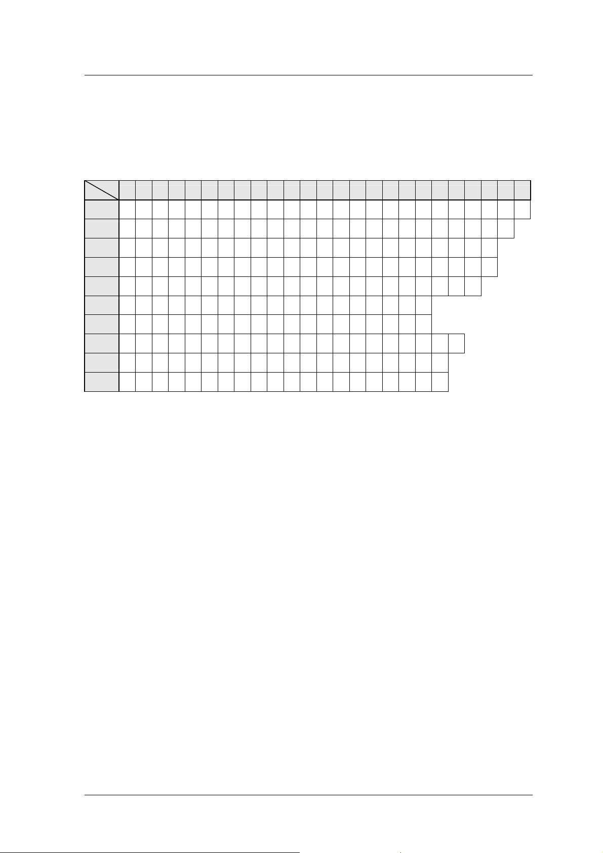
TABLE 3 – 30KW POWER
mAs
kV
(425mA)
(400mA)
(375mA)
(355mA)
(337mA)
(320mA)
(300mA)
(204mA)
(141mA)
(126mA)
0,5 1 1,3 1,6 2 2,5 3,2 4 5 6,3 8 10 13 16 20 25 32 40 50 63 80 100 130 160 200
40
0,001 0,002 0,003 0,003 0,004 0,005 0,007 0,009 0,011 0,014 0,018 0,023 0,030 0,037 0,047 0,058 0,075 0,094 0,117 0,148 0,188 0,235 0,305 0,376 0,470
50
0,001 0,002 0,003 0,004 0,005 0,006 0,008 0,010 0,012 0,015 0,020 0,025 0,032 0,040 0,050 0,062 0,080 0,100 0,125 0,157 0,200 0,250 0,325 0,400
60
0,001 0,002 0,003 0,004 0,005 0,006 0,008 0,010 0,013 0,016 0,021 0,026 0,034 0,042 0,053 0,066 0,085 0,106 0,133 0,168 0,213 0,266 0,346
70
0,001 0,002 0,003 0,004 0,005 0,007 0,009 0,011 0,014 0,017 0,022 0,028 0,036 0,045 0,056 0,070 0,090 0,112 0,140 0,177 0,225 0,281 0,366
80
0,001 0,002 0,003 0,004 0,005 0,007 0,009 0,011 0,014 0,018 0,023 0,029 0,038 0,047 0,059 0,074 0,094 0,118 0,148 0,186 0,237 0,296
90
0,001 0,003 0,004 0,005 0,006 0,007 0,010 0,012 0,015 0,019 0,025 0,031 0,040 0,050 0,062 0,078 0,100 0,125 0,156
100
0,001 0,003 0,004 0,005 0,006 0,008 0,010 0,013 0,016 0,021 0,026 0,033 0,043 0,053 0,066 0,083 0,106 0,133 0,166
110
0,002 0,004 0,006 0,007 0,009 0,012 0,015 0,019 0,024 0,030 0,039 0,049 0,063 0,078 0,098 0,122 0,156 0,196 0,245 0,308 0,392
120
0,003 0,007 0,009 0,011 0,014 0,017 0,022 0,028 0,035 0,044 0,056 0,070 0,092 0,113 0,141 0,177 0,226 0,283 0,354 0,446
125
0,004 0,008 0,010 0,013 0,016 0,020 0,026 0,032 0,040 0,050 0,063 0,079 0,103 0,127 0,159 0,198 0,254 0,317 0,397 0,500
Service Manual
GENERAL DESCRIPTION
Section 1
Doc. 7761 Page 13 of 14
Page 19

Service Manual
GENERAL DESCRIPTION
Section 1
Page 14 of 14 Doc. 7761
Page 20

Service Manual
Installation
Section 2
Doc. 7762 Page 1 of 10
Page 21
Service Manual
INSTALLATION
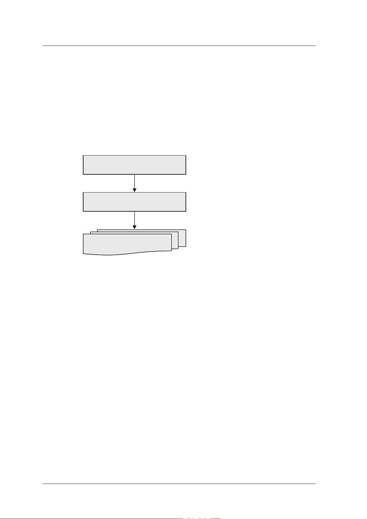
1 INTRODUCTION
The installation procedure consists of different operations to be carried out in the order shown in
the flow chart below.
Unpacking
Electrical connection
Acceptance test
The various operations indicated are described in detail in the following paragraphs.
The installation process can only be considered completed after the T
acceptance tests provided with this manual
has been filled in.
EST SHEET regarding the
N
OTE: the radiological system is normally pre-installed and configured in the factory according to
the specific requirements of the customer. Certain adjustments may, however, be necessary when
components are replaced.
The whole machine parameter adjustment procedure is described in detail in this manual (SECTION
4).
Section 2
Page 2 of 10 Doc. 7762
Page 22

Service Manual
INSTALLATION
2 UNPACKING
The radiological system is packed in a single case containing all the parts of the apparatus. To
unpack the unit, proceed as described on the following page, according to the type of packing:
¯ simple pallet with cellophane – SEE § 2.1
¯ pallet with carton – S
¯ wood packing crate – S
EE § 2.2
EE § 2.3
If necessary, follow the unpacking procedure backwards to pack the unit again.
2.1 PACKING WITH CELLOPHANE
1. Cut the tape (4) and remove the slide (5) – SEE FIGURE 1
2. remove the protective bag (6)
3. unscrew the four self-threading screws (7) which fix the anterior wheel fixing bracket (8)
4. free the X-ray Tube Head fixing brackets (9) from the tie-rod (14) - S
working on nuts (10)
5. unscrew the self-threading screws (11) and remove the X-ray Tube Head fixing brackets
EE FIGURE 2 -
(9)
6. put the slide (5) on the floor, as shown in F
IGURE 1
7. unscrew the screws (12) which fix the stand to the packing bracket (13)
8. slowly move the mobile unit towards the slide (5), paying attention to the packing
bracket (13)
9. let the unit move slowly from the slide (5) till its complete positioning on the floor.
Section 2
Doc. 7762 Page 3 of 10
Page 23

Service Manual
INSTALLATION
Packing position
5
6
10
4
12
9
8
13
11
7
5
Floor position
FIGURE 1 - LATERAL VIEW
11
10
FIGURE 2 - VIEW FROM ABOVE
14
Section 2
Page 4 of 10 Doc. 7762
Page 24

Service Manual
INSTALLATION
2.2 PACKING WITH CARTON
1. Remove the screws (1) - SEE FIGURE 3 - which fix the packing carton to the crate pallet
(2)
2. cut the band (3)
3. remove the carton packing from its housing; the
mobile unit is as shown in FIGURE 1
4. proceed according to the packing with cellophane procedure (§ 2.1).
3
2
1
FIGURE 3 - PALLET WITH CARTON
Section 2
Doc. 7762 Page 5 of 10
Page 25

Service Manual
INSTALLATION
2.3 PACKING WITH WOOD CRATE
1. Dismantle the crate cover (1) – SEE FIGURE 4
2. remove the crate walls: be careful not to ruin the wall (5) that has to be used as slide; the
mobile unit is as shown in F
IGURE 1
Note: in the wood packing case, the slide (5) is not mounted as shown in F
because it is substituted by the wall (5), previously mentioned
3. proceed according to the packing with cellophane procedure (§ 2.1).
1
IGURE 1,
5
FIGURE 4 - WOOD CRATE
Section 2
Page 6 of 10 Doc. 7762
Page 26

Service Manual
INSTALLATION
3 ELECTRICAL CONNECTIONS
The power supply single-phase alternate voltage and maximum absorbed current values are
reported both on the unit label and on the technical data (S
Make sure that the power supply socket is approved for the values reported on
!
the unit label
EE SECTION 1 - § 3.2).
4 ACCEPTANCE TEST
The ACCEPTANCE TEST includes all the control and checking operations listed on the TEST
. These operations must be grouped together under three general categories:
SHEET
¯ checking cables and connectors
¯ mechanical checks
¯ electrical checks
Each operation is identified by a code which is then used on the T
EST SHEET.
4.1 CHECKING CABLES AND CONNECTORS
Visually control each cable and each connector, checking that there are no interruptions and/or
crushing.
A.1 Power supply cable of the unit
A.2 Radiography control pushbutton cable
A.3 Connection cable between unit/X-ray tube head
Doc. 7762 Page 7 of 10
Section 2
Page 27

Service Manual
INSTALLATION
4.2 MECHANICAL CHECKS
The mechanical checks include the following operations:
¯ MOVEMENTS: all the movements foreseen must be possible without excessive force or
jerks
RAKES all the movement locking brakes must be operating and easily applied
¯ B
OUNDNESS: check that there are no breakages and/or damage which might have
¯ S
jeopardised operation and safety of the apparatus.
The single checking phases are listed below.
B.1 Unit sliding movement
B.2 Unit parking brake
B.3 Proper Functioning of the antitilting assemblies
B.4 Integrity of the Control panel
B.5 Integrity and fixing of the carters
B.6 Balance of the pantograph arm.
4.3 ELECTRICAL CHECKS
With regard to the electrical part, correct operation of the following must be checked:
¯ S
AFETY DEVICES
IGNALS
¯ S
NOTE: Remove the carters to carry out the electrical checks.
The procedure is described below:
C.1 P
C.2 I
OWER SUPPLY: connect the unit to the mains power supply;
NITIAL TEST: check that the initial automatic test is correct of the unit;
C.3 S
C.4 L
OFTWARE: check that the visualization of installed software;
OADING: check that the switching on the unit appears the increment of voltage on
display until 350 V. The complete loading of the capacitors battery is ready in about
40/45 sec;
Section 2
Page 8 of 10 Doc. 7762
Page 28

Service Manual
C.5 DISCHARGING: switch the unit off and check the complete discharging of the
capacitors battery by means the switching off the LD3 led mounted on S25 board;
INSTALLATION
!
C.6
C.7 X-
Do not carry out switching the unit On and Off
SET-UP DATES IN MEMORY: enter on SET-UP (SEE SECTION 4 - § 3) and check that the
ET-UP dates are in according with dates selected (SEE SECTION 4 - § 3 – TAB. 2);
S
RAY TUBE FORMATION: when not in used the unit for a long time, before to use the
unit normally, carry out the “formation” of the X-ray tube with a serial of exposure
using the following dates (carry out for each value of kV and mAs 10 exposure and
keep a pause of 1 minute between an exposure and another one):
40 kV 100 mAs
50 kV 80 mAs
60 kV 64 mAs
70 kV 64 mAs
80 kV 50 mAs
90 kV 50 mAs
100 kV 40 mAs
110 kV 40 mAs
120 kV 40 mAs
During this formation check with oscilloscope the value of kV [S19/B board Tp11 (-);
Tp3 (+) ] and mA [S19/B board: Tp11 (-); Tp6 (+) ] on inverter. Select the
oscilloscope in the following way:
HANNEL A: 1 V/DIV ( 1V read is equal to 50 mA)
C
HANNEL B: 1 V/DIV ( 1V read is equal to 20 KV)
C
B
ASE TIME: 25ms/DIV
Section 2
Doc. 7762 Page 9 of 10
Page 29

Service Manual
INSTALLATION
In case of kV wave form presents of high voltage discharge or you hear discharge
inside X-ray tube interrupt the sequence, wait few minutes before starting again;
repeat the initial formation checking that the fuse F7 is interrupted (100A) (S
EE
ELECTRICAL DRAW);
!
Warning: presence of 350 Vdc voltage!
C.8 E
XPOSURE TIME: check that during exposure time the X-ray passage led until the end
of exposure the display shows the real exposure time in second (S
EE SECTION 1 - §
3.2.3).
Section 2
Page 10 of 10 Doc. 7762
Page 30

Service Manual
Maintenance
Section 3
Doc. 7763 Page 1 of 10
Page 31

Service Manual
MAINTENANCE
1 ROUTINE MAINTENANCE
1.1 GENERAL RECOMMENDATIONS
The radiological system requires regular checks and maintenance. The following
recommendations have the aim of helping the operator to keep the apparatus in good working and
safe conditions during service.
The system contains mechanical parts subject to wear according to use: following prolonged
use, wear on parts may decrease safety during use. For this reason, it is essential for the checking
and maintenance operations indicated below to be carried out consistently to protect the operators
and patients against any damage caused by mechanical breakdowns.
Correct adjustment of the electrical and electronic systems has a direct influence on the
operation of the system, on the quality of the image and on the electrical safety of the system, as
well as on the level of exposure to radiation the operators and patients are subjected to.
The M
and interventions to be carried out by specialised personnel authorised by the manufacturer. All
maintenance operations are the responsibility of the owner of the apparatus.
AINTENANCE PROGRAMME, described in the following paragraphs, consists of controls
Should it be necessary to replace components or parts which may in any way
!
condition the safety of the machine, only use original spare parts.
Section 3
Page 2 of 10 Doc. 7763
Page 32

Service Manual
MAINTENANCE
1.2 FREQUENT CHECKS AND INSPECTIONS
The operating personnel must be suitably trained to be able to carry out the daily and weekly
checks indicated in T
ABLE 1.
The other controls described in this chapter and the interventions described in the following
chapters are reserved for qualified and authorised personnel of the technical assistance service.
T
ABLE 1
INTERVAL CHECK
DAILY
CHECKS
WEEKLY
CHECKS
6-MONTHLY
CHECKS
Operation of the signals, displays and LEDs
Operation of the stationary brake
Integrity of the warning and danger labels
Absence of oil leaks from the X-ray tube head
Absence of unusual noises in the X-ray tube head during X-ray emission
Correct operation and the value of the whole earthing circuit
Power supply voltage value
Value of the continuous voltages generated inside the system
Fixing and general state (dust and corrosion) of the boards
Centering of the X-ray tube head-collimator assembly
1.3 GENERAL CHECKS AND INSPECTIONS
Every six months, and in any case according to local legislation in force, the procedures
indicated in the A
are noted down on the T
CCEPTANCE TEST REPORT must be carried out completely. The results obtained
EST SHEET together with the description of any interventions carried out.
The checks listed below must be added to those contained on the Test Sheet:
D.1 Power supply voltage check
D.2 DC power supply check
D.3 Protection earth check
D.4 Internal earth connection check
Section 3
Doc. 7763 Page 3 of 10
Page 33

Service Manual
MAINTENANCE
1.4 CLEANING AND DISINFECTION
Products with a high content of alcohol, corrosive and/or abrasive detergents or solvents must
not be used to clean the surfaces of the apparatus.
To disinfect the system, only use methods in compliance with the laws in force regarding
disinfection and protection procedures against explosion.
To carry out the cleaning and disinfection operations, take the following precautions:
turn the system off and disconnect the mains power supply cable
make sure that no liquid gets into the apparatus so as to avoid any short-circuits or
corrosion of the electrical and electromechanical parts.
The unit has not to be used in presence of anaesthetic and/or infiammable
disinfectant and cleaning products.
!
If, producing explosive gaseous, mixture, are used, make sure that gases are
dispersed before switching on the unit.
Section 3
Page 4 of 10 Doc. 7763
Page 34

Service Manual
MAINTENANCE
2 SPECIAL MAINTENANCE
2.1 TROUBLESHOOTING
Troubleshooting can be facilitated by the indications given in TABLE 2, which illustrates the
most common incorrect operating conditions, showing their probable causes. In the presence of the
following alarms visualized on the display, the X-ray exposition is disqualified and the console’s
alarm red led light up. In case it is also present after the execution of the suggested intervention,
please contact the service assistance department.
TABLE 2
N° FAULT NOTED LIKELY CAUSE RECOMMENDED INTERVENTION
The unit doesn’t switch on (on key LED
1
switched on)
The unit doesn’t switch on (on key LED
switched off)
The apparatus works but does not emit
2
rays – No alarm on the unit display
Alarm: “SUPPLY FAULT” +15V or –15V fault of the S22
3
Alarm: “FILAMENT FAULT”
4
Alarm: “INVERTER FAULT”
5
Alarm: “KV FAULT” During a radiograph the effective
6
Alarm: “mA FAULT” During an exposure the mA value
7
Alarm: “THERMIC SAFETY”
8
Alarm: “
9
Alarm: “X-
10
MAN STOP RX” During a radiograph with cassette,
RAY LACKING” Error in the high voltage generation
No power supply on input Check / Replace the S22-F2 or TR2-
F24V fuse
No power supply on input Check / Replace the S22-F1 or F1
fuse (on input)
Radiography pushbutton fault Check the Radiography pushbutton
board supply
400 Hz power supply absent Check / Replace TR2-F130V0 fuse
X-ray tube filament interrupted Replace the X-ray tube head
S15 board fault Replace the board
If the indication appears on standby: P1 Set-Up on S22 board faulty
If the indication appears while
carrying out X-ray: faulty on X-ray
power circuit
F2 and F3 fuses blown Replace F2 and F3 fuses
F6 and F7 fuses blown on the
Power circuit
kV are less than 85% of those set:
fault on the power circuit
is lower than the allowed limit
X-ray tube head overheated Do not carry out any X-rays and wait
Breakage of the thermal sensor Replace the thermal sensor located on
the control pushbutton for X-ray
command has been released early
circuit
cable and connector
Check power supply (+15VA/15VA/+24VA voltage on S22
voltage)
Carry out set-up as in Section 4 - §
4.2
Switching the unit off, switching it on
and repeat the X-ray
Replace F6 and F7 fuses
Switching the unit off, switching it on
and repeat the X-ray
Switching the unit off, switching it on
and repeat the X-ray
for the X-ray tube head to cool down
the X-ray tube head and/or check the
relevant wiring on S22 board
Repeat the radiography
Switching the unit off, switching it on
and repeat exposure
Section 3
Doc. 7763 Page 5 of 10
Page 35

Service Manual
MAINTENANCE
N° FAULT NOTED LIKELY CAUSE RECOMMENDED INTERVENTION
Alarm: “MAX TIME” The radiography time has exceeded
11
the concurred limit
Alarm: “STARTER FAULT”
12
Alarm: “SWITCH OFF FOR 1 MIN” Capacitors bank still loads With the unit off wait 1 minute before
13
Alarm: “BATTERY FAULT” Power Circuit Fault Contact technical service
14
Alarm: “O
15
16
Alarm: “X-RAY COMMAND ACTIVE”
17
Alarm: “X-RAY TUBE TOO HOT”
18
Alarm: “WAIT CONNECTION”
19
Alarm: “POTTER FAULT”
(only with Potter installed)
VERVOLTAGE BATTERY” Battery Circuit Fault Contact technical service
During anode preparation it was
not put into rotation
Fault on board S21/A
Fault on board S20
The operator has pressed the
radiography command before the
system had finished the initial
control stage
It is not possible to begin exposure
since the remaining thermal units
available are too few
The keyboard does not
communicate with the unit
Potter Fault Check the F4 - F5 fuses of the Potter
Check that the mA are correct
Check the mA reading on board S22Tp1 or S19/B-Tp6
Check the fuses on board S21A
Check the stator winding of the X-ray
tube head
Replace board S21/A
Replace board S20
switching it on
Release the radiography pushbutton
and wait until the system is ready
Wait for the X-ray tube to cool down.
Switching the unit off, switching it on
and repeat exposure
power supply and the K3 relè
2.2 REPLACEMENT OF COMPONENTS
Replacement of a component can mean the need to carry out checks and adjustments in order to
reset correct operation of the radiological unit. T
adjustment is necessary.
TABLE 3
COMPONENT REPLACED ADJUSTMENT AND CHECKS REFERENCE
15 BOARD Verify mA set up in SET UP SECTION 4 - § 5
S19/B BOARD Check of kV e mA SECTION 4 - § 5.1 and 8
S20 BOARD
S25 BOARD Check max voltage of battery SECTION 4 - § 7
S28 BOARD Check LCD Display contrast (P1)
Check Run voltage
Check start 800 ms
Check max Set kV (P1) SECTION 4 - § 4.3 S22 BOARD
Check max exposure time (P2) SECTION 4 - § 4.1 and 4.2
ABLE 3 shows typical situations where an
SECTION 4 - § 2
Section 3
Page 6 of 10 Doc. 7763
Page 36

Service Manual
MAINTENANCE
Before effecting the monoblock replacement make the following operations:
for safety purposes add some counterweight on the front part of the unit in order
to avoid the possible tilting of the same.
!
fasten the pantograph arm to the base of the unit (using some ropes) to avoid the
arm making not required movements, due to the loss of weight when the X-ray
tube head is removed.
Consult in any case Mechanical Assembly and Dismantling of the present section.
2.3 LIST POTENTIOMETERS
BOARD POTENTIOMETER VALUE NAME NOTE
S15
S17
S19/B
S25 P1 5K MAX V CAPACITORS BANK Only factory adjustment
S28 P1 20K LCD CONTRAST Only factory adjustment
P1 5K MANUAL SET I FIL (ONLY FOR TEST) Only factory adjustment
P2 5K MAX I FG Only factory adjustment
P3 5K M
P1 10K Only factory adjustment
P2 10K
P3 10K Only factory adjustment
P4 10K
P1 2K MAX CURRENT Only factory adjustment
P2 2K FREQUENCY SET Only factory adjustment
P3 2K MA FLUORO OFFSET ADJ. N.U.
R66 F
P1 1K RUN VOLTAGE Only factory adjustment S20
P2 1M S
P1 2K MAX SET KV Only factory adjustment S22
P2 100K M
AX I FP Only factory adjustment
FEEDBACK KV+
Only factory adjustment
FEEDBACK KV-
Only factory adjustment
EEDBACK MA ADJ Only factory adjustment
TART 800MS Only factory adjustment
AX TIME RAD Only factory adjustment
Section 3
Doc. 7763 Page 7 of 10
Page 37

Service Manual
MAINTENANCE
2.4 LIST LEDS
BOARD LED COLOR NAME NOTE
S15
S19/B
S20
S22
LD1 YELLOW +24V
LD2 GREEN +15VA
LD3 R
LD1 YELLOW COM-RX
LD2 RED ∆ KV MAX
LD3 RED KV > 110%
LD4 RED KV MIN
LD5 RED I MAX
LD6 YELLOW COM. 1
LD7 YELLOW COM. 2
LD8 YELLOW PRE-RX
LD9 GREEN +15V
LD10 G
LD1 YELLOW STARTER ON
LD2 GREEN STARTER OK
LD3 Y
DL1 YELLOW N.U.
DL2 YELLOW N.U.
DL3 YELLOW N.U.
DL4 YELLOW N.U.
DL5 YELLOW N.U.
DL6 YELLOW N.U.
DL7 YELLOW N.U.
DL8 YELLOW N.U.
DL9 YELLOW STARTER OK
DL10 YELLOW PREP K1A
DL11 YELLOW RAD
DL12 YELLOW KV 85%
DL13 YELLOW POTTER OK
DL14 GREEN THERMIC
DL15 YELLOW KV OK
DL16 GREEN FIL OK
DL17 YELLOW PRE RX
DL18 YELLOW RX
DL19 YELLOW PREP K1A
DL20 YELLOW START POTTER
DL21 GREEN +24VA
DL22 GREEN +24VA
DL23 YELLOW ON/OFF
DL25 GREEN +24VA
DL26 YELLOW CAPACITORS BANK CHANGE
DL27 YELLOW CAPACITORS BANK CHARGE
DL28 YELLOW OUT_WD
DL29 YELLOW PREP STARTER
DL30 YELLOW FP
DL31 YELLOW CORR MA
ED SAFETY MAX I FIL
REEN -15V
ELLOW FLUORO PREP (N.U.)
Section 3
Page 8 of 10 Doc. 7763
Page 38

Service Manual
MAINTENANCE
2.5 LIST FUSES
BOARD NAME TYPE NOTE
F2 16A LOADING BATTERY
F3 16A
F6 63A INVERTER
F7 63A
TR1 TRANSFORMER F1 200MA-T Protection TR1 Transformer
TR2 TRANSFORMER
AUTOTRANSFORMER F10 2A-T Protection 115Vac power supply (Optional)
S21/A
S25 F1 80mA-T Input power supply protection S25 Board
S29
F230V 2A-T
F115V 3.15A-T
F135V 1A-T
F24V 2A-T
F12V 10A-T
F4V 2A-T POTTER BUCKY
F5V 2A-T
F1 10A-T
F2 10A-T
F3 500
F1 1A-T S22
2A-T
F2
F1 200mA-T
F2 200mA-T
F3 200mA-T
F4 200mA-T
F5 200mA-T
F6 200mA-T
F7 200mA-T
F8 200mA-T
315mA-T Input power supply protection S29 Board
F9
MA-T Protection TR1 Transformer S21/A Board
Input power supply protection
Protection Inverter
Protection TR2 Transformer
Protection Potter Bucky (Optional)
Input power supply protection S21/A Board
Protection Bridge Rectifier (24Vac)
Protection Bridge Rectifier Group 1 (24Vac)
Protection Bridge Rectifier Group 2 (24Vac)
Protection Bridge Rectifier Group 3 (24Vac)
Protection Bridge Rectifier Group 4 (24Vac)
Section 3
Doc. 7763 Page 9 of 10
Page 39

Service Manual
MAINTENANCE
3 SPARE PARTS
In case of replacing of parts that can be negative for the safety of the machine, use only original
parts. For the list of the spare parts and relative codes to make reference to the S
XPLODED DRAWINGS.
E
ECTION 5 –
N
OTE: When you require spare parts ,it is necessary to tell the code of the piece and the serial
number of the unit too.
Section 3
Page 10 of 10 Doc. 7763
Page 40

Service Manual
X-ray settings
Section 4
Doc. 7764 Page 1 of 18
Page 41

Service Manual
X-RAY SETTINGS
1 INTRODUCTION
The radiological system is fully regulated in the factory: it is therefore only necessary to install it in
order to use it.
All the information contained in this section and S
ECTION 3 of this manual must be used when
extraordinary maintenance is necessary.
In the case of any intervention, it is essential for the adjustment operations to be
!
carried out in the sequence indicated.
ABLE 1 indicates the potentiometers which do not require any further
In T
!
adjustments since they have already been regulated and sealed in the factory.
TABLE 1
BOARD POTENTIOMETER DESCRIPTION
S15
S17 (X-ray tube head)
S25 P1 Maximum battery voltage
P1 Manual Setting of the filament current
P2 Maximum current of large focus
P3 Maximum current of small focus
P1
P2
P3
P4
P1 Maximum current S19/B
P2 Frequency setting
P1 Maximum kV setting S22
P2 Maximum exposure time
Return of the kV+
Return of the kV-
OTE : Jumper S19/B-J2A and J2B ON: safety kV
N
Jumper
S19/B-J2A and J2B OFF: safety kV
set up for rotating anode
max
set up for stationary anode
max
Section 4
Page 2 of 18 Doc. 7764
Page 42

Service Manual
f
X-RAY SETTINGS
1.1 DIP SWITCH
Here follows the function of the dip-switch S22-SW1 pins:
1 – Only factory adjustment 6 – Only factory adjustment
2 – Only factory adjustment 7 – Only factory adjustment
3 – ON – It doesn’t display the name when switched on 8 – Only factory adjustment
4 – Only factory adjustment
5 – ON – Small Focus when switched on
2 ROTATING ANODE STATOR POWER SUPPLY
ADJUSTMENT
Connect an AC voltmeter (true RMS if possible) with full-scale set
at 300 V between the TB3-2 and TB3-3 test points of board S21/A
(power supply of the main winding);
connect the probe of an oscilloscope between IC2-8 (+) and Dz1
Anode (-) of board S20 and prepare the instrument to read a time
of 800 ms;
take the Radiography Command pushbutton.
For maximum operator safety, at this point it is advisable to temporarily disable
!
the X-ray command signal by disconnecting the wire coming from S22-X4-3.
only press the first click of the Radiography Command
pushbutton (preparation pushbutton);
check that the stator is supplied with a voltage of about 230 Vac
for approximately 0,8 seconds. If necessary, adjust this time
s: 300V
TB3-2 TB3-3
interval using potentiometer P2 of board S20;
check that once the 0,8 seconds have passed the stator is supplied
with a voltage of about 70 Vac. If necessary, adjust this value by
using poten-tiometer P1 of board S20.
Section 4
Doc. 7764 Page 3 of 18
Page 43

Service Manual
X-RAY SETTINGS
3 SET-UP PROCEDURE
To access the modality of SET-UP procedure to follow what underneath reported:
press the keys of the console indicated to side at the same time
the wording "SET-UP PROCEDURE ?" will appear on the display;
to confirm selection, press the key indicated at the side marked
with "YES", whereas to cancel the procedure, press the key
marked "NO".
N
OTE: In the Set-up procedure, the functions for editing the content of the fields shown on the
display have been assigned to the keys as indicated below.
YES
+
kV
NO
mAs
-
YES
NO
TABLE 2 – MINIMUM, MAXIMUM AND OF DEFAULT VALUES OF SET-UP ADJUSTMENT
FUNCTION VALUE
DIRECTORY FILE MINIMUM MAXIMUM DEFAULT
kV ADJUSTMENT
SMALL FIL. ADJ 7.5 kW
15 kW
LARGE FIL. ADJ
30 kW
MAS ADJ
BATTERY V = 350
Section 4
Page 4 of 18 Doc. 7764
KV40 300 600 380
kV120 1000 1500 1190
150 mA (40 kV)
75 mA (100 kV)
375 mA (40 kV) 1000 2000 1690
150 mA (100 kV)
425 mA (40 kV)
300 mA (100 kV)
kV 050 (50 mAs)
1000 2000 1600
900 2000 1360
900 2000 1450
1000 2000 1750
900 2000 1560
250 1000 530
Page 44

Service Manual
X-RAY SETTINGS
3.1 SERVICE MENU
When the unit is off, pushing both the keys underneath you enter the SERVICE MENU of the unit
which subsequently visualizes the following data:
name of the device and software version
chosen anatomical program
X-ray tube model
total number of radiographic exposures
total mAs accumulated.
kV
mAs
Section 4
Doc. 7764 Page 5 of 18
Page 45

Service Manual
X-RAY SETTINGS
4 KV ADJUSTMENT
4.1 ADJUSTMENT “SET-UP” VOLTAGE
The SET KV voltage is supplied by the microcomputer and must be adjusted according to the
relationship kV/20 (i.e.: 1V = 20kV).
First of all, enter the S
ET-UP procedure, following the instructions
indicated in the previous paragraph;
On board S19/B connect the probes of a Vdc digital multimeter
between CP1-10 (+) and TP11 (-);
in Set-up select "kV ADJ at 40 kV";
adjust the value until a reading of 2,00 V is obtained on the
voltmeter;
in S
ET-UP select "kV ADJ at 120 kV";
adjust the value until a reading of 6,00 V is obtained on the
voltmeter;
exit the S
ET-UP procedure by using the key;
then select 100 kV, 80 kV and 60 kV, checking that the voltage
read on the voltmeter is V
read
= (Kv
/20) ± 25 mV.
SET
2,00 V
+
CP1-10 TP11
+
CP1-10 TP11
-
6,00 V
-
4.2 ADJUSTMENT OF MAXIMUM KV SETTING SAFETY
The maximum parameter value of SET KV under operating conditions must be 6 V,
corresponding to 120 kV. The M
connect the probes of a Vdc digital voltmeter between test points
TP10 (+) and TP9 (-) of board S22;
turn the system on and use potentiometer P1 until a reading of 6,5
V ± 0,1 V is obtained.
Section 4
Page 6 of 18 Doc. 7764
AX SET KV safety device intervention is normally set to 130 KV.
6,5 V
+
TP10 TP9
-
Page 46

Service Manual
4.3 CHECKING MAXIMUM KV SETTING SAFETY
Connect the voltmeter to test points TP10 (+) and TP9 (-) of board
S22
X-RAY SETTINGS
lower the M
AX SET KV safety intervention to 100 kV adjusting
potentiometer P1 until a reading of 5 V ± 0,1 V is obtained on the
voltmeter;
checking that by setting the kV to a higher value than 100 kV the
KV FAULT" alarm goes off;
"
put the M
AX SET KV safety intervention back to 130 kV using
potentiometer P1 again until a reading of 6.5 kV ± 0,1 V is
obtained.
5 V
+
TP10 TP9
6,5 V
+
TP10 TP9
-
-
Section 4
Doc. 7764 Page 7 of 18
Page 47

Service Manual
X-RAY SETTINGS
5 ADJUSTMENT OF THE FILAMENT CURRENT
The following tables indicate the mA anode values associated with the kV and the typical filament
currents determined on a sample X-ray tube head for 30 kW, 15 kW and 7.5 kW power.
TABLE 3
Set kV kV mA I
S22: TP10 – TP9
[V]
2 40 425 870
2,5 50 400 817
3 60 375 822
3,5 70 355 803
4 80 337 814
4,5 90 320 806
5 100 300 795
5,5 110 204 769
6 120 141 753
Pre-switching: 466
on display
[kV]
RADIOGRAPHY – 30 KW
S19/B: TP6 - TP11
[1V=10mA]
Filament
S15: CP6-2
[mA]
ABLE 4
T
Set kV kV mA I
S22: TP10 – TP9
[V]
2 40 375 799
2,5 50 300 752
3 60 250 733
3,5 70 214 723
4 80 187 713
4,5 90 166 703
5 100 150 693
5,5 110 136 684
6 120 125 673
Pre-switching: 448
on display
[kV]
RADIOGRAPHY – 15 KW
S19/B: TP6 - TP11
[1V=10mA]
Filament
S15: CP6-2
[mA]
Section 4
Page 8 of 18 Doc. 7764
Page 48

Service Manual
f
X-RAY SETTINGS
TABLE 5
Set kV kV mA I
S22: TP10 – TP9
[V]
2 40 150 826
2,5 50 150 777
3 60 125 757
3,5 70 107 747
4 80 93 737
4,5 90 83 727
5 100 75 716
5,5 110 68 706
6 120 62 696
Pre-switching: 471
on display
[kV]
RADIOGRAPHY – 7.5 KW
S19/B: TP6 - TP11
[1V=10mA]
Filament
S15: CP6-2
[mA]
5.1 ADJUSTMENT OF FILAMENT CURRENT
NOTE: by Filament Current the current which runs through the primary winding of the
transformer supplying the power to the filament itself is intended (Coolidge Transformer).
M
EASUREMENTS
• To measure the Filament Current, connect an ammeter with true
RMS reading in series with terminal CP6-2 of board S15. Set
the full-scale to 1A in AC.
• to measure the anode mA in RADIOGRAPHY, connect the probe
of an oscilloscope between test points TP6 (+) and TP11 (-) of
board S19/B to display the wave form of the mA (reading
correspondence is 1V = 50 mA) and between test points TP3
(+) and TP11 (-) of board S19/B to display the wave form of
the kV (reading correspondence is 1V = 20 kV).
s: 1 A
CP6
1V=50mA
+
TP6 TP11
1V=20kV
+
TP3 TP11
-
-
Section 4
Doc. 7764 Page 9 of 18
Page 49

Service Manual
600
X-RAY SETTINGS
PROCEDURE (example with Small focus LP 7,5 kW)
• activate the SET-UP procedure;
• select "SMALL FIL ADJ";
• adjust the "DAC" value set until a filament current, displayed on
the digital voltmeter, equal to the one indicated in T
40 kV (826) is obtained – Typical DAC 1600 – F
ABLE 5 for
IGURE 1;
• give the X-ray command and check that the anode mA are 150.
If necessary, adjust the S
obtained;
ET-UP until the desired value is
• proceed with SET-UP;
• adjust the set value of the "DAC" until a filament current,
displayed on the digital voltmeter, equal to the one indicated in
T
ABLE 5 for 100 kV (716) is obtained – Typical DAC 1360 –
IGURE 2;
F
• give the X-ray command and check that the anode mA are 75;
if necessary, adjust the S
obtained;
ET-UP until the desired value is
• proceed with SET-UP by selecting "LARGE FIL ADJ";
• Repeat the same operations described for "SMALL FIL ADJ"
with 40 kV and 100 kV. For the anode and filament current mA
values, refer to T
ABLE 3 (30 kW) and TABLE 4 (15 kW)
according to the power of the machine.
• Exit SET-UP.
150mA (40kV) 1
FIGURE 1 – DAC (40 KV) ADJUSTMENT
Section 4
Page 10 of 18 Doc. 7764
826 mA
Page 50

Service Manual
360
X-RAY SETTINGS
75mA (100kV) 1
FIGURE 2 – DAC (100 KV) ADJUSTMENT
6 mAS ADJUSTMENT
MEASUREMENTS
• Remove the bridge between terminals CP3-1 and CP3-3 of
board S19/B
• connect a mAsmeter between the above-mentioned terminals.
716 mA
P
ROCEDURE
• activate the SET-UP procedure
• select "mAS ADJ" and give the X-ray command
• check that the mAs value on the instrument is really the one set
(50 mAs – Typical DAC 0530); if necessary, adjust the S
until the desired value is obtained
ET-UP
50 mAs
+
CP3-1 CP3-3
-
• exit SET-UP.
Section 4
Doc. 7764 Page 11 of 18
Page 51

Service Manual
X-RAY SETTINGS
7 ADJUSTMENT OF THE BATTERY VOLTAGE
MEASUREMENTS
• To measure the battery voltage, connect a voltmeter with true
RMS reading between terminals CP2-1 (+) and CP2-3 (-) of
board S25.
350 V
+
CP2-1 CP2-3
-
!
Warning: presence of 350 Vdc voltage
P
ROCEDURE
• activate the SET-UP procedure;
• select "V BATTERI ADJ";
• Adjust the Set-up until the point in which the battery voltage
measure value, reaches the battery voltage set value (tip. 350V);
• exit SET-UP.
Section 4
Page 12 of 18 Doc. 7764
Page 52

Service Manual
X-RAY SETTINGS
8 CHECKING THE RADIOGRAPHIC PARAMETER
After having completed the operations indicated in the previous paragraphs (§ 2, § 4, § 5), it is
necessary to check the values of the signals proportional to the kV and to the mA which come from
NVERTER. The tolerance for the kV signal is ± 5% whereas for the mA it is ± 15%.
the I
OTE: If the kV value is not correct, it is necessary to repeat the SET kV adjustment.
N
OTE: An oscilloscope with two channels is required for the checks below.
N
8.1 CHECKING KV AND mAs DURING RADIOGRAPHY
Connect the probe of the oscilloscope as indicated below:
HANNEL A: TP3 (+) – TP11 (-) of board S19/B (REAL kV);
C
IME BASE: 10 ms
T
If necessary, connect the probe of the oscilloscope as indicated
below:
HANNEL B: TP6 (+) – TP11 (-) of board S19/B (mA);
C
IME BASE: 10 ms
T
set the minimum value of the kV (40 kV – 425 mA)
give the X-
oscilloscope correspond with those indicated in T
RAY command and check that the values read on the
ABLE 6; (FIGURE
3 shows an example of a 100 kV wave form)
repeat the previous operations, setting the kV values to 80 kV and
120 kV both for 15 kW and 7.5 kW powers.
ABLE 6 – 30KW
T
Ch. A
+
TP3 TP11
+
TP6 TP11
-
Ch. B
-
kV mAs mA Time (s)
Acceptance range
Set
40 38 ÷ 42 16 14.5 ÷ 17.5 425 0.037
80 76 ÷ 84 16 14.5 ÷ 17.5 337 0.047
120 114 ÷ 126 16 14.5 ÷ 17.5 141 0.113
S19: TP3 - TP11
[1V = 20 kV]
Set
Acceptance range
(±10%)
Theoretical Theoretical
Section 4
Doc. 7764 Page 13 of 18
Page 53

Service Manual
X-RAY SETTINGS
TABLE 7 – 15KW
kV mAs mA Time (s)
Acceptance range
Set
40 38 ÷ 42 16 14.5 ÷ 17.5 375 0.042
80 76 ÷ 84 16 14.5 ÷ 17.5 187 0.085
120 114 ÷ 126 16 14.5 ÷ 17.5 125 0.128
S19: TP3 - TP11
[1V = 20 kV]
Set
Acceptance range
(±10%)
Theoretical Theoretical
TABLE 8 – 7.5KW
kV mAs mA Time (s)
Acceptance range
Set
40 38 ÷ 42 8 7.2 ÷ 8.8 150 0.053
80 76 ÷ 84 8 7.2 ÷ 8.8 93 0.086
120 114 ÷ 126 8 7.2 ÷ 8.8 62 0.129
S19: TP3 - TP11
[1V = 20 kV]
Set
Acceptance range
(±10%)
Theoretical Theoretical
FIGURE 3 – ACQUISITION OF THE KV WAVE FORMS DURING RADIOGRAPHY [100 KV – 16 MAS – 30 KW]
Section 4
Page 14 of 18 Doc. 7764
Page 54

Service Manual
X-RAY SETTINGS
FIGURE 4 – ACQUISITION OF THE mA WAVE FORMS DURING RADIOGRAPHY [100 KV – 16 MAS – 30 KW]
9 CENTERING THE COLLIMATOR
For any necessary centering of the collimator, refer to the TECHNICAL MANUAL of the collimator
itself, enclosed with this manual.
Section 4
Doc. 7764 Page 15 of 18
Page 55

Service Manual
X-RAY SETTINGS
10 SPRING ADJUSTMENT
The BALANCED SUSPENSION system of the mobile unit allows flowing movement of the ARM
vertically and, therefore, of the X-R
AY UNIT. This system has been studied and made to reduce the
need for maintenance to a minimum.
As time passes and due to the continual stresses, the balancing system may lose a very small
amount of its efficiency. It is usually sufficient to adjust the B
LUTCH DISKS (2); disassemble the arm carters for this operation (SEE 3 – MECHANICAL
the C
OOM PIN (3) which acts directly on
ASSEMBLY AND DISMANTLING).
2
3
FIGURE 5 - EXPLODED DRAWING OF THE PANTOGRAPH ARM
Section 4
Page 16 of 18 Doc. 7764
Page 56

Service Manual
X-RAY SETTINGS
If this operation is not sufficient to restore the optimum balanced condition, it is necessary to carry
out an adjustment on the thrust of S
remove the front casing of the
loosen the B
OOM PIN (3) using a hexagonal spanner, taking
PRING (6) as described below:
UNIT
care of the sudden and unwanted movement of the A
X-
RAY UNIT
this brings the Arm in the highest possible position
with a second person’s help let the arm down till the
is accessible in the
WINDOW (7)
with a spanner (12 mm), screw up or unscrew N
through the W
INDOW (7) on the SHAFT WITH SPRING (4).
This operation modifies the pre-load applied to the
C
OMPRESSION SPRING (6)
to check correct balance, make sure that the A
remain in the horizontal position without any support and
loaded with the clutch (3)
on completion of balancing, put the clutch back to a
RM and
NUT (8)
UT (8)
RM can
4
6
compression value which, although keeping the arm steadily
immobile, in any position allows easy handling (balancing to
be checked with the assembled arm carters)
on completion of the operations, replace the casings in their
original positions.
FIGURE 6 - SHAFT WITH SPRING
7
8
Section 4
Doc. 7764 Page 17 of 18
Page 57

Service Manual
X-RAY SETTINGS
Section 4
Page 18 of 18 Doc. 7764
Page 58

Service Manual
Drawings
Section 5
Doc. 7765 Page 1 of 2
Page 59

Service Manual
DRAWINGS
Index
Electrical
¾ 7615 Electronic Group 100
¾ 7616 S15 Board
¾ 7548 S17 Board
¾ 7617 S19/B Board
¾ 7618 S20 Board
¾ 7619 S21/A Board
¾ 7620 S22 Board
¾ 7621 S25 Board
¾ 7622 S28 Board
¾ 7623 S29 Board
Topographic
¾ 630 S14 Board
¾ 1653 S15 Board
¾ 4617 S17 Board
¾ 7822 S19/B Board
¾ 46 S20 Board
¾ 457 S21/A Board
¾ 1401 S22 Board
¾ 1419 S25 Board
¾ 1141 S28 Board
¾ 1420 S29 Board
Exploded view
¾ 7766 Mechnical
¾ 7862 Electrical
Section 5
Page 2 of 2 Doc. 7765
Page 60

EXPLODED VIEW
MECHANICAL
3
1
2
14
N° DESCRIPTION CODE NOTE
X-RAY TUBE HEAD SUPPORT GROUP
1 X-ray tube head 100KHz
2 S17 X-ray tube head Board 01.17.008.002
3 Sup. carter with flat band 01.02.008.002
4 Inf. carter without flat band 01.02.008.003
01.02.008.012
Depends on the
customer
6
4
12
5
Light blue goniometer 01.02.014.009
5
Light green goniometer 01.02.010.148
6 Brake disk DI 38.5 DE 62.5 01.02.001.108
Small X-ray tube head handle (grey) 01.02.008.006
7
Small X-ray tube head handle (green) 01.02.025.058
8 Distance ring for rotating group 01.02.025.065
9 Rotating adaptor Ralco mm. 18 49.18.002.001
10 Lamp for centering 12V 100W 49.05.012.001
11 Collimator R105 12V 49.18.006.001
KEYBOARD GROUP
12 Control Panel
S28 Keyboard card 01.17.010.002
13
S62 Serial keyboard card 01.17.037.001
14 Double-click pushbutton 01.02.003.007
01.24.012.015
Depends on the
customer
7
8
13
10
9
Drawing N° 01.02.008.012 - 003507
Doc. 7766 PAGE 1 OF 1
11
Drawing N° 01.24.012.015 - 003304
Page 61

Annex 1
The present document has to be filled up by the operator during the ordinary and extraordinary maintenance procedures.
The indicated procedures are described in detail on the S
ECTION 2 - § 4 of the equipment’s service manual.
CODE OPERATION REFERENCES / NOTES RESULT
A.1
A.2
A.3
B.1
B.2
B.3
B.4
B.5
C.1
C.2
C.3
C.4
C.5
Power supply cable of the unit
Radiography control pushbutton cable
Connection cable unit/X-ray tube head
Unit sliding movement
Unit parking brake
Integrity of the control panel
Integrity and fixing of the carters
Balance of the pantograph arm
Check power supply
Check initial test
Check software
Check loading capacitors
Check discharging capacitors
TEST SHEET
Test Sheet
Doc. 7767 Page 1 of 2
Page 62

CODE OPERATION REFERENCES / NOTES RESULT
C.6
C.7
C.8
Check Set-up dates in memory
X-ray tube formation button
Check X-ray exposure time
Annex 1
TEST SHEET
UNIT MODEL:
NIT SERIAL NUMBER:
U
Doc. 7767 Page 2 of 2
DATE: ____ /____ /_________
PERATOR:
O
Page 63

Drawing N° 01.02.047.018 - 007823
S15
S22
EXPLODED VIEW
ELECTRICAL
S14
TH1
F6
BR1
R1
R2
LF1
Fan
N° DESCRIPTION CODE NOTE
ELECTRONICS GROUP
BR1 Graetz bridge Semikron SKB 30/16A1 49.06.018.015
C1/Starter
FAN Fan 80x80x25 230Vac 50Hz 49.06.023.008
F1- Fvent Fuse 5x20 200mA 250V 49.06.022.025
F2-F3 Fuse 10x38 16A 500V GL 49.06.022.003
F6 Fuse Brush 63FE (63A 660V) 49.06.022.001
F12V Fuse 5x20 10A 250V 49.06.022.022
F24V-F230V Fuse 5x20 2A 250V 46.06.022.013
F135V Fuse 5x20 1A 250V 49.06.022.011
K1B-K2-K0 BC6-30-01 24Vdc 4kW Contactor 49.06.015.017
K2/A CA6-11M Auxiliary contactor 49.06.015.021
L1 2,5 mm2 Filter inductor 01.02.010.195
LF1 EPCOS B84112-B-B120 Filter 49.06.030.006
R1-R2 ATE RB 106 25E Resister 49.06.011.080
S14 S14 Filter board 01.17.005.005
S15 S15 Filament board 01.17.001.020
S19/B S19/B Inverter board 01.17.008.036
S20 S20 Starter board 01.17.006.001
S21/A S21/A Rotation board 01.17.003.002
S22 S22 Micro board 01.17.010.001
S25 S25 Capacitors bank loading board 01.17.005.009
SW1 Int. Aut. Multi 9 C60N C16A 2P 49.05.008.002
TH1 Powerblock TT61 N 12 KOF 49.06.021.013
TR1 TM 15/24 Module transformer 01.05.001.017
TR2 300VA Tor. transformer 01.05.001.026
TR3 230-250/330 600VA Tor. transformer 01.05.001.016
Doc. 7862 Page 1 of 3
30 µF 450 Vdc Power capacitor
01.02.047.018
49.06.012.035
S20
S19/B
S25
S21/A
TR3
C1/Starter
K0
Drawing N° 01.02.047.012 - 007824
TR2
K1B
K2/A
K2
Fvent
F12V
L1
F24V
F135V
F230V
F3
F2
F1
SW1
TR1
Page 64

Page 65

EXPLODED VIEW
ELECTRICAL
Q2
L2
C29
C26
Q1
TR4
N° DESCRIPTION CODE NOTE
C26-C27
C29
F7 Fuse Brush 100 FE (100A 660V) 49.06.022.010
L2 5,1 µH 45112 Tor. inductor 01.05.003.006
Q1-Q2 Tr. IGBT Siemens BSM 300GB 120 DLC 49.06.017.025
S29 S29 Driver board 01.17.008.023
TR4 100kHz Driver tor. transformer 01.05.001.018
TA1 ENCO 10701 1/500 Amper transformer 01.05.004.002
1500 µF 400Vdc Elect. capacitor
(80A) 2 µF 1700 Vdc mkV capacitor
S29
49.06.012.079
49.06.012.078
C27
TA1
Drawing N° 01.02.025.018 - 003302 Drawing N° 01.02.047.015 - 007830
F7
Doc. 7862 Page 2 of 3
Page 66

Page 67

EXPLODED VIEW
ELECTRICAL
R4A
R5
N° DESCRIPTION CODE NOTE
C1÷C20B
R4-R4A-R5-R5A
C1
V 16000 µF 350Vdc Itelcond Elect. capacitor
IRE RCC 47 Ω Resister
49.06.012.076
49.06.011.088
R4
C11
R5A
Drawing N° 01.02.047.017 - 007832 Drawing N° 01.02.047.016 - 007831
Drawing N° 01.02.025.027 - 003259
Doc. 7862 Page 3 of 3
 Loading...