

Page 1
Installation Instructions
Document No. 550-139
October 26, 2016
BACnet PTEC Dual Duct 2 AVS
Controller
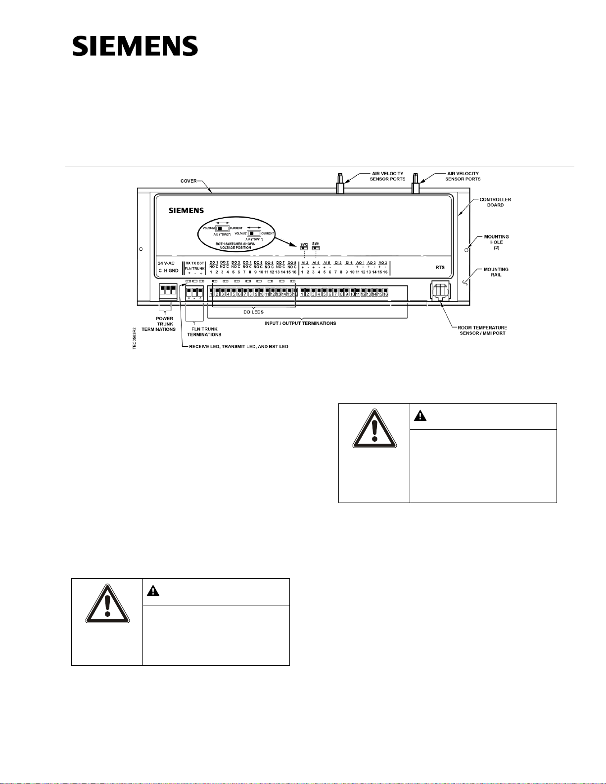
Generic Controller I/O Layout. See Wiring Diagram for application specific details.
WARNING
Personal injury/loss of life may
occur if you do not follow the
procedures as specified.
CAUTION
Equipment damage or loss of
data may occur if you do not
follow the procedures as
specified.
Siemens BACnet PTEC Dual Duct
2 AVS Controller
550-497PA
Control Applications
6665 through 6669
Product Description
These instructions explain how to field install or
replace a Siemens BACnet PTEC Dual Duct 2 AVS
Controller.
Warning/Caution Notation
Product Numbers
Shipping carton includes a controller assembly, a
mounting rail, and two self-tapping/drilling screws.
Item No. 550-139. Rev. CA Page 1 of 6
Page 2
Document No. 550-139
CAUTION
Keep the unit in its static-proof
bag until installation.
Otherwise, you run the risk of
damage to the printed circuit
board from electrostatic
discharge.
Low cost temporary
temperature sensor, 10K
thermistor with RJ11 (1”
long), that enables space
control if the permanent room
or duct sensor is not installed
(pack of 25).
540-658P25
Duct Temperature Sensor,
NTC 10K Ω Type 2, 3" Probe
for Commissioning only
QAM1030.008P50
New controller installation
10 Minutes
Replacement (old controller has
removable terminal blocks)
6 Minutes
Replacement (old controller does
not have removable terminal
blocks)
16 Minutes
NOTE:
You may require additional time for
database work at the field panel.
NOTE:
If the controller is being installed on a
box with 1 or more stages of electric
heat, the 550-809 MOV with preterminated spade connectors must be
installed across the manufacturersupplied airflow switch. MOVs can be
installed at the time the controller is
factory mounted; coordinate with the
box manufacturer prior to order
placement. For field installation, see
Metal Oxide Varistor Kit Installation
Instructions
(540-986).
NOTE:
A low-cost temporary RTS (540658P25) is available that plugs into the
RTS port on the controller, providing
temperature input and actual space
control until a permanent RTS is
installed.
NOTE:
All wiring must conform to national and
local codes and regulations (NEC, CE,
etc.).
Installation Instructions
October 26, 2016
Accessories
Room temperature sensor installed (optional).
24 Vac Class II power available.
Supply power to the unit is OFF.
Any application specific hardware or devices
installed.
Air velocity sensors installed in ducts.
Expected Installation Time
Required Tools and Equipment
Small flat-blade screwdriver (1/8-inch blade
width)
Cabling and connectors
Cordless drill/driver set
ESD wrist strap
Prerequisites
Wiring conforms to NEC and local codes and
regulations. For further information see the
Wiring Guidelines Manual
(125-3002).
Page 2 of 6 Siemens Industry, Inc.
Installation Instructions
1. Secure the mounting rail in the controller’s
desired location.
2. Place the ESD wrist strap on your wrist and
attach it to a good earth ground.
3. Remove the controller from the static proof bag
and snap it into place on the mounting rail.
Page 3

4. Connect the FLN.
CAUTION
It is very important that the
neutral that supplies the TEC
be earth grounded at the source
of the 24 Vac power.
Possible erratic equipment
operation or damage if neutral
is left floating.
CAUTION
The controller’s DOs control 24
Vac loads only. The maximum
rating is 12 VA for each DO. An
external interposing relay is
required for any of the following:
• VA requirements higher than
the maximum
• 110 or 220 Vac requirements
• DC power requirements
• Separate transformers used to
power the load
(for example part number 540147, Terminal Equipment
Controller Relay Module)
5. Connect the point wiring (see
Wiring Diagram
s).
6. Plug the room temperature sensor cable into the
RTS port.
7. Connect the power trunk. DO NOT apply power
to the controller without first consulting the
specialist. This TEC is designed to work with 2-
Document No. 550-139
Installation Instructions
October 26, 2016
Wiring Diagrams
wire AC power (Neutral and Phase (hot) at 24
Vac +/-20%. Use of the earth terminal is optional
and if used it should be connected to the nearest
earth ground (building steel, conduit or duct work
(if earthed)).)
The installation is complete.
Siemens Industry, Inc. Page 3 of 6
Page 4

Document No. 550-139
NOTE:
If the voltage/current switch is set to
current and a 4 to 20 mA sensor is
connected to an AI, then special
wiring requirements must be followed.
NOTE:
When wiring any actuator that uses a 0 to
10V control signal and ties AC neutral to DC
common, an additional wire must connect
the actuator AC neutral to the DC common
of the PTEC/TEC AO being used to control
the actuator.
Actuator
Symbol
TEC
Connection
Function
Terminal
Connection
Standard
Color
1 H Supply (SP)
G
Red
2 C Neutral (SN)
G0
Black
8
AO3 – 15
(+)
0 to 10V
input signal
Y
Gray
--
C to AO3
16 (-)
Common
jumper
--
--
Installation Instructions
October 26, 2016
Wiring for AI with a 4 to 20 mA Sensor.
24 Vac Modulating Control.
Page 4 of 6 Siemens Industry, Inc.
Page 5

Document No. 550-139
Installation Instructions
October 26, 2016
Applications 6665, 6666, 6667, and 6668 with Hot
Water Reheat.
Applications 6665, 6666, 6667, and 6668 with Electric
Auxiliary Reheat.
Siemens Industry, Inc. Page 5 of 6
Page 6

Document No. 550-139
Information in this document is based on specifications believed correct at the time of publication. The right is reserved to make changes as
design improvements are introduced. Product or company names mentioned herein may be the trademarks of their respective owners. ©
2016 Siemens Industry, Inc.
Siemens Industry, Inc.
Building Technologies Division
1000 Deerfield Parkway
Buffalo Grove, IL 60089-4513
USA
Tel. 1 + 847-215-1000
Your feedback is important to us. If you have
comments about this document, please send them
to SBT_technical.editor.us.sbt@siemens.com.
Document No.550-139
Printed in the USA
Page 6 of 6
Installation Instructions
October 26, 2016
Cyber security disclaimer
Products, solutions and services from Siemens
include security functions to ensure the secure
operation of building automation and control, fire
safety, security management, and physical security
systems. The security functions on these products,
solutions and services are important components of
a comprehensive security concept.
Drafting, implementing and managing a
comprehensive and up-to-date security concept,
customized to individual needs, is nevertheless
necessary, and may result in additional plant- or
site-specific preventive measures to ensure secure
operation of your site regarding building automation
and control, fire safety, security management, and
physical security. These measures may include, for
example, separating networks, physically protecting
system components, user training, multi-level
defensive measures, etc. For additional information
on security as part of building technology and our
product, solution and service offerings, please
contact your Siemens sales representative or project
department. We strongly recommend to always
comply with our security advisories on the latest
security threats, patches and other related
measures. http://www.siemens.com/cert/en/cert-
security-advisories.htm
Application 6669 – Variable Air Volume with
Changeover with Hot Water Reheat.
 Loading...