

Page 1

125-5093
Building Technologies
2015
-10-14
BACnet Fume Hood Controller
Vertical Sash with Damper or
Venturi Air Valve and 2-Position
Constant Volume with Damper
Owner's Manual
Page 2

Page 3

3
Siemens Industry, Inc. Owner's Manual 125-5093
Building Technologies 2015-10-14
Table of contents
How To Use This Manual .................................................................................................. 4
Chapter 1 – Product Overview ......................................................................................... 6
Hardware Inputs .................................................................................................................. 6
Hardware Outputs ................................................................................................................ 7
Ordering Notes .................................................................................................................... 7
Power Wiring ....................................................................................................................... 8
Communication Wiring ......................................................................................................... 8
Controller LED Indicators ..................................................................................................... 9
Actuators .............................................................................................................................. 9
Related Equipment .............................................................................................................. 9
Chapter 2 – Applications ................................................................................................. 10
Basic Operation ................................................................................................................. 10
Application 6740 Fume Hood Controller 2-Position Constant Volume .............................. 10
Application 6741 Fume Hood Controller Vertical Sash Configuration with Damper ......... 11
Application 6742 Fume Hood Controller Vertic al Sash Conf igur a tio n with Ve nturi Air
Valve.................................................................................................................. 12
Application 6700 Slave Mode ............................................................................................ 13
Chapter 3 – Point Database ............................................................................................ 14
Chapter 4 – Basic Service and Maintenance ................................................................ 21
Basic Service Information .................................................................................................. 21
Preventive Maintenance .................................................................................................... 21
Safety Features ................................................................................................................. 22
Glossary............................................................................................................................ 23
Index ............................................................................................................................ 27
Page 4

How To Use This Manual
4
Siemens Industry, Inc. Owner's Manual 125-5093
Building Technologies 2015-10-14
How To Use This Manual
This manual is written for the owner and user of the BACnet Fume Hood Controller. It
is designed to help you become familiar with the Siemens BACnet Fume Hood
Controller and its applications.
This section covers manual organization, manual conventions, symbols used in the
manual, and other information that will help you use this manual.
Manual Organization
This manual contains the following chapters:
Chapter 1 - Hardware,
describes the hardware components and the accessories
that are used with the BACnet Fume Hood Controller.
Chapter 2 - Applications,
describes the control applications available in the model
of the BACnet Fume Hood Controller includes a terminal block for wireable
input/output connections.
Chapter 3 - Point Database,
defines the point database descriptors and includes
address and applications.
Chapter 4 – Basic Service and Maintenance,
describes basic corrective measures
you can take should you encounter a problem when using the BACnet Fume Hood
Controller. For issues not covered in this chapter, consult your local Siemens
Industry representative.
The
Glossary
describes the terms and acronyms used in this manual.
The
Index
helps you locate information presented in this manual.
Manual Conventions
The following table lists conventions to help you use this manual in a quick and
efficient manner.
Convention
Examples
Numbered Lists (1, 2, 3…) indicate a
procedure with sequential steps.
1. Turn OFF power to the field panel.
2. Turn ON power to the field panel.
3. Contact the local Siemens Industry
representative.
Conditions that must be completed or
met before beginning a task are
designated with a
⊳
.
Intermediate results (what will happen
following the execution of a step), are
designated with a
⇨.
Results, which inform the user that a task
was completed successfully, are
designated with a
⇨.
⊳Composer software is properly installed.
⊳A Valid license is available.
1. Select
Start
>
Programs
>
Siemens
>
GMS
>
Composer
.
⇨
The Project Management window displays.
2. Open an existing project or create a new one.
⇨
The project window displays.
Actions that should be performed are
specified in boldface font.
Type F for Field panels.
Click OK to save changes and close the dialog box.
Error and system messages are
displayed in Courier New font.
The message Report Definition
successfully renamed displays in the status
bar.
New terms appearing for the first tim
e are
italicized.
The field panel continuously executes a userdefined set of instructions called the
control
program
.
Page 5
How To Use This Manual
5
Siemens Industry, Inc. Owner's Manual 125-5093
Building Technologies 2015-10-14
Convention
Examples
This symbol signifies Notes. Notes provide
additional information or helpful hints.
Cross references to other information are
indicated with an arrow and the page
number, enclosed in brackets: [→92]
For more information on creating flowcharts, see
Flowcharts [→92].
Placeholders indicate text that can vary
based on your selection. Placeholders
are specified by italicized letters, and
enclosed with brackets [ ].
Type
A C D H
[
username
] [
field panel #]
.
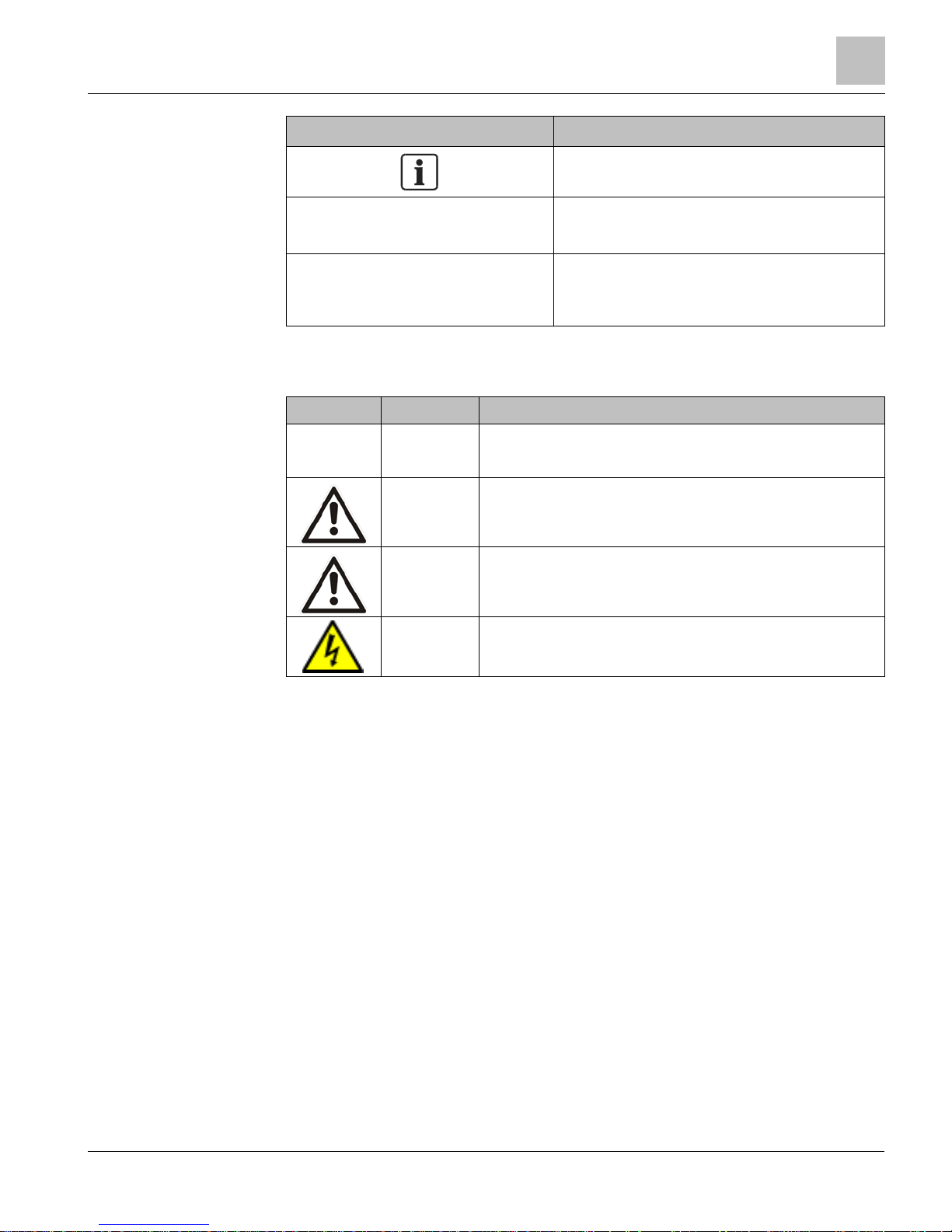
The following table lists the safety symbols used in this manual to draw attention to
important information.
Symbol
Meaning
Description
NOTICE
CAUTION
Equipment damage may occur if a procedure or instruction is not
followed as specified. (For online documentation, the NOTICE displays
in white with a blue background.)
CAUTION
Minor or moderate injury may occur if a procedure or instruction is not
followed as specified.
WARNING
Personal injury or property damage may occur if a procedure or
instruction is not followed as specified.
DANGER
Electric shock, death, or severe property damage may occur if a
procedure or instruction is not followed as specified.
Your feedback is important to us. If you have comments about this manual, please
submit them to SBT_technical.editor.us.sbt@siemens.com
Page 6

Chapter 1 – Product Overview
Hardware Inputs
6
Siemens Industry, Inc. Owner's Manual 125-5093
Building Technologies 2015-10-14
Chapter 1 – Product Overview
The Fume Hood Controller is a multi-application equipment controller designed to
provide Direct Digital Control (DDC) for various types of Variable Air Volume (VAV)
and 2-position fume hoods.
The controller can operate as an independent, stand-alone, DDC room controller or
it can be networked with a field panel.
The controller provides all termination, input/output, system and local
communication connections.
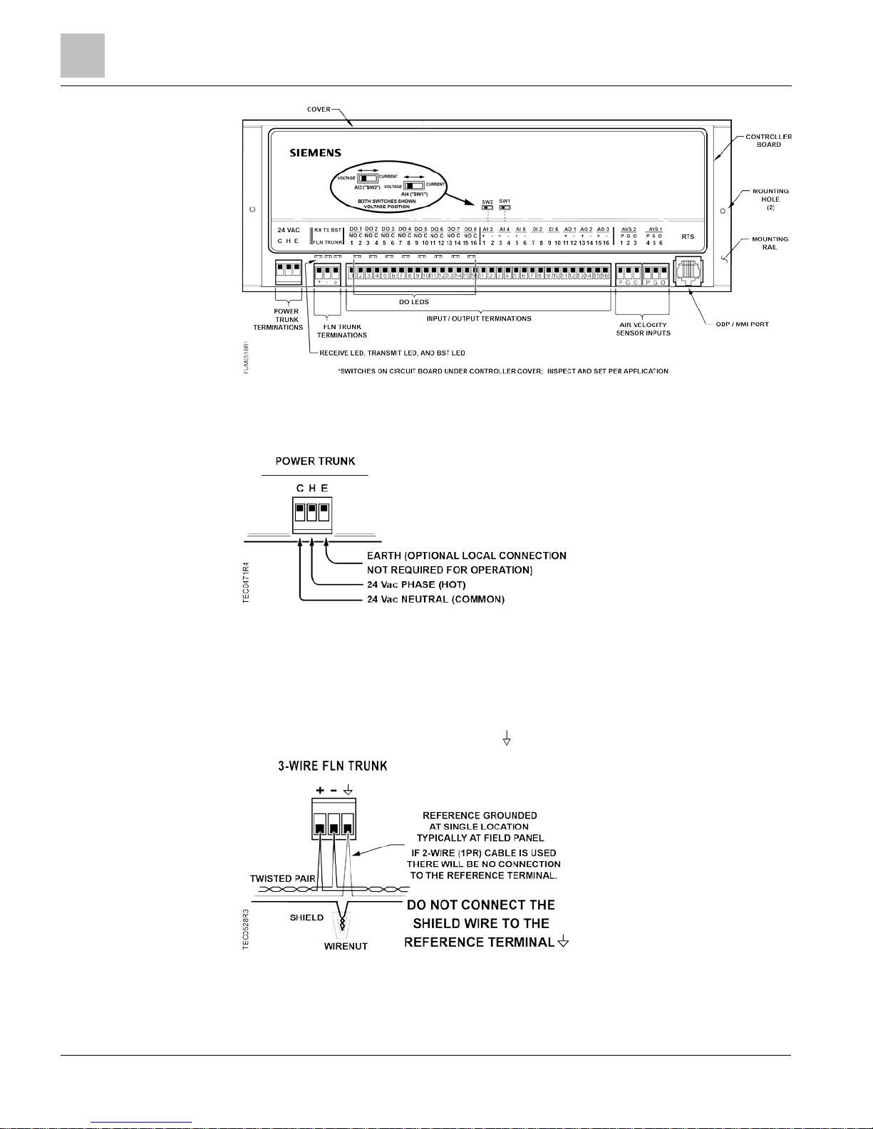
The controller hardware consists of the controller with cover and mounting bracket
(see Figure BACnet Fume Hood Controller).
The controller board is the central computing/controlling component of the system.
The following applications are covered:
Vertical Sash
Vertical Sash with Damper (Application 6741)
Vertical Sash with Venturi (Application 6742)
2-Position CV with Damper
2-Position with a Constant Volume (Application 6740)
Slave Mode (Application 6700)
Hardware Inputs
Analog
Air velocity sensor(s) – (second sensor
available for field use)
Application 6740
Application 6741
Application 6742
(Optional)
Differential pressure
transmitter/Linear Flow input (Vortex Shedder)
Application 6740
Application 6741
Application 6742
External face area Application 6741
Application 6742
Vertical sash sensor(s) Application 6741
Application 6742
Page 7

Chapter 1 – Product Overview
Hardware Outputs
7
Siemens Industry, Inc. Owner's Manual 125-5093
Building Technologies 2015-10-14
Digital
ATTN.UNATTN (through DI 2) Application 6741
Application 6742
OCC.UNOCC (through DI 2) Application 6741
Application 6742
(Optional)
High/Low select (through DI 2) Application 6740
OCC Face Velocity Setpoint (through ODP –
optional)
Application 6741
Application 6742
(Optional)
Startup Mode (through DI 4) Application 6740
(Optional)
Remote Emergency Purge (through
DI 6)
Application 6741
Application 6742
Hardware Outputs
Analog
AO 3 Analog Actuation Application 6742
Operator Display Panel (ODP) Application 6740
Application 6741
Application 6742
AO 2 (flow signal, 1 to 10 Vdc) Application 6740
Application 6741
Application 6742
Digital
Autozero Solenoid in Offboard Air Module (DO
8)
Application 6740
Application 6741
Application 6742
(Optional)
Alarm (DO 7) Application 6740
Application 6741
Application 6742
(Optional)
OFF Mode (DO 6) Application 6740
Application 6741
Application 6742
HI/LO Indication (DO 5) Application 6740
Exhaust damper (DO 1 and DO 2, Floating
Control Actuation)
Application 6740
Application 6741
Ordering Notes
BACnet Fume Hood Controller - Vertical Sash Configuration with
Damper or Venturi Air Valve, 2 Position CV with Damper
570-00701, 57000701PA
Page 8
Chapter 1 – Product Overview
Power Wiring
8
Siemens Industry, Inc. Owner's Manual 125-5093
Building Technologies 2015-10-14
Generic Controller I/O Layout. See
Wiring Diagram
for application specific details.
Power Wiring
Communication Wiring
The controller connects to the field panel by means of a Floor Level Network (FLN)
trunk. Communication wiring connects to the three screw terminals on the controller
labeled “+” (positive), “-“ (negative), and “
” (reference).
Page 9

Chapter 1 – Product Overview
Controller LED Indicators
9
Siemens Industry, Inc. Owner's Manual 125-5093
Building Technologies 2015-10-14
Controller LED Indicators
The controller has eleven Light Emitting Diode (LED) indicators (see Figure BACnet
Fume Hood Controller). Table
Controller LEDs
lists the type, the abbreviation on the
controller, and the indication of each LED.
Controller LEDs.
LED Type
Label
(if present)*
LED
Number
Indication
DO DO1 - DO8 1 – 8 Indicates the ON/OFF status of the DO
associated with it. A glowing LED indicates that
the DO is energized.
Receive RX 9 Indicates, when flashing, that the controller is
receiving information from the field panel.
Transmit TX 10 Indicates, when flashing, that the controller is
transmitting information to the field panel.
BST
”Basic Sanity
Test”
BST 11 Indicates, w
hen flashing ON and OFF once per
second, that the controller is functioning
properly.
Actuators
Actuators used with the BACnet Fume Hood Controller include electronic damper
motor. This actuator is controlled by the controller to position the damper or air valve.
Related Equipment
Operator Display Panel (ODP)
Sash sensors
Laboratory Exhaust Air Terminal
Differential Pressure Transmitter
Venturi air valves
Air flow sensors
Contact your local Siemens Industry representative for product numbers and more
information.
Page 10

Chapter 2 – Applications
Basic Operation
10
Siemens Industry, Inc. Owner's Manual 125-5093
Building Technologies 2015-10-14
Chapter 2 – Applications
Basic Operation
The BACnet Fume Hood controller provides Direct Digital Control (DDC) technology for
pressure independent Variable Air Volume (VAV) and Constant Volume (CV)
laboratory fume hood applications.
Application 6740 Fume Hood Controller 2-Position
Constant Volume
This application is designed for use with a constant volume or two-position fume hood
in a manifold fume hood exhaust system. Two-position fume hoods have an individual
exhaust damper connected to a central fan. The application modulates the exhaust
flow control device to maintain a high or low flow setpoint based on inputs from the
ODP (Operator’s Display Panel), digital input, an exhaust airflow sensor, and the
controller setpoints.
Application 6740 Control Diagram.
Page 11

Chapter 2 – Applications
Application 6741 Fume Hood Controller Vertical Sash Configuration with Damper
11
Siemens Industry, Inc. Owner's Manual 125-5093
Building Technologies 2015-10-14
Application 6741 Fume Hood Controller Vertical Sash
Configuration with Damper
Application 6741 and Application 6742 are designed for use with a wide range of fume
hood sash configurations connected to a manifold fume hood exhaust system. The
sash configurations include:
Bench style fume hoods – single vertical sash
Dual Bench style fume hoods – side-by-side single vertical sash
Floor Mounted style fume hoods – two vertical sashes, one on top of the other
WARNING
The application cannot detect a broken wire to the analog input for the second sash.
An external sash aggregating device should be used to calculate the face area for all
fume hoods with more than one sash.
Application 6741 Control Drawing.
Page 12

Chapter 2 – Applications
Application 6742 Fume Hood Controller Vertical Sash Configuration with Venturi Air Valve
12
Siemens Industry, Inc. Owner's Manual 125-5093
Building Technologies 2015-10-14
Application 6742 Fume Hood Controller Vertical Sash
Configuration with Venturi Air Valve
Application 6741 and Application 6742 are designed for use with a wide range of fume
hood sash configurations connected to a manifold fume hood exhaust system. The
sash configurations include:
Bench style fume hoods – single vertical sash
Dual Bench style fume hoods – side-by-side single vertical sash
Floor Mounted style fume hoods – two vertical sashes, one on top of the other
WARNING
The application cannot detect a broken wire to the analog input for the second sash.
An external sash aggregating device should be used to calculate the face area for all
fume hoods with more than one sash.
Application 6742 Control Drawing.
Page 13

Chapter 2 – Applications
Application 6700 Slave Mode
13
Siemens Industry, Inc. Owner's Manual 125-5093
Building Technologies 2015-10-14
Application 6700 Slave Mode
Application 6700 is the slave mode application for the BACnet Fume Hood Controller
(see
Ordering Notes
for product numbers). Slave mode is the default application that
comes up when power is first applied to the controller. Slave mode provides no control.
Its purpose is to allow the operator to perform equipment checkout before a control
application is put into effect and to set some basic controller parameters (CTLR
ADDRESS, APPLICATION, and so on).
Page 14

Chapter 3 – Point Database
14
Siemens Industry, Inc. Owner's Manual 125-5093
Building Technologies 2015-10-14
Chapter 3 – Point Database
Chapter 3 presents a description of the BACnet Fume Hood Controller point database,
including point descriptors, point addresses, and a listing of applications in which each
point is found.
Descriptor
Address1
Application
Description
CTLR ADDRESS 01 All Identifies the controller on the FLN trunk.
APPLICATION 02 All Identifies the program running in the controller.
FACE VEL 04 6741, 6742 The calculated average air velocity through the face of the
fume hood.
LOW ALM 05 6740, 6741, 6742 Displays an ON or OFF status. When the face velocity goes
below the value specified at LOW ALM LMT for the time
specified in ALARM TIME, the point goes into an alarm state
(ON); the red LED is illuminated, the alarm sounds, and the
message LOW Face Velocity displays at the ODP.
(Application 6740 uses exhaust flow.)
HIGH ALM 06 6740, 6741, 6742 Displays an ON or OFF status. When the face velocity goes
above the value specified at HI ALM LMT for the item
specified in ALARM TIME, the point goes into an alarm state
(ON); the red LED is illuminated, the alarm sounds, and the
message HIGH FACE VELOCITY displays at the ODP.
(Application 6740 uses exhaust flow.)
EMER ALM 07 6740, 6741, 6742 Displays an ON or OFF status that indicates if the
EMERGENCY PURGE button on the ODP has been
pressed. When the operator presses the EMERGENCY
PURGE button, the point is ON, the red LED is illuminated,
the alarm sounds, and EEE and EMERGENCY MODE
display at the ODP. If pressed again, then the point is OFF.
This point can be commanded by a field panel.
GEN FAILURE 08 6740, 6741, 6742 Indicates a hardware failure (for example, the sash sensor)
with an ON or OFF status. The red LED is illuminated; the
alarm sounds, and FFF and GENERAL FAILURE display at
the ODP.
HI ALM LMT 10 6740, 6741, 6742 The value above FVEL STPT, in percent, at which the red
LED and audible alarm are activated on the ODP. This point
is the setpoint for HIGH ALM. Valid values: 100 through
255%. (Application 6740 uses EXH STPT.)
HI WARN LMT 11 6740, 6741, 6742 The value above FVEL STPT, in percent, at which the yellow
LED is illuminated on the ODP. Valid values: 100 through
255%. (Application 6740 uses EXH STPT.)
LOW WARN LMT 12 6740, 6741, 6742 The value below FVEL STPT, in percent, at which the yellow
LED is illuminated on the ODP. Valid values: 0 through
100%. (Application 6740 uses EXH STPT.)
LOW ALM LMT 13 6740, 6741, 6742 The value below FVEL STPT, in percent, at which the red
LED and audible alarm activates on the ODP. This point is
the setpoint for LOW ALM. Valid values: 0 through 100%.
(Application 6740 uses exhaust flow.)
EMER TIMER 14 6740, 6741, 6742 When EMER ALM is set to ON, the time set for EMER
TIMER is used as the length of time the EXH FLOW is
commanded to full flow (the damper is full open). After the
time in EMER TIMER times out, the EXH FLOW is controlled
to the value set in EMER STPT. Valid values: 0 through 32,
Page 15

Chapter 3 – Point Database
15
Siemens Industry, Inc. Owner's Manual 125-5093
Building Technologies 2015-10-14
Descriptor
Address1
Application
Description
767 seconds.
EMER STPT 15 6740, 6741, 6742 A value of the preset FVEL STPT, in percent, that the
controller uses as the setpoint when EMER ALM is ON.
(Application 6740 uses EXH STPT.)
LOW WARN 16 6740, 6741, 6742 Displays an ON or OFF status. When the face velocity goes
below the value specified at LOW WARN LMT for the time
specified in ALARM TIME, the point goes into a warning
state (ON); the yellow LED is illuminated at the ODP.
HIGH WARN 17 6740, 6741, 6742 Displays an ON or OFF status. When the face velocity goes
above the value specified at HI WARN LMT for the time
specified in ALARM TIME, the point goes into a warning
state (ON), the yellow LED is illuminated at the ODP.
ALARM TIME 18 6740, 6741, 6742 Time delay for the red and yellow alarm LEDs used to
eliminate sudden changes and false alarms. The average
face velocity must rise above any of the set limits (for
example, HI ALM LMT) for the amount of time specified at
this point before the ODP indicates an alarm condition.
FLOW MAX 18 6741, 6742 Maximum flow setpoint allowed. FLOW MAX will override the
FVEL STPT if the calculated FLOW STPT is greater than
FLOW MAX.
ALM AKNLG 19 6740, 6741, 6742 Displays an ON or OFF status that indicates the Horn
Silence button has been pressed at the ODP to acknowledge
an alarm condition. The point will reset when the alarm
condition clears or another alarm is initiated.
OCC.UNOCC 20 6741, 6742
OCC or UNOCC point controls which face velocity setpoint to
use; OCC FV SET or UNOCC FV SET.
STARTUP MODE 21 6740, 6741, 6742 Toggles the ODP from normal operation to OFF mode. In
OFF mode, the alarms do not sound, the ODP displays OFF
and the RED LED is on.
LEFT SWITCH 22 6741, 6742, 6700 Indicates if the left auxiliary button on the ODP has been
pressed. This is a toggle action digital input; when pressed,
the point is ON. If pressed again, the point is OFF.
ODP STPT SW 22 6740 Indicates if the left button on the ODP has been pressed.
This is a toggle action digital input; when pressed, the
controller changes between HI and LOW flow setpoints.
RIGHT SWITCH 23 All Indicates if the right auxiliary button on the ODP has been
pressed. This is a toggle action digital input; when pressed,
the point is ON. If pressed again, the point is OFF.
ATN.UNATTN 24 6741, 6742 ATTN or UNATTN point controls the mode of operation for
the sash alert function.
AT ALRT AREA 25 6741, 6742 The open area in square feet (SQM) at which the Sash Alert
feature will start beeping the horn during attended operation.
UN ALRT AREA 26 6741, 6742 The open area in square feet (SQM) at which the Sash Alert
feature will start beeping the horn during unattended
operation.
OPEN TIME 27 6741, 6742
When SASH OP ALRT is on, you can silence the alert for the
time entered in OPEN TIME.
SASH TONE 28 6741, 6742 ON or OFF point controls if the ODP will beep for the SASH
ALRT function or if the alarm will just be passed to the
network.
SASH OP ALRT 30 6741, 6742 This point turns ON when the face area is larger than UN
Page 16

Chapter 3 – Point Database
16
Siemens Industry, Inc. Owner's Manual 125-5093
Building Technologies 2015-10-14
Descriptor
Address1
Application
Description
ALRT AREA or AT ALRT AREA depending on the state of
ATTN.UNATTN.
EXH VOL 31 All The calculated value, in CFM (LPS), of the exhaust airflow.
FLOW COEF 32 All Gain factor for the flow sensor.
DUCT AREA 33 All Area of the duct, in square feet (SQM), where the air velocity
sensor is located.
TRANS RANGE 34 6740, 6741, 6742 The maximum range, in inches of water (PA), of the
differential pressure transmitter. Standard values are 0.1
(25.3), 0.25 (62.275), 0.5 (124.55), and 1.0 (253).
LINEAR FL RG 35 6740, 6741, 6742 When AI 3 is used as a linear flow sensor input, this value is
the maximum range of the input.
AVS2 PRESS 36 All The pressure that is applied to AVS2.
DI 2 37 6741, 6742, 6700 Actual status of a contact connected to the controller at DI 2.
ON indicates that the contact is closed; OFF indicates that
the contact is open. If a wall switch is used, it is connected to
DI 2.
DI 2 STPT SW 37 6740 Digital input for dry contact connection to control the HI/LOW
flow setpoint of the controller.
DI 6 38 All Actual status of a contact connected to the controller. ON
indicates that the contact is closed; OFF indicates that the
contact is open. Actual status of a contact connected to the
controller. ON indicates that the contact is closed; OFF
indicates that the contact is open.
AO 1 39 All Spare analog output is a 0 to 10 Vdc output.
AO 3 40 6740, 6741, 6700 Spare analog output is a 0 to 10 Vdc output.
EXH AO3 40 6742 Control signal for Venturi General Exhaust Valve (0 - 10V).
EXH DO1 41 6740, 6741 Digital output 1 and 2 are used to control a floating point
actuator.
DO 1 41 6742, 6700 Spare digital output controls a 24 Vdc load with an ON or
OFF status.
RETC DO 2 42 6740, 6741 Digital output 1 and 2 are used to control a floating point
actuator.
DO 2 42 6742, 6700 Spare digital output controls a 24 Vdc load with an ON or
OFF status.
DO 3 43 All Spare digital output controls a 24 Vdc load with an ON or
OFF status.
DO 4 44 All Spare digital output controls a 24 Vdc load with an ON or
OFF status.
DO 5 45 6741, 6742, 6700 Spare digital output controls a 24 Vdc load with an ON or
OFF status.
HI.LOW DO5 45 6740 Digital output that follows the HI/LOW flow setpoint.
DECOM DO6 46 6740, 6741, 6742 Digital output that turns on when a decommissioned hood is
used.
DO 6 46 6700 Spare digital output controls a 24 Vdc load with an ON or
OFF status.
ALARM DO7 47 6740, 6741, 6742 Intended to drive local alarm device (horn, light, and so on.).
Function set up by setting alarm enable points.
Page 17

Chapter 3 – Point Database
17
Siemens Industry, Inc. Owner's Manual 125-5093
Building Technologies 2015-10-14
Descriptor
Address1
Application
Description
DO 7 47 6700 Spare digital output controls a 24 Vdc load with an ON or
OFF status.
AUTOZERO DO8 48 6740, 6741, 6742 Drives the Offboard Air Module(s) in order to calibrate the
flow sensor(s). Do not use or manually set this point.
DO 8 48 6700 Spare digital output controls a 24 Vdc load with an ON or
OFF status.
AI 3 49 6741, 6742 Optional input for External Face Area or Airflow sensor.
AI 3 49 6700, 6740 Optional input for Airflow sensor or spare analog input (0 –
10V or 4-20 mA).
AI 4 50 6741, 6742 Sash sensor 2 input or spare analog input (0 - 10V or 4-20
mA).
AI 4 50 6700,, 6740 Startup DI 4 (Point 56) or spare analog input (0 – 10V or 4-20
mA).
AI 5 51 6741, 6742 Sash sensor 1 input.
AI 5 51 6700, 6740 Spare analog input, 10K Ω.
VERT SASH1 52 6741, 6742 Current position, in inches (cm), of the vertical sash wired as
sash 1 at the controller board. If not physically wired to the
controller, this point may display as 'failed'.
VERT SASH2 53 6741, 6742 Current position, in inches (cm), of the vertical sash wired as
sash 2 at the controller board. If not physically wired to the
controller, this point may appear as 'failed'.
FACE AREA 54 6741, 6742 The open area, in square feet (SQM), of the fume hood face,
which includes the fixed area and accounts for the bypass
area.
CAL SASH POS 55 6741, 6742
User defined value used during calibration of the sash sensor
to describe the current position of the sash, in inches (cm).
CAL SASH LOC 56 6741, 6742 User defined value (MIN or MAX) used during the calibration
sequence to indicate if the minimum or maximum sash
position is being calibrated.
DI 4 56 6740 DI determines if DI 4 is used to change the STARTUP
MODE.
CAL SASH NUM 57 6741, 6742 The number of the sash being calibrated. Valid values: 1 to
5.
DMPR COMD 58 6740, 6741, 6742 The commanded position of the damper.
INVERT DO2 59 6740, 6741 Setting to NCLOSE allows the controller to operate industry
standard floating control actuators. Setting this point may
stop the failsafe operation from functioning.
AVS FAILMODE 60 6740, 6741, 6742 Indicates the desired position of the damper if the airflow
sensor(s) fail.
Valid values: CLOSED or OPEN.
EXH P GAIN 61 6740, 6741, 6742 The proportional gain value for the fume hood flow control
loop.
EXH I GAIN 62 6740, 6741, 6742 The integral gain value for the fume hood flow control loop.
EXH D GAIN 63 6740, 6741, 6742 The derivative gain value for the fume hood flow control loop.
FIXED AREA 64 6741, 6742 Open area of the fume hood, in square feet (SQM), that
remains the same regardless of sash position.
VERT WIDTH1 65 6741, 6742 Defines the overall width of the vertical sash wired to sash 1
Page 18

Chapter 3 – Point Database
18
Siemens Industry, Inc. Owner's Manual 125-5093
Building Technologies 2015-10-14
Descriptor
Address1
Application
Description
at the controller board.
VERT WIDTH2 66 6741, 6742 Defines the overall width of the vertical sash wired to sash 2
at the controller board.
VSASH HGHT1 67 6741, 6742
Defines the overall height of the vertical sash wired to sash 1
at the controller board.
VSASH HGHT2 68 6741, 6742
Defines the overall height of the vertical sash wired to sash 2
at the controller board.
TRACK HEIGHT 69 6741, 6742 Measurement, in inches (cm), of the vertical track in a multi-
vertical sash fume hood.
BYPASS HGHT 70 6741, 6742 The height of the bypass opening of the fume hood.
BYPASS OPEN 71 6741, 6742 The effective bypass area in percent.
FAIL AREA 72 6741, 6742 When a sash sensor fails, the controller controls to the face
area defined by this point.
EXTERNAL A 73 6741, 6742
When AI 3 is used to input an external face area, the value is
displayed here.
MAX EXT AREA 74 6741, 6742 Scaling for the external face area Analog Input (AI 3) point.
MIN EXTVOLTS 75 6741, 6742 Minimum voltage value for external face area input range
(typically 0.0V or 1.0V).
CAL EXH VLV 78 6742 YES or NO point used to calibrate EXH AO3 to the
associated flow rate.
STARTUP DI4 78 6740 Determines if DI4 is used to change the STARTUP MODE.
EXH VLV STAT 79 6742 PASS or FAIL point used to indicate if the last calibration
attempt passed.
EXH MAX 80 6741, 6742, 6700 Maximum flow setpoint allowed. EXH MAX will override the
FVEL STPT if the calculated FLOW STPT is greater than
EXH MAX.
EXH HI STPT 80 6740 The high flow setpoint used in EXH STPT.
EXH MIN 81 6741, 6742, 6700 Minimum flow setpoint allowed. EXH MIN will override the
FVEL STPT if the calculated FLOW STPT is less than EXH
MIN.
EXH LO STPT 81 6740 The low flow setpoint used in EXH STPT.
FVEL STPT 83 6741, 6742 The face velocity setpoint in feet per minute (m/s) that is
maintained by the Fume Hood Controller. Valid values: 0
through 225 ft/min (0-1.2954 m/s).
OCC FV SET 84 6741, 6742 The face velocity setpoint during occupied operation.
UNOC FV SET 85 6741, 6742 The face velocity setpoint during unoccupied operation.
OCC LOW FV 86 6741, 6742
(Optional)
The low face velocity setpoint during occupied
operation.
OCC HIGH FV 87 6741, 6742
(Optional)
The high face velocity setpoint during occupied
operation.
OCC DELAY 88 6741, 6742 This point delays the OCC.UNOCC function, a user defined
number of seconds, when the controller is in UNATTN mode.
EXH SIG AO2 89 6740, 6741, 6742 Indicates the exhaust flow setpoint. The output is 1 to 10
Vdc, which corresponds to 0 to AO2 RANGE.
AO2 89 6700 Spare analog output is a 9 to 10 Vdc output.
Page 19

Chapter 3 – Point Database
19
Siemens Industry, Inc. Owner's Manual 125-5093
Building Technologies 2015-10-14
Descriptor
Address1
Application
Description
AO2 RANGE 90 6741, 6742 Scaling for the Analog Output (AO2) point. To get the correct
output, the slope and intercept of this point must match the
point database of the room controller.
AO2 DEADBAND 91 6740, 6741, 6742 When EXH FLOW and FLOW STPT are different by more
than the AO2 DEADBAND, the AO2 FLOW SIG changes
from setpoint to actual flow.
AO2 V MIN 92 6740, 6741, 6742 Minimum voltage value for fume hood output range (typically
0.0V or 1.0V).
CAL AIR 94 All YES commands the controller to go through calibration
sequence for the air velocity transducers. YES is also
displayed when the calibration sequence is started
automatically. CAL AIR automatically returns to NO after the
calibration sequence is completed. Valid input: YES or NO.
CAL SETUP 95 All The configuration setup code for the calibration sequence
options.
CAL TIMER 96 All Time interval, in hours, between the calibration sequence
initiations if a timed calibration option is selected in CAL
SETUP.
AVS1 PRESS 97 All The pressure that is applied to AVS1.
LOOP TIME 98 6741, 6742 The time, in tenths of a second, between control loop
calculations.
ERROR STATUS 99 All The status code that indicates any errors detected during
controller power-up.
DISPLAY WT 106 6740, 6741, 6742 Factor used to filter out large changes in the value of FACE
VEL that is displayed at
the ODP. This value is a percent that
is used to average a portion of the current average face
velocity with a portion of the previous average face velocity.
The value of this point is a percentage of the current average
face velocity. (Application 6740 uses EXH VOL.)
DISPLAY RES 107 6740, 6741, 6742 A change of value (COV) limit for the face velocity displayed
at the ODP. The display does not update unless the change
in face velocity exceeds this value.
BLANK DISPLY 108 6740, 6741, 6742 When set to YES, the face velocity does not display at the
ODP.
LAMP TEST 109 6740, 6741, 6742 Turns on all lights, prompts, and the audible alarm at the
ODP.
ENG UNITS 110 6740, 6741, 6742 Toggles the display of the ODP from feet per minute to
meters per second. Toggling this point does not change the
displayed value at the portable operator's terminal.
TABLE VOLTS 118 6740, 6741, 6742 The database point used to view and edit the internal Venturi
calibration data.
TABLE FLOW 119 6740, 6741, 6742 The database point used to view and edit the internal Venturi
calibration data.
V TABLE PT 120 6740, 6741, 6742 The database point used to view and edit the internal Venturi
calibration data.
HI LIMIT 121 6740, 6741, 6742 Determines when the flow PID will “coast” if near setpoint.
LO LIMIT 122 6740, 6741, 6742 Determines when the flow PID will “coast” if near setpoint.
EMER DI6 123 6740, 6741, 6742 Remote initiation of the Emergency Purge functionality.
OPEN LOOP 124 6742 The controller does not use feedback to reposition the air
Page 20

Chapter 3 – Point Database
20
Siemens Industry, Inc. Owner's Manual 125-5093
Building Technologies 2015-10-14
Descriptor
Address1
Application
Description
valve.
ODP DISPLAY 125 6740 Controls the function of the ODP display. It will display either
CFM divided by 10 or HI FLOW / LO FLOW.
AVE FACE VEL 126 6741, 6742 The filtered face velocity that displays on the ODP.
AVE EXH VOL 126 6740 The filtered exhaust volume that displays on the ODP.
PPCL STATE 127 6740, 6741, 6742 Indicates that customized programming has been added in
addition to the normal control strategy of the application
being used. This point is read as LOADED or EMPTY. A
status of LOA
DED indicates that there is PPCL programming
in the controller, and it is providing unique control to meet a
customer's job specification. A status of EMPTY indicates
that no unique programming is present.
1)
Points not listed are not used in this application.
Page 21

Chapter 4 – Basic Service and Maintenance
Basic Service Information
21
Siemens Industry, Inc. Owner's Manual 125-5093
Building Technologies 2015-10-14
Chapter 4 – Basic Service and Maintenance
This chapter describes corrective measures you can take should you encounter a
problem when using a BACnet Fume Hood Controller.
You are not required to do any controller troubleshooting. You may want to contact
your local Siemens Industry representative if a problem occurs or you have any
questions about the controller.
NOTE:
When troubleshooting, record the problem and what actions were performed
immediately before the problem occurred. Being able to describe the problem in detail
is important should you need assistance from your local Siemens Industry
representative.
Basic Service Information
Always remove power to the BACnet Fume Hood Controller when installing or
replacing it. Since the controller does not have a power switch, the recommended
method of removing power to a locally powered controller is to turn OFF the power to
the 24 Vac transformer. The recommended method of removing power to a controller
on a power cable (even to service a single controller) is to turn OFF the power at the
transformer.
NOTE:
When removing power to a controller to perform maintenance or service, make sure
that the person in charge of the facility is aware of this and that appropriate steps are
taken to keep the building in control.
Never remove the cover from the BACnet Fume Hood Controller. There are no
serviceable parts inside. If a problem is found with this device, contact your local
Siemens Industry representative for replacement. An anti-static wrist strap is
recommended when installing or replacing controllers.
Preventive Maintenance
Most controller components are designed so that, under normal circumstances, they
do not require preventive maintenance. Periodic inspections, voltage checks, and point
checks are normally not required. The rugged design makes most preventive
maintenance unnecessary. However, devices that are exposed to dusty or dirty
environments may require periodic cleaning to function properly.
Page 22

Chapter 4 – Basic Service and Maintenance
Safety Features
22
Siemens Industry, Inc. Owner's Manual 125-5093
Building Technologies 2015-10-14
Safety Features
The controller board stores the controller's address, applications, and point values. In
the event of a power failure or a reset, these values are retrieved from the controller's
permanent memory and are used by the controller unless overridden by a field panel. If
one of the following conditions occurs, the controller will activate safety features
present in its fail-safe mode.
Sensor failure.
Loss of power. Upon controller power loss, communication with the controller is
also lost. The controller will appear as failed (*F*) at the field panel.
Page 23

Glossary
23
Siemens Industry, Inc. Owner's Manual 125-5093
Building Technologies 2015-10-14
Glossary
This glossary contains the collected terms and acronyms that are used in Siemens
BACnet PTEC and TEC Controllers. For definitions of point database descriptors, see
Chapter 3 - Point Database, in this manual.
airflow
Rate at which a volume of air moves through a duct. Usually expressed in cubic feet
per minute (cfm) or liters per second (lps).
algorithm
Mathematical formula and control logic that uses varying inputs to calculate an output
value.
AVS
Air Velocity Sensor. An electronic device that converts differential pressure from a pilot
tube or multi-point pickup to an analog rate of fluid flow (air velocity in fpm, m/s) to
provide calculations of air volume rate (cfm, lps) in a duct. The air velocity sensor may
be an external device or an internal component of a controller.
centralized control
Type of control offered by a controller that is connected by means of Field Level
Network (FLN).
cfm
Cubic Feet per Minute.
Chilled Beam
A cooling device that provides a cooling system by taking care of both the sensible and
latent heat gains of a room in a single package by a series of chilled water coils
mounted near or in the ceiling. Coupled with a CV or VAV terminal ventilation system,
a chilled beam induces air movement over the coil in the way that it discharges fresh
air into the room. This allows for both fresh air and cooling to be taken care of at the
same time.
control loop
An algorithm, such as PI or PID, that is used to control an output based on a setpoint
and an input reading from a sensor.
CO2
Carbon dioxide, a naturally occurring chemical compound composed of two oxygen
atoms and a single carbon atom. Among other production sources, carbon dioxide is
produced as the result of breathing of humans and animals and can therefore be an
indirect indication of the concentration of humans in a zone.
CV
Constant air volume. Ventilation system that provides a fixed air volume supplied to
and exhausted from the rooms served. The fixed volume may be different during
occupied and unoccupied times
Page 24

Glossary
24
Siemens Industry, Inc. Owner's Manual 125-5093
Building Technologies 2015-10-14
Demand Control Ventilation
A control algorithm that provides for the control or reduction of outdoor air intake below
design rates when the actual occupancy of spaces served by the system is at less than
design occupancy.
DCV
Demand Control Ventilation.
DDC
Direct Digital Control.
Direct digital control
The automated control of a condition or process by a digital device (computer).
DO
Digital Output. Physical output point that sends a two-state signal (ON/OFF,
OPEN/CLOSED, YES/NO).
English units
The foot-pound-second system of units for weights and measurements.
equipment controller
FLN device, such as a BACnet PTEC or ATEC, that provides individual room or
mechanical equipment control or additional point capacity to a field panel.
field panel
A DDC control device containing a microprocessor for centralized control and
monitoring of system components and equipment controllers.
Floating Control
The combination of a modulating controlled device with the use of a pair of two position
outputs. The control signal will either activate one or the other outputs to drive the
controlled device towards its open or closed position. When both outputs are off, the
controlled device maintains its last position. Also referred to as tri-state control.
FLN
Field Level Network. Network consisting of equipment controllers, FLN end devices,
fume hoods, and so on.
lps
Liters per Second.
loopout
Output of the control loop expressed as a percentage.
Heat pump
An HVAC device used for both space heating and space cooling. When a heat pump is
used for heating, it employs the same basic refrigeration-type cycle used by an air
conditioner but in the opposite direction, releasing heat into the conditioned-space
rather than the surrounding environment. In this use, heat pumps generally draw heat
from the cooler external air or from the ground.
Page 25

Glossary
25
Siemens Industry, Inc. Owner's Manual 125-5093
Building Technologies 2015-10-14
HMI
Human Machine Interface. Terminal and its interface program that allows you to
communicate with a field panel or equipment controller.
Occupancy sensor
A control device that detects presence of people in a space by using infrared or
ultrasonic technology. Occupancy sensors are used to save energy by controlling
lighting and temperature and, along with CO2 sensors, to provide control input of
demand control ventilation (DCV) algorithms.
override switch
Button on a room temperature sensor that an occupant can press to change the status
of a room from unoccupied to occupied (or from night to day) for a predetermined time.
pressure dependent
Variable Air Volume (VAV) room temperature control system in which the temperature
drives a damper such that the air volume delivered to the space at any damper position
is dependent on the duct static pressure.
pressure independent
Variable Air Volume (VAV) room temperature control system in which the temperature
drives an airflow setpoint such that the air volume delivered to the space is
independent of variations in the duct static pressure.
PID
Proportional, Integral, Derivative.
RTS
Room Temperature Sensor.
setpoint
Data point that stores a value such as a temperature setting. In contrast, points that
monitor inputs, such as temperature, report actual values.
SI units
Systeme International d'Unites. The international metric system.
slave mode
Default application that displays when power is first applied to an equipment controller.
No control action is initiated in the slave mode. Input and output points in the slave
application can be monitored or controlled by a field panel (or by PPCL in a BACnet
PTEC controller).
stand-alone control
Type of control offered by a controller that is providing independent DDC control to a
space.
Terminal Equipment Controller
Siemens Industry, Inc. product family of equipment controllers that house the
applications software used to control terminal units, such as heat pumps, VAV terminal
boxes, fan coil units, unit ventilators, and so on.
Page 26

Glossary
26
Siemens Industry, Inc. Owner's Manual 125-5093
Building Technologies 2015-10-14
UI
Universal Input. Can be used as an AI or DI. An AI input is a point receiving a signal
that represents a condition that has more than two states. A DI input is a physical input
point that receives a two-state signal.
unbundle
Term used to describe the entering of a point that resides in a controller's database
into the field panel's database so that it can be monitored and controlled from the field
panel.
VAV
Variable air volume. Ventilation system that changes the amount of air supplied to and
exhausted from the rooms served.
Page 27

Index
27
Siemens Industry, Inc. Owner's Manual 125-5093
Building Technologies 2015-10-14
Index
A
actuators, 9
damper actuator, 9
valve actuator, 9
algorithm, 23
application, slave mode
overview, 13
B
basic operation, 10
basic service information, 21
C
centralized control, 23
Chilled Beam, 23
CO2, 23
control loop, 23
CV, 23
D
DCV, 24
DDC, 24
Demand Control Ventilation, 24
Direct digital control, 24
Direct Digital Control (DDC), 10
DO, 24
E
English units, 24
equipment controller, 24, 25
F
field panel, 6
FLN, 24
Floating Control, 24
Floor Level Network (FLN), 8
H
hardware
actuators, 9
LEDs, 9
L
LED, 9
loopout, 24
M
mounting bracket, 6
O
override switch, 25, 25
P
PID, 25
point database
overview, 14
preventive maintenance, 21
R
RTS, 25
S
safety features, 22
service information, basic, 21
setpoint, 25
SI units, 25
slave mode, 25
slave mode application, 13
stand-alone, 6
stand-alone control, 25
static discharge, 21
T
troubleshooting, 21
basic service information, 21
U
unbundle, 26
units, English, 24
Page 28

Issued by
Siemens Industry, Inc.
Building Technologies Division
1000 Deerfield Pkwy
Buffalo Grove IL 60089
Tel. +1 847-215-1000
© Siemens Industry, Inc., 2015
Technical specifications and availability subject to change without notice.
Document ID 125-5093 125-5093(BA)
Edition 2015-10-14
 Loading...