

Page 1
SIMOGEAR gearbox
BA 2030
Operating Instructions · 06/2012
SIMOGEAR
Answers for industry.
Page 2

Page 3

_
_
_
_
_
_
_
_
_
_
_
_
_
_
_
_
_
_
_
_
_
_
_
_
BA 2030
SIMOGEAR
Gearbox
BA 2030
Operating Instructions
General information and
_________________
safety notes
_________________
Technical description
Incoming goods, transport,
_________________
and storage
_________________
Installation
_________________
Commissioning
_________________
Operation
_________________
Faults, causes and remedies
_________________
Service and maintenance
_________________
Disposal
_________________
Technical data
_________________
Spare parts
_________________
Declaration of Incorporation
1
2
3
4
5
6
7
8
9
10
11
12
Original Operating Instructions
06/12
70000004040207
Page 4

Legal information
Legal information
Warning notice system
This manual contains notices you have to observe in order to ensure your personal safety, as well as to prevent
damage to property. The notices referring to your personal safety are highlighted in the manual by a safety alert
symbol, notices referring only to property damage have no safety alert symbol. These notices shown below are
graded according to the degree of danger.
DANGER
indicates that death or severe personal injury will result if proper precautions are not taken.
WARNING
indicates that death or severe personal injury may result if proper precautions are not taken.
CAUTION
with a safety alert symbol, indicates that minor personal injury can result if proper precautions are not taken.
NOTICE
without a safety alert symbol, indicates that property damage can result if proper precautions are not taken.
If more than one degree of danger is present, the warning notice representing the highest degree of danger will
be used. A notice warning of injury to persons with a safety alert symbol may also include a warning relating to
property damage.
Qualified Personnel
The product/system described in this documentation may be operated only by personnel qualified for the specific
task in accordance with the relevant documentation, in particular its warning notices and safety instructions.
Qualified personnel are those who, based on their training and experience, are capable of identifying risks and
avoiding potential hazards when working with these products/systems.
Proper use of Siemens products
Note the following:
WARNING
Siemens products may only be used for the applications described in the catalog and in the relevant technical
documentation. If products and components from other manufacturers are used, these must be recommended
or approved by Siemens. Proper transport, storage, installation, assembly, commissioning, operation and
maintenance are required to ensure that the products operate safely and without any problems. The permissible
ambient conditions must be complied with. The information in the relevant documentation must be observed.
Trademarks
All names identified by ® are registered trademarks of Siemens AG. The remaining trademarks in this publication
may be trademarks whose use by third parties for their own purposes could violate the rights of the owner.
Disclaimer of Liability
We have reviewed the contents of this publication to ensure consistency with the hardware and software
described. Since variance cannot be precluded entirely, we cannot guarantee full consistency. However, the
information in this publication is reviewed regularly and any necessary corrections are included in subsequent
editions.
Siemens AG
Industry Sector
Postfach 48 48
90026 NÜRNBERG
GERMANY
70000004040207
Ⓟ 07/2012 Technical data subject to change
Copyright © Siemens AG 2012.
All rights reserved
Page 5

Table of contents
1 General information and safety notes ........................................................................................................ 7
1.1
1.2
1.3
1.4
1.5
2
Technical description............................................................................................................................... 13
2.1
2.2
2.3
2.4
2.5
2.5.1
2.5.2
2.5.3
Incoming goods, transport, and storage................................................................................................... 19
3
3.1
3.2
3.2.1
3.2.2
General information .......................................................................................................................7
Copyright........................................................................................................................................8
Intended use ..................................................................................................................................9
Obligations of the user ...................................................................................................................9
Particular types of hazards ..........................................................................................................11
General technical description.......................................................................................................13
Shaft seals ...................................................................................................................................14
Cooling.........................................................................................................................................14
Rating plate..................................................................................................................................15
Surface treatment ........................................................................................................................15
General information on surface treatment ...................................................................................15
Painted version ............................................................................................................................16
Primed version .............................................................................................................................18
Incoming goods............................................................................................................................19
Transport......................................................................................................................................20
General information on transport .................................................................................................20
Fastening for suspended transport ..............................................................................................21
3.3
3.3.1
3.3.2
3.3.3
3.3.3.1
3.3.3.2
3.3.3.3
Installation ............................................................................................................................................... 25
4
4.1
4.2
4.3
4.4
4.5
4.6
4.7
BA 2030
Operating Instructions, 06/12, 70000004040207
Storage.........................................................................................................................................22
General information for storage ...................................................................................................22
Storage up to 6 months................................................................................................................22
Storage up to 36 months with long-term preservation (optional).................................................23
Notes for storage up to 36 months ..............................................................................................23
Gearbox filled with operating oil and anti-corrosive agent...........................................................23
Gearbox completely filled with oil.................................................................................................23
Unpacking ....................................................................................................................................25
General information on installation ..............................................................................................25
Thread sizes and tightening torques for fastening bolts ..............................................................27
Fastening in the case of high shock loads...................................................................................28
Gearbox with foot mounting.........................................................................................................28
Gearboxes in foot or flange version.............................................................................................29
Mounting an input or output element on the gearbox shaft .........................................................29
3
Page 6

Table of contents
4.8 Removing and installing the protection cover ............................................................................. 32
4.9 Installing and removing the shaft-mounted gearbox................................................................... 33
4.9.1
4.9.2
4.9.2.1
4.9.2.2
4.9.3
4.9.3.1
4.9.3.2
4.9.3.3
4.9.3.4
4.9.4
4.9.5
4.9.5.1
4.9.5.2
4.9.5.3
Commissioning ........................................................................................................................................ 47
5
General information on installing the shaft-mounted gearbox .................................................... 33
Mounting and removing the hollow shaft with feather key.......................................................... 34
Mounting the hollow shaft with parallel key................................................................................. 34
Removing the hollow shaft with parallel key ............................................................................... 35
Mounting the hollow shaft with shrink disk.................................................................................. 37
Mounting the hollow shaft with shrink disk.................................................................................. 37
Mounting the shrink disk ............................................................................................................. 38
Pulling off the shrink disk ............................................................................................................ 41
Cleaning and lubricating shrink disks.......................................................................................... 41
Mounting the hollow shaft with splines........................................................................................ 42
Torque arms with shaft-mounted gearboxes .............................................................................. 43
General information regarding torque arms................................................................................ 43
Mounting torque arms on parallel shaft gearboxes..................................................................... 44
Mounting torque arms on bevel gearboxes................................................................................. 45
5.1
5.2
5.3
6
Operation................................................................................................................................................. 49
7
Faults, causes and remedies................................................................................................................... 51
8
Service and maintenance ........................................................................................................................ 55
8.1
8.2
8.2.1
8.2.2
8.2.3
8.2.4
8.2.5
8.2.5.1
8.2.5.2
8.2.5.3
8.2.5.4
8.2.6
8.2.7
8.2.8
8.2.9
General information for commissioning ...................................................................................... 47
Checking the oil level prior to commissioning............................................................................. 47
Mounting the oil expansion unit .................................................................................................. 48
General notes about maintenance work ..................................................................................... 55
Checking and changing lubricants .............................................................................................. 57
General safety notes for checking and changing lubricants ....................................................... 57
Checking the oil level .................................................................................................................. 58
Checking the oil level using the oil sight glass (optional)............................................................ 59
Checking the oil quality ............................................................................................................... 59
Changing the oil .......................................................................................................................... 60
General safety notes for changing the oil ................................................................................... 60
Draining the oil ............................................................................................................................ 61
Flushing the gearbox when changing between incompatible oils............................................... 62
Filling in oil................................................................................................................................... 63
Topping up with oil ...................................................................................................................... 64
Changing the roller bearing grease............................................................................................. 64
Service life of the lubricants ........................................................................................................ 65
Recommended lubricants ........................................................................................................... 67
8.3
8.4
8.5
8.6
8.7
8.8
BA 2030
Checking the gearbox for leaks .................................................................................................. 69
Replacing the vent valve............................................................................................................. 69
Checking the oil level sensor (optional) ...................................................................................... 70
Cleaning the gearbox.................................................................................................................. 70
Checking tightness of fastening bolts ......................................................................................... 71
Inspecting the gearbox or geared motor..................................................................................... 71
4 Operating Instructions, 06/12, 70000004040207
Page 7

Table of contents
9 Disposal................................................................................................................................................... 73
10 Technical data ......................................................................................................................................... 75
10.1
10.2
10.3
10.4
10.5
10.5.1
10.5.2
10.5.3
10.5.4
10.6
10.6.1
10.6.2
10.6.3
Spare parts............................................................................................................................................ 107
11
11.1
11.2
11.3
11.4
11.5
Type designation..........................................................................................................................75
General technical data .................................................................................................................76
Weight..........................................................................................................................................78
Sound energy level ......................................................................................................................78
Mounting positions .......................................................................................................................79
General notes on mounting positions ..........................................................................................79
Two- and three-stage helical gearboxes......................................................................................80
Parallel shaft gearbox ..................................................................................................................87
Bevel gearboxes ..........................................................................................................................93
Oil quantities ..............................................................................................................................102
Helical gearbox ..........................................................................................................................102
Parallel shaft gearbox ................................................................................................................104
Bevel gearboxes ........................................................................................................................105
Stocking of spare parts ..............................................................................................................107
Helical gearboxes D / Z, sizes 19 - 89 .......................................................................................108
Parallel shaft gearboxes F sizes 29 - 89....................................................................................110
Bevel gearbox B sizes 29 - 49 ...................................................................................................113
Bevel gearbox K sizes 39 - 89 ...................................................................................................116
12
Declaration of Incorporation................................................................................................................... 119
BA 2030
Operating Instructions, 06/12, 70000004040207
5
Page 8

Table of contents
BA 2030
6 Operating Instructions, 06/12, 70000004040207
Page 9

General information and safety notes
1.1 General information
NOTICE
Siemens does not accept liability for any damage or outages resulting from non-compliance
with these operating instructions.
These operating instructions are an integral part of the gearbox supplied and must be kept in
its vicinity for reference at all times.
These operating instructions apply to the standard version of SIMOGEAR gearboxes:
● Helical gearboxes Z and D, sizes 19 to 89
● Parallel shaft gearboxes FZ and FD, sizes 29 to 89
● Bevel gearboxes B, K, sizes 29 to 89
The precise type designation is described in Section Type designation (Page 75).
1
Table 1- 1 Order number code
SIMOGEAR gearbox
Helical gearbox Z 2 K J 3 1
Helical gearbox D 2 K J 3 2
Parallel shaft gearbox FZ 2 K J 3 3
Parallel shaft gearbox FD 2 K J 3 4
Bevel gearbox B, K 2 K J 3 5
Note
In addition to these operating instructions, special contractual agreements and technical
documentation apply to special gearbox designs and the associated supplementary
equipment.
Please refer to the other operating instructions supplied with the product.
Structure of the order number - Position
1 2 3 4 5
BA 2030
Operating Instructions, 06/12, 70000004040207
7
Page 10

General information and safety notes
1.2 Copyright
The gearboxes described here correspond to the state of the art at the time these operating
instructions were printed.
In the interest of technical progress we reserve the right to make changes to the individual
assemblies and accessories which we regard as necessary to preserve their essential
characteristics and improve their efficiency and safety.
If you have any technical questions, please contact Technical Support.
Europe - Germany
Phone: +49 (0) 911 895 7222
Fax: +49 (0) 911 895 7223
America - USA
Phone: +1 42 32 62 25 22
Asia - China
Phone: +86 10 64 75 75 75
Email: support.automation@siemens.com
Internet German: http://www.siemens.de/automation/support-request
Internet English: http://www.siemens.com/automation/support-request
Applicable operating instructions
BA 2030 operating instructions for SIMOGEAR gearboxes.
BA 2330 operating instructions for LA / LE motors for mounting on SIMOGEAR gearboxes.
1.2 Copyright
The copyright to these operating instructions is held by Siemens AG.
These operating instructions must not be wholly or partly reproduced for competitive
purposes, used in any unauthorized way or made available to third parties without our
agreement.
BA 2030
8 Operating Instructions, 06/12, 70000004040207
Page 11

General information and safety notes
1.3 Intended use
1.3 Intended use
The SIMOGEAR gearboxes described in these operating instructions have been designed
for stationary use in general engineering applications.
Unless otherwise agreed, the gearboxes have been designed for use in plants and
equipment in industrial environments.
The gearboxes have been built using state-of-the-art technology and are shipped in an
operationally reliable condition. Changes made by users could affect this operational
reliability and are forbidden.
Note
The performance data assumes an ambient temperature of -20 °C to +40 °C and an
installation altitude of up to 2 000 m above sea level.
In the case of other ambient temperatures and installation altitudes, please contact Technical
Support.
The gearboxes have been designed solely for the application described in Technical data
(Page 75). Do not operate the gearboxes outsi
de the specified power limits. Other operating
conditions must be contractually agreed.
Do not stand or walk on the gearbox or place objects on the gearbox.
1.4 Obligations of the user
The operator must ensure that all persons assigned to work on the gearbox have read and
understood these operating instructions and that they follow them in all points in order to:
● Eliminate the risk to life and limb of users and others
● Ensure the safety and reliability of the gearbox
● Avoid disruptions and environmental damage through incorrect use.
BA 2030
Operating Instructions, 06/12, 70000004040207
9
Page 12

General information and safety notes
1.4 Obligations of the user
Note the following safety information:
Shut down the geared motors and disconnect the power before you carry out any work on
them.
Make sure that the drive unit cannot be turned on accidentally, e.g. lock the key-operated
switch. Place a warning notice at the drive connection point which clearly indicates that work
is in progress on the geared motor.
Carry out all work with great care and with due regard to safety.
Ensure compliance with the relevant safety and environmental regulations during transport,
mounting and dismantling, operation, and care and maintenance of the unit.
Read the instructions on the rating plates attached to the geared motor. The rating plates
must be kept free from paint and dirt at all times. Replace any missing rating plates.
In the event of changes during operation, immediately switch off the drive unit.
Take appropriate protective measures to prevent accidental contact with rotating drive parts,
such as couplings, gear wheels or belt drives.
Take appropriate measures to prevent accidental contact with parts and equipment that heat
up to over +70 °C during operation.
When removing protective equipment, keep fasteners in a safe place. Re-attach removed
protective equipment before commissioning.
Collect and dispose of used oil in accordance with regulations. Remove oil spillages
immediately with an oil-binding agent in compliance with environmental requirements.
Do not carry out any welding work on the gearbox. Do not use the gearbox as a grounding
point for welding operations.
Carry out equipotential bonding in accordance with applicable regulations and directives.
Such work must be carried out by qualified electrical personnel only.
Do not use high-pressure cleaning equipment or sharp-edged tools to clean the gearbox.
Observe the permissible tightening torque of the fastening bolts.
Replace damaged bolts with new bolts of the same type and strength class.
We will only accept liability for original spare parts supplied by Siemens AG.
If the geared motor is being installed in a plant or equipment, the manufacturers of such
plant or equipment must ensure that the contents of these operating instructions are
incorporated into their own instructions, information, and descriptions.
BA 2030
10 Operating Instructions, 06/12, 70000004040207
Page 13
General information and safety notes
1.5 Particular types of hazards
1.5 Particular types of hazards
WARNING
Depending on operating conditions, the gearbox may exhibit extreme surface
temperatures.
Hot surfaces over +55 °C pose a burn risk.
Cold surfaces below 0 °C pose a risk of damage due to freezing.
Do not touch the gearbox without protection.
WARNING
Danger of scalding caused by hot oil emerging from the unit.
Before starting any work wait until the oil has cooled down to below +30 °C.
WARNING
Avoid breathing in vapors when working with solvents.
Ensure adequate ventilation.
WARNING
Risk of explosion when working with solvents.
Ensure adequate ventilation. Do not smoke!
WARNING
Risk of eye injury.
Rotating parts can throw off small foreign particles such as sand or dust. Wear protective
eyewear!
In addition to the required personal protective equipment, wear suitable protective gloves
and eyewear when working with the gearbox or the geared motor.
BA 2030
Operating Instructions, 06/12, 70000004040207
11
Page 14

General information and safety notes
1.5 Particular types of hazards
BA 2030
12 Operating Instructions, 06/12, 70000004040207
Page 15

Technical description
2.1 General technical description
The gearbox is supplied with two or three transmission stages.
The gearbox is suitable for various mounting positions. Observe the correct oil level.
Housing
The housings for sizes 19 and 29 are made of die-cast aluminum.
Depending on the gearbox type, the housings of sizes 39 and 49 are made of die-cast
aluminum or cast iron.
Table 2- 1 Housing material
Gearbox type
Helical gearbox Aluminum Cast iron
Parallel shaft gearbox Cast iron Cast iron
Bevel gearbox B Aluminum Aluminum
Bevel gearbox K Cast iron Cast iron
Size
39 49
2
From size 59, the gearbox housings are made of cast iron.
Geared components
The geared components are hardened and ground.
The bevel gear stage is lapped in pairs.
Lubrication
The geared components are supplied with adequate lubricant by means of dip lubrication.
Shaft bearings
All shafts are mounted in roller bearings. The roller bearings are lubricated by means of dip
lubrication or oil spray lubrication. Bearings that are not supplied with lubricant are closed
and grease-lubricated.
BA 2030
Operating Instructions, 06/12, 70000004040207
13
Page 16

Technical description
2.2 Shaft seals
2.2 Shaft seals
The shaft seals on the output side prevent lubricant from escaping from the housing at the
shaft outlet and prevent pollution from entering the housing.
The optimum use of the seals depends on the ambient conditions and the lubricant being
used.
Radial shaft sealing ring
A high-quality radial shaft sealing ring is used as standard seal. It is provided with an
additional dust lip to protect against contaminants from outside.
Seal for a longer service life (optional)
The radial shaft sealing ring with dust lip has an additional buffer axial seal towards the
inside of the gearbox. This has a sinusoidally shaped sealing lip to protect against the
ingress of pollution in the oil in the sealing ring.
Seal to handle increased environmental stress (optional)
This seal is equipped with an additional fiber washer. In addition to a longer service life, it
also provides higher protection against increased environmental stress as a result of
humidity and dust.
2.3 Cooling
NOTICE
Dust deposits prevent heat radiation and cause high housing temperatures.
Keep the gearbox free from dirt, dust, etc.
The gearbox does not normally require additional cooling. The generously dimensioned
housing surface is sufficient for dissipating heat losses where there is free convection. If the
housing temperature exceeds a value of +80 °C, please contact Technical Support.
BA 2030
14 Operating Instructions, 06/12, 70000004040207
Page 17

Technical description
2.4 Rating plate
2.4 Rating plate
The rating plate on the gearbox or geared motor is of coated aluminum foil. It is covered with
a special masking film which ensures permanent resistance to UV radiation and media of all
kinds, such as oils, greases, salt water and cleaning agents.
The adhesive and the material ensure firm adhesion and long-term legibility within the
operating temperature range from -40 °C to +155 °C.
The edges of the rating plate are paint-finished to match the color of the gearbox or motor to
which it is affixed.
2.5 Surface treatment
2.5.1 General information on surface treatment
All paint finishes are sprayed on.
NOTICE
Any damage to the paint finish will destroy the exterior protection and cause corrosion.
Do not damage the paint finish.
Note
Information about repaintability is not a guarantee of the quality of the paint product
purchased from your supplier.
Only the paint manufacturer is liable for the quality and compatibility.
BA 2030
Operating Instructions, 06/12, 70000004040207
15
Page 18

Technical description
2.5 Surface treatment
2.5.2 Painted version
The corrosion protection system is classified according to the corrosiveness categories in
DIN EN ISO 12944-2.
Table 2- 2 Paint according to corrosiveness categories
Paint system Description
Corrosiveness category C1, unpainted for gearbox housings made of aluminum
Corrosiveness category C1 for normal environmental stress
1-component hydro paint, top coat
Corrosiveness category C2 for low environmental stress
2-component polyurethane base coat
2-component, polyurethane top coat
Indoor installation
Heated buildings with neutral atmospheres
Resistance to greases and some resistance
to mineral oils, aliphatic solvents
Standard
Indoor installation
Heated buildings with neutral atmospheres
Resistance to greases and some resistance
to mineral oils, aliphatic solvents
Standard paint for gearbox casings made of
cast iron
Indoor and outdoor installation
Unheated buildings with condensation,
production areas with low humidity,
e.g. warehouses and sports facilities
Atmospheres with little contamination, mostly
rural areas
Resistance to greases, mineral oils and
sulfuric acid (10 %), caustic soda (10 %) and
some resistance to aliphatic solvents
BA 2030
16 Operating Instructions, 06/12, 70000004040207
Page 19

Technical description
2.5 Surface treatment
Paint system Description
Corrosiveness category C3 for medium environmental stress
2-component polyurethane base coat
2-component, polyurethane top coat
Corrosiveness category C4 for high environmental stress
2-component epoxy
zinc phosphate base coat
2-component polyurethane top coat
Corrosiveness category C5 for very high environmental stress
2-component epoxy
zinc phosphate base coat
2-component epoxy iron mica intermediate coat
2-component polyurethane top coat
Indoor and outdoor installation
Production areas with high humidity and some
air contamination, e.g. food production areas,
dairies, breweries and laundries
Urban and industrial atmospheres, moderate
contamination from sulfur dioxide, coastal
areas with low salt levels
Resistance to greases, mineral oils, aliphatic
solvents, sulfuric acid (10 %), caustic
soda (10 %)
Indoor and outdoor installation
Chemical plants, swimming pools, wastewater
treatment plants, electroplating shops, and
boathouses above seawater
Industrial areas and coastal areas with
moderate salt levels
Resistance to greases, mineral oils, aliphatic
solvents, sulfuric acid (10 %), caustic
soda (10 %)
Indoor and outdoor installation
Buildings and areas with almost constant
condensation and high contamination,
e.g. malt factories and aseptic areas
Industrial areas with high humidity and
aggressive atmosphere, coastal areas and
offshore environments with high salt levels
Resistance to greases, mineral oils, aliphatic
solvents, sulfuric acid (10 %), caustic
soda (20 %)
In case of corrosiveness category C1, can be overpainted with 1-component hydrosystem
after prior rubbing down.
In case of corrosiveness categories C2 to C5, can be overpainted with 2-component
polyurethane paint, 2-component epoxide paint and 2-component acrylic paint after prior
rubbing down.
BA 2030
Operating Instructions, 06/12, 70000004040207
17
Page 20
Technical description
2.5 Surface treatment
2.5.3 Primed version
Table 2- 3 Primer according to corrosiveness category
Paint system Can be overpainted with
Unpainted corrosiveness category C1
Cast iron parts immersion primed, steel parts
primed or zinc-plated, aluminum and plastic parts
untreated
Primed according to corrosiveness category C2 G
2-component metal primer, desired coat
thickness 60 μm
Primed according to corrosiveness category C4 G
2-component epoxy zinc phosphate, desired coat
thickness 120 μm
On gearbox or geared motor versions which are primed or unpainted the rating plate and the
masking film are covered with a paint-protective film. These facilitate repainting without
further preparation, e.g., masking with adhesive tape.
Plastic paint, synthetic resin paint, oil paint,
2-component polyurethane paint,
2-component epoxide paint
2-component polyurethane paint,
2-component epoxide paint and
acid-hardening paint, 2-component acrylic paint
2-component polyurethane paint,
2-component epoxide paint and
acid-hardening paint, 2-component acrylic paint
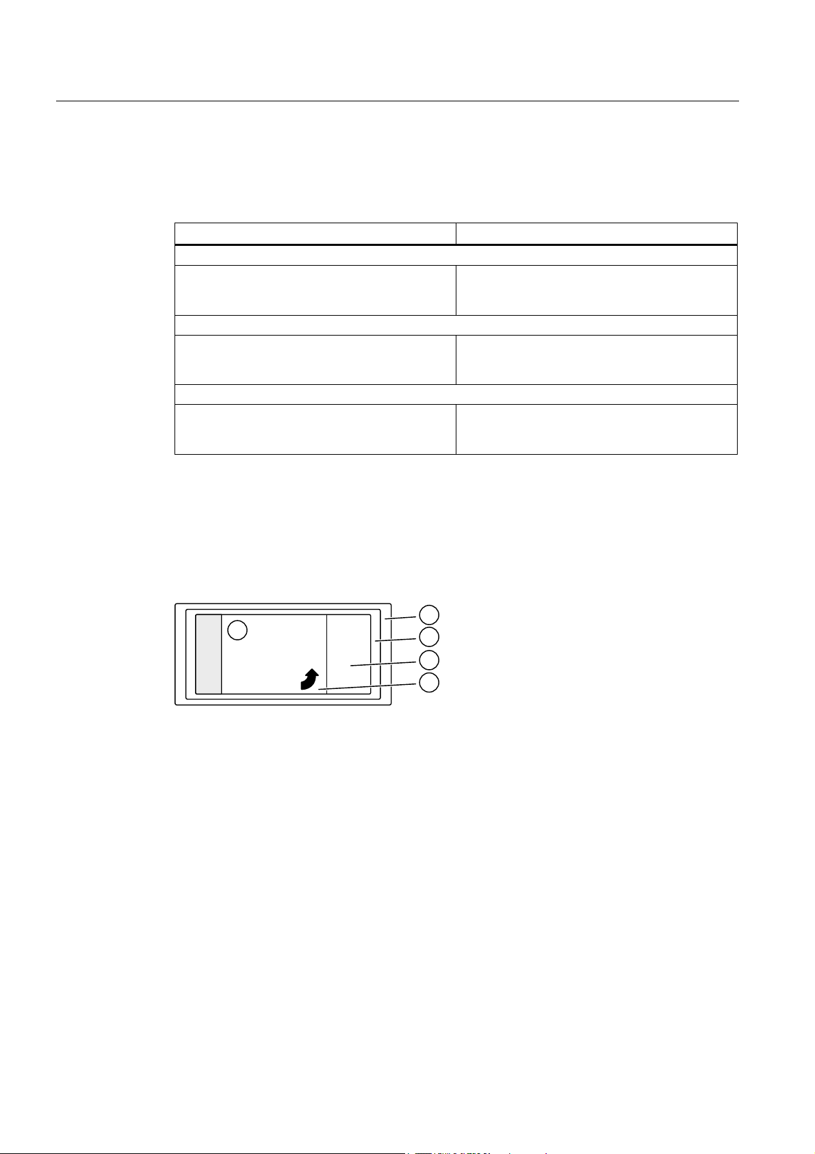
Peeling off the paint-protective film
The paint coat must have fully hardened before the paint-protective film is peeled off (be at
least "touch-proof").
① Company logo
② Masking film
③ Rating plate
④ Paint-protective film
⑤ Peeling tab
Figure 2-1 Rating plate with paint-protective film
Procedure
1. Pull the peeling tab
2. Carefully peel the paint-protective film
the plate).
⑤ up.
④ off diagonally from one corner (not parallel to
3. Blow any paint fragments away or wipe them off with a clean cloth.
You have now removed the paint-protective film.
BA 2030
18 Operating Instructions, 06/12, 70000004040207
Page 21

Incoming goods, transport, and storage
3.1 Incoming goods
NOTICE
Make sure that damaged gearboxes or geared motors are not put into operation.
Note
Do not open or damage parts of the packaging that preserve the product.
Note
Check that the technical specifications are in accordance with the purchase order.
Inspect the delivery immediately on arrival for completeness and any transport damage.
Notify the freight company of any damage caused during transport immediately (this is the
only way to have damage rectified free of charge). Siemens AG will not accept any claims
relating to items missing from the delivery and which are submitted at a later date.
3
The gearbox or geared motor is delivered in a fully assembled condition. Additional items
may be delivered packaged separately.
The products supplied are listed in the dispatch papers.
BA 2030
Operating Instructions, 06/12, 70000004040207
19
Page 22

Incoming goods, transport, and storage
3.2 Transport
3.2 Transport
3.2.1 General information on transport
NOTICE
The use of force will damage the gearbox or geared motor.
Transport the gearbox or geared motor carefully. Avoid knocks.
Before putting the drive into operation, remove any transport fixtures and keep them safe or
render them ineffective. You can then use them again for transporting further items or you
can apply them again.
Different forms of packaging may be used, depending on the size of the gearbox or geared
motor and the method of transport. Notwithstanding contractual agreements to the contrary,
the seaworthy packaging complies with HPE Packaging Guidelines (Bundesverband
Holzpackmittel Paletten Exportverpackungen e.V., the German Federal Association for
wooden packaging, pallets, and export packaging).
Note the symbols which appear on the packaging. These have the following meanings:
This way up
Center of gravity
Fragile
Do not use hand hook
Keep dry
Attach here
Keep cool
BA 2030
20 Operating Instructions, 06/12, 70000004040207
Page 23

Incoming goods, transport, and storage
3.2 Transport
3.2.2 Fastening for suspended transport
WARNING
Gearboxes or geared motors may come loose and fall down during transport if not secured
sufficiently.
Use only the transport eye or eyebolt of the gearbox to transport the gearbox or geared
motor. This is only designed for the weight of the gearbox or geared motor, and it is not
permissible to add additional loads.
Do not use the integrally cast lifting eyes on the motor for transport because of the risk of
breaking.
If necessary, use additional, suitable lifting accessories for transport or during installation.
When attaching by a number of chains and ropes just two strands must be sufficient to bear
the entire load. Secure lifting accessories against slipping.
CAUTION
Do not rig eyebolts to the front threads at the shaft ends for transportation purposes.
Table 3- 1 Maximum load of the eyebolt on the gearbox
m d
[kg] [mm]
M8 140 36 M20 1 200 72
M10 230 45 M24 1 800 90
M12 340 54 M30 3 200 108
M16 700 63
m d
3
Thread size
[kg] [mm]
Thread size
3
The eyebolt corresponds to DIN 580.
BA 2030
Operating Instructions, 06/12, 70000004040207
21
Page 24

Incoming goods, transport, and storage
3.3 Storage
3.3 Storage
3.3.1 General information for storage
WARNING
Do not stack gearboxes or geared motors one on top of another.
NOTICE
Mechanical damage (scratches), chemical damage (acids, alkalis) and thermal damage
(sparks, welding beads, heat) cause corrosion which may render the external protective
coating ineffective.
Do not damage the paint finish.
Note
Notwithstanding contractual agreements to the contrary, the guarantee period for the
standard preservative lasts 6 months from the date of delivery.
In the case of storage in transit over 6 months, special arrangements must be made for
preservation. Please contact Technical Support.
Store the gearbox or geared motor in dry, dust-free rooms that are maintained at a constant
temperature.
The storage location must be vibration- and shock-free.
The free shaft ends, sealing elements and flange surfaces must have a protective coating.
3.3.2 Storage up to 6 months
The gearbox or geared motor must be covered and stored in its position of use on a
horizontal wooden support in a dry place not subject to significant temperature fluctuations.
BA 2030
22 Operating Instructions, 06/12, 70000004040207
Page 25

Incoming goods, transport, and storage
3.3 Storage
3.3.3 Storage up to 36 months with long-term preservation (optional)
3.3.3.1 Notes for storage up to 36 months
Store the gearbox or geared motor in dry, dust-free rooms that are maintained at a constant
temperature. Special packing is then not necessary.
Otherwise, the gearbox or geared motor must be packed in plastic film or packed in airtight
sealed film and water absorbing agents. Cover them to provide protection against heat,
direct sunlight and rain.
The permissible ambient temperature range is -25 °C to +50 °C.
The life of the corrosion protection is 36 months from delivery.
3.3.3.2 Gearbox filled with operating oil and anti-corrosive agent
NOTICE
Check the oil level before commissioning.
Observe the information and procedures in Section Checking the oil level (Page 58).
The gearbox is filled with oil corresponding to the mounting position so that it is ready for
operation, and is sealed airtight using a screw plug or with a pressure breather valve with
transport fixture.
For storage up to 36 months, a VCI anti-corrosion agent (Volatile Corrosion Inhibitor) is
added.
3.3.3.3 Gearbox completely filled with oil
NOTICE
The gearbox is completely filled with operating oil.
Check the oil level before commissioning.
Observe the information and procedures in Section Checking the oil level (Page 58).
When using biologically degradable oils or oils for the foodstuff area, the gearboxes are
completely filled with operating oil and sealed airtight using a screw plug or with a pressure
breather valve with transport fixture.
Do not lower the oil level during short-time commissioning for 10 minutes in no-load
operation.
BA 2030
Operating Instructions, 06/12, 70000004040207
23
Page 26

Incoming goods, transport, and storage
3.3 Storage
BA 2030
24 Operating Instructions, 06/12, 70000004040207
Page 27

Installation
4.1 Unpacking
4.2 General information on installation
NOTICE
Make sure that damaged gearboxes or geared motors are not put into operation.
Check the gearbox or geared motor for completeness and for damage. Report any missing
parts or damage immediately.
Remove packaging and transport fixtures and dispose of them properly.
WARNING
The entire system must be load-free so that there is no danger during this work.
NOTICE
Irreparable damage to toothed components and bearings due to welding.
4
Do not carry out any welding work on the gearbox. The gearbox must not be used as a
grounding point for welding operations.
BA 2030
Operating Instructions, 06/12, 70000004040207
NOTICE
Overheating of the gearbox due to exposure to direct sunlight.
Provide suitable protective equipment such as covers or roofs. Prevent heat accumulation.
25
Page 28

Installation
4.2 General information on installation
NOTICE
Malfunction resulting from foreign objects.
The operator must ensure that no foreign objects impair the function of the gearbox.
NOTICE
Exceeding the permissible oil sump temperature due to incorrect settings of temperature
monitoring equipment.
A warning must be given when the maximum permissible oil sump temperature is reached.
The geared motor must be switched off when the maximum permissible oil sump
temperature is exceeded. This switching off can cause plant shutdown.
Note
Use headless screws of strength class 8.8 or higher to fasten the gearbox.
Exercise particular care during mounting and installation. The manufacturer cannot be held
liable for damage caused by incorrect mounting and installation.
Make sure that there is sufficient space around the gearbox or geared motor for mounting,
maintenance and repair.
On geared motors with a fan, leave sufficient free space for the entry of air. Observe the
installation conditions for the geared motor.
Provide sufficient lifting gear at the start of mounting and fitting work.
Observe the mounting position specified on the rating plate. This ensures that the correct
quantity of lubricant is provided.
Use all the fastening means that have been assigned to the particular mounting position and
mounting type.
Cap screws cannot be used in some cases due to a lack of space. In such cases, please
contact Technical Support quoting the type of gearbox.
BA 2030
26 Operating Instructions, 06/12, 70000004040207
Page 29

Installation
4.3 Thread sizes and tightening torques for fastening bolts
4.3 Thread sizes and tightening torques for fastening bolts
The general tolerance for the tightening torque in Nm is 10 %. The friction coefficient is
0.14 μ.
Table 4- 1 Tightening torques for fastening bolts
Thread size
M4 3 4 5
M5 6 9 10
M6 10 15 18
M8 25 35 41
M10 50 70 85
M12 90 120 145
M16 210 295 355
M20 450 580 690
M24 750 1 000 1 200
M30 1 500 2 000 2 400
M36 2 500 3 600 4 200
Table 4- 2 Thread size of fastening bolts for gearboxes in a foot-mounted design
Thread size
M8 29, 39 29, 39 B29, B39
M10 49 B49, K39, K49
M12 49, 59, 69 69, 79 K69, K79
M16 79, 89 89 K89
Tightening torque at strength class
8.8 10.9 12.9
[Nm] [Nm] [Nm]
Helical gearbox Parallel shaft gearbox Bevel gearbox
Size Size Size
Table 4- 3 Thread size of fastening bolts for gearboxes in a flange-mounted design
Thread
size
M6 A120 19, 29, 39 29 B29
M8 A140, A160 19, 29, 39, 49, 59 29, 39 B29, B39, K39
M10 A200 39, 49, 59, 69 49 B39, B49, K49
M12 A250, A300 59, 69, 79, 89 69, 79, 89 K69, K79, K89
M16 A350 89
BA 2030
Operating Instructions, 06/12, 70000004040207
Flange
Helical gearbox Parallel shaft gearbox Bevel gearbox
Size Size Size
27
Page 30

Installation
4.4 Fastening in the case of high shock loads
4.4 Fastening in the case of high shock loads
In the case of high shock loads provide additional suitable positive fastenings such as
cylindrical taper pins or spring pins.
NOTICE
Do not use spring washers, serrated lock washers, spring or toothed lock washers, cup
washers or conical spring washers as a substitute for the above positive fastenings.
Do not subject the housing to excessive stress when tightening the fastening bolts.
4.5 Gearbox with foot mounting
NOTICE
Do not subject the gearbox to excessive stress when tightening the fastening bolts.
The foundation must be level and free from dirt.
The levelness deviation of the gearbox support must not exceed the following values:
For gearboxes up to size 89: 0.1 mm
The foundation should be designed in such a way that no resonance vibrations are created
and no vibrations are transmitted from adjacent foundations.
The foundation structure on which the gearbox is to be mounted must be torsionally rigid. It
must be dimensioned according to the weight and torque, taking into account the forces
acting on the gearbox. If the substructure is too weak, it will cause radial or axial
displacement, which cannot be measured at a standstill.
When using foundation blocks to fasten the gearbox to a concrete foundation, suitable
recesses should be made in the foundation.
Align and grout the slide rails into the foundation.
Align the gearbox carefully with the units on the input and output side. Take into account the
elastic deformation due to operating forces.
Prevent displacement from external forces due to lateral impacts.
Use stud bolts or headless screws of strength class 8.8 or higher for the mounting foot.
Observe the tightening torque.
BA 2030
28 Operating Instructions, 06/12, 70000004040207
Page 31

Installation
4.6 Gearboxes in foot or flange version
4.6 Gearboxes in foot or flange version
NOTICE
Do not subject the gearbox housing to excessive stress by adding add-on elements to the
foot or flange.
Add-on elements must not transmit forces, torques, and vibrations to the gearbox.
The gearbox must only be mounted at either the flange or the foot to transmit force and
torque in order to prevent excessive stress to the gearbox housing, see Gearbox with foot
mounting
The se
(Page 28).
cond mounting option (foot or flange) is intended for add-on elements, e.g. protection
covers with an intrinsic weight of up to max. 30 % of the weight of the gearbox.
4.7 Mounting an input or output element on the gearbox shaft
WARNING
Risk of burns due to hot parts.
Do not touch the gearbox without protection.
NOTICE
Damage to shaft sealing rings caused by solvent or benzine.
Avoid contact at all times.
NOTICE
Damage to shaft sealing rings caused by heating over 100 °C.
Protect shaft sealing rings from heating up due to radiant heat using thermal shields.
BA 2030
Operating Instructions, 06/12, 70000004040207
29
Page 32

Installation
4.7 Mounting an input or output element on the gearbox shaft
NOTICE
Alignment errors caused by excessive angle or axial displacement of the shaft ends to be
joined lead to premature wear or material damage.
Ensure precise alignment of the individual components.
NOTICE
Damage to bearings, housing, shaft, and locking rings due to improper handling.
Do not use impacts or knocks to force the input and output elements to be mounted onto
the shaft.
Note
Deburr the parts of elements to be fitted in the area of the hole or keyways.
Recommendation: 0.2 x 45°
Where couplings are to be fitted in a heated condition, observe the specific operating
instructions for the coupling. Unless otherwise specified, the heat can be applied inductively,
using a torch or in a furnace.
Use the center holes in the shaft end faces.
Use a fitting device to fit the input or output elements.
Figure 4-1 Example of a fitting device
BA 2030
30 Operating Instructions, 06/12, 70000004040207
Page 33

Installation
4.7 Mounting an input or output element on the gearbox shaft
Observe the correct mounting arrangement to minimize stress on shafts and bearings due to
lateral forces.
Correct Incorrect
))
Procedure
D
D
a Hub
F Force
Figure 4-2 Mounting arrangement for the lowest possible stress on shafts and bearings
1. Using either benzine or solvent, remove the anti-corrosion protection from the shaft ends
and flanges and remove the protective skin provided.
2. Fit the input and output elements onto the shafts and secure them if necessary.
You have now fitted the input or output element.
BA 2030
Operating Instructions, 06/12, 70000004040207
31
Page 34

Installation
4.8 Removing and installing the protection cover
4.8 Removing and installing the protection cover
The protection cover is delivered ready-fitted to the gearbox flange. The protection cover
must be removed in order to fit the output shaft.
① Bolt
② Protection cover
③ Gearbox housing
④ Flat seal
Figure 4-3 Protection cover for hollow shaft and hollow shaft with shrink disk
Procedure
1. Release the screws ① and remove the protection cover ② and the flat seal ④.
2. Fit the output shaft.
3. Using a suitable cleaning agent, clean the contact surface of the protection cover
the gearbox.
4. Ensure that the flat seal
5. Screw on the protection cover
6. Protect all remaining bare areas with a suitable permanent anti-corrosive agent.
You have now installed the protection cover for operation.
BA 2030
32 Operating Instructions, 06/12, 70000004040207
④ is correctly seated.
②.
② on
Page 35

Installation
4.9 Installing and removing the shaft-mounted gearbox
4.9 Installing and removing the shaft-mounted gearbox
4.9.1 General information on installing the shaft-mounted gearbox
NOTICE
Damage to shaft sealing rings caused by solvent or benzine.
Avoid contact at all times.
NOTICE
Misalignment of and stress on the hollow shaft can lead to excessive load and cause the
bearings to fail.
The hollow shaft must be flush with the machine shaft to avoid misalignment.
Do not subject the hollow shaft to axial and radial stress.
NOTICE
For shrink disks:
Lubricants in the area between the hollow shaft and machine shaft impair torque
transmission.
Keep the bore in the hollow shaft and the machine shaft completely grease-free.
Do not use impure solvents and soiled cleaning cloths.
Note
Coat the contact surfaces with the mounting paste supplied with the product or any suitable
lubricant to prevent frictional corrosion.
Note
Observe the permissible concentricity tolerance of the cylindrical shaft extension of the
machine shaft to the housing axle according to DIN 42955.
BA 2030
Operating Instructions, 06/12, 70000004040207
33
Page 36

Installation
4.9 Installing and removing the shaft-mounted gearbox
4.9.2 Mounting and removing the hollow shaft with feather key
4.9.2.1 Mounting the hollow shaft with parallel key
* Not included in scope of supply
① Machine shaft
② Hollow shaft
③ Hexagon nut
④ Threaded spindle
⑤ Disk
⑥ Locking ring
⑦ Parallel key
⑧ Mounting paste
Procedure
Figure 4-4 Mounting the hollow shaft with parallel key
Instead of the nut and threaded spindle shown in the diagram, other types of equipment such
as hydraulic lifting equipment may be used.
1. Using benzine or a solvent, remove the anti-corrosion protection from the shaft ends and
flanges.
2. Check the seats or edges of the hollow and machine shafts for damage. Please contact
Technical Support if you notice any damage.
3. Evenly apply the mounting paste
4. Fit the gearbox using the disk
the hollow shaft
5. Replace the nut
specified torque.
You have now mounted the hollow shaft.
Table 4- 4 Tightening torque for setscrews
Thread size M5 M6 M8 M10 M12 M16 M20 M24 M30
Tightening torque [Nm] 5 8 8 14 24 60 120 200 400
②.
③ and threaded spindle ④ with a setscrew and tighten them to the
⑧ to the machine shaft ①.
⑤, threaded spindle ④ and nut ③. Support is provided by
BA 2030
34 Operating Instructions, 06/12, 70000004040207
Page 37

Installation
4.9 Installing and removing the shaft-mounted gearbox
4.9.2.2 Removing the hollow shaft with parallel key
NOTICE
Before driving out the machine shaft, fasten a suitably dimensioned means of absorbing the
load at the gearbox.
Slightly pretension the pulling equipment so that the gearbox does not drop onto it when the
insert shaft is released.
NOTICE
It is essential to prevent misalignment when removing the unit.
Note
If frictional corrosion has occurred on the seat surfaces, use rust solvent to facilitate the
removal of the gearbox. Allow an adequately long time for the rust solvent to take effect.
① Disk
② Threaded block
③ Parallel key
④ Hexagon nut
⑤ Threaded spindle
Figure 4-5 Removing the hollow shaft with parallel key
Items ① to ⑤ are not included in the scope of delivery.
Procedure
1. Remove the axial locking element from the hollow shaft.
2. Drive out the machine shaft using the disk
threaded spindle
You have now removed the hollow shaft with parallel key.
BA 2030
Operating Instructions, 06/12, 70000004040207
①, threaded block ②, parallel key ③,
⑤, and hexagon nuts ④.
35
Page 38

Installation
4.9 Installing and removing the shaft-mounted gearbox
Design suggestion for threaded block and disk
X
W
G
V
E
G
E
E
G
b10 b11 b12 d10 d11 t
s11
[mm] [mm] [mm] [mm] [mm]
u Size
max
[mm] [mm]
19.9 10 M6 22.5 6 29 3 15 10
24.9 14 M8 28 8
39
- - 14 M8 28
6
15 10
29.9 18 M10
33
38 10
34.9 24 10 49 6 15 5
M12 43
39.9 28
39.9 28 12 69 6 20 9
M16 48.5
44.9 33
79 6 20 9 39.9 28 M16 48.5 12
49.9 36 14 89 7 20 10
M16 64
59.9 45
8
12
14
18
BA 2030
36 Operating Instructions, 06/12, 70000004040207
Page 39

Installation
4.9 Installing and removing the shaft-mounted gearbox
4.9.3 Mounting the hollow shaft with shrink disk
4.9.3.1 Mounting the hollow shaft with shrink disk
D
E
a Greased
b Absolutely grease-free
* Not included in scope of supply
① Machine shaft
② Hollow shaft
③ Hexagon nut
④ Threaded spindle
⑤ Disk
⑧ Bronze bushing
Figure 4-6 Mounting the hollow shaft with shrink disk
E
Instead of the nut and threaded spindle shown in the diagram, other types of equipment such
as hydraulic lifting equipment may be used.
Procedure
1. Using benzine or a solvent, remove the anti-corrosion protection from the shaft ends and
flanges.
2. Check the seats or edges of the hollow and machine shafts for damage. Please contact
Technical Support if you notice any damage.
3. Fit the gearbox using the disk
the hollow shaft
4. Remove the disk
You have now mounted the hollow shaft.
BA 2030
Operating Instructions, 06/12, 70000004040207
⑤, threaded spindle ④ and nut ③. Support is provided by
②.
⑤, threaded spindle ④ and nut ③.
37
Page 40

Installation
4.9 Installing and removing the shaft-mounted gearbox
4.9.3.2 Mounting the shrink disk
WARNING
Risk of injury due to freely rotating parts.
Fit a cover cap or protection cover.
NOTICE
The shrink disk is delivered ready for installation.
Do not dismantle it before the initial fitting.
NOTICE
Lubricants in the area of the shrink disk seat impair torque transmission.
Keep the bore in the hollow shaft and the machine shaft completely grease-free.
Do not use impure solvents and soiled cleaning cloths.
NOTICE
Plastic deformation of the hollow shaft when tightening the tightening bolts before fitting the
machine shaft.
First fit machine shaft. Then tighten the tightening bolts.
NOTICE
Avoid overloading the individual bolts.
Do not exceed the maximum tightening torque for tightening bolt.
Sizes 29 - 69:
Tighten the tightening bolts
③.
Sizes 79 - 89:
What is of prime importance is that the end faces of the outer ring
① and inner ring ② are
flush with one another. If they are not flush with one another when tensioning, the tolerance
of the insert shaft must be checked.
BA 2030
38 Operating Instructions, 06/12, 70000004040207
Page 41

Installation
4.9 Installing and removing the shaft-mounted gearbox
Note
The machine shaft material must comply with the following criteria in order to safely and
reliably transfer the forces and torques.
Yield point, Re >= 360 Nm / mm
Modulus of elasticity: approx. 206 kN / mm
Note
2
-2
The hollow shaft is axially secured on the machine shaft by means of a shrink disk
connection.
Note
Apply a thin layer of grease to the shrink disk seat on the hollow shaft.
Note
Coat with a suitable lubricant to prevent frictional corrosion of the contact surface on the
customer's machine shaft in the vicinity of the bush.
Sizes 29 - 69 Sizes 79 - 89
DD DDD
E
a Greased
b Absolutely grease-free
E
BA 2030
Operating Instructions, 06/12, 70000004040207
39
Page 42

Installation
4.9 Installing and removing the shaft-mounted gearbox
① Outer ring
② Inner ring
③ Tightening bolt
④ Hollow shaft
⑤ Machine shaft
Figure 4-7 Mounting the shrink disk
Procedure
1. Locate the shrink disk on the hollow shaft:
3-section (sizes 29-69) up to the endstop.
2-section (sizes 79-89) flush with the shaft end.
2. To start, tighten the tightening bolts
clamping flanges are coplanar with one another.
3. To do this, turn each of the tightening bolts
opposite) using a torque wrench, repeating this procedure several times, until the screw
tightening torque is reached.
4. Attach the rubber cover or protection cover included in the scope of delivery,
see Removing and installing the prote
You have now installed the shrink disk.
Table 4- 5 Tightening torque for tightening bolt
Gearbox size Thread size Strength class
29 M5 8.8 5
39 - 69 M6 8.8 12
79 - 89 M10 12.9 35
③ by hand, and then align the shrink disk so that the
③ equally by 1/6 revolution (not diagonally
ction cover (Page 32).
Tightening torque
[Nm]
BA 2030
40 Operating Instructions, 06/12, 70000004040207
Page 43

Installation
4.9 Installing and removing the shaft-mounted gearbox
4.9.3.3 Pulling off the shrink disk
Procedure
1. Going around several times, release the tightening bolts ③ one after the other by a
¼ turn each time using a wrench. Do not completely remove the screws.
2. Pull the shrink disk off the hollow shaft.
Sizes 79 - 89:
If the outer ring does not come away from the inner ring, remove some of the tightening bolts
and insert them into neighboring forcing threads.
You will then be able to release the rings without difficulty.
4.9.3.4 Cleaning and lubricating shrink disks
Soiled shrink disks must be cleaned and regreased prior to fitting.
Shrink disks that have been released need not be disassembled and regreased before being
retensioned.
Procedure
1. Only grease the inner friction surfaces of the shrink disks. To do this, use a solid lubricant
with a friction coefficient of μ = 0.04.
2. Use a paste containing MoS
to grease the bolts, applying the paste to the thread and
2
underneath the head.
The shrink disk is now ready for fitting.
Table 4- 6 Lubricants for shrink disks
Lubricant Sold as Manufacturer
Molykote 321 R (lubricant paint)
Molykote spray (powder spray)
Molykote G Rapid Spray or paste
Molykombin UMFT 1 Spray
Unimily P5 Powder
Aemasol MO 19 P Spray or paste A. C. Matthes
Spray
DOW Corning
Klüber Lubrication
BA 2030
Operating Instructions, 06/12, 70000004040207
41
Page 44

Installation
4.9 Installing and removing the shaft-mounted gearbox
4.9.4 Mounting the hollow shaft with splines
* Not included in scope of supply
① Machine shaft
② Hollow shaft
③ Hexagon nut
④ Threaded spindle
⑤ Disk
⑥ Locking ring
⑦ Mounting paste
Procedure
Figure 4-8 Mounting the hollow shaft with splines
Instead of the nut and threaded spindle shown in the diagram, other types of equipment such
as hydraulic lifting equipment may be used.
1. Using benzine or a solvent, remove the anti-corrosion protection from the shaft ends and
flanges.
2. Check the seats or edges of the hollow and machine shafts for damage. Please contact
Technical Support if you notice any damage.
3. Evenly apply the assembly paste
4. Fit the gearbox using the disk
the hollow shaft
5. Replace the nut
specified torque.
You have now mounted the hollow shaft.
Table 4- 7 Tightening torque for setscrews
Thread size M5 M6 M8 M10 M12 M16 M20 M24 M30
Tightening torque [Nm] 5 8 8 14 24 60 120 200 400
②.
③ and threaded spindle ④ with a setscrew and tighten them to the
⑦ to the machine shaft ①.
⑤, threaded spindle ④ and nut ③. Support is provided by
BA 2030
42 Operating Instructions, 06/12, 70000004040207
Page 45

Installation
4.9 Installing and removing the shaft-mounted gearbox
4.9.5 Torque arms with shaft-mounted gearboxes
4.9.5.1 General information regarding torque arms
Torque arms can absorb the reaction torque and the weight force of the gearbox.
NOTICE
Dangerously high transient torques due to excess backlash.
Ensure that the torque arm does not result in excessive constraining forces (e.g. due to the
driven shaft running out-of-true).
NOTICE
Do not tension torque arms when mounting.
NOTICE
Worn or irreparably damaged rubber elements will not function properly.
Solvents, oils, greases, and fuels damage rubber elements. Keep them away from the
rubber elements.
BA 2030
Operating Instructions, 06/12, 70000004040207
43
Page 46

Installation
4.9 Installing and removing the shaft-mounted gearbox
4.9.5.2 Mounting torque arms on parallel shaft gearboxes
We recommend using pretensioned, damping rubber elements.
Fixing accessories such as brackets, bolts, nuts, etc., are not included in the scope of
delivery.
O[
O
G
FPLQ
\
\
Procedure
G
G
G
5=
\
5=
Figure 4-9 Mounting suggestion for torque arms on F.29 - F.89
Size
Rubber buffer
Washer
untensioned tensioned
l1 l1x d6 d1 d5 c6
[mm] [mm] [mm] [mm] [mm] [mm]
29 15 14.0 30 10.5 40 4
39 15 13.5 30 10.5 40 4
49 20 18.5 40 12.5 50 6
69 20 18.5 40 12.5 50 6
79 20 17.5 40 12.5 50 6
89 30 28 60 21 75 8
1. Use the washers according to the table above.
min
2. Use 2 nuts to secure the screw connection (lock nuts).
3. Tighten the screws until the rubber buffers are pretensioned to the dimension l1x.
You have now mounted the torque arm.
BA 2030
44 Operating Instructions, 06/12, 70000004040207
Page 47

Installation
4.9 Installing and removing the shaft-mounted gearbox
4.9.5.3 Mounting torque arms on bevel gearboxes
NOTICE
The torque arm bush must be supported by bearings on both sides.
Figure 4-10 Mounting suggestion for torque arms on bevel gearbox K
Procedure
Figure 4-11 Mounting suggestion for torque arms on bevel gearbox B
The torque arm can be mounted in various positions, depending on the hole circle pitch.
1. Clean the contact surfaces between the housing and the torque arm.
2. Tighten the screws to the specified torque.
You have now mounted the torque arm.
Table 4- 8 Tightening torque for screws of strength class 8.8 when mounting the torque arm
Thread size M8 M10 M12 M16 M20 M24 M30
Tightening torque [Nm] 25 50 90 210 450 750 1 500
BA 2030
Operating Instructions, 06/12, 70000004040207
45
Page 48

Installation
4.9 Installing and removing the shaft-mounted gearbox
BA 2030
46 Operating Instructions, 06/12, 70000004040207
Page 49

Commissioning
5.1 General information for commissioning
WARNING
Secure the drive unit to prevent it from being started up unintentionally.
Attach a warning notice to the start switch.
WARNING
Remove any oil spillage immediately with an oil-binding agent in compliance with
environmental requirements.
Checking the pressure breather valve
Check that the pressure breather valve is activated.
If the pressure breather valve has a transport fixture, then this must be removed before
commissioning.
5
Figure 5-1 Pressure breather valve with securing clip
Remove the transport fixture by pulling the securing clip ① in the direction of the arrow.
5.2 Checking the oil level prior to commissioning
Check the oil level before commissioning and top up if necessary, see Checking and
changing lubricants (Page 57).
arboxes with long-term preservation that are shipped completely filled with oil, we
For ge
recommend that for storage times exceeding 24 months, the oil is completely
replaced Checking and changing lubricants (Page 57).
BA 2030
Operating Instructions, 06/12, 70000004040207
47
Page 50

Commissioning
5.3 Mounting the oil expansion unit
5.3 Mounting the oil expansion unit
An oil expansion unit can be used depending on the power, drive speed, type of construction
and transmission ratio. This is used to equalize changes in the oil volume caused by
temperature fluctuations in operation.
The oil expansion unit is supplied as mounting set, and can either be mounted vertically on
the geared motor or at an angle.
The oil expansion unit for sizes 39 to 89 is mounted using a screw connection at the highest
hole on the gearbox housing or motor bearing shield.
Before commissioning the gearbox, replace the pressure breather valve that is already
installed by the oil expansion unit provided.
Figure 5-2 Example of an oil expansion unit
Procedure:
1. Completely unscrew the pressure breather valve with transport fixture.
2. Screw in the completely preassembled oil equalization unit.
3. Align the oil equalization unit so that it is in a vertical position.
The vent valve must be replaced every year to ensure perfect functioning. When replacing,
prevent dirt and damaging atmospheres from entering the gearbox.
BA 2030
48 Operating Instructions, 06/12, 70000004040207
Page 51

Operation
6
CAUTION
In the event of changes during operation, the drive unit must be switched off immediately.
Determine the cause of the fault using the fault table in Section Faults, causes and
reme
dies (Page 51).
dy faults or have faults remedied.
Reme
Check the gearbox during operation for:
● Excessive operating temperature
● Changes in gear noise
● Possible oil leakage at the housing and shaft seals.
BA 2030
Operating Instructions, 06/12, 70000004040207
49
Page 52

Operation
BA 2030
50 Operating Instructions, 06/12, 70000004040207
Page 53

Faults, causes and remedies
Note
Faults and malfunctions occurring during the warranty period and requiring repair work on
the gearbox must be remedied only by Technical Support. In the case of faults and
malfunctions occurring after the warranty period, the cause of which cannot be precisely
identified, we advise our customers to contact our Technical Support.
If you need the help of Technical Support, please provide the following information:
Data on the rating plate
Nature and extent of the fault
Suspected cause.
Table 7- 1 Faults, causes and remedies
Faults Causes Remedy
Unusual noises on the gearbox
Oil level too low Check the oil level, see
Foreign bodies in oil (irregular
noise)
Excessive bearing play and / or
bearing defective
Defective gearing Check the gearing and replace
Fastening bolts loose Tighten bolts / nuts; see
Excessive external load on drive
input and output
Damage in transit Check the gearbox for damage
Damage due to blockage during
commissioning
7
Checking and changing
lubricants (Page 57)
Check the oil quality, see
Checking the oil quality
(Page 59). Clean the gearbox.
Change the oil, see Checking
and changing lubricants
(Page 57)
Check bearing and replace
if necessary
if necessary
Checking tightness of fastening
bolts (Page 71)
Check load against rated data
(you might need to correct the
belt tension, for example)
in transit
Call Technical Support
BA 2030
Operating Instructions, 06/12, 70000004040207
51
Page 54

Faults, causes and remedies
Faults Causes Remedy
Unusual motor noises
Oil leak
Oil leak at the gearbox vent
Excessive bearing play and / or
bearing defective
Motor brake rubbing Check air gap and adjust
Inverter parameterization Correct parameterization
Incorrect oil level for the
mounting position being used
Overpressure due to lack of
venting
Overpressure due to soiled
venting
Shaft sealing rings defective Replace the shaft sealing rings
Cover / flange bolts loose Tighten bolts / nuts, see
Surface sealing defective
(e.g. on cover, flange)
Damage in transit (e.g. hairline
cracks)
Incorrect oil level for the
mounting position used and / or
incorrect venting position
Frequent cold starts, during
which the oil foams up
Check bearing and replace
if necessary
if necessary
Check the mounting position,
see Mounting positions
(Page 79). Check the oil level,
see Checking and changing
lubricants (Page 57)
Mount the venting as
appropriate for the mounting
position, see Mounting positions
(Page 79).
Clean the venting, see
Replacing the vent valve
(Page 69).
Checking tightness of fastening
bolts (Page 71). Continue to
monitor the gearbox
Reseal
Check the gearbox for damage
in transit
Check the venting and mounting
position, see Mounting positions
(Page 79). Check the oil level,
see Checking and changing
ants (Page 57)
lubric
Call Technical Support
BA 2030
52 Operating Instructions, 06/12, 70000004040207
Page 55

Faults, causes and remedies
Faults Causes Remedy
Gearbox overheating
Output shaft does not turn when
motor is running
Geared motor only starts with
difficulty or not at all
Motor fan cover and / or
gearbox very dirty
Incorrect oil level for the
mounting position being used
Incorrect oil being used
(e.g. incorrect viscosity)
Oil is out of date Check date of last oil change
Excessive bearing play and / or
bearing defective
Force flow interrupted by
breakage in gearbox
Incorrect oil level for the
mounting position being used
Incorrect oil being used
(e.g. incorrect viscosity)
Excessive external load on drive
input and output
Motor brake is not released Check circuit / connection of
Geared motor runs against
backstop
Clean the fan cover and surface
of the geared motor, see
Cleaning the gearbox
(Page 70)
Check the mounting position,
see Mounting positions
(Page 79). Check the oil level,
see Checking and changing
lubricants (Page 57)
Check the oil in the gearbox,
see Checking the oil quality
(Page 59).
and change oil if necessary, see
Checking and changing
lubricants (Page 57)
Check bearing and replace
if necessary
Call Technical Support
Check the mounting position,
see Mounting positions
(Page 79). Check the oil level,
see Checking and changing
lubricants (Page 57)
Check the oil in the gearbox,
see Checking the oil quality
(Page 59).
Check load against rated data
(you might need to correct the
belt tension, for example)
brake. Check brake for wear
and readjust if necessary
Change direction of motor or
backstop rotation
BA 2030
Operating Instructions, 06/12, 70000004040207
53
Page 56

Faults, causes and remedies
Faults Causes Remedy
Excessive play at drive input
and output
Drop in speed / torque Belt tension too low (in case of
Flexible elements worn (e.g. on
couplings)
Positive connection disrupted by
overload
belt drive)
Replace flexible elements.
Call Technical Support
Check belt tension and replace
belt if necessary
BA 2030
54 Operating Instructions, 06/12, 70000004040207
Page 57

Service and maintenance
8.1 General notes about maintenance work
WARNING
Secure the drive unit to prevent it from being started up unintentionally.
Attach a warning notice to the start switch.
NOTICE
Service and maintenance must only be carried out by properly trained and authorized
personnel. Only original parts supplied by Siemens AG can be used for servicing and
maintenance.
All inspection, maintenance, and repair work must be carried out with care by trained
personnel only. Observe the information in Section General information and safety notes
(Page 7).
8
Table 8- 1 Maintenance measures
Measure Time interval Description of work
Monitor and check the geared
motor for unusual noises,
vibrations, and changes
Check housing temperature After 3 hours, on the first day,
Check the oil level After the first day, and then
Check the oil level sensor Regularly and after oil changes See Checking the oil level
Check the oil quality Every 6 months See Checking the oil quality
Daily; if possible, more
frequently during operation
thereafter monthly
every 3 000 operating hours, or
at the latest after 6 months
See Operation (Page 49)
See Checking and changing
lubricants (Page 57)
sensor (optional) (Page 70)
(Page 59)
BA 2030
Operating Instructions, 06/12, 70000004040207
55
Page 58

Service and maintenance
8.1 General notes about maintenance work
Measure Time interval Description of work
First oil change after
commissioning
Subsequent oil changes Every 2 years or
Check gearbox for leaks After the first day, thereafter
When required, replace the
gearbox breather valve
Clean the gearbox Depending on degree of soiling,
Carry out a complete inspection
of the geared motor
Check that fastening bolts on
gearboxes and built-on
accessories are securely
tightened. Check that covers
and plugs are securely
fastened.
Change the roller bearing
grease
Check rubber buffers on torque
arms
1) When using synthetic oils, the intervals can be doubled. The data specified is valid for an oil
temperature of +80 °C. See the figure titled "Guide values for oil change intervals" for oil change
intervals for other temperatures.
After approximately
10 000 operating hours or at the
latest after 2 years
10 000 operating hours 1)
monthly
Once a year See Replacing the vent valve
at least every 6 months
Every 12 months See Inspecting the gearbox or
After 3 h, and then every 2
years
When the oil is changed See Changing the roller bearing
Every 6 months See Torque arms with shaft-
See Checking and changing
lubricants (Page 57)
See Checking the gearbox for
leaks (Page 69)
(Page 69)
See Cleaning the gearbox
(Page 70)
geared motor (Page 71)
See Checking tightness of
fastening bolts (Page 71)
grease (Page 64)
mounted gearboxes (Page 43)
BA 2030
56 Operating Instructions, 06/12, 70000004040207
Page 59

Service and maintenance
8.2 Checking and changing lubricants
8.2 Checking and changing lubricants
8.2.1 General safety notes for checking and changing lubricants
WARNING
Danger of scalding from the hot oil emerging from the unit.
Before starting any work wait until the oil has cooled down to below +30 °C.
WARNING
Remove any oil spillage immediately with an oil-binding agent in compliance with
environmental requirements.
NOTICE
Incorrect oil quantities can damage the gearbox.
The oil quantity and the position of the sealing elements are determined by the mounting
position.
After removing the oil level screw, up to and including gearbox size 89, the oil level may not
be more than 3 mm below the recommended filling level.
NOTICE
Dirt and damaging atmospheres can penetrate into the gearbox through open holes used to
check or drain the oil.
Immediately close the gearbox after checking the oil level or changing the oil.
Note
For data such as type of oil, oil viscosity, and oil quantity required, refer to the rating plate.
For oil compatibility see Recommended lubricants (Page 67).
Note
Gearbox sizes 19 and 29 are lubricated for life:
No oil changes are required.
BA 2030
Operating Instructions, 06/12, 70000004040207
57
Page 60

Service and maintenance
8.2 Checking and changing lubricants
8.2.2 Checking the oil level
Procedure
NOTICE
The volume of gearbox oils changes with temperature.
If the temperature rises, the volume increases. Where temperature differences and filling
quantities are significant, the increase can amount to several liters.
The oil level must therefore be checked while still slightly warm, approximately 30 minutes
after switching off the drive unit.
Figure 8-1 Oil level in the gearbox housing
1. Switch off the power supply to the drive unit.
2. Unscrew the oil level screw, see Mounting positions (Page 79).
3. Check the oil level
4. Top up the oil level
①.
① if necessary, and check it again.
5. Check the condition of the sealing ring on the sealing element and if the sealing ring is
damaged, replace the sealing element with a new one.
6. After checking the oil level, immediately seal the gearbox using the sealing element.
You have now checked the oil level in the gearbox housing.
BA 2030
58 Operating Instructions, 06/12, 70000004040207
Page 61

Service and maintenance
8.2 Checking and changing lubricants
8.2.3 Checking the oil level using the oil sight glass (optional)
If there is an oil sight glass to check the oil level ①, the oil must be visible in the center of
the sight glass when the oil is cool. When the oil is hot, the oil level
the sight glass. The oil level
Figure 8-2 Oil level in the oil sight glass
Top up the oil level ① if necessary, and check it again.
① of cold oil is below the center of the sight glass.
① is above the center of
8.2.4 Checking the oil quality
Signs of changes in the oil can be seen with the naked eye. Fresh oil is clear to the eye, and
has a typical smell and a specific product color. Clouding or a flocculent appearance
indicates water and / or contamination. A dark or black color indicates residue, serious
thermal decomposition or contamination.
Procedure
Observe the symbols in the diagrams of the mounting positions, see Mounting positions
(Page 79):
Venting Oil level
1. Allow the geared motor to run for a short time. Wear and contaminant particles are visible
in the oil shortly after shutting down.
2. Switch off the power supply to the drive unit.
3. Unscrew the sealing element at one of the points marked with the symbols listed above.
4. Remove some oil, using a suction pump and a flexible hose, for example.
5. Check the condition of the sealing ring on the sealing element and replace the sealing
ring if necessary.
6. Seal the gearbox with the sealing element.
7. Check the oil for abnormalities. If you detect any abnormalities, change the oil
immediately.
You have now checked the oil quality.
BA 2030
Operating Instructions, 06/12, 70000004040207
59
Page 62

Service and maintenance
8.2 Checking and changing lubricants
8.2.5 Changing the oil
8.2.5.1 General safety notes for changing the oil
NOTICE
An impermissible mixture of oils will lead to clouding, depositing, foam formation, changes
to the viscosity or reduced protection against corrosion and wear.
When changing oil of the same type, the residual volume of oil in the gearbox should be
kept as low as possible. Generally speaking, a small residual volume will cause no
particular problems.
Gear oils of different types and by different manufacturers must not be mixed. Have the
manufacturer confirm that the new oil is compatible with the remaining volume of used oil.
If changing very different types of oil or oils with very different additives, always flush out
the gearbox with the new oil. When changing from mineral oil to polyglycol oil (PG) or vice
versa, it is vital to flush the gearbox twice. All traces of old oil must be completely removed
from the gearbox.
NOTICE
Gearbox oils must never be mixed with other substances. Do not flush with paraffin or other
solvents, as traces of these substances will always be left behind inside the gearbox.
Note
The oil must be warm. If it is too cold, it will flow too sluggishly to drain properly. If necessary,
run the gearbox for 15 to 30 minutes to warm it up.
BA 2030
60 Operating Instructions, 06/12, 70000004040207
Page 63

Service and maintenance
8.2 Checking and changing lubricants
8.2.5.2 Draining the oil
Observe the symbols in the diagrams of the mounting positions, see Mounting positions
(Page 79):
Venting Oil level Oil drain
Procedure
1. Switch off the power supply to the drive unit.
2. Unscrew the vent plug.
3. Unscrew the oil level screw.
4. Place a suitable and sufficiently large receptacle underneath the oil drain plug.
5. Unscrew the oil drain plug and drain all the oil into the receptacle.
6. Check the condition of the sealing ring on the sealing element and if the sealing ring is
damaged, replace the sealing element with a new one.
7. After draining the oil, immediately seal the gearbox using the sealing element.
You have now drained the oil from the gearbox.
BA 2030
Operating Instructions, 06/12, 70000004040207
61
Page 64

Service and maintenance
8.2 Checking and changing lubricants
8.2.5.3 Flushing the gearbox when changing between incompatible oils
NOTICE
Polyglycol oil has a higher density than mineral oil. Therefore, it sinks down towards the oil
drain and the mineral oil floats on top.
This makes the required complete draining of mineral oil from the gearbox extremely
difficult.
NOTICE
A flushing process is required with biodegradable and physiologically safe oils.
Note
After the second flush, we recommend that an an appropriate analysis institute checks the
quality of the flushed fluid.
Observe the symbols in the diagrams of the mounting positions, see Mounting positions
(Page 79):
Venting Oil drain
Procedure
1. After the oil has been drained, wipe the gearbox clean of any remaining mineral oil using
a cloth.
2. Unscrew the vent plug.
3. Fill the gearbox with a flushing oil, using a filter (filter mesh max. 25 μm). For the flushing
oil, use either the new oil or one that is compatible with the new oil and is less expensive.
4. Operate the gearbox for 15 to 30 minutes under a low load.
5. Place a suitable and sufficiently large receptacle underneath the oil drain plug.
6. Unscrew the oil drain plug and drain all the oil into the receptacle.
7. After flushing, immediately seal the gearbox using the sealing element.
8. Repeat this step for the second flushing.
You have now flushed the gearbox twice and can pour in the new oil.
BA 2030
62 Operating Instructions, 06/12, 70000004040207
Page 65

Service and maintenance
8.2 Checking and changing lubricants
8.2.5.4 Filling in oil
Procedure
NOTICE
When adding oil, use the same oil type and viscosity. If changing mutually incompatible
oils, flushing cycles are required, see Flushing the gearbox when
changing between
incompatible oils (Page 62).
Observe the symbols in the type of construction diagrams, see Mounting positions
(Page 79):
Venting
1. Unscrew the vent plug.
2. Fill the gearbox with fresh oil, using a filter (filter mesh, max. 25 μm).
3. Check the oil level.
4. Top up the oil level if necessary and check it again.
5. Check the condition of the sealing ring on the sealing element and if the sealing ring is
damaged, replace the sealing element with a new one.
6. After filling the oil, immediately seal the gearbox using the sealing element.
You have now filled up the gearbox with oil.
BA 2030
Operating Instructions, 06/12, 70000004040207
63
Page 66

Service and maintenance
8.2 Checking and changing lubricants
8.2.6 Topping up with oil
You may need to top the gearbox up with oil if the gearbox mounting position changes or if
oil is lost due to a leak. If you notice oil escaping, locate the leak and seal the affected area.
Top up and check the oil level.
At the time of going to print, the following types of oil are being used when the gearbox is
filled for the first time:
CLP ISO VG220: ARAL Degol BG 220
CLP ISO PG VG220: Castrol Tribol 1300 / 220
CLP ISO PG VG460: Castrol Tribol 1300 / 460
CLP ISO PAO VG68: Addinol Eco Gear 68S-T
CLP ISO PAO VG220: Addinol Eco Gear 220S
CLP ISO E VG220: Fuchs Plantogear Bio 220S
CLP ISO H1 VG460: Klüber Klüberoil 4 UH1 460 N
If, following agreement, gearboxes are filled at the factory with special lubricants for the
special applications referred to above, this is shown on the rating plate.
8.2.7 Changing the roller bearing grease
The roller bearings are lubricated in the factory with the greases listed in the table.
When changing the oil, the specified grease quantity of grease-lubricated bearings should
also be replaced.
Clean the bearing before filling it with fresh lubricant.
In the case of bearings on the output shaft or intermediate shafts, the grease quantity must
fill 2/3, and in the case of bearings on the input side, 1/3 of the space between the rolling
elements.
Table 8- 2 Roller bearing and shaft sealing ring grease
Fields of application Ambient temperature Manufacturer Type
Standard -40 °C to +80 °C Klüber Petamo GHY 133 N
Foodstuff-compatible
for the food industry
Biologically degradable,
for agriculture, forestry
and water industries
-30 °C to +40 °C Castrol Obeen UF F2 NSF H1
-35 °C to +40 °C BP Biogrease EP 2
BA 2030
64 Operating Instructions, 06/12, 70000004040207
Page 67

Service and maintenance
8.2 Checking and changing lubricants
8.2.8 Service life of the lubricants
Note
In case of ambient conditions deviating from normal conditions, e.g. high ambient
temperatures, high relative humidity, aggressive ambient media, the intervals between
changes should be shorter. In such cases please contact Technical Support for assistance in
determining the individual lubricant change intervals.
Note
Oil sump temperatures above +80 °C can reduce service life. In this context, the rule is that
increasing the temperature by 10 K will approximately halve the service life, as illustrated in
the figure titled "Guide values for oil change intervals".
For a +80 °C oil sump temperature, the following service life can be expected when
observing the properties specified by Siemens AG:
Table 8- 3 Service life of the oils
Type of oil Service life
Mineral oil
Biodegradable oil
Physiologically safe oil according to USDA-H1/-H2
Synthetic oil 20 000 operating hours or 4 years
10 000 operating hours or 2 years
BA 2030
Operating Instructions, 06/12, 70000004040207
65
Page 68

Service and maintenance
8.2 Checking and changing lubricants
7>r&@
,>K@
① Mineral oil
② Synthetic oil
T Oil-bath steady-state temperature [°C]
I Oil change interval in operating hours [h]
Figure 8-3 Guide values for oil change intervals
Grease service life of roller bearing greases
Roller bearings and the clearance in front are filled with sufficient grease.
Under approved operating conditions and ambient temperatures, no regreasing is required.
We recommend that the grease in the bearings is also renewed when the oil or shaft sealing
rings are replaced.
BA 2030
66 Operating Instructions, 06/12, 70000004040207
Page 69

Service and maintenance
8.2 Checking and changing lubricants
8.2.9 Recommended lubricants
DANGER
The lubricants used have not been approved to USDA -H1/-H2 (United States Department
of Agriculture). They are not or only conditionally approved for use in the foodstuff or
pharmaceutical industry.
For applications in the food or pharmaceutical industry, only use the lubricants with USDA H1/-H2 approval listed in the released and recommended gearbox lubricants T 7300.
NOTICE
For applications outside the temperature range specified in the BA 7300 Operating
Instructions, please contact Technical Support for advice on which oil to use.
If the housing temperature exceeds a value of +80 °C, please contact Technical Support.
NOTICE
As standard, the lubricants and shaft seals are harmonized and coordinated with one
another corresponding to the prevailing operating conditions. When the operating
conditions change, the oil type changes or new shaft seals are inserted, please contact
Technical Support.
Note
The lubricants used are not at all or only conditionally biodegradable. If biologically
degradable lubricants are required, then only use the lubricants with the appropriate
classifications, listed in the released and recommended gearbox lubricants T 7300.
Note
These recommendations are not a guarantee of the quality of the lubricant provided by your
supplier. All lubricant manufacturers are responsible for the quality of their own products.
BA 2030
Operating Instructions, 06/12, 70000004040207
67
Page 70

Service and maintenance
8.2 Checking and changing lubricants
The oil selected for use in the gearbox must be of the viscosity stated on the rating plate
(ISO VG class). The viscosity class indicated applies for the contractually agreed operating
conditions.
In the case of different operating conditions, please contact Technical Support.
If, following agreement, gearboxes are filled at the factory with special lubricants for the
special applications referred to above, this is shown on the rating plate.
The quality of the oil used must comply with the requirements laid down in the BA 7300
Operating Instructions; otherwise, the Siemens warranty is null and void. We urgently
recommend using one of the oils listed in the released and recommended lubricants T 7300
(http://support.automation.siemens.
com/WW/view/en/44231658), which were appropriately
tested and comply with the requirements.
The oils listed there are subject to continuous testing. Under certain circumstances, it is
therefore possible that the oils recommended there are at a later point in time removed or
replaced by oils that have been further developed.
We recommend that you regularly check as to whether the selected lubricating oil is still
recommended by Siemens. Otherwise, a different oil type should be selected.
BA 2030
68 Operating Instructions, 06/12, 70000004040207
 Loading...