

Siemens 7sg15 microtapp Operation Manual
Answers for energy
7SG15 MicroTAPP
Automatic Voltage Control
Reyrolle
Protection
Devices

Contents
Technical Manual Chapters
1. Description of operation
2. Performance Specification
3. Relay Settings
4. Communications
5. Application Guide
6. Installation
7. Commissioning
8. Maintenance
7SG15 MicroTAPP Contents
The copyright and other intellectual property ri ghts in this document, and in any model or article produced from it (and
including any registe red or unregistered design rights) are the property of Siemens Protection Devices Limited. No
part of this document shall be reproduced or modified or stored in another form, in any data retrieval system, without
the permission of Siemens Protection Devices Limited, nor shall any model or article be reproduced from this
document unless Siemens Prot ection Devices Limited consent.
While the information and guidance given in this document is believed to be correct, no liability shall be accepted for
any loss or damage caused by any error or omission, whether such error or omission is the result of negligence or
any other cause. Any and all s uch liability is disclaimed.
©2012 Siemens Protection Devices Limited

7SG15 MicroTAPP Description of Operation
The copyright and other intellectual property rights in this document, and in any model or article produced from it
(and including any registered or unregistered design rights) are the property of Siemens Protection Devices
Limited. No part of this document shall be reproduced or modified or stored in another form, in any data retrieval
system, without the permission of Siemens Protection Devices Limited, nor shall any model or article be
reproduced from this document unless Siemens Protection Devices Limited consent.
While the information and guidance given in this document is believed to be correct, no liability shall be accepted
for any loss or damage caused by any error or omission, whether such error or omission is the result of
negligence or any other cause. Any and all such liability is disclaimed.
©2013 Siemens Protection Devices Limited
7SG15 MicroTAPP
Automatic Voltage Control
Document Release History
This document is issue 2013/06. The list of revisions up to and including this issue is:
Pre release
2013/06 Release of software revisions R10 and R19
2012/05 Release of software revisions R9 and R18
2010/02 Document reformat due to rebrand
Software Revision History

7SG15 MicroTAPP Description of Operation
©2013 Siemens Protection Devices Limited Chapter 1 Page 2 of 38
Contents
1
Introduction....................................................................................................................................... 4
2 Power system requirements............................................................................................................. 4
3 MicroTAPP Functionality.................................................................................................................. 4
3.1 Inputs.......................................................................................................................................... 4
3.1.1 Voltage Measurement........................................................................................................ 5
3.1.2 Current Measurement........................................................................................................ 5
3.1.3 Status................................................................................................................................. 5
3.2 Outputs ....................................................................................................................................... 5
4 Description of operation ................................................................................................................... 6
4.1 General....................................................................................................................................... 6
4.2 Transformers in Parallel ............................................................................................................. 8
4.2.1 Circulating Current Control ................................................................................................ 8
4.2.2 Negative Reactance circulating current control – TAPP ................................................. 10
4.2.3 Master/Follower control ................................................................................................... 11
4.3 Load Drop Compensation ........................................................................................................ 11
4.4 MT102 Advanced Features ...................................................................................................... 11
4.4.1 Description of Operation.................................................................................................. 11
4.4.2 Location of tap-changer, HV or LV side........................................................................... 12
4.4.3 Change in voltage per tap ............................................................................................... 12
4.4.4 Single phase or 3 phase units ......................................................................................... 13
4.4.5 Direction of tap-changer for voltage increase.................................................................. 13
4.4.6 Transformer impedance .................................................................................................. 13
4.4.7 Nominal voltage or winding load drop compensated target settings............................... 13
4.4.8 Dead-Reckoning Block .................................................................................................... 13
4.4 MicroTAPP–MicroTAPP communications................................................................................ 13
4.5 Low Frequency Voltage Reduction .......................................................................................... 13
4.6 Transformer Switch out ............................................................................................................ 13
4.7 Transformer Switch in .............................................................................................................. 14
4.8 Relay Settings .......................................................................................................................... 14
4.8.1 Basic Set-point.................................................................................................................14
4.8.2 Normal voltage deadband ............................................................................................... 14
4.8.3 Load Drop Compensation (LDC) ..................................................................................... 14
4.8.4 Circulating Current Compensation .................................................................................. 15
4.8.5 Tap Stagger .....................................................................................................................15
4.8.6 Time Delays for Operation............................................................................................... 15
5 Control............................................................................................................................................ 15
5.1 Control Points........................................................................................................................... 15
5.1.1 At the tap change mechanism ......................................................................................... 15
5.1.2 At the voltage control relay panel .................................................................................... 16
5.1.3 At a remote site................................................................................................................16
5.2 Control Switches ...................................................................................................................... 16
5.2.1 Local/Remote................................................................................................................... 16
5.2.2 Auto/Manual.....................................................................................................................16
5.2.3 Raise/Lower.....................................................................................................................16
6 Protection ....................................................................................................................................... 17
6.1 Voltage and Current ................................................................................................................. 17
6.1.1 Measured voltage outside normal range ......................................................................... 17
6.1.2 Voltage transformer faulty ............................................................................................... 18
6.1.3 Load Current....................................................................................................................19
6.2 Tap Changer ............................................................................................................................ 19
6.2.1 Tap Change Runaway..................................................................................................... 19
6.2.2 Tap Change Incomplete .................................................................................................. 20
6.2.3 Limit of Tap Change Range............................................................................................. 20
6.2.4 Tap Not Achievable ......................................................................................................... 20
7 Other Features ............................................................................................................................... 21
7.1 Instrumentation and Metering................................................................................................... 21
7.1.1 System ID ........................................................................................................................ 21

7SG15 MicroTAPP Description of Operation
©2013 Siemens Protection Devices Limited Chapter 1 Page 3 of 38
7.1.2 Control Switches.............................................................................................................. 21
7.1.3 Relay Healthy .................................................................................................................. 21
7.1.4 Voltmeter ......................................................................................................................... 21
7.1.5 Voltage Trace .................................................................................................................. 21
7.1.6 Tap Position Indicator (TPI)............................................................................................. 21
7.1.7 Instruments ...................................................................................................................... 22
7.2 Data Storage with Date and Time ............................................................................................ 22
7.2.1 Fault Records .................................................................................................................. 22
7.2.2 Graphical Records........................................................................................................... 22
7.2.3 Event Records ................................................................................................................. 23
7.3 Communications....................................................................................................................... 23
7.4 Self Monitoring ......................................................................................................................... 23
7.5 Password Feature .................................................................................................................... 23
8 User Interface................................................................................................................................. 24
8.1 General Arrangement............................................................................................................... 24
8.1.1 Liquid Crystal Display ...................................................................................................... 24
8.1.2 LED Indications................................................................................................................ 24
8.2 Keypad and Display ................................................................................................................. 24
8.3 Serial communications port ......................................................................................................26
9 Settings and Displays..................................................................................................................... 27
9.1 Settings Mode .......................................................................................................................... 27
9.2 Instruments............................................................................................................................... 33
9.3 Fault Data................................................................................................................................. 33
10 Relay Hardware........................................................................................................................ 34
10.1 Internal Construction ................................................................................................................ 34
10.2 Front Cover............................................................................................................................... 34
10.3 Terminal Blocks........................................................................................................................ 34
Appendix A ............................................................................................................................................ 35
Appendix B ............................................................................................................................................ 36
Appendix C ............................................................................................................................................ 37
Appendix D ............................................................................................................................................ 38

7SG15 MicroTAPP Description of Operation
©2013 Siemens Protection Devices Limited Chapter 1 Page 4 of 38
1 Introduction
The MicroTAPP voltage control and monitor system is an advanced numeric system based on the widely used
SuperTAPP relay. The operational requirements for efficient control of tap changing transformers and protection
against abnormal voltage levels is provided in a compact and user friendly design contained within a standard
Epsilon case of 4U (177mm) in height and E8 (208mm) or E12 (312mm) in width. The case size selected
depends upon the input/output requirements of the scheme connections. Advanced features of metering, data
storage and communications for remote control and data transfer are included as standard with the relay.
Full supervision and self-monitoring of the internal relay functions give a high operational reliability and the
modular construction allows for on-site serviceability.
A standard, comprehensive menu-based interface gives user-friendly access to the relay settings, display options
and fault data. A communications port is provided for local connection to a laptop PC and two fibre optic ports for
remote connection. A Reydisp Evolution software package is used to set and commission the relay.
2 Power system requirements
An important aspect of supply quality is the correct application of voltage levels to all transmission and distribution
networks. With a growing amount of embedded generation, both synchronous and asynchronous generator types
are now becoming relatively common within distribution systems. The control of voltage levels require systems
that can function under dynamic operating regimes. This need, coupled with growing customer expectation and
use of sophisticated electrical equipment such as computers and thyristor controlled machinery puts an added
responsibility upon the supplier of electrical energy to ensure that the delivered level and quality of supply is
always within the parameters set down by regulatory bodies.
Automatic voltage control of the electrical network is implemented by use of voltage sensing relays which control
motorised On Load Tap Changers (OLTC), for distribution system these devices are normally not economic below
a transformer secondary voltage of 11kV or 6.6kV. The complexity of these systems and the mechanical nature of
the OLTC contribute to the long term unreliability and danger of abnormal voltages being applied to the
distribution system. The main problem areas with traditional schemes are: -
• Complex control circuitry associated with the parallel operation of transformers in a substation
• Operational limitations when networks are operated in parallel
• Inadequate performance under varying load conditions
• A high skill requirement for installation, operation and maintenance
The MicroTAPP system overcomes these historical problems associated with voltage control.
3 MicroTAPP Functionality
The overall functionality of the MicroTAPP can be understood by reference to Figure 1. Analogue quantities of
voltage and current are connected to the measurement inputs. These quantities are filtered for noise, sampled at
32 times per cycle (for a 50Hz system) and digitised. The rate of sampling enables the stored waveform data to
be used by the relay for measurement and supply quality analysis.
A separate input voltage is connected to the voltage monitor input and treated in the same way as for the
measurement input but by discrete and separate algorithms. The connections to the relay allow for use with a 3
phase VT, one phase is used for measurement, one for level checking and the 3 phase connection for
determination of voltage quality (NPS content). Where a single phase VT is used the measurement and monitor
inputs are connected together.
3.1 Inputs
Plant inputs such as ‘tap in progress’ and remote ‘tap raise or lower’ are connected to status inputs and allocated
for function in the input matrix, accessible from relay menu system. The tap change position is also connected to
the relay for the purpose of ‘intelligent’ operation monitoring, the action of which is described in the protection
section of this document. As a standard the following types of tap position sender are possible; Resistor chain,
Binary Coded Decimal (BCD), True binary and Gray Code.

7SG15 MicroTAPP Description of Operation
©2013 Siemens Protection Devices Limited Chapter 1 Page 5 of 38
3.1.1 Voltage Measurement
The VT input to the relay is measured against the target settings applied via the menu system. The voltage is only
used for measurement if the voltage quality is confirmed as satisfactory by the voltage monitor.
The relay will respond to a voltage which is outside the set-point deadband and initiate a timing interval prior to
operation of the transformer tap changing mechanism.
3.1.2 Current Measurement
The transformer load current is measured from the output of a current transformer (CT) connected either at the
transformer secondary terminals or at the transformer secondary side circuit breaker (CB). The settings menu
enables the phase connection and polarity of the CT which is to be used for measurement in a particular
installation to be entered into the relay.
The measurement of transformer current is used by the relay to: -
1 Calculate the group connected load and provide network Load Drop Compensation (LDC).
2 Calculate circulating reactive current and change the effective voltage measurement in proportion to the
magnitude of the current and so encourage a tap change operation that will reduce the circulating current.
3 Provide on-line readings and historic data.
MicroTAPP relays use the MicroTAPP Peer to Peer Communication system (MPPC) for the transfer of load
information to other relays allowing each relay to determine the summed site load and power factor.
3.1.3 Status
Plant signals connected to the relay status inputs are allocated to relay functions from the setting configuration
menu and indicated by the input matrix in Figure 1.
3.2 Outputs
Dependent on the actions required, the output matrix, Figure 1, is allocated for function from the relay menu
system. Internal relays can be operated to control the tap changer action, initiate alarms and drive indications.
V & I
measurement
Input
Matrix
Status
inputs
MicroTAPP
communications
Voltage control
algorithms
Voltage
monitor
Tap change
monitor
Tap position
inputs
Output
relays
Output
matrix
IEC870
communications
V measurement
Figure 1
7SG15 MicroTAPP Description of Operation
©2013 Siemens Protection Devices Limited Chapter 1 Page 6 of 38
4 Description of operation
4.1 General
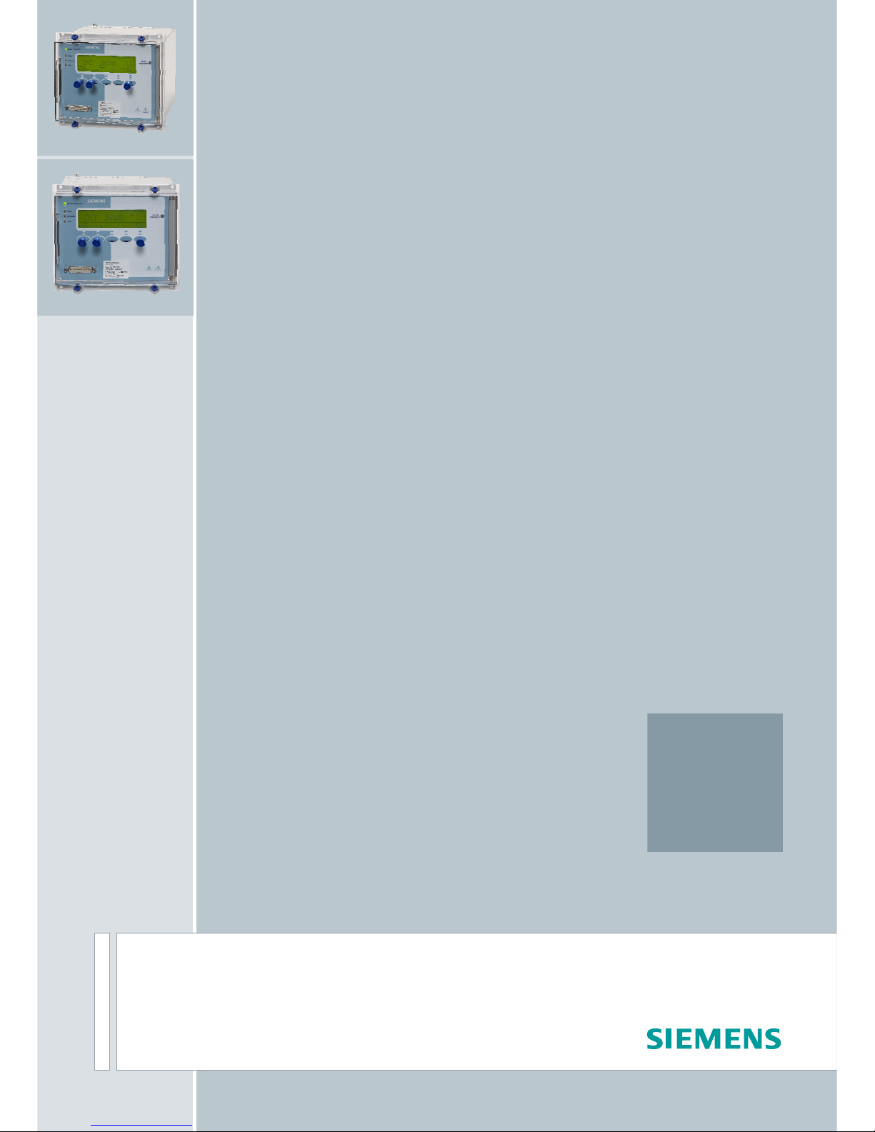
Operate
Time
Relay
Deadband
80% Volts
Initial
Delay
IDMTL
Initial
Delay
DTL
Initial
Delay
Figure 2
The MicroTAPP provides a system, at each point where voltage is regulated, that operates at all times with
minimal human intervention and is capable of optimal operation under various power network arrangements.
A diagram showing the general layout of the relay fascia is shown at the end of this section in appendix A.
When selected to ‘automatic’ mode, the voltage regulating relay controls the transformer tap changer. Voltages
which are outside set voltage limits (deadbands) automatically initiate the operation of the transformer tap
changer in order to restore the secondary voltage to normal.
When selected to ‘manual’ mode, the voltage can be regulated via the relay manual raise/lower control integral
switches. The application section of this document gives more information regarding other tap change controls
that may be incorporated into the voltage control scheme.
The operating characteristics of the voltage regulating relay are such that a raise or lower command will only be
issued after an initial time delay as set on the voltage regulating relay. A definite time characteristic or an
inversely related initial time characteristic is selectable for voltage in excess of the Relay Deadband . Figure 2
shows the characteristics for both types of time delay setting.
The MicroTAPP provides two initial time delays, a definite and an inverse characteristic. The inverse time delay is
dependant on the voltage deviation from the normal band and is defined by:-
Vtarget - Vmeasured
Vban
d
x tsetting
=t
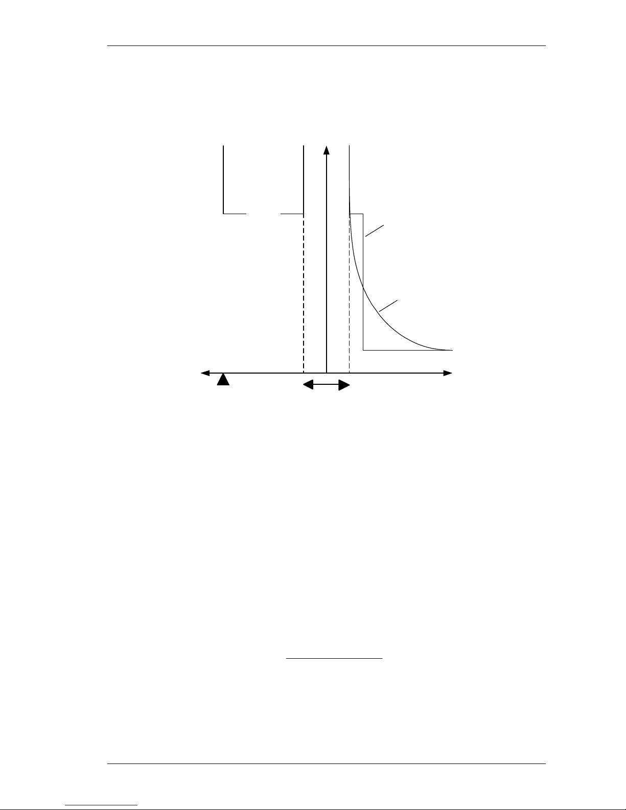
The initial/inter-tap delay timers are designed to operate for optimum response to the ongoing voltage variation.
Following a voltage deviation from the normal band the default display changes to indicate the timer status,
consider Figure 3.
7SG15 MicroTAPP Description of Operation
©2013 Siemens Protection Devices Limited Chapter 1 Page 7 of 38
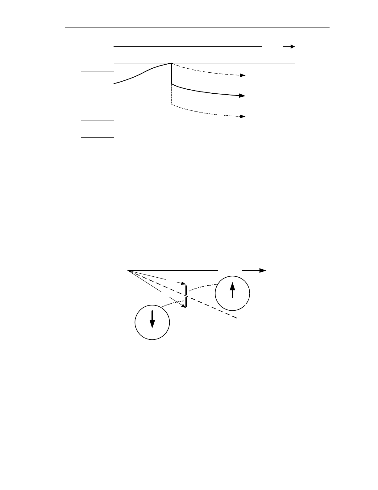
Figure 3
The initial delay timer increments (A) until the timer display is full, when a tap-change signal is issued (B). At this
time the display resets and the inter-tap delay timer increments, shown by C, while the initial timer is held at the
operative value. If the voltage is still abnormal after the first tap-change operation the inter-tap timer will continue
to increment and initiate a further corrective tap-change operation.
If after completion of the tap-change the voltage is normal the initial delay timer will ‘run back’ while the displayed
timer continues to increment (D). When the ‘hidden’ initial timer is equal to the displayed time the display will now
‘run back’ (E) to the reset position when the default display is restored.
Normally, voltage deviations take place slowly and are caused by changes in network loading. When a substantial
change in voltage is seen it is most likely the result of a network abnormality. As an abnormally high voltage can
cause damage to equipment if not corrected immediately the definite time delay of the MicroTAPP can be bypassed by a fast tapping feature in the event of substantial voltage excursions above the set band.
A fast tap occurs when the voltage rises to a level at least = Top of Dead Band + 2% of normal voltage for 2
seconds.
If the relay is allowed to make fast response to a substantial low voltage deviation, which is of a transient nature
(such as for an auto-reclose sequence) and the tap change is operated to correct the deviation, an unwanted
over-voltage will occur when the transient problem is corrected. For safety reasons, therefore, the IDMTL
characteristic and the fast tap response for the DTL are only enabled for voltages above the relay dead-band.
Following an initial tap change operation (IDMTL or DTL) any subsequent corrective signals for the same voltage
deviation will be delayed by a separate inter-tap time delay (definite time lag characteristic).
Monitoring of the voltage level is via separate connections and inputs to those used for voltage measurement.
Under and over-voltage blocking functions inhibit operation of the regulating relay when the supplied voltage falls
below, or rises above limits which are within the set alarm levels. Tap change operations that will correct the
abnormal voltage are allowed.
Where a 3 phase VT is used, each phase is monitored as a check against fuse failure.
Raise and Lower commands operate normally open relay contacts. Output contacts can be mapped to internally
generated alarms or lockout signals.

7SG15 MicroTAPP Description of Operation
©2013 Siemens Protection Devices Limited Chapter 1 Page 8 of 38
The following standard system conditions are catered for with minimal or no adjustment to the MicroTAPP: -
1 Where a transformer is in parallel with other transformers, either within a site or across a network, when set
to TAPP mode, the relay operates in order to: -
• maintain the system voltage at the correct level
• operate at a tap position where minimal reactive circulating current flows from or into any system
transformer which is a part of the network
2 In the event of a failure of communications either between grouped transformers or from a remote control
centre, the relay operates in a stand-alone mode until the fault is rectified
3 If a transformer in a group is switched IN, no significant change in voltage will occur
4 If a transformer in a group is switched OUT by use of the ‘prepare to switch out’ function, no significant
change in voltage will occur
5 The Load Drop Compensation (LDC) method maintains the voltage at the correct level regardless of the
number of transformers connected to a common busbar
6 Settings applicable to different network or busbar running arrangements can be applied to each relay and
implemented by a single instruction (either from a remote source or locally) or plant status change (operation
of a bus-section CB for instance)
7 Each relay independently protects against incorrect operation which would allow abnormal voltages to be
applied to the network
Up to 16 transformers operating in parallel can be controlled as a group.
4.2 Transformers in Parallel
With traditional schemes where 2 or more transformers are connected in parallel either within the same site or
across a network, a reactive circulating current will flow between them unless the following conditions are met: -
• The transformers are identical
• The transformers have the same number of taps and tapping interval
• The transformers are always on the same tap position
• The transformers have the same impedance
• The transformers are fed from the same primary source or, more correctly, have the same voltage applied to
the primary winding connections
These conditions put constraints on power system design, which are eliminated by the MicroTAPP voltage control
system that is designed to detect reactive current and bias the relay target voltage in such a way that the
circulating current is reduced to a minimum. Two methods of control are provided:
1 The TAPP system which uses an enhanced negative reactive circulating current principle.
2 Detection of circulating current between transformers connected to the same busbar but not through a
network.
For the purpose of explanation the circulating current method is described first, the most widely used and
preferred system, however, is the TAPP method which allows for transformers to be operated in parallel at any
point in a network, i.e. operate groups of transformers at different substations in parallel.
4.2.1 Circulating Current Control
As described previously the MicroTAPP uses a communication system for the transfer of load information to other
relays thus allowing each relay to determine the summed site load and power factor (I load) shown in Figure 4.
7SG15 MicroTAPP Description of Operation
©2013 Siemens Protection Devices Limited Chapter 1 Page 9 of 38
Voltage
IT1
IT1circ
IT2circ
IT2
I load
IT1load
IT2load
Figure 4
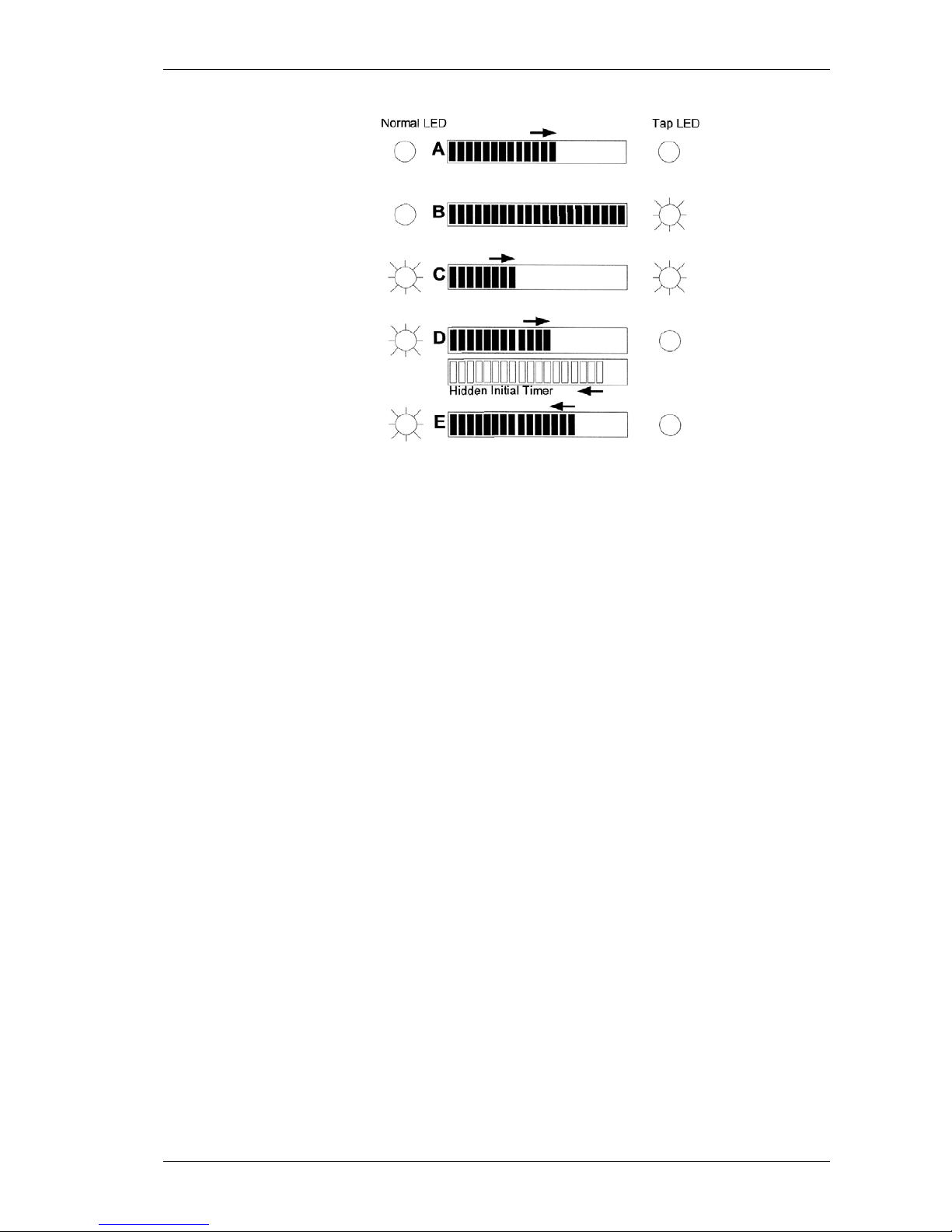
For explanation of the relay action consider a situation where 2 transformers are operating in parallel at a site.
Each MicroTAPP relay receives the same voltage by virtue of the common connection, represented in Figure 5 by
‘A’. Over time the busbar voltage changes, in this example it rises until the upper band limit is reached, point B.
As each relay is free to operate one will usually act first (T2 in this case) and initiate a tap change operation
before T1. When this occurs, the busbar voltage will be reduced by ½ of a tapping interval to point C. This
situation now results in a small circulating current which flows from T1 on the higher tap, IT1circ in Figure 3 and
into T2 on the lower tap, IT2circ.
The MicroTAPP control algorithm calculates the magnitude of the circulating current which is the vector difference
between load, IT1load, and the individual transformer current, IT1 in Figure 4 and determines the target voltage
bias value according to the following rules: -
• If reactive current flows OUT a bias equivalent to the change in voltage is added to the measured voltage
• If reactive current flows IN a bias equivalent to the change in voltage is deducted from the measured voltage
Referring again to Figure 5, for T2, the effective measured voltage is now reduced to D and for T1, which did not
operate, the measured voltage is returned to B.
The voltages measured by each relay are now different such that, if the voltage trend continues to rise T1 will tap
down, and the transformers will be on the same tap positions, or if the voltage trend is down, T2 will tap up and
the transformers will also be on the same tap positions.
Where the transformer are not identical, or the incoming voltage is different on each transformer, the MicroTAPP
relays will always operate according to the above rules and ensure that minimal circulating current flows between
transformers regardless of the actual tap positions.
This system of tap change control will operate at any system power factor but relies on the true measurement of
IT1load. MicroTAPP uses the MPPC system for the transfer of load information between relays allowing each to
determine the summed site load and power factor (I load) as shown in Figure 4. Unlike other relays that offer this
option, MicroTAPP does not require use of circuit breaker auxiliary switches.
7SG15 MicroTAPP Description of Operation
©2013 Siemens Protection Devices Limited Chapter 1 Page 10 of 38
Time
A
B
C
D
T1 measured voltage
T2 measured voltage
System voltage
Upper
Band
Lower
Band
Figure 5
It is not possible for this method of circulating current control to be used when networks are operated in parallel as
the summed load at that site can also contain reactive current flowing between remote transformers.
4.2.2 Negative Reactance circulating current control – TAPP
A modification of the circulating current principle is used to overcome the limitations of the circulating current
system described in the previous section and allow operation of transformers in any configuration, in parallel at a
site, or across a network.
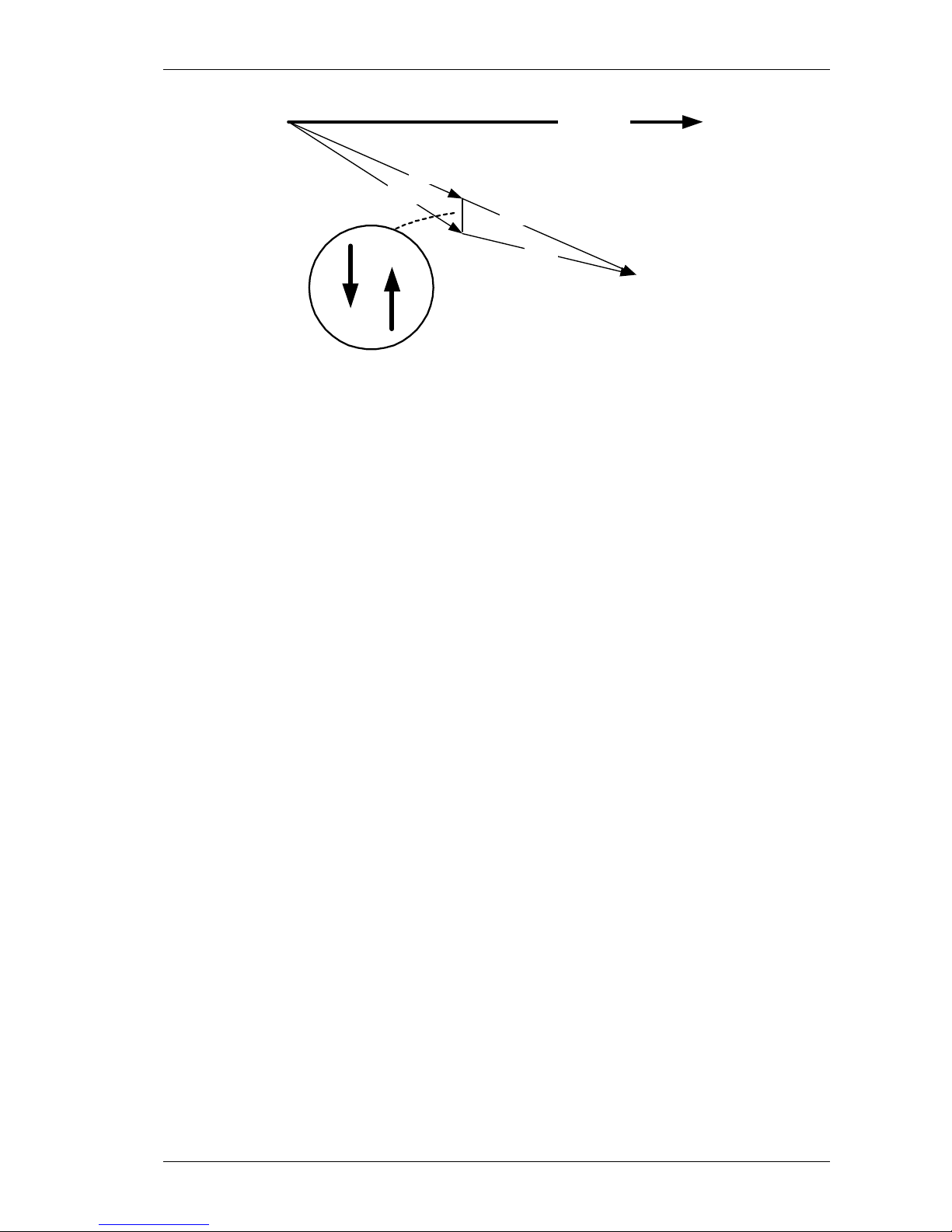
A network Power Factor setting is used to calculate the magnitude of circulating current as the vector difference
between IT1 (and IT2) and the transformer target load line at the target power factor. Figure 6 shows the situation
where T1 is exporting reactive current, either to an adjacent transformer or into the network. The relay will operate
to bring the voltage to the correct level (as described previously) in such a way as to reduce the magnitude of the
reactive current. If, as for the previous example, two transformers are in parallel at the same site the circulating
current will flow into T2 which will also act to correct the voltage while at the same time reduce the circulating
current to a minimum.
Load line at
Target PF
Voltage
IT1
IT1circ
IT2
IT2circ
Figure 6
Unlike the previously described circulating current method, the TAPP system does not require load information
from other transformers in order to minimise reactive current. As will be seen in the commissioning section of this
manual, the instrument display gives a reading of the network power factor which can be used to set the optimum
operating point of the relay.
Voltage control systems that use a conventional negative reactive circulating current method based on a 90°
VT/CT connection, are not accurate at typical system power factors. As the load on a transformer increases the
apparent measured voltage rises, causing the transformer to tap down, see Figure 7.

7SG15 MicroTAPP Description of Operation
©2013 Siemens Protection Devices Limited Chapter 1 Page 11 of 38
Voltage
IT1
-VXT1
Measurement
Error
Figure 7
When conventional negative reactance control is used the transformer current, IT1, is used to produce a voltage –
VXT1, which should have no effect on the relay for load current. When the load current power factor is less than
unity, as shown, an error voltage is introduced into the circuitry which causes the relay to measure an incorrect
higher voltage that results in a tendency to reduce the power system voltage below the required level.
MicroTAPP is set to operate at the true power factor. This gives reliable accuracy when set to the average system
power factor and overcome the problems associated with other schemes.
4.2.3 Master/Follower control
The MicroTAPP can be configured for use with a Master/Follower tap change control scheme; however this
arrangement is complex and imposes severe limitations on network operation. It is not recommended.
4.3 Load Drop Compensation
The MicroTAPP includes a ‘Load Drop Compensation’ facility which is be used to offset the effect of load related
voltage drops. Unlike normal controls that respond to transformer load only, the MicroTAPP uses a
communication system for the transfer of load information to other relays, thus allowing each relay to determine
the summed site load (I load) as shown in Figure 4. Regardless of the number of transformers in service at any
time the LDC effect will be accurate, unlike those systems where the transformer load and thus the LDC effect
changes as the number of transformers in a group changes.
A single control determines the LDC setting and is based on the load at the chosen power factor (a Z setting). It is
widely recognised that this arrangement gives the best overall predictable accuracy for load related voltage
boosting. Maximum LDC will be applied when the measured load is equal to the System Group Capacity setting.
4.4 MT102 Advanced Features
4.4.1 Description of Operation
MicroTAPP voltage control relay (VCR) can be provided with functionality that will allow effective control to be
exercised on either side of the transformer using a single fixed voltage transformer and includes load related
voltage regulation.
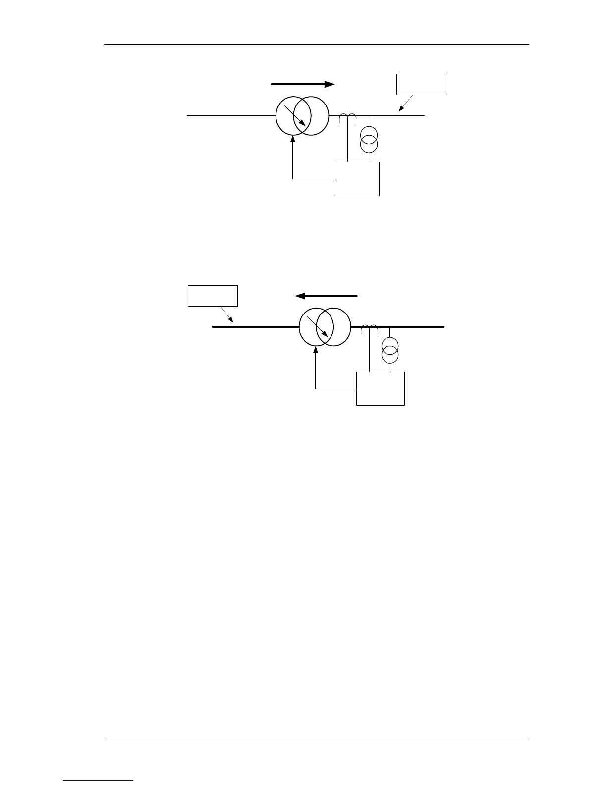
Figure 8 shows a normal arrangement for a voltage regulation system that employs a MicroTAPP relay taking a
voltage and current measurement input from the network side of the power transformer. Any adjustments to the
target voltage level are initiated by the VCR to drive a tap-changing mechanism that may be connected to either
the ‘primary’ or ‘secondary’ windings of the power transformer.
7SG15 MicroTAPP Description of Operation
©2013 Siemens Protection Devices Limited Chapter 1 Page 12 of 38
VT
CT
MicroTAPP
Power Flow
Controlled
Network
Figure 8
If a network configuration makes it necessary to change the controlled voltage point, a voltage and current
transformer would be required on the other side of the power transformer together with a complex switching
arrangement for the tap-changer control system. If the network running arrangement is such that the use of
generation make it desirable for the controlled network to be changed from one side to the other, automatic
voltage control may not be possible as shown by Figure 9.
VT
CT
MicroTAPP
Power Flow
Controlled
Network
Figure 9
The advanced functionality of the MicroTAPP uses algorithms that enable the terminal voltage of the nonmeasured side of the power transformer to be calculated and effective control to be carried out without a
requirement for any additional inputs. Information relating to the transformer is required as can be seen by
reference to the relay setting section of this document and covers the following situations: -
4.4.2 Location of tap-changer, HV or LV side
Normally the controlled voltage winding is the un-tapped winding and the tapping interval is an equal percentage
change for each tap position, based on a constant nominal output voltage on the fixed winding. If the controlled
voltage point is on the tap-change side the effective voltage change for each tap position will not be constant
across the tapping range.
The MicroTAPP relay uses the location of the tap-changer, with other information, to correctly determine the step
by step voltage level.
4.4.3 Change in voltage per tap
The change in voltage per tap is required and as described above the actual effect is dependent on the location of
the tap-changing mechanism. The value of tapping interval that is input into the relay is a single calculation as
follows: -

7SG15 MicroTAPP Description of Operation
©2013 Siemens Protection Devices Limited Chapter 1 Page 13 of 38
The tap spacing is calculated regardless of the tap-changer location: -
Vhi* = Highest voltage of the variable voltage winding (voltage as nameplate)
Vlo* = Lowest voltage of the variable voltage winding (voltage as nameplate)
Vnom* = Nominal voltage of the variable voltage winding (voltage as nameplate)
Tap = Number of taps (not tap intervals)
* Irrespective of the actual tap changer location
Tap spacing % = (Vhi - Vlo) x 100
Vnom x (Tap-1)
4.4.4 Single phase or 3 phase units
This setting determines load current for the transformer full load rating.
4.4.5 Direction of tap-changer for voltage increase
Some tap-change mechanisms operate to increase voltage by reducing the tap position. This setting allows for
this situation.
4.4.6 Transformer impedance
Transformer impedance is used by all MicroTAPP relays for control of circulating current and, in this application,
for the calculation of winding voltage drop.
4.4.7 Nominal voltage or winding load drop compensated target settings
In some applications where large transient loads are supplied it may be desirable to ignore the transformer
voltage drop and control the voltage at an effective nominal level. This setting allows for this requirement.
4.4.8 Dead-Reckoning Block
Since the MT102 may be controlling the voltage on the opposite side of the Power Transformer from its
measuring point, it is important that the Tap Position reported to the Relay by the TPI is correct. The Relay will
therefore compare the Tap Position received from the TPI with its own "Dead-Reckoned" Tap Position. If a
discrepancy is found the Relay will Alarm "Dead Reckoning Block" and block subsequent tap changes. This will
only be reset once a correct Manual Raise/Lower operation has been carried out.
4.4 MicroTAPP–MicroTAPP communications
At a site each MicroTAPP can connect to other MicroTAPP relays through a screened twisted pair cable. The
MicroTAPP Peer to Peer Communication system (MPPC) is used to transfer data between the relays relating to
the overall operation of the MicroTAPP group at a site. If a MicroTAPP relay is de-energised, communications
between other relays connected to the twisted pair cable is not affected.
4.5 Low Frequency Voltage Reduction
Where voltage reduction is used for load reduction purposes, usually to offset a shortfall in available generation,
the relay can be configured to automatically initiate tap change operations. The power system frequency is
continually monitored, if the frequency falls below a set level the target voltage setting is dropped by 5% to effect
an immediate voltage reduction.
4.6 Transformer Switch out
When one transformer of a group is switched out of service a voltage drop will occur as additional load is ‘picked
up’ by the remaining transformers, particularly if the transformers are heavily loaded and have a high impedance.
The effect can be eliminated if the individual transformer tap changers are operated to offset the voltage drop
prior to switch-out, e.g. raising the tap position of the transformer that will remain in and lowering the tap position
of the transformer that is to be switched out.
On receipt of a signal (switch out command), MicroTAPP relays (allocated to a group) can be configured to
communicate and operate each tap changer in such a way that minimal change in voltage will occur when the
transformer is switched out. When the optimum tap positions are achieved a completion signal is returned.

7SG15 MicroTAPP Description of Operation
©2013 Siemens Protection Devices Limited Chapter 1 Page 14 of 38
When the load current is removed from the transformer to be switched out, the remaining relays return to normal
tap change control. If the load current is not removed, after a period of time the relays reset to normal operation.
The switch-out command can be initiated either by a SCADA signal, from a PC via a communications network or
from a hard wired local control switch.
4.7 Transformer Switch in
Normally when a second transformer of a pair is switched into service the busbar voltage will increase. If the
transformers have a high impedance and the load is high, the voltage increase can be significant. The MicroTAPP
relay can avoid this increase by tapping the unloaded transformer prior to it being loaded.
The transformer should be energised by closing the HV CB and waiting for the unloaded transformer to complete
any tap changes. The MicroTAPP relay will immediately operate the tap changer of the unloaded transformer to a
position whereby the open circuit terminal voltage is equal to the busbar voltage. Once the NORMAL LED is
illuminated the transformer can be energised by closing the LV CB.
The MicroTAPP controlling the loaded transformer sends load data to the unloaded transformer via the MPPC.
This allows the unloaded transformer to be tapped to the desired voltage target prior to the LV CB closing. It also
allows any LDC compensation to be included into the tap change control.
When the circuit breaker is closed, there will be no significant change in busbar voltage and the relays will then
tap to minimise circulating current in the normal way. The advantage of this control switching sequence is the
customer does not experience a large voltage fluctuation whilst switching transformers in and out of service.
4.8 Relay Settings
Settings applicable to a particular site can be applied to the relay either locally from the relay display, a PC via the
relay fascia serial port, or remotely over a communications link via the rear mounted fibre optic connections.
8 groups of settings can be stored by the relay, at any time only one group is used by the relay for control. When
the relay is energised, it will operate with the settings group that was last applied.
The MicroTAPP is designed to function as an integral control device within the Transformer/Site configuration, in
this respect information relating to the installation is used by the relay as follows: -
Site data - number of transformers forming a group etc.
Transformer Data - rating, impedance, VT and CT details etc.
Tap change - number of steps, type etc.
Network data - Power Factor, system voltage, group capacity etc.
Voltage control - Basic, band, LDC etc.
4.8.1 Basic Set-point
The basic setting determines the operational target voltage for the relay with the transformer at no load. If LDC is
not used the target voltage will be the basic setting.
4.8.2 Normal voltage deadband
A deadband setting with a range that will enable the voltage to be controlled within satisfactory limits for a
practical number of tap changing operations is provided.
If the voltage fluctuates about the deadband, a corrective tap change operation will take place if the average
voltage level deviates from the relay setting.
4.8.3 Load Drop Compensation (LDC)
The relay LDC corrective effect is based on system group capacity at the system power factor. Use of the LDC
setting is discussed in the applications section of this manual.

7SG15 MicroTAPP Description of Operation
©2013 Siemens Protection Devices Limited Chapter 1 Page 15 of 38
4.8.4 Circulating Current Compensation
The relay will control group transformers in parallel without recourse to a complex Master/Follower scheme. Two
methods can be used: -
1 Reactive current minimisation, an enhanced version of the TAPP patented system as used with the
SuperTAPP range of Siemens Protection Devices Ltd equipment. Using this system, widely recognised for its
operational advantages, transformers can operate in parallel either at a site or across a network thus giving
greater network flexibility.
2 Circulating current control, this method enables transformers to operate in parallel when connected to a
common busbar at a site at any power factor, but NOT across a network or between groups of busbars.
The relay response for each method, when selected, is determined by the transformer characteristics entered into
the set-up menu.
4.8.5 Tap Stagger
The MicroTAPP can still be utilised for the export or import of reactive current (tap stagger). The voltage control
menu is used to set the magnitude of the reactive current and a status input can be set to initiate the tap stagger
process. The value of reactive current is set as a percentage of the transformer group full road rating, i.e. for a
9MVA group a setting of +10% would result in an exported reactive current of 0.9MVAr and a -10% setting would
result in an import of 0.9MVAr.
4.8.6 Time Delays for Operation
When a busbar group voltage is outside upper or lower deadband, the initial corrective tap control output is
delayed by a pre-set time. This time delay is the ‘initial tap time delay’ as described previously and shown in
Figure 2.
Where the voltage is drifting in and out of the deadband, the initial delay time-out is determined by the difference
between the accumulated times that the voltage is outside and inside the deadband. The relay counts up to the
initial tap delay time for the period that the voltage is outside the deadband. If before the initial tap delay time is
reached the voltage returns within the deadband, then the equipment will count down for the period that the
voltage is within the deadband.
In the event of a voltage ‘swing through’ the relay accumulates voltage excursion times from both the lower and
upper deadbands as described above. The first time delay to expire will initiate the appropriate corrective tap
change operation.
If more than one tap change operation is required for correction of a voltage deviation, subsequent tap change
operations are determined by an ‘inter-tap delay’ setting which has a definite time characteristic. The time is
settable from the menu and should normally be slightly longer than the tap changer operating time.
5 Control
The relay provides for both Manual and Automatic control of the tap changing system.
The relay is configurable for either Local control, or Remote control through a communication system from a
control centre. The communication medium may be serial communications or from hard wired contacts.
If manual control is exercised from a point where an indication of the power system voltage is not available the
relay can be arranged to inhibit tap change operations that would drive the system voltage to an abnormal level,
e.g. control at the tap changer mechanism.
5.1 Control Points
Electrical control of a tap change mechanism is normally exercised from three points: -
5.1.1 At the tap change mechanism
A Local/Remote selector switch at the Tap Changer is connected to the MicroTAPP enable input. When set to
Local, this disables tap change operation from all other control points. When set to Remote, control is enabled
from the MicroTAPP relay.

7SG15 MicroTAPP Description of Operation
©2013 Siemens Protection Devices Limited Chapter 1 Page 16 of 38
5.1.2 At the voltage control relay panel
A Local/Remote selector switch on the MicroTAPP, when set to Local, disables control from a remote control
centre. If the tap change is set to Local at the tap change mechanism, Auto/Manual selection can still be altered
and will take effect when the MicroTAPP is enabled.
5.1.3 At a remote site
When the MicroTAPP is set to Remote, controls can be selected and operated from a remote control centre
providing the selector switch at the tap change mechanism is also set to Remote. If not, Auto/Manual selection
can still be altered and will take effect when the MicroTAPP is enabled.
5.2 Control Switches
The MicroTAPP has integral control switches that can also be operated from a remote control centre, with the
following functions: -
Remote / Local
Auto / Manual
Auto / Manual
Auto Control of
Tap Changer
Manual Raise/Lower from
Comms and/or Status
Inputs
Auto Control of
Tap Changer
Manual Raise/Lower at
Relay fascia
Figure 10
5.2.1 Local/Remote
A switch is provided to allow for the selection of control to be at the relay or from a remote location, normally a
control centre. Remote control is via the communications or status inputs.
5.2.2 Auto/Manual
This switch sets the relay to Automatic or Manual voltage control.
When the MicroTAPP is set to ‘Manual’, the relay will not attempt to correct the voltage automatically. To aid
Manual control, the relay status LEDs show the voltage level in respect of the relay deadband. A digital reading of
the actual voltage level and the tap position is also given.
5.2.3 Raise/Lower
When the Auto/Manual switch is set to Manual this switch allows the tap changer to be operated either to increase
the tap position or reduce the tap position.
The control is operative with the transformer energised or de-energised.

7SG15 MicroTAPP Description of Operation
©2013 Siemens Protection Devices Limited Chapter 1 Page 17 of 38
6 Protection
A comprehensive monitoring of the voltage control system is incorporated that will detect and prevent abnormal
power system voltages either from incorrect operation of a tap changing mechanism or from incorrect control
signals.
6.1 Voltage and Current
6.1.1 Measured voltage outside normal range
The voltage monitor is connected to separate inputs on the relay and not those used for voltage measurement,
i.e. where a 3 phase VT is used A-B phase may be for measurement and B-C phase for measurement monitoring,
see Figure 11.
If the measured system voltage is less than a pre-set under-voltage limit or greater than a pre-set over-voltage
limit, the relay inhibits the appropriate tap control outputs to the relevant transformer but allows tap change
operations that will correct the abnormal voltage. An under or over-voltage alarm is generated if the abnormal
voltage reaches excessive levels for a time equal to the Alarm Time setting. The under-voltage and over-voltage
alarm level is settable to accommodate the range of voltage allowable by the voltage control settings.
Voltage Measure
Voltage Monitor
C25
C26
C27
C28
VT phase A
VT phase B
VT phase C
Figure 11
As a guideline, the maximum voltage that should normally be seen is = Target Level + Band + LDC. Note that the
Target Level might be the "Target Voltage" setting or any relevant "Auxiliary Target" setting. So, for example, if
the Target Voltage is 98%, the Band is +/- 1.5% and the LDC is 5%, the upper alarm setting should be at least
98% + 1.5% + 5% = 104.5%. In practice a further 1% should be added for tolerance. The actual Over-voltage
Alarm level would therefore be 105.5%.
The minimum voltage that should normally be seen is = Target Level - Band. Note that the Target Level might be
the "Target Voltage" setting or any relevant "Auxiliary Target" setting. So, for example, if the Target Voltage is
98%, the Band is +/- 1.5% and the minimum Auxiliary Target is 97%, the lower alarm setting should be no more
than 97% - 1.5% = 95.5%. In practice a further 1% should be deducted for tolerance. The actual Under-voltage
Alarm level would therefore be 94.5%.
The voltage monitor automatically blocks control signals that would drive the system voltage in the wrong
direction. The overall action of the monitor is shown in Figure 12.

7SG15 MicroTAPP Description of Operation
©2013 Siemens Protection Devices Limited Chapter 1 Page 18 of 38
Figure 12
Assume that the voltage is approaching the high voltage setting level. If a tap change is issued it will be an
instruction to lower the voltage, therefore for safety, the raise output logic can be blocked. The same argument
can be applied to the low voltage setting level.
The voltage blocks will take effect at (upper voltage level - total dead-band) and (lower voltage level + total deadband). Using typical settings as an example, if the monitor ‘high' alarm setting is 105% and the ‘low’ alarm setting
94% and the relay band setting is ±1.5%, the ‘raise’ output will be blocked at 102% and the ‘lower’ output at 97%.
When the tap changer is operated manually from the tap change controls at the tap changer, the MicroTAPP can
still be used to prevent incorrect control signals by routing the tap changer raise and lower signals through the
MicroTAPP Block Raise and Block Lower output contacts respectively.
When the tap changer is operated manually from the relay, or from a remote control centre, all manual control
signals will be allowed. Such operations should therefore only be carried out if there is an indication of the voltage
level available at the point of control.
6.1.2 Voltage transformer faulty
Where a 3 phase VT is used the relay monitors all voltages in order to ensure the integrity of the VT secondary
output. Any abnormalities detected (HV fuse blown for instance) will inhibit the voltage raise outputs from the relay
and initiate an alarm. A VT failure is assumed when:-
5V Vpps when 10% 100% x
Vpps
Vnps
≥≥
A VT / VT fuse failure will result in misleading phase information being placed on the MPPC by the MicroTAPP
which has detected the failure. This will compromise the operation of all the MicroTAPP’s sharing load information
over the MPPC when they are set to operate in Circ. Current mode of control. For this reason, failure of a VT / VT
Fuse will result in all the MicroTAPP’s sharing the MPPC switching from Circ. Current to TAPP mode of control for
the duration of the failure. Care should be taken, therefore, to set a valid System Power Factor setting even when
using Circ. Current mode of control.
Note that this feature will only be available when the ‘MPPC Failure Detection’ is Enabled.

7SG15 MicroTAPP Description of Operation
©2013 Siemens Protection Devices Limited Chapter 1 Page 19 of 38
6.1.3 Load Current
If the true load current is greater than a pre-set limit, the relay system will inhibit tap control outputs to the and
generate an over-current alarm, unless the situation is caused by circulating current flowing between
transformers, in which case tap changing will be enabled that will reduce the circulating current, see Figure 12.
6.2 Tap Changer
The tap changer operation is monitored for a mechanism, wiring or relay fault. The following is provided: -
6.2.1 Tap Change Runaway
Following a tap change instruction the first incorrect tap change operation is detected immediately by the
MicroTAPP and further operations are inhibited. An incorrect tap change operation is defined as ‘a tap change
operation that is not initiated by a true control signal’. As an example, a slow to clear ‘raise’ contactor may allow a
motor drive to continue driving the mechanism at the end of a tap change cycle such that the tap change
maintaining switch recloses thus allowing the tap change to ‘run away’.
The MicroTAPP intelligently monitors the relationship between the initiating control signals, the tap change ‘in
progress’ inputs and the tap position.
For a tap change to be correct, the following sequence must take place:-
1 A control signal must be issued to initiate the process
2 The tap position must change to a new position
3 The tap change mechanism must stop completely
A ‘Tap In Progress’ (TIP) auxiliary switch is closed while the tap is not at the rest position and used to indicate and
monitor the operation of the mechanism. Figure 13 shows the MicroTAPP input status signals during a normal tap
change operation.
Lock Out
IP Indication
Operation
Reclaim
Time
Raise/Lower
In Progress
TPI
Time
Normal Operation
Figure 13
To confirm correct operation a definite break between successive tap change operations must be detected.
On detection of the completion of each signal the MicroTAPP checks that the mechanism has stopped by
monitoring for no further signals, shown in the Figure as the ‘reclaim time’, set at 2 seconds for the MicroTAPP. If
a further operation is detected in the reclaim time, a runaway condition is assumed and the relay will lockout
The TIP LED is maintained until all signals are removed, the tap position has changed and the reclaim time has
expired.

7SG15 MicroTAPP Description of Operation
©2013 Siemens Protection Devices Limited Chapter 1 Page 20 of 38
For an incorrect tap change, Figure 14, where the mechanism over-runs, or continues to operate, a new control
signal AND/OR ‘in progress’ is detected before the internally generated reclaim time has expired. The tap change
has not satisfied rule 3 above, and a further tap position change will result in a lockout signal and the TIP LED will
flash.
Raise/Lower
TPI
Lock Out
Time
In Progress
Runaway Condition
Next cycle starts before
Reclaim time end
IP Indication
Figure 14
The runaway prevention unit also protects against a runaway situation during push button operation. Unwanted
lockouts in manual control are prevented by avoiding further operations until the "In Progress" LED is
extinguished.
If a lockout is required the relay can be configured to operate contacts both for lockout and alarms. Output
contacts can be used for the tripping of a mechanically latched contactor or the permissive operation normally
open contactor.
6.2.2 Tap Change Incomplete
If a ‘raise’ or ‘lower’ signal is sent to initiate a tap change operation and the operation is not completed, then the
relay can be configured to issue an alarm and lockout the tap-change motor power supply. For a tap change
operation to complete, a pulse must be seen at the ‘In Progress’ Status Input and the indicated tap position must
change.
6.2.3 Limit of Tap Change Range
If the tap changer is on either the top or bottom tap position, an "End of Tap Range" alarm is issued. Further tap
changes will be inhibited if they attempt to drive the tap changer beyond its extreme positions.
6.2.4 Tap Not Achievable
If the tap changer is on either the top or bottom tap position and the voltage goes out of the Dead-band in such a
direction that a corrective tap change would be required beyond the tap changer extreme positions, a "Tap not
achievable" alarm will be issued.

7SG15 MicroTAPP Description of Operation
©2013 Siemens Protection Devices Limited Chapter 1 Page 21 of 38
7 Other Features
7.1 Instrumentation and Metering
The MicroTAPP gives indications, shown by reference to the general layout in appendix A as follows: -
7.1.1 System ID
The relay has provision for input of a control system ID, e.g. "Transformer 1".
7.1.2 Control Switches
The relay status is indicated on the LCD display. The controls are integral within the voltage control relay, the
display shows the control switch selection, see Figure 16.
7.1.3 Relay Healthy
An LED shows that the relay is operating correctly or has malfunctioned.
7.1.4 Voltmeter
Digital presentation of the power system voltage is shown on the LCD.
7.1.5 Voltage Trace
A voltage level trace is shown on the LCD.
This can be configured for a window of 15 minutes or 1 hour.
7.1.6 Tap Position Indicator (TPI)
Digital presentation of tap position is shown on the LCD.
Some tap changers have special positions which operate to re-arrange the winding configuration but do not alter
the voltage. When at these positions a single tap change control will result in more than one tap change
operation. The positions may also be indicated as the same position and labelled with suffix letters, i.e. 8A, 8B,
8C.
A system that allows for presentation of the tap position as indicated on the tap change mechanism is integrated
into the TPI set-up menu, accessed by use of a ‘tap customisation sub-menu'. If a tap position is maintained as
the same position through the ‘transfer’ cycle, the positions can be re-numbered as the same position, for
example 7, 8, 8, 8, 9. To indicate that these tap positions are special, they should also be marked as ‘T’ to
indicate a 'Transfer' position, i.e. 7, 8T, 8, 8T, 9. This prevents a Runaway condition being detected.
The use of the sub-menu is best understood from the following examples.
A tap changer with top tap of 15 but with tap through positions labelled 8A, 8B and 8C.
1 2 3 4 5 6 7 8A 8B 8C 9 10 11 12 13 14 15
The total number of positions are 17 and entered in the in the settings/tap change/ no. of taps as 17. The tap
customisation sub-menu is used to change the tap positions as follows:-
1 2 3 4 5 6 7 8T 8 8T 9 10 11 12 13 14 15
A tap changer with a tapping range from -5 through 0 to +11 the total number of positions is 17 and entered in the
settings/tap change/no. of taps as 17.

7SG15 MicroTAPP Description of Operation
©2013 Siemens Protection Devices Limited Chapter 1 Page 22 of 38
The tap customisation sub-menu is used to change the tap positions as follows:-
-5 -4 -3 -2 -1 0 1 2 3 4 5 6 7 8 9 10 11
7.1.7 Instruments
Extensive instrumentation is available from the LCD display or a remotely connected PC. Figure 15 shows the
general format of the instrument display, the complete range of instrumentation is listed in section 9, Settings and
Displays.
SYSTEM VALUES
EXIT
NEXT
CANCEL
20/09/1999 16:08:40
11.3kV 18.0MVA 0.97PF
Figure 15
7.2 Data Storage with Date and Time
Data records are available in three forms, namely fault records, graphical records and event records.
7.2.1 Fault Records
This screen enables the 10 most recent tap-changer faults to be viewed. For each, the date and time of the fault
and a short description of the events leading to the fault are provided.
Following maintenance all fault and any maintenance alarms can be cleared using the button labelled ‘Reset’
whereupon normal operation of the MicroTAPP will resume.
The reset button is available in place of the TEST LED function on the screen shown by Figure 16.
TRANSFORMER 1
10.9
07
kV
-1h
LOCAL AUTO
TAP
CONTROL
MENU TEST LEDS
TAP
Figure 16
7.2.2 Graphical Records

7SG15 MicroTAPP Description of Operation
©2013 Siemens Protection Devices Limited Chapter 1 Page 23 of 38
Recordings of all operational data, voltage level, transformer load, summed load etc. are available for up to 24
hours from the relay.
7.2.3 Event Records
The event recorder feature of the relay allows the time tagging of any change of state of the relay. Each event is
logged with the full date and time and actual event condition every 50ms. The following events are logged:-
• Change of setting (though not the actual setting changes). Also indication of which group of settings is active.
• Change of state of Output Relays
• Change of state of Status Inputs
• Operation of controls (Auto/Manual etc.)
• Issue of tap change operations
• Relay Reset
The event storage buffer holds 200 records. When the event buffer is full, then any new record over-writes the
oldest.
Event records are stored in RAM with a capacitor providing back-up during breaks in auxiliary supply.
7.3 Communications
Two fibre optic communication ports are provided. Communication is compatible with the IEC60870-5-x FT 1.2
transmission and application standards.
A user friendly software package available on the Siemens Protection Devices Ltd website, Reydisp Evolution, is
freely available to allow transfer of the following:
• Relay settings
• Graphical records
• Event records
• Instruments and meters
• Control Functions
Communications operation is described in detail in the Siemens Protection Devices Ltd technical report
"Communications Interface Manual".
7.4 Self Monitoring
The MicroTAPP incorporates a number of self-monitoring features that initiate a reset sequence which can be
used to generate an alarm output. In addition, the Relay Healthy LED gives visual indication.
A watchdog feature monitors the microprocessor. The relay program memory is continuously checked for data
corruption. The power supply is continuously supervised. Any failure is detected with sufficient time warning so
that the microprocessor can be shut down in a safe and controlled manner.
7.5 Password Feature
The programmable password feature enables the user to enter a 4 character alpha-numeric code. As soon as the
user attempts to change a setting the password is requested before any setting alterations are allowed. Once the
password has been validated, the user is said to be "logged on" and any further changes can be made without reentering the password. If no more changes are made within 1 hour then the user will automatically be "logged
out", re-enabling the password feature.

7SG15 MicroTAPP Description of Operation
©2013 Siemens Protection Devices Limited Chapter 1 Page 24 of 38
Note that the password validation screen also displays a numerical code. If the password is lost or forgotten, this
code can be communicated to Siemens Protection Devices Ltd by authorised personnel, and the password can
be retrieved.
The relay is supplied with the password set to "NONE" which means the feature is de-activated.
8 User Interface
The user interface either via the LCD or a PC is designed to provide a user-friendly method of entering settings
and retrieving data from the relay.
8.1 General Arrangement
The MicroTAPP relay fascia includes a 40 character by 8 line, back-lit, liquid crystal display, 5 light emitting
diodes and 5 push buttons. Appendix A shows the layout for the E8 case size.
Detailed drawings for both the E8 and E12 wiring connector blocks are available from the Siemens Protection
Devices Ltd website.
8.1.1 Liquid Crystal Display
The liquid crystal display is used to present settings, instruments and fault data in a textual format.
The display contrast is factory set. It can be adjusted if required as follows:-
1. Press and hold the right most button.
2. Press either the left most or second left buttons to increase or decrease the contrast.
8.1.2 LED Indications
8.1.2.1 MicroTAPP Healthy
A green LED labelled ‘Relay Healthy’ is provided.
When the relay is powered up and running normally the LED will be on permanently. If a permanent fault is
detected by the internal self-monitoring algorithms and watchdog the LED will flash continuously.
8.1.2.2 Voltage Normal
A green LED indicates that the measured voltage is normal.
8.1.2.3 Voltage High
A red LED indicates that the measured voltage is above the relay deadband setting. If the over-voltage monitor
has detected a failure the LED will flash.
8.1.2.4 Voltage Low
A red LED indicates that the measured voltage is below the relay deadband setting. If the under-voltage monitor
has detected a failure the LED will flash.
8.1.2.5 Tap in progress
An amber LED indicates that the tap change mechanism is in the operating state. If the tap change monitor has
detected a failure the LED will flash.
8.2 Keypad and Display
Five push buttons are used to control and set-up all aspects of the voltage control system. The use of each button
is indicated by a label above the button in the lower portion of the LCD.
When the voltage is ‘normal’ a graphical display showing the previous 15 minutes or one hour of voltage level is
displayed together with the measured system voltage and the tap position.

7SG15 MicroTAPP Description of Operation
©2013 Siemens Protection Devices Limited Chapter 1 Page 25 of 38
Note that applying Auxiliary Target Voltages, Circulating Current compensation or Frequency compensation will
not adjust the graphical display target voltage. In some cases, therefore, the voltage trace will be outside the band
without Raise or Lower operations being initiated.
When the measured voltage makes an excursion from normal, the central area of the LCD changes to indicate
the progress of the time-out period, see Figure 17. Two indications are given one for ‘high’ and one for ‘low’,
normally only one bar is visible.
TRANSFORMER 1
10.9
07
kV
LOCAL AUTO
TAP
CONTROL
MENU TEST LEDS
TAP
'High' time delay
'Low' time delay
Figure 17
If the voltage level is such that it returns within the deadband before completion of the timeout period the timer will
‘run back’, for a DTL setting the runback rate is equal to the ‘run up’ rate.
Each out of band timer is independent, if a voltage ‘swing through’ occurs the display will show both time-outs,
one increasing and one decreasing. The first timer that times-out will initiate a tap change in the appropriate
direction.
When the buttons are operated the labels will change to indicate other functions. If a fault has occurred the ‘TEST
LEDS’ button is automatically changed to ‘RESET’ and allows the fault to be cleared.
Operation of the ‘Tap Control’ button changes the LCD display to that shown in Figure 18 and gives a graphic
display that allows selection of the tap change control to be changed by the ‘move’ button as required by site
operating conditions, the Figure shows the auto/manual switch selected for operation. The function of the push
buttons is also changed to enable the control switches to be operated.
Only three push buttons can be used when the relay cover is on, the two left most and the right hand button.
These allow selection and operation of the tap change but give read only access to relay setting menus and
stored fault data.
LOWER RAISE LOCAL REMOTE
EXIT
AUTO/
MANUAL
MOVE ->
MANUAL/AUTO
TAP 7
11.2kV
Figure 18
In addition, the following warnings can be displayed;

7SG15 MicroTAPP Description of Operation
©2013 Siemens Protection Devices Limited Chapter 1 Page 26 of 38
Locked Out The Relay has Locked Out.
V out of band The voltage is outside the Dead Band but the Relay is under Manual control
and so cannot correct it automatically.
V very low The voltage is below 80% of the nominal Primary Voltage.
No voltage The voltage is below 20% of the nominal Primary Voltage. This will reset only
once the voltage has returned to 70% of its nominal level.
TPI fault Dead-reckoning Error detected or Tap Position is 0. [MicroTAPP 102 only]
Remote VT fuse blown VT / VT Fuse failure reported over the MPPC
Switched to TAPP mode Control mode switched from Circ. Current to TAPP due to MPPC or remote
VT / VT Fuse failure
The complete range of controls and menu functions are detailed in the SETTINGS AND DISPLAY section of this
document.
8.3 Serial communications port
A 25-pin isolated RS-232 is provided for access to the relay’s stored data and settings. The PC or laptop
computer used should be capable of driving the port with at least 7mA at 7V.

7SG15 MicroTAPP Description of Operation
©2013 Siemens Protection Devices Limited Chapter 1 Page 27 of 38
9 Settings and Displays
The basic settings/displays flow diagram is shown in Figure 19. This diagram shows the main modes of display,
the Settings Mode, Instrument Display Mode and the Fault Data Display Mode. Intuitive operation of the push
buttons allows each mode to be entered where further menu options enable settings to be entered. At each level
a push button can be used to return to a higher menu level.
Figure 19
9.1 Settings Mode
For correct operation the MicroTAPP relay requires information regarding the network to which it is connected.
Information relating to the transformer characteristics, the tap changer, other transformers operating in parallel,
network parameters and voltage levels are entered as shown in Figure 20.
Figure 20
MENU
SETTINGS MODE
INSTRUMENTS
FAULT DATA

7SG15 MicroTAPP Description of Operation
©2013 Siemens Protection Devices Limited Chapter 1 Page 28 of 38
NOTE: [101] MicroTAPP 101 only
[102] MicroTAPP 102 only
System Configuration
Active Group
8 Settings Groups are provided.
Selects the Group in use.
View/Edit Group The Settings Group displayed on the LCD.
Status Select Group Mode
Configures the "Select Group" status inputs as either Level or Edge
Triggered. If Level Triggered, MicroTAPP will change its active settings
group when one of the "Select Group" inputs becomes active, and that
change will remain in effect until the input has become inactive. If other
"Select Group" inputs become active during this time they will be ignored. If
Edge Triggered, MicroTAPP will change its active settings groups for every
inactive-active transition at the appropriate "Select Group" input.
Relay Identifier Characters and numbers can be used to identify the Relay. The identifier
appears in the top left hand side of the display.
Set Date Relay date.
Set Time Relay Time.
Voltage display time Length of the historical voltage trace.
MPPC Failure Detection Enables inter-relay Communication Failure Detection. If enabled, the “MPPC
Failure” output relay can be allocated to send an alarm.
Change Password 4 character code. Allows password protection of the Relay settings.
By default this is set to NONE - no password.
Local / Remote Control Defines method of Local / Remote control - at the Relay Keypad or through
a Status Input.
Transformer
Transformer Number Where the Relay is configured to communicate with other units using the
MPPC it is important that each MicroTAPP is given a unique identifying
number. For example, if two transformers, T1 and T2, are installed, it would
be logical to use “1” as the identifier for the T1 Relay and “2” as the identifier
for the T2 Relay.
Transformer Capacity The Transformer Full Load continuous rating.
Transformer Impedance The Transformer Nameplate Impedance at the nominal tap position.
[102] Transformer Nominal
Primary Voltage
The Transformer Nameplate Primary Line Voltage at the nominal tap
position.
Transformer Nominal
Secondary Voltage
The Transformer Nameplate Secondary Line Voltage at the nominal tap
position.
VT Phases The VT phase connection.
VT Ratio The VT Primary/Secondary ratio.
CT Phase The CT phase connection.
CT Ratio The CT Primary/Secondary ratio.
CT Direction The CT polarity.
Tap-changer
Number of Taps The number of Tap Positions.
The Relay will not attempt to move beyond the maximum or minimum tap
positions.
Input Type The type of Tap Position Indicator (TPI) unit.
Additional resistor equiv. to The size of the additional resistor in terms of tap steps.
Tap Customisation When enabled a sub-menu allows Tap Positions to be re-named to match
the tap change mounted indicator.
[101] Lowest Tap Direction of Tapping.
Where the lowest tap position corresponds to the lowest secondary voltage,
a Raise operation will increase the voltage and a Lower operation will
decrease the voltage.
Where the lowest tap position corresponds to the highest secondary voltage,
a Raise operation will decrease the voltage and a Lower operation will
increase the voltage.
 Loading...