

Siemens 6EP4134-3AB00-0AY0, 6EP4134-3AB00-2AY0, 6EP4134-3AB00-1AY0, 6EP4136-3AB00-0AY0, 6EP4136-3AB00-1AY0 User guide
...Page 1

SITOP UPS1600 / UPS1100
___________________
___________________
___________________
___________________
___________________
___________________
___________________
___________________
___________________
___________________
___________________
___________________
SITOP power supply
SITOP UPS1600 / UPS1100
Operating Instructions
SITOP UPS1600 10 A
6EP4134
6EP4134
6EP4134
SITOP UPS1600 20 A
6EP4136
6EP4136
6EP4136
SITOP UPS1100
battery module 1.2 Ah
6EP4131
battery module 3.2 Ah
6EP4133
battery module 7 Ah
6EP4134
05.2014
C98130
Overview
Safety information
1
Description, device design,
dimension drawing
2
Engineering
3
Mounting/removal
4
Mounting position, mounting
clearances
5
Installation
6
Technical data
7
Safety, approvals, EMC
8
Ambient conditions
9
Environment
10
Service & Support
11
-3AB00-0AY0
-3AB00-1AY0
-3AB00-2AY0
-3AB00-0AY0
-3AB00-1AY0
-3AB00-2AY0
-0GB00-0AY0
-0GB00-0AY0
-0GB00-0AY0
-A7628-A1-4-7629
Page 2
Siemens AG
Industry Sector
Postfach 48 48
90026 NÜRNBERG
GERMANY
C98130-A7628-A1-4-7629
Ⓟ
Copyright © Siemens AG 2014.
All rights reserved
Legal information
Warning notice system
DANGER
indicates that death or severe personal injury will result if proper precautions are not taken.
WARNING
indicates that death or severe personal injury may result if proper precautions are not taken.
CAUTION
indicates that minor personal injury can result if proper precautions are not taken.
NOTICE
indicates that property damage can result if proper precautions are not taken.
Qualified Personnel
personnel qualified
Proper use of Siemens products
WARNING
Siemens products may only be used for the applications described in the catalog and in the relevant technical
ambient conditions must be complied with. The information in the relevant documentation must be observed.
Trademarks
Disclaimer of Liability
This manual contains notices you have to observe in order to ensure your personal safety, as well as to prevent
damage to property. The notices referring to your personal safety are highlighted in the manual by a safety alert
symbol, notices referring only to property damage have no safety alert symbol. These notices shown below are
graded according to the degree of danger.
If more than one degree of danger is present, the warning notice representing the highest degree of danger will
be used. A notice warning of injury to persons with a safety alert symbol may also include a warning relating to
property damage.
The product/system described in this documentation may be operated only by
task in accordance with the relevant documentation, in particular its warning notices and safety instructions.
Qualified personnel are those who, based on their training and experience, are capable of identifying risks and
avoiding potential hazards when working with these products/systems.
for the specific
Note the following:
documentation. If products and components from other manufacturers are used, these must be recommended
or approved by Siemens. Proper transport, storage, installation, assembly, commissioning, operation and
maintenance are required to ensure that the products operate safely and without any problems. The permissible
All names identified by ® are registered trademarks of Siemens AG. The remaining trademarks in this publication
may be trademarks whose use by third parties for their own purposes could violate the rights of the owner.
We have reviewed the contents of this publication to ensure consistency with the hardware and software
described. Since variance cannot be precluded entirely, we cannot guarantee full consistency. However, the
information in this publication is reviewed regularly and any necessary corrections are included in subsequent
editions.
07/2014 Subject to change
Page 3
Overview
Description
The DC-UPS modules augment the SITOP 24 V power supply units for uninterruptible rated
currents up to 20 A from the UPS1100 battery modules based on maintenance-free lead-gel
accumulators. UPS1600 with its integrated electronics detects automatically the battery type
that it charges with the optimum temperature-controlled loading characteristic curve. The
intelligent battery management monitors all relevant data, also for parallel-connected battery
modules. The Ethernet/PROFINET interface is used to output the battery status and various
current values, such as voltage, current or residual capacity. Thanks to the integrated Web
server, remote diagnosis is also possible.
The slim-line UPS1600 DC-UPS module provides a dynamic overload behavior, for example,
to switch on industrial PCs. The high charging current quickly restores the buffer readiness
after a supply system failure. And for the deployment in stand-alone operation, the UPS can
be activated from the battery for missing supply system voltage, e.g. to start the generators.
The key benefits of the product include:
● Compact SITOP UPS1600 24 V / 10 A and 20 A DC-UPS modules with digital
inputs/outputs, optional with USB or two Ethernet/PROFINET interfaces
● SITOP UPS1100 24 V / 1.2 Ah, 3.2 Ah and 7 Ah battery modules with maintenance-free
lead-gel accumulators and integrated electronics; intelligent battery management with
automatic detection of the battery modules and selection of the optimum, temperaturecontrolled charging characteristic curve; monitoring of the operating readiness,
accumulator supply cable, aging and charging state
● All diagnostic data and alarm messages are available via USB and Ethernet/PROFINET
● High dynamic overload capability: 3-fold rated current for 30 ms and 1.5-fold rated current
for 5 seconds per minute
● High charging currents
● Start from battery modules for missing supply system voltage
● Remote monitoring with integrated Web server
SITOP UPS1600 / UPS1100
Operating Instructions, 05.2014, C98130-A7628-A1-4-7629
3
Page 4

Overview
Ordering data
SITOP UPS1600 uninterruptible power supply
Type
Order number
Output 24 VDC / 10 A
With USB interface
With PROFINET (PN) interface
Output 24 VDC / 20 A
With USB interface
With PROFINET (PN) interface
SITOP UPS1100 battery module
Item
Order number
Battery module 3.2 Ah
6EP4133-0GB00-0AY0
Battery module 7 Ah
6EP4134-0GB00-0AY0
Accessories
Type
Order number
● SITOP UPS Manager (free software download) supports the configuration and monitoring
for PC-based systems
● Complete integration in TIA: User-friendly engineering in the TIA Portal, S7 function
blocks for integration in user programs and WinCC faceplates
The following device options are available:
Input 24 VDC
Input 24 VDC
Output 24 VDC / 10 A
Input 24 VDC
Output 24 VDC / 10 A
Input 24 VDC
Input 24 VDC
Output 24 VDC / 20 A
Input 24 VDC
Output 24 VDC / 20 A
6EP4134-3AB00-0AY0
6EP4134-3AB00-1AY0
6EP4134-3AB00-2AY0
6EP4136-3AB00-0AY0
6EP4136-3AB00-1AY0
6EP4136-3AB00-2AY0
Battery module 1.2 Ah 6EP4131-0GB00-0AY0
Device identification labels 20 mm × 7 mm, pastel turquoise 3RT1900-1SB20
SITOP UPS1600 / UPS1100
4 Operating Instructions, 05.2014, C98130-A7628-A1-4-7629
Page 5

Table of contents
Overview................................................................................................................................................. 3
1 Safety information ................................................................................................................................... 9
2 Description, device design, dimension drawing...................................................................................... 11
3 Engineering .......................................................................................................................................... 37
2.1 Device description ........................................................................................................................ 11
2.1.1 UPS1600 ...................................................................................................................................... 11
2.1.2 UPS1100 ...................................................................................................................................... 14
2.2 Connections and terminal designation ......................................................................................... 15
2.2.1 UPS1600 ...................................................................................................................................... 15
2.2.1.1 Power terminals ........................................................................................................................... 15
2.2.1.2 Signal terminal ............................................................................................................................. 16
2.2.1.3 USB port ....................................................................................................................................... 17
2.2.1.4 PROFINET/Ethernet connection .................................................................................................. 18
2.2.2 UPS1100 ...................................................................................................................................... 19
2.2.2.1 Power terminals ........................................................................................................................... 19
2.3 Switches and buttons ................................................................................................................... 20
2.3.1 UPS1600 ...................................................................................................................................... 20
2.3.1.1 Rotary coding switch, switch-in threshold .................................................................................... 20
2.3.1.2 Rotary coding switch, backup time .............................................................................................. 21
2.3.1.3 Jumper variants............................................................................................................................ 22
2.3.2 UPS1100 ...................................................................................................................................... 25
2.3.2.1 Buttons for battery replacement ................................................................................................... 25
2.4 Operating displays and signaling ................................................................................................. 26
2.4.1 UPS1600 ...................................................................................................................................... 26
2.4.1.1 LEDs ............................................................................................................................................ 26
2.4.1.2 Relay outputs ............................................................................................................................... 29
2.4.2 UPS1100 ...................................................................................................................................... 30
2.4.2.1 LEDs ............................................................................................................................................ 30
2.5 Block diagram .............................................................................................................................. 31
2.5.1 UPS1600 ...................................................................................................................................... 31
2.5.2 UPS1100 ...................................................................................................................................... 32
2.6 Dimensions and weight ................................................................................................................ 33
2.6.1 UPS1600 ...................................................................................................................................... 33
2.6.2 UPS1100 ...................................................................................................................................... 35
3.1 General information ..................................................................................................................... 37
3.2 Alarm list ...................................................................................................................................... 38
3.3 STEP 7 in the TIA-Portal .............................................................................................................. 41
3.3.1 Installing the Hardware Support Package ................................................................................... 41
3.3.2 Integrating UPS1600 into a project .............................................................................................. 42
3.3.3 Assigning the UPS1600 battery modules .................................................................................... 44
SITOP UPS1600 / UPS1100
Operating Instructions, 05.2014, C98130-A7628-A1-4-7629
5
Page 6

Table of contents
4 Mounting/removal ................................................................................................................................. 97
5 Mounting position, mounting clearances ............................................................................................... 103
3.3.4 UPS1600 and UPS1100 parameters in Step 7 in the TIA Portal ................................................ 46
3.3.5 Parameterizing the UPS in STEP 7 in the TIA Portal ................................................................. 46
3.3.6 Configuring the UPS1600 in the system ..................................................................................... 49
3.3.7 Diagnostics .................................................................................................................................. 53
3.3.8 Firmware update ......................................................................................................................... 54
3.3.9 Restore factory settings .............................................................................................................. 55
3.4 STEP 7 V5................................................................................................................................... 57
3.4.1 Installing the generic station description file (GSD) .................................................................... 57
3.4.2 Using UPS1600 in a project ........................................................................................................ 58
3.4.3 UPS parameters in STEP 7 V5 ................................................................................................... 61
3.4.4 Parameterizing the UPS in STEP 7 V5 ....................................................................................... 61
3.4.5 Loading the configuration into the controller (commissioning).................................................... 65
3.4.6 Diagnostics .................................................................................................................................. 67
3.4.7 Firmware update ......................................................................................................................... 67
3.4.8 Restore factory settings .............................................................................................................. 69
3.5 SITOP UPS Manager .................................................................................................................. 70
3.5.1 Functions of the SITOP UPS Manager ....................................................................................... 70
3.5.2 The user interface of the SITOP UPS Manager.......................................................................... 71
3.5.3 Installation/uninstallation ............................................................................................................. 72
3.5.4 Connection possibilities to the UPS1600 .................................................................................... 73
3.5.5 Establishing a connection via Ethernet ....................................................................................... 73
3.5.6 Establishing a connection via USB ............................................................................................. 79
3.5.7 Configuration in the SITOP UPS Manager ................................................................................. 79
3.5.8 General settings .......................................................................................................................... 80
3.5.9 Configuring the UPS1600 ........................................................................................................... 80
3.5.10 Behavior of the SITOP UPS Manager ........................................................................................ 82
3.5.11 Display and visualization ............................................................................................................. 85
3.5.12 Firmware update ......................................................................................................................... 88
3.6 Web server .................................................................................................................................. 90
3.6.1 Accessing the Web server .......................................................................................................... 90
3.6.2 The user interface of the Web server .......................................................................................... 91
3.6.3 Functions of the Web server ....................................................................................................... 92
3.6.4 Viewing the UPS1600 (base device) data .................................................................................. 93
3.6.5 Viewing the energy storage data ................................................................................................ 93
3.6.6 Alarm monitoring ......................................................................................................................... 94
Configuring the communications interface .................................................................................. 95
3.6.7
4.1 UPS1600 ..................................................................................................................................... 97
4.1.1 Signal connector ......................................................................................................................... 98
4.1.2 USB connector ............................................................................................................................ 98
4.1.3 PROFINET/Ethernet connector .................................................................................................. 99
4.2 UPS1100 ................................................................................................................................... 100
5.1 UPS1600 ................................................................................................................................... 103
5.1.1 Standard mounting position ...................................................................................................... 103
5.1.2 Other mounting positions .......................................................................................................... 104
5.2 UPS1100 ................................................................................................................................... 105
5.2.1 Standard mounting position ...................................................................................................... 105
SITOP UPS1600 / UPS1100
6 Operating Instructions, 05.2014, C98130-A7628-A1-4-7629
Page 7

Table of contents
6 Installation .......................................................................................................................................... 107
7 Technical data .................................................................................................................................... 113
8 Safety, approvals, EMC....................................................................................................................... 119
9 Ambient conditions .............................................................................................................................. 123
10 Environment........................................................................................................................................ 125
11 Service & Support ............................................................................................................................... 127
5.2.2 Other mounting positions ........................................................................................................... 105
5.3 Altitude derating ......................................................................................................................... 106
6.1 UPS1600 input side connection ................................................................................................. 108
6.2 UPS1600 output side connection............................................................................................... 108
6.3 Connecting the BAT UPS1600 .................................................................................................. 109
6.4 USB interface ............................................................................................................................. 109
6.5 PROFINET/Ethernet connection ................................................................................................ 109
6.6 UPS1100 connections ............................................................................................................... 110
6.7 Maintenance ............................................................................................................................... 111
6.7.1 Battery ........................................................................................................................................ 111
6.7.2 Battery replacement ................................................................................................................... 112
7.1 Input ........................................................................................................................................... 113
7.1.1 UPS1600 .................................................................................................................................... 113
7.1.2 UPS1100 .................................................................................................................................... 113
7.2 Output ........................................................................................................................................ 114
7.2.1 UPS1600 .................................................................................................................................... 114
7.2.2 UPS1100 .................................................................................................................................... 114
7.3 Backup times .............................................................................................................................. 115
7.4 Efficiency .................................................................................................................................... 115
7.5 Protection and monitoring .......................................................................................................... 116
7.6 MTBF ......................................................................................................................................... 116
7.7 Mechanical system .................................................................................................................... 117
7.8 Dimension drawing .................................................................................................................... 118
8.1 Safety ......................................................................................................................................... 119
8.2 Test voltage ................................................................................................................................ 120
8.3 Approvals ................................................................................................................................... 121
8.4 EMC ........................................................................................................................................... 121
SITOP UPS1600 / UPS1100
Operating Instructions, 05.2014, C98130-A7628-A1-4-7629
7
Page 8

Table of contents
SITOP UPS1600 / UPS1100
8 Operating Instructions, 05.2014, C98130-A7628-A1-4-7629
Page 9

1
WARNING
Correct handling of the devices
When operating electrical devices, it is inevitable that certain components will carry
dangerous voltages.
Therefore, failure to handle the units properly can result in death or serious physical injury
as well as extensive property damage.
Only appropriately qualified personnel may work on or in the vicinity of this equipment.
Perfect, safe, and reliable operation of this equipment is dependent on proper
transportation, storage, installation and mounting.
Before installation or maintenance work can begin, the system's main switch must be
switched off and measures taken to prevent it being switched on again.
If this instruction is not observed, touching live parts can result in death or serious injury.
The relevant DIN/VDE regulations or country-specific specifications (e.g. VDE 0510 Part 2 /
EN50272-2) must be observed for the storage, assembly and operation of the lead
accumulators. It must be ensured that the battery location is suitably ventilated. Potential
ignition sources must be separated by at least 50 cm.
SITOP UPS1600 / UPS1100
Operating Instructions, 05.2014, C98130-A7628-A1-4-7629
9
Page 10

Safety information
SITOP UPS1600 / UPS1100
10 Operating Instructions, 05.2014, C98130-A7628-A1-4-7629
Page 11

2
2.1
Device description
2.1.1
UPS1600
The UPS1600 10 A and 20 A are built-in devices of the SITOP series for installation on DIN
EN 50022-35x15/7.5 standard mounting rails. The relevant DIN/VDE regulations or countryspecific specifications (e.g. VDE 0510 Part 2 / EN 50272-2) must be observed for the
installation of the UPS1600 devices and the UPS1100 battery modules.
See Section Installation (Page 107)
In combination with the SITOP UPS1100 battery modules, it is used to buffer the load
current from the 24 V load power supplies of the SITOP series.
With their high dynamic overload capability up to the 3-fold rated current over 30 ms or up to
the 1.5-fold rated current over 5 seconds per minute, they are suitable for applications with
programmable logic controllers (PLCs) and industrial PCs, because they permit high switchon currents even in buffer operation.
The input of the UPS1600 DC-UPS module must be connected with the output of the
supplying 24 VDC power unit. The UPS1100 battery module is connected to the Bat
terminals. The loads to be buffered are supplied via the output of the UPS1600 DC-UPS
module with the voltage connected at the input.
The so-called Energy Storage Link, an additional two-wire connection between the SITOP
UPS1600 base device and the coded SITOP UPS1100 battery modules, is new.
Furthermore, the base device detects and manages as many as six battery modules and
selects the optimum, temperature-controlled charging characteristic curve. The latter
provides the basis for a long service life of the battery modules. Energy Storage Link also
monitors the operational readiness as well as the supply cables (wire breakage), aging
(service life) and the charging state (voltage, current, residual capacity) of the accumulators.
The connection to the UPS1100 battery modules is checked every 20 seconds (for voltage
and incorrect polarity protection). A test with a defined loading of the lead accumulators is
also performed automatically every four hours.
Battery modules of other type series and manufacturers can also be deployed, although with
limited diagnostic functions, such as the display of the charging current or the end-of-charge
voltage and without the possibility of temperature-controlled charging.
In the event of failure of the 24 VDC supply voltage or voltage dip below the set switch-in
threshold, the loads are supplied from the battery module that is kept full charged in parallel,
ready for operation. The buffering is performed in accordance with the backup time set using
the rotary coding switch or until the maximum backup time (shutdown after reaching the
exhaustive discharge threshold).
There are two possibilities:
a.) Power restoration only after expiration of the backup time: On absence of the input
voltage at the DC-UPS module, the battery immediately assumes the supply so that the Ua
output voltage remains absolutely interruption-free until the end of the backup time.
SITOP UPS1600 / UPS1100
Operating Instructions, 05.2014, C98130-A7628-A1-4-7629
11
Page 12

Description, device design, dimension drawing
2.1 Device description
b.) Power restoration before expiration of the backup time: On absence of the input voltage
at the DC-UPS module, the battery immediately assumes the supply so that the Ua output
voltage remains absolutely interruption-free. If the "Interruption of the output voltage" setting
is selected (see Chapter Jumper variants (Page 22)), the Ua output voltage is interrupted
automatically for the parameterized time (default value 5 seconds) on supply system
restoration during the parameterized backup time. The accumulator is already disconnected
because the input voltage has already returned. If "Ua output interruption" is set, no
interruption occurs because the input voltage has returned before expiration of the set
backup time.
Rotary switches can be used to set the battery module switch-in threshold and the backup
time. The charging current for the battery modules is set automatically and can be changed
using the interface (only for types -1AY0 and -2AY0).
Eight LEDs, two potential-free changeover contacts and one NO contact indicate the
UPS1600 status.
The USB interface (only -1AY0) or PROFINET/Ethernet interface (only -2AY0) handles the
communication to the PC/controllers.
For details, see Sections Connections and terminal designation (Page 15) and Switches and
buttons (Page 20).
Operating data and diagnostic data can be transferred using two integrated Industrial
Ethernet/PROFINET ports and visualized or further processed externally as an alternative to
the proven USB connection. An integrated Web server allows authorized users to export
relevant data remotely via a Web browser without requiring any additional software to be
installed on the remote system. The Web server is activated in the delivered state.
The free SITOP UPS Manager software tool available for Windows XP and Windows 7
systems (32- and 64-bit) provides full access. This allows the overall DC-UPS installation to
be configured and monitored easily using a PC. The software tool provides many
possibilities for the visualization of operating and diagnostic information, such as in the form
of alarm lists or easily understandable trend diagrams that, for example, provide a view of
the chronological change of the charging voltage or load current of the DC-UPS.
The UPS Manager also detects when older SITOP DC-UPS modules (6EP1931-2xxxx) are
deployed and displays them correctly.
The SITOP UPS1600 is fully integrated in Totally Integrated Automation (TIA), the Siemens
open system architecture for integrated automation solutions. The engineering is performed
in the TIA Portal and reduces to just a few clicks for the user. The UPS modules can be
selected directly in the hardware catalog and in the graphical network representation
accepted.
For applications without network connection, the SITOP UPS1600 is available in the variants
with USB interface or digital inputs/outputs.
For stand-alone deployment, the DC-UPS can be activated without input voltage from the
battery, for example, to start a generator via a directly supplied controller. (see Section
Jumper variants (Page 22))
SITOP UPS1600 / UPS1100
12 Operating Instructions, 05.2014, C98130-A7628-A1-4-7629
Page 13
Description, device design, dimension drawing
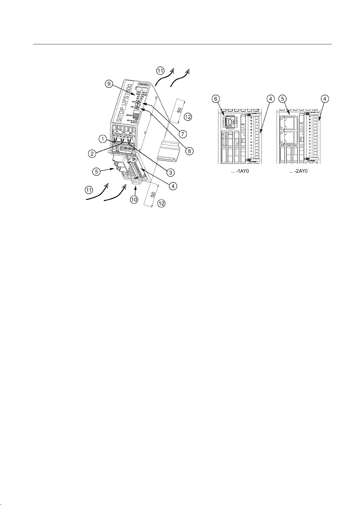
①
DC input
②
DC output
③
Bat
④
Signal connector
⑤
PROFINET (Ethernet) interface (only for ... - 2AY0)
⑥
USB interface (only for ... - 1AY0)
⑦
Rotary coding switch, switch-in threshold
⑧
Rotary coding switch, backup time
⑨
Signaling (LEDs)
⑩
DIN rail slider
⑪
Convection
⑫
Clearance above/below
2.1 Device description
Figure 2-1 UPS1600 design (example 6EP4136-3AB00-2AY0)
SITOP UPS1600 / UPS1100
Operating Instructions, 05.2014, C98130-A7628-A1-4-7629
13
Page 14
Description, device design, dimension drawing
2.1.2
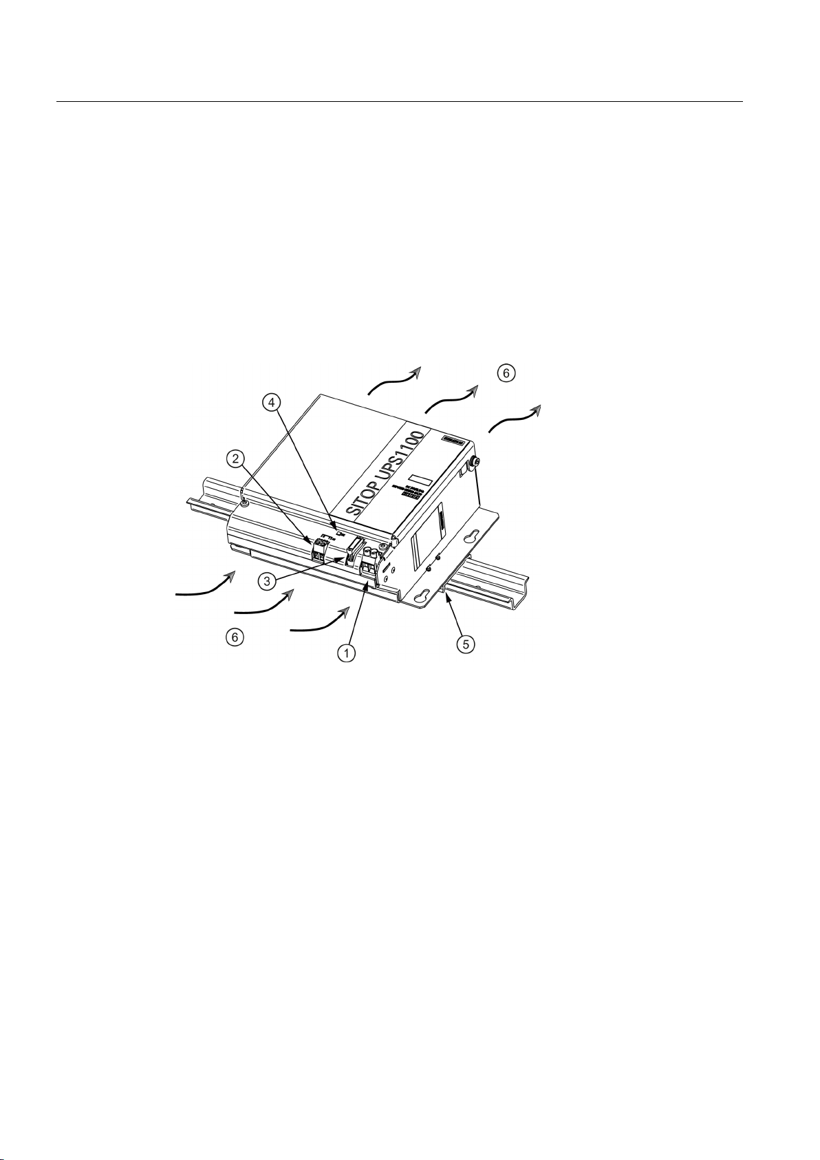
UPS1100
①
DC input X1
②
Signal terminal X2
③
Fuses F1/F2 (F2 only for 7 Ah)
④
Signaling (LED)
⑤
Top-hat mounting rail holder (not for the 7 Ah variant)
⑥
Natural convection
2.2 Connections and terminal designation
The UPS1100 battery modules consist of a battery holder with two maintenance-free, closed
lead-gel accumulators with terminals for the connection cables to the SITOP UPS1600
uninterruptible power supply. The UPS1100 contains a printed-circuit board for monitoring
the battery functions and the communication with the UPS1600. A green LED lights
continually to indicate that there is a communication connection to the UPS1600 or flashes
during the accumulator replacement.
As many as six UPS1100 of the same type can be connected in parallel with a UPS1600.
For an accumulator replacement, see Section Battery replacement (Page 112).
Figure 2-2 UPS1100 design (example 6EP4133-0GB00-0AY0)
SITOP UPS1600 / UPS1100
14 Operating Instructions, 05.2014, C98130-A7628-A1-4-7629
Page 15
Description, device design, dimension drawing
2.2
Connections and terminal designation
2.2.1
UPS1600
2.2.1.1
Power terminals
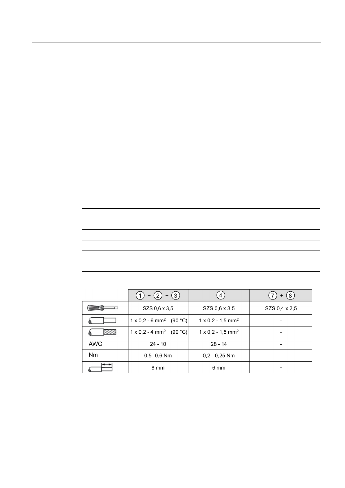
Connections and terminal designations (see Figure 2-1 UPS1600 design (example 6EP4136-3AB002AY0) (Page 13))
②
③
④
⑤
⑥
2.2 Connections and terminal designation
The input terminals ① can be used to establish the connection to the supply voltage. The
output terminals
The deployed cables must be suitable for temperatures of at least 90° C. (only for
applications for UL508)
The UPS1100 battery modules are connected via BAT
(see also Section Installation (Page 107))
① DC input IN+, IN-
DC output OUT+, OUT-
BAT+, BAT-
Signal connector
PROFINET (Ethernet) connection
USB connection
② are used to connect to the supplied loads.
③.
One screw terminal each
One screw terminal each
One screw terminal each
Connector with 14 screw terminals
RJ45 plug contact
USB-B plug contact
Figure 2-3 UPS1600 terminal data
SITOP UPS1600 / UPS1100
Operating Instructions, 05.2014, C98130-A7628-A1-4-7629
15
Page 16
Description, device design, dimension drawing
2.2.1.2
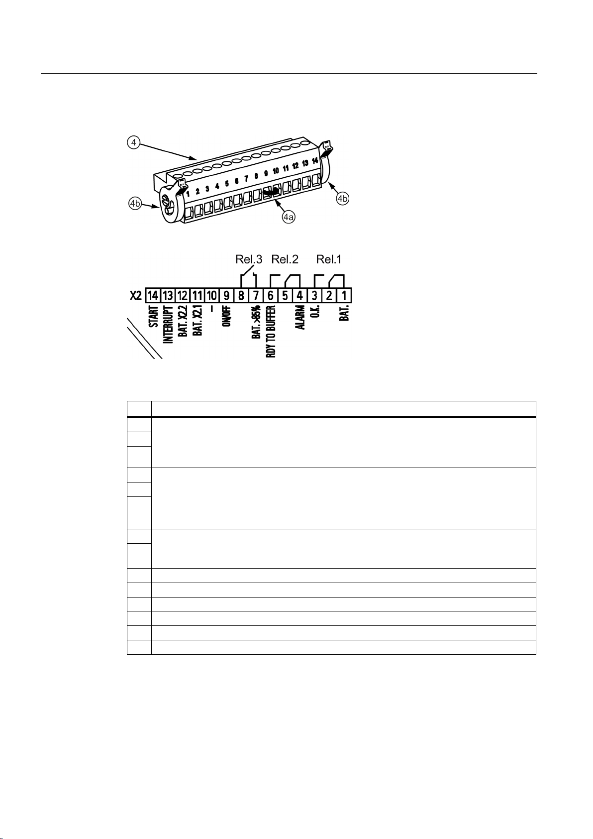
Signal terminal
Pin
Function
1
24 VDC OK / Ba
Quiescent state: Buffer mode or off
2
4
Ready for buffer operation / alarm
Cycle 0.25 Hz: Defective battery
5 6 7
Accumulator > 85%
Energized state: Buffering of the selected buffer time is possible, or charge state >85%
9
On/Off
10
Weight
11
Accumulator communication
12
Accumulator supply
13
Interrupt (reset after buffer mode)
14
Start from the battery
2.2 Connections and terminal designation
Figure 2-4 Signal connector
Figure 2-5 Signal connector connection schematic
t
REL1 (changeover contact):
Energized state: Normal operation
3
REL2 (changeover contact):
Energized state: Buffer mode is possible
Quiescent state: Not ready for buffering
REL3 (NO contact):
8
Relay contact: Maximum contact loading 30 VDC / 1 A or 125 VAC / 0.5 A
The jumper (4a) (see Figure 2-4 Signal connector (Page 16)) between pin 9 and 10 is
necessary to operate the device in buffer mode.
Delivery state: Jumper between pin 9 and 10
SITOP UPS1600 / UPS1100
16 Operating Instructions, 05.2014, C98130-A7628-A1-4-7629
Page 17

Description, device design, dimension drawing
2.2.1.3
USB port
2.2 Connections and terminal designation
Figure 2-6 USB port
The USB interface (type B) ⑥ conforms fully to the USB 2.0 standard (12 MBd). Strain relief
(see Section USB connector (Page 98)) is implemented using a defined cable/connector
(Y-Con USB - Yamaichi company).
SITOP UPS1600 / UPS1100
Operating Instructions, 05.2014, C98130-A7628-A1-4-7629
17
Page 18

Description, device design, dimension drawing
2.2.1.4
PROFINET/Ethernet connection
2.2 Connections and terminal designation
Figure 2-7 PROFINET/Ethernet connection
Ethernet interface ⑤ corresponds to the standard full duplex with up to 100 Mbit/s electrical
(100BASE-TX) according to IEEE 802.3.
Properties of the Ethernet interface:
● Transmission rate 10/100 Mbit/s
● Two RJ45 sockets, i.e. integrated switch, for RJ45 connector
● Cable type 100Base-TX (CAT5)
● Auto negotiation
● Auto crossover communication via TCP/IP and PROFINET
The strain relief (see Section PROFINET/Ethernet connector (Page 99)) is implemented
using a Siemens IE FastConnect RJ45.
The physics of the Ethernet interface is implemented so that PROFINET IO is possible in
accordance with the standards IEC 61158 and IEC 61784-2. For PROFINET, conformance
class B must be maintained as a minimum.
The Ethernet/PROFINET interface permits:
● Configuration and monitoring using the SITOP UPS Manager
● Monitoring via the Web server
● Integration and communication of the DC-UPS with other automation components from
Siemens and the open environment, e.g. IPC, PLC, HMI
● Firmware update of the device via UPS Manager or STEP 7
SITOP UPS1600 / UPS1100
18 Operating Instructions, 05.2014, C98130-A7628-A1-4-7629
Page 19
Description, device design, dimension drawing
2.2.2
UPS1100
2.2.2.1
Power terminals
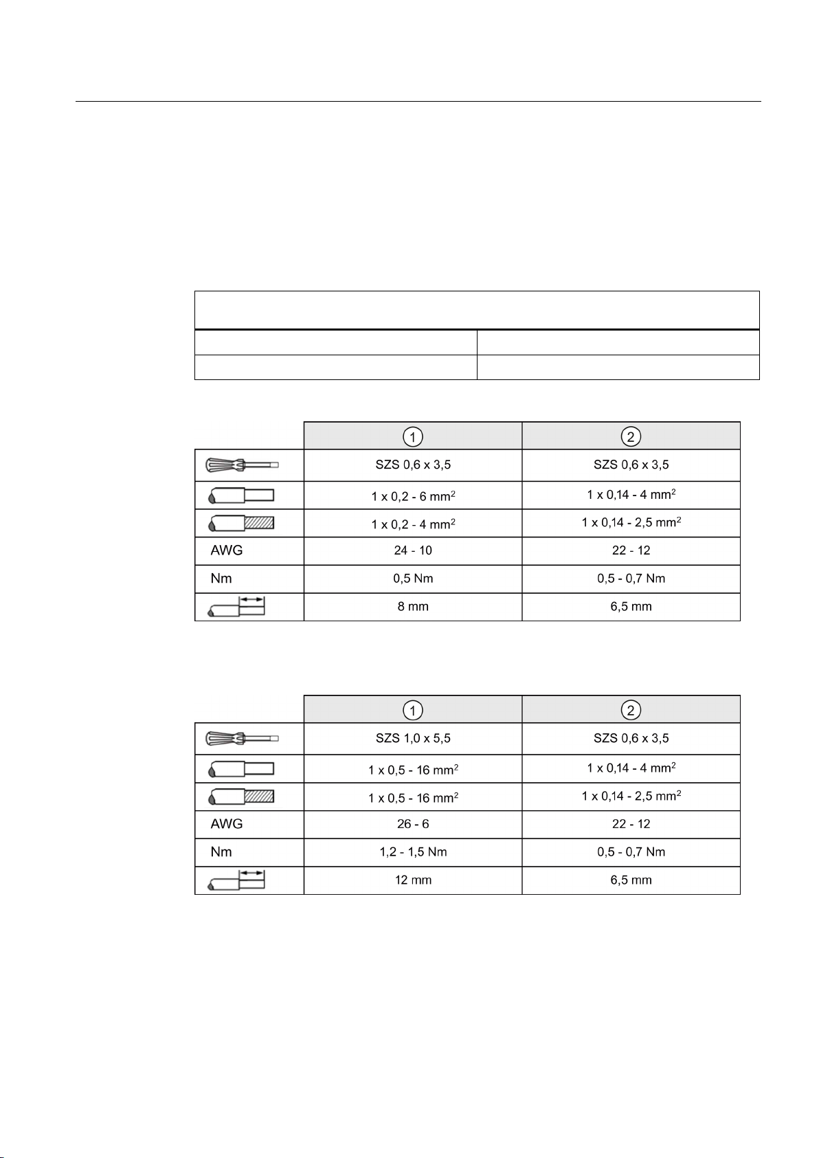
Connections and terminal designations (see Figure 2-2 UPS1100 design (example 6EP4133-0GB000AY0) (Page 14))
②
2.2 Connections and terminal designation
The input terminals ① and the signal terminal ② can be used to establish the connection to
the UPS1600 (see also Section Installation (Page 107))
① DC input +, -
Signal terminal 1, 2
One screw terminal each
One screw terminal each
Figure 2-8 Terminal data for 6EP4131-0GB00-0AY0 and 6EP4133-0GB00-0AY0
Figure 2-9 Terminal data for 6EP4134-0GB00-0AY0
SITOP UPS1600 / UPS1100
Operating Instructions, 05.2014, C98130-A7628-A1-4-7629
19
Page 20
Description, device design, dimension drawing
2.3
Switches and buttons
2.3.1
UPS1600
2.3.1.1
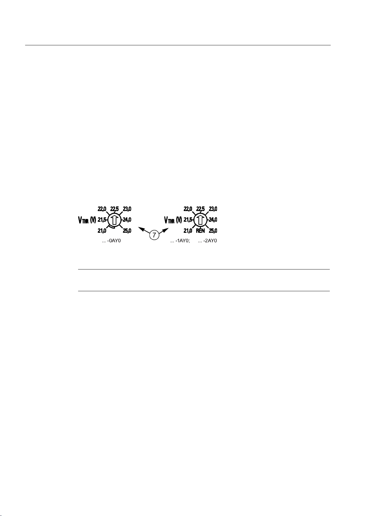
Rotary coding switch, switch-in threshold
Note
It is only permissible to actuate the rotary coding switch using an insulated screwdriver.
2.3 Switches and buttons
The switch-in threshold can be set using the rotary coding switch ⑦ on the device front
between 21.0 V and 25-0 V (21 - 21.5 - 22 - 22.5 - 23 - 24 - 25 volt). The delivery state is
22.5 V
For devices with an interface (…-1AY0, …-2AY0), the coding switch has an additional
position (REN, see the following figure). If this is selected, the software settings (for the
switch-in threshold and the backup time) apply rather than the hardware settings. In the
switch position REN, the connection X2.13 (INTERRUPT - reset after buffer operation) of the
signal terminal (see Section Signal terminal (Page 16)) has no effect.
Figure 2-10 Rotary coding switch, switch-in threshold
For notes on actuating the rotary coding switch (screwdriver, torque), see Figure 2-3
UPS1600 terminal data (Page 15).
SITOP UPS1600 / UPS1100
20 Operating Instructions, 05.2014, C98130-A7628-A1-4-7629
Page 21
Description, device design, dimension drawing
2.3.1.2
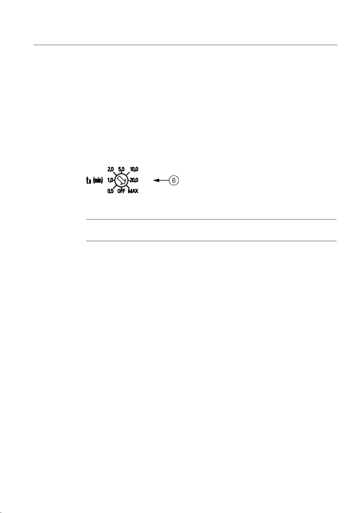
Rotary coding switch, backup time
Note
It is only permissible to actuate the rotary coding switch using an insulated screwdriver.
2.3 Switches and buttons
The backup time is set using the rotary coding switch ⑧ on the device front between
30 seconds and MAX (32767 seconds) in the steps 0.5 minute (30 seconds), 1 minute,
2 minutes, 5 minutes, 10 minutes, 20 minutes and MAX (32767 seconds). Delivery state is
MAX
The coding switch has an additional setting OFF (see following figure). If this is selected and
the additional threshold rotary coding switch is not set to REN, the buffering is disabled.
If the backup time is also set using the software (only for devices with an interface (…-1AY0,
…-2AY0)) (possible setting range, see Section Parameterizing the UPS in STEP 7 V5
(Page 61)), the rotary coding switch for the switch-in threshold (see Section Rotary coding
switch, switch-in threshold (Page 20)) must be set to REN.
Figure 2-11 Rotary coding switch, backup time
For notes on actuating the rotary coding switch (screwdriver, torque), see Figure 2-3
UPS1600 terminal data (Page 15).
SITOP UPS1600 / UPS1100
Operating Instructions, 05.2014, C98130-A7628-A1-4-7629
21
Page 22

Description, device design, dimension drawing
2.3.1.3
Jumper variants
On/Off (pin 9)
Note
The external circuit must meet the requirements relating to SELV circuits according to
EN60950
Rotary coding
switch,
buffer time
Rotary coding
switch,
connection
threshold
Wire jumper ON/OFF to ground
Result
OFF
21 - 25
Yes
Buffering not permitted
buffer time)
OFF, 0.5 - MAX
21 - 25
No
Buffering not permitted
apply
2.3 Switches and buttons
The wire jumper on the signal connector ④ between pin 9 and pin 10 (see Figure 2-4 Signal
connector (Page 16)) is used to enable/disable the buffer mode.
Buffer mode is only possible if the wire jumper ON/OFF is closed, or for UPS1600 devices
with interface, also if the rotary coding switch connection threshold is at the "REN" position.
From firmware release V1.20, the wire jumper ON/OFF has priority over the position of the
connection threshold rotary coding switch.
As a consequence, it is possible to enable or disable buffer mode using a floating contact
(e.g. a contact in the plant or system). The contact is switched instead of the ON/OFF wire
jumper. (Note: For reasons relating to noise insensitivity, approximately in the range
5...10 mA, Umax = 15 VDC, SELV: Imax = 10 mA)
-1.
Changes are also effective in the buffer mode.
Table 2- 1 With interface (up to firmware release less than V1.20)
0.5 - MAX 21 - 25 Yes Buffer mode permitted
(buffer time in
accordance with the
settings or infinite
OFF, 0.5 - MAX REN Not relevant The software settings
SITOP UPS1600 / UPS1100
22 Operating Instructions, 05.2014, C98130-A7628-A1-4-7629
Page 23

Description, device design, dimension drawing
Rotary coding
switch,
buffer time
Rotary coding
switch,
connection
threshold
Wire jumper ON/OFF to ground
Result
OFF
21 - 25
Yes
Buffering not permitted
buffer time)
OFF, 0.5 - MAX
21 - 25, REN
No
Buffering not permitted
apply
Rotary coding
switch,
buffer time
Rotary coding
switch,
connection
threshold
Wire jumper
ON/OFF to ground
Result
OFF
21 - 25
Not relevant
Buffering not permitted
infinite buffer time)
0.5 - MAX
21 - 25
No
Buffering not permitted
Interruption of the output voltage (pin 13)
Note
This function is possible only in conjunction with the R signal (DC UPS Ma
2.3 Switches and buttons
Table 2- 2 With interface (from firmware release V1.20 and higher)
0.5 - MAX 21 - 25 Yes Buffer mode permitted
(buffer time in
accordance with the
settings or infinite
OFF, 0.5 - MAX REN Yes The software settings
Table 2- 3 Without interface (all firmware releases)
0.5 - MAX 21 - 25 Yes Buffer mode permitted (buffer time
in accordance with the settings or
Delivery state: Wire jumper between pin 9 and 10
A wire jumper on the signal connector ④ between pin 13 and pin 10 is used to
enable/disable the interruption of the output voltage for the parameterized time (default value
5 seconds) for supply system restoration during the buffer time.
To prevent data losses, the PCs must be shut down timely before the buffer time ends. If the
input voltage returns after the shutdown has already started, buffer mode is ended and the
UPS1600 goes into normal operation. The PC will be shut down, however, it is not switched
off. PCs, which do not have an on/off switch, can only be rebooted by switching off the power
and switching on again.
For customers that use their own software, this pulse must be selected at the DC UPS
module.
nager).
SITOP UPS1600 / UPS1100
Operating Instructions, 05.2014, C98130-A7628-A1-4-7629
23
Page 24

Description, device design, dimension drawing
Start from the battery (pin 14)
Charge current setting (pin 10 / 11 / 12)
UPS1600 10 A
UPS1600 20 A
Terminal X2.11
Terminal X2.12
0.3 A
0.8 A
open
open
0.8 A
1.75 A
open
connected with X2.10
Max.
Max.
connected with X2.10
open
2.3 Switches and buttons
The start from the battery is initiated by closing the contact pin 14 to ground (pin 10). This
jumper must not provide a permanent connection, but must be controlled using a button. The
input is designed so that a single lamp with a permissible supply voltage of between 12 and
30 V and 8 to 15 mA can be switched in series to the switching contact. If while pressing the
button, the UPS1600 enters buffer mode, the set buffer time will be started. For example, if
5 minutes is set, the UPS1600 sets itself off after 5 minutes. If the input voltage returns
during the buffer time, the UPS1600 switches to normal operation.
If the input voltage is available, the DC UPS starts in the normal operation.
If the UPS1600 is switched-off remotely via the interface (also possible when input voltage is
available), start from the battery can be used to restart the UPS1600.
For uncoded batteries, the size of the charge current can be changed by placing jumpers
between the terminals X2.10 (ground) and X2.11 or X2.12.
Table 2- 4 Charge current
SITOP UPS1600 / UPS1100
24 Operating Instructions, 05.2014, C98130-A7628-A1-4-7629
Page 25
Description, device design, dimension drawing
2.3.2
UPS1100
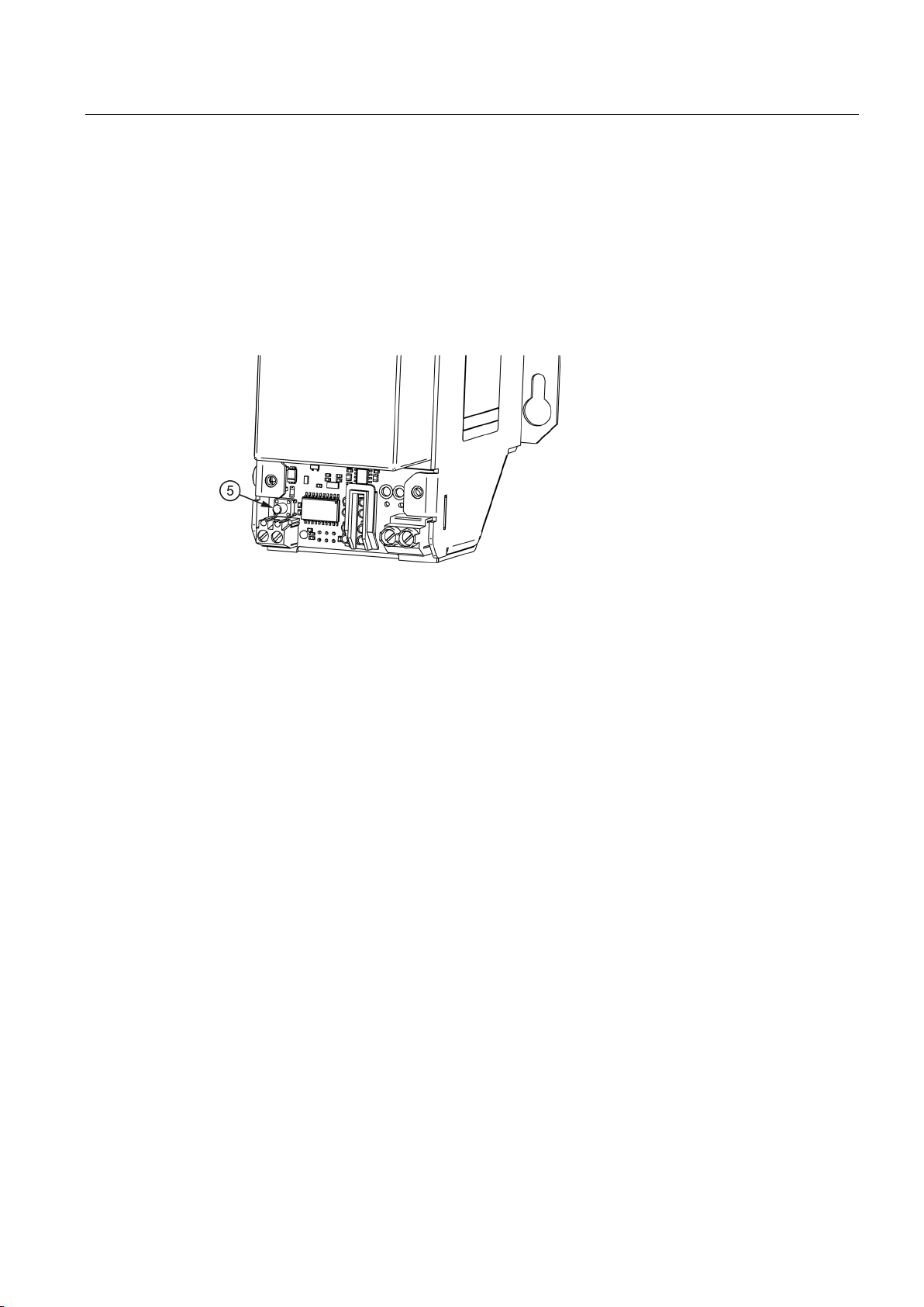
2.3.2.1
Buttons for battery replacement
2.3 Switches and buttons
For the UPS1100, a button ⑤ for the battery replacement is located under the cover.
Battery replacement, see Section Battery replacement (Page 112)
Figure 2-12 Buttons for battery replacement
SITOP UPS1600 / UPS1100
Operating Instructions, 05.2014, C98130-A7628-A1-4-7629
25
Page 26
Description, device design, dimension drawing
2.4
Operating displays and signaling
2.4.1
UPS1600
2.4.1.1
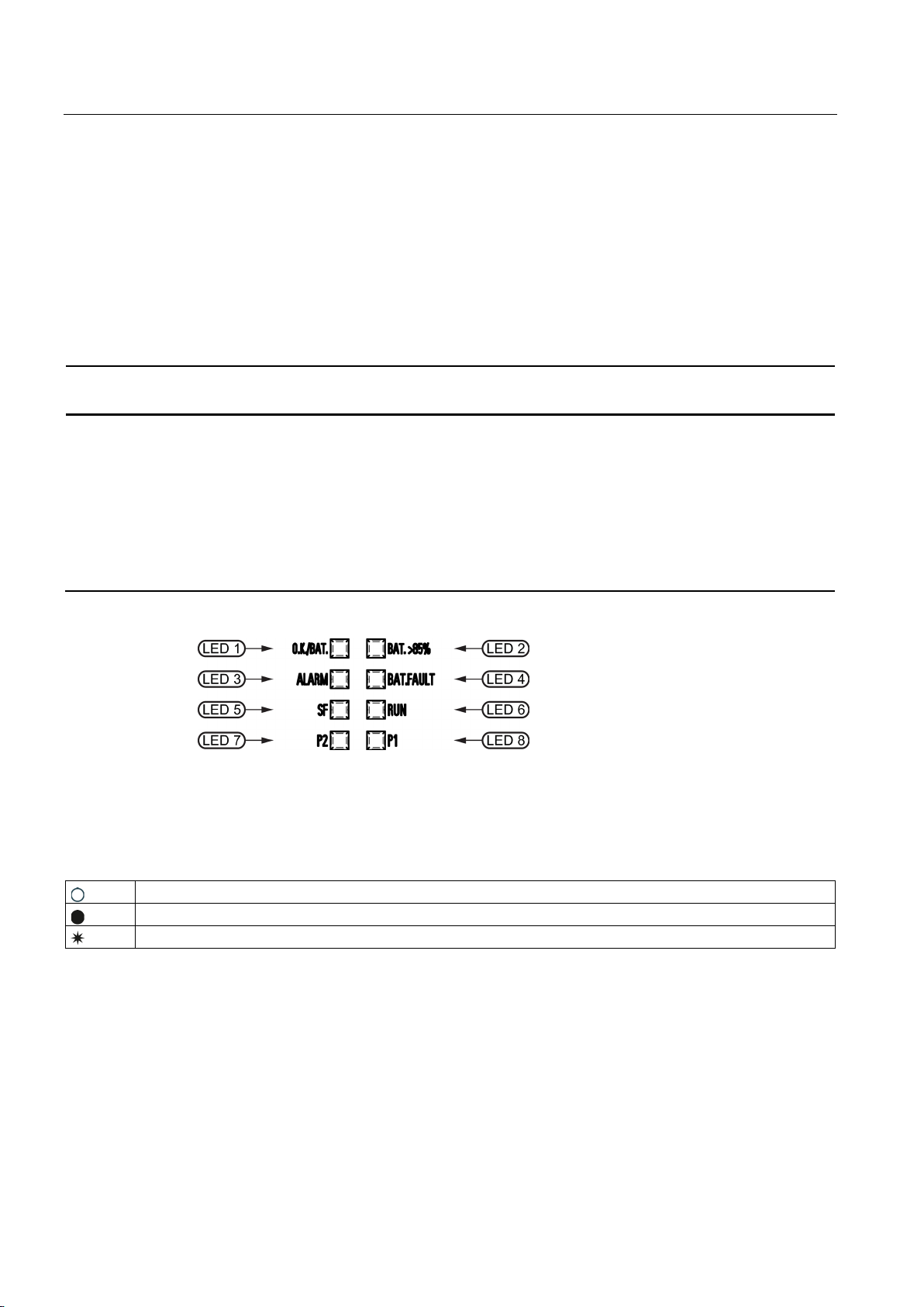
LEDs
6EP4134-3AB00-...
6EP4136-3AB00-...
LED 7 and 8 are active only for ... -2AY0
Legend:
LED off
LED lights up
0,5/3
LED flashes on in 0.5-second and off in 3-second intervals
2.4 Operating displays and signaling
Status display LED1: DC-UPS operating mode
LED2: Charge state
LED3: Ready for buffering
LED4: Accumulator test
LED5: Specific diagnostic displays for PROFINET
LED6: Specific diagnostic displays for PROFINET
LED7: Ethernet port 1 connection state
LED8: Ethernet port 2 connection state
Figure 2-13 Operating displays
SITOP UPS1600 / UPS1100
26 Operating Instructions, 05.2014, C98130-A7628-A1-4-7629
Page 27
Description, device design, dimension drawing
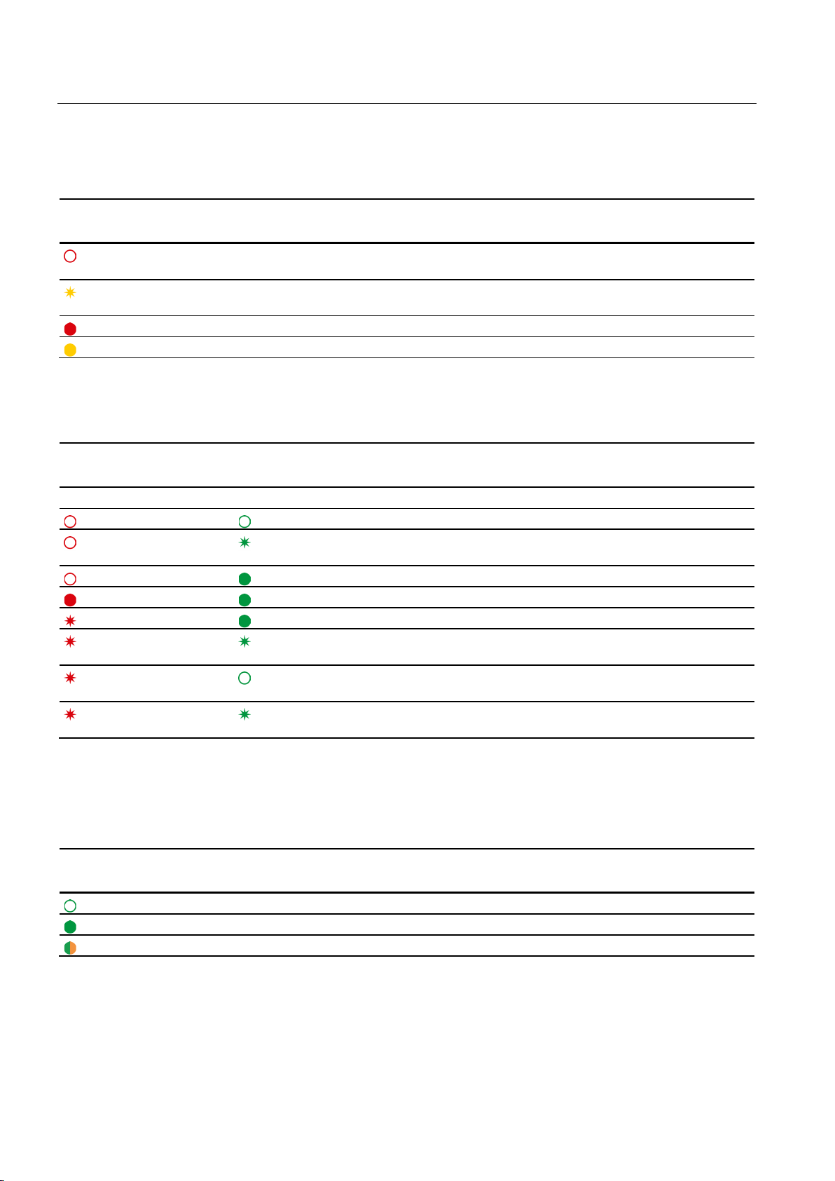
LED 1 (OK/Bat)
Signaling
6EP4134-3AB00-...
6EP4136-3AB00-...
Off
DC-UPS off
Red
DC-UPS defect (severe hardware fault)
Flashing red (0.5/0.5)
Firmware update
Flashing red (1/1)
Software corrupted
(0.5/0.5)
Flashing yellow (0.5/3)
Buffer mode, output off
Yellow
Buffer mode
Flashing green (0.5/3)
DC-UPS OK, output off
Green
DC-UPS OK
LED 2 (Bat. > 85%)
Signaling
6EP4134-3AB00-...
6EP4136-3AB00-...
(0.5/0.5)
Off
Battery charge state < 85%
Green
Battery charge state > 85%
LED 3 (alarm)
Signaling
6EP4134-3AB00-...
6EP4136-3AB00-...
possible
Off
Buffer operation possible
2.4 Operating displays and signaling
Flashing yellow
Flashing green
Critical temperature reached, overtemperature or overvoltage at the input
Updating the firmware
Red Output off for 45 seconds because of overcurrent, overtemperature or buffer operation not
SITOP UPS1600 / UPS1100
Operating Instructions, 05.2014, C98130-A7628-A1-4-7629
27
Page 28
Description, device design, dimension drawing
LED 4 (accumulator / bat. fault)
Signaling
6EP4134-3AB00-...
6EP4136-3AB00-...
position MAX
(0.5/0.5)
Red
Battery defective
Yellow
Selected backup time cannot be attained
LED 5 and LED 6 (PROFINET LEDs)
Signaling
6EP4134-3AB00-2AY0
6EP4136-3AB00-2AY0
LED 5 (SF)
LED 6 (RUN)
Off Off
No connection to a PROFINET IO controller
(0.5/0.5)
Off Green
Application started successfully, module OK
Red Green
Application started successfully, module not OK
Flashing red (0,1/0,1)
Green
Application in progress, diagnosis can be called
(0.5/0.5)
LED 7 (Ethernet LED / P2)
Signaling
6EP4134-3AB00-2AY0
6EP4136-3AB00-2AY0
Off
Device not connected with controller
Green
Device connected with controller, no activity
Green/orange alternately
Device connected with controller, send/receive data (RX/TX)
2.4 Operating displays and signaling
Off Battery OK or uncoded battery modules connected or backup time rotary coding switch at
Flashing yellow
Off
Flashing red (0.5/0.5)
Flashing red (0.5/0.5)
Flashing red (0.5/0.5)
Battery outside the permitted temperature range
Flashing green
Flashing green
Off DCP requires device identification (LED flashes for
Flashing green
(0.5/0.5)
Configuration by the PROFINET IO controller
Self-test in progress (flashing alternately every 3 seconds)
3 seconds)
Updating the firmware
LED 5 and 6 are active only for ... -2AY0
LED 7 is active only for ... -2AY0
SITOP UPS1600 / UPS1100
28 Operating Instructions, 05.2014, C98130-A7628-A1-4-7629
Page 29
Description, device design, dimension drawing
LED 8 (Ethernet LED / P1)
Signaling
6EP4134-3AB00-2AY0
6EP4136-3AB00-2AY0
Off
Device not connected with controller
Green
Device connected with controller, no activity
Green/orange alternately
Device connected with controller, send/receive data (RX/TX)
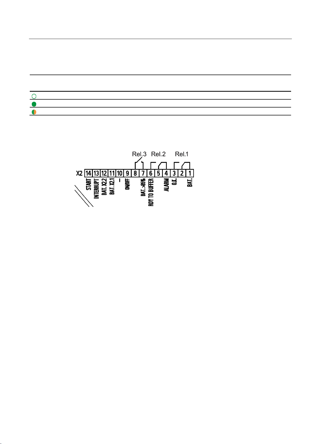
2.4.1.2
Relay outputs
REL1 (changeover contact):
REL2 (changeover contact):
REL3 (NO contact):
2.4 Operating displays and signaling
LED 8 is active only for ... -2AY0
Figure 2-14 Signal connector connection schematic
Energized state: Normal operation
Quiescent state: Buffer mode or off
Energized state: Buffer operation is possible
Quiescent state: Not ready for buffering
Cycle 0.25 Hz: Accumulator defective or set backup time is not attained
Energized state: Buffering of the selected backup time is possible, or charge state >85%
SITOP UPS1600 / UPS1100
Operating Instructions, 05.2014, C98130-A7628-A1-4-7629
29
Page 30
Description, device design, dimension drawing
2.4.2
UPS1100
2.4.2.1
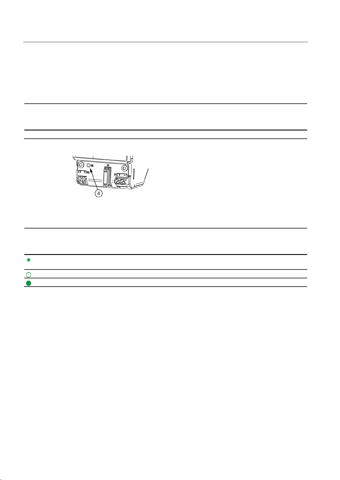
LEDs
6EP4131-0GB00-0AY0 (1.2 Ah)
6EP4133-0GB00-0AY0 (3.2 Ah)
6EP4134-0GB00-0AY0 (7 Ah)
Status display
LED battery
Signaling
6EP4131-0GB00-0AY0 (1.2 Ah)
6EP4133-0GB00-0AY0 (3.2 Ah)
6EP4134-0GB00-0AY0 (7 Ah)
(0.5/0.5)
Off
Battery off, no communication
Green
Battery OK
2.4 Operating displays and signaling
Table 2- 5 LED
Figure 2-15 6EP4131-0GB00-0AY0 example
④ battery
Flashing green
Fault or alarm
SITOP UPS1600 / UPS1100
30 Operating Instructions, 05.2014, C98130-A7628-A1-4-7629
Page 31

Description, device design, dimension drawing
2.5
Block diagram
2.5.1
UPS1600
2.5 Block diagram
Figure 2-16 UPS1600 block diagram
SITOP UPS1600 / UPS1100
Operating Instructions, 05.2014, C98130-A7628-A1-4-7629
31
Page 32

Description, device design, dimension drawing
2.5.2
UPS1100
2.6 Dimensions and weight
Figure 2-17 UPS1100 block diagram
SITOP UPS1600 / UPS1100
32 Operating Instructions, 05.2014, C98130-A7628-A1-4-7629
Page 33

Description, device design, dimension drawing
2.6
Dimensions and weight
2.6.1
UPS1600
2.6 Dimensions and weight
Figure 2-18 6EP4134-3AB00-0AY0, 6EP4134-3AB00-1AY0, 6EP4136-3AB00-0AY0,6EP4136-
3AB00-1AY0 dimensioned drawing
Figure 2-19 6EP4134-3AB00-2AY0, 6EP4136-3AB00-2AY0 dimensioned drawing
SITOP UPS1600 / UPS1100
Operating Instructions, 05.2014, C98130-A7628-A1-4-7629
33
Page 34

Description, device design, dimension drawing
6EP4134-3AB00-0AY0
6EP4134-3AB00-1AY0
6EP4134-3AB00-2AY0
in mm
Weight
Approx. 0.38 kg
Approx. 0.4 kg
Approx. 0.45 kg
6EP4136-3AB00-0AY0
6EP4136-3AB00-1AY0
6EP4136-3AB00-2AY0
in mm
Weight
Approx. 0.39 kg
Approx. 0.41 kg
Approx. 0.45 kg
2.6 Dimensions and weight
Dimensions (W × H × D)
Dimensions (W × H × D)
50 × 138.7 × 125 50 × 138.7 × 125 50 × 138.7 × 125
50 × 138.7 × 125 50 × 138.7 × 125 50 × 138.7 × 125
SITOP UPS1600 / UPS1100
34 Operating Instructions, 05.2014, C98130-A7628-A1-4-7629
Page 35

Description, device design, dimension drawing
2.6.2
UPS1100
2.6 Dimensions and weight
Figure 2-20 6EP4131-0GB00-0AY0 dimensioned drawing
Figure 2-21 6EP4133-0GB00-0AY0 dimensioned drawing
SITOP UPS1600 / UPS1100
Operating Instructions, 05.2014, C98130-A7628-A1-4-7629
35
Page 36

Description, device design, dimension drawing
6EP4131-0GB00-0AY0
(1.2 Ah)
6EP4133-0GB00-0AY0
(3.2 Ah)
6EP4134-0GB00-0AY0
(7 Ah)
in mm
Weight
Approx. 1.9 kg
Approx. 3.8 kg
Approx. 6.1 kg
2.6 Dimensions and weight
Figure 2-22 6EP4134-0GB00-0AY0 dimensioned drawing
Dimensions (W × H × D)
89 × 130 × 107 190 × 169 × 79 186 × 186 × 110
SITOP UPS1600 / UPS1100
36 Operating Instructions, 05.2014, C98130-A7628-A1-4-7629
Page 37

3
3.1
General information
Contents of the "Engineering" section
Functions of the individual software products
STEP 7 in the TIA Portal
STEP 7 V5
SITOP UPS Manager
Web server
Note
SITOP UPS Manager and TIA cannot simultaneously access the UPS1600.
This section describes those software tools offered by Siemens that are compatible with
SITOP UPS1600 . The software tools are introduced with their functions, the associated
requirements and the operation. The software products are:
● STEP 7 in the TIA Portal from V12
● STEP 7 V5.4 or higher
● SITOP UPS Manager
● Web server
●
The UPS1600 can be used with STEP 7 in the TIA Portal from Version 12 with service
pack 1 (SP1).
As the UPS1600 has been saved in the hardware catalog of STEP 7 in the TIA Portal , it
can be integrated in the project, parameterized and diagnosed.
●
The UPS1600 can be used with STEP 7 V5 from Version 5.4.
As UPS1600 has been saved in the hardware catalog of STEP 7 V5 it can be integrated
in the project, parameterized and diagnosed.
●
UPS1600 can be parameterized with SITOP UPS Manager . In addition, the protection of
individual computers or computer networks can be determined by shutdown conditions
after the failure of the supply voltage.
●
The web server can be used to check the parameters and diagnose the UPS1600.
SITOP UPS1600 / UPS1100
Operating Instructions, 05.2014, C98130-A7628-A1-4-7629
37
Page 38

Engineering
3.2
Alarm list
Error
Type
Extended
Error Type
Maintenance
Alarm Text
Help Text
256 - F
Device failure
Device failure
256 1 MR
Corrupt software
Software is corrupt - try to update the software
256 2 MR
Wrong checksum
Internal error: Communication disrupted
object.
DC UPS.
256 5 MR
Wrong message length
Internal error: Communication disrupted
256 6 MR
Wrong parameter
Parameter value is not within the specified range
256 7 MR
Command not accepted
An incorrect command was sent to the DC UPS
length field
256 9 MR
Wrong request
Error in sent message: Unknown request sent.
256
10
MR
Cannot write to object
Attempting to write a parameter that is "read-only"
object.
was interrupted.
defective.
command.
256
15
MR
Command outside range
An incorrect command was sent to the DC UPS
executed
the program is running.
software update has been started.
does not exist or is not connected.
update file is corrupt.
256
20
MR
Write error
Cannot write to Flash - hardware may be defective
256
21
MR
Read error
Unable to read EEPROM. Device is defective.
3.2 Alarm list
The help text provides further information about a pending alarm.
The Extended Error Type helps to interpret the alarms in self-programmed S7 function
blocks.
The maintenance specifies the severity of the alarm:
MR = Maintenance Required
MD = Maintenance Demanded
F = Failure
256 3 MR Parameter corrupt Attempting to write to an unknown or read-only
256 4 MR Unknown parameter Attempting to set a parameter that is not known by
256 8 MR Communication error: Wrong
256 11 MR Object pending DC UPS cannot provide data for the requested
256 12 MR Battery not available Attempting to access a battery that is not available.
256 13 MR EEPROM write error Saving DC UPS parameters failed. Device is
256 14 MR Unknown alarm Internal error: Wrong parameter at execution of test
256 16 MR SW update is currently being
256 17 MR No software update Cannot execute the sent command because no
256 18 MR Wrong battery number Attempting to retrieve data about a battery which
256 19 MR Wrong address Wrong Flash address in software update - software
Syntax error in command
Either the battery with the requested number was
never connected or communication with this battery
The command sent cannot be executed as long as
SITOP UPS1600 / UPS1100
38 Operating Instructions, 05.2014, C98130-A7628-A1-4-7629
Page 39

Engineering
Error
Type
Extended
Error Type
Maintenance
Alarm Text
Help Text
an update file that is not suitable for the DC UPS.
software again
an invalid update file. The update file is probably too
old.
An entry in the software update cannot contain more
than 32 bytes of reference data.
256
26
F
Device failure
Device failure
257 - F
Device diagnostics
Device diagnostics
cabling, fuse, and battery voltages
be exceeded!
to battery
battery power cable
interrupted
check connection
and fuse
Battery is defective or not supported by SIEMENS.
again after 20s.
257 8 MR
Reset buffer timer
The PC shuts down
PC has been shut down
overtemperature, excessive output current).
an error situation.
time.
257
13
MR
Reserve
is operational again.
operational.
257
16
MD
Surplus battery
More than 6 batteries connected
3.2 Alarm list
256 22 MR Wrong device ID An attempt was made to update the software with
256 23 MR Corrupt data record Error during software update - try to update the
256 24 MR Wrong update An attempt was made to update the software with
256 25 MR Too much data
257 1 MD Buffer mode is not possible Buffer mode is not possible - check settings,
257 2 MD Device temperature critical
(too high)
257 3 MD Device temperature critical
(too low)
257 4 F High-resistance connection
257 5 F Connection to battery
257 6 MD Unknown battery Data from the battery cannot be read correctly.
257 7 MR Overcurrent Output current of DC UPS is too high. Output will be
257 9 MR DC UPS switched off DC UPS switched off - buffer time exceeded or the
257 10 MR Output switched off The DC UPS output was shut down as result of
257 11 MR Output switched on The DC UPS output was switched on again as
257 12 MR Reset performed Input voltage to DC UPS was OK again before the
Internal device temperature close to the upper limit.
Caution: The highest permitted temperature could
Internal device temperature close to the lower limit.
Device could leave the operating range.
High-resistance connection to battery - check
Connection to battery interrupted -
switched off for 20s. The output will be switched on
executing an instruction or an error situation (e.g.
result of executing an instruction or the correction of
buffer time expired. Connected devices are reset by
switching off the DC UPS outputs for the configured
257 14 MR Software update successful Previous software update was successful - DC UPS
257 15 MR Input voltage is too high Input voltage exceeds 30 V. DC UPS is not
SITOP UPS1600 / UPS1100
Operating Instructions, 05.2014, C98130-A7628-A1-4-7629
39
Page 40

Engineering
Error
Type
Extended
Error Type
Maintenance
Alarm Text
Help Text
software
prevent damage to the device.
257
19
MR
Reserve
operational.
257
21
MR
Buffering
Device is in buffer mode
failed
defective
257
23
MR
Device powered up
Device powered up
257
24
F
Wrong battery polarity
Wrong battery polarity - check battery connections.
257
25
MD
Reserve
configured buffer time.
257
27
MR
Deep discharge battery
Battery is deep discharged - no buffering possible
258 - F
Battery diagnostics
Battery diagnostics
index: {1:d})
(battery index: {1:d})
shortened
(battery index: {1:d})
current
fault (battery index: {1:d})
longer possible - check communication
the charge parameters.
(battery index: {1:d})
the same type can be operated together.
(battery index: {1:d})
(battery index: {1:d})
{1:d})
3.2 Alarm list
257 17 F DC UPS parameters corrupt DC UPS parameters corrupt - try to update the
257 18 F Device overtemperature Output and battery charging is switched off to
257 20 MR Low voltage mode Input voltage of DC UPS is too low. DC UPS is not
257 22 MD Communication with device
257 26 MR Insufficient charge level The battery charge level is too low to guarantee the
258 1 F Battery defective (battery
index: {1:d})
258 2 F Deep discharge battery, no
charging possible (battery
258 3 MD Battery temperature high
258 4 MD Battery temperature low
258 5 F Communication with battery
258 6 MR New battery detected
(battery index: {1:d})
PROFINET connection available - DC UPS is
Battery defective - check the fuse and the battery
voltages
Battery is deep discharged - replace battery
Battery temperature too high - battery life will be
Battery temperature too low - reduced output
Communication with formerly known battery is no
A new battery was connected. The battery will be
included in the calculation of the total capacity and
258 7 F Wrong battery configuration
258 8 MD Battery parameters corrupt
258 9 MR Battery replacement started
258 10 MR Battery replacement finished
258 11 MD Battery replacement
SITOP UPS1600 / UPS1100
40 Operating Instructions, 05.2014, C98130-A7628-A1-4-7629
(battery index: {1:d})
canceled (battery index:
Different battery types connected. Only batteries of
Battery defective - replace battery
Battery replacement started by user
Battery replacement finished - counters have been
reset
Battery replacement canceled - battery parameters
are not reset
Page 41

Engineering
3.3
STEP 7 in the TIA-Portal
Note
TIA and UPS Manager cannot simultaneously access the UPS. It is not permissible that UPS
Managers service runs whileTIA is being accessed.
3.3.1
Installing the Hardware Support Package
Procedure
Note
You can find additional information on installing hardware support packages in the STEP 7
manual in the TIA Portal.
3.3 STEP 7 in the TIA-Portal
The UPS1600 can be used with STEP 7 in the TIA Portal from version 12 with service pack
1 (SP1).
In STEP 7 in the TIA Portal the UPS1600 can be integrated, parameterized and diagnosed in
projects.
To use the UPS1600, you must install the corresponding hardware support package (HSP)
in the TIA-Portal . We make this HSP available to you on our SITOP homepage
(http://www.siemens.de/sitop-usv) or directly under
(http://support.automation.siemens.com/WW/view/de/75854606).
To install the Hardware Support Package, proceed as follows:
1. Start STEP 7 in the TIA Portal as administrator.
2. Click in the menu "Tools" on "Support Packages".
The "Detailed information" dialog opens. All Support Packages from the directory that you
specified as storage location for Support Packages in the settings are listed in a table.
3. You have the following possibilities to install the Hardware Support Package:
– If the Support Package is already present on your computer or on the supplied DVD,
you can add it to the list from the "Add from the file system".
– If you want to add a Support Package from the "Service & Support" page in the
Internet, first download it with "Load from the Internet".
You can then add it to the file system.
4. Select the Support Package that you want to install.
5. Click on "Install", and follow the instructions of the installation program.
6. Exit the TIA-Portal and then restart it.
SITOP UPS1600 / UPS1100
Operating Instructions, 05.2014, C98130-A7628-A1-4-7629
41
Page 42

Engineering
3.3.2
Integrating UPS1600 into a project
Note
Additional information
provided in the STEP 7 manual in the TIA Portal.
Preconditions
Inserting UPS1600 from the hardware catalog
3.3 STEP 7 in the TIA-Portal
To be able to use UPS1600, it must be assigned to an IO controller as an IO device. Further,
UPS1600 can be equipped in the project with one or several UPS1100 battery modules.
The main views for the configuration of the UPS1600 are the network view and the device
view.
on the network view and device view as well as the topology view is
● The hardware support package of UPS1600 has been correctly installed.
● STEP 7 in the TIA-Portal has been opened, and a project has been created with an IO
controller .
1. Open the network view.
2. Open the "Hardware catalog" task card.
3. In the "Catalog" palette navigate to the UPS1600 under Power supplies\SITOP
UPS\UPS1600.
4. Select the required UPS1600 using a mouse click.
In the "Information" area you can see information about the selected UPS1600.
5. Drag the UPS1600 and drop it into the Network view.
You have now placed the UPS1600 in the Network view. The rectangle displayed
symbolizes the UPS1600.
SITOP UPS1600 / UPS1100
42 Operating Instructions, 05.2014, C98130-A7628-A1-4-7629
Page 43

Engineering
Assigning the UPS1600 a controller
3.3 STEP 7 in the TIA-Portal
To be able to use UPS1600, it must be assigned to an IO controller as an IO device.
1. Click in the network view on the blue lettering "Not assigned" at the left next to the symbol
of the UPS1600.
A menu opens with the available controllers.
2. Select a controller in the menu.
3. Select the connection between the controller and UPS1600.
4. Make the required settings in the "Network data".
5. Double-click on UPS1600, to display it in the device view.
SITOP UPS1600 / UPS1100
Operating Instructions, 05.2014, C98130-A7628-A1-4-7629
43
Page 44

Engineering
3.3.3
Assigning the UPS1600 battery modules
Note
Only UPS1100 battery modules of the same type can be inserted into the slots of a
UPS1600.
The number of UPS1100 battery modules that can be
Preconditions
Procedure
3.3 STEP 7 in the TIA-Portal
6. Select the PROFINET-interface.
7. Under "Ethernet addresses" in the inspector window enter the IP address of the
UPS1600, which was already assigned in the TIA-Portal .
You have assigned the UPS1600 a controller.
The basic functions of the uninterruptible power supply are available with all of the battery
modules that are compatible with the UPS1600.
Additional functions are available with the UPS1100 battery module:
● Automatic detection of the battery module rated values
● Automatic management of up to 6 battery modules
● Temperature-controlled charging
● Battery fast test
● Diagnostics using SITOP UPS Manager and the web server
Using an example, in the following steps it is shown how a UPS1100 battery module is
assigned to the UPS1600.
configured is limited to 6.
● STEP 7 in the TIA-Portal has been opened and a project has been created.
● A UPS1600 has been integrated in the project.
1. In the device view, select the UPS1600.
2. In the Hardware catalog , navigate to the UPS1100 battery module under Power
supplies\SITOP UPS\UPS1600.
3. Select the required UPS1100 battery module in the hardware catalog.
SITOP UPS1600 / UPS1100
44 Operating Instructions, 05.2014, C98130-A7628-A1-4-7629
Page 45

Engineering
3.3 STEP 7 in the TIA-Portal
4. Drag the UPS1100 battery module and drop it into the Device view.
Alternatively, the UPS1100 battery module can be added by double-clicking on the entry
in the hardware catalog.
5. Drag the UPS1100 battery module and drop at the first free slot to the right next to the
UPS1600.
The UPS1100 battery module is inserted at the selected slot.
6. Save the hardware configuration.
Section Parameterizing UPS1600 with STEP 7 in the TIA Portal (Page 46) describes how
you can change the number and type of UPS1100 battery module used.
SITOP UPS1600 / UPS1100
Operating Instructions, 05.2014, C98130-A7628-A1-4-7629
45
Page 46

Engineering
3.3.4
UPS1600 and UPS1100 parameters in Step 7 in the TIA Portal
Tab
Subgroup
Description
Buffering
All parameters that affect the behavior of the UPS for buffering.
Signaling
Setting of the alarm signaling and the wait time for stable input voltage.
intervals
Energy storage
–
Parameters for the deployed battery modules.
(yes/no).
3.3.5
Parameterizing the UPS in STEP 7 in the TIA Portal
Preconditions
3.3 STEP 7 in the TIA-Portal
The adjustable parameters of the UPS1600 and the UPS1100 battery modules used can be
found in STEP 7 in the TIA Portal in theInspector window under Properties if the
corresponding device was selected. The "Basic device", "Energy storage" and "Web server"
parameters are relevant. These tabs and their subgroups are shown in the table below.
Basic unit
Battery maintenance
Web server General information Specification whether access to the UPS via Web server is permitted
Maintenance interval for the deployed batteries.
A detailed description of the individual parameters of the subgroups is contained in the
associated section under Parameterizing the UPS in STEP 7 in the TIA Portal (Page 46).
The procedure is the same for all parameters. This section describes the general procedure
to reach the configuration dialog. The individual parameters and their possible values are
described in the following subsections.
Each parameter has a start value. A click on "Reset to initial values" resets all parameters of
a subgroup to the associated start value.
● The UPS1600 was integrated in the project that has been opened
SITOP UPS1600 / UPS1100
46 Operating Instructions, 05.2014, C98130-A7628-A1-4-7629
Page 47

Engineering
Proceed as follows
Buffering parameters
Parameter
Value range
Default setting
Buffering allowed
Yes / No
Yes
Connection threshold
21 … 25 V
21.5 V
Buffer time
1 … 32767 s
60 s
Additional buffer time after PC shutdown
1 … 300 s
10 s
Stop buffering voltage
18 … 23 V
18.5 V
Interruption time
1 … 120 s
5 s
Buffering allowed
Connection threshold
Buffer time
Additional buffer time after PC shutdown
Stop buffering voltage
3.3 STEP 7 in the TIA-Portal
1. Select the UPS1600.
2. In the Inspector window open tab "Properties/General"
You see the possible subtabs for the parameterization.
Activate interruption of the output voltage for supply system
restoration
●
Select between buffers with the specified values or passive measurement of the power
supply by the UPS.
●
If the connection threshold value is undershot, the UPS starts buffering. If the value of the
connection threshold is reached or undershot again later, the UPS stops buffering.
●
The time to be buffered by the UPS. The "Buffering allowed" parameter is used to specify
whether buffering should be performed.
Yes / No Yes
●
Time, to be buffered by the UPS1600 after the PC has been shut down.
●
The voltage at which battery discharge is terminated.
SITOP UPS1600 / UPS1100
Operating Instructions, 05.2014, C98130-A7628-A1-4-7629
47
Page 48

Engineering
Activate interruption of the output voltage for supply system restoration
Interruption time
Signaling
Parameter
Value range
Default setting
Downtime alarm
0 … 20,000 ms
125 ms
Wait time for stable input voltage
0.005 … 65 s
0.5 s
Signaling delay for supply system failure
Signaling delay for supply system restoration
Energy storage
Possible parameters when using a UPS1100 battery module
Parameter
Value range
Module
Drop-down menu with the UPS1100 battery modules saved by the HSP
Number of modules
0 … 6
Total capacity
0 … 42 Ah
Module
Number of modules
Total capacity
3.3 STEP 7 in the TIA-Portal
●
If the value is set to "Yes", the system enters a reset after a supply system restoration
during the buffering and switches the output off for a defined time (interruption time). This
option is useful, when, for example, computer networks are protected by the UPS that
can be activated by a reset when the power supply is restored.
●
The interruption time after which the power returns during buffer mode.
●
The time that a fault must be present before a response is made (buffering message).
●
The wait time until a stable input voltage is present.
The "energy storage" has two different areas that depend on the battery type being used.
First select whether you are using a UPS1100 battery module or some other energy storage
device.
●
Type of UPS1100 battery module.
●
Number of the installed modules.
●
Total capacity of the installed battery modules.
SITOP UPS1600 / UPS1100
48 Operating Instructions, 05.2014, C98130-A7628-A1-4-7629
Page 49

Engineering
Possible parameters for the deployment of a different battery module
Parameter
Value range
Default setting
Total capacity
0.1 … 3,200 Ah
10 Ah
End-of-charge voltage
24 … 30 V
27.3 V
Charge current
0.001 … 4 A
0.8 A
Faulty battery voltage
1 … 18 V
6 V
Total capacity
End-of-charge voltage
Charge current
Faulty battery voltage
Web server
Parameter
Value range
Default setting
Activate the Web server on this module
Yes / No
Yes
3.3.6
Configuring the UPS1600 in the system
Identifying a UPS1600 in the system
3.3 STEP 7 in the TIA-Portal
●
Total capacity of the installed batteries.
●
The charging completes when the selected end-of-charge voltage is reached.
●
The battery is not charged with more than the selected charge current. The
manufacturer's details for the permitted charge current of the battery must be observed. If
several batteries are connected, the lowest permitted charge current applies.
The following device-dependent maximum values also apply:
– SITOP UPS1600 20A: Maximum permissible charge current 4000 mA
– SITOP UPS1600 10A: Maximum permissible charge current 3000 mA
●
If the battery voltage undershoots this value, it is considered as being faulty by the
UPS1600 and not charged.
Set here whether access to the UPS via Web server is permitted.
In the delivered state, the UPS1600 has not yet been assigned any IP address and the
DHCP protocol is deactivated.
When the UPS1600 is first connected with a controller, it must be assigned a device name
and an IP address by the controller. A new configuration can be loaded to the device using
STEP 7 in the TIA Portal .
By being able to flash the "SF" LED at the UPS1600 from the STEP 7 in the TIA Portal , a
UPS1600 in the system can be uniquely identified, e.g. if a system has several UPS1600.
SITOP UPS1600 / UPS1100
Operating Instructions, 05.2014, C98130-A7628-A1-4-7629
49
Page 50

Engineering
Preconditions
Proceed as follows
Changing the device name of the UPS1600
Changing the device name of the UPS1600 using the properties of the PROFINET interface
3.3 STEP 7 in the TIA-Portal
● The UPS1600 has been correctly connected, and connected with the system.
● PG/PC with STEP 7 in the TIA Portal is connected with the system.
1. From the toolbar, open the "Online > Accessible nodes" menu.
2. As type of PG/PC interface, select "PN/IE".
3. Select the PG/PC interface connected with the system.
4. Select the connection with the subnet, in which the UPS1600 device is located.
All of the available UPS1600 devices in the selected subnets are displayed.
5. Select the required UPS1600.
6. Activate the "Flash LED" checkbox.
7. Check at which UPS1600 in the system the "SF" LED flashes.
By checking the flashing LEDs, you can uniquely identify all UPS1600 in a system. Note the
device name and the IP address of the desired UPS1600 in order to load a configuration.
1. In STEP 7 in the TIA Portal in the tabular area of the Network view select tab "Network
overview".
2. Overwrite the name in the "Device" column in the row of the PROFINET device involved.
The name is adapted in the graphical area of the network view.
You can change the PROFINET name using the properties of the PROFINET interface.
1. Select the PROFINET interface of a PROFINET device in the Network or Device view of
the Hardware and Network editor of STEP 7 in the TIA Portal.
2. In the Inspector window navigate to "Ethernet addresses" in the "PROFINET" area.
3. Deactivate the "Generate automatically the PROFINET device name" checkbox.
4. Enter the new PROFINET device name in the appropriate field.
SITOP UPS1600 / UPS1100
50 Operating Instructions, 05.2014, C98130-A7628-A1-4-7629
Page 51

Engineering
Changing the IP address
Loading the configuration to the UPS1600
Preconditions
3.3 STEP 7 in the TIA-Portal
1. Select the PROFINET interface of a PROFINET device in the Network or Device view of
the Hardware and Network editor of STEP 7 in the TIA Portal.
2. In the Inspector window navigate to "Ethernet addresses" in the "IP protocol" area.
3. Check whether the "Set IP address in the project" option is activated.
4. Enter the new IP address in the appropriate field.
To commission the UPS, you must load the project data that you created offline into the
connected UPS1600. This project data results from the configuration of the hardware,
networks and connections in STEP 7 in the TIA Portal.
The complete project data is loaded for the initial loading. Only the changes are loaded for
subsequent load actions.
● The project data is consistent.
● The device name must be identical offline and online.
● The UPS1600 is accessible online.
● The UPS1600 is located in the Profinet IO system of an IO controller.
● The PG/PC is connected to the same network to which the UPS1600 and the controller
are connected. The interface of the PG/PC must be set to TCP/IP.
SITOP UPS1600 / UPS1100
Operating Instructions, 05.2014, C98130-A7628-A1-4-7629
51
Page 52

Engineering
Procedure
Result
3.3 STEP 7 in the TIA-Portal
1. Right-click the UPS1600 controller in the project tree.
The context menu opens.
2. In the shortcut menu, in submenu "Download to device", select option "Hardware
configuration".
The project data are compiled. The "Load" button is activated as soon as loading is
possible.
3. Click on the "Load" button.
The project data are loaded. The "Load results" dialog is then opened. In this dialog, you
can check whether the load task was successful and select any further actions.
4. Click on the "Finish" button.
The selected project data are loaded to the UPS1600 via the controller.
SITOP UPS1600 / UPS1100
52 Operating Instructions, 05.2014, C98130-A7628-A1-4-7629
Page 53

Engineering
3.3.7
Diagnostics
Group
Value
Order number
Serial number
Firmware
Short designation
Module information
Fetching diagnostics data
Project tree
Device view:
Network view:
3.3 STEP 7 in the TIA-Portal
The following data can be fetched using the Diagnostics function:
UPS1600 general
Proceed as follows to start the Online and diagnostics view of a module:
:
1. Open the device folder of the UPS1600 in the Project tree.
2. Double-click on "Online & diagnostics".
Or:
1. In the Project tree select the device folder of the UPS1600.
2. In the shortcut menu or in the "Online" main menu, select the "Online & diagnostics" .
1. Open the device view of the device configuration.
2. Select the UPS1600.
3. In the shortcut menu or in the "Online" main menu, select the "Online & diagnostics" .
1. Open the network view of the device configuration.
2. Select the UPS1600.
3. In the shortcut menu or in the "Online" main menu, select the "Online & diagnostics" .
4. Press the "Connect online" button.
The information is displayed under Diagnostics/general.
SITOP UPS1600 / UPS1100
Operating Instructions, 05.2014, C98130-A7628-A1-4-7629
53
Page 54

Engineering
3.3.8
Firmware update
WARNING
The UPS will be reset during the firmware update. For safety reasons, the output is
switched off.
Note
Observe the compatibility of the firmware!
Determine the amperage of your UPS and download the appropriate firmware update. Other
firmware updates are not compatible.
Preconditions
Procedure
3.3 STEP 7 in the TIA-Portal
Ensure that no damage is caused to the system and that the PG/PC has a power supply
independent of the UPS during the firmware update.
The files for updating the firmware (firmware updates) are available online under
(http://support.automation.siemens.com/WW/view/de/79207181). Different firmware updates
are offered depending on the amperage of the UPS.
● The UPS1600 has been correctly connected, and connected with the system.
● PG/PC with STEP 7 in the TIA Portal is connected with the system.
● Online connection is established.
1. Select the UPS1600 in the network view and switch to the device view.
2. In the shortcut menu of the UPS1600, select "Online & diagnostics".
The "Online gateways" open.
3. In the "Functions" folder, select the "Firmware update" group.
4. Click on the "Browse" button in the "Firmware loader" area to select the path to the
directory with the unzipped files.
5. Select the "dc_ups.upd" file. All UPS1600 are displayed in the table, for which an update
is possible with the selected firmware file.
SITOP UPS1600 / UPS1100
54 Operating Instructions, 05.2014, C98130-A7628-A1-4-7629
Page 55

Engineering
Note
If a power failure occurs during the update, it is possible that a recove
activated. In this case, the new IP address must be set.
Note
After updating the firmware, in the hardware configuration of your project, you must replace
the UPS1600 involved by the UPS1600 wi
configuration then matches the actual configuration again.
3.3.9
Restore factory settings
3.3 STEP 7 in the TIA-Portal
6. Click on the "Start update" button. If the selected file can be interpreted by the module, it
will be loaded into the module. If this requires changing the operating state of the CPU,
you will be prompted to do this with dialogs.
7. Confirm the notes that are displayed.
The controller sends the firmware to the UPS1600. This is displayed by LED 5 (SF) and
LED 6 (RUN) flashing at the UPS1600.
8. The TIA-Portal signals that the update was successful. Confirm this with OK.
9. After the controller has completely transferred the firmware to the UPS1600, LED 1
(OK/Bat) and LED 2 (>85%) start to flash at the UPS1600. The new firmware is now
loaded to the UPS1600. This can take several minutes. LEDs 1, 2, 5 and 6 stop flashing.
ry firmware will be
10.The UPS1600 can now be switched off.
th the current firmware version. The configured
The firmware update has been executed.
A reset to the factory settings deletes all hardware and software configurations stored in the
UPS1600 and restores the factory settings. This affects, for example:
● IP address
● Device name
● Parameter values for UPS1600 and the energy store
SITOP UPS1600 / UPS1100
Operating Instructions, 05.2014, C98130-A7628-A1-4-7629
55
Page 56

Engineering
Proceed as follows to restore the UPS1600 factory settings:
3.3 STEP 7 in the TIA-Portal
1. Select UPS1600 in the Network view and change to the Device view.
2. In the shortcut menu of the UPS1600, select "Reset to factory settings".
3. Activate the "Retain IP address" checkbox when you want to retain the IP address, or the
"Delete IP address" checkbox, if you want to delete the IP address.
4. Click on the "Reset" button.
5. Respond to the confirmation prompt with "OK".
SITOP UPS1600 / UPS1100
56 Operating Instructions, 05.2014, C98130-A7628-A1-4-7629
Page 57

Engineering
3.4
STEP 7 V5
Note
STEP 7 V5 and UPS Manager cannot simultaneously access the UPS. It is not permissible
that UPS Manager service runs whileSTEP 7 V5 is being accessed.
3.4.1
Installing the generic station description file (GSD)
Preconditions
Procedure
Note
If the file could not be installed or a fault occurred during the installation, STEP 7 creates
a log file. You can open this log file by clicking on the "Display log" button.
3.4 STEP 7 V5
UPS1600 can be used with STEP 7 V5 from Version 5.4 and higher.
In STEP 7 V5 , SITOP UPS1600 can be integrated in projects, parameterized and
diagnosed.
To use SITOP UPS1600 , in STEP 7 V5 , you must install the appropriate generic station
description file (GSD). The GSD file is available on our SITOP home page
(http://www.siemens.de/sitop-usv) or directly under
(http://support.automation.siemens.com/WW/view/de/75854605).
● STEP 7 V5 has been opened and a project has been created.
● At least one station has been added.
● You know where the GSD data have been saved.
1. Download the GSD file from the Internet.
2. Close all stations in HW Config.
3. Select the "Options > Install GSD files" menu command.
The "Install GSD files" dialog opens.
4. Select the GSD file and click on the "Install" button.
5. In the "Options" menu, click on "Update Catalog".
The installed devices are imported into the module catalog and can then be integrated in the
project. You can find the UPS1600 in the Hardware catalog , under "Further field devices /
PROFINET IO > I/O".
SITOP UPS1600 / UPS1100
Operating Instructions, 05.2014, C98130-A7628-A1-4-7629
57
Page 58

Engineering
3.4.2
Using UPS1600 in a project
Preconditions
Creating a subnet
3.4 STEP 7 V5
To be able to use UPS1600, it must be assigned to an IO controller as an IO device.
● The GSD file of the UPS1600 has been correctly installed.
● STEP 7 V5 has been opened, and a project with an IO controller has been created.
1. Open the Hardware view "HW Config".
2. Call the Shortcut menu of line "PN-IO", and select "Add PROFINET IO system".
SITOP UPS1600 / UPS1100
58 Operating Instructions, 05.2014, C98130-A7628-A1-4-7629
Page 59

Engineering
Placing the UPS1600
3.4 STEP 7 V5
3. In dialog field "Properties - Ethernet interface PN-IO", select the "Parameter" tab, set the
IP address of the PROFINET interface and create a new subnet.
4. Confirm the properties of the new subnet and close the "Properties - Ethernet interface
PN-IO" dialog box.
The subnet is displayed as a horizontal line in the hardware view.
1. Select the subnet.
2. Open the "Catalog" window using the "View > Catalog" menu command.
SITOP UPS1600 / UPS1100
Operating Instructions, 05.2014, C98130-A7628-A1-4-7629
59
Page 60

Engineering
3.4 STEP 7 V5
3. In the hardware catalog, navigate to the UPS1600 under "PROFINET IO / I/O /
UPS1600".
4. Click the desired UPS1600; keep the left mouse button pressed and drag the UPS1600 to
the subnet.
5. Double-click on the UPS1600.
You can now enter the device name, device number and IP address in the Ethernet.
6. Save the hardware configuration.
You have placed the UPS1600.
SITOP UPS1600 / UPS1100
60 Operating Instructions, 05.2014, C98130-A7628-A1-4-7629
Page 61

Engineering
3.4.3
UPS parameters in STEP 7 V5
Subgroup
Description
Buffer parameters
All parameters that affect the behavior of the UPS for buffering.
Battery parameters
Parameterization of the deployed battery.
Reset parameters
Activate interruption of the output voltage for supply system restoration.
Identification
Specification of a location and contact details in order to identify the UPS.
Web server
Specification whether access to the UPS via Web server is permitted (yes/no).
3.4.4
Parameterizing the UPS in STEP 7 V5
Preconditions
Proceed as follows
3.4 STEP 7 V5
The configurable parameters of the UPS are subdivided into six subgroups in STEP 7 V5.
These subgroups are shown in the table below.
Charging parameters Parameters for the charging behavior:
• End-of-charge voltage
• Charge current
A detailed description of the individual parameters of the subgroups is contained in the
associated section under Parameterizing the UPS in STEP 7 V5 (Page 61).
The procedure is the same for all parameters. This section describes the general procedure
to reach the configuration dialog. The individual parameters and their possible values are
described in the following subsections.
Each parameter has a start value. A click on "Reset to initial values" resets all parameters of
a subgroup to the associated start value.
● The UPS1600 has been integrated in the opened project and networked.
1. Open Network view "NetPro" ("Tools > Configure network").
The controller and the networked UPS1600 are displayed.
2. Double-click in the network view on the UPS1600.
3. Open the hardware configuration.
The hardware configuration opens.
4. In the hardware configuration , double-click on the entry of a UPS1600 in the station
window.
5. In the configuration dialog click on the "Parameters" tab.
SITOP UPS1600 / UPS1100
Operating Instructions, 05.2014, C98130-A7628-A1-4-7629
61
Page 62

Engineering
Buffer parameters
Parameter
Value range
Default setting
Buffer time
1 … 32767 s
60 s
Connection threshold
21 … 25 V
21.5 V
Stop buffering voltage
18 … 23 V
18.5 V
Wait time for stable input voltage
5 … 65,000 ms
500 ms
Downtime alarm
0 … 20,000 ms
125 ms
Buffering allowed
Yes / No
Yes
Enable reset after buffering
Yes / No
Yes
3.4 STEP 7 V5
6. Click the desired subgroup.
The subgroup opens.
7. Enter the values.
8. Confirm your entry by clicking on "OK".
The parameters are stored in the project.
Additional buffer time after PC shutdown 1 … 300 s 10 s
SITOP UPS1600 / UPS1100
62 Operating Instructions, 05.2014, C98130-A7628-A1-4-7629
Page 63

Engineering
Buffer time
Additional buffer time after PC shutdown
Connection threshold
Stop buffering voltage
Wait time for stable input voltage
Downtime alarm
Buffering allowed
Enable reset after buffering
Battery parameters
Parameter
Value range
Default setting
Faulty battery voltage
1 … 18 V
6 V
Battery capacity
0.1 … 3,200 Ah
10 Ah
Ignore data of coded battery
Yes / No
No
Faulty battery voltage
Battery capacity
Ignore data of coded battery
3.4 STEP 7 V5
●
The time to be buffered by the UPS. The "Buffering allowed" parameter is used to specify
whether buffering should be performed.
●
Time, to be buffered by the UPS1600 after the PC has been shut down.
●
If the connection threshold value is undershot, the UPS starts buffering. If the value of the
connection threshold is reached or undershot again later, the UPS stops buffering.
●
The voltage at which battery discharge is terminated.
●
The time in which no alarm is issued to the system although the connection threshold
was undershot.
●
The time in which no alarm is issued to the system although it is buffered.
●
Select between buffers with the specified values or passive measurement of the power
supply by the UPS.
●
If the value is set to "Yes", after the line supply returns during buffering, the system issues
a reset – and switches the output off for a defined time. This option is useful, when, for
example, computer networks are protected by the UPS that can be activated by a reset
when the power supply is restored.
●
●
●
If the battery voltage undershoots this value, it is considered as being faulty by the
UPS1600 and not charged.
If no UPS1100 battery modules are being used: Enter the total capacity of the installed
batteries.
Set the value to "Yes" if no UPS1100 battery modules are being used.
SITOP UPS1600 / UPS1100
Operating Instructions, 05.2014, C98130-A7628-A1-4-7629
63
Page 64

Engineering
Charging parameters
Parameter
Value range
Default setting
End-of-charge voltage
24 … 30 V
27.3 V
Charge current
1 … 4,000 mA
800 mA
End-of-charge voltage (0.01 V)
Note
If UPS1100 batte
Charge current (mA)
Note
If UPS1100 battery modules are being used, these values do not need to be specified.
Reset parameters
Parameter
Value range
Default setting
Reset time (second)
1 … 120 s
5 s
Identification
Parameter
Value range
Contact
Free text
Location
Free text
Contact
Location
3.4 STEP 7 V5
●
ry modules are used, this value does not need to be specified.
The charging completes when the selected end-of-charge voltage is reached.
●
The battery is charged to the maximum with the selected charge current. The
manufacturer's details for the permitted charge current of the battery must be observed. If
several batteries are connected, the smallest permitted charge current applies.
The following, device-dependent maximum values also apply:
– SITOP UPS1600 20 A: Maximum permitted charge current 4,000 mA
– SITOP UPS1600 10 A: Maximum permitted charge current 3,000 mA
Specify the minimum interruption time for which the output voltage is switched off after the
buffering.
●
Enter, for example, a contact address or the name of a staff member.
●
Enter a description of the location that can be used to locate the UPS1600.
SITOP UPS1600 / UPS1100
64 Operating Instructions, 05.2014, C98130-A7628-A1-4-7629
Page 65

Engineering
Web server
Parameter
Value range
Activating a Web server
Yes / No
3.4.5
Loading the configuration into the controller (commissioning)
Preconditions
Displaying accessible nodes
Note
If nodes can only be accessed via interposed switches or routers (with protocol conversion),
they are not displayed in the list of the accessible nodes.
Accessible nodes
Object name
Description
7 project (station name, CPU name, system identification).
3.4 STEP 7 V5
Set here whether access to the UPS1600 via web server is permitted.
In the delivered state, the UPS1600 has not yet been assigned any IP address and the
DHCP protocol is deactivated.
When the UPS1600 is first connected with a controller, it is assigned a device name and an
IP address by the controller. A new configuration can be loaded to the device using STEP 7
V5 .
● The UPS1600 has been correctly connected, and connected with the system.
● PG/PC with STEP 7 V5 is connected with the system.
1. Click in the "Target system" menu on "Display accessible nodes"
The "Accessible nodes" window is opened with the following displays:
– The station
– the UPS1600
The following table shows which information is displayed in the "Object name" column.
S7-CPU, PC station Name of the station The "Details" view also shows the operating state, module
type and, if available, information from the associated STEP
SITOP UPS1600 / UPS1100
Operating Instructions, 05.2014, C98130-A7628-A1-4-7629
65
Page 66

Engineering
Initially loading CPU as IO controller
Allocating a UPS1600 a device name (online)
3.4 STEP 7 V5
Once you have configured the UPS1600 and the station, you must load this configuration
into the CPU. In this way, the CPU (i.e. the IO controller) is assigned its configured IP
addresses.
Before loading, you should perform a consistency test to check the configuration for
duplicate addresses, identical names, etc.
Inform yourself whether the CPU to be loaded can also be initially loaded using the
PROFINET interface. If not, you must first load the hardware configuration via the MPI
interface .
1. Select in the "Target system > Load" menu.
2. Select the module to be loaded.
3. In the "Select node address" dialog, if necessary, click the "Display" button to display the
actual accessible modules (these include the CPU to be loaded with its current IP
address or its MAC address, if no IP address is yet available).
4. Select the CPU to be loaded from the accessible modules. This module is then displayed
in the "Enter connection on the target station" dialog box.
5. Start loading by clicking on the "OK" button.
The CPU (i.e. the IO controller) is allocated the configured IP address.
In order that the configured CPU can address the UPS1600, you must assign each individual
IO device the configured device name.
For the procedure described below, the UPS1600 and the station for the PG/PC must be
accessible online on the Ethernet.
1. Open HW Config.
2. In the "Target system > Ethernet" menu, click on "Assign device name".
3. In the "Assign device name" dialog, in the "Device name" field, select UPS1600.
4. In the "Available devices" select the UPS1600. Using the "Flash" button, you can flash
the LED on the UPS1600 so that the device can be uniquely identified.
5. Click on the "Assign name" button.
After the name assignment, you can place the CPU into the RUN operating state.
When powering up, the CPU distributes the configuration information to the UPS1600 and
then goes into cyclic operation.
SITOP UPS1600 / UPS1100
66 Operating Instructions, 05.2014, C98130-A7628-A1-4-7629
Page 67

Engineering
3.4.6
Diagnostics
Group
Value
MLFB number
Serial number
Fetching diagnostics data
3.4.7
Firmware update
WARNING
The UPS is reset while updating the firmware. For safety reasons, the output is switched
off.
Note
Observe the compatibility of the firmware!
Determine the amperage of your UPS and download the appropriate firmware update. Other
firmware updates are not compatible.
Preconditions
Procedure
3.4 STEP 7 V5
The following data can be fetched using the Diagnostics function:
UPS1600 general
You can use the "Station > Open online" menu command in "HW Config" to select the
UPS1600 and view the diagnostics data.
Ensure that no damage is caused to the system and that the PG/PC has a power supply
independent of the UPS during the firmware update.
The files for updating the firmware (firmware updates) are available online under
(http://support.automation.siemens.com/WW/view/de/79207181). Different firmware updates
are offered depending on the amperage of the UPS.
● The UPS1600 has been correctly connected, and connected with the system.
● PG/PC with STEP 7 V5 is connected with the system.
1. Download the firmware update.
The firmware update consists of several files grouped in a ZIP file.
2. Unpack the ZIP file into a temporary directory.
SITOP UPS1600 / UPS1100
Operating Instructions, 05.2014, C98130-A7628-A1-4-7629
67
Page 68

Engineering
Note
For an online connection via the "Accessible nodes" window, PG/PC and "Accessible
nodes" must be connected to the same physical Ethernet subnet.
Note
A separate connection is established to the CPU for the firmware update, if
this case, the task can be interrupted. If no resources are available for another
connection, an existing connection will be used automatically. In this case, the task
cannot be interrupted; the "Cancel" button in the transfer dialog is gray
be operated.
3.4 STEP 7 V5
3. Open the "Accessible nodes" window with the "Target system > Display accessible
nodes" menu command.
4. Select the "Target system > Update firmware" menu command.
5. In the open "Update firmware" dialog, press the "Browse" button to select the path to the
directory with the unzipped files.
In this directory, select the "dc-ups.upd" file.
6. After you have selected a file, the information in the bottom boxes of the "Update
firmware" dialog box indicate the modules for which the file is suitable and from which
firmware version.
7. Click the "Run" button.
8. STEP 7 verifies that the selected file can be interpreted by the module and then
downloads the file to the module.
9. If this requires changing the operating state of the CPU, you will be prompted to do this in
the relevant dialog boxes.
10.The module then automatically updates the firmware.
available. In
ed-out and cannot
11.Use STEP 7 (read out the CPU diagnostics buffer) to verify that the module can start with
the new firmware.
SITOP UPS1600 / UPS1100
68 Operating Instructions, 05.2014, C98130-A7628-A1-4-7629
Page 69

Engineering
3.4.8
Restore factory settings
3.4 STEP 7 V5
From STEP 7 V5.5, it is possible to restore the factory setting of modules using the "Target
system -> Edit Ethernet nodes".
Click the "Browse" button in the "Edit Ethernet nodes" dialog to select the MAC address of
the UPS1600 where the factory settings should be restored. Then click on the "Reset"
button. This deletes the IP address and the device name from the module.
SITOP UPS1600 / UPS1100
Operating Instructions, 05.2014, C98130-A7628-A1-4-7629
69
Page 70

Engineering
3.5
SITOP UPS Manager
Note
Ensure that only the UPS Manager accesses the UPS1600.
3.5.1
Functions of the SITOP UPS Manager
3.5 SITOP UPS Manager
The main tasks that you can perform with the SITOP UPS Manager:
● Configuration of the SITOP UPS1600 uninterruptible power supply and the battery
modules
● Protection of a computer or a computer network provided by the uninterruptible power
supply with the master-slave operation
● Data backup by controlled shutdown, and
● Alarm-controlled starting of any applications (SMS, e-mail).
With the specification of further applications and alarms, you define a comprehensive
protection of your computer or computer network.
The applications can be started depending on the following events:
● Supply voltage failure
● Restoration of the supply voltage
● State of the buffer readiness by the UPS:
– General buffer readiness
– Remaining buffer time
● Status of the UPS battery:
– Battery replacement required
– Battery charge
SITOP UPS1600 / UPS1100
70 Operating Instructions, 05.2014, C98130-A7628-A1-4-7629
Page 71

Engineering
3.5.2
The user interface of the SITOP UPS Manager
①
Tab submenus
②
Language selection
③
"Configurations" storage bar
④
Connection lamps
3.5 SITOP UPS Manager
Use the tab ① to reach the individual submenus.
The language selection
Manager. The German, English, French, Italian, Spanish, and Chinese languages are
available.
The functions of the save bar
and open or save the configurations on a data medium.
The colored representations of the connection lamps
and outgoing connection. Both lamps must light green.
Left-hand connection lamp: Connection status SITOP UPS Manager application - SITOP
UPS Manager service
Right-hand connection lamp: Connection status SITOP UPS Manager service - SITOP
UPS1600
② is used to select the user interface language of the SITOP UPS
③ are used to load the configuration into or from the UPS1600
④ indicate the status of the incoming
SITOP UPS1600 / UPS1100
Operating Instructions, 05.2014, C98130-A7628-A1-4-7629
71
Page 72

Engineering
3.5.3
Installation/uninstallation
Operational requirements
Operating systems
Ethernet or USB interface
Windows user group
Installation preconditions
Administration rights
Installation paths without blanks
Note
Paths must not contain any blanks!
The path names of the directories for UPS Manager and batch files must not contain any
blanks.
Installation steps
3.5 SITOP UPS Manager
The installation file for the SITOP UPS Manager is available at no charge on the SITOP
home page (http://www.siemens.de/sitop-usv) or directly under
(http://support.automation.siemens.com/WW/view/de/75854607).
The Windows XP and Windows 7 (32 bit and 64 bit) operating systems are supported.
To install and use the SITOP UPS Manager in conjunction with the UPS1600, the computer
must be connected with the UPS1600 via Ethernet or USB port.
Users of the SITOP UPS Manager must be members of the Windows user group "power
users".
You require administrator rights to install the SITOP UPS Manager.
1. Close all applications before you start the installation.
2. Download the installation file under
(http://support.automation.siemens.com/WW/view/de/75854607) and save it in a local
directory.
3. Open the local directory.
4. Double-click on the "SetupSITOPUPSManager_" file.
SITOP UPS1600 / UPS1100
72 Operating Instructions, 05.2014, C98130-A7628-A1-4-7629
Page 73

Engineering
Result
Uninstallation
3.5.4
Connection possibilities to the UPS1600
3.5.5
Establishing a connection via Ethernet
3.5 SITOP UPS Manager
5. Follow the installation instructions. Enter the requested information in the dialogs:
– User interface language, German or English
– Agreement declaration with the license conditions
– Installation scope:
Activate the options "Application" and "Driver".
– Installation path:
Accept the suggested path:
C:\SITOPUPSManager.
If you change the path, ensure that the path name does not contain any blanks.
– Start menu folder
Select the folder structure under which the SITOP UPS Manager should appear in the
start menu.
6. Connect the UPS1600 with the computer via the Ethernet or USB interface.
7. Click "Finish" to complete the installation.
After the successful installation, the SITOP "UPS Manager" is contained in the start menu
under the selected start menu folder.
No further installations are required to operate the SITOP UPS Manager.
The UPS Manager can be uninstalled using "Start → All programs → SITOP UPS Manager →
Uninstall".
Depending on its type, the UPS1600 provides either a USB interface or an Ethernet
interface.
Depending on its type, the UPS1600 communicates via USB or Ethernet with the SITOP
UPS Manager.
The SITOP UPS Manager supports the master-slave operation only for an existing Ethernet
connection. This permits, for example, a controlled shutdown of the computers in the
network by the applications started with the SITOP UPS Manager.
SITOP UPS1600 / UPS1100
Operating Instructions, 05.2014, C98130-A7628-A1-4-7629
The SITOP UPS1600 requires an IP address for the communication with the UPS Manager.
This is assigned by the network administrator. The Primary Setup Tool is used to configure
the SITOP UPS1600 interface.
73
Page 74

Engineering
Configuring the UPS1600 with the Primary Setup Tool
Note
Additional information
Additional information is contained in the Primary Setup Tool manual. Th
further links can be found under
(
Preconditions
Procedure
3.5 SITOP UPS Manager
The Primary Setup Tool is a Siemens product that is free of charge and which is used to
identify and configure network-conform devices. You can download the Primary Setup Tool
under (http://support.automation.siemens.com/WW/view/de/19440762).
is manual and
http://support.automation.siemens.com/WW/view/de/19440762).
● The UPS1600 is connected with the client (PG/PC) via the Ethernet interface.
● The Primary Setup Tool is installed on the client.
1. Start the Primary Setup Tool.
2. Select the "Settings > Select interface" menu command.
The "Set PG/PC interface" dialog opens.
SITOP UPS1600 / UPS1100
74 Operating Instructions, 05.2014, C98130-A7628-A1-4-7629
Page 75

Engineering
3.5 SITOP UPS Manager
3. Select the interface with which the client is connected to the UPS1600.
Close the "Set PG/PC interface" dialog by clicking on "OK".
4. Select the "Network > Browse" menu command.
The UPS1600 is displayed in the tree view as "DC UPS:" with its MAC address and IP
address.
SITOP UPS1600 / UPS1100
Operating Instructions, 05.2014, C98130-A7628-A1-4-7629
75
Page 76

Engineering
3.5 SITOP UPS Manager
5. Open the UPS1600 entry and select "Ind. Ethernet interface".
In the right-hand section, the configuration menu for the Ethernet interface of the
UPS1600 opens.
6. Configure the Ethernet interface as specified by the network administrator.
7. Select the UPS1600 in the tree view.
Loading to the device is not possible while an interface is selected.
8. Select the " Module > Load" menu command to load the configuration to the device.
Alternatively, you can start loading using the "Load" button in the toolbar.
SITOP UPS1600 / UPS1100
76 Operating Instructions, 05.2014, C98130-A7628-A1-4-7629
Page 77

Engineering
Configuring the connection in the SITOP UPS Manager
Note
Up to SITOP UPS Manager Version 4.12, the master PC can only manage 1 slave PC. From
version 4.12.5 and higher, up to 8 slaves can be managed.
Configuring the client as master PC
3.5 SITOP UPS Manager
A basic setting is the configuration of the client (PC/PG) as master or slave. The
consideration of possible application situations can help here:
● The local computer is the only computer at the UPS1600.
Local computer = master PC
● The local computer is one of several computers and performs the master function.
Local computer = master PC
● The local computer is one of several computers on the UPS1600 and operates as slave.
Local computer = slave PC
The UPS1600, the master PC and the slave PC are on the same physical Ethernet in the
master-slave configuration. Only the master PC communicates directly with the UPS1600.
The slave PC receives the control signals from the SITOP UPS Manager of the master PC.
1. Select "General settings > Device configuration".
2. Activate the "Ethernet" checkbox.
3. If you are prompted as to whether you want to restart the SITOP UPS Manager, confirm
this with "Yes".
SITOP UPS Manager is restarted.
4. Select "Hardware configuration > Ethernet configuration".
SITOP UPS1600 / UPS1100
Operating Instructions, 05.2014, C98130-A7628-A1-4-7629
77
Page 78

Engineering
Note
The IP address of the master PC must also be specified on the master PC in the SITOP
UPS Manager .
Configuring the client as slave PC
3.5 SITOP UPS Manager
5. Enter the IP address of the master PC into the "IP address of the master PC when slave
operation" field.
6. Enter the IP address of the UPS1600 into the "IP address of the UPS if in master mode"
field.
7. If you are prompted as to whether you want to restart the SITOP UPS Manager, confirm
this with "Yes".
The SITOP UPS Manager is restarted.
The connection lamps light green; the connection as master PC to the UPS1600 has been
established.
1. Select "General settings > Device configuration".
2. Activate the "Ethernet" checkbox and the "Slave PC" checkbox.
3. If you are prompted as to whether you want to restart the SITOP UPS Manager, confirm
this with "Yes".
The SITOP UPS Manager is restarted.
4. Select "Hardware configuration > Ethernet configuration".
5. Enter the IP address of the master PC into the "IP address of the master PC when slave
operation" field.
6. If you are prompted whether you want to restart the SITOP UPS Manager, confirm this
with "Yes".
The SITOP UPS Manager is restarted.
The connection lamps light green; the connection as slave PC to the master PC has been
established.
SITOP UPS1600 / UPS1100
78 Operating Instructions, 05.2014, C98130-A7628-A1-4-7629
Page 79

Engineering
3.5.6
Establishing a connection via USB
3.5.7
Configuration in the SITOP UPS Manager
Procedure
3.5 SITOP UPS Manager
1. Connect the UPS1600 using a USB cable with the client (PC/PG).
2. Select "General settings > Device configuration".
3. Activate the "USB" checkbox.
4. If you are prompted as to whether you want to restart the SITOP UPS Manager, confirm
this with "Yes".
The SITOP UPS Manager is restarted.
5. Check that the connection lamps light green.
The connection lamps light green; the connection to the UPS1600 via USB has been
established.
Once you have connected the UPS1600 and the SITOP UPS Manager , you have the
following configuration options:
● Create a new configuration.
● Load a configuration from a data medium or from a device.
● Change a configuration.
● Store a configuration on a data medium or load it into a device.
1. Enter the required configuration in the SITOP UPS Manager .
Alternatively, you can load a saved configuration using the "Upload from device"
command in the save bar "Configurations".
2. Click in the "Configurations save bar" on the "Download to device" button.
The configuration is loaded to the UPS1600.
SITOP UPS1600 / UPS1100
Operating Instructions, 05.2014, C98130-A7628-A1-4-7629
79
Page 80

Engineering
3.5.8
General settings
Log file
3.5.9
Configuring the UPS1600
Configuration of the base device
Parameter
Value range
Default setting
Location-ID
Free text
–
Connection threshold
21 … 25 V
21.5 V
Buffer time
1 … 32,767 s
60 s
Shut down additional PC buffer time
1 … 300 s
10 s
Switch-off time after shutdown
1 … 300 s
5 s
Enable reset after buffering
Yes / No
Yes
Downtime alarm
0 … 20,000 ms
125 ms
Time of the pending input voltage
0.005 … 65 s
0.5 s
3.5 SITOP UPS Manager
Under "Software configuration > General settings", specify the maximum size of the log file in
KB and where it is saved.
From SITOP UPS Manager V4.12.5 and higher, under"Software configuration > General
settings" you can also specify as to whether the window of the SITOP UPS Manager should
always be in the foreground.
1. Select "Software configuration > General settings".
2. Enter the maximum file size in kilobytes in the "Size of log file" dialog box.
3. Click on the "Browse" button and select a directory in which the log file should be saved.
Confirm with "Select folder".
The maximum size and the storage location of the log file has been saved.
You can use the SITOP UPS Manager to configure the UPS1600 and its energy storage,
and subsequently load it into the device.
1. To do this, select "Hardware configuration > Base device" or "Hardware configuration >
Energy storage".
2. Enter the desired values.
3. Click on the "Download to device" button
The following parameters are available under "Hardware configuration > Base device":
● Location ID: Details of the location identification where the UPS1600 is installed.
● Connection threshold: If the connection threshold value is fallen below, the UPSstarts
buffering. If the value of the connection threshold is reached or undershot again later, the
UPS stops buffering.
SITOP UPS1600 / UPS1100
80 Operating Instructions, 05.2014, C98130-A7628-A1-4-7629
Page 81

Engineering
Configuring the energy storage
Parameter
Value range
Battery capacity
0.1 … 3.200 Ah
End-of-charge voltage
24 … 30 V
Charge current
0.001 … 5 A
Faulty battery voltage
1 … 18 V
3.5 SITOP UPS Manager
● Buffer time: The time to be buffered by the UPS.
● Additional buffer time after PC shutdown: The time in which the UPS1600 is buffered
once the PC has been shut down.
● Switch-off time after shutdown: Time, in which the output voltage of the UPS1600 is
switched off, although in the meantime the input voltage has returned. This function
allows IPCs to automatically restart.
● Enable reset after buffering: If the value is set to "Yes", the system enters a reset after the
end of the buffering. This option is useful, when, for example, computer networks are
protected by the UPS that can be activated by a reset when the power supply is restored.
● Downtime alarm: The time in which no alarm is issued to the system although it is
buffered.
● The time of the pending input voltage: The time in which no alarm is issued to the system
although the connection threshold has been undershot.
To reset the parameters to their initial value, click the "Reset to initial values" button. All
parameters for the base device will be reset to their initial value.
The characteristic values of a UPS1100 battery module are automatically read by the coding.
If a UPS1100 battery module is used, activate the "SITOP UPS1100 battery" checkbox.
If a different battery is used, activate the "Other battery" checkbox. Enter the rated values of
the other battery. The following parameters are available under "Hardware configuration >
Base device":
● Battery capacity: Total capacity of the installed batteries.
● End-of-charge voltage: The charging completes when the selected end-of-charge voltage
is reached.
● Charge current: The battery is not charged with more than the selected charge current.
The manufacturer's details for the permitted charge current of the battery must be
observed. If several batteries are connected, the smallest permitted charge current
applies.
● Battery defect voltage: If the battery voltage falls below this value, it will be considered as
being defective by the UPS1600 and not charged.
SITOP UPS1600 / UPS1100
Operating Instructions, 05.2014, C98130-A7628-A1-4-7629
To reset the parameters to their initial value, click the "Reset to initial values" button. All
parameters for the energy storage will be reset to their initial value.
81
Page 82

Engineering
3.5.10
Behavior of the SITOP UPS Manager
Storing an application
Procedure
Note
Only those applications that do not open any Windows screen can b
3.5 SITOP UPS Manager
The monitoring of the uninterruptible power supply by the SITOP UPS Manager permits
other applications to be started event driven.
In the event of a power failure, the SITOP UPS Manager can use the network to perform a
controlled shutdown of the devices connected to the uninterruptible power supply in the
specified order, or place them in a defined standby state.
The sending of alarms and notifications to the system or to users is also possible (SMS, email).
The applications can be started depending on the following events and factors:
● Supply voltage failure
● Restoration of the supply voltage
● State of the buffer readiness by the UPS:
– General buffer readiness
– Remaining buffer time
● State of the UPS battery:
– Battery charge
In the various submenus, you can store applications that will be started depending on the
above-mentioned events and factors. Examples of such applications are:
● Batch scripts, for example, to shut down a computer in the network
● Applications that inform the user about the state of the power supply
● Applications that protect licenses assigned to computers (floating licenses) from being
lost because of power failure
1. Open the appropriate submenu under "Software configuration".
2. Activate the checkbox to start the application for the desired event.
3. To select an application, click on the "Browse" button.
Select the required application from a directory.
The application path is displayed.
4. To check whether the application will performed correctly, click the "Start" button.
5. Enter the time in seconds after which the application should be started.
SITOP UPS1600 / UPS1100
82 Operating Instructions, 05.2014, C98130-A7628-A1-4-7629
e started.
Page 83

Engineering
Behavior during buffer mode
Note
CAUTION: If the buffer time (see Section
than this time, the DC UPS switches off before the PC is shut down. The PC is then no
longer protected.
Behavior for missing buffer readiness
Behavior when battery replacement required
3.5 SITOP UPS Manager
Make the settings under "Software configuration > Buffer mode".
The following options are available:
● Start application on power failure
● Start application on power return
● Display SITOP UPS Manager on power failure
● Display SITOP UPS Manager on power return
● Shut down PC on power failure
Configuring the UPS1600 (Page 80)) is set shorter
Make the settings under "Software configuration > Buffer mode not possible".
The following options are available:
● Start the application if buffer mode is not possible
● Start the application when buffer readiness returns
● Open the SITOP UPS Manager if buffer mode is not possible
● Open the SITOP UPS Manager when buffer readiness is available again
Make the settings under "Software configuration > Battery replacement".
The following options are available:
● Start the application if battery replacement is recommended (from SITOP UPS Manager
V4.12.5 and higher)
● Start the application when the battery replacement is completed
● Open the SITOP UPS Manager if battery replacement is recommended (from SITOP
UPS Manager V4.12.5 and higher)
● Open the SITOP UPS Manager when the battery replacement is completed
SITOP UPS1600 / UPS1100
Operating Instructions, 05.2014, C98130-A7628-A1-4-7629
83
Page 84

Engineering
Behavior depending on the battery charge
Behavior depending on the remaining buffer time
Behavior for interrupted communication with the UPS1600
Behavior for pending system alarms
3.5 SITOP UPS Manager
Make the settings under "Software configuration > Battery charge".
The following options are available:
● Start the application when the battery charge > 85% of the maximum
● Start the application when the battery charge < 85% of the maximum
● Open SITOP UPS Manager when the battery charge > 85% of the maximum
● Open SITOP UPS Manager when the battery charge < 85% of the maximum
Make the settings under "Software configuration > Remaining buffer time "Buffer mode not
possible". Specify the minimum buffer time under "Hardware configuration > Base device" in
entry "Buffer time".
The following options exist in the "Remaining buffer time" submenu:
● Start the application if the desired buffer time cannot be achieved
● Start the application when the desired buffer time can be achieved again
● Open the SITOP UPS Manager if the desired buffer time cannot be achieved
● Open the SITOP UPS Manager when the desired buffer time can be achieved again
Make the settings under "Software configuration > Communications interface".
The following options are available:
● Start the application if the connection to the UPS1600 is interrupted
● Start the application when the connection to the UPS1600 exists again
● Open the SITOP UPS Manager when the connection to the UPS1600 exists again
● Open the SITOP UPS Manager if the connection to the UPS1600 is interrupted
Make the settings under "Software configuration > System alarms". Reasons for a system
alarm are contained in the alarms list (see Section Alarm list (Page 38)).
The following options exist in the "System alarms" submenu:
● Start the application if at least one system alarm is pending
● Start the application if no further system alarms are pending
● Open the SITOP UPS Manager if at least one system alarm is pending
● Open the SITOP UPS Manager if no further system alarms are pending
SITOP UPS1600 / UPS1100
84 Operating Instructions, 05.2014, C98130-A7628-A1-4-7629
Page 85

Engineering
3.5.11
Display and visualization
Displaying pending alarms
3.5 SITOP UPS Manager
The "Monitor" submenu shows information about the device data and parameters as well as
the state of the power supply.
The following display options exist:
● Alarm monitoring: Pending alarms and alarm history
● Operating data: Device data and device parameters
● Trend charts:
– Load current over time
– Input voltage over time
– Remaining buffer time
– Battery temperature over time
– Battery charge over time
– Charge current over time
1. Select "Monitor > Pending alarms".
The pending alarms are displayed in a tabular form.
The individual columns contain the following information:
● Name: A descriptive name of the alarm
● Time: The time and date of the alarm arrival
● Help: Description of the alarm
SITOP UPS1600 / UPS1100
Operating Instructions, 05.2014, C98130-A7628-A1-4-7629
85
Page 86

Engineering
Displaying the alarm history
Data and parameters UPS1600
3.5 SITOP UPS Manager
1. Select "Monitor > Alarm history".
The pending alarms are displayed in tabular form.
The individual columns contain the following information:
● Name: A descriptive name of the alarm
● Time: The time and date when the alarm comes and goes
● Alarm: Alarm type:
– incoming: Occurrence of the alarm event
– outgoing: Rectification of the alarm event
1. Select "Monitor > Operating data".
2. Find the data and parameters of the UPS1600 under "DC UPS Base Unit".
The following data are displayed:
● Order number
● Serial number
● Version number
The following parameters are displayed:
● Buffer mode
● Remaining buffer time
● Input voltage
● Load current
● Ready for buffering
SITOP UPS1600 / UPS1100
86 Operating Instructions, 05.2014, C98130-A7628-A1-4-7629
Page 87

Engineering
Energy storage data and parameters
Trend charts
3.5 SITOP UPS Manager
1. Select "Monitor > Operating data".
2. The data and parameters of the energy storage device can be found under "Energy
storage".
The following data are displayed:
● Order number
● Serial number
● Version number
The following parameters are displayed:
● Battery capacity
● Battery charge level
● Battery temperature
● Charge current
You have the possibility of graphically displaying values about the power supply under
"Monitor > Trend chart", for instance the load current over time:
The following trend charts can be selected:
● Load current over time
● Input voltage over time
● Remaining buffer time
SITOP UPS1600 / UPS1100
Operating Instructions, 05.2014, C98130-A7628-A1-4-7629
87
Page 88

Engineering
Procedure
3.5.12
Firmware update
WARNING
The UPS is reset while updating the firmware. For safety reasons, the output is switched
off.
Note
Observe the compatibility of the firmware!
Determine the amperage of your UPS and download the appropriate firmware update. Other
firmware updates are not compatible.
Preconditions
3.5 SITOP UPS Manager
● Battery temperature over time
● Battery charge over time
● Charge current over time
1. Select "Monitor > Trend chart".
2. Select "DC UPS Base Unit" to display trend charts for values of the UPS1600
or
Select "Energy storage" to display trend charts of the energy storage values.
3 charts are available under both points.
3. Click the appropriate button to display the required trend chart.
Ensure that no damage is caused to the system and that the PG/PC has a power supply
independent of the UPS during the firmware update.
The files for updating the firmware (firmware updates) are available online under
(http://support.automation.siemens.com/WW/view/de/79207181). Different firmware updates
are offered depending on the amperage of the UPS.
● The UPS1600 is connected correctly and connected with the system.
● PG/PC with SITOP UPS Manager is connected with the system.
SITOP UPS1600 / UPS1100
88 Operating Instructions, 05.2014, C98130-A7628-A1-4-7629
Page 89

Engineering
Procedure
3.5 SITOP UPS Manager
1. Select "Monitor > Online functions".
2. Select "Firmware update".
3. To select the path to the directory with the unzipped files, click on the "Browse" button.
In this directory, select the " dc_ups.upd" file.
4. Click on the "Start" button.
The firmware is updated.
5. A message appears in the window area after the successful update.
6. Manually restart the UPS1600 by interrupting the UPS1600 power supply.
Restore the power supply to the UPS1600.
The firmware update has been performed successfully.
SITOP UPS1600 / UPS1100
Operating Instructions, 05.2014, C98130-A7628-A1-4-7629
89
Page 90

Engineering
3.6
Web server
3.6.1
Accessing the Web server
Preconditions
Access to the Web server
3.6 Web server
The Web server is used to monitor the UPS. It operates independently of the UPS Manager
and the PROFINET access.
A Web browser is used for the access and operation.
The following Web browsers are suitable:
● Internet Explorer (version 8.x and 9.x)
● Mozilla Firefox (version 15.0.x)
● The computer with installed web browser is connected with the UPS1600 via Ethernet.
● The UPS1600 has an IP address that you know.
● The Web browser can display SVG graphics.
If your web browser cannot display SVG graphics, then "Please install the SVG viewer for a
correct display" message appears on the start screen. To permit the correct display, perform
the following steps:
1. Download the SVG update under (http://www.savarese.com/software/svgplugin).
2. Install the SVG update.
3. If required, restart your computer.
1. Connect the client (PG, PC) via the PROFINET interface with the CPU.
2. Open the web browser.
In the address dialog box of the web browser, enter the IP address of the UPS1600 in the
form http://ww.xx.yy.zz (input example: http://192.168.0.14).
3. Press the Enter key.
The login page opens.
4. Enter the login information.
Initial values:
– User name: "Administrator"
– Password: "admin"
SITOP UPS1600 / UPS1100
90 Operating Instructions, 05.2014, C98130-A7628-A1-4-7629
Page 91

Engineering
Note
Change the password!!
The following characters are possible: ^[a
3.6.2
The user interface of the Web server
①
"Logout" button
②
Language selection
③
"Configurations" save bar
④
Editor area
⑤
Navigation submenus
⑥
Menu selection
3.6 Web server
-z0-9A-Z\\-_]+$
The starting page of UPS1600 is opened. You can navigate to further menus from the start
page.
Access is not possible if the web server has been deactivated via TIA or STEP 7.
Menu selection ⑥ allows you to access the "HW configuration" and "Display" menus and
their associated submenus. The functions of the menus are described in the following
sections.
You access the submenus from the navigation submenus
SITOP UPS1600 / UPS1100
Operating Instructions, 05.2014, C98130-A7628-A1-4-7629
⑤.
91
Page 92

Engineering
3.6.3
Functions of the Web server
Display
HW configuration
3.6 Web server
The associated settings possible in the selected submenu are made in the editor area ④.
The functions of the save bar
open or save the configurations on a data medium.
The language selection
The German, English, French, Italian, Spanish, and Chinese languages are available.
Click the "Logout"
Web server is possible only after a new login.
If another controller (DC UPS Manager or an S7 controller) is simultaneously connected with
the DC UPS, the web server is in the read-only mode. In this case, the function scope is
restricted.
● No write access is possible; the parameter settings can only be read (input values shown
gray)
● No firmware update is possible, the item is hidden
① button to logout from the current web server session. Access to the
③ are used to load the configuration into the UPS1600 and
② is used to select the user interface language of the Web server.
The functions of the Web server are divided into the two menus.
The following functions are available:
● View data of the UPS1600 (base device), see Viewing the UPS1600 (base device) data
(Page 93)
● View the energy storage data, see Viewing the energy storage data (Page 93)
● Alarm monitoring (pending alarms, alarm history), see Alarm monitoring (Page 94)
The following functions are available:
● Configuration of the communications interface, see Configuring the communications
interface (Page 95)
SITOP UPS1600 / UPS1100
92 Operating Instructions, 05.2014, C98130-A7628-A1-4-7629
Page 93

Engineering
3.6.4
Viewing the UPS1600 (base device) data
3.6.5
Viewing the energy storage data
3.6 Web server
1. Select the "Display" menu
2. Select the "Base unit" entry under "Operating data" in the navigation.
The "Base unit" entry provides the following information:
● UPS1600 data:
– Order number
– Serial number
– Version number
● Operating mode (normal or buffer mode)
● Ready for buffering
● Remaining buffer time
● Input voltage
● Load current
1. Select the "Display" menu
2. Select the "Energy storage" entry under "Operating data" in the navigation.
3. Select the desired battery (example: battery 1) with a click.
The "Battery" entry provides the following information:
● Data of the battery module:
– Order number
– Serial number
– Version number
● Capacity
● Battery charge
● Battery temperature
● Load current
SITOP UPS1600 / UPS1100
Operating Instructions, 05.2014, C98130-A7628-A1-4-7629
93
Page 94

Engineering
3.6.6
Alarm monitoring
Displaying pending alarms
Displaying the alarm history
3.6 Web server
You can use the Web server to obtain information about pending alarms and the history of
the alarms. Every alarm that concerns the UPS1600 and the connected battery modules is
recorded. You can display pending alarms via "Pending alarms".
1. Select the "Display" menu
2. Select the "Pending alarms" entry under "Alarms" in the navigation.
The pending alarms are displayed in tabular form.
The individual columns contain the following information:
● Name: A descriptive name of the alarm
● Time: The time and date of the alarm event occurrence
● Help: Description of the alarm
1. Select the "Display" menu
2. Select the "Alarm history" entry under "Alarms" in the navigation.
The alarm history is displayed in the tabular form.
SITOP UPS1600 / UPS1100
94 Operating Instructions, 05.2014, C98130-A7628-A1-4-7629
Page 95

Engineering
Note
The alarm history is displayed only when no further communications relationships to the
UPS1600 have been established.
Examples for further communications relationships are communi
STEP 7 V5 or the SITOP UPS Manager.
3.6.7
Configuring the communications interface
Setting the password
3.6 Web server
The individual columns contain the following information:
● Name: A descriptive name of the alarm
● Time: The time and date when the alarm comes and goes
● Alarm: Alarm type:
– incoming: Occurrence of the alarm event
– outgoing: Rectification of the alarm event
cation relationships via
1. Select the "Hardware configuration" menu.
2. In the navigation under "Communication interface", select the "LAN" entry.
3. In the fields in the "Password" area, enter the required password.
4. Load the configuration into the UPS1600 by pressing the "Download to device" button.
Both entries must be identical.
SITOP UPS1600 / UPS1100
Operating Instructions, 05.2014, C98130-A7628-A1-4-7629
95
Page 96

Engineering
3.6 Web server
SITOP UPS1600 / UPS1100
96 Operating Instructions, 05.2014, C98130-A7628-A1-4-7629
Page 97

4
4.1
UPS1600
WARNING
Installing the device in a housing or a control cabinet
Mounting
Removal
The SITOP UPS1600s are built-in units. They must be installed in a housing or control
cabinet where only qualified personnel have access.
The device can be snapped onto a standard mounting rail EN 60715 35×7.5/15 for mounting
in a control cabinet.
To mount the device, position it with the mounting rail guide at the upper edge of the
standard mounting rail and press down to lock it into place. If this is too difficult, press slider
⑩ at the same time, as described under "Removal".
To remove, carefully open the slider ⑩ using a screwdriver or by hand (see Figure 4-1
Removal (example 6EP4136-3AB00-2AY0) (Page 97)) and disengage the device at the
bottom edge of the standard mounting rail. Then you can remove the device from the upper
edge of the standard mounting rail.
Figure 4-1 Removal (example 6EP4136-3AB00-2AY0)
SITOP UPS1600 / UPS1100
Operating Instructions, 05.2014, C98130-A7628-A1-4-7629
97
Page 98

Mounting/removal
4.1.1
Signal connector
Mounting
Removal
4.1.2
USB connector
Mounting
Removal
4.1 UPS1600
Push connector on socket ④ in the housing.
To remove the signal connector, press the release lever (4b) (see Figure 4-2
Mounting/removal: Signal connector (Page 98)) and then remove the connector.
Figure 4-2 Mounting/removal: Signal connector
For deployment in an explosion-endangered environment, a USB connector with strain relief
must be used.
Push the connector onto the socket in the housing until the strain relief (6b) snaps into the
housing (6a).
To remove the USB connector, press to release the strain relief (6b) (see Figure 4-3
Mounting/removal: USB connector (Page 98)) and then remove the connector.
Figure 4-3 Mounting/removal: USB connector
SITOP UPS1600 / UPS1100
98 Operating Instructions, 05.2014, C98130-A7628-A1-4-7629
Page 99

Mounting/removal
4.1.3
PROFINET/Ethernet connector
Mounting
Removal
4.1 UPS1600
For deployment in an explosion-endangered environment, a PROFINET/Ethernet connector
with strain relief must be used.
Push the connector onto the socket in the housing until the strain relief (5b) snaps into the
housing (5a).
To remove the PROFINET/Ethernet connector, press to release the strain relief (5b) (see
Figure 4-4 Mounting/removal: Ethernet (Page 99)) and then remove the connector.
Figure 4-4 Mounting/removal: Ethernet
SITOP UPS1600 / UPS1100
Operating Instructions, 05.2014, C98130-A7628-A1-4-7629
99
Page 100

Mounting/removal
4.2
UPS1100
WARNING
Mounting the device in a housing or a control cabinet
Mounting
Note
The fuses should be inserted in the fuse holder only when commissioning the device
(charged batteries).
4.2 UPS1100
The SITOP UPS1100 battery modules are built-in units. They must be mounted in a
housing or control cabinet where only qualified personnel have access.
The device is suitable for direct wall mounting.
The 6EP4131-0GB00-0AY0 (1.2 Ah) and 6EP4133-0GB00-0AY0 (3.2 Ah) devices can be
snapped onto a standard mounting rail EN 60715 35×15, and the 6EP4131-0GB00-0AY0
(1.2 Ah) device can also be snapped onto a standard mounting rail EN 60715 35×7.5.
The lower part of the control cabinet or the coolest location in the control cabinet should be
chosen as mounting location.
For the drilled holes for the wall mounting, refer to the "Dimensions and weight" UPS1100
(Page 35) section.
To mount the device on a standard mounting rail, place it with the standard mounting rail
guide at the upper edge of the standard mounting rail and snap it in downwards. If this is too
difficult, push the device downwards while pressing on the rail as described for "Removal".
SITOP UPS1600 / UPS1100
100 Operating Instructions, 05.2014, C98130-A7628-A1-4-7629
 Loading...