

Siemens 6EP1351-1SH03, 6EP1311-1SH03, 6EP1311-1SH13, 6EP1322-1SH03, 6EP1321-1SH03 Operating Instructions Manual
...Page 1

LOGO!Power
_
_________________
_
_
_________________
_
_
_________________
_
_
_________________
_
_
_________________
_
_
_________________
_
_
_________________
_
_
_________________
_
_
_________________
_
_
_________________
_
_
_________________
_
_
_________________
_
_
__________________
_
_________________
_
_
_________________
_
Power supply
LOGO!Power
Operating Instructions
6EP1311-1SH03 5 V/3 A
6EP1311-1SH13 5 V/6.3 A
6EP1321-1SH03 12 V/1.9 A
6EP1322-1SH03 12 V/4.5 A
6EP1351-1SH03 15 V/1.9 A
6EP1352-1SH03 15 V/4 A
6EP1331-1SH03 24 V/1.3 A
6EP1332-1SH43 24 V/2.5 A
6EP1332-1SH52 24 V/4 A
02.2011
C98130-A7560-A999-1-7619
Overview
Description, device design,
dimension drawing
1
Mounting/Disassembly
2
Mounting position,
installation clearances
3
Installation
4
Applications
5
Technical data
6
EMC
7
Ambient conditions
8
Safety
9
Certifications
10
MTBF
11
Environment
12
Accessories
13
Service & Support
14
Page 2
Legal information
Legal information
Warning notice system
This manual contains notices you have to observe in order to ensure your personal safety, as well as to prevent
damage to property. The notices referring to your personal safety are highlighted in the manual by a safety alert
symbol, notices referring only to property damage have no safety alert symbol. These notices shown below are
graded according to the degree of danger.
DANGER
indicates that death or severe personal injury will result if proper precautions are not taken.
WARNING
indicates that death or severe personal injury may result if proper precautions are not taken.
CAUTION
with a safety alert symbol, indicates that minor personal injury can result if proper precautions are not taken.
CAUTION
without a safety alert symbol, indicates that property damage can result if proper precautions are not taken.
NOTICE
indicates that an unintended result or situation can occur if the corresponding information is not taken into
account.
If more than one degree of danger is present, the warning notice representing the highest degree of danger will
be used. A notice warning of injury to persons with a safety alert symbol may also include a warning relating to
property damage.
Qualified Personnel
The product/system described in this documentation may be operated only by personnel qualified for the specific
task in accordance with the relevant documentation for the specific task, in particular its warning notices and
safety instructions. Qualified personnel are those who, based on their training and experience, are capable of
identifying risks and avoiding potential hazards when working with these products/systems.
Proper use of Siemens products
Note the following:
WARNING
Siemens products may only be used for the applications described in the catalog and in the relevant technical
documentation. If products and components from other manufacturers are used, these must be recommended
or approved by Siemens. Proper transport, storage, installation, assembly, commissioning, operation and
maintenance are required to ensure that the products operate safely and without any problems. The permissible
ambient conditions must be adhered to. The information in the relevant documentation must be observed.
Trademarks
All names identified by ® are registered trademarks of the Siemens AG. The remaining trademarks in this
publication may be trademarks whose use by third parties for their own purposes could violate the rights of the
owner.
Disclaimer of Liability
We have reviewed the contents of this publication to ensure consistency with the hardware and software
described. Since variance cannot be precluded entirely, we cannot guarantee full consistency. However, the
information in this publication is reviewed regularly and any necessary corrections are included in subsequent
editions.
Siemens AG
Industry Sector
Postfach 48 48
90026 NÜRNBERG
GERMANY
C98130-A7560-A999-1-7619
Ⓟ 02/2011
Copyright © Siemens AG 2011.
Technical data subject to change
Page 3

LOGO!Power
Operating Instructions, 02.2011, C98130-A7560-A999-1-7619
3
Overview
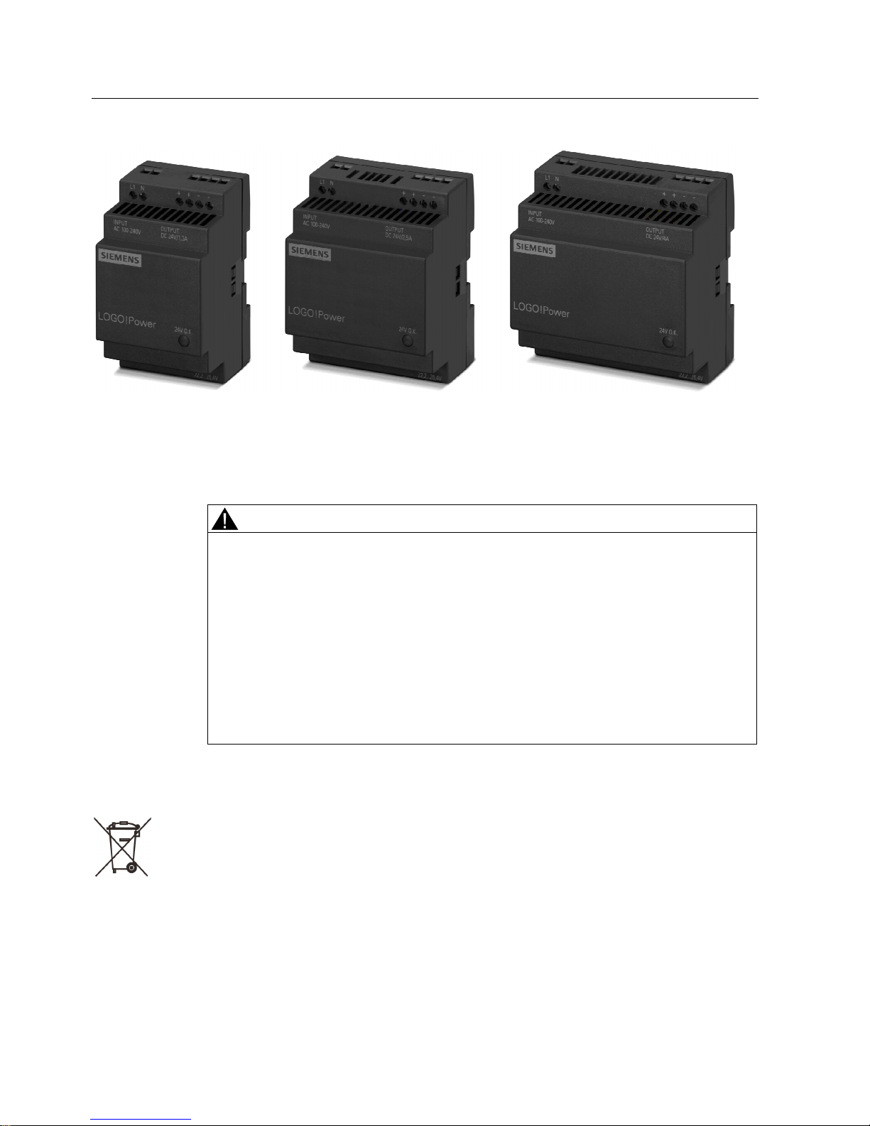
Description
LOGO!Power are powerful power supplies, which - thanks to their flat stepped profile - are
extremely flexible for use in a host of applications (for example, in installation distribution
boards). The 12 V and 24 V versions are ideal as power supplies for the LOGO! logic
modules.
The key benefits of the product include:
● Flat LOGO! mechanical design
● Wide-range input for voltages from 85 to 264 V AC and operation with DC voltage
● Adjustable output voltage
● Green LED for "Output voltage OK"
● Ambient temperature -20 °C to +70 °C (derating from +55 °C)
● Constant current under overload conditions for reliable connection of difficult loads
● When you turn on the power supply, a power reserve of 1.5 times rated current is
available for typ. 200 ms
● Export benefits thanks to global certifications
The following device options are available:
Input Output Width
100 - 240 V 1-phase AC 5 V DC / 3 A 54 mm
100 - 240 V 1-phase AC 5 V DC / 6.3 A 72 mm
100 - 240 V 1-phase AC 12 V DC / 1.9 A 54 mm
100 - 240 V 1-phase AC 12 V DC / 4.5 A 72 mm
100 - 240 V 1-phase AC 15 V DC / 1.9 A 54 mm
100 - 240 V 1-phase AC 15 V DC / 4 A 72 mm
100 - 240 V 1-phase AC 24 V DC / 1.3 A 54 mm
100 - 240 V 1-phase AC 24 V DC / 2.5 A 72 mm
100 - 240 V 1-phase AC 24 V DC / 4 A 90 mm
Page 4
Overview
LOGO!Power
4 Operating Instructions, 02.2011, C98130-A7560-A999-1-7619
Safety and warning information
WARNING
When operating electrical devices, it is inevitable that certain components will carry
dangerous voltages.
Therefore, failure to handle the units properly can result in death or serious physical injury
as well as extensive property damage.
Only appropriately qualified personnel may work on or in the vicinity of this equipment.
Perfect, safe, and reliable operation of this equipment is dependent on proper
transportation, storage, installation and mounting.
Before installation or maintenance work can begin, the system's main switch must be
switched off and measures taken to prevent it being switched on again.
If this instruction is not observed, touching live parts can result in death or serious injury.
Disposal guidelines
Packaging and packaging aids can and should always be recycled.
The product itself may not be disposed of as domestic refuse.
Page 5

Overview
LOGO!Power
Operating Instructions, 02.2011, C98130-A7560-A999-1-7619
5
Ordering data
LOGO!Power
regulated power supply
6EP1311-1SH03 5 V / 3 A
6EP1311-1SH13 5 V / 6.3 A
6EP1321-1SH03 12 V / 1.9 A
6EP1322-1SH03 12 V / 4.5 A
6EP1351-1SH03 15 V / 1.9 A
6EP1352-1SH03 15 V / 4 A
6EP1331-1SH03 24 V / 1.3 A
6EP1332-1SH43 24 V / 2.5 A
6EP1332-1SH52 24 V / 4 A
Page 6

Overview
LOGO!Power
6 Operating Instructions, 02.2011, C98130-A7560-A999-1-7619
Page 7

LOGO!Power
Operating Instructions, 02.2011, C98130-A7560-A999-1-7619
7
Table of contents
Overview.................................................................................................................................................... 3
1 Description, device design, dimension drawing ......................................................................................... 9
1.1 Device description..........................................................................................................................9
1.2 Connections and terminal designation.........................................................................................10
1.3 Potentiometer...............................................................................................................................10
1.4 Status displays and signaling.......................................................................................................11
1.5 Block diagram ..............................................................................................................................11
1.6 Dimensions and weight ................................................................................................................12
2 Mounting/Disassembly............................................................................................................................. 13
3 Mounting position, installation clearances................................................................................................ 15
3.1 Standard mounting position .........................................................................................................15
3.2 Other mounting positions .............................................................................................................15
4 Installation ............................................................................................................................................... 17
4.1 Line-side connection ....................................................................................................................17
4.2 Output-side connection ................................................................................................................18
5 Applications ............................................................................................................................................. 19
5.1 Parallel connection to increase power rating ...............................................................................19
5.2 Parallel connection for redundancy .............................................................................................20
5.3 Series connection for increased voltage......................................................................................21
5.4 Protection against short-time voltage dips ...................................................................................21
6 Technical data ......................................................................................................................................... 23
6.1 Input .............................................................................................................................................23
6.2 Output ..........................................................................................................................................25
6.3 Closed-loop control ......................................................................................................................27
6.4 Efficiency and power loss ............................................................................................................27
6.5 Protection and monitoring ............................................................................................................28
7 EMC ........................................................................................................................................................ 29
8 Ambient conditions ...........................................
....................................................................................... 31
9 Safety ...................................................................................................................................................... 33
10 Certifications............................................................................................................................................ 35
11 MTBF....................................................................................................................................................... 37
Page 8

Table of contents
LOGO!Power
8 Operating Instructions, 02.2011, C98130-A7560-A999-1-7619
12 Environment ............................................................................................................................................ 39
13 Accessories ............................................................................................................................................. 41
14 Service & Support.................................................................................................................................... 43
Page 9
LOGO!Power
Operating Instructions, 02.2011, C98130-A7560-A999-1-7619
9
Description, device design, dimension drawing
1
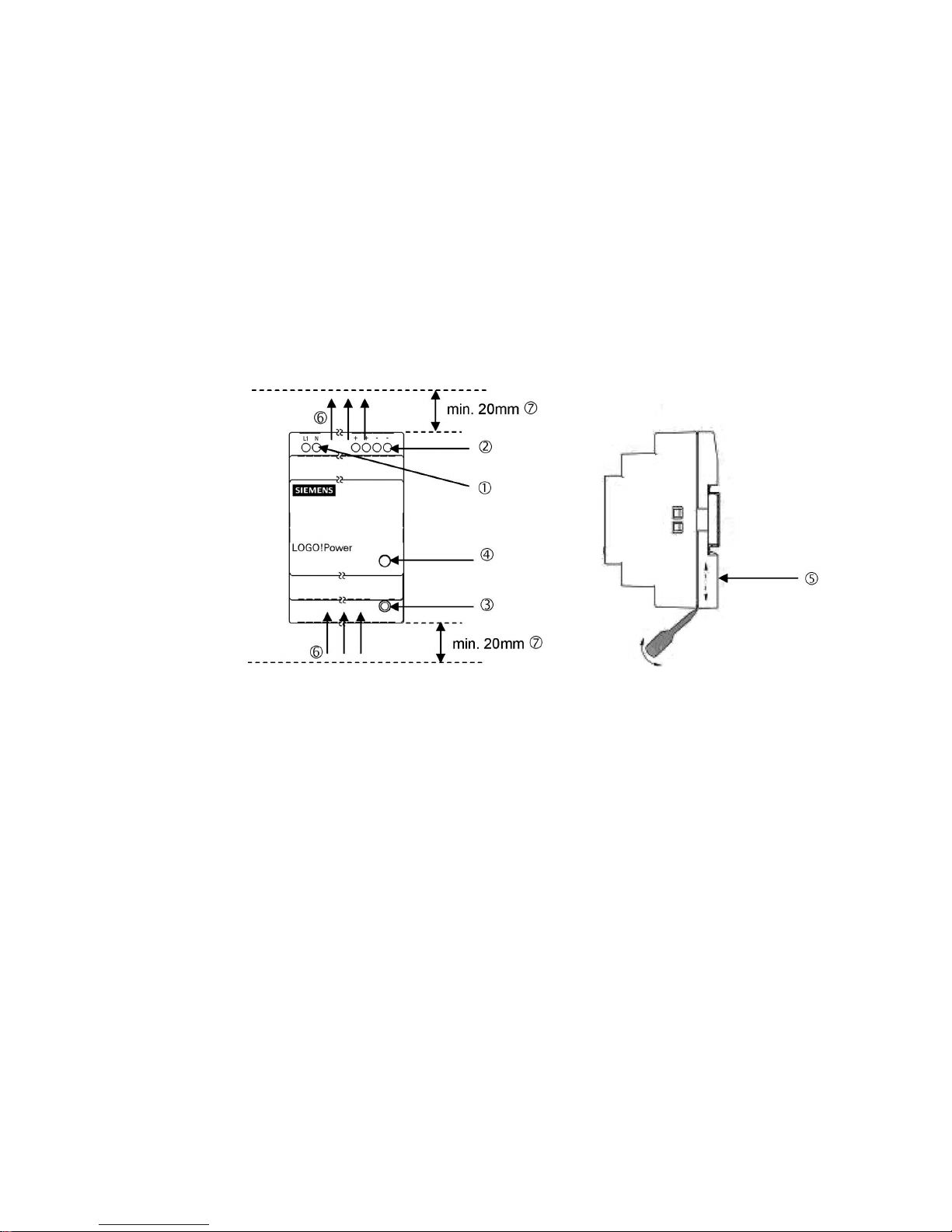
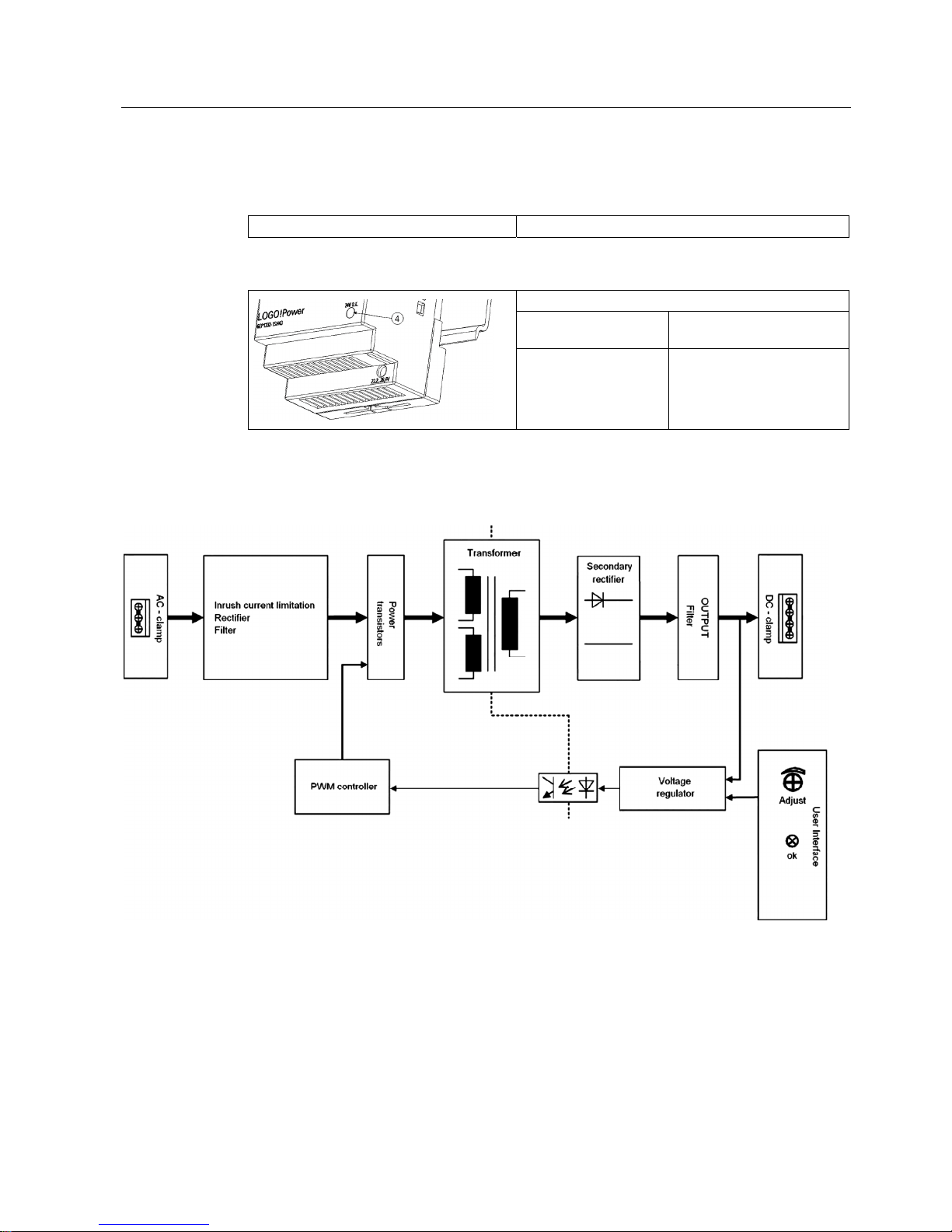
1.1 Device description
LOGO!Power are primary switched-mode power supplies for connection to a 1-phase AC
system or to DC systems. An electronically regulated DC voltage that can be set via a
potentiometer is available at the output of the device. The output of the device is isolated,
no-load proof and short-circuit proof. The LED display indicates the operating status.
① Line input
② DC output
③ Potentiometer
④ Indicator light (output voltage OK)
⑤ DIN rail slider
⑥ Natural convection
⑦ Clearance above/below
Figure 1-1 Structure
Page 10
Description, device design, dimension drawing
1.2 Connections and terminal designation
LOGO!Power
10 Operating Instructions, 02.2011, C98130-A7560-A999-1-7619
1.2 Connections and terminal designation
The line input terminals ① can be used to establish the connection to supply voltage. The
output terminals
② to be supplied are used to connect the loads (see also Section
Installation (Page 17)).
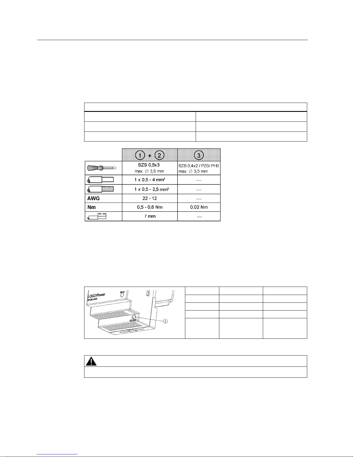
Connections and terminal designations
① Supply input L1, N
One screw terminal each for 0.5 to 2.5 mm²
② Output +
2 screw terminals for 0.5 mm to 2.5 mm²
② Output –
2 screw terminals for 0.5 mm to 2.5 mm²
Figure 1-2 Terminal data
1.3 Potentiometer
The potentiometer ③ on the front of the device is used to set the output voltage. The output
voltage is set to the rated value at the factory and can be set within certain limits; for
example, to compensate voltage drops across long supply lines to the connected load.
Type Factory setting Setting range
5 V 5 V 4.6 to 5.4 V
12 V 12 V 10.5 to 12.9 V
15 V 15 V 13.9 to 16.1 V
24 V 24 V 22.2 to 26.4 V
WARNING
Actuation of the potentiometer is allowed only be means of an insulated screwdriver.
Notes on potentiometer operation (such as a screwdriver, torque) refer to Chapter
Connections and terminal designation (Page 10), Fig. Terminal data.
Page 11
Description, device design, dimension drawing
1.4 Status displays and signaling
LOGO!Power
Operating Instructions, 02.2011, C98130-A7560-A999-1-7619
11
1.4 Status displays and signaling
Status display Green LED for output voltage OK
Signaling
LED ④ lights up green
Normal operation, output
voltage in setpoint range
LED ④ off
Supply voltage missing or
output voltage is not in
setpoint range due to
overload
1.5 Block diagram
Figure 1-3 Block diagram
Page 12
Description, device design, dimension drawing
1.6 Dimensions and weight
LOGO!Power
12 Operating Instructions, 02.2011, C98130-A7560-A999-1-7619
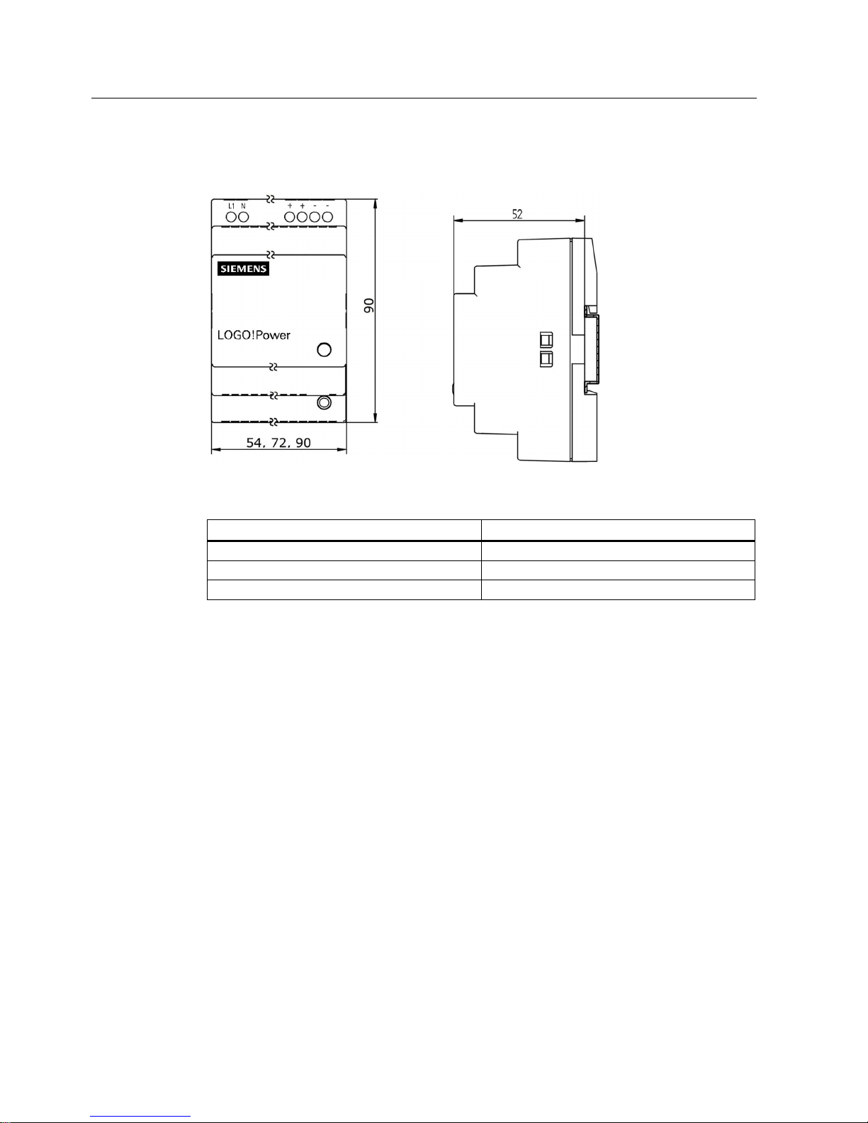
1.6 Dimensions and weight
Figure 1-4 Dimension drawing
Dimensions (W × H × D) Weight
54 × 90 × 55 mm Approx. 160 g
72 × 90 × 55 mm Approx. 250 g
90 × 90 × 55 mm Approx. 320 g
Page 13
LOGO!Power
Operating Instructions, 02.2011, C98130-A7560-A999-1-7619
13
Mounting/Disassembly
2
WARNING
The LOGO!Power power supplies are built-in units. They must be installed in a casing or
control cabinet to which only qualified personnel have access.
The devices can be snapped onto standard mounting rail EN 60715 35x7.5/15 for installation
in a control cabinet.
Installation
To mount the device, position it with the mounting rail guideway at the upper edge of the DIN
rail and press down to lock it into place. If this is too difficult, press slider
① at the same
time, as described for "Disassembly".
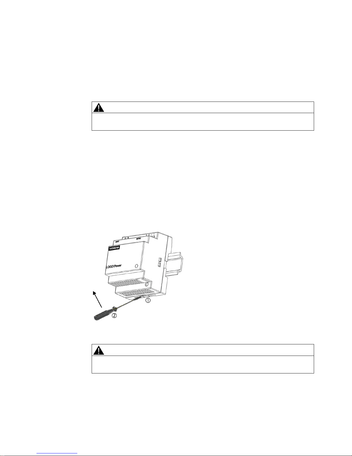
Deinstalling
To remove, pull up the slider
① using a screwdriver ② and disengage the device at the
bottom edge of the DIN rail. Then you can remove the device from the upper edge of the DIN
rail.
Figure 2-1 Deinstalling
WARNING
If the device is to be used in a hazardous area (Ex II 3G Ex nA IIC T3) it must be installed
in a distributor box with degree of protection IP54 or higher.
Page 14

Mounting/Disassembly
LOGO!Power
14 Operating Instructions, 02.2011, C98130-A7560-A999-1-7619
Page 15

LOGO!Power
Operating Instructions, 02.2011, C98130-A7560-A999-1-7619
15
Mounting position, installation clearances
3
3.1 Standard mounting position
The device is designed for installation on a standard mounting rail EN 60715 35x7.5/15. The
device must be mounted vertically to ensure proper cooling, and with the input terminals and
output terminals at the top.
A clearance of at least 20 mm should be maintained above and below the device. No space
is required at the side.
3.2 Other mounting positions
For mounting positions that deviate from the standard mounting position, derating factors
(reduction of the output power or the permissible ambient temperature) must be observed in
accordance with the following diagrams.
Figure 3-1 Mounting position (1)
Figure 3-2 Mounting position (2)
Page 16

Mounting position, installation clearances
3.2 Other mounting positions
LOGO!Power
16 Operating Instructions, 02.2011, C98130-A7560-A999-1-7619
Figure 3-3 Mounting position (3)
Figure 3-4 Mounting position (4)
NOTICE
In the case of mounting postilions that deviate from the standard mounting position,
reduced mechanical resistance of the devices against vibration and shock must be
expected. Particularly when installing on a vertically fastened standard mounting rail,
additional measures may be required, e.g. to prevent the device from slipping on the
standard mounting rail.
Page 17

LOGO!Power
Operating Instructions, 02.2011, C98130-A7560-A999-1-7619
17
Installation
4
WARNING
Before installation or maintenance work can begin, the system's main switch must be
switched off and measures taken to prevent it being switched on again. If this instruction is
not observed, touching live parts can result in death or serious injury.
4.1 Line-side connection
The LOGO!Power power supplies are power packs acc. to safety class II (without protective
conductor or equivalent without PE). LOGO!Power are designed for connection to a 1-phase
AC supply network (TN or TT system in accordance with VDE 0100 T 300 / IEC 364-3) with
rated voltage 1-phase 100-240 V AC, 50/60 Hz or to a power supply with 110-300 V DC .
Figure 4-1 Line connection
The connection of power supply network is made via the terminals L1 and N (see Fig. 4-1)
and must be established in accordance with IEC 60364 and EN 50178. A protective device
(miniature circuit breaker or circuit breaker) and a disconnection unit for the power supply
must be provided. A residual current circuit-breaker must not be used as the only protective
measure against indirect contact; this applies to the entire supply system that is protected by
the residual current operated circuit breaker.
Line-side protection (IEC 898) to be implemented upstream:
● Circuit breaker characteristic C, from 10 A or
● circuit breaker characteristic B, from 16 A
Other country-specific regulations may have to be observed when installing the device.
Page 18

Installation
4.2 Output-side connection
LOGO!Power
18 Operating Instructions, 02.2011, C98130-A7560-A999-1-7619
4.2 Output-side connection
The LOGO!Power power supplies provide an isolated (= non-grounded) SELV (Safety Extra
Low Voltage) output voltage at the output. The output of the power supplies is no-load,
overload, and short-circuit proof. If overload occurs, the electronic current limitation limits the
output current to a maximum value (refer to chapter Technical data, Output (Page 25)).
Figure 4-2 Connection of the output voltage
The output voltage is connected via the + and - terminals at the output of the power supply
(see Fig. 4-2). Make sure that the output cables are dimensioned correctly for the maximum
output current rms value and fused accordingly.
Note
When using LOGO!Power in conjunction with devices of the protection class I (with
protective conductor), a connection must be established between "-" and "PE" with at least
1.5 mm².
Page 19

LOGO!Power
Operating Instructions, 02.2011, C98130-A7560-A999-1-7619
19
Applications
5
5.1 Parallel connection to increase power rating
To enhance performance, two LOGO!Power power supplies of the same type can be
galvanically connected in parallel.
The following must be observed:
● The cables connected to each power supply at terminals "+" and "-" must have identical
lengths and the same cable cross-sections (or the same impedance) up to a common
external network junction (terminal strip) if possible.
● The parallel-switched power supplies must be switched on simultaneously with a
common switch in the mains supply line (e.g. with the main switch available in control
cabinets).
● The output voltages measured in no-load operation for the power supplies that are not yet
connected in parallel should not deviate more than a maximum of 0.2 %. This usually
corresponds to the factory setting. If the output voltage is changed, you should connect
the "-" terminals and then, in no-load operation, measure the voltage difference between
the "+" terminals that have not yet been connected. The voltage difference should not
exceed 0.2%.
Figure 5-1 Parallel connection to increase power rating
CAUTION
For connection of more than two power supplies in parallel, additional measures must be
taken to prevent high backward feeding currents in the event of a secondary device fault.
For this purpose, a suitable protective circuit (e.g. decoupling diode) must be installed
between each "+" terminal of the power supply and the common connection point.
Page 20

Applications
5.2 Parallel connection for redundancy
LOGO!Power
20 Operating Instructions, 02.2011, C98130-A7560-A999-1-7619
5.2 Parallel connection for redundancy
The parallel switching of several LOGO!Power power supplies for redundancy is required
when the demands for reliability of the supply are particularly high.
If a component in the redundant supply fails, the power supply for the loads must be fully
accommodated by the remaining component. It is therefore important when dimensioning the
system to make sure that n+1 redundant switched power supplies can handle the total power
requirement of the remaining n power supplies.
To prevent loading of the remaining power supplies in the event of a secondary-side error
when one power supply fails, the respective "+" terminals of the power supplies must be
decoupled via diodes.
NOTICE
For a high reliability of the supply, it is recommended that the redundant switched power
supplies are fused separately on the line-side and, if possible, be connected to different
power supply networks.
Figure 5-2 Parallel connection for redundancy
Page 21

Applications
5.3 Series connection for increased voltage
LOGO!Power
Operating Instructions, 02.2011, C98130-A7560-A999-1-7619
21
5.3 Series connection for increased voltage
To achieve a higher output voltage, two LOGO!Power power supplies of the same type can
be connected in series. In this case, connect the "-" terminal of the first power supply to the
"+" terminal of the second power supply. The "+" terminal of the first power supply and the "-"
terminal of the second power supply are routed to the load.
Depending on grounding point of the secondary output voltage, voltages of +2×U
A
, ±UA or -
2×U
A
can be implemented.
In the case of asymmetric load distribution, it is not possible to ensure correct functionality.
WARNING
When two power supplies are connected in series, it is not possible to ensure the
permanently permissible SELV voltage of maximum of 60 V DC acc. to EN 60950 in the
event of a fault.
Figure 5-3 Series connection
5.4 Protection against short-time voltage dips
During a drop in the primary-side supply voltage, the LOGO!Power power supplies still
maintain the output voltage over a short millisecond period (see section Technical data, Input
(Page 23)).
Page 22

Applications
5.4 Protection against short-time voltage dips
LOGO!Power
22 Operating Instructions, 02.2011, C98130-A7560-A999-1-7619
Page 23

LOGO!Power
Operating Instructions, 02.2011, C98130-A7560-A999-1-7619
23
Technical data
6
6.1 Input
Rated voltage
V
e rated 1-phase 100 - 240 V AC wide-range input
AC voltage range 85 … 264 V AC
Voltage* range DC 110 to 300 V DC
Connect/shutdown threshold Typ. 80 V/70 V
Overvoltage resistance 2,3 × Ve rated, 1.3 ms
Rated line frequency; rated line frequency range 50/60 Hz; 47 to 63 Hz
6EP1311-1SH03 0.20 A
6EP1311-1SH13 0.43 A
6EP1321-1SH03 0.29 A
6EP1322-1SH03 0.67 A
6EP1351-1SH03 0.35 A
6EP1352-1SH03 0.70 A
6EP1331-1SH03 0.36 A
6EP1332-1SH43 0.69 A
Rated current
I
e rated at Ve = 230 V
6EP1332-1SH52 0.99 A
6EP1311-1SH03 < 30 A
6EP1311-1SH13 < 55 A
6EP1321-1SH03 < 30 A
6EP1322-1SH03 < 55 A
6EP1351-1SH03 < 30 A
6EP1352-1SH03 < 55 A
6EP1331-1SH03 < 30 A
6EP1332-1SH43 < 50 A
Switch-on current limitation
(+25 °C)
6EP1332-1SH52 < 30 A
6EP1311-1SH03 0.4 A2s
6EP1311-1SH13 1.2 A2s
6EP1321-1SH03 0.4 A2s
6EP1322-1SH03 1.2 A2s
6EP1351-1SH03 0.4 A2s
6EP1352-1SH03 1.2 A2s
6EP1331-1SH03 0.4 A2s
6EP1332-1SH43 1.2 A2s
I2t value
6EP1332-1SH52 1.3 A
2
s
Built-in line-side fuse Fuse
Required protection in the mains supply
conductor
Miniature circuit breakers (IEC 898
)characteristic C 10 A
or characteristic B 16 A
Mains buffering at Ia rated >40 ms (for 187 V)
Page 24

Technical data
6.1 Input
LOGO!Power
24 Operating Instructions, 02.2011, C98130-A7560-A999-1-7619
Figure 6-1 Mains buffering
Page 25

Technical data
6.2 Output
LOGO!Power
Operating Instructions, 02.2011, C98130-A7560-A999-1-7619
25
6.2 Output
Rated voltage
V
a rated Controlled, isolated DC voltage
5 V DC, 12 V, 15 V or 24 V
Total tolerance
Static line smoothing
Static load smoothing
±3 %
Approx. ±0.5 %
Approx. ±1 %
12 V, 15 V, 24 V < 200 mVpp Residual ripple
5 V < 100 mVpp
12 V, 15 V, 24 V < 300 mVpp Spikes (bandwidth: 20 MHz)
5 V < 100 mVpp
5 V 4.6 to 5.4 V
12 V 10.5 to 12.9 V
15 V 13.9 to 16.1 V
Setting range
24 V 22.2 to 26.4 V
Response on activation/deactivation No overshoot of Va (soft start)
Startup delay/voltage rise < 1.5 s/< 500 ms (typ. 70 ms/typ. 10
ms) (see the figure below)
6EP1311-1SH03 3 A
6EP1311-1SH13 6.3 A
6EP1321-1SH03 1.9 A
6EP1322-1SH03 4.5 A
6EP1351-1SH03 1.9 A
6EP1352-1SH03 4 A
6EP1331-1SH03 1.3 A
6EP1332-1SH43 2.5 A
Rated current Ia rated
6EP1332-1SH52 4 A
Current range
• Up to +55 °C
• Derating
0 ... 100% Ia rated
0 ... 70% Ia rated (at +70 °C)
Power reserve When you turn on the power supply 1.5 x Ia rated
for typ. 200 ms
Parallel switching for enhanced performance Yes, 2 units
Output characteristic (see illustration below)
Page 26

Technical data
6.2 Output
LOGO!Power
26 Operating Instructions, 02.2011, C98130-A7560-A999-1-7619
Figure 6-2 Startup delay/voltage rise
Figure 6-3 Output characteristic (typical behavior)
The device supplies a constant output voltage until the current limit is reached. In the event
of an overload, the output current and the output voltage are reduced. The device does not
switch off.
Page 27

Technical data
6.3 Closed-loop control
LOGO!Power
Operating Instructions, 02.2011, C98130-A7560-A999-1-7619
27
6.3 Closed-loop control
Dyn. mains compensation (Ve rated ±15 %) <3% Va
Dyn. load compensation (Ia: 10/90/10 %) Typ. ±2% Va
Load-step settling time
• 10 to 90 %
• 90 to 10 %
< 20 ms (typ. 0.2 ms)
< 20 ms (typ. 0.2 ms)
6.4 Efficiency and power loss
6EP1311-1SH03 Approx. 77 %
6EP1311-1SH13 Approx. 80 %
6EP1321-1SH03 Approx. 78 %
6EP1322-1SH03 Approx. 84 %
6EP1351-1SH03 Approx. 80 %
6EP1352-1SH03 Approx. 85 %
6EP1331-1SH03 Approx. 83 %
6EP1332-1SH43 Approx. 87 %
Efficiency at
Va rated, Ia rated
(at Ve 230 V)
6EP1332-1SH52 Approx. 87 %
6EP1311-1SH03 Approx. 4.6 W
6EP1311-1SH13 Approx. 8.1 W
6EP1321-1SH03 Approx. 6.4 W
6EP1322-1SH03 Approx. 10.2 W
6EP1351-1SH03 Approx. 7.1 W
6EP1352-1SH03 Approx. 10.8 W
6EP1331-1SH03 Approx. 6.3 W
6EP1332-1SH43 Approx. 8.7 W
Efficiency at Va rated, Ia
rated
(at Ve 230 V)
6EP1332-1SH52 Approx. 13.8 W
6EP1311-1SH03 Approx. 1.5 W
6EP1311-1SH13 Approx. 1.5 W
6EP1321-1SH03 Approx. 1.8 W
6EP1322-1SH03 Approx. 1.9 W
6EP1351-1SH03 Approx. 2.1 W
6EP1352-1SH03 Approx. 2.3 W
6EP1331-1SH03 Approx. 2.0 W
6EP1332-1SH43 Approx. 1.8 W
No-load power loss
(at Ve 230 V)
6EP1332-1SH52 Approx. 2.0 W
Page 28

Technical data
6.5 Protection and monitoring
LOGO!Power
28 Operating Instructions, 02.2011, C98130-A7560-A999-1-7619
6.5 Protection and monitoring
Output overvoltage protection Yes, acc. to EN 60950
Current limitation Typ. 110 % … 130 % of Ia rated when you turn
on the power supply overload capability with 150
% of Ia rated for typ. 200 ms
Short-circuit protection Characteristic curve up to 0 V
6EP1311-1SH03 Approx. 3.9 A
6EP1311-1SH13 Approx. 8.0 A
6EP1321-1SH03 Approx. 2.3 A
6EP1322-1SH03 Approx. 4.4 A
6EP1351-1SH03 Approx. 2.3 A
6EP1352-1SH03 Approx. 4.4 A
6EP1331-1SH03 Approx. 1.6 A
6EP1332-1SH43 Approx. 3.5 A
Sustained short-circuit current
rms value
6EP1332-1SH52 Approx. 7.2 A
Overload/short-circuit indicator -
Page 29

LOGO!Power
Operating Instructions, 02.2011, C98130-A7560-A999-1-7619
29
EMC
7
EN 61000-6-2 Immunity for industrial environments
Generic standards
EN 61000-6-3 Emission for residential areas
Electrostatic discharges EN 61000-4-2 6 kV contact, 8 kV air
Electromagnetic fields EN 61000-4-3 80 to 1000 MHz 10 V/m
1000 to 2000 MHz 3 V/m
2000 to 2700 MHz 1 V/m
High-speed transient disturbance
variables (burst)
EN 61000-4-4 4 kV on mains connections
2 kV at DC output
Power surges EN 61000-4-5 2 kV symmetrically on mains connections
4 kV symmetrically on mains connections
500 V symmetrical/asymmetrical on DC
output lines
High-frequency fields EN 61000-4-6 10 V; 0.15 to 80 MHz
Voltage dips EN 61000-4-11 100 % for 20 ms
60 % for 200 ms
30 % for 500 ms
Voltage interruptions EN 61000-4-11 100 % for 5000 ms
Emitted interference EN 55022 Class B
Harmonic currents EN 61000-3-2 Class A
Page 30

EMC
LOGO!Power
30 Operating Instructions, 02.2011, C98130-A7560-A999-1-7619
Page 31

LOGO!Power
Operating Instructions, 02.2011, C98130-A7560-A999-1-7619
31
Ambient conditions
8
Humidity class Climate class 3K3 to EN 60721, no condensation
Ambient temperature -20 ... +70 °C with natural convection
Derating:
• from +55 °C 2 %/K
Tested to:
• EN 60068-2-1 coldness
• EN 60068-2-2 dry heat
• EN 60068-2-78 damp heat, constant
• EN 60068-2-14 change of temperature
Transport/storage temperature -40 ... +85 °C
Tests (packed for shipping) according to:
• EN 60068-2-1 coldness
• EN 60068-2-2 dry heat
• EN 60068-2-30 damp heat, cyclic
Mechanical stressing in operation Tested to:
• EN 60068-2-6 vibration, test Fc
– 7 mm deflection in the range 5 - 9 Hz
– 2 G acceleration in the range 9 - 150 Hz
• EN 60068-2-27 shock, test Ea
– Acceleration 150 m/s2, test duration 11 ms
Damaging gases Tested to:
• EN 60068-2-42 sulfur dioxide: 10 cm
3/m3
, 4 days
• EN 60068-2-43 sulfur dioxide: 1 cm
3/m3
, 4 days
Atmospheric pressure Tested to:
• EN 60068-2-13
Operation:
• 1080 ... 795 hPa (-1000 to +2000 m)
• >2000 m: Derating factor of 5 % / 1000 m
Storage:
• 1080 ... 660 hPa (-1000 to +3500 m)
Page 32

Ambient conditions
LOGO!Power
32 Operating Instructions, 02.2011, C98130-A7560-A999-1-7619
Page 33

LOGO!Power
Operating Instructions, 02.2011, C98130-A7560-A999-1-7619
33
Safety
9
Primary/secondary isolation Yes, SELV output voltage Ua according to EN
60950 and EN 50178
Test voltage Primary/secondary 3 kVAC or corresponding DC
value
Protection class Class II (without protective conductor)
Leakage current < 250 µA
Degree of protection (EN 60529) IP20
Page 34

Safety
LOGO!Power
34 Operating Instructions, 02.2011, C98130-A7560-A999-1-7619
Page 35

LOGO!Power
Operating Instructions, 02.2011, C98130-A7560-A999-1-7619
35
Certifications
10
Certifications
CE marking Yes (2004/108/EC and 2006/95/EC)
UL/cUL approval cULus-listed (UL 508, CSA C22.2 No.107.1), File
E197259
cURus (UL60950, CSA C22.2 No. 60950) File
E151273
NEC Class2 for types:
6EP1311-1SH03 5 V/3 A
6EP1321-1SH03 12 V/1,9 A
6EP1351-1SH03 15 V/1,9 A
6EP1331-1SH03 24 V/1,3 A
6EP1332-1SH43 24 V/2,5 A
CSA approval CLASS 5318 01 - Power Supplies - for
Hazardous Locations
CLASS 5318 81 - Power Supplies - for
Hazardous Locations - Certified to U.S. Standard
Class I, Division 2, Groups A,B,C and D, T4
Class I, Zone 2, Ex nA II T4 IP20, AEx nA II T4
IP20
FM Class I, Div. 2, Groups A, B, C, and D; T4
CB scheme IEC 60950-1
Explosion protection ATEX II 3G Ex nA IIC T3 X
EN 60079-0:2006 and EN 60079-15:2005
SEMI F47 compliance 208 V-240 V IEC 61000-4-11
Marine approval Germanischer Lloyd (GL)
6EP1352-1SH52: Cert. No.:24184-04HH
All other types: Cert. No.:47994-03HH
ABS, DNV, BV, LRS in preparation for selected
types
Page 36

Certifications
LOGO!Power
36 Operating Instructions, 02.2011, C98130-A7560-A999-1-7619
Page 37

LOGO!Power
Operating Instructions, 02.2011, C98130-A7560-A999-1-7619
37
MTBF
11
Mean Time Between Failures In accordance with SN29500: >3500000 h at
40 °C, rated load, 24-h operation
Page 38

MTBF
LOGO!Power
38 Operating Instructions, 02.2011, C98130-A7560-A999-1-7619
Page 39

LOGO!Power
Operating Instructions, 02.2011, C98130-A7560-A999-1-7619
39
Environment
12
The device is RoHS-compatible.
As a rule, only non-silicon precipitating materials are used.
Page 40

Environment
LOGO!Power
40 Operating Instructions, 02.2011, C98130-A7560-A999-1-7619
Page 41

LOGO!Power
Operating Instructions, 02.2011, C98130-A7560-A999-1-7619
41
Accessories
13
No accessories.
Page 42

Accessories
LOGO!Power
42 Operating Instructions, 02.2011, C98130-A7560-A999-1-7619
Page 43

LOGO!Power
Operating Instructions, 02.2011, C98130-A7560-A999-1-7619
43
Service & Support
14
Further information via the home page
http://www.siemens.de/sitop/manuals
or
http://support.automation.siemens.com
Phone: +49 (0) 911 895 7222
Page 44

Service & Support
LOGO!Power
44 Operating Instructions, 02.2011, C98130-A7560-A999-1-7619
 Loading...