

Page 1
Manual Edition 12/2006
Controller
SIPART DR24
6DR2410
sipart
Page 2

Page 3

SIPART DR24
6DR2410
Edition 12/2006
Manual
SIPART DR24 6DR2410
C79000-G7476-C153-03
1
Page 4
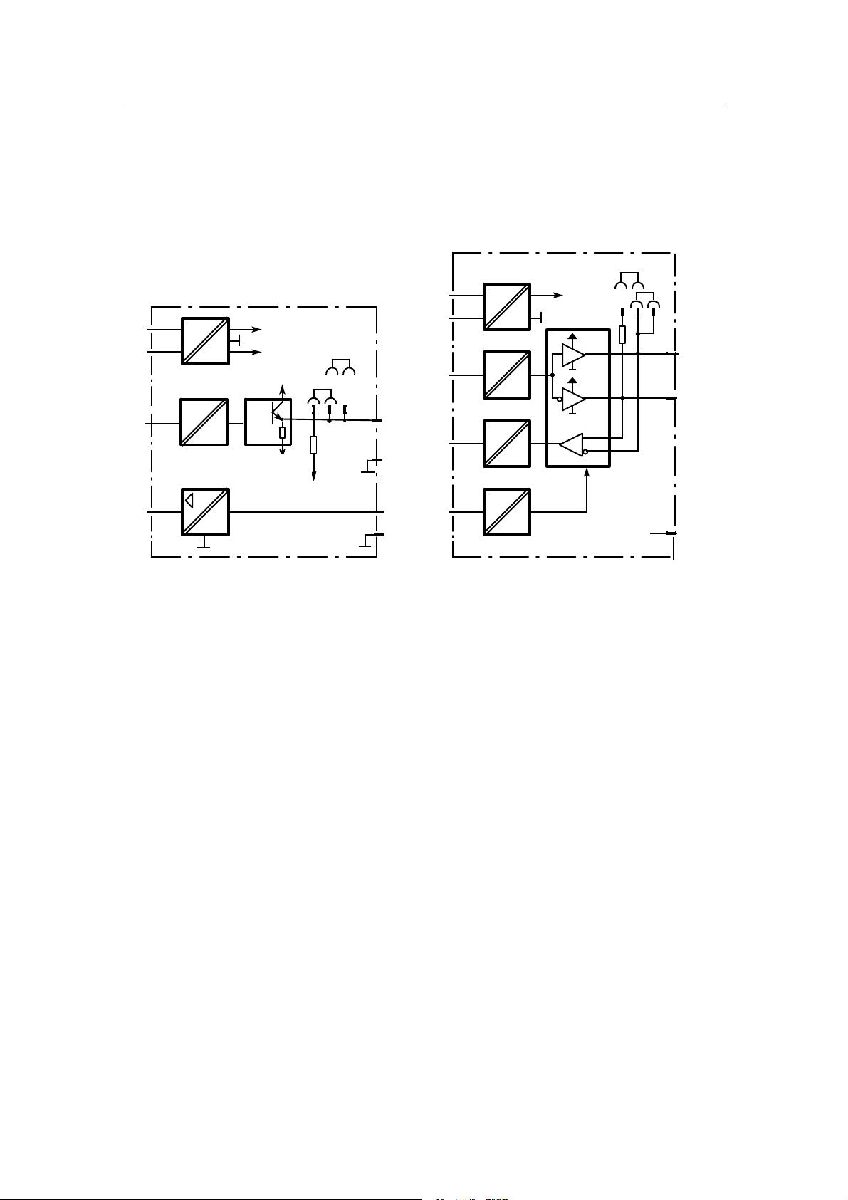
Block diagram
Manual
AE1
AE2
AE3
AE4
AE5
BE1
2
3
BE4
L+
M
+
-
+
-
+
-
Options
M
2
Front
module
1/20
1/19
1/22
1/21
1/24
1/23
2/4
2/3
2/2
2/1
3/4
3/3
3/2
3/1
1/15
1/16
1/17
1/18
1/3
1/2
1/1
PE
I,U
U
I,U
U
I,U
U
I,U,R
UNI,
P,
T,
V
U
Slot 2
I,U,R
UNI,
P,
T,
V
U
Slot 3
24 V
5V
S3
L
N
«
6DR2410-4 24 V UC
6DR2410-5 115/230 V AC switchable
32 Basic functions 109 arithmetic blocks
AbS, Add, AMEM,
AMPL, And,
ASo
bSo
CoMP, CoUn
dEbA, dEF, diF
tA1.1
div
#
Eor
tA7.F
FiLt b01.F...bh9.F
LG, LiMi, LinE with 3 inputs
Ln 1 output
AE1A
MAME, MASE
MiME, MiSE
MULt
nAnd, nor
AE2A
or
Pot
root
SUb
AE3A
tFF, tiME
33 complex funct. 33 arithmetic blocks
AFi1. AFi2
Ain1...Ain4
bin1...bin6 c01.F...c33.F
CPt1, CPt2 with 4 inputs
AE4A
dti1, dti2 1 output
FUL1, FUL2, FUL3
FUP1, FUP2
PUM1 - 4/SPR1 - SPR8
4 complex funct. 4 arithmetic blocks
CLoc d01.F...d04.F
MUP1, M UP2 with 12 inputs
AE5A
Cnt1 14 outputs
12 complex funct. 4 arithmetic blocks
Ccn1...Ccn4 h01. F...h04. F
CSE1...CSE4 with 18 inputs
CSi1...CSi4 4 outputs
bE01
bE02
bE03
bE04
I
M
+24V
+5V
U
–
REF
User
program
memory for:
onPA onAdAP line
oFPA
CLPA
hdEF offFdEF line
FCon
FPoS
APSt
CAE4
CAE5
dA1.1...dA2.4
dd1.1...dd3.4
L 1.1...L14.9
AA1.1...AA1.3
AA2.1...AA2.3
AA3.1...AA3.3
bA1.1...bA1.3
bA2.1...bA2.3
bA3.1...bA3.3
bA4.1...bA4.3
bA05
bA06
bA07
bA08
AE6A...AE8A
AA4...AA6
bE10...bE14
bA13...bA16
AE9A...AE11A
AA7...AA9
bE05...bE09
bA09...bA12
SA1.1...SA16.3
SAA1...SAA16
SbE1...SbE16
SbA1...SbA16
F
r
o
n
t
m
0000
o
d
u
l
e
5V
24 V I
3AE
1AA y
5BE
4BA24V
+2BE
2BA Rel.
3AO/3BE
Slot 6
3AE
1AA y
5BE
4BA 24V
+2BE
2BA Rel.
3AO/3BE
Slot 5
RS 232/
RS 485
PROFIBUS
Slot 4
U
U
U
hold
hold
Slot Term i n al
1/12
I
1/13
I
1/14
I
1/10
1/11
4/2
4/7
4/8
4/3
SIPART DR24 6DR2410
C79000-G7476-C153-03
1/4
1/5
1/6
1/7
1/8
1/9
6/6
6/5
6/4
6/3
6/2
6/1
Options
5/6
5/5
5/4
5/3
5/2
5/1
Options
AA1
AA2
AA3
BA1
2
3
4
5
6
7
BA8
Page 5
Manual
dA1
tA7
*) or dA2
dd1
dd2
green
red
yellow
gray
L14.0
L14.1
L14.2
L14.3
L14.4*)
L14.5
L14.6
L14.7
L14.8
L14.9
L13
dd3 L12
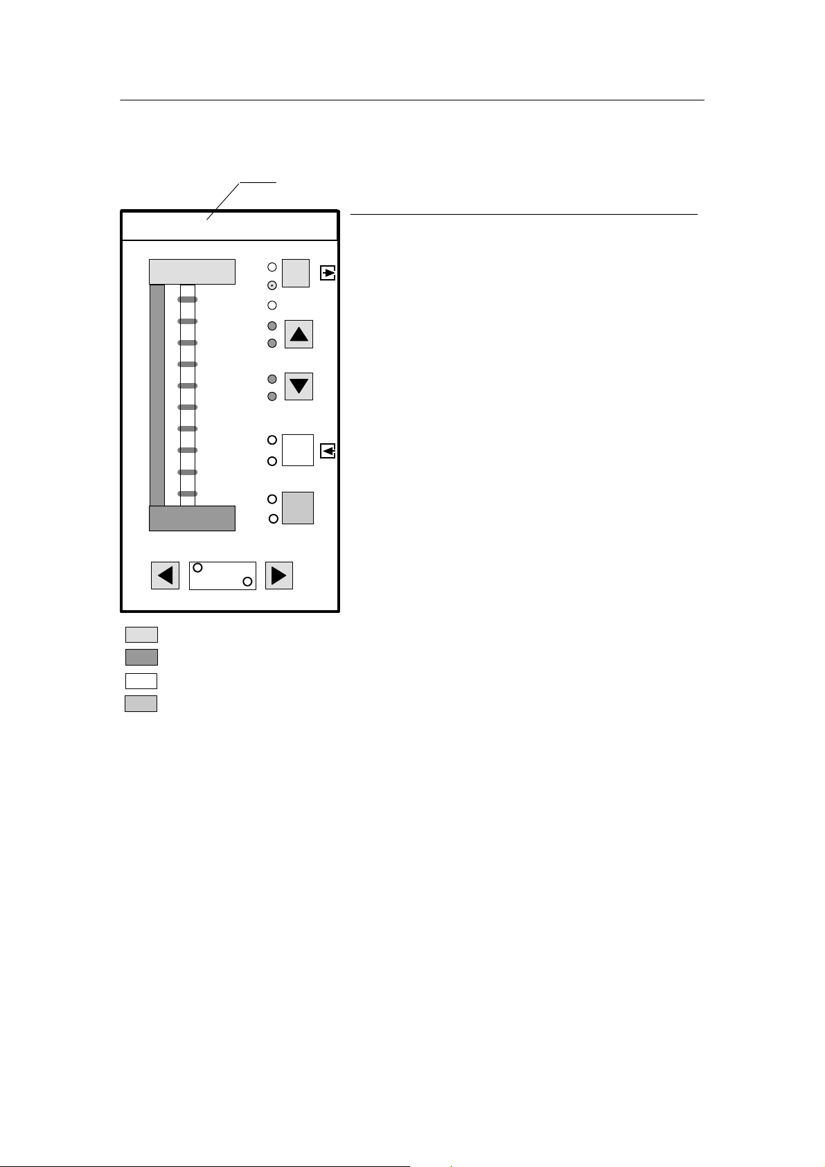
Measuring point label with cover, changeable
Process operation Parameterization/configuring
L1 LED green -tA1 Key green Exit key
L2 LED green Exit LED
L3 LED yellow -L4 LED red -L5 LED red -tA2/3 Key green Adjustment of the variables shown in
L6 LED red -L7 LED red -L8 LED yellow -tA4 Key yellow Enter key
L9 LED yellow Enter LED
L10 LED green -tA5 Key gray Shift key; start of configuration
L11 LED green -L12 LED yellow -tA6/7 Adjustment of the variables show in the
L13 LED yellow -L14.0 bis L14.9 Striped pattern in configuring
LEDs green (only as
an alternative to digital
display dA2)
dd1 Digital display green Parameter value/answer
dd2 Digital display red Function, parameter name, question
dd3 Didital display yellow Parameter name
dA1 Analog display red - dA2 Analog display green Striped pattern in configuring
(only as an alternative
to L14)
L1
L2
L3
L4
L5
L6
L7
L8
L9
L10
L11
tA1
tA2
tA3
tA4
tA5
tA6
the digital display dd1
digital displays dd2 and dd3
Figure 3-1 Connectable control and display elements in the process operation mode and fixed
assignment in parameterization/configuring
SIPART DR24 6DR2410
C79000-G7476-C153-03
3
Page 6

Manual
Classification o f safety--related notices
This manual contains notices which you shouldobserve toensure your own personalsafety, as well
as to protect the product and connected equipment. These notices are highlighted in the manual
by a warning triangle and are marked as follows according to the level of danger:
DANGER
!
!
!
indicates an immenently hazardous situation which, if not avoided, will result in death or serious inury.
WARNING
indicates a potentially hazardous situation which, if not avoided, could result in death or serious injury.
CAUTION
used with the safety alert symbol indicates a potentially hazardous situation which, if not avoided, may
result in minor or moderate injury.
CAUTION
used without the safety alert symbol indicates a potentially hazardous situation which, if not avoided, may
result in property damage.
NOTICE
indicates a potential situation which, if not avoided, may result in an undesirable result or state.
.
Copyright e Siemens AG 2006 All rights reserved
The reproduction, transmission or use of this document or
its contents is not permitted without express written authority. Offenders will be liable for damages. All rights, including rights created by patent grant or registration of a utility
model or design, are reserved.
Siemens AG
Automation and Drives
Postfach 48 48
90437 NÜRNBERG
DEUTSCHLAND
NOTE
highlights important information on the product, using the product, or part of the documentation that is of
particular importance and that will be of benefit to the user.
Trademarks
Disclaimer of Liability
We have checked the contents of this manual for agreement with the hardware and software described. Since
deviations cannot be precluded entirely, we cannot guarantee full agreement. However, the data in this manual are
reviewed regularly and any necessary corrections included
in subsequent editions. Suggestions for improvement are
welcomed.
e Siemens AG 2006
Technical data subject to change.
SIMATICR,SIPARTR,SIRECR, SITRANSR registered trademarks of Siemens AG.
Third parties using for their own purposes any other names in this document which refer to trademarks might infringe upon the
rights of the trademark owners.
4
SIPART DR24 6DR2410
C79000-G7476-C153-03
Page 7

Manual Contents
Contents
Page
1 Technical Description 7........................................................
1.1 Safety Notes and Scope of Delivery 7......................................................
1.2 Range of Application 8...................................................................
1.3 Design (Hardware) Software 8............................................................
1.4 Function Principle 11....................................................................
1.4.1 Standard Controller 11.......................................................................
1.4.2 Description of the Option Module 12...........................................................
1.4.3 Self-diagnostics of the CPU 19................................................................
1.4.4 Data Storage, User Program Memory 20.......................................................
1.5 Functional Description 21................................................................
1.5.1 Basic Structure 21..........................................................................
1.5.2 Input Functions 24..........................................................................
1.5.3 Output Functions 29.........................................................................
1.5.4 Serial Interface (SES) and PROFIBUS DP (Input/Output Functions) 34..............................
1.5.5 Data Sources with Message Function (Digital Outputs #) 36.......................................
1.5.6 Error Messages 38..........................................................................
1.5.7 Basic Functions (Arithmetic blocks b) 42........................................................
1.5.7.1 General 42.............................................................................
1.5.7.2 Mathematical Functions 44...............................................................
1.5.7.3 Logical Functions 46.....................................................................
1.5.7.4 Timing Functions 49.....................................................................
1.5.7.5 Comparison and Switching Functions 50....................................................
1.5.8 Complex Functions (Arithmetic blocks c, d, h) 52.................................................
1.5.8.1 General 52.............................................................................
1.5.8.2 Arithmetic Blocks c01.F to c33.F 53........................................................
1.5.8.3 Arithmetic Blocks d01.F to d04.F 66........................................................
1.5.8.4 Arithmetic Blocks h01.F to h04.F 75........................................................
1.5.9 Restart Conditions 91.......................................................................
1.5.10 Arithmetic 91...............................................................................
1.6 Technical Data 93.......................................................................
1.6.1 General Data 93............................................................................
1.6.2 Standard Controller 95.......................................................................
1.6.3 Technical Data of the Options Modules 99......................................................
2 Installation 107................................................................
2.1 Mechanical Installation 107..............................................................
2.2 Electrical Connection 107...............................................................
2.2.1 Block Diagram 111..........................................................................
2.2.2 Wiring of the standard Controller 112...........................................................
2.2.3 Wiring of the Option Modules 115..............................................................
2.2.4 Alternative Wiring for I- and U Input 123........................................................
2.2.5 Wiring of the Interface 128...................................................................
3 Operation 131.................................................................
3.1 Process Operation Mode 131............................................................
3.2 Selection Mode 131....................................................................
3.3 Configuring Mode (Parameterization and Configuring Mode) 135..............................
3.3.1 Parameterization Mode onPA (Online Parameters) 136...........................................
3.3.2 Parameterization Mode AdAP (Adaptation) 138..................................................
3.3.3 Configuring Mode oFPA (Offline Parameters) 145................................................
3.3.4 Configuring Mode CLPA (Clock Parameters) 148................................................
3.3.5 Configuring Mode hdEF (Define Hardware) 150..................................................
3.3.6 Configuring Mode FdEF (Define Functions) 152..................................................
3.3.7 Configuring Mode FCon (Switch Functions, Connection) 155.......................................
3.3.8 Configuring Mode FPoS (Position Functions) 159................................................
3.3.9 Configuring Mode APSt (All Preset, Factory Setting) 162..........................................
SIPART DR24 6DR2410
C79000-G7476-C153-03
5
Page 8

Contents
3.3.10 Configuring Mode CAE4/CAE5 -- Setting UNI Module(s) 163.......................................
3.3.10.1 Measuring Range for mV (SEnS=Mv.) 164...................................................
3.3.10.2 Measuring Range for U, I (SEnS=Mv.) 164..................................................
3.3.10.3 Measuring Range for Thermocouple with Internal Reference Point (SEnS=tc.in) 165................
3.3.10.4 Measuring Range for Thermocouple with External Reference Point (SEnS=tc.EH) 165..............
3.3.10.5 Measuring Range for PT100--4--wire and PT100--3--wire Connection (SEnS=Pt.3L/PT.4L) 165.......
3.3.10.6 Measuring Range for PT100--2--wire Connection (SEnS=Pt.2L) 166.............................
3.3.10.7 Measuring Range for Resistance Transmitter (SEnS=r._ for R < 600 Ω, SEnS=r. for R< 2.8 kΩ) 166..
Manual
4 Commissioning 167...........................................................
4.1 General Information 167.................................................................
4.2 Test 167..............................................................................
5 Maintenance 169..............................................................
5.1 General Information and Handling 169....................................................
5.2 Spare Parts List 173....................................................................
6 Ordering Data 175.............................................................
7 User Examples 177............................................................
7.1 Maximum Selection (Example 1) 177......................................................
7.2 Mathematical Link (Example 2) 180.......................................................
7.3 Set Value Controller K (Example 3) 184....................................................
7.4 Two-position Controller for Heating and Cooling (Example 4) 188..............................
7.5 Switching Over the Display Levels (Process Operation Mode) (Example 5) 191.................
8 Programming Aids 195........................................................
9 List of Abbreviations 261......................................................
Index 267..........................................................................
6
SIPART DR24 6DR2410
C79000-G7476-C153-03
Page 9

Manual
1 Technical Description
1.1 Safety Notes and Scope of Delivery
1.1 Safety Notes and Scope of Delivery
1 Technical Description
!
WARNING
When operating electrical equipment, certain parts of this equipment
automatically carry dangerous voltages. Failure to observe these
instructions could therefore lead to serious injury or material damage.
Only properly trained and qualified personnel are allowed to work on this
equipment. This personnel must be fully conservant with all the
warnings and commissioning measures as described in this Manual.
The perfect and safe operation of this equipment is conditional upon
proper transport, proper storage, installation and assembly as well as on
careful operation and commissioning.
D Scope of delivery
When the controller is delivered the box also contains:
1 Controller as ordered
1 three--pin plug at 115/230 V AC or special plug at 24 V UC
2 Clamps, pluggable
1 Assembly and installation instructions German/English, order number
C79000-M7474-C38
D Basic equipment
The following variants of the SIPART DR24 are available:
Order number Power supply
6DR2410-4
6DR2410-5
24 V UC
115/230 V AC, switchable
D Option module
Signal converters have separate ordering and delivery items. For handling reasons basic
equipment and signal converters which were ordered at the same time may be delivered by
separate mail.
D Documentation
This user’s guide is available in the following languages:
English C79000-G7476-C153
German C79000-G7400-C153
SIPART DR24 6DR2410
C79000-G7476-C153-03
7
Page 10

1 T echnical Description
1.2 Range of Application
Manual
D Subject to change
The manual has been compiled with great care. However, it may be necessary within the
scope of product care to make changes to the product and its operation without prior notice
which are not contained in this manual. We are not liable for any costs ensuing for this reason.
1.2 Range of Application
The SIPART DR24 is a digitally operating device in the top class range. Its program memory
contains a large number of prepared function blocks for calculating, controlling, regulating in
chemical engineering processes which the user can implement without programming knowledge
and additional tools. Mathematical functions, logical functions, comparison and switching functions, timing functions, memory functions, control functions and a program generator are stored.
All function blocks are freely connectable with each other and with different inputs and outputs
of the controller by the software.
The controller can therefore be used to solve a wide range of different problems. A large number of display elements (digital, analog displays, LEDs) and control elements allow display and
control of the processes on the front panel.
This controller contains a rugged adaptation procedure for the stored controller components
which noticeably simplifies commissioning of even critical control loops. The controller determines the optimized control parameters independently on request without the user being expected to have any prior knowledge of how the control loop may respond.
The SIPART DR24 can operate with up to 4 independent control loops. Tasks in which it is necessary to use interconnected control equipment (e.g. cascaded control, cascaded ratio controls
or override controls) can therefore be performed with one controller .
The extensive hardware equipment of the controller allows its universal application and provides
a large number of interfaces to the control loop.
The controller can be connected to master systems through a pluggable serial interface
(RS 232/RS 485 or PROFIBUS DP) or operated and monitored centrally by a Personal
Computer.
1.3 Design (Hardware) Software
The SIPART DR24 has a modular design and is therefore service friendly and easy to convert
and retrofit. Other signal converters can be installed in the generously equipped, fully functional
standard controller to expand the range of application. These modules are installed in slots at
the back of the closed device (Figure 1--2, page 10).
The standard controller consists of
-- the front module with the control and display elements
-- the main board with CPU and terminal strips
-- the plastic housing with an interface board
-- the power supply unit.
8
SIPART DR24 6DR2410
C79000-G7476-C153-03
Page 11

Manual
1.3 Design (Hardware) Software
1 Technical Description
The electrical connections between the modules are made by an interface board screwed into
the housing. The main board is pushed into rear slot 1 and locked. It holds a 10--pin and a
14--pin terminal strip to which all inputs and outputs of the standard controller are connected.
Five other slots can be equipped with option modules if the number of terminals to the process
available in the standard controller are not sufficient for the planned task.
The basic device always has three permanently installed analog inputs (AE) with electronic potential isolation which can be wired alternatively with standardized voltage signals (0/0.2 to 1 V
or 0/2 to 10 V) or current signals (0/4 to 20 mA). There are also four digital inputs (BE, 0/24 V)
and eight digital outputs (BA, 0/24 V, 50 mA) which can be used for different functions depending on the configuration.
The SIPART DR24 also has three analog outputs which can all supply a current signal from 0 to
20 mA or 4 to 20 mA and be assigned to different variables.
A short--circuit--proof L+--output (DC 24 V , 100 mA) is available for supplying transmitters.
The power supply unit is located in a fully enclosed metal casing and is screwed tightly to the
plastic housing of the controller.
Many applications can be implemented with the three permanently available analog inputs of
the standard controller alone. Two additional input modules can be inserted in slots 2 and 3 for
complex jobs or for the connection of other input signals. These input modules are available in
addition to for processing normalized current and voltage signals for the direct connection of
resistance thermometers Pt100 and all common thermocouples and resistance sensors or potentiometers. In addition a module with three analog inputs (equipment as in the standard controller) can be inserted in slots 5 and 6. This increases the number of inputs to a total of 11.
Slot 4 serves to accommodate an interface module (SES) with V.28 point-to-point output or
SIPART bus interface for serial communication with a master system. A PROFIBUS interface
module can be equipped optionally here.
The slots 5 and 6 can accommodate signal converters of different functions and can be
equipped optionally with modules for expanding digital inputs or digital outputs.
Following assemblies are possible:
2 relays
4 digital outputs/2 digital inputs
5 digital inputs
3 analog outputs/3 digital inputs
1 analog output with digital fault output (y
function) with remote supply
hold
3 analog inputs
SIPART DR24 6DR2410
C79000-G7476-C153-03
9
Page 12
1 T echnical Description
1.3 Design (Hardware) Software
Manual
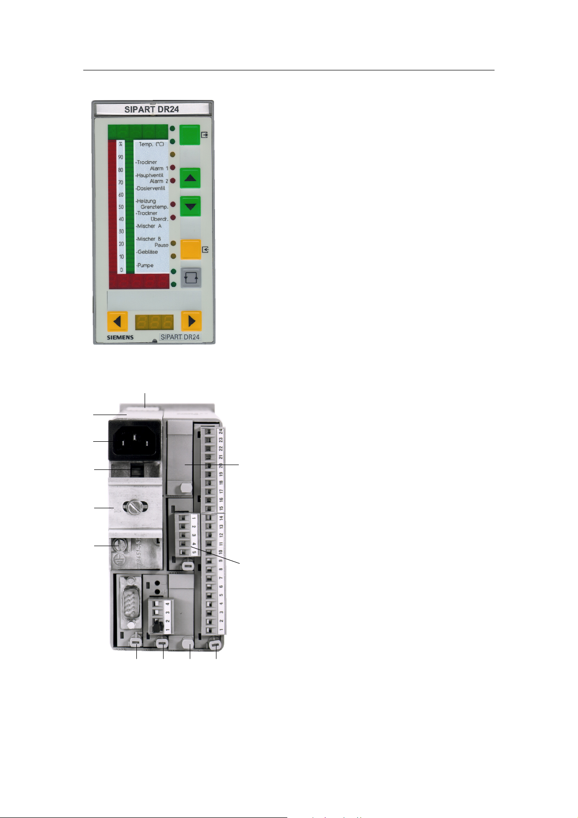
Figure 1--1 Front view of the SIPART DR24
1
12
11
10
9
8
2
3
Legend:
2. PE conductor contact spring
3. Slot 6
4. Slot 5
5. Slot 1 (main board)
6. Slot 2
7. Slot 3
8. Slot 4 (SES: RS 232/
RS 485, Profibus DP)
9. Grounding screw
10. DIN rail (DIN rail delivered with
interface relays)
11. Selection switch Mains voltage
12. Mains plug
13. Power supply unit
7 6 5 4
Figure 1--2 Rear view of the SIPART DR24
10
SIPART DR24 6DR2410
C79000-G7476-C153-03
Page 13

Manual
1 Technical Description
1.4 Function Principle
1.4.1 Standard Controller
1.4 Function Principle
1.4.1 Standard Controller
The standard controller consists of three function blocks:
-- Power supply unit
-- Front module
-- Main board
Power supply unit
Primary clocked power supply unit with high efficiency for AC 115/230 V (switchable) or for
UC 24 V. It generates the secondary internal supply voltages +24 V and +5 V from the power
supply. The metal body is mounted on PE conductors (protection class I). The power supply
and internal supply voltages are isolated from each other by safe separation by a protective
shield. The internal supply voltages are functional extra--low voltages due to overvoltage cutoff
in the event of an error. Since no further voltages are generated in the controller, these statements apply for all field signal lines (used standards, see chapter 1.6, page 93). A total of
450 mA are available for the outputs L+, AA and BA due to the design for a high power output.
Front module
The front module contains the control and display elements and the appropriate trigger components for the displays.
All display elements are designed in LED technology which provides a longer service life and
higher light density as well as a good viewing angle. The control elements are short--stroke
switches with a tangible ”pressure” and high return force. They are actuated by flexible actuators through the cover foil which are designed so that the foil is not subjected to any excess
stress.
The SIPART DR24 has a great number of functional variants. The configured buttons and display elements are activated depending on the function in the front module.
There is a foil behind the front foil which can be labeled to suit requirements. In this way the
display and control elements can be assigned to the functions.
Main board
The main board contains the field signal conditioning of the standard controller, the CPU
(Central Processing Unit) and the connections (through the interface board) to the module slots.
The field signals are fed through protective circuits for external static or dynamic overvoltages
and then adapted to the signal levels of the CPU by the appropriate circuits. This adaptation is
performed for the analog inputs, the analog outputs and the digital outputs by modern thick--film
circuits.
The microcontroller used has integrated AD- and DA converters and operates with 32k battery-backed RAM. The user--specific configuration is stored in an exchangeable user program
memory with a serial 4k EEPROM. This makes it possible to plug the user program memory in
the new controller to be installed when servicing. This then does not need to be re--configured.
SIPART DR24 6DR2410
C79000-G7476-C153-03
11
Page 14

1 T echnical Description
1.4 Function Principle
1.4.2 Description of the Option Module
Manual
The whole CPU is designed in C--MOS technology. The program of the SIPART DR24 operates
with a variable cycle time which depends on the scope of the program (see chapter 1.5.1,
page 21).
A process image is generated at the start of every routine. The analog and digital inputs and
actuation of the front buttons is included and the process variables received from the serial interface are accepted. All calculations are performed with these input signals according to the
stored functions. Then the data are output to the display elements, the analog outputs and the
digital outputs as well as storage of the calculated variables on standby for the serial interface
transmitter. The interface traffic runs in interrupt mode.
A large number of arithmetic and function blocks is stored in the set value memory of the
SIPART DR24. The user programs the controller himself by selecting, connecting and timing the
desired functions by configuration. The entire function of the controller results from the combination of the individual function blocks (basic functions, complex functions) and the corresponding input and output circuits. Programming knowledge is not necessary for the settings.
All settings are made without an additional programming device at the operating panel of the
SIPART DR24 or via the serial interface. The job--specific program written in this way is saved
in the non--volatile user program memory.
There are 32 basic function blocks b**.F and a total of 59 complex functions c**.F, d0*.F, h0*.F
which can be used with varying frequency.
No function is stored when the controllers are delivered (factory setting, all preset) The displays
are not connected. (Flashing message APSt MEM appears after switching on.)
1.4.2 Description of the Option Module
The following option modules are described in this chapter
6DR2800--8A 3 AE module
6DR2800-8J I/U module
6DR2800-8R R module
6DR2800-8V UNI module
6DR2805-8A Reference point
6DR2805-8J Measuring range plug
6DR2801-8D Module with 2 BA (relays)
6DR2801-8E Module 2 BE and 4 BA
6DR2801-8C Module with 5 BE
6DR2802-8A Analog output module with y-hold function
6DR2802-8B Module with 3AA and 3BE
6DR2803-8P Serial interface PROFIBUS-DP
6DR2803-8C Serial interface RS 232/RS 485
6DR2804-8A 4 BA relays
6DR2804-8B 2 BA relays
12
SIPART DR24 6DR2410
C79000-G7476-C153-03
Page 15

Manual
1.4.2 Description of the Option Module
1 Technical Description
1.4 Function Principle
6DR2800-8A 3 AE module
D Inputs for current and voltage
To expand the analog inputs.
Description of the module and technical data, see chapter 1.6.2, page 95 (Inputs standard controller).
6DR2800-8J I/U module
D Input variables current 0/4 to 20 mA or voltage 0/0.2 to 1 V or 0/2 to 10 V
The input amplifier of the module is designed as a differentiating amplifier with jumperable gain
for 0 to 1 V or 0 to 10 V input signal. For current input signals the 49.9 W 0.1 % impedance is
switched on by plug--in bridges on the module. The start value 0 mA and 4 mA or 0 V or 0.2 V
(2 V) is defined by configuration in the standard controller. The differentiating amplifier is designed for common mode voltages up to 10 V and has a high common mode suppression.
As a result it is possible to connect the current inputs in series as for electrical isolation when
they have common ground. At voltage inputs this circuit technique makes it possible to suppress the voltage dips on the ground rail by two--pole wiring on non floating voltage supplies.
We refer to an electronic potential isolation.
6DR2800-8R R module
D Input for resistance or current transmitter
Potentiometers with rated values of 80 Ω to 1200 Ω can be connected as resistance
transmitters. A constant current of Is = 5 mA is fed to the potentiometer wiper. The wiper
resistance is therefore not included in the measurement. Resistances are switched parallel to
the potentiometer by a slide switch on the module and a rough range selection made. Range
start and end are set with the two adjusting pots on the back of the module.
This fine adjustment can be made via the displays on the front module (with the appropriate
configuring). For adjustment with a remote measuring device, the analog output can be assigned to the appropriate input.
The external wiring must be changed for resistance transmitters which cannot withstand the
5 mA wiper current or which have a rated resistance > 1 kΩ. The constant current is then not
fed through the wiper but through the whole resistance network of the potentiometer. A voltage
divider measurement is now made through the wiper. Coarse adjustment is made by a remote
parallel resistor to the resistance transmitter.
This module can also be used as a current input with adjustable range start and end. The load
is 49.9 Ω and is referred to ground.
SIPART DR24 6DR2410
C79000-G7476-C153-03
13
Page 16

1 T echnical Description
1.4 Function Principle
1.4.2 Description of the Option Module
Manual
6DR2800-8V UNI module
D Direct connection of thermocouple or Pt100 sensors, resistance or mV transmitters
Measured value sensors such as thermocouples (TC), resistance thermometers Pt100 (RTD),
resistance transmitters (R) or voltage transmitters in the mV range can be connected directly.
The measuring variable is selected by configuring the controller in the HdeF level (AE4/AE5);
the range and the other parameters are set in the CAE4/CAE5 menu. The sensor--specific characteristics (linearization) for thermocouples and Pt100 resistance thermometers are stored in
the contoller’s program memory and are automatically taken into account. No settings need to
be made on the module itself.
The signal lines are connected via a plug terminal block with screw terminals. When using thermocouples with internal reference point, this terminal block must be replaced by the terminal
6DR2805-8A. With the measuring range plug 6DR2805--8J in place of the terminal block, the
range of the direct input (0/20...100 mV) can be extended to 0/2...10 V or 0/4...20 mA.
The UNI module operates with an AD converter with 18 bit resolution. The measuring inputs
and ground of the standard controller are electrically isolated with a permissible common mode
voltage of 50 V UC.
6DR2805-8A Reference point
D Terminal with internal reference point for thermocouples
This terminal is used in connection with the UNI module for temperature measuring with thermocouples at an internal reference point. It consists of a temperature sensor which is pre--assembled on a terminal block and plated to avoid mechanical damage.
6DR2805-8J Measuring range plug
D Measuringrangeplugforcurrent0/4to20mAorvoltage0/2to10V
The measuring range plug is used in connection with the UNI module to measure current or
voltage. The input variable is reduced to 0/20 to 100 mV by a voltage divider or shunt resistors
in the measuring range plug.
Loop resistances with 250 Ω or 50 Ω are available optionally at 2 different terminals for 0/4 to
20 mA signals.
The electrical isolation of the UNI module is retained even when the measuring range plug is
used.
6DR2801-8D 2 BA relays
D Digital output module with 2 relay contacts
To convert 2 digital outputs to relay contacts up to 35 V UC.
This module is equipped with 2 relays whose switching contacts have potential free outputs.
The RC combinations of the spark quenching elements are respectively parallel to the rest and
working contacts.
14
SIPART DR24 6DR2410
C79000-G7476-C153-03
Page 17

Manual
1.4.2 Description of the Option Module
1 Technical Description
1.4 Function Principle
In AC consumers with low power the current flowing through the capacitor of the spark quenching element when the contact is open may interfere (e.g. the hold current of some switching elements is not dropped below). In this case the capacitors (1 μF) must be removed and replaced
with low capacitance capacitors.
The 68 V suppressor diodes parallel to the capacitors act additionally to reduce the induced
voltage.
!
WARNING
The relays used on the digital output module are designed for a
maximum rating up to UC 35 V. The same applies for the air and creep
lines on the circuit board. Higher voltages may therefore only be
switched through appropriately approved series connected circuit
elements under observance of the technical data and the pertinent
safety regulations.
6DR2801-8E Module 2 BE and 4 BA
D Digital signal module with 2 digital inputs and 4 digital outputs
The module serves to extend the digital inputs and digital outputs already existing in the standard controller.
The inputs are designed for the 24 V logic and are non--floating. The functions are assigned to
the inputs and outputs by configuration of the controller.
The digital outputs are short--circuit--proof and can drive commercially available relays or the
interface relays 6DR2804--8A/8B directly.
6DR2801-8C 5 BE
D Digital input module with 5 digital inputs
The module serves to extend the digital inputs already existing in the standard controller.
The inputs are designed for the 24 V logic and are non--floating. The function is assigned to the
input by configuration of the controller.
6DR2802-8A Analog output module with y-hold function
For auxiliary control device function when servicing and for extending the analog outputs AA1 to
AA3 existing in the standard controller.
Can be used in slot 5/6, oP5/oP6 = 1 AA must be set in the hdEF structure mode
Start value of the outputs can be set with AA4/AA7 = 0/4 mA in hdEF
SIPART DR24 6DR2410
C79000-G7476-C153-03
15
Page 18

1 T echnical Description
1.4 Function Principle
1.4.2 Description of the Option Module
Manual
The y
module contains a microprocessor which maintains serial data communication with the
hold
processor on the main board through the Rxd/Txd lines. The processor feeds the U/I converter
and the CPU fault message output St
through its analog output. The module can be externally
supplied through an auxiliary voltage input which is OR--linked with the controller power supply.
The analog output of the module is freely available.
-y
function
hold
If data communication to the y
processor is interrupted, the analog output receives its last
hold
value. When data communication is restored, the slave processor reads the current variable
first. The output current is maintained if:
- the self--diagnostics of the CPU (see chapter 1.4.3, page 19) respond.
- the power supply of the SIPART fails and the y
- all modules except the power supply unit are removed (if the y
module is powered externally.
hold
module is not powered
hold
externally).
-they
module is removed (Attention: electrostatically sensitive module! Observe the
hold
safety precautions!), if it is powered externally (error message on the front module
oP. *.6 Err/oP.*.5, see chapter 1.4.3, page 19).
This makes it possible to carry out all service work up to changing the controller, e.g. in the
case of a controller (arithmetic block h0*.F), and to still maintain the controller manipulated
variable.
Handling during module replacement, see chapter 5, page 169.
Fault message output
-St
This digital output is always high when there is no error and becomes low in the event of an
error. It responds when:
- the self--diagnostics of the CPU (see chapter 1.4.3, page 19) respond.
- the controller power supply fails,
-they
module is removed,
hold
- the main board is removed.
6DR2802-8B Module with 3AA and 3BE
To extend the analog outputs (0/4 to 20 mA) and the digital inputs
Can be inserted in slot 5: AA4, AA5, AA6 BE5, BE6, BE7
and in slot 6: AA7, AA8, AA9 BE10, BE11, BE12
6DR2803-8P Interface PROFIBUS-DP
The module 6DR2803-8P is a PROFIBUS--DP interface module with RS 485 driver and electrical isolation to the controller. It operates as an intelligent converter module and adapts the private SIPART- to the open PROFIBUS-DP protocol.
This optional card can be inserted in all SIPART--DR controllers in slot 4. The following settings
must be made with the appropriate configurations for the serial interface:
16
SIPART DR24 6DR2410
C79000-G7476-C153-03
Page 19

Manual
1.4.2 Description of the Option Module
1 Technical Description
1.4 Function Principle
-- Interface on
-- Even parity
-- LRC without
-- Baud rate 9600
-- Parameters/process values writable (as desired)
-- Station number according to selection 0 to 125
Make sure that the station number is not assigned double on the bus. The PROFIBUS module
serves to connect the SIPART controllers to a master system for operating and monitoring. In
addition the parameters and configuring switches of the controller can be read and written. Up
to 32 process variables can be selected and read out cyclically by configuration of the PROFIBUS module.
The process data are read out of the controller in a polling procedure with an update time
< 300 ms. If the master writes process data to the slave, these become active after a maximum
1 controller cycle.
A technical description including the controller base file (*.GSD) is available for creating a master--slave linking software for interpreting the identifications and useful data from and to the
SIPART controller.
The discription and the GSD file can be downloaded from the INTERNET.
www.siemens.com/sipartdr
The programs SIPART S5 DP and S7 DP are offered for certain hardware configurations.
Controller base file and type file, general
The controller base file (GSD file) is necessary for connecting the controllers SIPART DR to any
remote systems.
The type file is required at present when connecting to a CPU of the SIMATIC S5/S7.
The DP master connection is parameterized with these files.
6DR2803-8C Serial interface RS 232/RS 485
D Serial interface for RS 232 or RS 485 with electrical isolation
Canbeinsertedinslot4.
For connecting the controller SIPART DR24 to a master system for operating and monitoring.
All process variables can be sent, the external setpoint, tracking variable, operating modes, parameters and configurations sent and received.
The interface traffic can take place as follows:
RS 232
SIPART Bus
RS 485
SIPART DR24 6DR2410
C79000-G7476-C153-03
As point-to-point connection
The SIPART bus driver is no longer available.
Therefore, please realize multi--couplings via RS 485 or PROFIBUS DP.
As a serial data bus with up to 32 users.
17
Page 20
1 T echnical Description
1.4 Function Principle
1.4.2 Description of the Option Module
Manual
The interface module 6DR2803--8C offers electrical isolation between Rxd/Txd and the controller. Switching can be performed between RS 232, SIPART bus and RS 485 with a plug--in
bridge.
A detailed technical description of the telegram traffic is available for creating an interface software.
RS 485+150R
RS 485
8
3
Rxd/
Txd A
Rxd/
Txd B
Txd
24 V
0V
+7.5 V
---7.5 V
+7.5V
+1
---7.5 V
RS 232
SIPART
bus
24 V
0V
Txd
2
Txd
7
Rxd
+7.5 V
+7.5 V
+7.5 V
Rxd
-1
Figure 1--3 Block diagram of serial interface for
RS 232/SIPART BUS
-7.5 V
Other connections: NC
3
Rxd
8
Rxd/
Txd
NC2, 7
Other connections: NC
Figure 1--4 Block diagram of serial interface for
RS 485
6DR2804-8A 4 BA relays
6DR2804-8B 2 BA relays
D Interface relay module with 2 or 4 relays
To convert 2 or 4 digital outputs to relay contacts up to 230 V UC.
The module can be snapped onto a mounting rail on the back of the controller. The mounting
rail is delivered with the interface relay module.
One or two relay modules with 2 relays each are installed depending on the version. Every relay
has a switching contact with spark quenching in both switching branches. In AC consumers with
a very low power, it is possible that the current flowing (e.g. hold current in contactors) through
the spark quenching capacitor (33nF) when the contact is open interferes. In this case they
should be replaced by capacitors of the same construction type, voltage strength and lower
value.
The switching contact is fed to the plug terminals with 3 poles so that rest and working circuits
can be switched. The relays can be controlled directly from the controller’s digital outputs by
external wiring.
18
SIPART DR24 6DR2410
C79000-G7476-C153-03
Page 21

Manual
1 Technical Description
1.4 Function Principle
1.4.3 Self-diagnostics of the CPU
!
WARNING
The relays used on the interface relay module are designed for a
maximum rating of AC 250 V in overvoltage class III and
contamination factor 2 according to DIN EN 61010 Part 1.
The same applies for the air and creep lines on the circuit board.
Resonance increases up to twice the rated operating voltage may
occur when phase shift motors are controlled. These voltages are
available at the open relay contact. Therefore such motors may only
be controlled under observance of the technical data and the
pertinent safety conditions via approved switching elements.
1.4.3 Self-diagnostics of the CPU
The CPU runs safety diagnostics routines which run after only a reset or cyclically. The CPU is
familiar with two different types of reset.
- Power on reset
Power on reset always takes place when the 5 V supply drops below 4.45 V, i.e. the power
supply is interrupted for longer than specified in the technical data.
All parameters and configurations are reloaded from the user program memory into the
RAM. At batt = YES (factory setting) the current process variables and status signals are
loaded from the battery- -backed RAM. At batt = no the startup conditions are fixed (see
chapter 1.5.9, page 91).
At dPon = YES in hdEF the digital displays flash as identification after a power--on reset,
acknowledgement is given by the shift key (tA5).
Flashing is suppressed with dPon = no.
The fault message source nPon is set to low at power on reset. (See chapter 1.5.5,
page 36).
- Watch dog reset
When a watch-dog-reset occurs the parameters and configurations from the user program
memory are re-loaded into the RAM. The current process variables and the status signals
are read out of the RAM for further processing.
There are no flashing signals on the front module.
CPU--tESt appears in the digital displays dd1 and dd2 for a maximum 5 s after every reset.
Every error detected by the self--diagnostics leads to a flashing error message on the digital
displays dd1 and dd2 with defined states of the analog and digital outputs. The fault message
output St
of the y
module becomes low. The reactions listed in the table are only possible of
hold
course (since this is a self- -test) if the errors occur in such a way that the appropriate outputs or
the front module can still be controlled properly or the outputs themselves are still functioning.
SIPART DR24 6DR2410
C79000-G7476-C153-03
19
Page 22

1 T echnical Description
1.4 Function Principle
1.4.4 Data Storage, User Program Memory
Manual
There are other error messages for the input range which suggest defective configurations
within this area (see chapter 1.5.6, page 38).
Error messages are also output in the adaptation (see chapter 3.3.2, page 138).
All error messages are shown by flashing digital displays.
1.4.4 Data Storage, User Program Memory
All data are written in the RAM first and then transfered to the user program memory
(EEPROM) when returning to the process operation mode (manually or via the SES).
When exchanging the main board, the user memory from the old module can be inserted into
the new module.
Writing time
The writing time after leaving the parameterization and configuring modes is up to 30 s. Then
the data are stored in a non--volatile memory.
20
SIPART DR24 6DR2410
C79000-G7476-C153-03
Page 23

Manual
1 Technical Description
1.5 Functional Description
1.5.1 Basic Structure
1.5 Functional Description
1.5.1 Basic Structure
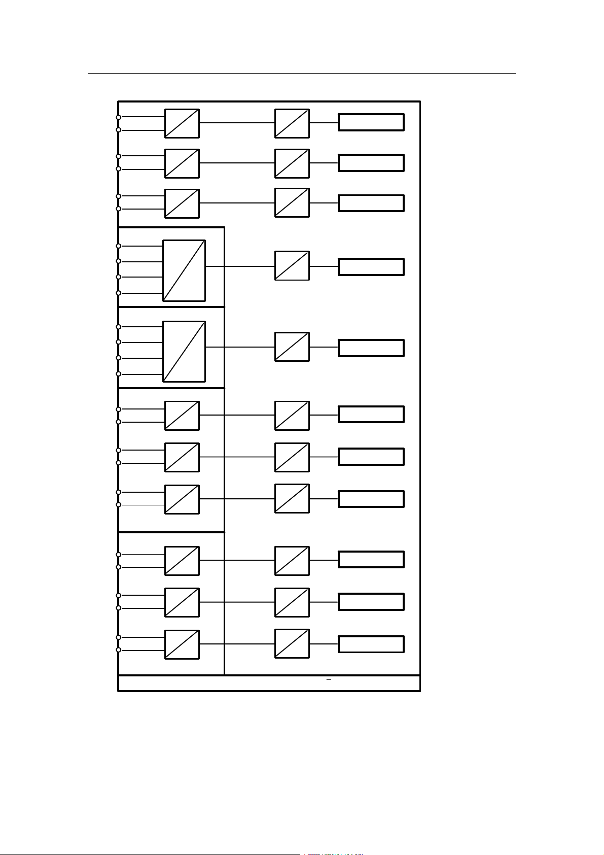
The SIPART DR24 is a freely programmable regulation, arithmetic and control unit. It consists
of the input section, the functional section and the output section. The functional structure is
illustrated in figure 1--5, page 22. The table on page 23 gives an overview of the functions which
canbeused.
The input section contains the input functions for the 11 analog inputs, the 14 digital inputs, the
7 keys and the input part of the serial interface. (Not all analog and digital inputs can be used at
thesametime!)
In configuring mode hdEF the function of the slots 5 and 6 and thus the number of BE, BA, AA
and AE functions are defined. The input functions convert the process signals (analog and digital inputs) and the manual inputs (keys) into freely connectable data sources.
The output section contains the output functions for the 9 analog outputs, the 16 digital outputs,
the 5 displays, the 13 LEDs and the output part of the serial interface.
The output functions convert the freely connectable data sinks into process signals (analog and
digital outputs) and visual outputs (displays, LEDs).
The function section is between the input and output sections. It contains 109 arithmetic blocks,
in which 32 basic functions can be freely selected and 59 complex functions which can be used
with varying frequency. In addition adjustable parameters and a number of constants and fault
messages are available for free connection. The freely connectable parameters can be used for
the standard functions which have no parameters of their own whereas the complex functions
and some of the input and output functions have private (permanently assigned) parameters.
The basic functions have a standardized input/output format, i.e. they have a maximum 3 data
sinks (inputs) and 1 data source (output).
The complex functions and the input and output functions have different input/output formats,
i.e. the number of data sinks and sources depends on the function depth.
The parameters, constants and fault messages are data sources.
By configuring on the front module, the necessary functions are selected and defined (configuring mode FdEF and hdEF), wired (configuring mode FCon) and timed in the processing (configuring mode FPoS).
Wiring is absolutely free, i.e. any data source can be connected with any data sink. The operating effort is minimized by fading out the data sources and sinks of undefined function blocks
and assigning digital data sinks to digital data sources or analog data sinks to analog data
sources. In addition the data sinks not absolutely necessary for a function can be defaulted with
constants (example: the 3rd input of an adder is defaulted with 0.000).
SIPART DR24 6DR2410
C79000-G7476-C153-03
21
Page 24

1 T echnical Description
1.5 Functional Description
1.5.1 Basic Structure
Manual
The connectable parameters and most private parameters can be set during operation in the
parameterization mode (online parameters). The other part of the private parameters is set offline in the configuring mode oFPA and CLP A.
The parameter and configuration data are stored in a non-volatile plug-in user program memory
with an EEPROM.
The cycle time in online operation depends on the scope of the user program and is a minimum
60 ms. About 2 ms are necessary on average per basic function, and about 5 ms per complex
function. The cycle time in offline operation is 100 ms.
Addition of the individual times gives the total cycle time t
which changes in 10 ms steps.
c
The current cycle time can be displayed during the lamp test (see chapter 5.1, page 169) by
additionally pressing tA1. dd3 shows the cycle time in ms.
On average you can reckon on 80 to 120 ms cycle time.
User program memory
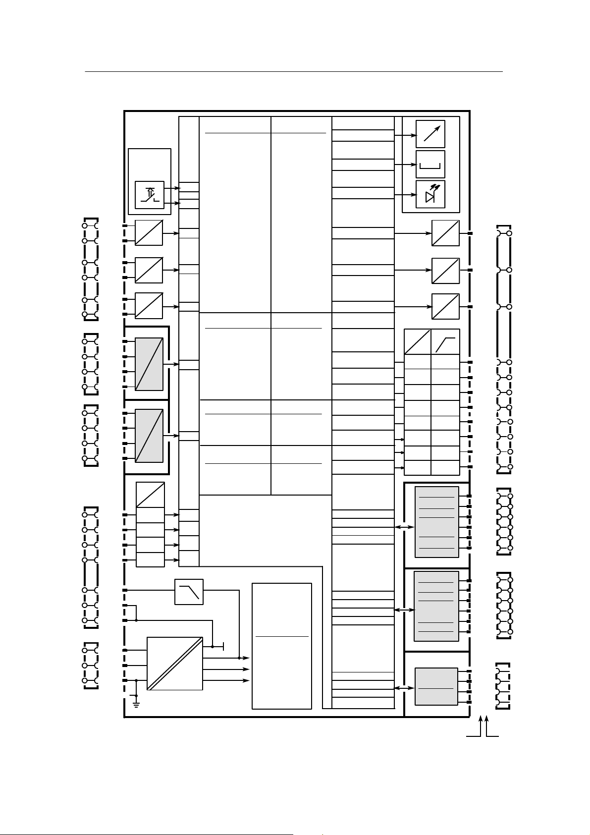
Analog inputs
AE1...11
32 basic functions
can be used in 109 arithmetic blocks
Digital inputs
bE1...14
b**.F
59 complex functions with
private parameters can be
used in blocks
Keys
ta1...7
c**.F
d0*.F
h0*.F
with varying frequency
Connectable parameters
Write SES
Analog inputs
SA(E)1...16
Constants
Fault messages
Digital inputs
Sb(E)1...16
Operating modes: Process operation
Parameterization (Online)
AdAP Adaptation
Configuring (Offline)
oFPA Offline parameters
CAE4 Parameterize UNI-module for AE4
CAE5 Parameterize UNI-module for AE5
CLPA Clock parameters
hdEF Define hardware
FdEF Define functions
FCon Wire functions
FPoS Position functions
APSt Load factory setting (all preset)
Analog outputs
AA1...9
Digital outputs
bA1...16
Displays dA1, dA2,
dd1 to dd3
LEDs
L01...13
Read SES
Analog outputs
SAA1...16
Digital outputs
Sb(A)1...16
Figure 1--5 Block diagram of the SIPART DR24
22
SIPART DR24 6DR2410
C79000-G7476-C153-03
Page 25

Manual
Functional overview SIPART DR24
1 Technical Description
1.5 Functional Description
1.5.1 Basic Structure
b = Basic function, blocks b
d = complex function, blocks d
Mathematical functions Func tion
D
AbS
Add
AMPL
CPt
div
FUL
FUP
LG
LinE
LN
MUlt
Pot
root
SUb
Comparison and switching functions Funct ion
D
AMPL
ASo
bSo
Cnt
CoMP
dEbA
LiMi
MASE
MiSE
MUP
Absolute value
Adder
Differential amplifier
P/T correction computer
Divider
Function transmitter (linear)
Function transmitter (parabola)
Decadic logarithmer
Linear equation
Natural logarithmer
Multiplier
Exponential function
Rooter
Subtractor
Differential amplifier
Analog switch over
Digital switch over
Demultiplexer
Comparator with hysteresis
Response threshold (dead band)
Limiter
Maximum selection
Minimum selection
Measuring point switch over
(analog)
c = complex function, blocks c
h = complex function, blocks h
Logical functions Fun ction
block
b
b
b
c
b
c
c
b
b
b
b
b
b
b
block
b
b
b
d
b
b
b
b
b
d
D
And
CoUn
dFF
Eor
nAnd
nor
or
SPR
tFF
tiME
Timer functions Func tion
D
AFi
Ain
bin
diF
dti
FiLt
PUM
tiME
AND
Counter
D--flip--flop
EXOR
NAND
NOR
OR
Split range
T--flip--flop
Timer (monoflop)
Adaptive filter
Integrator with analog input
Integrator with digital input
Differentiator
Dead time element
Filter (low pass)
Pulse width modulator
Timer (monoflop)
block
b
b
b
b
b
b
b
c
b
b
block
c
c
c
b
c
b
c
b
Memory functions Func tion
D
Ain
AMEM
bin
dFF
MAME
MiME
tFF
Program transmitter Func tion
D
CLoc Clock d
SIPART DR24 6DR2410
C79000-G7476-C153-03
Integrator with analog input
Analog memory
Integrator with digital input
D--flip--flop
Maximum memory (drag pointer)
Minimum memory (drag pointer)
T--flip--flop
block
c
b
c
b
b
b
b
block
Control functions Function
D
Ccn
CSE
CSi
K controller
S controller external feed
back
S controller internal feedback
block
h
h
h
23
Page 26

1 T echnical Description
1.5 Functional Description
1.5.2 Input Functions
Manual
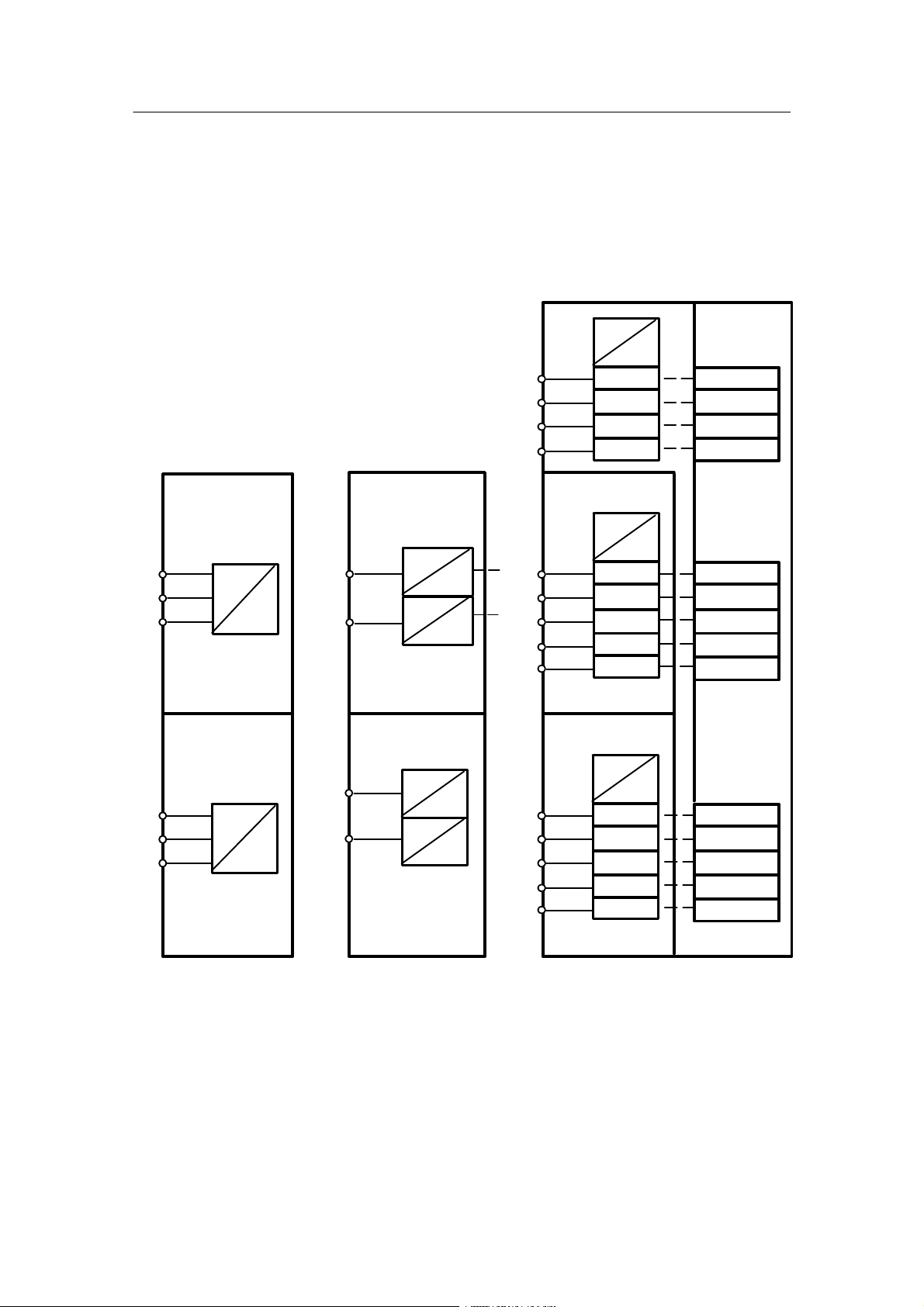
1.5.2 Input Functions
The following input functions are dealt with in detail in this chapter:
Analog inputs AE1 to AE11
Digital inputs BE1 to BE14
Data sinks bLS, bLPS, bLb
Keys tA1totA7
Analog inputs AE1 to AE11
The analog inputs AE1 to AE3 are located on the basic board and can be jumpered there.
Ranges: 1 V, 10 V, 20 mA. (The zero point can be selected via configuring mode hdEF (AE1 to
AE11).) The inputs AE4, AE5 are realized with a module card in slots 2 and 3. The inputs AE6
to AE8 are realized with a module in slot 6. The inputs AE9 to AE11 are realized with a module
in slot 5. Ranges same as AE1 to AE3.
The A/D converter inputs have a signal range from --5 % to +105 % or as an absolute value
--0.05 bis +1.05. If the evaluation of the inputs is to be changed you can switch the basic function “Multiply” (MULt) for weakening or strengthening the basic function and the basic function
“Linear equation” (LinE) to hide a range by configuring (see chapter 1.5.6, page 38).
The analog inputs AE* (*= 1 to 11) have a mains frequency suppression (configuring level
hdEF)
AEFr 50or60Hz
and the transmitter monitor AE1
to AE11 as a data source with a threshold at --3 % and
103%. The thresholds have a hysteresis of 1 %. The data source can be switched in FCon. The
fault message nAE
is set to low when the values exceed or drop below the limit. This signal
is also freely switchable in FCon.
24
SIPART DR24 6DR2410
C79000-G7476-C153-03
Page 27
Manual
1 Technical Description
1.5 Functional Description
1.5.2 Input Functions
AE1+
AE1--
AE2+
AE2--
AE3+
AE3--
AE4
AE5
AE6+
AE6--
AE7+
AE7--
AE8+
AE8--
1/20
1/19
1/22
1/21
1/24
1/23
2/1
2/2
2/3
2/4
3/1
3/2
3/3
3/4
6/2
6/1
6/4
6/3
6/6
6/5
I,U
I,U
I,U
Slot 2
I
U
R
P
T
Slot 3
I
U
R
P
T
Slot 6
I,U
3AE
I,U
6DR2800-8A
I,U
oP6 = 3AE (hdEF)
∩
U
U
U
U
U
U
U
U
#
∩
#
∩
#
∩
#
∩
#
∩
#
∩
#
∩
#
AE1A ∩
AE2A ∩
AE3A ∩
AE4A ∩
AE5A ∩
AE6A ∩
AE7A ∩
AE8A ∩
Slot 5
AE9+
AE9--
AE10+
AE10- -
AE11+
AE11--
6/2
6/1
6/4
6/3
6/6
6/5
AE1...AE11 = 0 or 4 mA / AE4...AE5 = Uni_. or Uni
I,U
U
3AE
I,U
U
6DR2800-8A
I,U
U
oP5 = 3AE (hdEF)
Figure 1--6 Input function analog inputs
SIPART DR24 6DR2410
C79000-G7476-C153-03
∩
#
∩
#
∩
#
AE9A ∩
AE10A ∩
AE11A ∩
(hdEF)
25
Page 28
1 T echnical Description
1.5 Functional Description
1.5.2 Input Functions
Manual
Digital inputs BE1 to BE14
The inputs BE1 to BE4 are located on the basic board. BE5 to 9 and 10 to 14 are connected to
the module 6DR2801--8C at the slots 5 or 6. The digital output modules 6DR2801--8E also contain another two digital inputs in addition to the outputs so that in this case the two digital inputs
BE5/BE6 or BE10/BE11 can be used.
The modules are assigned to the slots in the configuring mode hdEF.
24 V
Slot 5
3AA + 3BE
6DR2802--8B
BE5 BE5
5/1
5/2
5/3
6/1
6/2
6/3
24 V
BE6
BE7
oP5 = 3AA
(hdEF)
Slot 6
3AA + 3BE
6DR2802--8B
BE10
24 V
BE11
BE12
oP6 = 3AA
(hdEF)
5V
5V
5/1
5/6
6/1
6/6
Slot 5
4BA + 2BE
6DR2801-8E
BE6
oP5 = 4BA
(hdEF)
Slot 6
4BA + 2BE
6DR2801-8E
BE10
BE11
oP6 = 4bA
(hdEF)
24 V
24 V
24 V
24 V
5V
5V
5V
5V
1/15
1/16
1/17
1/18
5/1
5/2
5/3
5/4
5/5
6/1
6/2
6/3
6/4
6/5
BE1
BE2
BE3
BE4
Slot 5
6DR2801--8C
5BE
24 V
BE5
BE6
BE7
BE8
BE9
oP5 = 5BE
(hdEF)
Slot 6
6DR2801--8C
5BE
24 V
BE10
BE11
BE12
BE13
BE14
oP6 = 5bE
(hdEF)
5V
bE01 #
bE02 #
bE03 #
bE04 #
5V
bE05 #
bE06 #
bE07 #
bE08 #
bE09 #
5V
bE10 #
bE11 #
bE12 #
bE13 #
bE14 #
Figure 1--7 Input function digital inputs
26
SIPART DR24 6DR2410
C79000-G7476-C153-03
Page 29

Manual
1 Technical Description
1.5 Functional Description
1.5.2 Input Functions
Data sinks bLS, bLPS, bLb
These sinks serve to block operation (bLb), the parameter and configuration adjustment (bLPS)
or just the configuration adjustment (bLS). At bLPS = high an error message no(dd1) PS(dd3) is
displayed when attempting to enter the parameterization mode.
At bLS = high no error message appears but the StrU level in the parameterization preselection
is hidden. The sinks bLS, bLPS and bLB can only be switched by the binary inputs BE1 to
BE14 (bE** = source) and the SES sources SbE1 to SbE8. When the CB time monitor responds or at Cbt = oFF, the SES sources connected with bLS, bLPS or bLb are set to low. See
also chapter 3.3.7, table 3--8, page 157.
The factory setting is low.
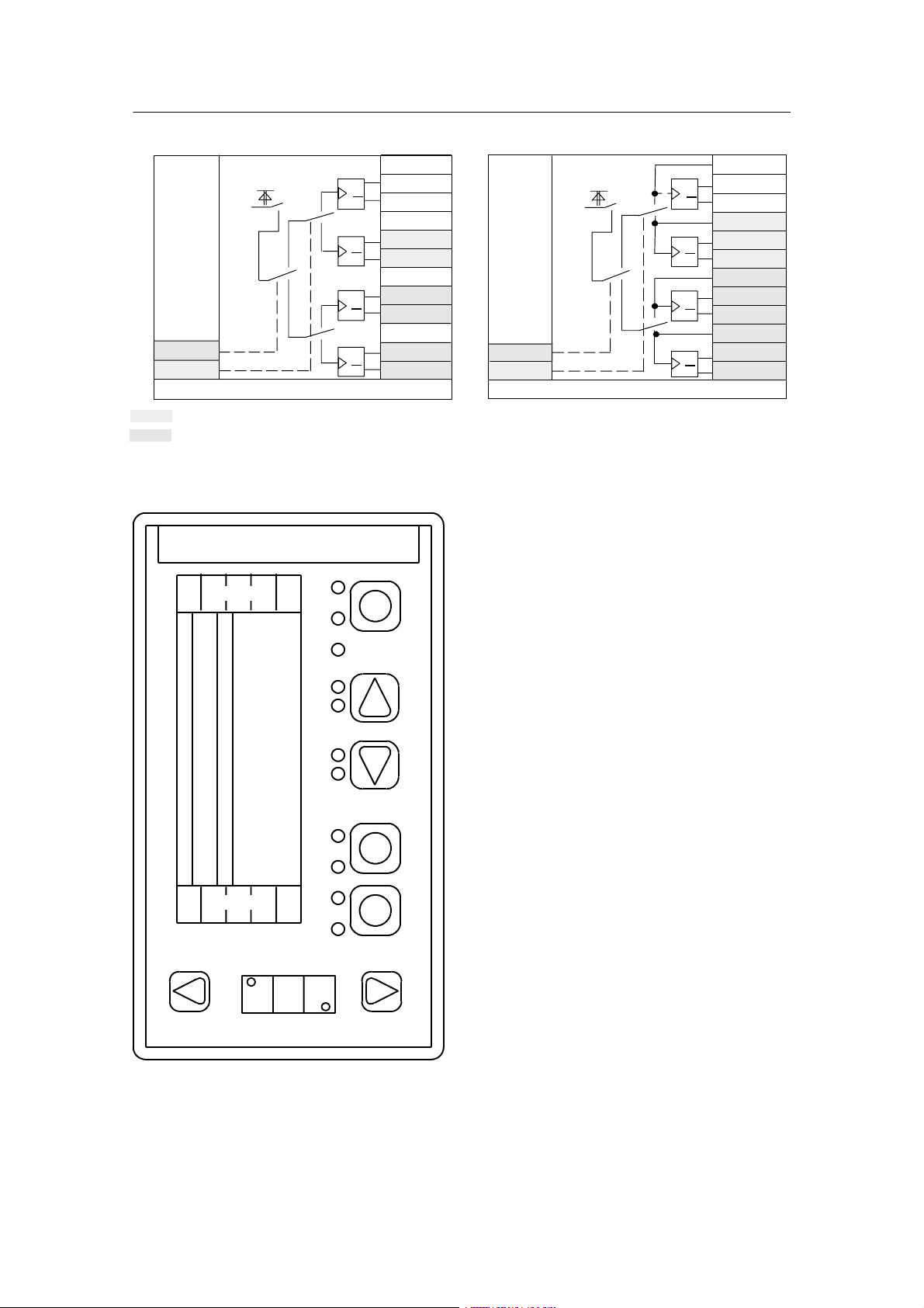
Keys tA1 to tA7
The keys (see figure 1--9, page 28) are available as key function tA*.1, tA*.2 or as switching
functions tA*.3, tA*.4 or tA*.5, tA*.6 (see figure 1--8, page 28). The keys are provided primarily
for incremental adjustment of the complex functions „Integrator with digital input” (bin) or controller inputsΔy. They can be switched by the control inputs tA*U/tA*M for quadruple applications whereby the status of the switched off outputs Q and Q
remains unchanged.
The key tA5 has no key output to other operating levels because of the universal function; i.e.
tA5.1 and possibly tA5.2 are not available. The outputs Q and Q
are switched at key 5 with the
low edge (release the key). “PS” flashes in dd3 after pressing tA5 continuously for about 5 s. All
keys lose their function in the process operating level when the display flashes in dd3.
You can now switch to the other levels (parametering, configuring). See chapter 3.3.1 (page
136), 3.3.2 (page 138) and 3.3, page 135.
When the function tA*.U is assigned „no” in the configuring mode hdEF, the shaded data
sources and sinks do not appear in the configuring mode FCon. Since the sink tA*.U is pre--assigned with low, the drawn switch position is active.
Restart conditions
Power on Q
bAtt = no
bAtt = YES
last status
0
Q
1
last status
SIPART DR24 6DR2410
C79000-G7476-C153-03
27
Page 30
1 T echnical Description
1.5 Functional Description
1.5.2 Input Functions
Hi
gr
Lo
#tA5.M
Lo
#tA5.U
#tA5.U = no/YES/Four
arehiddeninFCon,if tA*.U = no
arehiddeninFCon,if tA*.U = no/YES
Figure 1--8 Input function keys
Q
Q
Q
Q
Q
Q
Q
Q
tA5.3#
tA5.5#
tA5.4#
tA5.6#
tA5.C#
tA5.E#
tA5.d#
tA5.F#
(hdEF)
Hi
gn
Lo
#tA1.M
Lo
#tA1.U
#tA1.U = no/YES/Four
tA2, 3, 4, 6, 7 functionally identical with tA1
Q
Q
Q
Q
Q
Q
Q
Q
Manual
tA1.1#
tA1.3#
tA1.5#
tA1.2#
tA1.4#
tA1.6#
tA1.A#
tA1.C#
tA1.E#
tA1.b#
tA1.d#
tA1.F#
(hdEF)
dA1
tA7
dd1
dd2
dA2/
L14
L13
dd3
L1
L2
L3
L4
L5
L6
L7
L8
L9
L10
L11
L12
tA1
tA2
tA3
tA4
tA5
tA6
Figure 1--9 Description of the displays, keys and LEDs on the front module of the SIPART DR24
28
SIPART DR24 6DR2410
C79000-G7476-C153-03
Page 31

Manual
1.5.3 Output Functions
The following output functions are described in this chapter:
Analog outputs AA1 to AA
Digital outputs BA1 to BA16
Digital displays dd1 to dd3 (7-segment displays)
Analog displays dA1, dA2 (bar graphs)
LEDs L1 to L13, L14
Analog outputs AA1 to AA9
1 Technical Description
1.5 Functional Description
1.5.3 Output Functions
0.000
0.000
0.000
0.000
0.000
0.000
0.000
0.000
Hi
0.000
0.000
0.000
nAA1.1
nAA1.2
nAA2.1
nAA2.1
nAA3.1
nAA3.2
nAA4.1
nAA4.1
#AAU
nAA05
nAA06
nAA07
AA1
AA2
AA3
1/12
1/13
1/14
I
I
I
AA1.3 n
AA2.3 n
#
#
#
U
∩
U
∩
U
∩
AA3.3 n
Slot 6
6DR2802-8B (oP6 = 3AA)
U
#
#
AA4.3 n
1
#
#
#
Slot 5
6DR2802-8B (oP5 = 3AA)
#
U
∩
∩
U
∩
U
U
∩
∩
U
∩
AA4
I
I
AA5
I
AA6
I
I
AA7
I
Slot 6
Slot 6
6DR2802-8A (oP6 = 1AA)
6DR2802-8A (oP6 = 1AA)
#
6/4
6/5
6/6
5/4
#
∩
∩
Slot 5
Slot 5
6DR2802-8A (oP5 = 1AA)
6DR2802-8A (oP5 = 1AA)
#
#
∩
∩
U
U
U
U
AA4
AA4
6/5
AA7
AA7
6/5
5/5
5/5
I
I
I
I
0.000
0.000
nAA08
nAA09
AAU = YES or no, AA1 to AA9 = 0 or 4 mA
are hidden in FCon, if AAU = no in hdEF
#
#
Figure 1--10 Output function analog outputs AA1 to AA9
SIPART DR24 6DR2410
C79000-G7476-C153-03
I
I
(hdEF)
AA8
AA9
5/5
5/6
U
∩
U
∩
29
Page 32

1 T echnical Description
1.5 Functional Description
1.5.3 Output Functions
Manual
- The analog outputs AA1 to AA3 are available in the standard controller.
- All data sinks AA** are defaulted with 0.000 so that the analog outputs have the value 0
(0 mA/4 mA) without further wiring.
- The analog outputs AA1 to AA3 can be wired on two channels (AA*.1, AA*.2). The data
source AA*.3 allows the effective output value to be processed.
- The data sinks can be switched commonly for the four D/A converters by the control
signal AAU.
- By connecting the data source AA*.3 with the corresponding data sink AA*.2, the last active
value through AA*.1 can be kept constant after switching over.
- If = no is assigned to the AAU function in the configure mode hdEF , the shaded data
sources and sinks do not appear in the configuring mode FCon. Since AAU is defaulted with
high, the drawn switch position is then active.
- The data sinks AA*.1 and with them the analog outputs are held at the last value during con-
figuring. If this is not desired you can switch to the data sinks AA*.2 by wiring AAU with the
fault message nStr (no configuring) which can be wired for example with safety values.
These values are then retained during the entire configuring process.
Digital outputs BA1 to BA16
The 16 digital outputs are distributed on the basic board and 2 slots to every 4 digital outputs
(see figure 1--11, page 31). Either the signal converters for 2 relay outputs (6DR2801-8D) or for
4 voltage outputs 24 V (6DR2801-8E) can be plugged at every slot. For the relay outputs the
relay contacts are output with 3 poles (switching function!). The voltage outputs are fed with 24
V by the main board of the SIPART DR24.
The 2 slots can also be equipped with modules of another function, see chapter 1.5.2, page 24.
The corresponding digital outputs are then omitted.
All data sinks bA* are defaulted with low so that the digital outputs are low without further
switching. The digital outputs BA1 to BA4 can be switched on two channels. The data sources
bA1.3 to bA4.3 allow the effective status to be stored. In this way the data sinks for the 4 digital
outputs can be switched over commonly with the control signal bAU. The last status can be retained after switching over by connecting the data sources bA1.3 to bA4.3 with the corresponding data sinks bA1.2 to bA4.2.
The shaded data sources and sinks do not appear in the configuring mode FCon if no is assigned to the bAU function in the configuring mode hdEF. Since bAU is defaulted with high, the
drawn switch position is active.
The data sinks bA1 to bA16 are held at their last logical level before the switch over edge to the
1)
configuring during configuring. The digital outputs react accordingly
If this is not desired, you
can switch for bA*.1 to the data sinks bA*.2 which can be switched with safety levels for example by switching bAU with the fault message nStR (no configuring). These levels are then retained during the entire configuring process.
Note: This safety switching only applies for bA1 to bA4. For bA05 to bA16, it cannot be simu-
lated with the fault message nstr by using digital switches because no more blocks are
processed after the switch over edge to the configuring!
1)
If the digital output sources are buttons (tA1.1, tA1.2, tA2.1, tA2.2 etc.), the digital outputs are set to ”low” on leaving the process level because otherwise the buttons would be ”frozen”.
30
SIPART DR24 6DR2410
C79000-G7476-C153-03
Page 33

h1.2A
or low
h1.3A
or low
h2.2A
or low
h2.3A
or low
Manual
Lo
Lo
Lo
Lo
Lo
Lo
Lo
Lo
Hi
#bA1.1
#bA1.2
#bA2.1
#bA2.2
#bA3.1
#bA3.2
#bA4.1
#bA4.2
#bAU
#bA05
#bA06
#bA07
#bA08
1 Technical Description
1.5 Functional Description
1.5.3 Output Functions
I
I
I
I
BA1
BA2
BA3
BA4
1/4 +Δy
1/5 -Δy
1/6 +Δy
1/7 -Δy
if CSE* or CSi*
is defined in h04.F
(see also PUM1 ... 4)
if CSE* or CSi*
is defined in h03.F
bA1.3 #
bA2.3 #
bA3.3 #
5V
24 V
5V
24 V
5V
24 V
5V
24 V
bA4.3 #
-1
5V
24 V
I
BA5
BA6
BA7
BA8
1/8 +Δy
1/9 -Δy
1/10 +Δy
1/11 -Δy
if CSE* or CSi*
is defined in h01.F
if CSE* or CSi*
is defined in h02.F
Slot 5 4BA + 2BE
#bE05
#bE06
6DR2801-8E
5V
24 V
Lo
#bA09
Lo
#bA10
Lo
#bA11
Lo
#bA12
oP5 = 4bA (hdEF)
Slot 6 4BA + 2BE
#bE10
#bE11
6DR2801-8E
5V
24 V
Lo
#bA13
Lo
#bA14
Lo
#bA15
Lo
#bA16
oP6 = 4bA (hdEF)
bAU = YES or no (hdEF)
are hidden in FCon, if bAU = no in hdEF
5V
5V
24 V
I
24 V
BE5
BE6
BA9
BA10
BA11
BA12
BE10
BE11
BA13
BA14
BA15
BA16
5/1
5/6
5/2
5/3
5/4
5/5
6/1
6/2
6/2
6/3
6/4
6/5
Slot 5 2BA relays
6DR2801-8D
5V
24 V
oP5 = 2rEL (hdEF)
Slot 6 2BA relays
6DR2801-8D
5V
24 V
oP6 = 2rEL (hdEF)
I
II
5/1
BA9
5/2
5/3
5/4
5/5
BA10
5/6
6/1
BA13
6/2
6/3
6/4
6/5
BA14
6/6
Figure 1--11 Output function digital outputs
SIPART DR24 6DR2410
C79000-G7476-C153-03
31
Page 34

1 T echnical Description
1.5 Functional Description
1.5.3 Output Functions
Manual
Digital displays dd1 to dd3 (7-segment displays)
The displays serve to display the analog variables (arrangement of displays see figure 1--15,
page 34). The displays can be switched between the data sinks dd*.1 to dd*.4 by the control
inputs dd*.U/dd*.M for quadruple applications.
If the displays are not wired in the configuring mode FCon, the drawn switch positions become
active by defaulting dd*.U/dd*.M with low and the displays go dark by defaulting dd*.1 with
ncon.
∩dd1.1
ncon
∩dd1.2
ncon
∩dd1.3
ncon
∩dd1.4
ncon
#dd1.U
Lo
#dd1.M
Lo
dr (onPA),dA,dE,dP (oFPA)
∩dd3.1
ncon
∩dd3.2
ncon
∩dd3.3
ncon
∩dd3.4
ncon
#dd3.U
Lo
#dd3.M
Lo
dr (onPA),dA,dE,dP (oFPA)
dd1
dd3
0000
000
gn
ye
∩dd2.1
ncon
∩dd2.2
ncon
∩dd2.3
ncon
∩dd2.4
ncon
#dd2.U
Lo
#dd2.M
Lo
dr (onPA),dA,dE,dP (oFPA)
dd2
0000
rd
Figure 1--12 Output function digital displays
The displays have the parameters repetition rate dr (onPA), decimal point dP, start of scale dA
and full scale dE (oFPA). The display comes to rest with dr for restless process variables. The
display is then not activated for every cycle but for every cycle set with dr. The display is activated independently of dr in every cycle when switching between data sinks.
Start of scale dA and full scale dE specify the numeric range of the calculating value 0 to 1 or 0
to 100 % for the variable to be displayed. (Range --1999 to 19999 for dd1 and dd2, --199 to 999
for dd3). If the start of scale dA is set greater than the full scale dE, this gives a falling display
with a rising input variable.
Exceeding or dropping below the operating range are displayed with oFL or -oFL (o
FL).
Analog displays dA1, dA2 (bar graphs)
The displays serve to display analog variables. You can switch between the data sinks dA*.1 to
dA*.4 with the control inputs dA*.U/dA*.M for quadruple applications.
If the displays dA*.* are not wired in the configuring mode FCon, the drawn switch positions become active by defaulting dA*.U/dA*.M with low and the displays go dark by defaulting da*.1
with ncon.
32
SIPART DR24 6DR2410
C79000-G7476-C153-03
Page 35

Manual
1 Technical Description
1.5 Functional Description
1.5.3 Output Functions
dA2
gn
ncon
ncon
ncon
ncon
Lo
Lo
∩dA1.1
∩dA1.2
∩dA1.3
∩dA1.4
#dA1.U
#dA1.M
dA, dE(oFPA)
dA1
∩dA2.1
ncon
∩dA2.2
rd
ncon
∩dA2.3
ncon
∩dA2.4
ncon
#dA2.U
Lo
#dA2.M
Lo
dA, dE (oFPA) dA-L (hdEF)
Default: dA-L = dA2
Figure 1--13 Output function analog displays
The display dA2 can also be used optionally as a LED array for analog display or status messages of 10 digital signals (L14.0 to L14.9). To do this dA--L is defined with 14 in the configuring
mode hdEF . The displays dA1, dA2 have the parameters start of scale dA and full scale dE
(oFPA).
The start of scale and full scale specify the numeric range of the calculating value 0 to 1 or 0 to
100 % for the displaying variable. (Range --199.9 to 199.9). If the start of scale dA is set greater
than the full scale dE, this gives a falling display with a rising input variable. Start of scale 0
means that the 1st lower bar lights, at 100 % the last top bar. The other bars are evenly distributed over 100 %. Exceeding or dropping below the operating range is displayed by flashing 1st
or last LED.
LEDs L1 to L13, L14
The LEDs signal digital switching states. LEDs L1 to L13 can be switched to other sources for
quadruple applications with the control input L*.U/L*.M.
The drawn switch position becomes active due to defaulting with low; if the LEDs in FCon are
not switched, they are dark. The LEDs L14.0 to L14.9 (bargraph bars) can be used as single
diodes as an alternative to display dA2. To do this dA--L = 14 must be set in the configuring
mode ndEF . The inputs are available for switching to FCon as a result.
Example: L1
L01
Lo
#L01.1
Lo
#L01.2
Lo
#L01.3
Lo
#L01.4
Lo
#L01.U
Lo
#L01.M
Figure 1--14 Output function LEDs
↗↗
gn
#L14.0
Lo
#L14.1
Lo
#L14.2
Lo
#L14.3
Lo
#L14.4
Lo
#L14.5
Lo
#L14.6
Lo
#L14.7
Lo
#L14.8
Lo
#L14.9
Lo
dA-L = L14 (hdEF)
L14
↗↗
gn
Color
green
yellow
red
LEDs
L1, 2, 10, 11, 14
L3, 8, 9, 12, 13
L4, 5, 6, 7
SIPART DR24 6DR2410
C79000-G7476-C153-03
33
Page 36

1 T echnical Description
1.5 Functional Description
1.5.4 Serial Interface (SES) and PROFIBUS DP
Manual
dA1
tA7
dd1
dd2
L13
dA2/
L14
dd3
L1
L2
L3
L4
L5
L6
L7
L8
L9
L10
L11
L12
tA1
tA2
tA3
tA4
tA5
tA6
Figure 1--15 Designation of the displays, keys and LEDs on the front module of the SIPART DR24
1.5.4 Serial Interface (SES) and PROFIBUS DP
(Input/Output Functions)
The input and output (write and read) of the SES includes freely switchable inputs and outputs
(SAE, SbE or SAA, SbA) and permanently assigned read only inputs and outputs (AE, BE or AA,
BA) of the SIPART DR24. In addition the parameters and the configuration data can be written and
read. For further explanations of the interface traffic (procedure, address ranges, data format), see
Instruction Manual C73000-B7476-C135 (edition ≥4) and type GSD file.
The data sinks SA(E)*.1 (tracking variable) and SA(E)*.2 (control signal tracking) serve to track the
data source SA*.3 when switching between this data source and another source and the switching
in the direction SA(E)*.3 is to be bumpless. No tracking takes place due to the defaulting of SA(E)*.2
with low.
The interface communication can be monitored for cyclic processing. A monitoring time can be defined with the private parameters Cbt; if the time interval between two telegrams is greater than the
defined monitoring time, the digital input SbE1 is set to low. As a result switching processes could
be triggered.
If SES data sources are connected with the sinks bLS, bLPS or bLb, they are set to low when the
monitor responds or at Cbt = oFF (SES--OFPA) (see also chapter 3.3.7, table 3--8, page 157)!
34
SIPART DR24 6DR2410
C79000-G7476-C153-03
Page 37

Manual
1 Technical Description
1.5 Functional Description
1.5.4 Serial Interface (SES) and PROFIBUS DP
Data sinks Data sources
SAA
serial
analog
output
SbA
serial
digital
output
*) ncon
*) ncon
0.000
0.000
Lo
Lo
Lo
Lo
∩SA1.1
#SA1.2
.
.
.
∩S16.1
#S16.2
∩SAA1
.
.
.
∩SA16
#SbA1
.
.
.
#Sb16
Read
AE 1 ∩
.
.
.
AE11 ∩
bE 1 #
.
.
.
bE14 #
Write/read
SES
U
N
SA1.3∩
N
U
N
.
.
SA(E)
serial
analog
input
S16.3∩
N
.
SbE1#
.
.
.
SbF6#
SbE
serial
digital
input
bdr, Lrc, LEt, Prt, Snr, Cbt
SES = YES or no
*) Default: 0.000
are hidden in FCon, if SES = no in hdEF
∩AA1.3
.
.
.
∩AA4.3
∩AA5
.
.
.
∩AA9
#bA1.3
.
.
.
#bA4.3
#bA5
.
.
.
#bA16
Parameter
structure
(onPA)
oFPA
CLPA
hdEF
FCon
FPoS
CAE4
CAE5
(oFPA)
(hdEF)
Figure 1--16 Input/output function of the serial interface
SIPART DR24 6DR2410
C79000-G7476-C153-03
35
Page 38

1 T echnical Description
1.5 Functional Description
1.5.5 Data Sources with Message Function (Digital Outputs #)
Restart conditions:
Manual
Power on SA1.1...SA16.3
bAtt = no
bAtt = YES
0.000
last value
SbE1...SbF6
Lo
last status
(hdEF)
1.5.5 Data Sources with Message Function (Digital Outputs #)
General messages
tACt#
tAC1#
tAC2#
Clock output
This output generates one clock signal in 1:1 rhythm with a period of approx.
1 s. The data source is available for free switching in Fcon.
Clock signal
with parameterizable (in controller cycles)
period (onPA : tAC1 / PEr)
and turn- -on time (onPA : tAC1 / tAS)
Clock signal with parameterizable (in controller cycles)
period (onPA : tAC2/ PEr)
and turn- -on time (onPA : tAC2/ tAS)
rES1#
rES#
AdAP#
Reset signal
serves to reset blocks with memory function;
High in the first cycle (after restarting the controller), then Low.
Reset signal
serves to reset blocks with memory function;
High in the first and second cycle (after restarting the controller), then Low.
This output provides information about the status of the adaptation procedure
(see also chapter 3.3.2, page 138).
Low: Before adaptation after aborting adaptation or after exiting
adaptation when mode tA1 is left
High/low clock: during adaptation
High: end of adaptation before leaving the adaptation mode
36
SIPART DR24 6DR2410
C79000-G7476-C153-03
Page 39

Manual
1.5.5 Data Sources with Message Function (Digital Outputs #)
1 Technical Description
1.5 Functional Description
Fault messages
The SIPART DR24 provides a number of fault messages for switching and evaluating:
AE1 to AE11 # nAE #
,
The analog inputs AE1 to AE11 are monitored for exceeding or dropping below the limits of
the range of 3 % and +103 %. For the individual input the AE*
signal is available (high: ex-
ceeding limit) * = 1 to 11.
The negated and or-linked group message is offered with the data source nAE
AE
nAE
AE
=
= AE1 VAE2 V to V AE11
(High: no exceeding of limit)
.
nPon#
High: no power on reset
Every power on triggers a reset for the CPU and sets nPon to low. An optical signaling by flashing of displays dd1 to dd3 when restarting can be configured with hdEF (dPon = YES). The
flashing and nPon can be acknowledged by the key tA5 (first press after power on or manual
reset) or by alarm polling with the SES.
nPar#
High: no parameterization
The signal is low when the parameterization preselection mode, the onPA mode or the AdAP
mode is selected. This can be done manually on the front panel or through the SES.
By switching this source with switches, the displays not used in the PAr level can be switched to
other variables for example.
nStr#
High: no configuring
The signal is low in the parameterization preselection level and the different configuring modes.
The configuring modes are reached manually through the front, the SES or error messages
(see chapter 1.5.6, page 38). If the output reactions are to be varied in the configuring modes,
the nStr signal can trigger the switchings with the appropriate switches (Aso, bSo).
oPEr#
Sum message option card error
SIPART DR24 6DR2410
C79000-G7476-C153-03
37
Page 40

1 T echnical Description
1.5 Functional Description
1.5.6 Error Messages
Manual
1.5.6 Error Messages
The SIPART DR24 runs numerous error search routines automatically and reports the errors on
the displays dd1, dd2. This assumes that the function is only disturbed to the extent that the
error messages can still be output. If several errors occur simultaneously, the first detected error is displayed according to the processing priority. Every error elimination leads to a new error
check with the appropriate reactions so that the next error then runs up. Some errors can be
acknowledged or corrected, whereby it is useful to correct the errors. Some of the errors can
also be corrected through the SES.
Distinctions are made between the following groups of error messages:
- Error messages when configuring the SIPART DR24, memory error
- Notes on the error messages
- Error messages for the display area of the display
- Error messages of the adaptation
- Error messages of the CPU with respect to important hardware components as well as the
data communication with the controller periphery
Every group is divided into several error messages which are combined as follows.
38
SIPART DR24 6DR2410
C79000-G7476-C153-03
Page 41

Manual
I
f
f
i
Configuringmodeis
guringmodeappears.Correctio
n
g
d
t
1 Technical Description
1.5 Functional Description
1.5.6 Error Messages
Error messages when configuring the SIPART DR24, memory error
(see also chapter 3.3.6, page 152 (configuring mode FdEF), 3.3.7, page 155 (configuring mode
FCon), 3.3.8, page 159 (configuring mode FPoS))
Some of the errors should be eliminated otherwise the programs cannot run. The other “errors” are acknowledgeable and you can switch to online mode. By acknowledging, the part
of the program configured up till now can be stored in the non--volatile EEPROM (user
memory).
dd1
dd2
APSt
MEM
FdEF
Err1
FdEF
Err2
hdEF
Err
FCon
Err
FPoS
Err1
FPoS
Err2
FPoS
Err3
ncon
Err
Item
Err
nPoS
Err
1)
2)
3)
4)
Meaning Version Effect Remedy
User program memory
1)
has the factory setting
Illegal function ID Automatic operation, signaled by
2)
Illegal multiple definition
2)
of a complex function
Illegal configuring switch
2)
contents
Illegal connection of
2)
source and sink
Illegal positioning ad-
2)
dress
Illegal multiple positioning
2)
of a function block
Illegal positioning of an
2)
undefined function block
There are data sinks in
2), 3)
FCon which have not yet
been switched
Defined blocks or com-
2), 3)
plex functions are not positioned
Non--positioned number
2), 4)
within a positioning row
If the configuring mode
is exited manually or
after power on
con
guring modeis
left manually or
through SES or after
power on
If configuring mode is
left manually or
through SES or after
power on
Device without concrete function;
nStr = Low
Configuring mode is
retained or the configuring mode is switche
o;
nStr = Low
Configuring mode is
retained;
nStr = Low
Exit LED flashes
Go to the parameterization or configuring mode (see chapter 3.3.1,
page 136 or 3.3, page 135) and
change there
LEDs
Press the Enter key, respective
erroneous position in the confi-
by adjustment keys , ,
then Exit key until process
mode;
nStr = high
Press the Enter key: first ncon data
sink appears or press
Exit key; Exit LED off, nStr = high.
Error is acknowledged, switching to
online operation takes place
Press the Enter key: first nPos
number appears, pay attention to
correct position! or press Exit key:
Exit LED off, nStr = high.
Error is acknowledged, switching to
online operation takes place
Press the Enter key: first nPos
number appears or press Exit key:
Exit LED off, nStr = high.
Error is acknowledged, switching to
online operation takes place
+
If no control element has been assigned to the front after changing the factory setting, the front remains
totally dark in online!
Errors can also be eliminated through the serial interface (SES).
The correction possibilities through the SES can be found in the SES description C73000-B7400-C135 (Edition ≥4)
Programs should be completed (see following instructions).
program only runs to positioning gap after acknowledgement.
These errors do not occur in front panel operation. In the case of data specifications through the SES in the configuring range it is very easy to make errors which can be avoided in this way.
-
Table 1-1 Error messages (in diminishing order of priority)
SIPART DR24 6DR2410
C79000-G7476-C153-03
39
Page 42

1 T echnical Description
1.5 Functional Description
1.5.6 Error Messages
Notes on the error messages
-nconErr
It is also permissible to terminate the wiring with data sinks identified by ncon. However, it is
advisable to add the missing connections because the desired functions cannot run with undefined inputs.
If the configuring preselection level is exited by the Exit key (tA1), the flashing error message ncon Err appears if data sinks (inputs) are still marked ncon. The configuring preselection level is not exited, the error should be corrected.
Corrections:
The error is acknowledged by pressing the Enter key (tA4). It returns to the configuring
mode FCon to the first data sink marked ncon, the error can be corrected.
Cancel:
If you want to cancel the connection prematurely, press the Exit key (tA1) again after the
error message so that the online mode is switched to. The previous switchings are then
saved in a non--volatile memory.
Manual
---PoSErr
Ending positioning with non--positioned (but defined) functions is allowed. If the configuring
preselection level is to be exited with the Exit key, the flashing error message --Pos Err appears for non--positioned functions. The configuring preselection level is not exited, the error
canbecorrected.
The error message is acknowledged by pressing the Enter key. It jumps back to the configuring mode FPos to the first positioning number marked by nPos. The error can be corrected
or the online mode can be switched to by pressing the Exit key.
-nPoSErr
Ending positioning with a positioning row with nPos gaps is allowed.
If the configuring preselection level is to be exited with the Exit key and nPos gaps still exist,
the flashing error message nPos Err appears. The configuring preselection level is not exited, the error can be corrected. The error message is acknowledged by pressing the Enter
key. It jumps back to the configuring mode FPos to the first positioning number marked by
nPos. The error can be corrected or the online mode can be switched to by pressing the Exit
key.
Error messages for the display area of the displays dd1, dd2, dd3, dA1, dA2
oFL Exceeding the display range (19999 or 999) of the displays dd1, dd2 or dd3
--oFL, (oFL) Dropping below the display range (--1999 or --199) of the displays dd1, dd2 or
dd3
Flashing 1st or last LED of the analog display dA1, dA2: dropping below or exceeding the display range.
40
SIPART DR24 6DR2410
C79000-G7476-C153-03
Page 43

Manual
/
causeoferror/
CPU
PRO
M
l
Monitoredcomponents
l
y
option/
plu
ginoptiono
nicatio
n
wit
h
t
ion/plugi
t
i
Error messages of the adaptation
see chapter 3.3.2, Table 3-2, page 143
Error messages of the CPU
Error
Message
dd1 dd2
Err
MEM Err
1)
oP.5.*.
1)
oP.*.6.
Monitor-
Monitor-
ing of ing time
,
Power on
reset
Watch
dog
reset
EE-
RAM,
EPROM
Power on
reset
User
program
memory
Watch
dog
reset
when
storing
Data
communication
cyclic 0
μPslot5
Data
communication
cyclic 0
μPslot6
y
hold
AA4 with
St
U
H
ast
0
value
ast
value
0
continues operating with current
pulled
last
value
defective, undefined
module
0mA
last
value
0mA
last
value
pulled
0mA
AA4
without
U
H
data
Reactions
Standard
controller
AA1
to 3
BA1
to 8
Options
BA9 to12BA13 to
0mA 0 0 0
0mA 0 0 0
continues operating
with current data
continlast state
or undefined
ues op-
erating
with cur-
rent data
continues
operating
with
current data
operates
with cur-
last state
or underent datafined
1 Technical Description
1.5 Functional Description
1.5.6 Error Messages
2)
Primary
cause of error
Remedy
16
Monitored components
of the CPU defective/
change main board
User program memory
not plugged or defective/plug or change
Option not plugged, defective or setting in
hdEF does not correspond to the plugged
option/plug in option or
exchange or correct
3)
oP5
Option not plugged, defective or setting in
hdEF oP6 does not correspond to the plugged
op
exchange or correct
oP6
nop
on or
3)
r
1
) Double error display oP.5.6 also possible, * means digit dark.
2)
At BE5 to 9 and BE10 to 14 the effect of the digital inputs (after inversion) are set to 0 in the event of an error.
3)
IF oP5/oP6 2BA relay is selected, there is no monitoring.
Table 1-2 Error messages of the CPU
SIPART DR24 6DR2410
C79000-G7476-C153-03
41
Page 44

1 T echnical Description
Manual
1.5 Functional Description
1.5.7 Basic Functions (Arithmetic blocks b)
1.5.7 Basic Functions (Arithmetic blocks b)
1.5.7.1 General
In the SIPART DR24 a library of basic functions is stored (see figure 1--18, page 42). These
basic functions can be assigned in any order to the (initially empty) 109 arithmetic blocks (see
configuring mode FdEF, chapter 3.3.6, page 152). Every basic function is marked by a short
name which appears in the FdEF cycle on dd1.
Every arithmetic block b**.F (** corresponds to 01- -h9) has up to 3 inputs (data sinks) E1, E2,
E3 and one output (data source) A. Depending on the kind of function, the input and output variables are digital (identification #, dotted lines) or analog (identification ∩, continuous lines).
The unassigned inputs (data sinks) of the functions (ncon: not connected) must be linked with
data sources in the configuring mode FCon. Some data sinks are defaulted with values or logical signals (Hi, Lo), which correspond to frequent applications. These inputs can be overwritten
in the FCon mode or their defaulting retained.
Meter number of the
arithmetic block b
b.F
E
E
E
--
1
2
3
Inputs
Data sink
∩ analog variable, # binary variable
Function name
.1
.2
.3
No. in the cycle
n
---
.A
Outputs
Data sources
A
Figure 1--17 Format of an arithmetic block
b.F
--
∩ .1
ncon
A=|E1| E2 = Hi (t = 0) ! A=E1(t=0)
b.F
--
∩ .1
ncon
ncon
∩ .2
∩ .3
1.000
A=(E1-E2) ⋅ E3
b.F
--
# .1
ncon
# .2
ncon
# .3
Lo
AbS
A
AMPL
+
-
bSo
n
---
.A
E
x
∩
n
---
.A∩
n
---
.A#
b.F
--
ncon
∩ .1
ncon
∩ .2
∩ .3
0.000
A = E1+E2+E3
b.F
--
# .1
ncon
ncon
# .2
# .3
Hi
A=E1∧ E2 ∧ E3
b.F
--
ncon
∩ .1
ncon
∩ .2
0.010
∩ .3
A=HiifE1≥ E2+H/2
E3 Hysteresis
+
-
+
+
+
And
Add
&
CoMP
n
---
.A∩
n
---
.A#
n
---
H
.A#
b.F
--
∩ .1
ncon
Lo
# .2
E2 = Lo, A = E1
b.F
--
∩ .1
ncon
∩ .2
ncon
# .3
Lo
b.F
--
Lo
# .1
ncon
# .2
# .3
Lo
E2: metering pulse (pos. edge)
E3: Reset (pos. edge)
E1 = Hi: block; m = 0001
AMEM
n
---
.A∩
ASo
n
---
.A∩
CoUn
+m
&
m
CT
R
n
---
.A∩
Figure 1--18 Basic functions of the SIPART DR24
42
SIPART DR24 6DR2410
C79000-G7476-C153-03
Page 45

Manual
1 Technical Description
1.5 Functional Description
1.5.7 Basic Functions (Arithmetic blocks b)
b.F
--
∩ .1
ncon
∩ .2
0.010
E2: dead zone abyE1=0
b.F
1.000
ncon
0.001
ncon
ncon
ncon
Lo
ncon
Hi
Hi
1.000
2.718
ncon
ncon
Hi
Lo
--
∩ .1
∩ .2
∩ .3
A=E1/E2:alsoA=1/E2
E3: limiting from E2 to 0
b.F
--
∩ .1
A=lgE1
b.F
--
∩ .1
A= lnE1
b.F
--
∩ .1
# .2
A=min.E1(t)
E2 = Hi: A = E1
b.F
--
# .1
# .2
# .3
A=E1∧ E2 ∧ E3,alsoA=E1
b.F
--
∩ .1
∩ .2
∩ .3
A=E1⋅ E2
b.F
# .1
# .2
# .3
pos. edge at E1 tilts A
E3 = Hi: A = Lo
E2 = Lo: E1 disabled
--
E3
T
T
dEbA
div
LG
lg
Ln
ln
MIME
min.
R
nAnd
&
Pot
E3
E1⋅E2
tFF
1
2
T&
R
n
---
2a
E1
E2
.A∩
n
---
.A∩
n
---
.A
∩
n
---
.A
∩
n
---
.A∩
n
---
.A#
n
---
A∩
n
---
Q
.A#
b.F
--
Hi
# .1
ncon
# .2
Lo
# .3
pos. edge at E2: A = E1
E3 = Hi: A = Lo
b.F
--
ncon
# .1
ncon
# .2
A=(E1∧ E2) ∨ (E1 ∧ E2)
b.F
--
∩ .1
ncon
∩ .2
--0.050
∩ .3
1.050
E2: Min., E3: Max., E2 < E3
A=E1;E2≤ A ≤ E3
b.F
--
∩ .1
ncon
Lo
# .2
A=max.E1(t)
E2 = Hi: A = E1
b.F
--
∩ .1
ncon
∩ .2
ncon
∩ .3
1.050
b.F
--
ncon
# .1
Lo
# .2
# .3
Lo
b.F
--
∩ .1
ncon
∩ .2
0.000
A = E1; E2 : switching − off
for E1 < E2 : A = 0
b.F
--
ncon
# .1
# .2
Lo
∩ .3
1.000
pos. edge a t E1 : pul se of length t at A
E3=t;E2=Hi:A=0
retriggerable
dFF
D
C
R
Eor
=1
LiMi
MAME
max.
R .A∩
MiSE
min.
nor
≥ 1
root
E1
tiME
C
R
t
n
---
Q
.A#
n
---
.A#
n
---
.A∩
n
---
n
---
.A∩
n
---
.A#
n
---
A∩
n
---
.A#
b.F
--
ncon
∩ .1
1.000
∩ .2
∩ .3
1.000
A=E1⋅ E2 ⋅ e
E2=Vv,E3=τv;E2⋅ E3 = T
b.F
--
∩ .1
ncon
∩ .2
1.000
1.000
∩ .3
A=E1⋅E2⋅(1 -e
E2 amplification; E3 time constant
b.F
--
ncon
∩ .1
ncon
∩ .2
∩ .3
0000
A=E1⋅E2+E3
b.F
ncon
ncon
--0.050
ncon
ncon
Lo
0.000
ncon
0.000
--
∩ .1
∩ .2
∩ .3
A = max (E1, E2, E3)
b.F
--
ncon
∩ .1
ncon
∩ .2
∩ .3
1.000
A=E1⋅E2⋅E3A = min (E1, E2, E3)
b.F
--
# .1
# .2
# .3
A=E1∨ E2 ∨ E3A=E1∨ E2 ∨ E3,alsoA=E1
b.F
--
∩ .1
∩ .2
∩ .3
A = E1 - E2 - E3, also A = -E2
diF
x
-t/E
3
FiLt
x
-/E
3)
LinE
A
MASE
max.
MuLt
x
or
≥ 1
SUb
+
-
-
n
---
.A∩
v
n
---
.A∩
n
---
E1
.A∩
n
---
.A∩
n
---
.A∩
n
---
.A#
n
---
A∩
Figure 1--18 Basic function of the SIPART DR24 (continued)
SIPART DR24 6DR2410
C79000-G7476-C153-03
43
Page 46

1 T echnical Description
1.5 Functional Description
1.5.7 Basic Functions (Arithmetic blocks b)
1.5.7.2 Mathematical Functions
Manual
Absolute value
A=|E1|
Adder
A = E1 + E2 + E3
with default: A = E1 + E2
Divider
A=E1/E2
with default: A = 1/E2
Definitions:
0/number = 0, 0/0 = 0,
number/0 = 10
19
E2 can be limited by E3. This prevents the output jumping between
19
and --1019at lower values of E2
+10
(about 0) and becomes very restless due to the great steepness. If you
do not want this limit, E3 must be assigned 0.000.
E3 > 0
Minimum value limiting of E2 to the
value of E3 (division only in the 1st
and 4th quadrants).
E3 < 0
MaximumevaluationofE2tothe
value of E3 (division only in the 2nd
and 3rd quadrants).
E3 = 0
No limiting of E2 (division in all 4
quadrants with pole position at
E2 = 0).
b.F
--
∩ .1
ncon
b.F
--
ncon
∩ .1
ncon
∩ .2
∩ .3
0.000
b.F
1.000
ncon
0.001
A
3
E1
.
2
1
-1
-1
-2
-3
E3
E2
1
E1
E2
with E1 = -1
.
2
with E1 = -1
--
∩ .1
∩ .2
∩ .3
3
E1
E2
E1
E2
E2
with E1 = -1
3
with E1 = -1
AbS
A
Add
+
+
+
div
--E3
.
1
2
n
---
.A
E
E1
E2
∩
n
---
.A∩
n
---
.A∩
A
3
.
2
1
E2
-1
-.2
-3
Decadic logarithmer
A = lg E1 E1 > 0
E1 ≤ 0, A = - -10
19
44
ncon
b.F
--
∩ .1
LG
lg
n
---
.A
∩
SIPART DR24 6DR2410
C79000-G7476-C153-03
Page 47

Manual
1 Technical Description
1.5 Functional Description
1.5.7 Basic Functions (Arithmetic blocks b)
Linear equation
A
A=E1⋅ E2 + E3
tanα = E2 = A/E1
Default A = E1 ⋅ E2
α
Natural logarithmer
A = In E1 E1 > 0
E1 ≤ 0, A = - -10
19
Multiplier
A=E1⋅ E2 ⋅ E3; with default: A = E1 ⋅ E2
Exponential function
A=E1⋅ E2
E3
A=eE3(default)
b.F
--
ncon
∩ .1
ncon
∩ .2
∩ .3
0000
E3
E1
b.F
--
ncon
∩ .1
b.F
--
ncon
∩ .1
ncon
∩ .2
∩ .3
--1.000
b.F
--1.000
2.718
ncon
--
∩ .1
∩ .2
∩ .3
LinE
A
Ln
ln
MuLt
x
Pot
E1⋅E2
E1
E3
n
---
.A∩
n
---
.A
∩
n
---
.A∩
.A∩
Rooter
2
A =
E1
The equation
1.0
A
0.8
only applies for
positive E1, negative E1 are
0.6
set equal to
zero. The output
can be set to
0.4
zero with E2 for
lower values of
E1, i.e.
0.2
A=0forE1 ≤
E2
0.2E20.4 0.6 0.8 1.0
Subtractor
A = E1 -- E2 -- E3; with default: A = --E2
With the default, this function acts as a negation for E2
E11
ncon
0.000
0.000
ncon
0.000
b.F
--
∩ .1
∩ .2
b.F
--
∩ .1
∩ .2
∩ .3
root
SUb
+
-
-
n
---
E1
.A∩
n
---
.A∩
SIPART DR24 6DR2410
C79000-G7476-C153-03
45
Page 48

1 T echnical Description
1.5 Functional Description
1.5.7 Basic Functions (Arithmetic blocks b)
1.5.7.3 Logical Functions
Manual
AND function (AND)
A=E1∧ E2 ∧ E3 = E1
∨ E2 ∨ E3
with default: A = E1 ∧ E2
E1 E2 E3 A
0 0 0 0
100 0
010 0
110 0
0 0 1 0
101 0
011 0
111 1
NAND function
A=E1
∧ E2 ∧ E3 =E1∨ E2 ∨ E3
with default: A = E1 (Negation of E1)
E1 E2 E3 A
0 0 0 1
100 1
010 1
110 1
0 0 1 1
101 1
011 1
111 0
ncon
ncon
Hi
ncon
Hi
Hi
b.F
--
# .1
# .2
# .3
b.F
--
# .1
# .2
# .3
And
&
nAnd
&
n
---
.A#
n
---
.A#
OR function
A=E1∨ E2 ∨ E3 = E1
E1 E2 E3 A
0 0 0 0
100 1
010 1
110 1
0 0 1 1
101 1
011 1
111 1
46
∧ E2 ∧ E3
ncon
ncon
Lo
b.F
--
# .1
# .2
# .3
or
≥ 1
n
---
.A#
SIPART DR24 6DR2410
C79000-G7476-C153-03
Page 49

Manual
Qflipstothe
d
1 Technical Description
1.5 Functional Description
1.5.7 Basic Functions (Arithmetic blocks b)
NOR function
A=E1
∨ E2 ∨ E3 =E1∧ E2 ∧ E3
with default: A = E1 (Negation of E1)
E1 E2 E3 A
0 0 0 1
100 0
010 0
110 0
0 0 1 0
101 0
011 0
111 0
Exclusive OR function (EXOR)
A=(E1
∧ E2) ∨(E1 ∧ E2)=(E1∨ E2) ∧ (E1 ∨ E2)
E1 E2 A
0 0 0
101
011
110
ncon
Lo
Lo
ncon
ncon
b.F
--
# .1
# .2
# .3
b.F
--
# .1
# .2
nor
≥ 1
Eor
=1
n
---
.A#
n
---
.A#
T--flip--flop
Every positive edge at T = E1 ∧ E2 (toggle) flips the
output to the respective other position. High at E3
(Reset) sets A to low and blocks E1 and E2.
E1 (T1) E1 (T2) E3 (R) A(Q) Remarks
x x 1 0
1 0 Qo → Qo
1 ↗ 0 Qo → Qo
0x0 Qo
x00 Qo
Qflipstothe
other position
save
D--flip--flop
Every positive edge at E2 (C = Clock) sets A to E1 (D
= file). Hi at E3 (R = Reset) sets A to low and blocks
E2.
E1 (D) E2 (C) E3 (R) A(Q) Remarks
x x 1 0
1 ↑ 0 1
0 ↑ 0 0
x0/10 Qo saved
If shift registers are switched with the D--flip--flop, the
positioning must be reversed due to the serial processing, i.e. the first stage is processed last.
ncon
Hi
Lo
b.F
--
# .1
# .2
# .3
tFF
T
1
T
2
T&
R
Restart conditions after
power failure:
Power on Output A
bAtt = no 0
bAtt = YES last status
(hdEF)
Hi
ncon
Lo
b.F
--
# .1
# .2
# .3
dFF
D
R
C
Restart conditions after
power failure:
Power on Output A
bAtt = no 0
bAtt = YES last status
(hdEF)
n
---
Q
.A#
n
---
Q
.A#
SIPART DR24 6DR2410
47
C79000-G7476-C153-03
Page 50

1 T echnical Description
1.5 Functional Description
1.5.7 Basic Functions (Arithmetic blocks b)
Manual
Counter
Every positive edge at E2 (m) counts A 0.001 upwards
when E1 = low. Every positive edge at E3 (Reset) sets
A to 0.000. The counting range goes up to 50000 ⋅ 0.001
= 50; other counting pulses are not evaluated. If the output of the counter is switched with the displaysdd1or dd2
(dA = 0, dE = 1000, dP =
)a maximum of 10000
counting pulses can be displayed, then oFL appears.
Only one counting pulse per 2 computing cycles can be
evaluated. If a control signal is to be output dependent
on the counter reading, the basic function Comparator
(CoMP) must be connected with the counter and the
counter reading compared with an adjustable parameter
(PL**) (see figure 1- -19 and 1--20, page 48).
E1 E2 (m) E3 (R) A Remarks
x x ↑ CT = 0.000 Res et
1x1/0 CTo
0 ↑ 1/0 CT+n⋅m Counting pro-
1)
Counter reading saved, count input blocked
b01.3
1)
cess
Lo
ncon
Lo
b.F
--
# .1
# .2
# .3
CoUn
+m
&
m
CT
R
Restart conditions:
Power on output A
bAtt = no 0.000
bAtt = YES last value
(hdEF)
n
---
.A∩
Start
Example:
1375 = 1.375/0.001 pulses are
to be counted from the start.
The counter reading is shown
on one display and is retained
until a new start command.
Counter
reading
b01.A
PL11
= 1.375
b02.A
t
t
t
Figure 1--19 Dependence of the output signals on the input signals at the counter
dA = 0
dE = 1000
dP =
CoMP
+
-
H
Counting pulses
#
bE2
tA1.1#
Start
b01.F
#b01.1
#b01.2
#b01.3
m
1.375
CoUn
&
R
+m
dd1.1
∩
n001
CT
b01.A∩
0.000
∩PL11∩
∩b02.F
∩b02.1
∩b02.2
∩b02.3
n002
b02.A#
Figure 1--20 Connection of a counter with a comparator; at the specified numeric value 1.375
(corresponds to 1375 metering pulses) a high signal is output by CoMP
48
SIPART DR24 6DR2410
C79000-G7476-C153-03
Page 51

Manual
1.5.7.4 Timing Functions
1 Technical Description
1.5 Functional Description
1.5.7 Basic Functions (Arithmetic blocks b)
Differentiator (high pass)
A= E1⋅ E2 ⋅ e
--t/E3
With E2 (Vv) = derivative gain
) = derivative action
E3 (T
v
time constant [s]
Use for control technical applications:
T
⋅ τv= derivative action time
v=Vv
Example curve calculation:
ΔE1
with E2 = const. and
A = E2 ⋅ E3 ⋅
ΔE1
Δt
Recommendation : E3 ≪
Δt
ΔE1
Δt
= const.
(approx. 0.01)
Filter (low pass)
--t/E3
A= E1⋅ E2 (1 --e
)
With E2 = gain
E3 = time constant [s]
--t
Default: A = E1 (1 --e
)
ncon
1.000
1.000
b.F
--
∩ .1
∩ .2
∩ .3
diF
x
Restart conditions:
Power on Output A
bAtt = no 0.000
bAtt = YES last value
(hdEF)
ncon
1.000
1.000
b.F
--
∩ .1
∩ .2
∩ .3
FiLt
x
Restart conditions:
Power on Output A
bAtt = no 0.000
bAtt = YES last value
(hdEF)
n
---
.A∩
n
---
.A∩
Timer (monoflop)
Every positive edge at E1 (C) outputs a pulse with
length t = E3 at A. While A = high another positive
edge at E1 can output a pulse with length t again (retrigger). High at E2 (Reset) sets A to low and blocks
E1. Values at E3 for the pulse length in seconds are
limited to 1 to 7500.
E1 (C) E2 (R)
x 1
↑ 0
SIPART DR24 6DR2410
C79000-G7476-C153-03
Output A
0
1 (duration t)
n
---
.A#
ncon
Lo
1.000
b.F
--
# .1
# .2
∩ .3
tiME
C
R
t
t
Restart conditions:
Power on Output A
bAtt = no 0
bAtt = YES last status, time continues
(hdEF) running from turn off time
49
Page 52

1 T echnical Description
1.5 Functional Description
1.5.7 Basic Functions (Arithmetic blocks b)
1.5.7.5 Comparison and Switching Functions
Manual
Differential amplifier
A=(E1--E2)⋅ E3
With E3 = gain factor
Default: A = E1 -- E2
The differential amplifier is used primarily for forming
the control difference xd = w -- x with the possibility of
active direction reversal (normal/reversing) by
E3 = --1.000.
Switch for analog variables
E3 A
0 E1
1E2
Switch for digital variables
E3 A
0 E1
1E2
ncon
ncon
--1.000
ncon
ncon
Lo
ncon
ncon
Lo
b.F
--
∩ .1
∩ .2
∩ .3
b.F
--
∩ .1
∩ .2
# .3
b.F
--
# .1
# .2
# .3
AMPL
+
-
ASo
bSo
n
---
x
.A∩
n
---
.A∩
n
---
.A#
Comparator with adjustable hysteresis
(two--position switch, e.g. limit value sensor)
Inputs Output A
E1 ≥ (E2 + H/2) 1 (H = |E3| = hysteresis)
E1 < (E2 -- H/2) 0
If the input variables are formed by computing, the
comparator may respond shifted by 1 LSB due to the
computing error.
Response threshold (dead band)
A = 0 for |E1| ≤ |a|,
A = signum E1 ⋅ (|E1| -- |E2|) for |E1| > |a|
with a = 32 = response threshold
Limiter
The signal at E1 is limited to the values set with E2 and
E3.
E2 = lower limit
E3 = upper limit
With E2 ≥ E3 A is = E3
ncon
ncon
0.010
ncon
0.010
ncon
--0.050
1.050
b.F
--
∩ .1
∩ .2
∩ .3
b.F
--
∩ .1
∩ .2
b.F
--
∩ .1
∩ .2
∩ .3
+
-
CoMP
dEbA
LiMi
n
---
H
2a
.A#
n
---
.A∩
n
---
.A∩
50
SIPART DR24 6DR2410
C79000-G7476-C153-03
Page 53

Manual
1 Technical Description
1.5 Functional Description
1.5.7 Basic Functions (Arithmetic blocks b)
Maximum selection
The greatest of the three input values is connected
through to A:
A = max. (E1, E2, E3)
Minimum selection
The lowest of the three input values is connected
through to A:
A = min. (E1, E2, E3)
Analog memory
The output is held at E2 = high at the value applied to
input E1.
At E2 = low the memory is tracked to the value applied at input E1.
ncon
ncon
--0.050
ncon
ncon
1.050
ncon
Lo
b.F
--
∩ .1
∩ .2
∩ .3
b.F
--
∩ .1
∩ .2
∩ .3
b.F
--
∩ .1
# .2
MASE
MiSE
AMEM
Restart conditions:
Power on Output A
bAtt = no 0.000
bAtt = YES last value
(hdEF)
max.
min.
n
---
.A∩
n
---
.A∩
n
---
.A∩
Maximum memory
The greatest value at E1 over time t is saved at E2 =
low and appears at A:
A=maxE1(t)
HighatE2(Reset)setsAtoE1.
Minimum memory
The lowest value at E1 over time t is saved at E2 =
low and appears at A:
A=minE1(t)
HighatE2(Reset)setsAtoE1.
ncon
Lo
b.F
--
∩ .1
# .2
MAME
max.
R .A∩
Restart conditions:
Power on Output A
bAtt = no 0.000
bAtt = YES last max value
(hdEF)
ncon
Lo
b.F
--
∩ .1
# .2
MIME
min.
R
Restart conditions:
Power on Output A
bAtt = no 0.000
bAtt = YES last min value
(hdEF)
n
---
n
---
.A∩
SIPART DR24 6DR2410
C79000-G7476-C153-03
51
Page 54

1 T echnical Description
1.5 Functional Description
1.5.8 Complex Functions (Arithmetic blocks c, d, h)
Manual
1.5.8 Complex Functions (Arithmetic blocks c, d, h)
1.5.8.1 General
In addition to the basic functions, the SIPART DR24 contains a number of complex function
blocks (Figure 1--21, page 53). The application frequency per function type is permanently defined. The respective complex function block is assigned to specific arithmetic blocks (c, d, h)
as required in the programming mode FdEF (see chapter 3.3.6, page 152) as in the basic functions. Every arithmetic block type can be assigned a different number of times (c: 33 times, d: 4
times, h: 4 times). Every function has a short name which appears in FdEF on dd1.
Frequently recurring problems are already realized in the complex function blocks; e.g. the PID
controller. Most of these solutions are stored several times; in this way the PID controllers
(blocks h) can be assigned a total of four times from the function supply of 12 functions for
example: CCn1, 4 (K- -controller), CSi1, 4 (S--controller with internal feedback) or CSE1,4
(S--controller external position feedback).
There is no uniform number of inputs and outputs for the complex functions. It depends on the
function depth. Inputs and outputs are numbered consecutively and the outputs are identified by
A if this is technically possible in the display. As in the basic functions, many inputs are defaulted with numeric values or logical status signals in the complex functions. These inputs can
be overwritten in the FCon mode or their defaulting retained. The inputs which are not defaulted
are identified by ncon, i.e. they must be linked with data sources in the configuring mode FCon.
Inputs and outputs for analog signals are marked by ∩, inputs and outputs for digital signals
are marked by #.
The complex functions have partly their own („private”) parameters which can be set as online
or offline parameters (see chapter 3.3.1, page 136 and 3.3.3, page 145). For example, the PID
controllers have the private parameters Kp, Tn and Tv among others.
52
SIPART DR24 6DR2410
C79000-G7476-C153-03
Page 55

Manual
1 Technical Description
1.5 Functional Description
1.5.8 Complex Functions (Arithmetic blocks c, d, h)
1.5.8.2 Arithmetic Blocks c01.F to c33.F
These blocks can be assigned with functions in FdEF up to 33 times. The individual functions
are available 2 or 3 times (see header of the block).
The blocks have 1 to a max. 4 inputs and one output each per function type. They have private
parameters in the onPA or oFPA range.
ncon
c.F
--
∩ .1
E
AFi1, AFi2
Autom.
tF
Adaptive filter AFi
ncon
0.000
Lo
b.F
--
∩ .1
∩ .2
# .3
E
U
N
N
Ain1 ... Ain4
Integrator with analog input Ain
c.F
--
ncon
# .1
# .2
ncon
∩ .3
0.000
Lo
# .4
tin, LiA, LiE, tr
bin1 ... bin6
+Δ
-Δ
U
N
N
Integrator with binary input bin
1.000
ncon
ncon
c.F
--
∩ .1
∩ .2
∩ .3
CPt1, CPt2
ΔP
E2
E3
B
t
t
t
f(E2·E3)
n
---
A
>B
<B
.A∩
c.F
--
ncon
∩ .1
Vertex 00, 20, 40, 60, 80, 100
FUL1, FUL2, FUL3
E
A
n
---
A
.A
E
∩
(oFPA)(onPA)tF
Function transmitter (linear) FUL
n
LiA, LiEtin, tr
---
A
.A
∩
(onPA)tin, LiA, LiE, tr
c.F
--
ncon
∩ .1
Vertex --10, 00, 10 to 110
FUP1, FUP2
EA
A
E
n
---
∩
.A
(oFPA)
Function transmitter (parabola) FUP
ncon
c.F
--
∩ .1
n
LiA, LiEtin, tr
---
A
.A
∩
SPA, SPE
SPr1 ... Spr8
E
n
---
A
E
.A
∩
(onPA)
Split range SPr1 to SPr8
c.F
ncon
--
∩ .1
n
---
A
x
.A
∩
PUM1 ... PUM4
A
E
n
---
A
t
.A
#
tAE, tM
Pulse width modulator
Correction c omputer pressure, temperature CPt
ncon
1.000
Lo
c.F
--
∩ .1
∩ .2
# .3
E1
E2
E3
dti1, dti2
td
X
A
td
(oFPA)tA, tE, PA, PE
n
---
.A∩
(onPA)td
Dead time element dti
Figure 1--21 Complex functions c of the SIPART DR24
The individual complex functions are explained below in detail.
SIPART DR24 6DR2410
C79000-G7476-C153-03
(onPA)
53
Page 56

1 T echnical Description
1.5 Functional Description
1.5.8 Complex Functions (Arithmetic blocks c, d, h)
Adaptive filter AFi1, AFi2
Fault at E smaller than B : A = E(1 -- e-t)
Fault at E greater than B: A = E
Manual
ncon
c.F
--
∩ .1
E
AFi1, AFi2
Autom.
tF
n
---
B
>B
t
<B
A
.A∩
(onPA)tF
Within a band B in which periodic fault signals occur, these changes at input E (c**.1) are considered as faults by the filter and filtered with the set time constant tF. Changes in a direction
leading out of the filter band are passed unfiltered to the output A (c**.A) in order to allow fast
signal change in a controlled system for example. If the fault level changes in the meantime, the
band automatically adapts itself to the new level (Figure 1--22).
Because the filter band sets itself automatically and B is therefore not known, the time constant
tF may only be selected so great that the control loop would not oscillate even at a great filter
band for control technical reasons: tF < TG (Tg = delay time of the control system). When
using the D part (PD, PID) use of the adaptive non--linear filter is highly recommended because
the input noise amplified by Kp ⋅ vv can be suppressed.
Figure 1--22 Effect of the adaptive non--linear filter
Restart conditions:
Power on Output A
bAtt = no 0.000
bAtt = YES last value
(hdEF)
54
SIPART DR24 6DR2410
C79000-G7476-C153-03
Page 57

Manual
Integrator with analog input Ain1 to Ain4
1 Technical Description
1.5 Functional Description
1.5.8 Complex Functions (Arithmetic blocks c, d, h)
n
---
A
.A∩
(onPA)tin, LiA, LiE, tr
ncon
0.000
Lo
c.F
--
∩ .1
∩ .2
# .3
E
U
N
N
Ain1 ... Ain4
LiA, LiEtin, tr
t
t
1
tin
E(t)dt + U
No
A =
0
UNo=Aattimet=0
tin = 1 to 9984 s integral action time
LiA = --199.9 % to +199.9 % output limiting min
LiE = --199,9 % to +199.9 % output limiting max
LiE > LiA
tr = off,1 to 9984 s tracking time (ramp)
The integral of the variable input value E (polarity and value) is formed over the time t. The rise
speed at constant E is tanα = ΔA/Δt = E/tin.
The integrator can be tracked to the value applied at U
(C**.2) by the control signal N = high
N
(C**.3). The tracking time is specified by the private parameter tr .
A
The following
applies:
tanβ =
100 %
Figure 1--23 Tracking time tr
ΔA
=
t
T
r
r
U
N
ΔA
N= 0
Integration
β
T
r
N= Hi
Tracking
t
Integration and tracking are only possible within the limits set with LiA and LiE. The minimum
value LiA may not be set greater than the maximum value LiE and vice versa.
At E = 0 and N = low the integrator acts as an analog memory.
Restart conditions:
Power on Output A
bAtt = no 0.000
bAtt = YES last value
(hdEF)
SIPART DR24 6DR2410
C79000-G7476-C153-03
55
Page 58

1 T echnical Description
1.5 Functional Description
1.5.8 Complex Functions (Arithmetic blocks c, d, h)
Integrator with binary input bin1 to bin6
Manual
bin1 ... bin6
+Δ
-Δ
U
N
N
n
LiA, LiEtin, tr
t
---
A
.A∩
(onPA)tin, LiA, LiE, tr
ncon
ncon
0.000
Lo
c.F
--
# .1
# .2
∩ .3
# .4
t
1
A =
1 ⋅ dt + UNo; = f(E1, E3)
tin
0
UNo=Aattimet=0
tin = 1 to 9984 s integral action time, ProG
LiA = --199.9 % to +199.9 % output limiting min
LiE = --199.9 % to +199.9 % output limiting max
tr = off,1 to 9984 s tracking time
The integral of the constants 1(100 %) of the control inputs +Δ (C**.1) and -- Δ (C**.2) is
formed dependent on the direction over the time. The rise speed is tanα = ΔA/Δt = 100 %/tin.
In position tin = ProG the integral speed is progressive so that setpoints set manually can be
set fast and still with a high resolution when switching with the keys. The output of the integrator
is saved in a non--volatile memory when bAtt = YES is set.
The integrator can be tracked to the value applied at U
(C**.3) by the control signal N = Hi
N
(C**.4). The tracking time is specified by the private parameter tr .
Integration and tracking are only possible within the limits set with LiA and LiE. The minimum
output limit LiA cannot be set greater than the maximum output limit LiE and vice versa.
At Δ=Lo the integrator acts as an analog memory.
A
The following
applies:
tan β =
100 %
Figure 1--24 Tracking time tr
ΔA
=
t
T
r
r
U
N
ΔA
N= 0
Integration
β
T
r
N= Hi
Tracking
Restart conditions:
Power on Output A
bAtt = no 0.000
bAtt = YES value before turning off
(hdEF) the power supply
t
56
SIPART DR24 6DR2410
C79000-G7476-C153-03
Page 59

Manual
1.5.8 Complex Functions (Arithmetic blocks c, d, h)
Correction computer for ideal g ases CPt1, CPt2
1 Technical Description
1.5 Functional Description
1.000
ncon
ncon
c.F
--
∩ .1
∩ .2
∩ .3
CPt1, CPt2
ΔP
E2
E3
f(E2·E3)
n
---
A
x
.A∩
A = Δp·f(E2,E3)
f(E2, E3) =
(oFPA)tA, tE, PA, PE
(PE – PA) E2 + PA
(tE – tA) E3 + tA
Function block correction computer CP for ideal gases
The rooted signal of the active pressure must be applied at input c**.1. The measuring ranges
are normalized to the calculation state with the parameters PA, PE, tA, tE (correction quotients
start/end for pressure and temperature).
Application
The correction computer is used to calculate the flow of gases from the active pressure Δp depending on pressure and temperature. The medium must be in pure phase, i.e. no liquid separations may take place. This should be noted particularly for gases close to the saturation.
Errors due to fluctuating status variables of the medium (pressure, temperature) are corrected
by the flow correction computer here.
q
Pressure p Temperature t
2
kp/cm
t
p
Figure 1--25 Active pressure measuring procedure, Principle
Active pressure Δp
Measured value transmission
Δp
q
SIPART DR24 6DR2410
C79000-G7476-C153-03
57
Page 60

1 T echnical Description
1.5 Functional Description
1.5.8 Complex Functions (Arithmetic blocks c, d, h)
Manual
Physical notes
The active pressure measuring method is based on the law of continuity and Bernoulli’s energy
equation.
According to the law of continuity the flow of flowing material in a pipe is the same at all places.
If the cross- -section is reduced at one point, the flow speed at this point should increase. According to Bernoulli’s energy equation the energy content of flowing material is made up of the
sum of the kinetic energy (due to the speed) and the potential energy (of the pressure).
An increase in speed therefore causes a reduction in pressure.
This drop in pressure, the so- -called ”active pressure” Δp is a measure of the flow q.
The following applies:
q = c· Δp
with c as a factor which depends on the dimensions of the pipe, the shape of the constriction,
the density of the flowing medium and some other influences.
The equation states that the active pressure generated by the constriction is in the same ratio
as the square of the flow.
Δp
1.00
0.81
0.49
0.25
0.09
0
Figure 1--26 Relationship between flow q and active pressure Δp
0.3 0.70.5 0.9 1.0 q
To measure the flow , a choke is installed at the measuring point which constricts the pipe and
has two connections for tapping the active pressure.
If the properties of the choke and the measuring material are known to the extent that the equation specified above can be calculated, the active pressure is a measure of the flow.
If you have chosen a certain choke, the flow can be described in the calculation state or operation state.
= K· ρ
q
B
· Δpor q = K· ρ· Δp
B
Since the density is included in the measuring result according to the above equation, measuring errors occur when the density in the operating state differs from the value based on the calculation of the choke. Therefore a correction factor F is introduced for the density.
58
SIPART DR24 6DR2410
C79000-G7476-C153-03
Page 61

Manual
1 Technical Description
1.5 Functional Description
1.5.8 Complex Functions (Arithmetic blocks c, d, h)
F =
with V =
ρ
ρ
B
1
ρ
=
V
B
V
as specific volume.
In order to be able to perform the correction with the factor F , the current specific volume must
be determined first.
For the dry gases the densities change according to the laws for ideal gases:
T
T
1
=
ρ
p
Thecorrectionfactoristhengivenas:V = R
F =
·p
B
p
·T
B
with p as absolute pressure and T as absolute temperature.
V
m
3
/kg
Correction range
P
abs.A
P
abs.
qFlow
bar
ρ Density
Δp Active pressure
p Pressure
P
abs.B
 Temperature (_C)
T Temperature (K)
V Specific volume
V
B
P
abs.E
K Flow coefficient
R Gas constant
F Correction factor f (p, T)
Â
Â
A
Â
B
Â
E _C
Indices:
AStart
EEnd
B Calculation state
abs Absolute variable
m Ground
P
to P
abs.A
to Â
Â
A
Figure 1--27 Display of the correction range
abs.E
E
Range of the pressure transmitter
Range of the temperature transmitter
v Volume
This gives for the corrected flow
T
·p
q = F·K· ρ
· Δp= K· ρ
B
The factor contained in the formula
· Δp·
B
K· ρ
B
P
·T
B
is already taken into account in the measurement
B
of the active pressure and can therefore be ignored by the computer.
SIPART DR24 6DR2410
C79000-G7476-C153-03
59
Page 62

1 T echnical Description
1.5 Functional Description
1.5.8 Complex Functions (Arithmetic blocks c, d, h)
Related to the correction factor it follows:
Manual
A = Δp
·f(E2,E3)with F = f(E2, E3)=
(PE − PA) E2 + PA
(tE − tA) E3 + tA
The measuring ranges are normalized to the calculation state with the parameters PA, PE, tA,
tE (correction quotients start/end for pressure and temperature).
Mass flow computer, qm
A=q
PA =
tA =
Volume flow computer related to the operating status q
,E2=p,E3=Â
m
P
absA
,PE=
P
B
T
A
,tE=
T
B
T
T
P
P
E
B
absE
B
with T
,
[K]
A∕E∕B
V
Since the volume is reciprocally proportional to the density, a volume flow computer can be
made out of this mass flow computer by changing the inputs E2 and E3.
A=q
PA =
,E2=Â,E3=p
v
T
A
,PE=
T
B
T
T
E
with T
B
A∕E∕B
[K],
P
tA =
absA
P
B
,tE=
Volume flow computer related to the standard status q
P
absE
P
B
VN
Since the output signal is now related to the volume flow in the standard status, TN= 273.15 K,
= 1.01325 bar
P
N
A=q
VN
T
tA =
PA =
A
T
B
P
,E2=p,E3=Â
,tE=
absA
,PE=
P
B
and no longer to the operating state, it must be corrected accordingly.
abs
T
E
T
B
P
P
with T
absE
B
A∕E∕B
[K],
The following applies for all computers:
p
T
absA
to T
A
to p
E
absE
Transmitter range absolute pressure (bar)
Transmitter range absolute temperature (K)
is formed from the transmitter range Â
to ÂEby conversion:
A
T(K) = 273, 15 + Â (_C)
60
SIPART DR24 6DR2410
C79000-G7476-C153-03
Page 63

Manual
1 Technical Description
1.5 Functional Description
1.5.8 Complex Functions (Arithmetic blocks c, d, h)
p
B,TB
Pressure and temperature of the calculation state of the measuring
panel (absolute values)
p
and TBmust be within the ranges of the transmitters; and may not be more than the factor
B
100 away from the range limits.
PA, tA = 0.01 to 1
PE, tE = 1 to 99.99
The input C**.1
Δp
is limited to the values ≥ 0.
If the adjustable ranges for PA, PE, tA, tE are not adequate, a linear equation can be switched
before the appropriate input for adaptation (function block LinE, see chapter 1.5.6, page 38).
Dead time element dti1, dti2
ncon
1.000
Lo
c.F
--
∩ .1
∩ .2
# .3
E1
E2
E3
dti1, dti2
td
X
n
---
A
td
.A∩
(onPA)td
The input function E1 is displayed at the output delayed by the time td (dead time 1 to 9984 s).
This time can be multiplied by a factor E2 and therefore changed externally.
The dead time element is implemented as a cyclic memory with 100 memory locations. The
spacing between the input and output time represents the dead time.
If td = oFF the input is connected through without time delay.
If td ≤ 200 tc (tc cycle time), both pointers are moved cyclically, i.e. the cyclic memory is written and read per cycle.
If td > 200 tc the pointers are only moved every nth cycle, the cyclic memory is written and
read correspondingly less. To prevent „spot measurements”, the input value is averaged over
the input pointer movement.
td
The number of stored values is
n =
n
integer, rounded up or down and ≤100.
tc
If the digital input c**.3 is high, the dead time element is blocked, i.e the output holds its momentary value and further input data are not stored (reaction like halted conveyor belt). When
the digital input returns to low, the input data available before the blocking point are output. The
applied input values are stored again.
SIPART DR24 6DR2410
C79000-G7476-C153-03
61
Page 64

1 T echnical Description
1.5 Functional Description
1.5.8 Complex Functions (Arithmetic blocks c, d, h)
E
are ignored
A
td
Figure 1--28 Timing function, dead time element
T
Blocking
Manual
td
t
t
Restart conditions:
Power on Band B
bAtt = no 0.000, until td runs out
bAtt = YES last value until td runs out
(hdEF)
Function transmitter FUL1, FUL2, FUL3 (linear)
c.F
--
ncon
∩ .1
Vertex 00, 20, 40, 60, 80, 100
The function transmitter assigns every value of the input variable E in the range from 0 % to
+100 % an output variable A in the range from --199.9 % to +199.9 % by means of the function
entered by the user: A = F(E). The function is entered by the private parameters „vertex 00 to
100 for 0 % to +100 % E in 20% steps. The function is continued linearly when E overmodulates.
The output function is formed by linear sections between the vertexes.
The function transmitters can be used for example for parameter control in the controller function blocks h*.F.
FUL1, FUL2, FUL3
E
A
n
---
A
E
.A∩
(oFPA)
62
SIPART DR24 6DR2410
C79000-G7476-C153-03
Page 65

Manual
1.5.8 Complex Functions (Arithmetic blocks c, d, h)
Function transmitter FUP1, FUP2 (parabola)
1 Technical Description
1.5 Functional Description
c.F
--
ncon
∩ .1
Vertex --10, 00, 10 to 110
FUP1, FUP2
EA
A
E
n
---
.A∩
(oFPA)
The function transmitter assigns every value of the input variable E in the range from --10 % to
+110 % an output variable A in the range from --199.9 % to +199.9 % by means of the function
entered by the user: A = F(E). The function is entered by the private parameters „vertex --10 ...
1 10” for --10 % to +110 % E in intervals of 10 %. Parabolae are set by the computing program
between these vertex values which interlink tangentially the vertex values so that a constant
function is produced. The vertex values at --10 % and +110 % E are required for the overflow.
The last rise remains constant in the case of further overmodulation of E. When using as a linearizer for the indicators the linearization function is input by the 13 vertex values so that the
multiplication function gives a linear equation.
x1[%]
100
80
60
40
20
x
[%]
Phys
0
0
10006002000 1400 1600 1800
10080604020
.
Measuring range
200 to
˚C
1600 ˚C
x
Phys.
Vert ex
values
W
i
dA
dE
00000000
dA
dE
--1 0 t o 11 0
A
D
E
x1
x1 (l)
x
w
+
-xd
110
100
90
80
70
60
50
40
30
20
y
10
--10
Figure 1--29 Using of function transmitter to
Figure 1--30 Sensor function e.g. from table
˚C
linearize non--linear process variables
for the display and control
Example: Linearization of the controlled variable x1
The vertex values 0 and 100 are set with 0 % and 100 % so that x
(l) is available again as the
1
normalized variable and the reference points for the definition of the display range of the x display are correct (see chapter 1.5.3, page 29).
To determine the vertex values, apply the sensor function according to figure 1--30 to 1--32
(page 64) and divide the measuring range into 0 to 100 % (x
at--10%to+110%xonthex
axis are read in % and input one after the other in the config-
Phys
in %). Then the vertex values
Phys
uring mode oFPA.
SIPART DR24 6DR2410
C79000-G7476-C153-03
63
Page 66

1 T echnical Description
1.5 Functional Description
1.5.8 Complex Functions (Arithmetic blocks c, d, h)
Manual
x1(l)
[%]
100
80
60
40
20
0 2040 6080100
20 40 60 80 100
Figure 1--31 Linearization function
Split range SPr1 to SPr8
ncon
c.F
--
∩ .1
SPr1 ... Spr8
E
E
x1[%]
Vertex values
n
A
x1(l)
[%]
100
80
60
40
20
1400 1600 1800
1000600200
Figure 1--32 Linearized controlled variable x1(l)
---
.A∩
x
Phys.
˚C
(onPA)SPA, SPE
The split range function consists of a linear equation between foot point SPA (output value 0)
and corner point SPE (output value 1).
An output limiting to 0 or 1 takes place outside this range. Both a rising and a falling branch can
be implemented by setting the two private parameters onPA SPA, SPE.
A
100 %
E
SPA
SPE
100 %
Figure 1--33 SPA < SPE => rising Figure 1--34 SPA > SPE => falling
A
100 %
E
100 %SPE SPA
64
SIPART DR24 6DR2410
C79000-G7476-C153-03
Page 67

Manual
Pulse width modulator
1 Technical Description
1.5 Functional Description
1.5.8 Complex Functions (Arithmetic blocks c, d, h)
ncon
c.F
--
∩ .1
PUM1 ... PUM4
A
E
A
n
---
BAx.1#
Example:
Input value: 0.3
t
Period: 4 s
=> Turn--on time 1.2 s
(onPA)tAE, tM
Pause 2.8 s
The pulse width modulator converts an analog signal into a pulse width modulated digital signal.
Private parameters (onPA): tM Period
tAE Minimum turn--on time
PUM1 --> BA1.1
PUM2 --> BA2.1
PUM3 --> BA3.1
PUM4 --> BA4.1
CAUTION
possible collision with Csix/Csex!
--> binary outputs BA1 ... 4 for ∆y
SIPART DR24 6DR2410
C79000-G7476-C153-03
65
Page 68

1 T echnical Description
1.5 Functional Description
1.5.8 Complex Functions (Arithmetic blocks c, d, h)
1.5.8.3 Arithmetic Blocks d01.F to d04.F
Manual
Consecutive number of the
arithmetic block
d0_.F
Name of the arithmeticblock
.01
.02
.03
.04
.05
.06
.07
.08
.09
.10
.11
.12
Private parameters
Consecutive number of
the arithmetic block
d0_.F
ncon
Lo
Lo
Lo
Lo
Lo
Lo
Lo
Lo
Lo
Lo
Lo
# .01
# .02
# .03
# .04
# .05
# .06
# .07
# .08
# .09
# .10
# .11
# .12
Start
Stop
Reset
Fast
Preselec. v. SES
”Pr.2
”.3
”4
”5
”5
”7
Preselec. Pr. 8
CLoc.1
&
<
Time from start
Time in interval
Interval
Clock stop
A1
A2
b1
b2
b3
b4
b5
b6
b7
b8
No. in the cycle
n
---
.1A
.2A
.3A
.4A
.5A
.6A
.7A
.8A
.9A
.10(A)
.11(A)
.12(A)
.13(A)
.14(A)
No. in the cycle
n
---
.1A ∩
.2A ∩
.3A ∩
.4A #
.5A ∩
.6A ∩
.7A #
.8A #
.9A #
.10.(A)#
.11.(A)#
.12.(A)#
.13.(A)#
.14.(A)#
Consecutive number
of the arithmetic block
d_.F
ncon
# .1
Lo
# .2
Reset
StP 2, 3, 4
Demultiplexer
Consecutive number of
the arithmetic block
d0_.F
ncon
∩ 01
0.000
∩ .02
0.000
∩ .03
0.000
∩ .04
0.0000.000
∩ .05
0.000
∩ .06
0.000
∩ .07
0.000
∩ .08
ncon
#.09
Lo
#.10
1
4
StP
MUP1, MUP2
Reset
Cnt.1
D
1
8
StP
No. in the cycle
n
---
StP1
.1A#
2
.2A#
3
.3A#
4
.4A#
.5A#
.6A#
A
.7A∩
(oFPA)
No. in the cycle
n
---
.1A ∩
StP1
.2A #
2
.3A #
3
.4A #
4
.5A #
5
.6A #
6
.7A #
7
.8A #
8
.9A #
D
A
.10(A)∩
CLFo,CLCY,CLSb,CLPr,CLti
CLA1,2 CLb1...8
Clock
(CLPA)
StP
Measuring point switch (multiplexer)
∩ = analog
# = digital
In the arithmetic blocks, the demultiplexer Cnt1 and the clock 1 can be defined once, the
measuring point switch MUP twice. Below the demultiplexer, the clock and the measuring
point switch are explained in detail.
66
SIPART DR24 6DR2410
C79000-G7476-C153-03
(oFPA)
Page 69

Manual
1.5.8 Complex Functions (Arithmetic blocks c, d, h)
1 Technical Description
1.5 Functional Description
Demultiplexer Cnt1
The demultiplexer can be defined once in FdEF in the arithmetic blocks d0*.F. The counter
reading is output with the demultiplexer binary coded according to the table below. Further
switching takes place edge--controlled at the clock input d*.1 (switching in closed loop, limited
by private parameter StP).
The counter can be driven with a high signal through the reset input d*.2. The position can be
displayed by connecting the output with the display dd3.
This block serves above all for display and key switching in multiple controllers (max. 4)
Example:
- Counter switching Cnt1, e.g. with tA6.1
- Connecting the outputs d*.5/d*.6 with dd*.U/dd*.M (*: 1 to 3) and L10.1/L11.1
By switching over, the appropriate controller signals setpoint w, actual value x, manipulated
variable y are switched over.
The selected controller can be detected at the LED display.
Consecutive number
of the arithmetic block
d_.F
ncon
# .1
Lo
# .2
Reset
StP 2, 3, 4
StP 1A 2A 3A 4A 5A 6A
1
2
3
4
Cnt.1
1
4
StP
D
1
0
0
0
A
0
1
0
0
No. in the cycle
n
---
StP1
.1A#
2
.2A#
3
.3A#
4
.4A#
.5A#
.6A#
.7A∩
(oFPA)
0
0
1
0
0
0
0
1
0
1
0
1
0
0
1
1
Note:
- see example in chapter 7.5, page 191
SIPART DR24 6DR2410
C79000-G7476-C153-03
67
Page 70

1 T echnical Description
1.5 Functional Description
1.5.8 Complex Functions (Arithmetic blocks c, d, h)
Clock CLoc
Manual
Consecutive number
of the arithmetic block
d0_.F
ncon
Lo
Lo
Lo
Lo
Lo
Lo
Lo
Lo
Lo
Lo
Lo
# .01
# .02
# .03
# .04
# .05
# .06
# .07
# .08
# .09
# .10
# .11
# .12
Start
Stop
Reset
Fast
Preselec. v. SES
”Pr.2
”.3
”4
”5
”5
”7
Preselec. Pr. 8
CLFo,CLCY,CLSb,CLPr,CLti
CLA1,2 CLb1...8
CLoc.1
&
<
Time from start
Time in interval
Interval
Clock stop
A1
A2
b1
b2
b3
b4
b5
b6
b7
b8
No. in the cycle
n
---
.1A ∩
.2A ∩
.3A ∩
.4A #
.5A ∩
.6A ∩
.7A #
.8A #
.9A #
.10.(A)#
.11.(A)#
.12.(A)#
.13.(A)#
.14.(A)#
(CLPA)
The clock can be defined once in FdEF in the arithmetic blocks d0*.F. Two analog outputs and
8 digital outputs can be assigned to a common timebase -- with a maximum 40 time intervals -with the clock.
These 40 intervals can be distributed between up to 8 independent sub- -routines. An appropriate number of intervals is assigned to the programs CLPr 1 to 8. (parameter CLPr).
The time intervals of the programs are entered per interval according to the selected clock format (private parameter CLFo) in [h, min] or [min, s] (private parameter CLti). Then the time intervals are assigned the values for the analog outputs (private parameter CLA*) or the status of
the digital outputs (private parameter CLb*). The programs defined in CLPr can run once, several times or cyclically (private parameter CLCY). The clock process can be accelerated in
steps for test purposes (private parameter CLSb). The clock is controlled by the inputs Start,
Stop, Reset and Fast.
The controlling source for the program preselection is defined with d*.05.
d*.05 = low preselection through the inputs d*.06 to d*.12
d*.05 = high preselection through the SES (Status ST--CLOCK)
If the inputs d*.06 to d*.12 are low, the 1st program runs after Start. A high signal at one of the
preselection inputs d*.06 to d*.12 defines the program 2 to 8 to be processed which is activated
with the edge Start = Low/High. The time process can be monitored by the outputs time from
Start, time in the interval, interval display and Clock stop.
The following components are described in detail below:
D Private parameters
D Inputs d*.01 to d*.12
D Outputs d*.1A to d*.14.(A)
68
SIPART DR24 6DR2410
C79000-G7476-C153-03
Page 71

Manual
1.5.8 Complex Functions (Arithmetic blocks c, d, h)
1 Technical Description
1.5 Functional Description
D Private parameters
Because of the large number of clock parameters, these are set offline in their own mode
(CLPA) (see chapter 3.3.4, page 148). This applies for all programs Pr . 1 to Pr. 8.
- CLFo clock format
The desired clock format (0 h.0’ or 0’.0”) is specified for all programs together with CLFo
with which the time per interval is set in CLti.
- CLSb factor for clock fast action
The time process can be accelerated by the factor set with CLSb through the input d*.04
(Fast) = high for test purposes. It should be taken into account when selecting the acceleration factor that the linear equations are adequately resolved by the computing cycle
time. The factor is valid for all programs.
Acceleration
factor
360 28 min 4min 10 s -168 60 min -- -- -120 84 min 12 min 30 s 0.5 s
60 168 min 24 min 1min 1s
24 7h 1h 2.5 min 2.5 s
12 14 h 2h 5min 5s
6 28 h 4h 10 min 10 s
3 56 h 8h 20 min 20 s
1 week 1d 1h 1min
Time procedure for ... ... .. in
- CLCY Number of program cycles
The number of program cycles can be set from 1 to 255 or cyclic run (CYCL) with CLYC.
A program cycle is processed at the end of the last interval of the selected program.
When this point has been run according to the set number of program cycles, the clock
stops (output d*.4A (Clock Stop) = High) and must be restarted to continue. If d*.3A (interval display) is switched with dd3, the decimal point of the display flashes with the clock
at standstill. When the program runs several times the loop from the end of the last interval to the start of the 1st interval is closed. It should be noted that in the transition from
the end of the last to the start of the 1st interval a jump takes place in the analog value if
equal values are not set for these points. (See -- CLA1, 2)
At t = 0 of the 1st interval the digital outputs adopt the status of the 1st interval. CLCY is
valid for the respective selected program.
CLb*
High
Low
01.1 02.1 03.1 04.1 01.1 02.1 Interval no.
SIPART DR24 6DR2410
C79000-G7476-C153-03
1st cycle 2nd cycle
69
Page 72

1 T echnical Description
1.5 Functional Description
1.5.8 Complex Functions (Arithmetic blocks c, d, h)
Manual
%
80
60
40
20
t = 0 of the 1st interval
Interval CLA...
00.1 80 % -- Start 1st interval (t = 0) --
01.1 60 % High End 1st interval 1st interval
02.1 20 % Low 1st program End 2nd interval 2nd interval
03.1 20 % Low End 3rd interval 3rd interval
04.1 50 % High End 4th interval 4th interval
Interval no.
CLA*
00.1 00.1
in the display dd3
01.1 02.1 03.1 04.1 01.1
1st cycle 2nd cycle
CLb... Meanings interval display
Program no.
02.1
Interval start and end points
at CLA at CLb
- CLPr program interval assignment
The number of intervals is assigned to the individual programs _ _.1 to _ _.8 with CLPr.
The number of intervals is individually adjustable and limited to 40 in total over all programs. In addition the adjustment is blocked. (Factory setting is no.1 to no.8, i.e. no interval is assigned to the programs 1 to 8.)
Corrections:
It is possible to correct the number of intervals of a program. If the number of intervals is
reduced the data of the omitted intervals are deleted, (CLti, CLA1, CLA2, CLb1 to CLb8)
the parameter data of the remaining intervals are retained.
On increasing the number of intervals, the parameters of the new intervals are offered
with factory setting, whereas the parameters of the already defined intervals of this program are retained.
The factory setting of all parameters of a program is obtained by first deleting the program by selecting „no” and then specifying the desired number of intervals.
Other programs remain unchanged.
70
SIPART DR24 6DR2410
C79000-G7476-C153-03
Page 73

Manual
1.5.8 Complex Functions (Arithmetic blocks c, d, h)
1 Technical Description
1.5 Functional Description
- CLTi time interval setting
The intervals assigned to the programs in CLPr initially have factory setting (minimum
time 00.01). The times are entered as Δt according to the set clock format in h/min or
min/s.
This means: 01.n 1st interval of the program n
02.n 2nd interval of the program n
with n = 1 to 8 and the max. possible interval number 1 to 40 over all programs
If d*.3A (interval display) is wired with dd3, the appropriate intervals are didplayed in online mode.
Corrections:
Time corrections are made by changing the times in CLti.
- CLA1, 2 analog output function(amplitude default)
Two independent output functions can be assigned to the common time base with CLA1
and CLA2. The functions are composed of linear sections. In the 1st interval of the respective program n, the input of the start value for t = 0 (00.n) and the end value (01.n)
for the 1st linear section of the program n is necessary. In the other intervals only the end
values are entered for the sections of the polygon line. The end values are at the same
time start values for the next interval. If an interval is occupied by noP (no operation), the
analog value is calculated as an intermediate value of the adjacent vertexes in this interval. If the 1st value 00.n is occupied by noP , no analog output CLA1, 2 is possible for this
program, 0 % is output.
Interval 3 and 4
defined with noP
123 54 Interval no.
Analog value corrections:
By overwriting
Start (t = 0) 1st interval
01.1 02.1 03.1 Vertexes05.100.1 04.1
End 2nd interval = start 3rd interval
End 1st interval = start 2nd interval
- CLb1 to CLb8 digital status in the interval
Eight independent digital outputs CLb1 to CLb8 can be assigned to the common time
base.
The status, Low or High, is entered in the displayed interval.
Status corrections:
By overwriting
- Configuring
The clock is at a standstill during configuring. It must be restarted according to the start
condition from the start of the program after exiting the mode CLPA, hdEF, FdEF , FCon
and FPoS when changes are made in the configuring. Without changes, the clock continues running from the interrupt when entering OnPA or the process operation mode.
The clock continues running during the parameterization mode.
- Power failure
The clock stops running in the event of a power failure!
SIPART DR24 6DR2410
C79000-G7476-C153-03
71
Page 74

1 T echnical Description
1.5 Functional Description
1.5.8 Complex Functions (Arithmetic blocks c, d, h)
Restarting after a power failure
Power ON Reaction
bAtt = no
Clock goes to t = 0 of the 1st interval of the selected program and stops
Manual
bAtt = YES
(hdEF)
Clock continues running from t
power off
D Inputs d*.01 to d*.12
Input Output
Start
d*.01
x x
x10/1 x 1 Start blocked, clock stopped
"
0/1
" = rising edge 1 = High
x = no effect 0 = Low
* = consecutive number of the block d
1)
Clock must be started
Stop
d*.02
0
1)
0 0/1 1 0 Clock runs with acceleration factor
Res
d*.03
"
0/1 0 0 Clock running time synchronously
Fast
d*.04
x 1 Reset to start of selected program
Clock stop
d*.4
Remarks
-Startd*.01
Every positive edge at d*.01 starts the clock and thus the program selected by the preselection inputs (see there), if d*.02 (stop) = low. Start takes place after reset and end of
the program with the time t = 0 of the 1st interval
After clearing the stop function, the start edge continues the program from the state
which existed before the stop function. If several preselection inputs d*.06 to d*.12 are
occupied with high or a selected program has no intervals, the clock is not started.
-Stopd*.02
With d*.02 = Hi the clock is stopped, the output d*.4A (Clock Stop) becomes Hi, the analog and binary outputs d*.5A to d*14(A) retain their values, the input d*.01 (Start) is
blocked. If d*.3A (interval display) is switched with dd3, the decimal point of the display
flashes in the stop function.
- Reset d*.03
Every positive edge at d*.03 sets the clock to t = 0 of the 1st interval of the program selected with the preselection inputs (see there). The clock is at a standstill and the output
d*.4A is high. If d*.3A (interval display) is switched with dd3, the decimal point of the display flashes. At t = 0 of the 1st interval, the binary outputs adopt the status of the 1st interval, the analog outputs go to the value at time t = 0 of the 1st interval.
Power on (at bAtt = no), manual reset and all changes in the configuring automatically
trigger the reset for the clock.
- Fast d*.04
The clock runs time synchronously at d*.04 = Low and at d*.04 = High with the set acceleration factor (see CLSb) if it was started previously by d*.01.
72
SIPART DR24 6DR2410
C79000-G7476-C153-03
Page 75

Manual
1.5.8 Complex Functions (Arithmetic blocks c, d, h)
1 Technical Description
1.5 Functional Description
- Source for the program preselection d*.05
AT d*.05 = Low preslection is made through the inputs d*.06 to d*.12, at d*.05 = High the
preselection is made through the serial interface SES (Status SI--CLOCK).
- Program preselection d*.06 to d*.12
Program preselection through digital inputs, at d*.05 = Low:
d*.06 to d*.12 determine the program according to the following table:
d*.12 d*.11 d*.10 d*.09 d*.08 d*.07 d*.06 Program
Lo
Lo
Lo
Lo
Lo
Lo
Lo
Hi
Lo
Lo
Lo
Lo
Lo
Lo
Hi
Lo
Lo
Lo
Lo
Lo
Lo
Hi
Lo
Lo
Lo
Lo
Lo
Lo
Hi
Lo
Lo
Lo
Lo
Lo
Lo
Hi
Lo
Lo
Lo
Lo
Lo
Lo
Hi
Lo
Lo
Lo
Lo
Lo
Lo
Hi
Lo
Lo
Lo
Lo
Lo
Lo
The preselection inputs must have reached the desired level before start or reset. Level
changes during the program run have no influence. If more than one input d*.06 to d*.12
has Hi level or the selected program n is not defined (CLPr = no.n), the clock does not
start with the start edge. If d*.3A (interval display) is switched with dd3, no.n is displayed
after start or reset in this error case. The error must be cleared and the program restarted.
1
2
3
4
5
6
7
8
D Outputs d*.1A to d*.14.(A)
- d*.1A Time from start 1st interval of a program
Only for direct connection with dd1.1 to dd2.2. Only these connections are permitted in
the FCon mode. The private parameters of the displays are not effective. The time in h,
min from the start of the 1st interval is displayed. At 23.59 the clock switches to 00.00. It
is reset by Reset (d*.03), see under Reset d*.03.
- d*.2A Time in interval
Only for direct connection with dd1.1 to dd2.2. Only these connections are permitted in
the FCon mode. The private parameters of the displays are not effective. The time in the
currently running interval is displayed in min, sec or h, min depending on CLFo.
- d*.3A interval
Only for direct connection with dd3.1 and dd3.2. Only these connections are permitted in
the FCon mode. The private parameters of dd3 are not effective.
The current interval xx and the running program n in the form xx.n are displayed.
The display of the interval is retained until the appropriate interval has run out.
-d*.4AClockStop
The output is always high when the clock stops. This is the case after Stop, Reset,
Power on (with batt = no.), manual reset and at the end of the program cycle.
- d*.5A, d*.6A Analog outputs A1, A2
Outputs of the analog values A1 (d*.5A) and A2 (d*.6A), which are assigned to the intervals (see CLA1, CLA2).
SIPART DR24 6DR2410
C79000-G7476-C153-03
73
Page 76

1 T echnical Description
Manual
1.5 Functional Description
1.5.8 Complex Functions (Arithmetic blocks c, d, h)
- d*.7A to d*.14 (A) digital outputs b1 to b8
Digital outputs b1 to b8 for the digital status signals assigned to the intervals (see CLb1
to CLb8).
Measuring po in t switch (multiplexer) MUP1, MUP2
The measuring point switch can be defined twice in FdEF in the arithmetic blocks d0*.F. Up to 8
analog inputs can be connected through to one output (d*.1A) with the measuring point switch.
Further switching takes place edge--controlled at the clock input d0*.9. (switching in closed
loop). Every switching state is displayed by a high signal at a separate output (d*.2A to d*.9A)
These signals can be linked with the preparation inputs of the clock and can select a specific
process program there (for example). In addition the respective position can be displayed by
connecting the output d*.10.(A) with display dd3. (Display format factory setting, display 1 to 8)
The maximum number of measuring points is selected with the private parameter StP (number
of switching steps) (adjustable from 2 to 8); factory setting is 8. The multiplexer can be driven to
position 1 by the reset input (d*.10) with a high signal.
Restart conditions:
Power On Outputs
bAtt = no Switch position 1
bAtt = YES Switch position retained
Consecutive number of
the arithmetic block
d0_.F
ncon
∩ .01
0.000
∩ .02
0.000
∩ .03
0.000
∩ .04
∩ .05
0.0000.000
0.000
∩ .06
0.000
∩ .07
0.000
∩ .08
ncon
#.09
Lo
#.10
MUP1, MUP2
1
8
StP
Reset
No. in the cycle
n
---
.1A ∩
StP1
.2A #
2
.3A #
3
.4A #
4
.5A #
5
.6A #
6
.7A #
7
.8A #
8
.9A #
D
A
.10(A)∩
74
StP
(oFPA)
SIPART DR24 6DR2410
C79000-G7476-C153-03
Page 77

Manual
1.5.8.4 Arithmetic Blocks h01.F to h04.F
Consecutive number of the
arithmetic block
h0_.F
# .01
∩ .02
∩ .03
∩ .04
∩ .05
∩ .06
# .07
# .08
# .09
# .10
# .11
# .12
∩ .13
∩ .14
∩ .15
# .16
∩ .18
Name of the arithmetic block
.17
Private parameters
No. in the cycle
n
---
.1A
.2A
.3A
.4A
(onPA)
1 Technical Description
1.5 Functional Description
1.5.8 Complex Functions (Arithmetic blocks c, d, h)
Consecutive number of the
arithmetic block
h0_.F
Lo
# .01
0.000
∩ .02
0.000
∩ .03
ncon
∩ .04
0.000
∩ .05
0.000
∩ .06
Lo
# .08
Lo
# .09
Lo
# .10
Lo
# .11
# .12
Lo
∩ .13
1.000
∩ .14
1.000
∩ .15
1.000
∩ .16
0.000
CSi1,CSi2,CSi3,CSi4
Av
x
Yz
XdP
XdD
xdI
H
+Δy
-Δy
+yBL
--y BL
SG1
SG2
SG3
YR
YR
Adaptation
kp,Tn,Tv,AH
S-controller
internal
>100 %
<0 %
cP
tn
tV
Parameter
control
No. in the cycle
AL
tY,tA, tE
+Δy
-Δy
cP,tn,tv,vv,AH,tY,tA,tE
S controller internal feedback (controller step internal)
n
---
.1A#
.2A#
.3A
(onPA)
Lo
0.000
0.000
ncon
0.000
0.000
Lo
Lo
Lo
Lo
Lo
Lo
1.000
1.000
1.000
Lo
0.000
h0_.F
# .01
∩ .02
∩ .03
∩ .04
∩ .05
∩ .06
# .07
# .08
# .09
# .10
# .11
# .12
∩ .13
∩ .14
∩ .15
# .16
∩ .17
Ccn1,Ccn2,Ccn3,Ccn4
Av
Y
x
P
H
+Δy
-Δy
Yz
XdP
XdD
xdI
+yBL
--y BL
SG1
SG2
SG3
N
Yn
Adaptation
kp,Tn,Tv,AH,YA,YE
K-controller
tY
cP
tn
tV
cP,tn,tv,vv,AH,Yo,YA,YE,tY
K--controller (controller continuous)
N
Parameter
control
AL
Ya
Y
n
---
.1A#
.2A∩
.3A∩
(onPA)
Lo
0.000
0.000
ncon
0.000
0.000
Lo
Lo
Lo
Lo
Lo
Lo
1.000
1.000
1.000
ncon
Lo
0.000
h0_.F
#.01
∩ .02
∩ .03
∩ 04
∩ .05
∩ .06
#.07
#.08
#.09
#.10
#.11
#.12
∩ .13
∩ .14
∩ .15
∩ .16
#.17
∩ .18
CSEI,CSE2,CSE3,CSE4
Av
x
Yz
XdP
XdD
xdI
P
H
+Δy
-Δy
>100 %
<0 %
+yBL
--y BL
SG1
SG2
SG3
Y
R
N
Yn
cP,tn,tv,vv,AH,Yo,YA,YE,tA,tE
S--controller external feedback (controller step external)
∩ = analog
# = binary
In the arithmetic blocks h*.F a total of 4 controller blocks can be defined in FdeF, optionally
K-controller 1 (Ccn1) or S-controller int 1 (CSi1) or S-controller ext 1 (CSE1) and
K-controller 2 (Ccn2) or S-controller int 2 (CSi2) or S-controller ext 2 (CSE2) and
K-controller 3 (Ccn3) or S-controller int 3 (CSi3) or S-controller ext 3 (CSE3) and
K-controller 4 (Ccn4) or S-controller int 4 (CSi4) or S-controller ext 4 (CSE4)
S-controller int = S-controller with internal position feedback
S-controller ext = S-controller with external position feedback
Figure 1--35 Arithmetic blocks h, controller
Adaptation
kp,Tn,Tv,AH
S-controller
internal
N
cP
tn
Parameter
control
tV
AL
tY,tA, tE
+Δy
-Δy
xdS
n
---
.1A#
.2A#
.3A#
.4A∩
(onPA)
SIPART DR24 6DR2410
C79000-G7476-C153-03
75
Page 78

1 T echnical Description
1.5 Functional Description
1.5.8 Complex Functions (Arithmetic blocks c, d, h)
K-controller (Ccn*), S-controller internal (CSi*), S-controller external
(CSE*)
Manual
h0_.F
Lo
# .01
0.000
∩ .02
0.000
∩ .03
ncon
∩ .04
0.000
∩ .05
0.000
∩ .06
Lo
# .07
Lo
# .08
Lo
# .09
Lo
# .10
Lo
# .11
Lo
# .12
1.000
∩ .13
1.000
∩ .14
1.000
∩ .15
ncon
∩ .1_
Lo
# .1_
0.000
∩ .1_
cP,tn,tv,vv,AH,Yo,YA,YE,tY,tA,tE
CCn,CSi,CSE
Av
x
P
H
+Δy
-Δy
+yBL
--y BL
SG1
SG2
SG3
Yz
XdP
XdD
xdI
(YR)
N
YN
Y
K-controller
(S-controller)
N
YN
(YR)
kp,Tn,Tv,AH, YA,YE
cP
tn
tV
Adaptation
N
()
Parameter
control
AL
(+Δy),Ya
(-Δy),Y
(xdS)
n
---
.1A#
.2A∩
.3A∩
.14#
(onPA)
The PID algorithm is implemented as a parallel structure with interaction--free parameter setting. The P, D, and I part have separate control difference inputs (xdP, xdD, xdI), the Z part is
added to the output Y
A.
PI is switched over to P operation with the control signal P = High. Automatic mode is switched
over to manual mode with the control signal H = Hi.
Manual actuation takes place through the control inputs Δy with a Hi signal (e.g. by pressing
a key on the front). Blocking of the output through the digital inputs Y
BL (blocking = High) is
provided. The output of the controller is followed up by a control signal N = High to the input
value applied at YN. (Only in K--controller and S--controller ext.)
Parameter control of the most important parameters kp, Tn, Tv by separate inputs SG1 to SG3
is possible. To do this, the basic parameter value cP, tn, tv set in onPA is multiplied with an external function.
The parameter adaptation is possible in offline mode of the respective controller for the parameters cP, tn, tv, vv and AH. The controlled variable x must be fed to the controller for this. If
(CSi*) YR is switched internally with 0.000 or ncon in the S--controller, the value of the step
command is determined from ty.
Then the adaptation can be run in manual mode (see the following description of the
adaptation and chapter 3.3.2, page 138).
The following components are described in detail below
D Functional explanation of the digital control signals and inputs
D Control algorithm
D General parameters
D K-controllers Ccn1, Ccn2, Ccn3, Ccn4
76
SIPART DR24 6DR2410
C79000-G7476-C153-03
Page 79

Manual
1.5.8 Complex Functions (Arithmetic blocks c, d, h)
1 Technical Description
1.5 Functional Description
D S--controllers with internal positioning feedback CSi1, CSi2, CSi3, CSi4
D S--controllers with external positioning feedback CSE1, CSE2, CSE3, CSE4
D Adaptation
D Adaptation of the S--controller to the actuating drive
D Automatic setting of the control parameters by the adaptation procedure
D Manual setting of the control parameters without knowing how the system will react
D Manual setting of the control parameters after the transient function
D Functional explanation of the digital control signals and inputs
P P-operation controller (h*.07)
The Pi- -controller is switched to P--operation with this signal.
H Manual (h*.08)
This signals blocks the output of the controller and enables direct manual adjustment of
the manipulated variable through the front operating mode with the appropriate wiring for
example.
N Tracking
With this signal the output of the K--controller and the three--position step controller with
external position feedback is tracked to the tracking signal y
.
N
Δy Incremental manipulated variable adjustment (h*.09, h*.10)
External manipulated variable default for incremental adjustment through digital inputs
in tracking operation.
yBL Direction--dependent blocking of the manipulated variable (h*.11, h*.12)
Direction--dependent limiting of the manipulated variable by external signals, e.g. of the
limit switches of the actuating drives. This limiting is effective in every operating mode.
- Priority of the control signals Bl, N, H
Blocking has priority over tracking; tracking has priority over manual.
This definition can be changed by external wiring with arithmetic blocks.
D Control algorithm
- P-controller (control signal P = Hi)
ya = yp + yo + yz
ya = +kp ⋅ xd
Frequency response:
+yo+yz
p
ya
xd
= kp
- PI-controller
ya = yp + y
yI (t) + yo =
ya = kp xd
(t) + yo + yz
I
kp
Tn
0
kp
+
p
Tn
t
xdIdt + y
t
xdIdt + y
0
I
t=0
I
+ yz
t=0
SIPART DR24 6DR2410
C79000-G7476-C153-03
77
Page 80

1 T echnical Description
1.5 Functional Description
1.5.8 Complex Functions (Arithmetic blocks c, d, h)
Manual
Frequency response:
ya
=+kp1 +
xd
1
jω Tn
-D-part
The D--part is added.
Frequency response:
xd
y
D
D
=+kp
jω T
1 + jω
v
T
v
V
v
D General parameters
- Working point Yo for P controller
The working point yo of the P--controller can be set either automatically or as a parameter (onPA).
- Automatic working point (Yo = Auto)
Whenever there is no automatic operation (manual, tracking, safety or blocking operation) (yz is then active), the working point yo is tracked so that there is a bumpless switch
over to the automatic mode.
yo = ya
-- k p · xdp -- y z
This gives an automatic setting of the working point yo in manual mode:
yo = yH-- Kp(xdH)--yzwithxdH=w--x
H
If the actual value in manual mode (xH) is driven to the desired setpoint (w) by the appropriate manual manipulated variable (y
manual manipulated variable (y
yo = y
or yo = yH+yz
H
).
H
), the working point (yo) is identical to the
H
- Set working point (Yo = 0 to 100 %)
The controller operates in all operating modes with the working point set as a permanent
parameter.
- Response threshold AH
The response threshold AH (dead zone element) is circuited after the inputs yz, xd
in the control difference.
xd
I
xdoutput
--AH
xdinput
AH
Figure 1--36 Effect of the dead zone element
,xdD,
P
78
SIPART DR24 6DR2410
C79000-G7476-C153-03
Page 81

Manual
1.5.8 Complex Functions (Arithmetic blocks c, d, h)
1 Technical Description
1.5 Functional Description
The dead zone element lends the controller a progressive behavior, at small control differences the gain is low or even 0, at larger control differences the specified kp is
reached. It should be taken into account that the remaining control difference can adopt
the value of the set response threshold AH. The factory setting of AH is 0 % and can be
set up to 10 % in the parameterization mode onPA.
In S-controllers the minimum necessary setting of AH is given by the minimum with Δx=
ks · Δy and thus from the setting of tE. It can be increased to further calm the controlled
system. A low response threshold of about 0.5 % is recommended in K-controllers to
calm the control circuit and reduce wear on the actuator.
- Manipulated variable limiting yA, yE
The manipulated variable limiting with the YA and YE parameters is only effective in automatic mode. The limits of these parameters are at --10 and +110 %. However, it should
be taken into account that the controllers neither output negative actuating currents nor
detect any negative position feedback signals.
If the manipulated variable y
reaches one of the limits Y A or YE in automatic mode, fur-
a
ther integration is aborted to avoid integral saturation. This ensures that the manipulated
variable can be changed immediately after reversing the polarity.
In manual or follow--up mode the manipulated variable y can be driven out of the limit
range. When switching to automatic mode the last manipulated variable is transfered
bumplessly, then only changes in the manipulated variable in direction of the range YA to
YE are executed.
The manipulated variable limiting is only possible in K-controllers and three- -position step
controllers with external position feedback.
- Bumpless switching to automatic mode
If there is no automatic operation (manual, tracking or active blocking operation, active
), the I part or the working point yo (only when Yo = Auto) is tracked so that switch-
y=ya
over to automatic operation (active y = ya) is bumpless. Any still active D part is set to
zero.
yI or yo = ya
-- kp · xd -- yz then ya = ya
- P--PI switching
With the control signal P = 1 the controller is switched over from Pi to P behavior, at Yo =
Auto the switchover by setting yo and yy
(t) is bumpless in both directions. If a fixed oper-
I
ating point yo is used, only switchover in direction of PI operation is bumpless.
- Parameter control, inputs h*.13, h*.14, h*.15
With the control inputs SG1, SG2, SG3 the parameters Kp, Tn, Tv can be changed by an
applied controlling variable.
The following applies: Kp = cP ⋅ SG1, T n = tn ⋅ SG2, Tv = tv ⋅ SG3
The parameters kp, Tn, Tv gained in this way can be adjusted within the limits valid for
the parameters cP, tn, tv.
Typical controlling variables are the control difference xd (as an amount) for progressive
controls and x or y for working point dependent controls (unilinear control lines). In
addition it is possible to operate for example with great kp for startup procedures in P
operation (control signal P = 1) and to control with reduced Kp after switching over to PI
operation (control signal P = 0). The controlling variables can be switched over at the
same time as P switchover.
SIPART DR24 6DR2410
C79000-G7476-C153-03
79
Page 82

1 T echnical Description
y
p
I
t=0yD
y
1.5 Functional Description
1.5.8 Complex Functions (Arithmetic blocks c, d, h)
The signal applied to the control inputs can be specified for example by the function
transmitter FUL as a curve line.
The parameter values and the value of the controlling variable can be gained by
adaptation (see under adaptation).
- Restart conditions
Manual
Power on yp
YO Y
It=0
y
yz
D
Auto 0 ... 100 %
bAtt n = no kp ⋅ xdP -kp ⋅ xdP - yz 0 ... 100 % -kp ⋅ xdP - yz 0% yz
bAtt = YES kp ⋅ xdP yL-kp⋅ xdP - yz 0 ... 100 % yL-kp⋅ xdP - yz 0% yz
This gives for the manipulated variable in automatic mode ya when turning on:
Power on PI(D) controller
P(D) controller yo = Auto P(D) controller yo = 0...100 %
bAtt n = no 10 % 10 % kp ⋅ xdP + yo + yz
bAtt = YES y
L
y
L
kp ⋅ xdP + yo + yz
yL= last manipulated variable before turning off
If other startup conditions are desired, the startup behavior can be influenced specifically
by additional connection, e.g. x--tracking and tracking operation if necessary as a function
of the data source rES1, rES2.
80
SIPART DR24 6DR2410
C79000-G7476-C153-03
Page 83

Manual
1.5.8 Complex Functions (Arithmetic blocks c, d, h)
D K-controllers Ccn1, Ccn2, Ccn3, Ccn4 (controller continuous)
1 Technical Description
1.5 Functional Description
Lo
0.000
0.000
ncon
0.000
0.000
Lo
Lo
Lo
Lo
Lo
# .01
∩ .02
∩ .03
∩ .04
∩ .05
∩ .06
# .07
# .08
# .09
# .10
# .11
x
yz
x
dP
x
dD
x
dl
P
H
+Δy
-Δy
+YBL
Av
AH
Ccn1, Ccn2, Ccn3, Ccn4h0_.F
y
Adaptation
+
--
--
Kp
Kp⋅x
d
Tv,VV,Kp
Tn, Kp
PI
Yo
Yo
tY
tY
P
+
+
+
+
YA,Y
1
E
+-
YBL
+
YBL
Ya
YH
YN
-
AL
Y
H∨N
n
---
.1A#
.2A∩
∩
.3A
.13
.14
.15
.16
-YBL
SG1
SG2
SG3
N
YN
x
cP
cP , tn, tv settable parameters
kp, Tn, Tv active parameters
kp
tn
tv
Lo
1.000
1.000
1.000
Lo
0.000
# .12
∩
∩
∩
#
∩ .17
cP,tn,tv,vv,AH,Yo,YA,YE,ty
Figure 1--37 Arithmetic block h, continuous controller
SIPART DR24 6DR2410
C79000-G7476-C153-03
N
x
Tn
x
Tv
(onPA)
81
Page 84

1 T echnical Description
1.5 Functional Description
1.5.8 Complex Functions (Arithmetic blocks c, d, h)
D S-controllers with internal positioning feedback CSi1, CSi2, CSi3, CSi4
(controller step internal)
Manual
Lo
0.000
0.000
ncon
0.000
0.000
h0_.F
# .01
∩ .02
∩ .03
∩ .04
∩ .05
∩
.06
CSi1, CSi2, CSi3, CSi4
Av
x
AH
yz
x
dP
x
dD
x
dl
YR
Tn, Kp
Kp
Tv,VV,Kp
Adaptation
+
--
--
Kp⋅x
d
+
+
+
+
YA,Y
1
AL
E
n
---
.1A#
Lo
# .08
Lo
# .09
Lo
# .10
# .11
Lo
# .12
Lo
1.000
∩
.13
1.000
∩
.14
∩
1.000
ncon
.15
∩ .16
cP,tn,tv,vv,AH,ty,tA,tE
H
+Δy
-Δy
-Δy
+YBL
-YBL
SG1
SG2
SG3
YR
>100
<0
x
cP
tn
cP , tn, tv settable parameters
kp, Tn, Tv active parameters
kp
ty, tA, tE
&
&
x
Tn
x
tv
Tv
+Δy
-Δy
.2A#
.3A#
(onPA)
Figure 1--38 Arithmetic block h, S--controller with internal position feedback
Note: The manipulated variable outputs +Δy and --Δy are permanently assigned to the digital
outputs (see chapter 1.5.3, page 29).
82
SIPART DR24 6DR2410
C79000-G7476-C153-03
Page 85

Manual
1.5.8 Complex Functions (Arithmetic blocks c, d, h)
1 Technical Description
1.5 Functional Description
D S-controllers with external positioning feedback CSE1, CSE2, CSE3, CSE4
(controller step external)
Lo
0.000
0.000
ncon
0.000
0.000
Lo
Lo
Lo
Lo
Lo
Lo
1.000
1.000
1.000
ncon
Lo
0.000
h0_.F
# .01
∩ .02
∩ .03
∩ .04
∩ .05
∩ .06
# .07
# .08
# .09
# .10
# .11
# .12
∩ .13
∩
.14
∩
.15
.16
∩
# .17
∩ .18
x
yz
x
dP
x
dD
x
dl
P
H
+Δy
-Δy
+Y
-Y
SG1
SG2
SG3
Y
N
Y
CSE1,CSE2,CSE3,CSE4
Av
YR
AH
Kp
Tv,VV,Kp
Tn, Kp
Yo
Yo
>100
<0
Y
BL
BL
R
N
R
N
cP
cP , tn, tv settable parameters
kp, Tn, Tv active parameters
PI
x
Kp⋅x
P
+
--
tn
Adaptation
+
--
--
d
kp
x
tv
+
+
+
+
Y
ty, tA, tE
Tn
x
YA,Y
1
E
&
&
Tv
AL
+Δy
-Δy
xdS
n
---
.1A#
.2A#
.3A#
.4A∩
cP,tn,tv,vv,AH,Yo,YA,YE,ty,tA,tE
(onPA)
Figure 1--39 Arithmetic block h, S--controller with external position feedback
Note: The manipulated variable outputs +Δy and --Δy are permanently assigned to the digital
outputs (see chapter 1.5.3, page 29).
SIPART DR24 6DR2410
C79000-G7476-C153-03
83
Page 86

1 T echnical Description
1.5 Functional Description
1.5.8 Complex Functions (Arithmetic blocks c, d, h)
D Adaptation
The adaptation procedure represents a reliable and easy to operate commissioning tool. The
adaptation procedure is far superior to manual optimization especially on slow controlled
systems and in PID controller designs. It is activated by the operator and can be aborted at
any time in the event of danger. The parameters determined by the adaptation can be
changed and accepted specifically by the user. Unilinear controlled sistems can also be
mastered in connection with the parameter control.
In the parameterization mode AdAP which is only accessible in manual mode of the controller and AV input = High (adaptation preselection), the following presettings are made for the
adaptation procedure:
tU Monitoring time
dPv Direction of step command
dY Amplitude of step command
tU is saved
Restart batt no = oFF
batt YES = previous value
y
Δy
y
manual
Manual
tU
x
x
M
Model process x
Start of adaptation
M
0
Start ID
ID fixed state
F(n,T) = min
x measuring
process
67 %
End value ID
Δx=ks⋅ Δy
10050-10
%tU
Figure 1--40 Time process of an adaptation without error messages in which tU = 2 x T95
The adaptation principle is divided into line identification and controller design.
- Line identification
The controller is driven to the desired working point manually. By pressing the Enter key
the set manual manipulated variable is changed by a step adjustable in the direction
(dPv) and amplitude (dY). In K-controllers the y-step is output directly. The y-step is
output at the end of 10 % of the set monitoring time (tU) if there was a fixed state of the
84
SIPART DR24 6DR2410
C79000-G7476-C153-03
Page 87

Manual
1.5.8 Complex Functions (Arithmetic blocks c, d, h)
1 Technical Description
1.5 Functional Description
controlled variable during this time. Otherwise an error message is output with abortion of
the identification (see chapter 3.3.2, T able 3-2, page 143).
The step response of the controlled system is then accepted with a max. 84 value pairs
(time and amplitude). If the controlled variable x used for the adaptation is filtered (e.g. to
suppress noise level), it should also be used for external formation of the control difference with the same time behavior; otherwise the adaptation could be faulty. The filters
must be set accordingly in the adaptation. The measured values are read in with a scanning rate according to the cycle time. The storage procedure operates with cyclic data
reduction and subsequent refilling so that slow controlled systems can be entered.
After the start identification has run, (the controlled variable x must have left the start
identification band within 50 % of the set monitoring time tU), 95 % of the end value must
2
be reached at
/3of tU at the latest. The set monitoring time (tU) must be ≥ 2 T95 of the
controlled system with safety reserve. The remaining time is required for the end value
identification. The end value identification can also take place immediately after the start
1
identification, but
/3of the performed measurements are always required for the end
value identification. Recording of the measured value pairs is ended on identifying the
end value.
A comparison with the recorded transient function is now made based on the stored Ptn
models with n = 1 to 8 and equal time constants T by variation of n and T. The determined line gain ks is transfered to the line models. The comparison is made over the
minimum error area F (n, T).
Additionally a special entry of real dead times is made which then shifts the identified
control line to higher orders.
Controlled lines with compensation and periodic transient of 1st to 8th order with a transient time T95 of 5 s to 12 h can be identified. Dead time parts are permissible. In S--controllers the transient time T95 should be twice the positioning time Ty.
Error checks are made during line identification in order to be able to prematurely abort
the identification. There are 11 control steps altogether which are displayed by flashing on
the digital x- and w- indicators when errors occur. As soon as an error message appears,
the line identification is aborted and it must be restarted after correcting the presettings in
the parameterization mode AdAP if necessary. Acknowledgement or listing of the error
messages, see chapter 3.3.2, Table 3-2, page 143).
- Controller design
The controller is designed according to the method of amount optimum. This setting
method is very robust and also allows variation of the line amplification. However, it generates an overshoot of approx. 5 % in the event of changes in the command variables.
The controller is designed for PI and PID behavior, therefore kp, tn and for PID tv are calculated, whereby the derivative gain is fixed at 5. The prerequisite for the effect of the
differential part is that the D element is switched with xd. To determine the parameter Tv,
tv must be ≠oFF (onPA).
In S- -controllers the response threshold AH is calculated in addition to kp, tn, tv. The parameters tA, tE and tY must be set according to the used actuating drives beforehand. If
the transient time T95 is close to 2 tY (positioning time) overshoots may also be generated in controller designs with D-part.
SIPART DR24 6DR2410
C79000-G7476-C153-03
85
Page 88

1 T echnical Description
1.5 Functional Description
1.5.8 Complex Functions (Arithmetic blocks c, d, h)
In controlled systems of the 1st order a PI or PID controller design, in systems of the 2nd
order a PID controller design cannot be implemented according to an amount optimum
because in these cases kp goes to 1. A controller design is produced in which the ratio
of the line time constant to control loop constant is 6.
At the end of adaptation the previously active parameters (identification by .o) and the
newly determined parameters (identification by .n) can be read in the parameterization
mode AdAP . The new parameters for PI-controllers and for PID-controllers are offered.
In addition the determined line order 1 to 8 is displayed as a suffix to the Pi or Pid identification.
The selected parameters **.0, **.n Pi.* or **.n Pid.* (** = parameter name, * = line order 1
to 8) can be changed and accepted optionally.
The operating technique of the adaptation procedure is described in chapter 3.3.2.
D Adaptation of the S--controller to the actuating drive
- internal position feedback
The actuating time of the actuating drive is set with the online parameter tY
(10 to 1000 s); the factory setting is 60 s.
Manual
The online parameter tE should be selected at least great enough that the actuating drive
starts moving reliably under consideration of the power switches connected before it. The
greater the value of tE, the more resistant to wear and more gentle the switching and
drive elements connected after the controller operate. Large values of tE require a
greater dead band AH in which the controller cannot control defined because the resolution of the controlled variable diminishes with increasing turn--on duration.
The factory setting is 180 ms for tE. This corresponds to a y resolution in a 60 s actuating
drive of:
Δy =
100 % · tE
tY
100 % · 180 ms
=
60 s
= 0, 3 %
The minimum possible resolution is transposed with the line amplification Ks to the controlled variable:
Δx=K
⋅ Δy
s
The parameter tA (minimum turn--off time) should be chosen at least great enough that
the actuating drive is safely disconnected under consideration of the power switches connected before it before a new pulse appears (especially in the opposite direction). The
greater the value of tA, the more resistant to wear the switching and drive elements connected after the controller operate and the greater the dead time of the controller under
some circumstances. The value of tA is usually set identical to the value of tE.
tA = tE = 120 to 240 ms are recommended for 60 s actuating drives. The more restless
the controlled system, the greater the two parameters should be selected if this is reasonably justified by the controller result.
The response threshold AH must be set according to the set tE and the resulting Δyor
Δx. The condition
· tE · 100 %
K
s
2·tY
SIPART DR24 6DR2410
C79000-G7476-C153-03
86
AH >
Δx
or AH >
2
Page 89

Manual
1.5.8 Complex Functions (Arithmetic blocks c, d, h)
1 Technical Description
1.5 Functional Description
must be satisfied. Otherwise the controller outputs positioning increments although the
control deviation has reached the smallest possible value due to the finite resolution. For
setting AH, see section Response threshold AH.
- external position feedback
The position control circuit is optimized with the online parameter tY. The same relationships apply as in the S--controller with internal position feedback whereby the dynamic of
the position control circuit (non--linearities, follow--up) is added to the criteria of the processability of the positioning increments by the actuator. It will usually be necessary to
select tY and the resulting response thresholds smaller than in the S--controller with internal position feedback for the above mentioned reasons.
The position control circuit is optimized in the tracking mode, the manipulated variable
changes are generated by switching over from manual to tracking mode. In addition connect the position increment outputs Δy with L12, L13 for example and display YR and
xdS on the displays. Occupy YN with a constant or freely switchable linear parameter
depending on the desired optimization point, apply the control signal H to high and the
control signal N to a key. Set approx. 5 % deviation from the tracking variable with the
YR manipulated variable display in manual mode and then switch over to tracking mode.
The position control circuit now runs to the set tracking variable. Observe the run--in on
the xdS display or the Δy LEDs. During manual mode, the xdS display shows 0, during
the tracking mode, the manual manipulated variable is tracked to the manipulated tracking variable so that a deviation needs to be set again for re--excitement in manual mode.
In the case of unlinearity in the position control circuit, the optimization must take place in
the range of greatest slope.
- Set tA and tE so that the actuating drive can just process the positioning increments
(see S- -controller with internal feedback).
- If filtering is provided: Set the filter of the y
input to 0.01 Ty (real actuating time of the
R
drive).
- Increase tY until the position control circuit overshoots by switching over to the track-
ing mode (monitor counterpulse through the Δy-LEDs (e.g. L12, L13) in the xds display.
- Reduce tY slightly again until the position control circuit is calm.
D Automatic setting of the control parameters by the adaptation procedure
- Preconditions for operating the adaptation:
A preparation input AV (h*.01) must be switched with a High signal at only one of the defined and positioned controllers. This defines the controller to be adapted.
The x- -input (h*.02) must be switched with the controlled variable. In S--controllers with
external position feedback the fed back manipulated variable YR (h*.16) must be applied
additionally to be able to enter the actuating value step. In S--controllers with internal
position feedback the value of the step addition is determined from tY.
The controller must be set to manual. The following parameters tU, dPv, dy must be set
accordingly (see also chapter 3.3.2, page 138). The output AL (adaptation in progress)
can be used to switch over displays to values of interest for example during adaptation.
The data source AdAP can be switched in FCon for displaying the adaptation status, e.g.
with L3.
SIPART DR24 6DR2410
C79000-G7476-C153-03
87
Page 90

1 T echnical Description
1.5 Functional Description
1.5.8 Complex Functions (Arithmetic blocks c, d, h)
- tU: Monitoring time (parameterization mode AdAP)
tU is necessary for the error message only and has no influence on the identification
quality. tU must be set at least double the transient time T
of the controlled system. If
95
you have little knowledge of the controlled system, use tU = oFF (factory setting) for
adapting. After successful adaptation tU is automatically set to about 2T
.AttU< 0.1 h
95
(6 min), tU = oFF is displayed.
- dPv: Direction of the step command (parameterization mode AdAP)
The direction of the controlled variable change from the set working point is selected with
this configuring switch: x
Δx=ks (y
Manual
Δy). In controlled systems with
Manual
batches it is recommendable to perform adaptation with increasing x and falling x. The
averaged or dynamically more uncritical parameters can then be used for the control.
- dy: Amplitude of the step command (parameterization mode AdAP)
The step command must be selected so great that the controlled variable changes by at
least 5 % and the controlled variable change must be 5 times the average noise level.
The greater the controlled variable change, the better the identification quality. Controlled
variable changes of approx. 10 % are recommended.
Manual
- Unilinear controlled systems
In unilinear controlled systems several adaptations should be made at different load
states. The adaptation results and the controlling variable SG must be noted. The parameter sets determined in this way, related to the controlling variable SG, are then saved in
a function transmitter FUL (arithmetic block c) and this can then be switched to the controlling input.
In this way ideal controller results can be achieved even on unilinear controlled systems.
- Notes on the adaptation results
D-part
In S--controllers and K--controllers on controlled systems of 1st order the D-Part brings no
noticeable advantages due to the finite positioning time Ty or for reasons founded in the
control theory. The disadvantages in the form of wear on the positioning side carry
greater weight.
Range limits
If one of the determined parameters reaches its range limits, the other parameter should
be adjusted slightly in the opposite direction of action.
If lines of the 8th order are identified, the determined Kp must be reduced for safety reasons. If the control loop is then too slow, the Kp must be increased again in the manual
optimization.
kp variation
In the special case, controlled system of the 1st order in connection with PI and PID controllers and controlled systems of the 2nd order in connection with PID controllers, the kp
can be varied freely. In controller design according to the amount optimum, Kp can be
increased up to 30 % as a rule without the control behaviour becoming critical.
88
SIPART DR24 6DR2410
C79000-G7476-C153-03
Page 91

Manual
1.5.8 Complex Functions (Arithmetic blocks c, d, h)
1 Technical Description
1.5 Functional Description
D Manual setting of the control parameters without knowledge of the system behavior
The control parameters for optimum control of the system are not yet known in this case. To
keep the control loop stable in any case, the following factory settings must be made (the
values apply for both parameter sets):
Proportional action factor Kp = 0.1
Readjustment time Tn = 9984 s
Derivative action time Tv = oFF
- P--controller (control signal P
* = high)
- Set the desired setpoint and set the control difference to zero in manual mode.
- The working point required for the control difference zero is set automatically at Yo =
AUto (factory setting) in manual mode. The working point can also be entered manually by setting the online parameter Yo to the desired working point.
- Switch to automatic mode.
- Increase Kp slowly until the control loop tends to oscillate due to slight setpoint
changes.
- Reduce Kp slightly until the oscillations disappear.
- PD--controller (control signal P
* = high)
- Set the desired setpoint and set the control difference to zero in manual mode.
- The working point required for the control difference zero is set automatically at Yo =
AUto (factory setting) in manual mode. The working point can also be entered manually by setting the online parameter Yo to the desired working point.
- Switch to automatic mode.
- Increase Kp slowly until the control loop tends to oscillate due to slight setpoint
changes.
- Switch Tv from oFF to 1 s.
- Increase Tv until the oscillations disappear.
- Increase Kp slowly until oscillations reappear.
- Repeat the setting according to the two previous steps until the oscillations can no
longer be eliminated.
- Reduce Tv and Kp slightly until the oscillations are eliminated.
- Pi-controller (control signal P
* = Low)
- Set the desired setpoint and set the control difference to zero in manual mode.
- Switch to automatic mode.
- Increase Kp slowly until the control loop tends to oscillate due to slight setpoint
changes.
- Reduce Kp slightly until the oscillations disappear.
- Reduce Tn until the control loop tends to oscillate again.
- Increase Tn slightly until the tendency to oscillate disappears.
- PiD-controller (control signal P
* = Low)
- Set the desired setpoint and set the control difference to zero in manual mode.
- Switch to automatic mode.
- Increase Kp slowly until the control loop tends to oscillate due to slight setpoint
changes.
- Switch Tv from oFF) to 1 s.
- Increase Tv until the oscillations disappear.
- Increase Kp slowly again until the oscillations reappear.
SIPART DR24 6DR2410
C79000-G7476-C153-03
89
Page 92

1 T echnical Description
1.5 Functional Description
1.5.8 Complex Functions (Arithmetic blocks c, d, h)
- Repeat the setting according to the previous two steps until the oscillations cannot be
eliminated again.
- Reduce Tv and Kp slightly until the oscillations stop.
- Reduce Tn until the control loop tends to oscillate again.
- Increase Tn slightly until the tendency to oscillate disappears.
D Manual setting of the control parameters after the transient function
If the transient function of the controlled system is known or can be determined, the control
parameters can be set according to the setting guidelines specified in the literature. The
transient function can be recorded in the “Manual mode” position of the controller by a sudden change in the manipulated variable and the course of the controlled variable registered
with a recorder . This will give a transient function similar to that shown in figure 1--41.
Good average values from the setting data of several authors give the following rules of
thumb:
- P--controller
Proportional action factor Kp ≈
Tg
Tu· Ks
Manual
- Pi-controller
Proportional action factor Kp ≈ 0, 8 ·
Integral action time Tn ≈ 3·Tu
- PiD controller
Proportional action factor Kp ≈ 1, 2 ·
Integral action time Tn ≈ Tu
Derivativel action time Tv ≈ 0, 4 · Tu
y
Tg
x
Tu
y
x Ks=
x
y
Tg
Tu· Ks
Tg
Tu· Ks
t
t
y Manipulated variable
w Command variable
x Controlled variable
tTime
Tu Delay time
Tg Compensation time
Ks Transmission factor of the
controlled system
Figure 1--41 Transient function of a controlled system with compensation
90
SIPART DR24 6DR2410
C79000-G7476-C153-03
Page 93

Manual
A
A
1 Technical Description
1.5 Functional Description
1.5.9 Restart Conditions
1.5.9 Restart Conditions
If the power supply fails, the analog and digital outputs become powerless, i.e. AA1 to
AA3 : 0/4 mA. If AA4 is operated by the y--hold module, the output value depends on the power
supply of the module (see chapter 1.4.2, page 12, 6DR2802-8A)
BA1 to BA16 : Voltage output: Lo
BA9, 10 and 13, 14: Relay contact, changeover contact: rest position
Every power on triggers a further reset for the CPU.
The reset triggers a reset under the following conditions:
The restart conditions for counting, timing and memory functions are specified in the individual
function blocks. The conditions depend on the configuring in mode hdEF (bAtt = YES, no). At
batt = YES the last value before the power failure is usually used for starting, at batt = no the
outputs of the function blocks are set specifically.
The non--storing functions react according to the available input data when restarting.
If special demands are made on the restart conditions, the conditions can be changed by connecting switch over functions with constants or parameters depending on the signals rES1,
rES2.
1.5.10 Arithmetic
The analog variables are processed in a 3--byte floating point arithmetic. Two bytes are used for
displaying the mantissa, 1 byte is reserved for the sign of mantissa and exponential and the
exponential itself. This gives a decimal number range of --10
-5
1LSB=1.6⋅ 10
(16 bit resolution, LSB = least significant bit). The computing error per
operation is a maximum 1 LSB on average.
The resolution is increased to 32 bits for some time--dependent functions (e.g. PID controller,
integrators, clock) so that slow integration processes can also be shown as addition per computing cycle.
Δ
= 2.4 · 10
Δt
−10
1
·
t
Δ
t
c
= value change at the output ofafunction block
=cycletime
Process variables can be input and output through the analog inputs and outputs in the rated
signal range from 0 % to +100 % (0/4 to 20 mA). The dynamic range ranges from - -5 % to
+105 %.
Process variable values of 0 to 100 % correspond to a number range of 0 to 1 in floating point
arithmetic.
Computing operations are also performed with this number value. In additions and subtractions
you can calculate in percent and in the area of floating point arithmetic:
100 % -- 30 % + 20 % = 1 -- 0.3 + 0.2 = 0.9 = 90 %
19
to +1019with a resolution of
SIPART DR24 6DR2410
C79000-G7476-C153-03
91
Page 94

1 T echnical Description
1.5 Functional Description
1.5.10Arithmetic
Manual
In multiplication, division, rooting and potency, calculation with the value 1 for 100 % is clearer.
Examples:
Muliplication
100 % ⋅ 100 % = 1 ⋅ 1=1=100%
--70 % ⋅ 30 % = --0.7 ⋅ 0.3 = --0.21 = --21 %
Division
100 %
100 %
− 80 %
40 %
=
=
1
= 100 %
1
− 0.8
0.4
=−2 =−200 %
The following additional definitions
apply for division: 0/number = 0 ; number/0 ! 10
19
;0/0=0
Rooting
100 %
64 %
=^1= 1 =^100 %
=^0, 64= 0, 8 =^80 %
Only positive numbers may be rooted; the result is always set equal to zero when negative
numbers are rooted.
Potency
100 %
10
10
10
≙ 101=10≙ 1000 %
50 %
--50 %
≙ 10
≙ 10
0,5
= 3.162 ≙ 316.2 %
--0,5
= 0.316 ≙ 31.6 %
The private parameters are set in the dimensions %, s, 1 according to their function. The
switchable parameters and the constants are set as a dimensionless number; their dimension
and value depends on the function block with which they are connected.
92
SIPART DR24 6DR2410
C79000-G7476-C153-03
Page 95

Manual
1 Technical Description
1.6 T echnical Data
1.6.1 General Data
1.6 Technical Data
1.6.1 General Data
Installation position any
Climate class according to IEC721
Part 3-1 Storage 1k2 --25 to +75 _C
Part 3-2 Transport 2k2 --25 to +75 _C
Part 3-3 Operation 3k3 0 to +50 _C
Type of protection according to EN 60529
Front IP64
Housing IP30
Connections IP20
Controller design
D Electrical safety
-- acc. to DIN EN 61 010 part 1,
-- Protection class I acc. to IEC 536
-- Safe disconnection between mains connection and field signals
-- Air and creep lines, unless specified otherwise, for overvoltage class III and degree of
contamination 2
D EC declaration of conformity number 691.001
D CE mark conformity regarding:
-- EMC regulation 89/336/EWG and
-- LV regulation 73/23/EWG
D Spurious emission, interference immunity according to EN 61 326, NAMUR NE21 8/98
Weight, max. assembled approx. 1.2 kg
Color
Front module frame RAL 7037
Front surface RAL 7035
Material
Housing, front frame Polycarbonate, glass--fiber--reinforced
Front foil Polyester
Rear panels, modules Polybutylenterephthalate
Connection technique
Power supply
1 15/230 V AC 3--pin plug IEC320/V DIN 49457A
24 V UC Special 2--pin plug
2
Field signals plug--in terminals for 1.5 mm
AWG 14
Dimensions and panel cut--outs see figure 1--42, page 94 and 1--43, page 94
SIPART DR24 6DR2410
C79000-G7476-C153-03
93
Page 96

1 T echnical Description
1.6 Technical Data
1.6.1 General Data
Manual
238
278
max. 40
72
144
8
1)
Installation depth required to change the motherboard
223
435
1)
Figure 1--42 Dimensions SIPART DR24, dimensions in mm
+1
72.5
130
Relay module
6DR2804-8A/B
Number of
controllers Cut-out width b
2 140 +1
≥145
+0.7
68
1)
b
3 212 +1
4 284 +1
:
:
:
10 716 +1
+1
138
1)
Installation close one above the other is allowed when the permissible ambient temperature is observed.
Figure 1--43 Panel cut--outs, dimensions in mm
94
SIPART DR24 6DR2410
C79000-G7476-C153-03
Page 97

Manual
g
1 Technical Description
1.6 T echnical Data
1.6.2 Standard Controller
1.6.2 Standard Controller
Power supply
Rated voltage 230 V AC 115 V AC 24 V UC
switchable
Operating voltage range 187 to 276 VAC93 to 138 VAC20 to 28 V AC 20 to 35 V
Frequency range 48 to 63 Hz -- -- -External current I
Ext
2)
450 mA
Power consumption
Standard controller without options
without I
active power/apparent
Ext
8W/17VA
8W/13VA
8W/11VA
power (capacitive)
Standard controller with options
without I
power (capacitive)
active power/apparent
Ext
13 W/25 VA
13 W/20 VA
13 W/18 VA
Standard controller with options with
I
active power/apparent power
Ext
(capacitive)
Permissible voltage interruptions
Standard controller without options
without I
Ext
Standard controller with options
without I
Ext
Standard controller with options with
I
Ext
3)
26 W/45 VA
≤ 90 ms
≤ 80 ms
≤ 50 ms
26 W/36 VA
≤ 70 ms
≤ 60 ms
≤ 35 ms
28 W/35 VA
≤ 55 ms
≤ 50 ms
≤ 35 ms
1)
DC
8W
13 W
28 W
≤ 30 ms
≤ 25 ms
≤ 20 ms
1)
including harmonic
2)
current transmitted from L+, BA, AA to external load
3)
The load voltage of the AA is reduced hereby to 13 V, L+ to 15 V and the BA to 14 V
Table 1-3 Power supply standard controller
Analog inputs AE1 to AE3 and AE6 to AE11 (analog input module 3AE 6DR2800-8A)
Technical data under rated power supply conditions, +20 _C ambient temperature unless stated
otherwise.
- Voltage
Rated signal range (0 to 100 %) 0/199.6 to 998 mV or 0/2 to 10 V
shuntable
Dynamic range ≤ -4 to 105 %
Input resistance
Difference > 200 kΩ
Common mode > 500 kΩ
Common mode voltage 0 to +10 V
Filter time constant 50 ms
Zero point error 0.1 % + AD converter error
End value error 0.2 % + AD converter error
SIPART DR24 6DR2410
C79000-G7476-C153-03
95
Page 98

1 T echnical Description
1.6 Technical Data
1.6.2 Standard Controller
Linearity error see AD converter
Common mode error 0.07 %/V
Temperature influence
Zero point 0.05 %/10 K
End value 0.1 %/10 K
Static destruction limit 35 V
- Current
Rated signal range 0/4 to 20 mA
Dynamic range --1 to 21 mA
Input resistance
Difference (load) 49.9 Ω 0.1 %
Common mode > 500 kΩ
Common mode voltage 0 to +10 V
Filter time constant 50 ms
Zero point error see AD converter
End value error see AD converter
Linearity error see AD converter
Common mode error 0.07 %/V
Temperature influence
Zero point 0.05 %/10 K
End value 0.1 %/10 K
Manual
Analog outputs AA1 to AA3
Rated signal range (0 to 100 %) 0 to 20 mA or 4 to 20 mA
Dynamic range 0 to 20.5 mA or 3.8 to 20.5 mA
Load voltage from --1 to 18 V
No load voltage ≤ 26 V
inductive load ≤ 0.1 H
Filter time constant 300 ms
Residual ripple 900 Hz ≤ 0.2 %
Resolution 1 1 bits
Load dependence ≤ 0.1 %
Zero point error ≤ 0.3 %
End value error ≤ 0.3 %
Linearity ≤ 0.05 %
Temperature influence
Zero point ≤ 0.1%/10K
End value ≤ 0.1%/10K
Static destruction limit --1 to 35 V
Measuring transducer feed L+
Ratedvoltage +20to26V
Load current ≤ 100 mA, short--circuit--proof
Short--circuit current ≤ 20 mA clocking
Static destruction limit --1 to +35 V
96
SIPART DR24 6DR2410
C79000-G7476-C153-03
Page 99

Manual
Digital inputs BE1 to BE4
Signal status 0 ≤ 4.5 V or open
Signal status 1 ≥ 13 V
Input resistance ≥ 27 kΩ
Static destruction limit 35 V
Digital outputs BA1 to BA8 (with wired or diodes)
Signal status 0 ≥ 13 V
Signal status 1 +19 to 26 V
Load current ≤ 50 mA
Short--circuit current ≤ 80 mA clocking
Static destruction limit --1 to +35 V
Cycle time
Variable min 60 ms + 2 ms per basic function
+ 5 ms per complex function
A/D conversion
1 Technical Description
1.6 T echnical Data
1.6.2 Standard Controller
Procedure successive approximation per input >120
conversions and averaging within 20 or 16.67 ms
Resolution 1 1 bits ≙ 0.06%
Dynamic range --5 to 105%
Zero point error ≤ 0.2 %
End value error ≤ 0.2 %
Linearity error ≤ 0.2 %
Temperature influence
Zero point ≤ 0.05 %/10 K
End value ≤ 0.1%/10K
D/A conversion see AA1 to AA3
Parameters
Setting with tA2/3 (more -- less)
Speed progressive
Accuracy
Time parameters typical: 0.1 %
≤0.5 % over the whole temperature range
all others according to resolution, absolute
SIPART DR24 6DR2410
C79000-G7476-C153-03
97
Page 100

1 T echnical Description
1.6 Technical Data
1.6.2 Standard Controller
Display technique
1
- Digital displays dd1, dd2 4
/2digit 7-segment LED
Color
dd1 green
dd2 red
Digital height 7 mm
Display range start--end adjustable
Number range --1999 to 19999
Overflow < --1999: --oFL
> 19999: oFL
Decimal point adjustable (fixed point) _.--- to ____
Repetition rate adjustable 1 to 100 cycles/display
Resolution 1 digit, but not better than AD converter
Display error according to AD converter and analog inputs
- Digital displays dd3 3digit 7-segment LED
Color yellow
Digital height 7 mm
Display range start--end adjustable
Number range --199 to 999
Overflow < --199: oFL
> 999: oFL
Decimal point adjustable (fixed .) _ _.- to ___
Repetition rate adjustable 1 to 100 cycles/display
Resolution 1 digit, but not better than AD converter
Display error according to AD converter and analog inputs
Manual
- Analog display dA1, dA2
Color dA1 red
dA2 green
Display range LED array with 30 LEDs
Signal range adjustable, from --199.9 % to +199.9 %
Overflow <--0.85 % of the display range 1st LED flashes
>100.85 % of the display range 30th LED flashes
Resolution 1.7 % of the display range, by alternating
lighting of 1 or 2 LEDs, the center point of the
field of light serves as a pointer
Repetition rate cyclic
98
SIPART DR24 6DR2410
C79000-G7476-C153-03
 Loading...