

siemens 611 User Manual

General Information 1
Configuration 2
Start-up 3
Firmware Drive Functions 4
SIMODRIVE 611 digital
HLA module
Description of Functions
Hardware Drive Functions 5
Hydraulics Diagnostics 6
Peripherals/Accessories 7
Servicing 8
Valid for
Series 6SN11-
03.06 Edition
Hydraulics A
Abbreviations B
Terminology C
References D
EC Declaration of
Conformity
Index F
E

3ls
SINUMERIK® Documentation
Revision history
Brief details of this edition and previous editions are listed below.
The status of each edition is indicated by the code in the “Remarks” column.
Status code in the “Remarks” column:
A New documentation. . . . . .
B Unmodified reprint with new order number . . . . .
C Revised version with new edition status. . . . . .
If the technical subject matter shown on the page has changed compared to the
previous edition status, this is indicated by the changed edition status in the header
of the respective page.
Edition Order no. Remarks
02/99 6SN1197-0AB60-0BP0 A
08/99 6SN1197-0AB60-0BP1 C
04/00 6SN1197-0AB60-0BP2 C
10/03 6SN1197-0AB60-0BP3 C
03/06 6SN1197-0AB60-0BP4 C
Trademarks
All products are registered trademarks of Siemens AG. Other names in this publication might be trademarks
whose use by a third party for his own purposes may violate the rights of the registered holder.
Other functions not described in this documentation might be
executable in the control. This does not, however, represent an
obligation to supply such functions with a new control or when
servicing.
We have checked that the contents of this document correspond to
the hardware and software described. Nevertheless, differences
might exist and therefore we cannot guarantee that they are
completely identical. The information given in this publication is
reviewed at regular intervals and any corrections that might be
necessary are made in subsequent editions. We welcome all
recommendations and suggestions.
© Siemens AG, 2006.
Subject to change without prior notice
Printed in Germany
Siemens Aktiengesellschaft.

10.0303.06
02.99
Preface
Preface
Instructions when reading
Structure of the
documentation
The SIMODRIVE documentation is subdivided into 2 parts:
S General Documentation
S Manufacturer/Service Documentation
The function manual of the HLA module is part of the
SIMODRIVE/SINUMERIK documentation.
A list of documents, updated on a monthly basis, is available on the Internet for
the available languages at:
http://www.siemens.com/motioncontrol
Select “Support” ––> “Technical Documentation” ––> “Overview of Documents”
The Internet version of the DOConCD (DOConWEB) is available at:
http://www.automation.siemens.com/doconweb
You can find information on the training courses offered and FAQs (frequently
asked questions) on the Internet under:
http://www.siemens.com/motioncontrol (under “Support”)
This document does not purport to cover all details or variations in equipment,
nor to provide for every possible contingency to be met in connection with
installation, operation or maintenance.
The contents of this document are not part of an earlier or existing contract or
agreement nor do they change this. The sales contract contains the entire obligation of Siemens. The warranty conditions specified in the contract between
the parties is the sole warranty of Siemens. Any statements contained herein
neither create new warranties nor modify the existing warranty.
Target group
Benefits
Technical support
Questions on the
manual
Certificates
This documentation is intended for use by machine manufacturers and
servicing personnel who use the “HLA modules”.
The function manual enables the target group to configure and operate the SIMODRIVE 611 digital drive with hydraulic module.
If you have any questions, please contact the following hotline:
A&D Technical Support
Tel.: +49 (0) 180 5050 – 222
Fax: +49 (0) 180 5050 – 223
E-Mail: mailto:adsupport@siemens.com
Internet: http://www.siemens.com/automation/support-request
If you have any questions (suggestions, corrections) regarding this documentation, please fax or e-mail us at:
Fax: +49 (0) 9131/98 – 63315
E-mail: mailto:motioncontrol.docu@siemens.com
Fax form Refer to the feedback sheet at the end of the documentation
You will find the certificates for the products described in this documentation
under:
http://intra1.erlf.siemens.de/qm/home/index.html
© Siemens AG, 2006. All rights reserved
SINUMERIK 840D/SIMODRIVE 611 digital, HLA Module (FBHLA) – 03.06 Edition
iii

Preface
10.03
02.99
Objectives
Information for
using this manual
This Description of Functions provides the information required to configure and
start up the hydraulic drive module.
S Chapter 2 describes the procedures for configuring the electric and hydrau-
lic components.
S Chapter 3 shows how the hydraulic drive is started up with the support of a
menu-driven user interface.
S The firmware and the HLA module hardware functionality are explained in
Chapters 4 and 5.
S Chapter 6 explains how to check and interpret status displays and alarms
(hydraulic diagnostics).
S Chapter 7 describes the accessories required, e.g. measuring systems and
cables.
S Appendix A contains general information and an explanation of the hydraulic
system functionality.
Note
Hydraulics In this document, information about specific hydraulic functions
refers to functions provided by Bosch Rexroth AG.
The following guide information is provided to help you reference information in
this Description of Functions:
Definition of
qualified
personnel
Software version
S General table of contents
S Header line (as orientation):
– The main chapter is in the upper header line
– The second line of the header is the subsection number
S Appendix with
– Abbreviations, Terms and List of References
– Index
For the purpose of this manual and product labels, a “qualified person” is one
who is familiar with the installation, mounting, start-up and operation of the
equipment and the hazards involved.
S Trained and authorized to energize/de-energize, circuits and equipment in
accordance with established safety procedures.
S Trained in the proper care and use of protective equipment in accordance
with established safety procedures.
S First aid training.
The SW versions specified in this documentation refer to the SINUMERIK 840D
control system and the HLA module.
The Description of Functions applies only to the software versions specified.
When a new software version is released, the Description of Functions for that
version must be ordered.
iv
SINUMERIK 840D/SIMODRIVE 611 digital, HLA Module (FBHLA) – 03.06 Edition
© Siemens AG, 2006. All rights reserved

10.0303.06
02.99
This documentation contains information that must be observed to ensure your
Safety information/
instructions
!
!
!
Danger
indicates that death or severe personal injury will result if proper precautions are not taken.
Warning
indicates that death or severe personal injury may result if proper precautions are not taken.
Caution
With a warning triangle indicates that minor personal injury can result if proper precautions
are not taken.
personal safety and to prevent material damage. The instructions for your personal safety are marked by a warning triangle. Instructions relating solely to
material damage are not marked by a warning triangle. Depending on the degree of hazard, the warning information is shown as follows in decreasing sequence:
Preface
Intended use
!
Caution
Without warning triangle indicates that material damage can result if proper precautions are
not taken.
Notice
indicates that an undesirable result or state may arise if the relevant note is not observed.
Note
In the context of this document, it is advisable to take note of the warning information.
Note the following:
Warning
The unit may be used only for the applications described in the catalog and the
technical description, and only in combination with the equipment, components
and devices of other manufacturers where recommended or permitted by
Siemens. To ensure trouble-free and safe operation of the product, it must be
transported, stored and installed as intended and maintained and operated with
care.
© Siemens AG, 2006. All rights reserved
SINUMERIK 840D/SIMODRIVE 611 digital, HLA Module (FBHLA) – 03.06 Edition
v

Preface
10.0303.06
02.99
Danger and warning information
Danger
!
Commissioning should not start until you have ensured that the machine
in which the components described here are to be installed complies with
Directive 98/37/EC.
Only appropriately qualified personnel may commission/start up this
equipment.
This personnel must take into account the technical customer documentation
belonging to the product and be knowledgeable and observe the specified
information and instructions on the hazards and warnings.
When electrical devices are operated, the electrical circuits automatically
conduct a dangerous voltage.
Dangerous mechanical movements may occur in the system during operation.
All of the work carried-out on the electrical machine or system must be
carried-out with it in a no-voltage condition.
Warning
!
!
Perfect, safe and reliable operation of the equipment assumes that it has been
professionally transported, stored, mounted and installed as well as carefully
operated and serviced.
In addition to the danger and warning information provided in the technical
customer documentation, applicable national, local, and system-specific
regulations must be taken into account.
For special versions of the machines and equipment, the information in the
associated catalogs and quotations applies.
Caution
When attaching the connecting cables, you must ensure that:
S They are not damaged,
S they are not stressed,
S they cannot come into contact with rotating parts.
Warning
!
All of the SIMODRIVE unit connections must be withdrawn or disconnected
when the electrical equipment on the machines is subject to a voltage test
(EN 60204-1 (VDE 0113-1), Point 20.4).
This is necessary, as the SIMODRIVE insulation has already been tested, and
should not be subject to a new test (additional voltage stressing).
vi
SINUMERIK 840D/SIMODRIVE 611 digital, HLA Module (FBHLA) – 03.06 Edition
© Siemens AG, 2006. All rights reserved

10.0303.06
02.99
Preface
Warning
!
The information and instructions in all of the documentation supplied and any
other instructions must always be observed to eliminate hazardous situations
and damage.
S For special versions of the machines and equipment, the information in the
associated catalogs and quotations applies.
S Furthermore, all of the relevant national, local land plant/system-specific
regulations and specifications must be taken into account.
S All work should be undertaken with the system in a no-voltage condition!
Caution
When using mobile radios (e.g. cellular phones, mobile phones, 2-way radios)
with a transmission power of > 1 W close to the equipment (< 1.5 m) the
function of the equipment can be disturbed.
Caution
As part of routine tests, the devices undergo a voltage test in accordance with
EN 50178. During voltage testing of electrical equipment on industrial
machines in accordance with EN 60204-1, Section 19.4, all SIMODRIVE
device connections must be disconnected/removed. This is necessary in order
to avoid damaging the SIMODRIVE devices.
© Siemens AG, 2006. All rights reserved
SINUMERIK 840D/SIMODRIVE 611 digital, HLA Module (FBHLA) – 03.06 Edition
vii

Preface
10.03
02.99
ESDS information
and instructions
Electro Static Discharge Sensitive Devices
Some parts, such as individual components, integrated circuits or modules,
could be damaged by electrostatic fields or electrostatic discharge during
handling, testing or transport. These components are referred to as ESDS
(ElectroStatic Discharge Sensitive Devices).
Handling ESDS modules:
S When handling devices which can be damaged by electrostatic discharge,
personnel, workstations and packaging must be well grounded!
S Electronic components should only be touched when absolutely necessary.
S Personnel may only touch components if
– they are continuously grounded through ESDS wristlets,
– they wear ESDS shoes, ESDS shoe grounding strips in conjunction with
an ESDS floor surface.
S Modules must only be placed on conductive surfaces (table with ESD
surface, conductive ESD foam, ESD packaging, ESD transport container).
S Modules may not be brought close to data terminals, monitors or television
sets (minimum clearance to the screen > 10 cm).
S Do not bring ESD-sensitive modules into contact with chargeable and
highly-insulating materials, such as plastic sheets, insulating table tops or
clothing made of synthetic materials.
S Measuring work may only be carried out on the components if
– the measuring instrument is properly grounded (e.g. equipment
grounding conductor), or
– when floating measuring equipment is used, the probe is briefly
discharged before making measurements (e.g. a bare-metal control
housing is touched).
S Only touch control components, option modules and memory modules at
the front panel or at the edge of the PC boards.
J
viii
SINUMERIK 840D/SIMODRIVE 611 digital, HLA Module (FBHLA) – 03.06 Edition
© Siemens AG, 2006. All rights reserved

03.06
Table of Contents
1 General Information 1-13. . . . . . . . . . . . . . . . . . . . . . . . . . . . . . . . . . . . . . . . . . . . . . .
1.1 Application examples 1-13. . . . . . . . . . . . . . . . . . . . . . . . . . . . . . . . . . . . . . .
1.2 Comparison of electric and hydraulic drive systems 1-14. . . . . . . . . . . . .
1.3 Structure of an electro-hydraulically controlled drive axis 1-16. . . . . . . .
1.3.1 Machine commutation 1-16. . . . . . . . . . . . . . . . . . . . . . . . . . . . . . . . . . . . . .
1.3.2 Cylinder 1-17. . . . . . . . . . . . . . . . . . . . . . . . . . . . . . . . . . . . . . . . . . . . . . . . . .
1.3.3 Control valve 1-17. . . . . . . . . . . . . . . . . . . . . . . . . . . . . . . . . . . . . . . . . . . . . .
1.3.4 Valve amplifier 1-17. . . . . . . . . . . . . . . . . . . . . . . . . . . . . . . . . . . . . . . . . . . . .
1.3.5 Shut-off valve 1-17. . . . . . . . . . . . . . . . . . . . . . . . . . . . . . . . . . . . . . . . . . . . .
1.3.6 Position measuring system 1-17. . . . . . . . . . . . . . . . . . . . . . . . . . . . . . . . . .
1.3.7 SINUMERIK 840D/SIMODRIVE 611 digital 1-18. . . . . . . . . . . . . . . . . . . .
1.3.8 Hydraulic power unit 1-18. . . . . . . . . . . . . . . . . . . . . . . . . . . . . . . . . . . . . . .
2 Configuration 2-19. . . . . . . . . . . . . . . . . . . . . . . . . . . . . . . . . . . . . . . . . . . . . . . . . . . . .
2.1 Configuring steps 2-19. . . . . . . . . . . . . . . . . . . . . . . . . . . . . . . . . . . . . . . . . .
2.1.1 Procedure for configuring electrical components 2-19. . . . . . . . . . . . . . .
2.1.2 Procedure for configuring hydraulic components 2-20. . . . . . . . . . . . . . .
2.2 Integration in SINUMERIK 840D/SIMODRIVE 611 digital 2-22. . . . . . . .
2.2.1 System overview 2-22. . . . . . . . . . . . . . . . . . . . . . . . . . . . . . . . . . . . . . . . . .
2.2.2 Required FW packages 2-27. . . . . . . . . . . . . . . . . . . . . . . . . . . . . . . . . . . . .
2.2.3 Hardware requirements 2-27. . . . . . . . . . . . . . . . . . . . . . . . . . . . . . . . . . . . .
2.3 Configuring the hydraulic drive 2-28. . . . . . . . . . . . . . . . . . . . . . . . . . . . . . .
2.3.1 Cylinder selection 2-28. . . . . . . . . . . . . . . . . . . . . . . . . . . . . . . . . . . . . . . . . .
2.3.2 Selection of servo solenoid valves 2-30. . . . . . . . . . . . . . . . . . . . . . . . . . .
2.3.3 Selection of shut-off valves 2-37. . . . . . . . . . . . . . . . . . . . . . . . . . . . . . . . . .
2.3.4 Natural frequency of the hydraulic drive 2-40. . . . . . . . . . . . . . . . . . . . . . .
2.3.5 Hydraulic power unit 2-41. . . . . . . . . . . . . . . . . . . . . . . . . . . . . . . . . . . . . . .
2.4 Interconnection 2-43. . . . . . . . . . . . . . . . . . . . . . . . . . . . . . . . . . . . . . . . . . . .
2.4.1 Internal power supply 2-43. . . . . . . . . . . . . . . . . . . . . . . . . . . . . . . . . . . . . . .
2.4.2 External power supply 2-43. . . . . . . . . . . . . . . . . . . . . . . . . . . . . . . . . . . . . .
2.4.3 Grounding concept/electromagnetic compatibility (EMC) 2-46. . . . . . . .
3 Start-up 3-47. . . . . . . . . . . . . . . . . . . . . . . . . . . . . . . . . . . . . . . . . . . . . . . . . . . . . . . . . . .
3.1 Overview of start-up process 3-47. . . . . . . . . . . . . . . . . . . . . . . . . . . . . . . .
3.2 Drive configuration 3-49. . . . . . . . . . . . . . . . . . . . . . . . . . . . . . . . . . . . . . . . .
3.3 Modify drive machine data 3-50. . . . . . . . . . . . . . . . . . . . . . . . . . . . . . . . . .
3.4 Valve selection 3-51. . . . . . . . . . . . . . . . . . . . . . . . . . . . . . . . . . . . . . . . . . . .
3.5 Cylinder selection 3-54. . . . . . . . . . . . . . . . . . . . . . . . . . . . . . . . . . . . . . . . . .
3.6 Mounting/supply data 3-55. . . . . . . . . . . . . . . . . . . . . . . . . . . . . . . . . . . . . . .
3.7 Measuring system data 3-56. . . . . . . . . . . . . . . . . . . . . . . . . . . . . . . . . . . . .
3.8 Modifying data 3-57. . . . . . . . . . . . . . . . . . . . . . . . . . . . . . . . . . . . . . . . . . . .
3.9 Fine adjustment and optimization 3-60. . . . . . . . . . . . . . . . . . . . . . . . . . . .
© Siemens AG, 2006. All rights reserved
SINUMERIK 840D/SIMODRIVE 611 digital, HLA Module (FBHLA) – 03.06 Edition
ix

3.9.1 Control direction, travel direction 3-60. . . . . . . . . . . . . . . . . . . . . . . . . . . . .
3.9.2 Offset adjustment 3-62. . . . . . . . . . . . . . . . . . . . . . . . . . . . . . . . . . . . . . . . . .
3.9.3 Velocity adjustment 3-63. . . . . . . . . . . . . . . . . . . . . . . . . . . . . . . . . . . . . . . .
3.9.4 Referencing data for HLA 3-65. . . . . . . . . . . . . . . . . . . . . . . . . . . . . . . . . . .
3.9.5 Controller optimization 3-66. . . . . . . . . . . . . . . . . . . . . . . . . . . . . . . . . . . . . .
3.9.6 Controller adaptation 3-71. . . . . . . . . . . . . . . . . . . . . . . . . . . . . . . . . . . . . . .
3.9.7 Hydraulic/electrical interpolation 3-72. . . . . . . . . . . . . . . . . . . . . . . . . . . . .
3.10 File functions 3-73. . . . . . . . . . . . . . . . . . . . . . . . . . . . . . . . . . . . . . . . . . . . . .
3.11 Start-up functions 3-74. . . . . . . . . . . . . . . . . . . . . . . . . . . . . . . . . . . . . . . . . .
3.11.1 Measuring function 3-75. . . . . . . . . . . . . . . . . . . . . . . . . . . . . . . . . . . . . . . . .
3.11.2 Function generator 3-82. . . . . . . . . . . . . . . . . . . . . . . . . . . . . . . . . . . . . . . . .
3.11.3 Circularity test 3-86. . . . . . . . . . . . . . . . . . . . . . . . . . . . . . . . . . . . . . . . . . . . .
3.11.4 Servo trace 3-86. . . . . . . . . . . . . . . . . . . . . . . . . . . . . . . . . . . . . . . . . . . . . . .
3.11.5 DAC parameter settings 3-87. . . . . . . . . . . . . . . . . . . . . . . . . . . . . . . . . . . .
3.12 User views 3-88. . . . . . . . . . . . . . . . . . . . . . . . . . . . . . . . . . . . . . . . . . . . . . . .
3.13 Display options 3-89. . . . . . . . . . . . . . . . . . . . . . . . . . . . . . . . . . . . . . . . . . . .
3.14 Configuring an OEM valve list 3-90. . . . . . . . . . . . . . . . . . . . . . . . . . . . . . .
03.06
02.99
3.15 System variables 3-92. . . . . . . . . . . . . . . . . . . . . . . . . . . . . . . . . . . . . . . . . .
4 Firmware Drive Functions 4-93. . . . . . . . . . . . . . . . . . . . . . . . . . . . . . . . . . . . . . . . . .
4.1 Block diagram of closed-loop control 4-93. . . . . . . . . . . . . . . . . . . . . . . . .
4.2 Functions 4-95. . . . . . . . . . . . . . . . . . . . . . . . . . . . . . . . . . . . . . . . . . . . . . . . .
4.2.1 Function overview 4-95. . . . . . . . . . . . . . . . . . . . . . . . . . . . . . . . . . . . . . . . .
4.2.2 Parameter set changeover 4-96. . . . . . . . . . . . . . . . . . . . . . . . . . . . . . . . . .
4.3 Closed-loop velocity control 4-97. . . . . . . . . . . . . . . . . . . . . . . . . . . . . . . . .
4.3.1 Velocity adaptation/feedforward control 4-97. . . . . . . . . . . . . . . . . . . . . . .
4.3.2 Velocity controller 4-104. . . . . . . . . . . . . . . . . . . . . . . . . . . . . . . . . . . . . . . . . .
4.3.3 Dynamic stiffness control (DSC) 4-112. . . . . . . . . . . . . . . . . . . . . . . . . . . . .
4.4 Closed-loop force control 4-113. . . . . . . . . . . . . . . . . . . . . . . . . . . . . . . . . . .
4.4.1 Force limitation 4-115. . . . . . . . . . . . . . . . . . . . . . . . . . . . . . . . . . . . . . . . . . . .
4.4.2 Static friction injection 4-116. . . . . . . . . . . . . . . . . . . . . . . . . . . . . . . . . . . . . .
4.4.3 Force controller 4-117. . . . . . . . . . . . . . . . . . . . . . . . . . . . . . . . . . . . . . . . . . . .
4.5 Manipulated voltage output 4-122. . . . . . . . . . . . . . . . . . . . . . . . . . . . . . . . . .
4.5.1 Characteristic compensation 4-122. . . . . . . . . . . . . . . . . . . . . . . . . . . . . . . .
4.5.2 Control output filter 4-128. . . . . . . . . . . . . . . . . . . . . . . . . . . . . . . . . . . . . . . . .
4.5.3 Manipulated voltage limitation 4-130. . . . . . . . . . . . . . . . . . . . . . . . . . . . . . .
4.6 Supply unit data 4-131. . . . . . . . . . . . . . . . . . . . . . . . . . . . . . . . . . . . . . . . . . .
4.7 Valve 4-132. . . . . . . . . . . . . . . . . . . . . . . . . . . . . . . . . . . . . . . . . . . . . . . . . . . . .
4.8 Cylinder drive 4-134. . . . . . . . . . . . . . . . . . . . . . . . . . . . . . . . . . . . . . . . . . . . .
4.9 Drive data 4-135. . . . . . . . . . . . . . . . . . . . . . . . . . . . . . . . . . . . . . . . . . . . . . . .
4.10 Position measuring system 4-138. . . . . . . . . . . . . . . . . . . . . . . . . . . . . . . . . .
4.11 Pressure sensor system 4-143. . . . . . . . . . . . . . . . . . . . . . . . . . . . . . . . . . . .
4.12 Terminals 4-144. . . . . . . . . . . . . . . . . . . . . . . . . . . . . . . . . . . . . . . . . . . . . . . . .
4.13 Monitoring functions 4-150. . . . . . . . . . . . . . . . . . . . . . . . . . . . . . . . . . . . . . . .
x
SINUMERIK 840D/SIMODRIVE 611 digital, HLA Module (FBHLA) – 03.06 Edition
© Siemens AG, 2006. All rights reserved

03.06
02.99
4.13.1 Alarms 4-150. . . . . . . . . . . . . . . . . . . . . . . . . . . . . . . . . . . . . . . . . . . . . . . . . . .
4.13.2 Variable signaling functions 4-152. . . . . . . . . . . . . . . . . . . . . . . . . . . . . . . . .
4.14 Service functions 4-157. . . . . . . . . . . . . . . . . . . . . . . . . . . . . . . . . . . . . . . . . .
4.14.1 Min/max display 4-157. . . . . . . . . . . . . . . . . . . . . . . . . . . . . . . . . . . . . . . . . . .
4.14.2 Monitor 4-158. . . . . . . . . . . . . . . . . . . . . . . . . . . . . . . . . . . . . . . . . . . . . . . . . . .
4.14.3 Diagnostic machine data 4-159. . . . . . . . . . . . . . . . . . . . . . . . . . . . . . . . . . . .
4.15 Parameters table 4-163. . . . . . . . . . . . . . . . . . . . . . . . . . . . . . . . . . . . . . . . . .
5 Hardware Drive Functions 5-173. . . . . . . . . . . . . . . . . . . . . . . . . . . . . . . . . . . . . . . . . .
5.1 Interface overview 5-173. . . . . . . . . . . . . . . . . . . . . . . . . . . . . . . . . . . . . . . . .
5.1.1 Measurement system 5-176. . . . . . . . . . . . . . . . . . . . . . . . . . . . . . . . . . . . . .
5.1.2 Pressure sensor system 5-177. . . . . . . . . . . . . . . . . . . . . . . . . . . . . . . . . . . .
5.1.3 Control valve 5-178. . . . . . . . . . . . . . . . . . . . . . . . . . . . . . . . . . . . . . . . . . . . . .
5.1.4 Terminals 5-179. . . . . . . . . . . . . . . . . . . . . . . . . . . . . . . . . . . . . . . . . . . . . . . . .
5.1.5 Test sockets (diagnostics) 5-180. . . . . . . . . . . . . . . . . . . . . . . . . . . . . . . . . . .
5.1.6 Bus interfaces 5-181. . . . . . . . . . . . . . . . . . . . . . . . . . . . . . . . . . . . . . . . . . . . .
5.2 System environment 5-182. . . . . . . . . . . . . . . . . . . . . . . . . . . . . . . . . . . . . . .
5.3 Notes 5-183. . . . . . . . . . . . . . . . . . . . . . . . . . . . . . . . . . . . . . . . . . . . . . . . . . . .
5.3.1 Climatic and mechanical environmental conditions in operation 5-183. . .
5.3.2 Shipping- and storage conditions 5-184. . . . . . . . . . . . . . . . . . . . . . . . . . . . .
5.3.3 Stress caused by contaminants 5-185. . . . . . . . . . . . . . . . . . . . . . . . . . . . . .
6 Hydraulics Diagnostics 6-187. . . . . . . . . . . . . . . . . . . . . . . . . . . . . . . . . . . . . . . . . . . .
7 Peripherals/Accessories 7-217. . . . . . . . . . . . . . . . . . . . . . . . . . . . . . . . . . . . . . . . . . .
7.1 Measurement systems 7-217. . . . . . . . . . . . . . . . . . . . . . . . . . . . . . . . . . . . .
7.1.1 Encoders, linear scales 7-217. . . . . . . . . . . . . . . . . . . . . . . . . . . . . . . . . . . . .
7.1.2 Cable diagrams 7-220. . . . . . . . . . . . . . . . . . . . . . . . . . . . . . . . . . . . . . . . . . . .
7.2 BERO (X432) 7-224. . . . . . . . . . . . . . . . . . . . . . . . . . . . . . . . . . . . . . . . . . . . .
7.3 Pressure sensor 7-225. . . . . . . . . . . . . . . . . . . . . . . . . . . . . . . . . . . . . . . . . . .
7.3.1 Sensor systems 7-225. . . . . . . . . . . . . . . . . . . . . . . . . . . . . . . . . . . . . . . . . . .
7.3.2 Connection diagrams 7-229. . . . . . . . . . . . . . . . . . . . . . . . . . . . . . . . . . . . . . .
7.4 Connection diagrams for servo solenoid valves 7-230. . . . . . . . . . . . . . . .
8 Servicing 8-235. . . . . . . . . . . . . . . . . . . . . . . . . . . . . . . . . . . . . . . . . . . . . . . . . . . . . . . . .
8.1 Areas of responsibility at Siemens/Bosch Rexroth 8-235. . . . . . . . . . . . . .
8.2 Hotline and contacts 8-236. . . . . . . . . . . . . . . . . . . . . . . . . . . . . . . . . . . . . . .
A Hydraulics A-237. . . . . . . . . . . . . . . . . . . . . . . . . . . . . . . . . . . . . . . . . . . . . . . . . . . . . . . .
A.1 Closed-loop proportional valves A-237. . . . . . . . . . . . . . . . . . . . . . . . . . . . . .
A.1.1 General information A-237. . . . . . . . . . . . . . . . . . . . . . . . . . . . . . . . . . . . . . . .
A.1.2 Directly-controlled servo solenoid valves, sizes 6 and 10 A-245. . . . . . . .
A.1.3 Pilot-controlled servo solenoid valves, sizes 10 and 16 A-247. . . . . . . . . .
A.1.4 HR servo solenoid valves A-250. . . . . . . . . . . . . . . . . . . . . . . . . . . . . . . . . . .
A.2 Cylinder A-252. . . . . . . . . . . . . . . . . . . . . . . . . . . . . . . . . . . . . . . . . . . . . . . . . .
© Siemens AG, 2006. All rights reserved
SINUMERIK 840D/SIMODRIVE 611 digital, HLA Module (FBHLA) – 03.06 Edition
xi

B Abbreviations B-255. . . . . . . . . . . . . . . . . . . . . . . . . . . . . . . . . . . . . . . . . . . . . . . . . . . . .
C Terminology C-257. . . . . . . . . . . . . . . . . . . . . . . . . . . . . . . . . . . . . . . . . . . . . . . . . . . . . .
D References D-259. . . . . . . . . . . . . . . . . . . . . . . . . . . . . . . . . . . . . . . . . . . . . . . . . . . . . . . .
D.1 Electrical applications D-259. . . . . . . . . . . . . . . . . . . . . . . . . . . . . . . . . . . . . .
D.2 Hydraulic applications D-259. . . . . . . . . . . . . . . . . . . . . . . . . . . . . . . . . . . . . .
E EC Declaration of Conformity E-261. . . . . . . . . . . . . . . . . . . . . . . . . . . . . . . . . . . . . .
F Index Index-265. . . . . . . . . . . . . . . . . . . . . . . . . . . . . . . . . . . . . . . . . . . . . . . . . . . . . . . . . . . . .
03.06
02.99
xii
SINUMERIK 840D/SIMODRIVE 611 digital, HLA Module (FBHLA) – 03.06 Edition
© Siemens AG, 2006. All rights reserved

General Information
1.1 Application examples
1
Applications
Objective
Interfaces
The NCU 573.2 of the SINUMERIK 840D is capable of handling axis
configurations of a maximum of 31 axes on up to 10 different channels. This
functional sophistication makes the SINUMERIK 840D an increasingly popular
system for the automation of rotary indexing machines. These machines are
often highly compact in design and frequently equipped with hydraulic axes
(cylinders and servo solenoid valves). The hydraulics module (HLA module)
provides a means of controlling hydraulic axes directly from the SINUMERIK
840D system via the digital drive bus.
The HLA module is a control unit belonging to the modular SIMODRIVE 611
converter system mounted in a 50 mm carrier module (universal empty housing).
The gating and closed-loop control electronics for operating controlled hydraulic
drives are integrated in the HLA module.
From the point of view of the manufacturer of modern servo solenoid valves, an
innovative step in the field of hydraulic drive systems has been taken by treating
electric and hydraulic drives as equally important components and integrating
them into a standard NC.
Hydraulic and electric drives are equally important, and are also available for
combinations within an interpolating grouping.
S Firmware
The communications -interface is compatible with SIMODRIVE 611
SRM(FD)/ARM(MSD) for supported services. Code and data structure is
analogous to SIMODRIVE 611 SRM(FD)/ARM(MSD). The hydraulics software is stored as a separate program code in the control system.
S Hardware
Integration into the SIMODRIVE 611 system is compatible with
SIMODRIVE 611 digital SRM(FD)/ARM(MSD). Essentially, this involves the
following interfaces:
– Drive bus
– Equipment bus
– Power supply concept
© Siemens AG, 2006. All rights reserved
SINUMERIK 840D/SIMODRIVE 611 digital, HLA Module (FBHLA) – 03.06 Edition
1-13

1 General Information 10.03
02.99
1.2 Comparison of electric and hydraulic drive systems
1.2 Comparison of electric and hydraulic drive systems
Table 1-1 Comparison of electric and hydraulic drive systems
Criterion
Power density /
mounting
space requirements
Mass inertia of
moving parts
Operational
safety, service
life
Direct electric drive Electric drive with
S Low weight and
S Servo motor and
S reduced spatial re-
quirements of the
electric part on the
machine table.
Low mass of electric part
on machine table.
In principle, service life
only depends
on the linear guides.
S Problematic with lim-
Servomotor and leadscrew have high mass moment of inertia.
S Shock sensitive.
S Service life limited by
leadscrew
leadscrew large and
heavy.
ited mounting space.
leadscrew.
S Sudden failure
possible.
Service Simple replacement Expensive replacement
and repair of leadscrew by
specialists.
Energy storage Peak requirement must
be installed as no storage
is possible.
Maximum
forces
Load stiffness Very good;
Maximum velocity
Maximum
travel path
Collision
protection
Peak thrust per unit area
approx. 40 to 80 kN/m
Servo gain can be set
10–100 times higher than
on the other two drives.
Up to 500 m/min v
Unlimited
Mechanically difficult Mechanically possible Mechanically possible
Peak requirement must be
installed as no storage is
possible.
Limitation for high forces. Practically unlimited
2
S Elasticity under large
forces.
S Elasticity of leadscrew
is largely compensated as a control
function.
ω
max=hs
h
=thread lead
s
ω
=max. motor speed
max
6 m 3 m
max
/2π
Hydraulic drive
S Cylinder and servo sole-
noid valve are light-weight
and compact.
S Transfer of E motor to hy-
draulic power unit.
Piston and piston rod have
very low mass
S Protected against overload
by pressure limitation.
S Sturdy, insensitive to
shocks.
S Cylinder seals and valve
control edges have a long
service life.
S Wear warning.
S Simple error diagnosis
S Simple replacement and
repair of valves and cylinders.
S Compensation of energy
requirement peaks by hydraulic accumulator.
S Rapid traverse in differen-
tial circuit.
S Reduction of installed ca-
pacity.
(cylinder-φ, p
=700 bar)
max
S Oil compressibility is com-
pensated as a control
function (I component).
S Good zero overlap quality
of valve ensures very high
rigidity under load.
30...300 m/min
(depending on which cylinder
seal kit is used)
1-14
SINUMERIK 840D/SIMODRIVE 611 digital, HLA Module (FBHLA) – 03.06 Edition
© Siemens AG, 2006. All rights reserved

02.99
1.2 Comparison of electric and hydraulic drive systems
Table 1-1 Comparison of electric and hydraulic drive systems
1 General Information
Criterion Hydraulic driveElectric drive with
Noise Noise produced by
Acceleration
Direct electric drive
leadscrew
Noise produced by servo-
linear guides
motor and leadscrew
max. 45 g max. 1 g max. 2 g
characteristics
Drive cooling Absolutely essential Required only at high
speeds
Sensitivity to
High Low Low
ferromagnetic
swarf
Table 1-2 Analogy of characteristic data
Electrical
Speed –
Velocity Velocity
Current Flow rate
DC link voltage System pressure
Power Flow rate valve pressure differential
Transistor/power section Valve
Motor Drive cylinder
S Flow through valve may
produce noise.
S Pump noise of
hydraulic power unit.
Required in some cases, in
power unit only
Hydraulic
© Siemens AG, 2006. All rights reserved
SINUMERIK 840D/SIMODRIVE 611 digital, HLA Module (FBHLA) – 03.06 Edition
1-15
1 General Information
1.3 Structure of an electro-hydraulically controlled drive axis
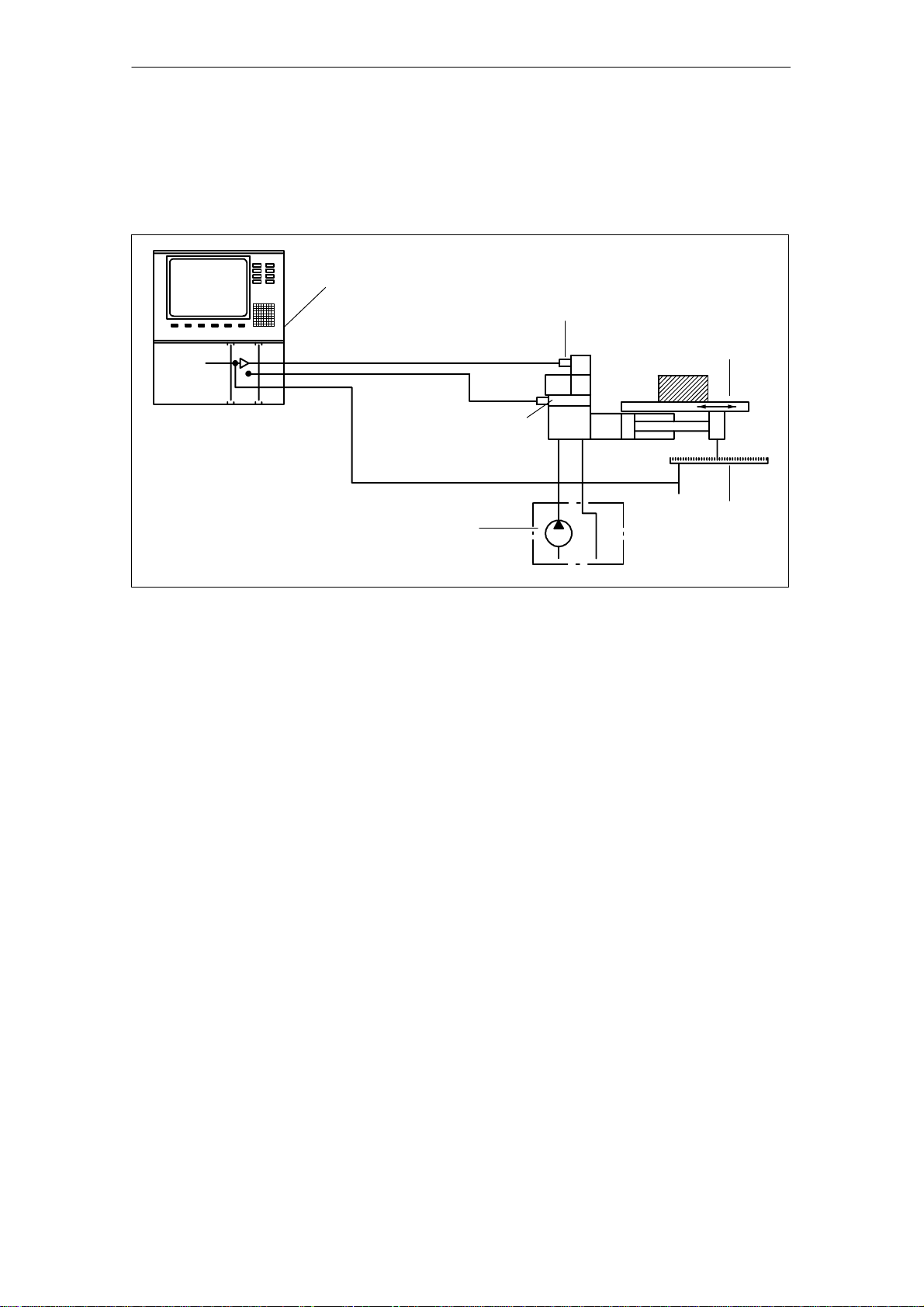
1.3 Structure of an electro-hydraulically controlled drive
axis
SINUMERIK 840D,
SIMODRIVE 611 digital
with HLA module
Shut-off valve
Servo solenoid value with
valve amplifier (OBE)
Machine commutation
02.99
Hydraulic power unit
Fig. 1-1 Construction of an electro-hydraulically controlled drive axis
1.3.1 Machine commutation
Guide mechanism
Friction
Straight line movement of machine slides and tables is accomplished with minimum friction and maximum precision by hydrodynamic and hydrostatic slideways or roller slideways.
A certain degree of friction can be very useful for damping oscillations.
However, excessive friction, especially pronounced transitions from static to
sliding friction, has a negative effect on the control result and impairs control
loop stability.
Position measuring
system
1-16
SINUMERIK 840D/SIMODRIVE 611 digital, HLA Module (FBHLA) – 03.06 Edition
© Siemens AG, 2006. All rights reserved

02.99
1.3.2 Cylinder
1 General Information
1.3 Structure of an electro-hydraulically controlled drive axis
Construction
Quality criteria
The cylinder represents the simplest form of a linear motor and can easily be
integrated into machine guidance. The cylinder normally has a piston rod at one
end.
The following are critical quality criteria
S the surface quality of barrel and piston rod and
S the seals and guides (low-friction, servo quality...).
1.3.3 Control valve
Task
Function
This is the control element in the closed control loop system and forms the electro-hydraulic converter.
The valve steadily converts electrical signals into hydraulic flow.
Its quality is defined by static and dynamic parameters, such as
S zero overlap
S hysteresis
S limit frequency,
etc.
1.3.4 Valve amplifier
This circuit contains the power electronics for the solenoid in the servo solenoid
valve, which adjusts the valve spool position.
The position controller in the valve amplifier (on-board electronics – OBE) controls the position of the valve spool proportionally to the output value
(U=0...10 V).
1.3.5 Shut-off valve
Shut-off valves are used to add safety functions to a valve control with servo
solenoid valve. Shut-off valves can prevent uncontrolled motion of the cylinder.
1.3.6 Position measuring system
Task
The position measuring system supplies the actual value for the position of the
moving machine element.
© Siemens AG, 2006. All rights reserved
SINUMERIK 840D/SIMODRIVE 611 digital, HLA Module (FBHLA) – 03.06 Edition
1-17

1 General Information
1.3 Structure of an electro-hydraulically controlled drive axis
02.99
Function
The velocity is acquired by continuous differentiation of the distance over time.
Various systems are available depending on the level of accuracy required.
Highest accuracy requirements are achieved by digital systems (glass scale
with photoelectric evaluation circuit) mounted directly on the machine.
The most widely used digital incremental systems require a reference point approach at the beginning of a machining operation.
1.3.7 SINUMERIK 840D/SIMODRIVE 611 digital
SINUMERIK control systems and SIMODRIVE drive systems are specially designed for machine tools, manipulators and special-purpose machines.
The numerical control processes the machine program and converts it into control commands. It also monitors command execution continuously.
The control structures for the electro-hydraulic control loop and the interfaces to
S the shut-off valve,
S the servo solenoid valve,
S the position measuring system and
S the central processing unit
are all provided by the HLA module.
The HLA module is an integral component of the SINUMERIK 840D and
SIMODRIVE 611 digital systems.
A range of different modules with graded scope of functions is provided to allow
the SINUMERIK 840D NCU system to be tailored to a wide range of functional
requirements of machines. This allows optimal adaptation to the machine and
machining task, as well as allowing for equipping standardized machine series.
1.3.8 Hydraulic power unit
This unit supplies hydraulic energy.
It is installed remotely from the drive axis. Accumulators are employed to compensate for strongly fluctuating hydraulic energy requirements and to minimize
the installed power.
J
1-18
SINUMERIK 840D/SIMODRIVE 611 digital, HLA Module (FBHLA) – 03.06 Edition
© Siemens AG, 2006. All rights reserved
Configuration
2.1 Configuring steps
2.1.1 Procedure for configuring electrical components
The procedure for configuring an HLA module is divided into steps in such a
way that the user is guided through the full range of relevant settings, from the
required force, to the hydraulics components, and finally the HLA and its encoder evaluation circuitry. This initial configuring phase may be followed by a
second in some cases, in which the corresponding circuit recommendations
and EMC measures are taken into account.
The functions of SIMODRIVE components are described with keywords in this
Planning Guide. Limit values for functions may be specified in some cases.
For further details (e.g. characteristics), please refer to the Installation and
Start-Up Guides for SIMODRIVE 611 digital and SINUMERIK 840 digital.
Further configuring instructions and detailed ordering information can be found
in Catalogs NC 60 and NC Z.
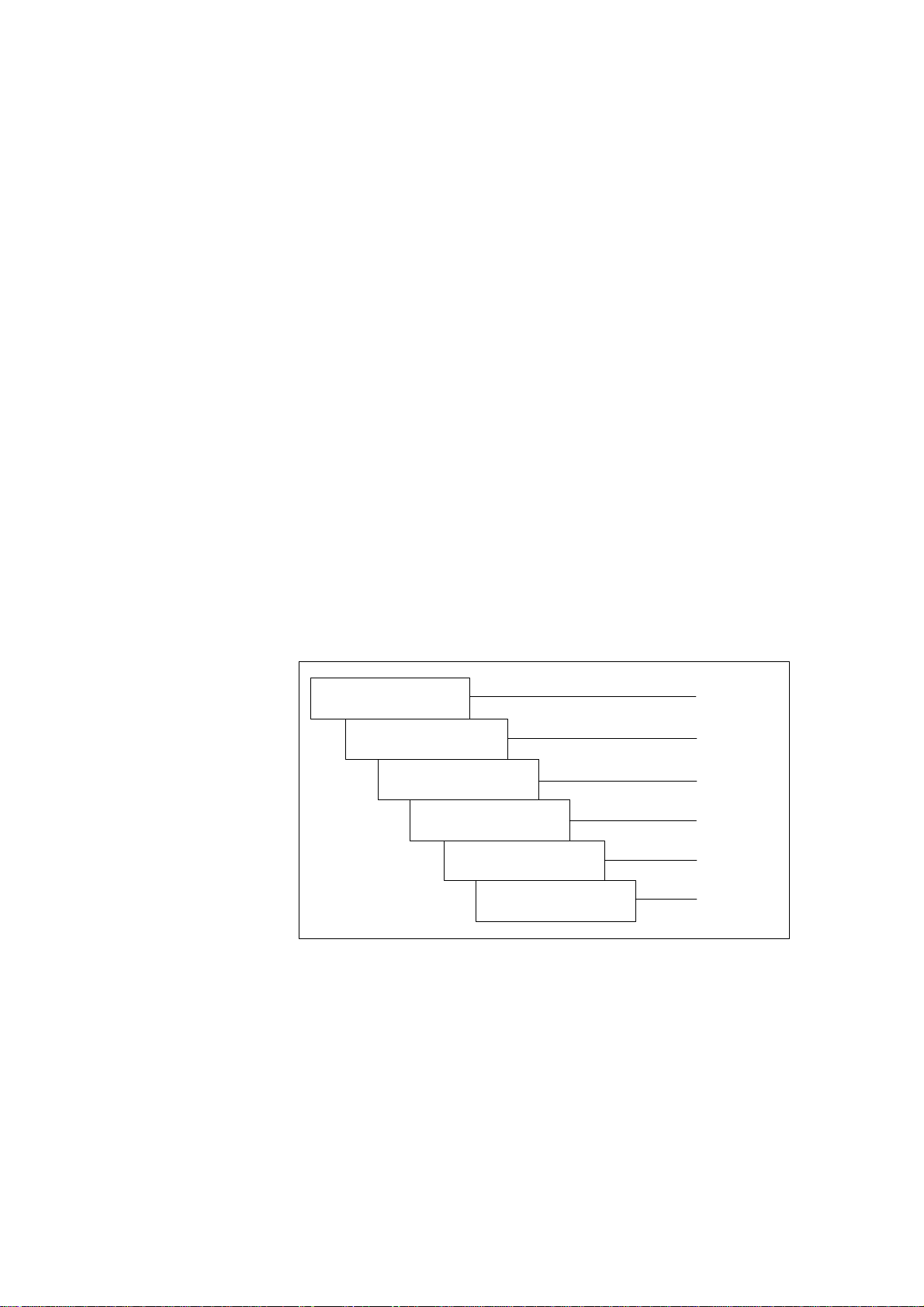
Phase 1
Selection of hydraulic
components
Dimensioning of incoming
mains supply
Dimensioning of
power modules
Dimensioning of external
power supply
Dimensioning of closedloop control components
and publication from Rexroth
and publication 6SN1197-0AA00
and publication 6SN1197-0AA00
2
Section 2.3
Section 2.2
Section 2.2
Section 2.4
Chapter 4
Dimensioning of position
sensor (measuring system)
Fig. 2-1 Configuring steps in start-up sequence
© Siemens AG, 2006. All rights reserved
SINUMERIK 840D/SIMODRIVE 611 digital, HLA Module (FBHLA) – 03.06 Edition
Section 7.1
2-19

2 Confi
g
uration 10.03
2.1 Configuring steps
Phase 2
Recommended circuits
EMC measures
02.99
Section 2.4
Block diagrams/
connection diagrams
Abbreviations,
terms and index
Fig. 2-2 2. Configuring phase
2.1.2 Procedure for configuring hydraulic components
Hydraulically controlled drives are normally configured by the technical sales
and marketing personnel of the hydraulics supplier (e.g. Bosch
Rexroth, see Chapter 8) in close co-operation with the machine manufacturer.
This configuring phase is divided into the following steps:
S Selection of the cylinder on the basis of forces and velocities required and
the cylinder mounting conditions in the machine
(see Subsection 2.3.1).
Section 2.2
Appendix
S Selection of the servo solenoid valves on the basis of the cylinder data,
forces, velocities and dynamic requirements (see Subsection 2.3.2, 2.3.3).
S Selection of the position measuring system and optionally the pressure sen-
sors with regard to the measuring range, accuracy and linearity (see Section
7.1, 7.3).
S Dimensioning of the hydraulic power unit, taking all loads into account (see
Subsection 2.3.5).
S Calculation of the natural frequency of the drive for an initial assessment of
whether the expected control result can be achieved (see Subsection 2.3.4).
S In difficult cases, it may be worthwhile carrying out a dynamic simulation of
the drive as an aid to configuration.
The basic data required to design a system are obtained from a questionnaire.
2-20
SINUMERIK 840D/SIMODRIVE 611 digital, HLA Module (FBHLA) – 03.06 Edition
© Siemens AG, 2006. All rights reserved
02.99
g
2 Confi
uration
2.1 Configuring steps
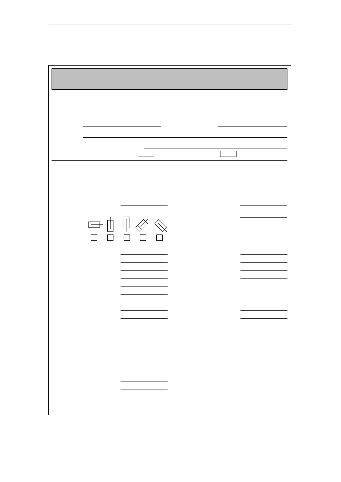
Questionnaire
Design of hydraulic NC axes
Hydraulic NC axes
Design of systems with linear motions
Company:
Address:
Machine:
Axis: Function/designation:
Straight-cut control:
Drive specification
Cylinder dimensions [mm]
Piston diameter:
1. rod diameter:
2. rod diameter:
Stroke:
Cylinder mounting position: Velocity
051-001/
Contact person:
Department:
Phone:
Continuous-path control:
Accuracy requirements
Positioning precision [µm]
from rapid traverse:
from feedrate:
Path accuracy:
tolerance [mm/min]:
Connection: Position
Valve cylinder
Pipe/Hose length [mm]:
Pipe/Hose diameter [mm]:
Moved mass [kg]:
Machining forces [N]
Piston advance:
Piston retraction:
Slide guide friction
µ:
FR [N]:
Pump pressure [bar]:
Velocities [m/min]
Rapid traverse advance:
Rapid traverse retract:
Machining feed advance:
Machining feed retract:
Acceleration rates [m/s2]
Max. acceleration:
Max. delay:
measuring system
Make:
Type:
Other:
Resolution [µm]:
NC control system
Make:
Type:
incremental,
output signal ...
SIEMENS
840D
Processed by: Dept.: No. of pages: Date:
© Siemens AG, 2006. All rights reserved
SINUMERIK 840D/SIMODRIVE 611 digital, HLA Module (FBHLA) – 03.06 Edition
2-21

2 Confi
g
uration
02.99
2.2 Integration in SINUMERIK 840D/SIMODRIVE 611 digital
2.2 Integration in SINUMERIK 840D/SIMODRIVE 611 digital
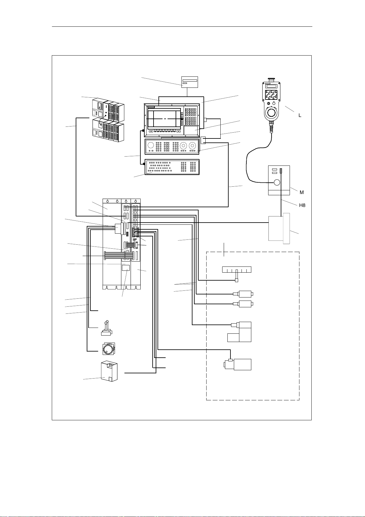
2.2.1 System overview
Components
A complete SINUMERIK 840 digital control system with HLA module consists of
various individual components. These are listed below.
Table 2-1 Components of SINUMERIK 840 digital control with HLA module (number,
No.
in
Fig.
2-3
A NCU box
B NC CPU
component, description)
Component Description
S Enclosure for NC CPU
S Central processing unit of 840D,
S Execution of NC program,
S Contains modules with e.g. PLC, communications
functions
S NCU 573.2 includes a fan module
B1 Cable distributor
1)
C
Operator panel
1)
D
MMC module
S For insertion in NCU
S Display, keyboard, power supply unit and
operator controls for NC
S Operator panel calculator (integrated in panel),
S MMC 103 with hard disk
E Mains supply module
(MS)
1)
F
Machine control panel
G11)ISA adapter
G21)Full keyboard for CNC
Reference: /PJ1/ SIMODRIVE 611
S Machine operation
S Allows AT modules to be used in conjunction with
the MMC module MMC103 (mounted in operator
panel)
S Full keyboard for connection to MMC module
G3 Memory card (PCMCIA)
S Contains the system program,
S can be slotted into the NCU 561.2, 571.2, 572.2,
573.2
G4 Diskette unit (accessory)
H1 to
Cable Reference: /Z/, Catalog of Accessories NC Z
H
9
H10
Cable See Chapter 7, Peripherals/Accessories
to
12
H
I SIMODRIVE hydraulic
module (HLA module)
50 mm carrier module
(universal empty housing)
I1 Phoenix cable connection
S Built-in unit for connection to MMC module
S Closed-loop control of hydraulic drive
S Actuation of servo solenoid valve
Holder for HLA closed-loop control plug-in module
(see Fig. 2-6)
S Shut-off valve
S External 24 V supply
S BERO input
S “Power enable”
J SIMATIC components Reference: /S7H/, Manual
K Terminator Terminator for drive bus (inserted in last module in
drive grouping)
2-22
SINUMERIK 840D/SIMODRIVE 611 digital, HLA Module (FBHLA) – 03.06 Edition
© Siemens AG, 2006. All rights reserved

02.99
2 Configuration10.03
2.2 Integration in SINUMERIK 840D/SIMODRIVE 611 digital
Table 2-1 Components of SINUMERIK 840 digital control with HLA module (number,
No.
in
Fig.
2-3
1)
L
component, description)
Handheld unit
DescriptionComponent
S Connect HHU to K bus via MPI
S Handwheel, EMERGENCY STOP button, key-ac-
tuated switch, override, agreement buttons, dis-
1)
M
Distributor box
play, unassigned keys
S For linking the hand-held unit to the MPI bus
S Connection for EMERGENCY STOP circuit, en-
able keys, handwheel, 24 V DC
N Cable distributor
O Hydraulic drive References:
P External 24 V supply
1) A description of these components can be found in:
References:/BH/, Operator Components Manual
S 24V supply for connection to MPI connector
/BR1/, “Servo solenoid valves” catalog
/BR2/, “Sensors and electronics” catalog
/BR3/, “Adapter plate valves” catalog
S SITOP stabilized power supply modules
Reference: SITOP catalog
Order No. E860060-K2410-A101-A4
Note
An HLA module must never be operated directly on a SIMODRIVE monitoring
module, i.e. it must always be connected via a mains infeed module.
For information about connecting further additional SIMODRIVE monitoring
modules in configurations with several HLA modules, please refer to the
Planning Guide for SIMODRIVE 611 Converters /PJU/.
In a multi-tier configuration, all the infeed supply units must be connected
simultaneously.
© Siemens AG, 2006. All rights reserved
SINUMERIK 840D/SIMODRIVE 611 digital, HLA Module (FBHLA) – 03.06 Edition
2-23
2 Configuration
2.2 Integration in SINUMERIK 840D/SIMODRIVE 611 digital
02.99
Floppy
G4
J
G1
MMC CPU
D
S7–300
C
L
H1
H5
MCP
F
H4
G2
H6
M
E
B
(GND)
H8
B1
G3
Device bus
A
H2
H3
H9
SITOP power
(external PS)
P
MS
module
HLA
NCU
Battery and plug-in fan
unit
Digital I/O
(high-speed NC I/O)
Measurement (2x)
Handwheel
(2x) (1x of M)
External 26.5 V
supply
I1
H10
O
N
K
I
Position sensing
H11
H12
Pressure sensor A
Pressure sensor B
Servo solenoid
valve
BERO
inputs
Enable
Shutoff valve
Note:
Display of hydraulics for one axis
Fig. 2-3 System components
2-24
SINUMERIK 840D/SIMODRIVE 611 digital, HLA Module (FBHLA) – 03.06 Edition
© Siemens AG, 2006. All rights reserved
02.99
2 Configuration
2.2 Integration in SINUMERIK 840D/SIMODRIVE 611 digital
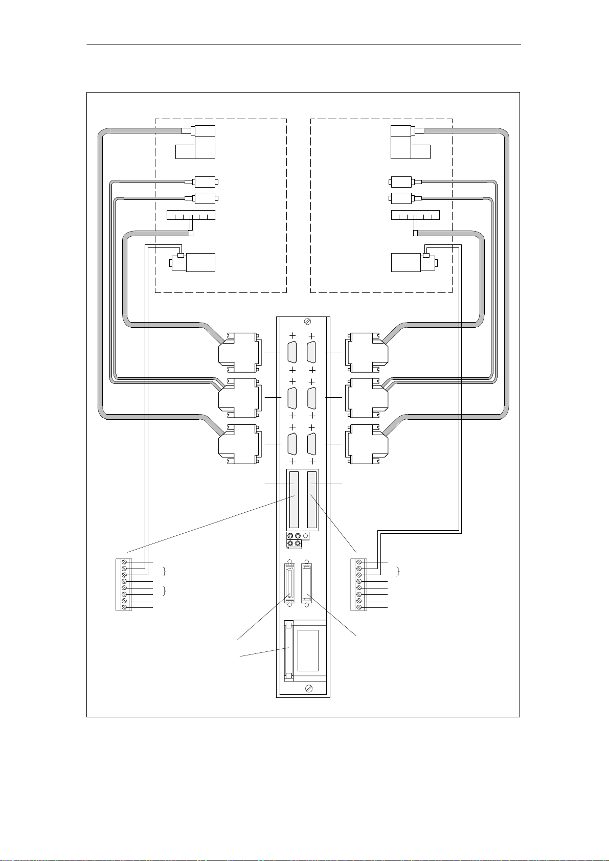
O
B
Hydraulic drive, axis 1
Position
measuring
system
Pressure sensor
Servo solenoid
valve
Pressure
sensor A
Pressure
sensor B
Position sensing
Shutoff valve
Servo solenoid valve
Pressure sensor A
Pressure sensor B
Position sensing
Shutoff valve
O
B
Hydraulic drive, axis 2
–X102
Axis 2
Position
measuring
system
Axis 1
HLA
–X101
BOBB
O
–X111
–X112
Pressure sensor
Servo solenoid
–X121
X431
–X34
M
PV1
MV1
C1
P24
M24
663
9
Functional ground
+
Shutoff valve, axis 1
–
Reserved, do not use!
+
External 26.5 V supply
–
Power enable at term. 663
Internal +24 V enabling voltage
X1141
Drive bus
Device bus interface (X151)
1) Only required if external 26.5 V is not electrically separated safely!
Fig. 2-4 Connection configuration for HLA module
–X35
–X122
X1341
Servo solenoid
valvevalve
X432
M
PV2
MV2
C2
B1
19
B2
9
Functional ground
+
Shutoff valve, axis 2
–
Reserved, do not use!
BERO input, axis 1
Internal 0 V enabling voltage
BERO input, axis 2
Internal +24 V enabling voltage
Drive bus/drive bus terminator on last
module
1)
© Siemens AG, 2006. All rights reserved
SINUMERIK 840D/SIMODRIVE 611 digital, HLA Module (FBHLA) – 03.06 Edition
2-25
2 Configuration
2.2 Integration in SINUMERIK 840D/SIMODRIVE 611 digital
02.99
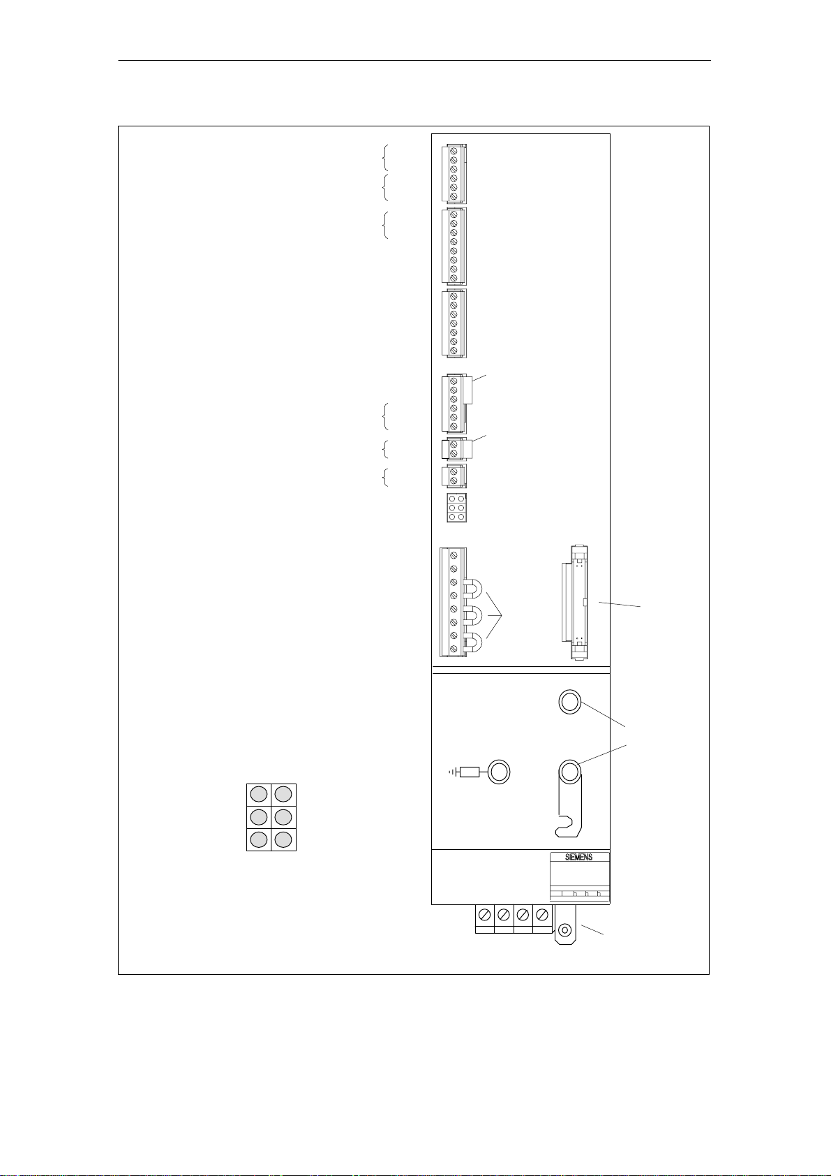
Relay contact,
Ready to operate
message
Relay contact for group message
2
t and motor overtemperature
I
Reference potential for enable voltage
Enabling signal for internal line contactor
Signaling contact for starting lockout (NC contact)
DC link power supply for bridging line failures
Electronics power supply from external source
Electronics power supply from external source
Electronics power supply from external source
Power disable
Enabling voltage
Enabling voltage
Drive enable
P24
P15
N15
N24
M
M
RESET (R+term.15)
Enabling voltage
Setup mode
Contactor energization, start
Signaling contact,
line contactor
NC
contact
NO
contact
74
73.1
73.2
72
5.3
5.2
5.1
63
9
9
64
19
7
45
44
10
15
15
R
9
112
48
111
213
113
NS1
NS2
AS1
AS2
M500
P500
2U1
1U1
2V1
1V1
2W1
1W1
X111
X121
X141
1)
X161
1)
X171
X172
LED displays
X181
1)
X351
Device bus
LED displays
Electronics power
supply faulty
Device is not ready,
no enable signal
(term. 63, 64 or 48)
Line fault
Red
Green
Red
Red
Yellow
Red
5 V voltage level
fault
Device ready
(DC link
precharged)
DC link
overvoltage
1) Jumpers inserted in delivery state
Fig. 2-5 Interfaces on mains supply module (OI and I/RF module)
P600
DC link
connection
M600
Power supply
U1 V1 W1 X131 PE
2-26
SINUMERIK 840D/SIMODRIVE 611 digital, HLA Module (FBHLA) – 03.06 Edition
© Siemens AG, 2006. All rights reserved
02.99
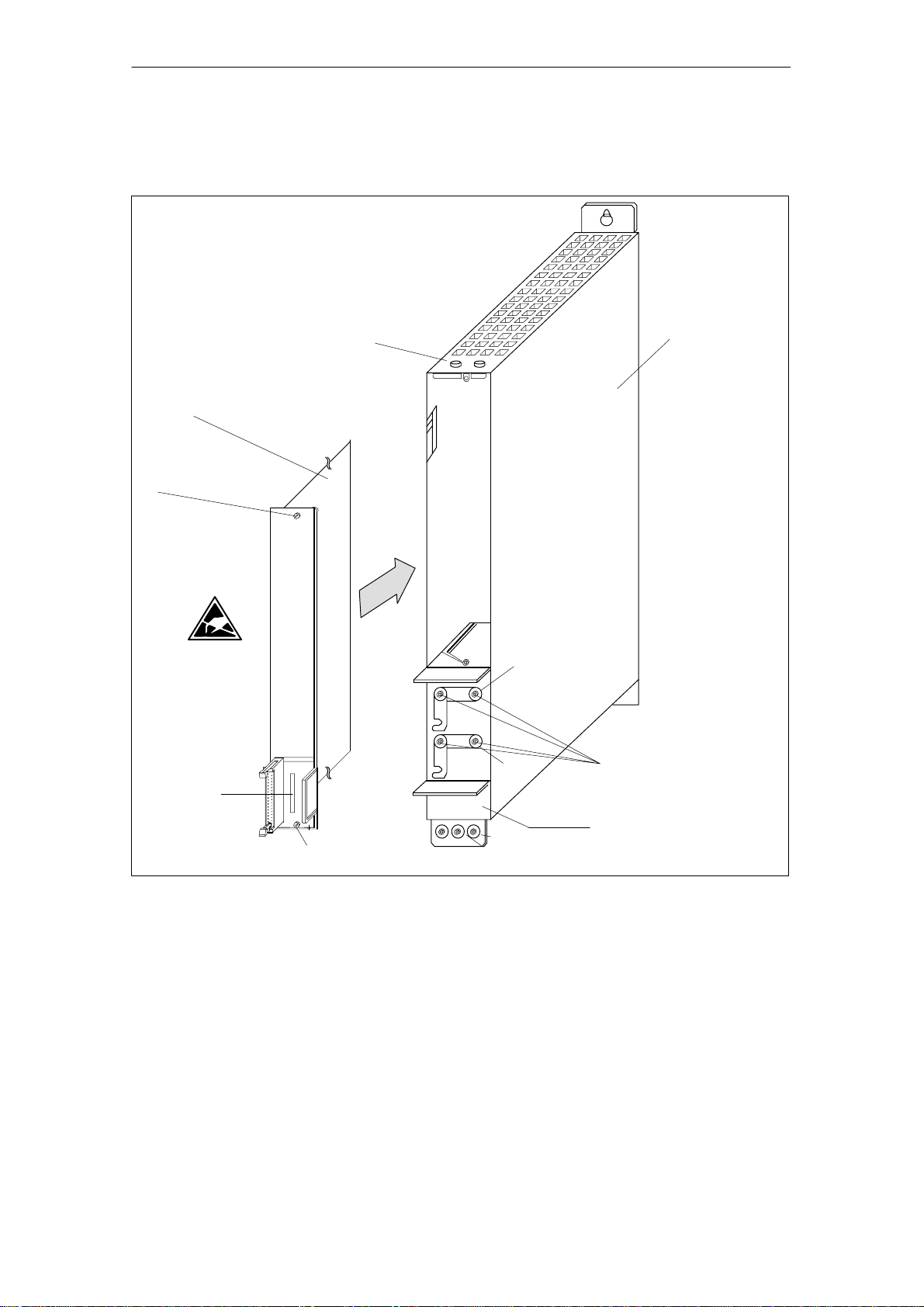
g
Mounting the HLA
closed-loop control
plug-in module
HLA closed-loop control plug-in
module (6SN1115–0BA11–0AA1)
Slotted screw
M3 / 0.8 Nm
2.2 Integration in SINUMERIK 840D/SIMODRIVE 611 digital
Shield connection
2 Confi
50 mm carrier module
(universal empty housing)
(6SN1162–1AA00–0AA0)
uration10.03
P600
M600
Order No.
Slotted screw
M3 / 0.8 Nm
Fig. 2-6 Mounting the HLA closed-loop control plug-in module in 50 mm carrier module (universal empty housing)
PE
M5 / 3.0 Nm
M4 / 1.8 Nm
Rating plate/Order No.
2.2.2 Required FW packages
S SINUMERIK 840D NCK SW 5.1
incl. SIMODRIVE 611 digital HLA module 1.0
S SINUMERIK 840D MMC SW 5.1
or
SINUMERIK 840D HMI SW 6
2.2.3 Hardware requirements
S NCU 561.2, 571.2, 572.2, 573.2
© Siemens AG, 2006. All rights reserved
SINUMERIK 840D/SIMODRIVE 611 digital, HLA Module (FBHLA) – 03.06 Edition
2-27

2 Confi
g
uration 10.03
2.3 Configuring the hydraulic drive
2.3 Configuring the hydraulic drive
02.99
General
information
Hydraulic drives are generally configured by technical sales personnel from the
hydraulics supplier, Rexroth.
The configuration is based on the data from the questionnaire in Subsection
2.1.2.
Please refer to Appendix A for a description of hydraulic components.
The hydraulic drive is configured in the sequence of steps described below.
2.3.1 Cylinder selection
Piston and rod
diameter
The piston and rod diameters are calculated according to Pascal’s theorem on
the basis of the necessary compressive and tensile forces F and a standard
pressure value of P=40...100 bar for machine tools (a maximum pressure setting of 350 bar is permitted).
The force value calculation must include friction and acceleration forces as well
as the actual feed force. Pistons and rods with the following standard diameter
dimensions are available:
Table 2-2 Typical cylinder data
Name
Piston ∅ 25 32 40 50 63 80 100 125
Rod ∅ Standard 12 14 18 22 28 36 45 56
Rod ∅ Optional 18 22 28 36 45 56 70 90
p =
F
A
Diameter
Stroke length
2-28
The stroke is identical to the working stroke of the drive except that it includes a
few additional safety reserves.
SINUMERIK 840D/SIMODRIVE 611 digital, HLA Module (FBHLA) – 03.06 Edition
© Siemens AG, 2006. All rights reserved
02.99
g
2 Confi
uration10.03
2.3 Configuring the hydraulic drive
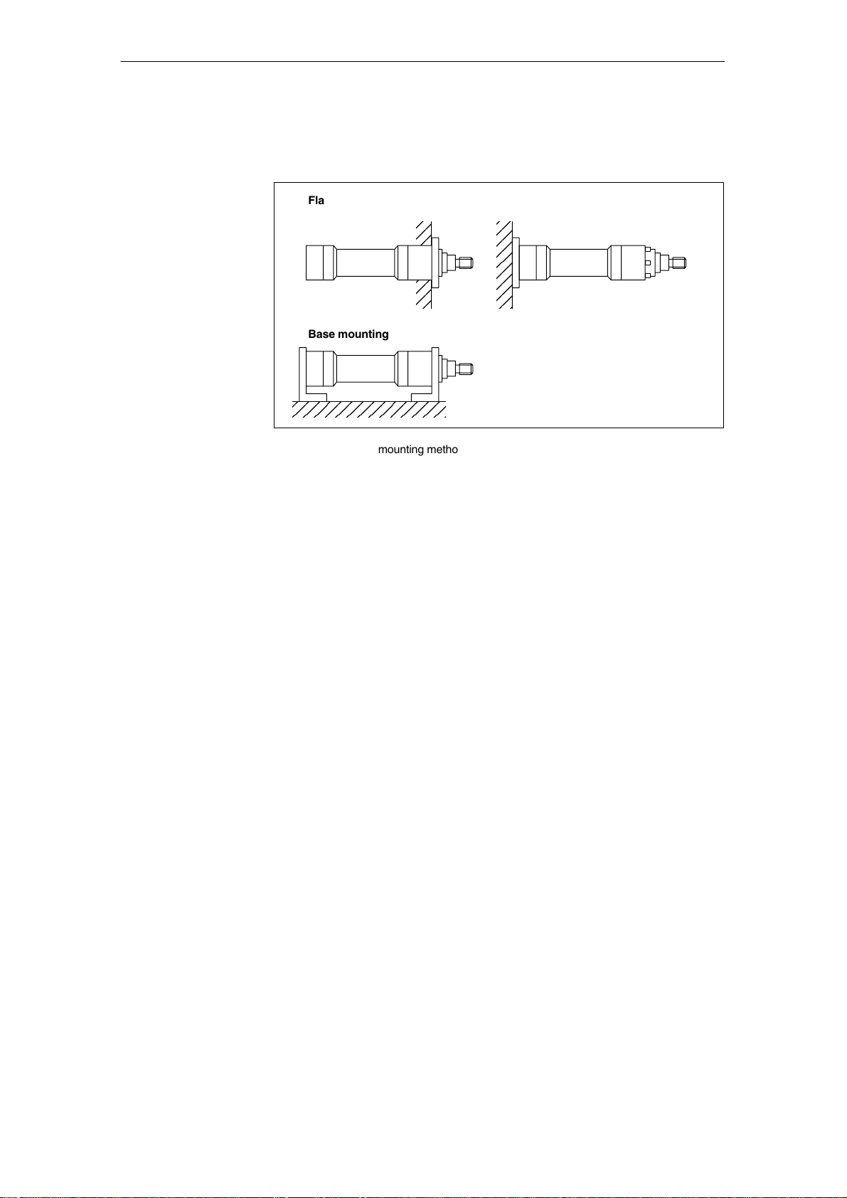
Mounting
Mounting position
In order to ensure good control quality, backlash-free mountings, e.g. base or
flange mountings, must be used.
Flange mounting
Flange at front Flange at rear
Base mounting
Fig. 2-7 Cylinder mounting methods
This will depend on the machine’s situation and affects the choice of shut-off
valves (see Subsection 2.3.3). Vertical loads must be protected via poppet
valves. Forces due to weight must be taken into account in the final calculation
of the operating pressure (MD 5151: CYLINDER_A_ORIENTATION).
See Fig. 4.9 in Chapter 4-17 for the possible cylinder mounting positions.
Seal, friction
Cylinder pipes
Position
measuring system
Suitable seals must be used to minimize friction. Transitions from static to sliding friction have a particularly adverse affect on the control result.
The slide guide friction must be added to the cylinder friction. A friction compensation setting has been provided in the HLA module (MD 5460: FRICTION_COMP_GRADIENT) for the purpose of counteracting initial friction.
The distance between the cylinder and servo solenoid valve must be kept as
short as possible for the sake of the drive’s natural frequency (compressibility of
the oil volume). In ideal cases, the servo solenoid valve is flange-mounted directly on the cylinder.
The incremental and absolute position measuring systems supported by the
HLA module are mounted on the machine slide. It is also possible to use position measuring systems (SSI encoders) integrated in the cylinder.
© Siemens AG, 2006. All rights reserved
SINUMERIK 840D/SIMODRIVE 611 digital, HLA Module (FBHLA) – 03.06 Edition
2-29
2 Confi
g
uration 10.03
2.3 Configuring the hydraulic drive
2.3.2 Selection of servo solenoid valves
Reference: /BR1/, “Servo solenoid valves” catalog
02.99
Valve types
(overview)
The HLA module supports servo solenoid valves with on-board electronics
(OBE) supplied by Bosch Rexroth AG. The technical data for these valves and
valves supplied by other manufacturers is stored in the HLA module software.
The drive is parameterized automatically when the order number is entered.
The following table lists the various types of servo solenoid valve and HR servo
solenoid valves (HR = High Response) available from Bosch Rexroth AG.
For a complete list, please see Tables 2-4 to 2-10.
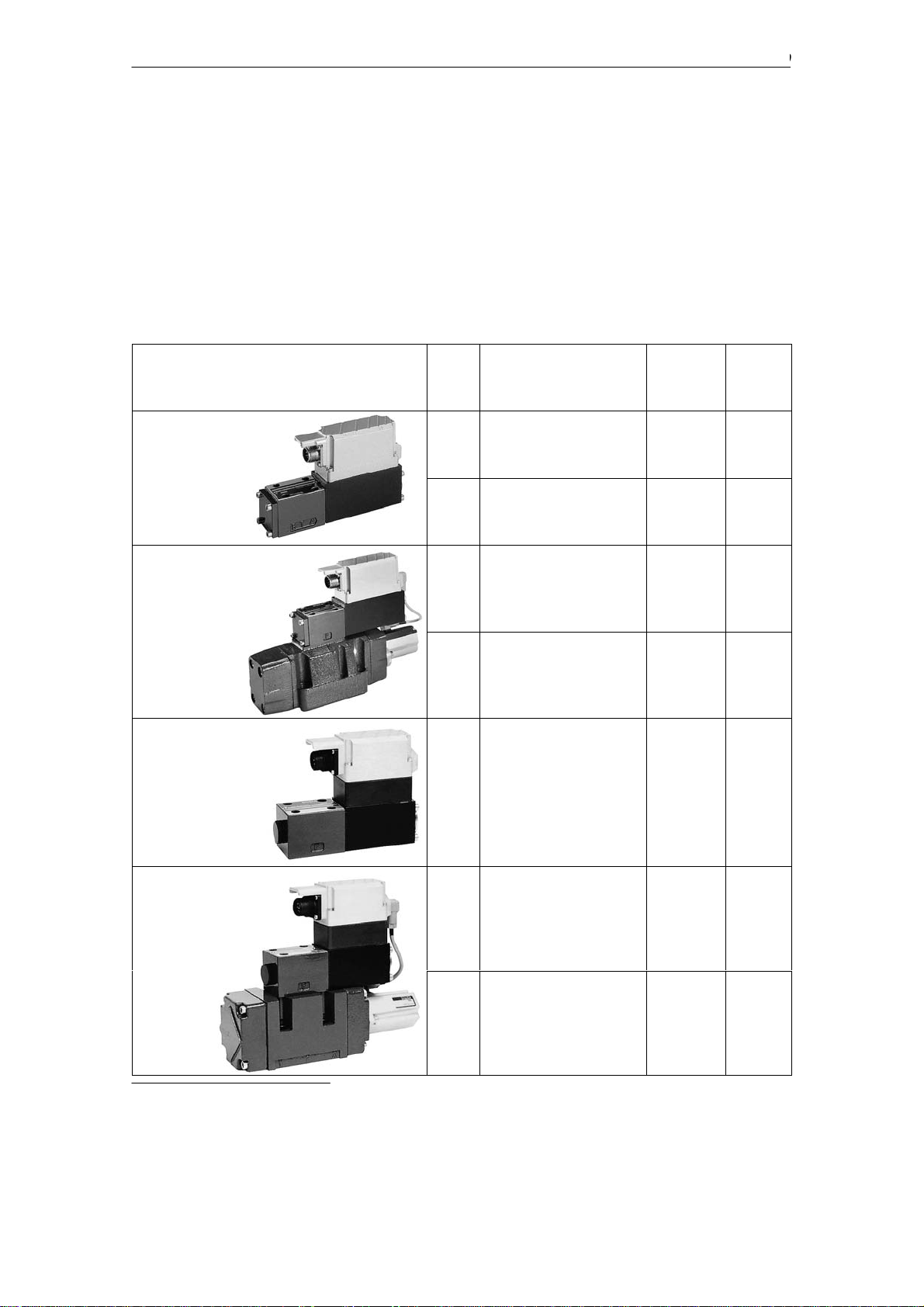
Table 2-3 Overview of servo solenoid and HR servo solenoid valves from Bosch Rexroth AG
Description
4WRPEH
(directly-controlled
servo solenoid valve)
4WRPE
(pilot-controlled servo
solenoid valve)
Nomi-
nal
size
6 up to 40 / 35 bar linear and
10 up to 100 / 35 bar linear and
10 up to 70 / 5 bar with knee 40
16 up to 150 / 5 bar with knee 40
Nominal flowrate (l/min)
for nominal pressure drop
per control edge (bar)
Character-
istic
with knee
with knee
Limit fre-
quency
1)
(Hz)
110
85
4WRPEH
(directly-controlled
HR servo solenoid valve)
4WRVE
(pilot-controlled
HR servo solenoid valve)
1) The characteristic values specified for the valve limit frequencies relate to an amplitude of 5% and a
phase offset in the Bode diagram of –90°, see also data in catalog supplied by Bosch Rexroth AG.
6 up to 40 / 35 bar linear and
with knee
10 up to 70 / 35 bar with knee 80
16 up to 150 / 5 bar with knee 80
210
2-30
SINUMERIK 840D/SIMODRIVE 611 digital, HLA Module (FBHLA) – 03.06 Edition
© Siemens AG, 2006. All rights reserved
 Loading...