

Page 1
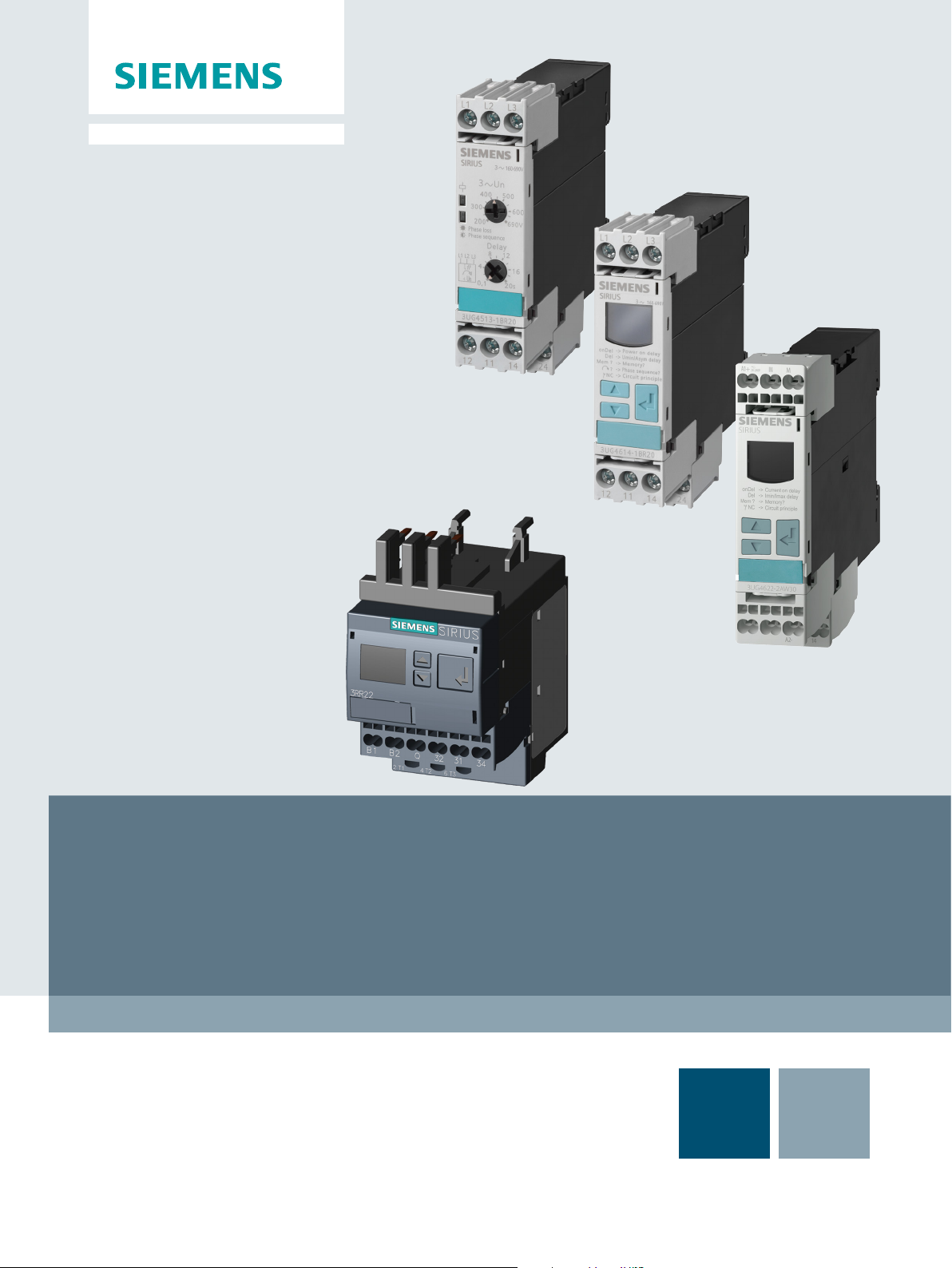
Industrial Controls
Monitoring and Control Devices
3UG4 / 3RR2 Monitoring Relays
GerätehandbuchManual
Edition
05/2016
siemens.com
Page 2

Page 3

3UG4 / 3RR2 monitoring relays
___________________
___________________
___________________
___________________
___________________
___________________
___________________
___________________
___________________
Industrial Controls
Monitoring and control devices
3UG4 / 3RR2 monitoring relays
Manual
05/2016
NEB927043002000/RS
Introduction
1
Safety information
2
System overview
3
3RR2 current monitoring
relays
4
3UG4501 filling level
monitoring relay
5
3UG4.1 line monitoring relay
6
3UG4621/3UG4622 current
monitoring relays
7
3UG4625 residual current
monitoring relay with 3UL23
transformer
8
3UG458. insulation
monitoring relay.
9
3UG463. voltage monitoring
relay
10
3UG4641 cos phi and active
current monitoring relay
11
3UG4651 speed monitoring
relay
12
Accessories
13
References
A
Parameters
B
Dimension Drawings
C
Menu-based operation
D
-AC/004
Page 4
Siemens AG
Division Digital Factory
Postfach 48 48
90026 NÜRNBERG
GERMANY
3ZX1012-0UG40-0AC0
Ⓟ
Copyright © Siemens AG 2011.
All rights reserved
Legal information
Warning notice system
DANGER
indicates that death or severe personal injury will result if proper precautions are not taken.
WARNING
indicates that death or severe personal injury may result if proper precautions are not taken.
CAUTION
indicates that minor personal injury can result if proper precautions are not taken.
NOTICE
indicates that property damage can result if proper precautions are not taken.
Qualified Personnel
personnel qualified
Proper use of Siemens products
WARNING
Siemens products may only be used for the applications described in the catalog and in the relevant technical
maintenance are required to ensure that the products operate safely and without any problems. The permissible
ambient conditions must be complied with. The information in the relevant documentation must be observed.
Trademarks
Disclaimer of Liability
This manual contains notices you have to observe in order to ensure your personal safety, as well as to prevent
damage to property. The notices referring to your personal safety are highlighted in the manual by a safety alert
symbol, notices referring only to property damage have no safety alert symbol. These notices shown below are
graded according to the degree of danger.
If more than one degree of danger is present, the warning notice representing the highest degree of danger will
be used. A notice warning of injury to persons with a safety alert symbol may also include a warning relating to
property damage.
The product/system described in this documentation may be operated only by
task in accordance with the relevant documentation, in particular its warning notices and safety instructions.
Qualified personnel are those who, based on their training and experience, are capable of identifying risks and
avoiding potential hazards when working with these products/systems.
Note the following:
documentation. If products and components from other manufacturers are used, these must be recommended
or approved by Siemens. Proper transport, storage, installation, assembly, commissioning, operation and
All names identified by ® are registered trademarks of Siemens AG. The remaining trademarks in this publication
may be trademarks whose use by third parties for their own purposes could violate the rights of the owner.
We have reviewed the contents of this publication to ensure consistency with the hardware and software
described. Since variance cannot be precluded entirely, we cannot guarantee full consistency. However, the
information in this publication is reviewed regularly and any necessary corrections are included in subsequent
editions.
for the specific
05/2016 Subject to change
Page 5

Table of contents
1 Introduction................................................................................................................................. 11
2 Safety information ....................................................................................................................... 17
3 System overview ......................................................................................................................... 19
4 3RR2 current monitoring relays ..................................................................................................... 45
1.1 Service&Support ............................................................................................................... 11
1.2 Technical data in Siemens Industry Online Support ........................................................... 14
1.3 DataMatrix code ................................................................................................................ 15
2.1 Standards.......................................................................................................................... 17
2.2 Product-specific safety information .................................................................................... 18
2.3 Approvals, test certificates, characteristics ......................................................................... 18
3.1 Product description ............................................................................................................ 19
3.2 Application planning .......................................................................................................... 20
3.3 Connection methods.......................................................................................................... 21
3.3.1 Screw-type connection ...................................................................................................... 21
3.3.2 Spring-loaded connection .................................................................................................. 23
3.3.3 Device replacement by means of removable terminals ....................................................... 28
3.4 Mounting / removal ............................................................................................................ 29
3.4.1 Mounting 3RR2 current monitoring relay ............................................................................ 29
3.4.2 Mounting the 3UG4 monitoring relay .................................................................................. 34
3.4.3 Installing the 3UG458. monitoring relay. ............................................................................ 35
3.5 Overview of the functions .................................................................................................. 36
3.5.1 3RR2 current monitoring relays ......................................................................................... 36
3.5.2 3UG45 / 3UG46 monitoring relays ..................................................................................... 37
3.6 Menu-based operation ....................................................................................................... 39
4.1 Product description ............................................................................................................ 45
4.2 Application areas ............................................................................................................... 47
4.3 Performance features of current monitoring relays ............................................................. 48
4.3.1 General data ..................................................................................................................... 49
4.3.2 Properties.......................................................................................................................... 50
4.3.3 Configuration of load feeders ............................................................................................. 51
4.3.4 Combinations with 3RT20 contactor .................................................................................. 52
4.4 3RR21 current monitoring relays ....................................................................................... 53
4.4.1 Operator controls and connection terminals ....................................................................... 53
4.4.2 Function ............................................................................................................................ 54
4.4.3 Operation .......................................................................................................................... 56
4.4.4 Diagnostics ....................................................................................................................... 58
4.4.5 Circuit diagrams ................................................................................................................ 59
3UG4 / 3RR2 monitoring relays
Manual, 05/2016, NEB927043002000/RS-AC/004
5
Page 6

Table of contents
5 3UG4501 filling level monitoring relay ............................................................................................ 89
6 3UG4.1 line monitoring relay ....................................................................................................... 101
4.4.6 Technical data ....................................................................................................................60
4.5 3RR22 current monitoring relays ........................................................................................70
4.5.1 Operator controls and connection terminals ........................................................................70
4.5.2 Function .............................................................................................................................71
4.5.3 Operation ...........................................................................................................................75
4.5.4 Diagnostics ........................................................................................................................77
4.5.5 Circuit diagrams .................................................................................................................78
4.5.6 Technical data ....................................................................................................................79
5.1 Application areas ................................................................................................................89
5.2 Operator controls and connection terminals ........................................................................90
5.3 Functions ...........................................................................................................................91
5.4 Operation ...........................................................................................................................94
5.5 Diagnostics ........................................................................................................................94
5.5.1 Diagnostics with LED .........................................................................................................94
5.6 Circuit diagrams .................................................................................................................95
5.7 Technical data ....................................................................................................................96
6.1 Application areas ..............................................................................................................102
6.2 3UG4511 line monitoring relay .........................................................................................103
6.2.1 Operator controls and connection terminals ......................................................................103
6.2.2 Function ...........................................................................................................................104
6.2.3 Diagnostics ......................................................................................................................105
6.2.3.1 Diagnostics with LED .......................................................................................................105
6.2.4 Circuit diagrams ...............................................................................................................106
6.2.5 Technical data ..................................................................................................................107
6.3 3UG4512 line monitoring relay .........................................................................................111
6.3.1 Operator controls and connection terminals ......................................................................111
6.3.2 Function ...........................................................................................................................112
6.3.3 Diagnostics ......................................................................................................................114
6.3.3.1 Diagnostics with LED .......................................................................................................114
6.3.4 Circuit diagrams ...............................................................................................................115
6.3.5 Technical data ..................................................................................................................116
6.4 3UG4513 line monitoring relay .........................................................................................121
6.4.1 Operator controls and connection terminals ......................................................................121
6.4.2 Function ...........................................................................................................................122
6.4.3 Operation .........................................................................................................................124
6.4.4 Diagnostics ......................................................................................................................125
6.4.4.1 Diagnostics with LED .......................................................................................................125
6.4.5 Circuit diagrams ...............................................................................................................126
6.4.6 Technical data ..................................................................................................................127
6.5 3UG4614 line monitoring relay .........................................................................................131
6.5.1 Operator controls and connection terminals ......................................................................131
6.5.2 Functions .........................................................................................................................132
6.5.3 Operation .........................................................................................................................135
3UG4 / 3RR2 monitoring relays
6 Manual, 05/2016, NEB927043002000/RS-AC/004
Page 7

Table of contents
7 3UG4621/3UG4622 current monitoring relays ............................................................................... 173
8 3UG4625 residual current monitoring relay with 3UL23 transformer ................................................. 191
6.5.4 Diagnostics ..................................................................................................................... 136
6.5.4.1 Indications on the display ................................................................................................ 136
6.5.4.2 Reset .............................................................................................................................. 137
6.5.5 Circuit diagrams .............................................................................................................. 137
6.5.6 Technical data ................................................................................................................. 138
6.6 3UG4615 / 3UG4616 line monitoring relays ..................................................................... 142
6.6.1 Operator controls and connection terminals ..................................................................... 142
6.6.2 Functions ........................................................................................................................ 143
6.6.3 Operation ........................................................................................................................ 146
6.6.4 Diagnostics ..................................................................................................................... 147
6.6.4.1 Indications on the display ................................................................................................ 147
6.6.4.2 Reset .............................................................................................................................. 149
6.6.5 Circuit diagrams .............................................................................................................. 150
6.6.6 Technical data ................................................................................................................. 151
6.7 3UG4617 / 3UG4618 line monitoring relays ..................................................................... 156
6.7.1 Operator controls and connection terminals ..................................................................... 156
6.7.2 Functions ........................................................................................................................ 157
6.7.3 Operation ........................................................................................................................ 161
6.7.4 Diagnostics ..................................................................................................................... 162
6.7.4.1 Indications on the display ................................................................................................ 162
6.7.4.2 Reset .............................................................................................................................. 164
6.7.5 Circuit diagrams .............................................................................................................. 165
6.7.5.1 Internal circuit diagrams................................................................................................... 165
6.7.5.2 Wiring examples .............................................................................................................. 166
6.7.6 Technical data ................................................................................................................. 167
7.1 Application areas ............................................................................................................. 173
7.2 Operator controls and connection terminals ..................................................................... 174
7.3 Functions ........................................................................................................................ 175
7.4 Operation ........................................................................................................................ 179
7.5 Diagnostics ..................................................................................................................... 180
7.5.1 Indications on the display ................................................................................................ 180
7.5.2 Reset .............................................................................................................................. 181
7.6 Circuit diagrams .............................................................................................................. 182
7.6.1 Internal circuit diagrams................................................................................................... 182
7.6.2 Wiring examples (3UG46..-.AW30) .................................................................................. 182
7.6.3 Wiring examples (3UG462.-.AA30) .................................................................................. 183
7.7 Technical data ................................................................................................................. 184
8.1 Application areas ............................................................................................................. 191
8.2 Operator controls and connection terminals ..................................................................... 192
8.3 Functions ........................................................................................................................ 193
8.4 Operation ........................................................................................................................ 202
8.5 Diagnostics ..................................................................................................................... 203
3UG4 / 3RR2 monitoring relays
Manual, 05/2016, NEB927043002000/RS-AC/004
7
Page 8

Table of contents
9 3UG458. insulation monitoring relay ............................................................................................. 213
10 3UG463. voltage monitoring relay ................................................................................................ 271
8.5.1 Indications on the display .................................................................................................203
8.5.2 Reset ...............................................................................................................................205
8.6 Circuit diagrams ...............................................................................................................206
8.6.1 Internal circuit diagrams ...................................................................................................206
8.6.2 Wiring examples ...............................................................................................................207
8.7 Technical data ..................................................................................................................208
9.1 Application areas ..............................................................................................................215
9.2 Performance features of the insulation monitoring relays ..................................................216
9.3 3UG4581 insulation monitoring relay ................................................................................218
9.3.1 Operator controls and connection terminals ......................................................................218
9.3.2 Functions .........................................................................................................................219
9.3.3 Operator control ...............................................................................................................224
9.3.4 Diagnostics ......................................................................................................................226
9.3.4.1 Diagnostics with LEDs ......................................................................................................226
9.3.5 Circuit diagrams ...............................................................................................................227
9.3.5.1 Internal circuit diagrams ...................................................................................................227
9.3.6 Characteristics .................................................................................................................231
9.3.7 Technical data ..................................................................................................................233
9.4 3UG4582/3UG4583 insulation monitoring relays...............................................................235
9.4.1 Operator controls and connection terminals ......................................................................235
9.4.2 Functions .........................................................................................................................238
9.4.2.1 Function diagrams ............................................................................................................243
9.4.3 Operator control ...............................................................................................................249
9.4.4 Diagnostics ......................................................................................................................253
9.4.4.1 Diagnostics with LEDs ......................................................................................................253
9.4.5 Circuit diagrams ...............................................................................................................255
9.4.5.1 Internal circuit diagrams ...................................................................................................255
9.4.5.2 Wiring examples ...............................................................................................................256
9.4.6 Characteristics .................................................................................................................261
9.4.7 Technical data ..................................................................................................................265
9.4.7.1 3UG4582 .........................................................................................................................265
9.4.7.2 3UG4583 .........................................................................................................................269
10.1 Application areas ..............................................................................................................271
10.2 3UG4631 / 3UG4632 voltage monitoring relay ..................................................................272
10.2.1 Operator controls and connection terminals ......................................................................272
10.2.2 Functions .........................................................................................................................273
10.3 3UG4633 voltage monitoring relay ....................................................................................275
10.3.1 Operator controls and connection terminals ......................................................................275
10.3.2 Functions .........................................................................................................................276
10.4 Operation .........................................................................................................................278
10.5 Diagnostics ......................................................................................................................279
10.5.1 Indications on the display .................................................................................................279
10.5.2 Reset ...............................................................................................................................280
3UG4 / 3RR2 monitoring relays
8 Manual, 05/2016, NEB927043002000/RS-AC/004
Page 9

Table of contents
11 3UG4641 cos phi and active current monitoring relay .................................................................... 289
12 3UG4651 speed monitoring relay ................................................................................................ 307
13 Accessories .............................................................................................................................. 323
10.6 Circuit diagrams .............................................................................................................. 281
10.6.1 Internal circuit diagrams................................................................................................... 281
10.6.2 Wiring examples .............................................................................................................. 282
10.7 Technical data ................................................................................................................. 283
11.1 Application areas ............................................................................................................. 289
11.2 Operator controls and connection terminals ..................................................................... 290
11.3 Functions ........................................................................................................................ 291
11.4 Operation ........................................................................................................................ 296
11.5 Diagnostics ..................................................................................................................... 297
11.5.1 Indications on the display ................................................................................................ 297
11.5.2 Reset .............................................................................................................................. 298
11.6 Circuit diagrams .............................................................................................................. 299
11.6.1 Internal circuit diagrams................................................................................................... 299
11.6.2 Wiring examples .............................................................................................................. 300
11.7 Technical data ................................................................................................................. 302
12.1 Application areas ............................................................................................................. 307
12.2 Operator controls and connection terminals ..................................................................... 308
12.3 Functions ........................................................................................................................ 309
12.4 Operation ........................................................................................................................ 312
12.5 Diagnostics ..................................................................................................................... 313
12.5.1 Indications on the display ................................................................................................ 313
12.5.2 Reset .............................................................................................................................. 314
12.6 Circuit diagrams .............................................................................................................. 315
12.6.1 Internal circuit diagrams................................................................................................... 315
12.6.2 Wiring examples .............................................................................................................. 316
12.7 Technical data ................................................................................................................. 317
13.1 Accessories for 3RR2 current monitoring relays ............................................................... 323
13.1.1 Sealable cover ................................................................................................................ 323
13.1.2 Terminal support for stand-alone assembly...................................................................... 324
13.2 Accessories for 3UG4 monitoring relays .......................................................................... 327
13.2.1 Sealable cover ................................................................................................................ 327
13.2.2 Push-in lugs .................................................................................................................... 328
13.2.3 Probes for the 3UG4501 monitoring relay ........................................................................ 329
13.2.4 Summation current transformer for the 3UG4624 monitoring relay ................................... 332
13.2.5 3UL23 residual current transformers for 3UG4625 monitoring relays................................ 333
13.2.5.1 General information ......................................................................................................... 333
13.2.5.2 Installation specifications ................................................................................................. 335
13.2.5.3 Potential for optimization ................................................................................................. 339
13.2.5.4 Installation faults.............................................................................................................. 341
3UG4 / 3RR2 monitoring relays
Manual, 05/2016, NEB927043002000/RS-AC/004
9
Page 10

Table of contents
A References ............................................................................................................................... 361
B Parameters ............................................................................................................................... 363
C Dimension Drawings .................................................................................................................. 375
D Menu-based operation ................................................................................................................ 389
Index ........................................................................................................................................ 407
13.2.5.5 Internal circuit diagram .....................................................................................................343
13.2.5.6 Installing ...........................................................................................................................344
13.2.5.7 Technical data ..................................................................................................................346
13.2.5.8 Dimension drawings .........................................................................................................348
13.3 Accessories for 3UG458. insulation monitoring relays. ......................................................352
13.3.1 Sealable cover .................................................................................................................352
13.3.2 3UG4983 upstream module for the 3UG4583 monitoring relay .........................................353
13.3.2.1 Internal circuit diagrams ...................................................................................................355
13.3.2.2 Technical data ..................................................................................................................358
C.1 Dimension drawings 3RR2 monitoring relay......................................................................375
C.2 Dimension drawings 3UG4 monitoring relays ....................................................................383
C.2.1 Dimension drawings 3UG4 monitoring relays. (2 connecting terminals) .............................383
C.2.2 Dimension drawings 3UG4 monitoring relays. (3 connecting terminals) .............................384
C.2.3 Dimension drawings 3UG4 monitoring relays. (4 connecting terminals) .............................385
C.2.4 Dimension drawings 3UG458 insulation monitoring relay. (3UG4983 upstream
module) ............................................................................................................................387
3UG4 / 3RR2 monitoring relays
10 Manual, 05/2016, NEB927043002000/RS-AC/004
Page 11

1
Purpose of the manual
Required basic knowledge
Scope of the manual
1.1
Service&Support
Online Support
Links:
This manual describes the 3UG4 monitoring relays for stand-alone assembly and the 3RR2
current monitoring relays for mounting on 3RT2 contactors
The manual provides overview information for integrating the monitoring relays into the
system environment, and it describes the hardware and software components of the devices.
The information in this manual enables you to commission the monitoring relays.
To understand these operating instructions you should have a general knowledge of
automation engineering and low-voltage switchgear.
The manual is valid for these monitoring relays. It contains a description of the devices that
is valid at the time of publication.
The Online Support in the Service&Support portal is an extensive information system for all
questions relating to Siemens products and solutions. This service enables direct and central
access to in-depth information concerning the products, systems and applications for
industry and to a large number of programming, configuration and application examples. Its
content is available via a mobile app.
The Technical Forum of the Online Support provides the opportunity for users to swap
information. Support Request allows contact to be established with Siemens experts in
Technical Support.
Siemens Industry Online Support ensures that users in industry are always kept up-to-date
with news, software updates and announcements by means of newsletters and Twitter.
(http://support.automation.siemens.com/WW/view/en/16605022)
Service&Support Portal (http://support.automation.siemens.com), Online Support
3UG4 / 3RR2 monitoring relays
Manual, 05/2016, NEB927043002000/RS-AC/004
11
Page 12

Introduction
Product Support
Link:
CAx data
Link:
1.1 Service&Support
Are you looking for product information such as technical data, updates or FAQs? Here, the
"Product Support" section of the Service & Support Portal offers an extensive collection of all
information about the Siemens Industry Automation and Drive Technologies products and
solutions:
● Answers to frequently asked questions (FAQs)
● Updates/upgrades, service packs and support tools for downloading
● Manuals and operating instructions
● Technical data/CAx data
● Approvals and certificates
● Test certificates and characteristic curves
All Product Support information is at your disposal free of charge and around the clock, and
you always get the current version.
Product Support (http://support.automation.siemens.com/WW/view/en/4000024)
The CAx Download Manager provides you with a simple means of gaining access to up-todate product data for your CAx or CAe system.
You configure your own download package with just a few clicks. You can choose from the
following information for products
● Product images
● 2D dimensional drawings
● 3D models
● Internal circuit diagrams
● EPLAN macro files
● Manuals
● Characteristics
● Operating instructions
● Certificates
● Product master data
CAx Download Manager
(http://support.automation.siemens.com/WW/view/en/42455541)
3UG4 / 3RR2 monitoring relays
12 Manual, 05/2016, NEB927043002000/RS-AC/004
Page 13

Introduction
Applications & Tools
Link:
My Documentation Manager
Link:
Reference
1.1 Service&Support
Applications & Tools supports you with various tools and examples when it comes to solving
your automation tasks. Solutions are presented in interaction with several components in the
system, without focusing on individual products.
● Application examples
● Function blocks & tools
● Background and system descriptions
● Performance statements
● Demonstration systems/videos
Applications & Tools (http://support.automation.siemens.com/WW/view/en/20208582)
My Documentation Manager enables you to compile your own documentation from our
standard documents (manuals), which are located in the Product Support section. Under
mySupport, you have the opportunity to create and manage you own compilations in a
structure of their own.
MyDocumentationManager (http://support.automation.siemens.com/WW/view/en/38715968)
You can find further information on structure and navigation in Online Support here
(http://support.automation.siemens.com/WW/view/en/11774658).
3UG4 / 3RR2 monitoring relays
Manual, 05/2016, NEB927043002000/RS-AC/004
13
Page 14
Introduction
1.2
Technical data in Siemens Industry Online Support
Technical data sheet
Compare products
Further documentation
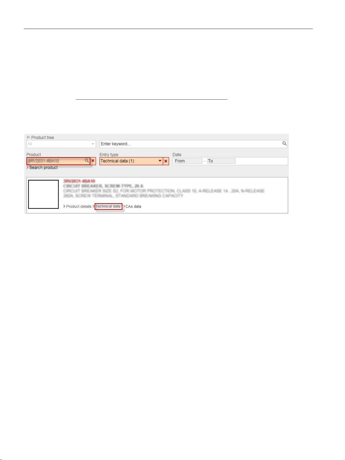
1.2 Technical data in Siemens Industry Online Support
You can find all the technical data of the product in the Siemens Industry Online Support
(https://support.industry.siemens.com/cs/ww/en/ps/16364/td).
1. Enter the full article number of the desired device in the "Product" field, and confirm with
the Enter key.
2. Click the "Technical data link.
You can compare the technical data of the products in Siemens Industry Online Support.
1. Select the products you want to compare.
2. Click the "Compare technical data" button.
To install and connect the monitoring relays, you require the operating instructions of the
monitoring relays used.
The Appendix "References (Page 361)" has a list of the operating instructions.
3UG4 / 3RR2 monitoring relays
14 Manual, 05/2016, NEB927043002000/RS-AC/004
Page 15

Introduction
1.3
DataMatrix code
1P Article
number
+ S Location
Date
Serial number
Data
identifier
User
content
Separator
User content
Separator
User content
User content
Note
The information content is displayed without spaces.
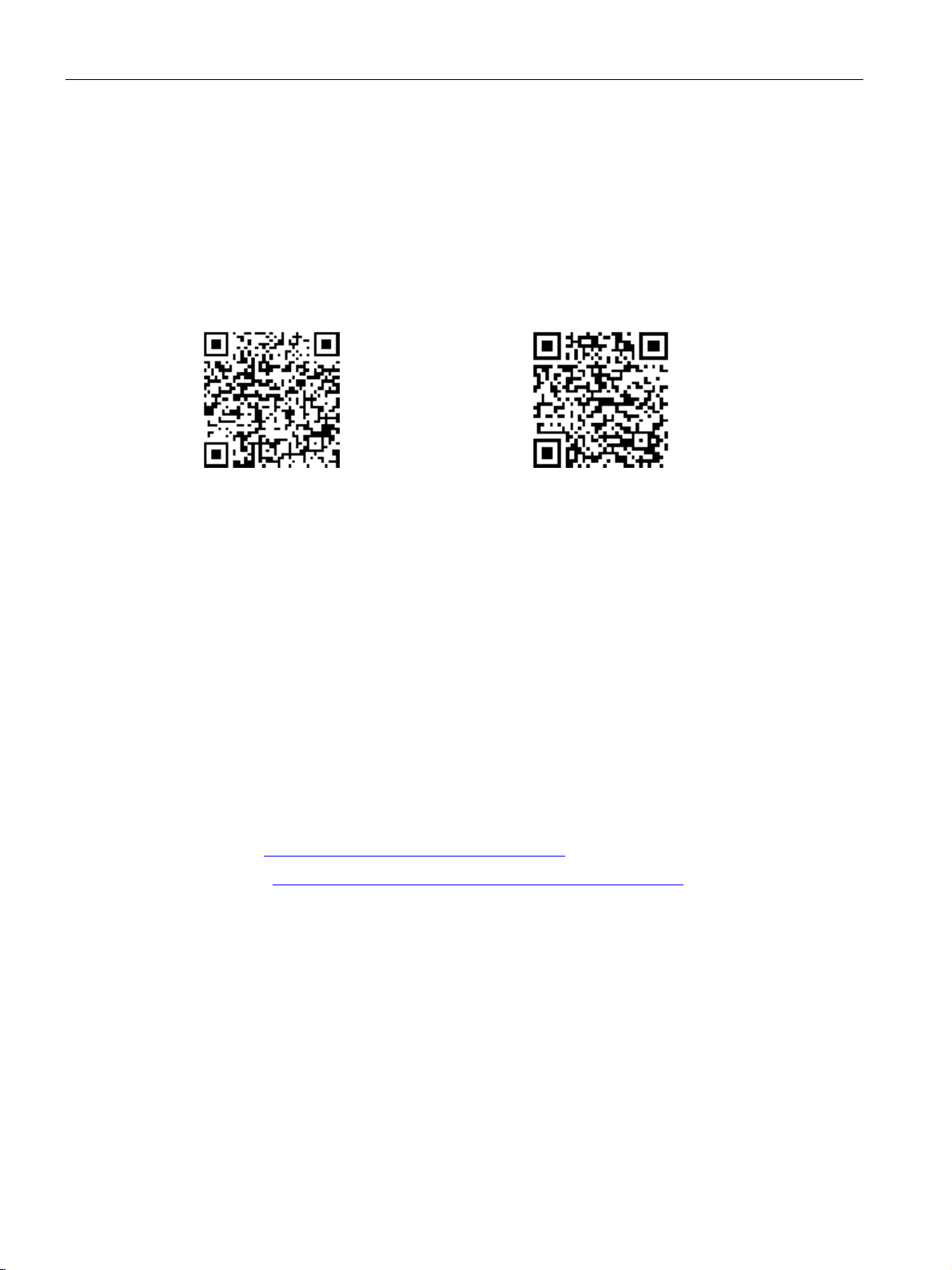
1.3 DataMatrix code
A DataMatrix code is lasered onto all 3UG4/3RR2 monitoring relay devices underneath the
label.
The DataMatrix codes are standardized in ISO/IEC 16022. The DataMatrix codes on
Siemens devices use ECC200 coding for powerful error correction.
The following device information is encoded in the DataMatrix codes as a bit stream:
● Article number
● Serial number
● If applicable, MAC address
This information is stored in the following format in the DataMatrix code:
/
This machine-readable information simplifies and accelerates handling of the respective
devices.
As well as fast access to the serial numbers of the respective devices for unique
identification, the DataMatrix codes simplify communication with Siemens Technical Support.
3UG4 / 3RR2 monitoring relays
Manual, 05/2016, NEB927043002000/RS-AC/004
15
Page 16
Introduction
SIEMENS Industry Support App
Link for Android
Link for iOS
Recycling and disposal
Up-to-the-minute information
Technical Assistance:
or on the Internet at:
1.3 DataMatrix code
DataMatrix codes primarily enable extremely fast and convenient access to all devicespecific information relating to an article number in the SIEMENS Service&Support Portal,
such as operating instructions, manuals, data sheets, FAQs, etc.
We provide the SIEMENS Industry Support app free for this purpose and it can be used on
most commercially available smartphones and tablets.
The SIEMENS Industry Support app is available for iOS and Android-based devices and can
be accessed via the following links:
These devices can be recycled thanks to their low pollutant content. For environmentallyfriendly recycling and disposal of your electronic waste, please contact a company certified
for the disposal of electronic waste.
You can obtain further assistance by calling the following numbers:
Telephone: +49 (911) 895-5900 (8 a.m. to 5 p.m. CET)
Fax: +49 (911) 895-5907
E-mail: (mailto:technical-assistance@siemens.com)
Internet: (www.siemens.com/industrial-controls/technical-assistance)
3UG4 / 3RR2 monitoring relays
16 Manual, 05/2016, NEB927043002000/RS-AC/004
Page 17

2
2.1
Standards
Applicable standards
Part 2: Additional requirements
Monitoring relays are safe to touch in accordance with IEC / EN 60529.
1)
interference. Users may have to take suitable measures.
Reference
The monitoring relays comply with the following standards:
Table 2- 1 Standards - monitoring relays
Device standards
EMC standard1)
Resistance to
extreme climates
Touch protection
• IEC / EN 60947-1 "Low-voltage switchgear and controlgear: General rules"
• IEC / EN 60947-4-1 "Contactors and motor-starters: Electromechanical
contactors and motor-starters"
• IEC / EN 60947-5-1 "Control circuit devices and switching elements:
Electromechanical control circuit devices";
VDE 0660 "Low-voltage switchgear"
• IEC / EN 61557-8 "Equipment for testing, measuring or monitoring of
protective measures - Electrical safety in low voltage distribution systems
up to 1000 V AC and 1500 V DC, Part 8: Insulation monitoring devices for
IT systems".
• DIN EN 50042 "Terminal marking"
• DIN EN 61869-2 "Instrument transformers -
for current transformers"
• IEC / EN 61000-6-2 "Generic standards - Immunity for industrial
environments"
• IEC / EN 61000-6-4 "Generic standards - Emission standard for industrial
environments"
• IEC 60721-3-3 "Classification of environmental conditions"
The monitoring relays are climate-proof according to IEC 60721-3.
• IEC / EN 60529 "Degrees of protection provided by enclosures"
This is a device of Class A. When used in domestic areas, the device can cause radio
SIRIUS components have been approved by a whole range of bodies for various sectors
(shipbuilding, etc.). An up-to-date list of approvals appears in Chapter 10 of the Catalog
IC 10 - SIRIUS "Industrial Controls" (www.siemens.com/industrial-controls/catalogs), and
more information, as well as an option to download certificates, can be obtained on the
Internet (www.siemens.com/automation/csi_en).
3UG4 / 3RR2 monitoring relays
Manual, 05/2016, NEB927043002000/RS-AC/004
17
Page 18
Safety information
2.2
Product-specific safety information
Intended use
WARNING
Intended use
Can Cause Death, Serious Injury, or Property Damage.
Hazardous Voltage
WARNING
Hazardous Voltage.
Radio interference
Note
The devices have been built as Class
Use of these devices in domestic areas can result in radio interference!
2.3
Approvals, test certificates, characteristics
Approvals, test certificates, characteristics
2.2 Product-specific safety information
The devices may only be used for the applications described in the catalog and the
technical description, and only in conjunction with equipment or components from other
manufacturers which have been approved or recommended by Siemens.
This product can function correctly and reliably only if it is transported, stored, assembled,
and installed correctly, and operated and maintained as recommended.
Before you run any sample programs or programs that you have written yourself, make
sure that running the plant cannot cause injury to anyone else or damage to the machine
itself.
Will cause death or serious injury.
Turn off and lock out all power supplying this device before working on this device.
A devices.
3UG4 / 3RR2 monitoring relays
18 Manual, 05/2016, NEB927043002000/RS-AC/004
You can find an overview of the certifications available for low-voltage controls and
distribution products and other technical documentation, updated daily, on the Internet
(www.siemens.com/industrial-controls/support).
You will find further information in the Catalog IC 10 - SIRIUS "Industrial Controls," Chapter
10 (www.siemens.com/industrial-controls/catalogs).
Page 19

3
3.1
Product description
Product description
The tried and tested SIRIUS monitoring relays for electrical and mechanical quantities
enable constant monitoring of all important characteristic quantities that provide information
about the reliability performance of the plant. Sudden disturbances and gradual changes,
which may reveal a maintenance requirement, for example, are both indicated. By means of
relay outputs, the monitoring relays enable direct shutdown of the affected sections of the
plant as well as issuing an alarm (e.g. by switching on a warning lamp). To respond flexibly
to short-term disturbances such as voltage dips or load variation, the monitoring relays have
settable delay times. This avoids unnecessary alarming and shutdowns while enhancing
plant availability.
The individual 3UG4 monitoring relays offer the following functions in various combinations:
● Undershoot and/or overshoot of liquid levels
● Phase sequence
● Phase failure, neutral failure
● Phase asymmetry
● Undershoot and/or overshoot of voltage thresholds
● Undershoot and/or overshoot of current thresholds
● Undershoot and/or overshoot of power factor thresholds
● Monitoring of the active current or apparent current
● Monitoring of the fault current
● Monitoring the insulation resistance
● Undershoot and/or overshoot of speed thresholds
The 3RT2 contactors for mounting on 3RR2 current monitoring relays offer:
● Phase sequence
● Phase failure
● Undershoot and/or overshoot of current thresholds
● Monitoring of the active current or apparent current
● Monitoring of the fault current
3UG4 / 3RR2 monitoring relays
Manual, 05/2016, NEB927043002000/RS-AC/004
19
Page 20

System overview
3.2
Application planning
Installation altitude
Operating conditions and resistance to extreme climates
Special application environments
3.2 Application planning
The following information must be taken into account when planning applications involving
the SIRIUS monitoring relays.
The monitoring relays are approved for installation altitudes up to 2,000 m. The reduced air
density at altitudes higher than 2,000 meters affects the electrical characteristics of the
monitoring relays. The reduction factors which have to be taken into account when using
monitoring relays at altitudes higher than 2,000 m can be obtained on request on the Internet
(www.siemens.com/automation/csi_en).
The monitoring relays are climate-proof. They are intended for use in enclosed spaces in
which no severe operating conditions prevail (e.g. dust, caustic vapors, hazardous gases).
Appropriate measures must be taken when installing in areas subject to dust and humidity.
Condensation on the devices is not permissible.
The SIRIUS devices have been approved by a whole range of bodies for various sectors
(shipbuilding, etc.). An up-to-date list of approvals is provided in Chapter 10 of the Catalog
IC 10 - SIRIUS "Industrial Controls." You will find more information and an option to
download certificates on the Internet (www.siemens.com/automation/csi_en).
3UG4 / 3RR2 monitoring relays
20 Manual, 05/2016, NEB927043002000/RS-AC/004
Page 21
System overview
3.3
Connection methods
3.3.1
Screw-type connection
Screw-type connection
Connection cross-sections of the removable terminal blocks with screw-type connections
Removable terminal
1 x (0.5 to 4) mm²
AWG
2 x (20 to 14)
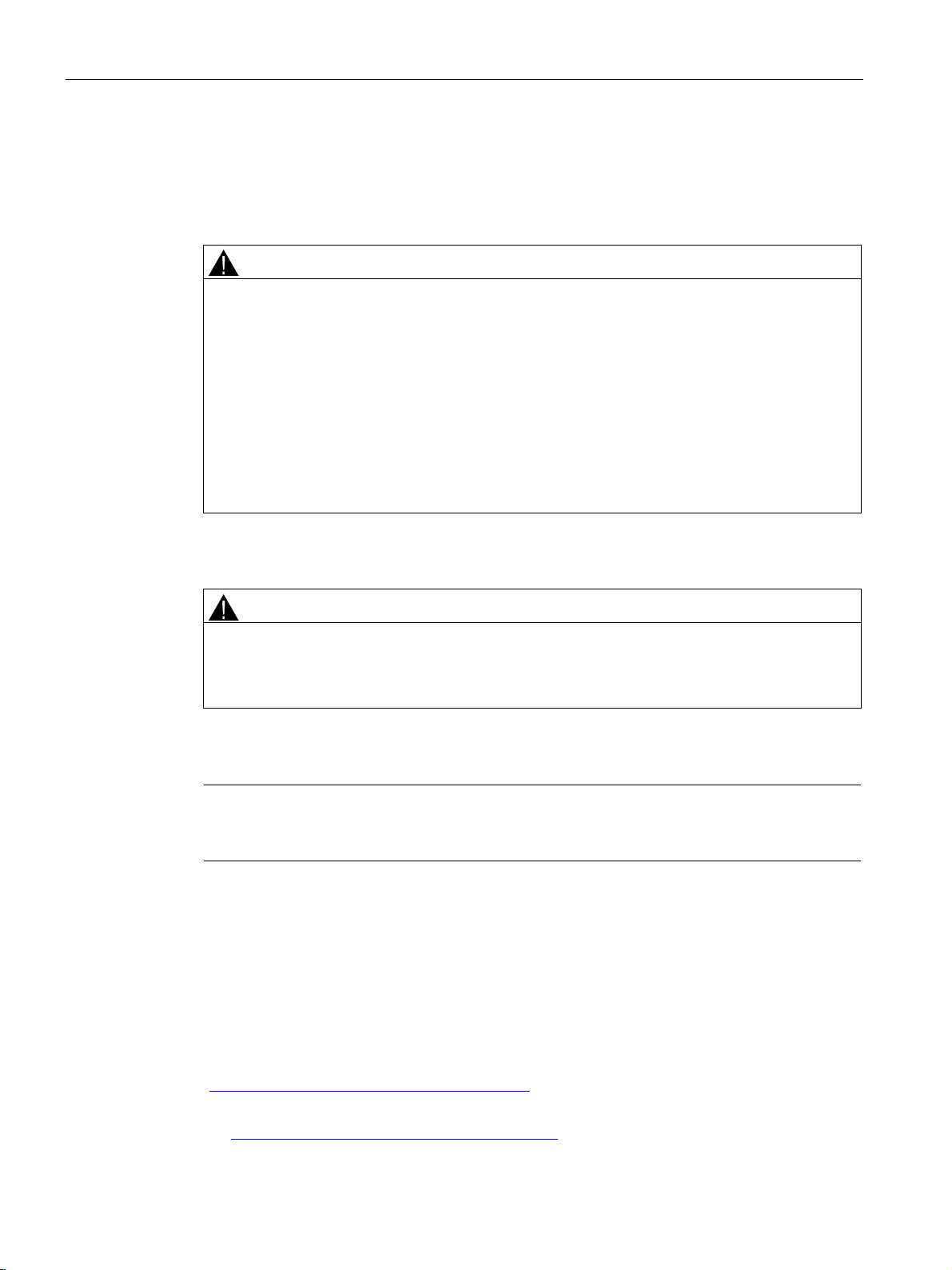
3.3 Connection methods
Use the following tool to establish the connection: All SIRIUS monitoring relays feature
size PZ 2 screws for Pozidriv screwdrivers.
The devices have screw terminals with captive screws and washers. The screw terminals
also allow for the connection of 2 conductors with different cross-sections.
Table 3- 1 Removable terminal block with screw-type connections - monitoring relays
Tool
Tightening torque 0.8 to 1.2 Nm
Solid and stranded
Finely stranded without end sleeve
Finely stranded with end sleeve
Pozidriv size PZ 2, Ø 5 to 6 mm
2 x (0.5 to 2.5) mm²
---
1 x (0.5 to 2.5) mm²
2 x (0.5 to 1.5) mm²
3UG4 / 3RR2 monitoring relays
Manual, 05/2016, NEB927043002000/RS-AC/004
21
Page 22
System overview
Connection cross-sections of the permanently connected terminal blocks with screw-type connections
Permanently connected terminal
Size S00
Size S0
Size S2
Tightening torque
0.8 to 1.2 Nm
2 - 2.5 Nm
3 to 4.5 Nm (27 to 40 lb.in)
2 x (0.5 to 1.5) mm²
2 x (1 to 2.5) mm²
2 x (1.0 to 35 mm²)
2 x (0.75 to 2.5) mm²
2 x (0.5 to 1.5) mm²
2 x (1 to 2.5) mm²
2 x (1.0 to 25 mm²)
2 x (2.5 to 6) mm²
max. 1 x 10 mm²
2 x (20 to 14)
2 x (16 to 12)
2 x (18 to 2)
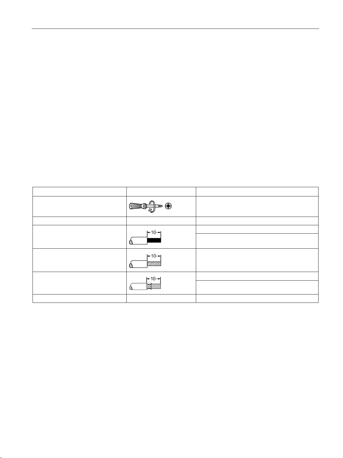
3.3 Connection methods
The following table lists the permissible conductor cross-sections for the main conductor
connections of 3RR2 current monitoring relays with analog and digital setting (size S00, S0
and S2) with screw-type connections.
Table 3- 2 Permanently connected terminal block with screw-type connection - Main conductor terminals of the 3RR2
current monitoring relays
Tool
Solid and stranded
Finely stranded
without end sleeve
Finely stranded
with end sleeve
AWG
Pozidriv size PZ 2,
Ø 5 to 6 mm
max. 2 x (1 ... 4) mm²
--- --- ---
2 x (0.75 to 2.5) mm²
1 x 12 2 x (14 to 8) 1 x (18 to 1)
Pozidriv size PZ 2,
Ø 5 to 6 mm
2 x (2.5 to 10) mm² 1 x (1.0 to 50 mm²)
Pozidriv size PZ 2
Ø 5 to 6 mm
1 x (1.0 to 35 mm²)
3UG4 / 3RR2 monitoring relays
22 Manual, 05/2016, NEB927043002000/RS-AC/004
Page 23
System overview
3.3.2
Spring-loaded connection
Spring-loaded connection
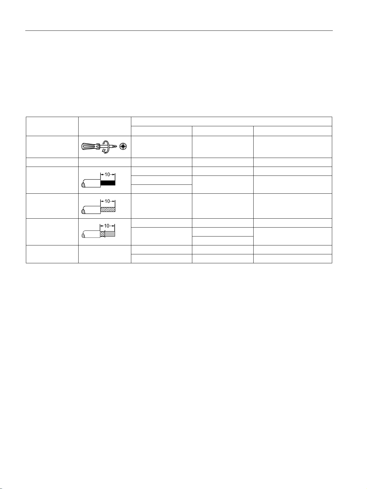
①
Solid
②
Finely stranded
③
Stranded
④
Finely stranded with end sleeve
a
Spring-loaded terminal
b
Busbar
3.3 Connection methods
All SIRIUS monitoring relays have spring-loaded connections. They make wiring quick and
maintenance-free, while also meeting high demands in terms of vibration and shock
resistance. If the cross-section of a connectable wire is greater than 6 mm², the forces
required for operation of the tension spring are so high that the spring-loaded connection can
no longer be used in a problem-free manner. For this reason, size S2 current monitoring
relays are only offered with screw-type or spring-loaded terminals in the control circuit. The
terminals of the main current paths are always screw-type terminals.
Image 3-1 Spring-loaded terminal
The conductors can be clamped directly or you can pre-treat them to add a form of splice
protection. This could involve attaching end sleeves or pin cable lugs to the ends of the
conductors; the tidiest solution is to use conductors whose ends have been sealed by means
of ultrasound.
3UG4 / 3RR2 monitoring relays
Manual, 05/2016, NEB927043002000/RS-AC/004
23
Page 24

System overview
3.3 Connection methods
The devices are equipped with a two-wire terminal, i.e. two independent connections for
each current path (exception: in the case of 3RR2, terminals of the main current paths have
one clamping point). Just one conductor is connected to each clamping point. The springloaded terminal presses the conductor against the busbar, which curves around inside the
terminal. The high contact pressure per unit area achieved in this way is gas-tight. The
spring-loaded terminal presses flat against the conductor, but does not damage it. The
spring force of the spring-loaded terminal has been dimensioned such that the clamping
force adjusts to the conductor diameter automatically. This ensures that any conductor
deformation caused by settling, creepage, or yielding is compensated for. The clamping
point cannot become loose of its own accord. This connection is vibration- and shock-proof.
Vibrations or shocks will not damage the conductor, nor will they cause contact separation.
These terminals are particularly well suited for use with machines and systems which are
subject to stresses such as these, e.g. vibrators, rail vehicles, and elevators.
The contact pressure between the conductor and the busbar is set to an optimum level, so
this clamp connection is appropriate for high-voltage applications, as well as for transferring
voltages and currents in the mV or mA range within instrumentation and electronic
components.
A standardized screwdriver (3 mm slot; 3RA2908-1A) is offered in the Catalog IC10
"Industrial Controls" (www.siemens.com/industrial-controls/catalogs) as an actuation tool for
opening the spring-loaded terminals.
3UG4 / 3RR2 monitoring relays
24 Manual, 05/2016, NEB927043002000/RS-AC/004
Page 25
System overview
Spring-loaded connection for mountable 3RR2 current monitoring relays
DANGER
Hazardous Voltage.
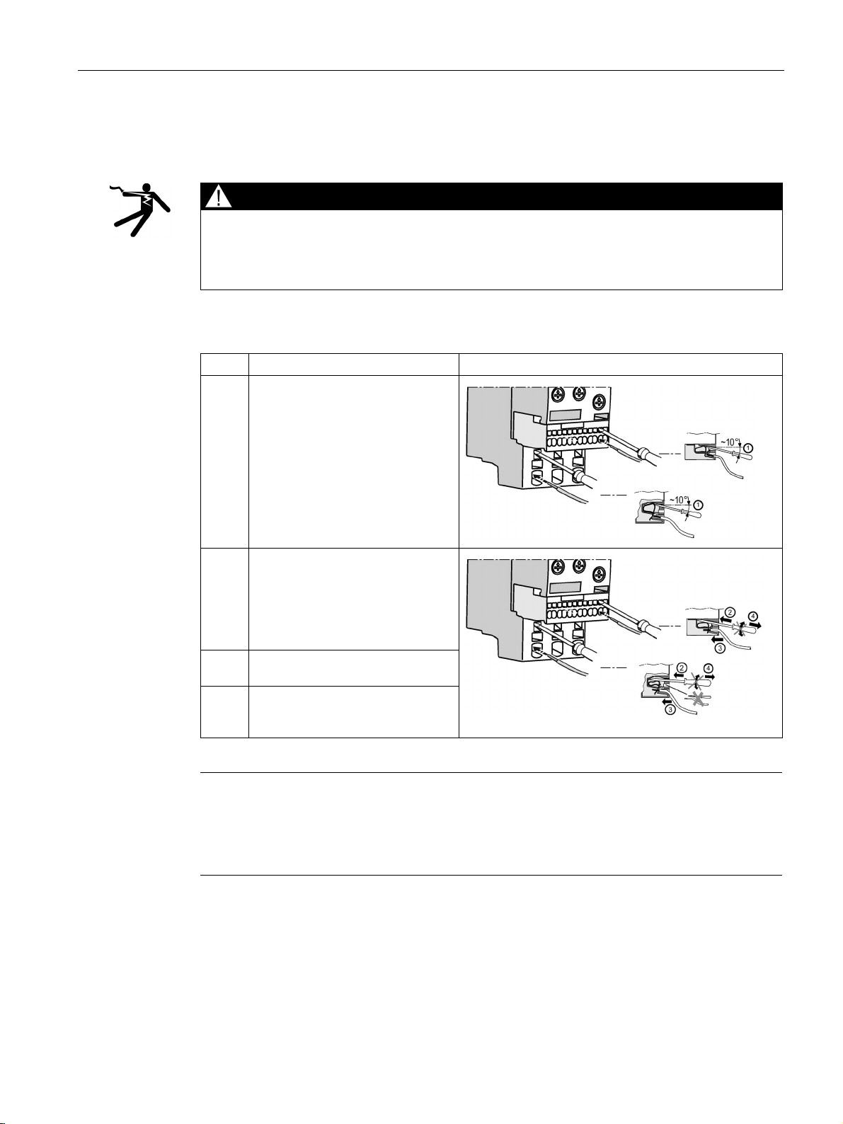
Step
Instructions
Figure
automatically.
connection slot.
is now securely clamped.
Note
Damage to spring-loaded terminal on the 3RR2 current monitoring relay!
If you insert the screwdriver into the central opening (main circuit S00 and S0 only) on the
spring
Do not insert the screwdriver into the central opening on the spring-loaded terminal.
3.3 Connection methods
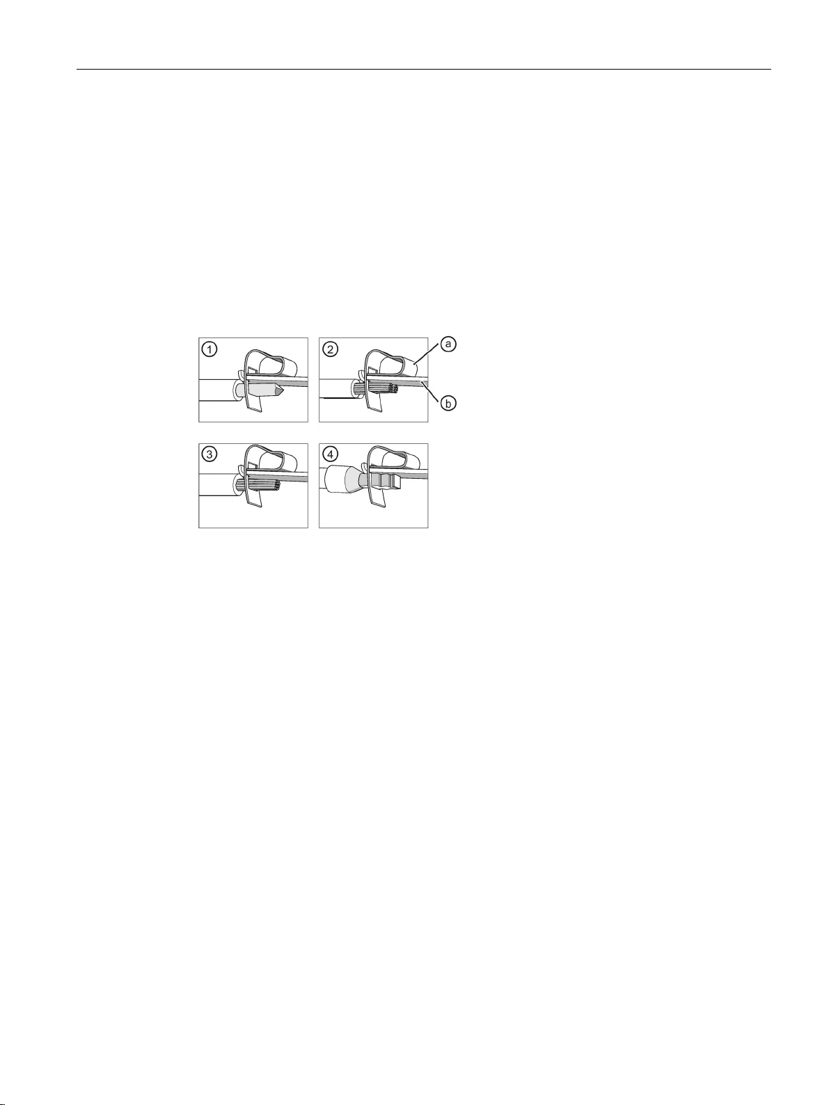
The table below describes the procedure for creating a spring-loaded connection:
Will cause death or serious injury.
Turn off and lock out all power supplying this device before working on this device.
Table 3- 3 Connecting the 3RR2 current monitoring relay spring-loaded terminal
1 Insert the screwdriver into the
respective operating slot.
2 Press the screwdriver down, then
push it into the operating slot as far
as it will go.
The screwdriver blade keeps the
spring-loaded terminal open
3 Insert the conductor into the oval
4 Remove the screwdriver. The
terminal closes and the conductor
-loaded terminal, this could damage the terminal.
3UG4 / 3RR2 monitoring relays
Manual, 05/2016, NEB927043002000/RS-AC/004
25
Page 26
System overview
Spring-loaded terminal for 3UG4 monitoring relay
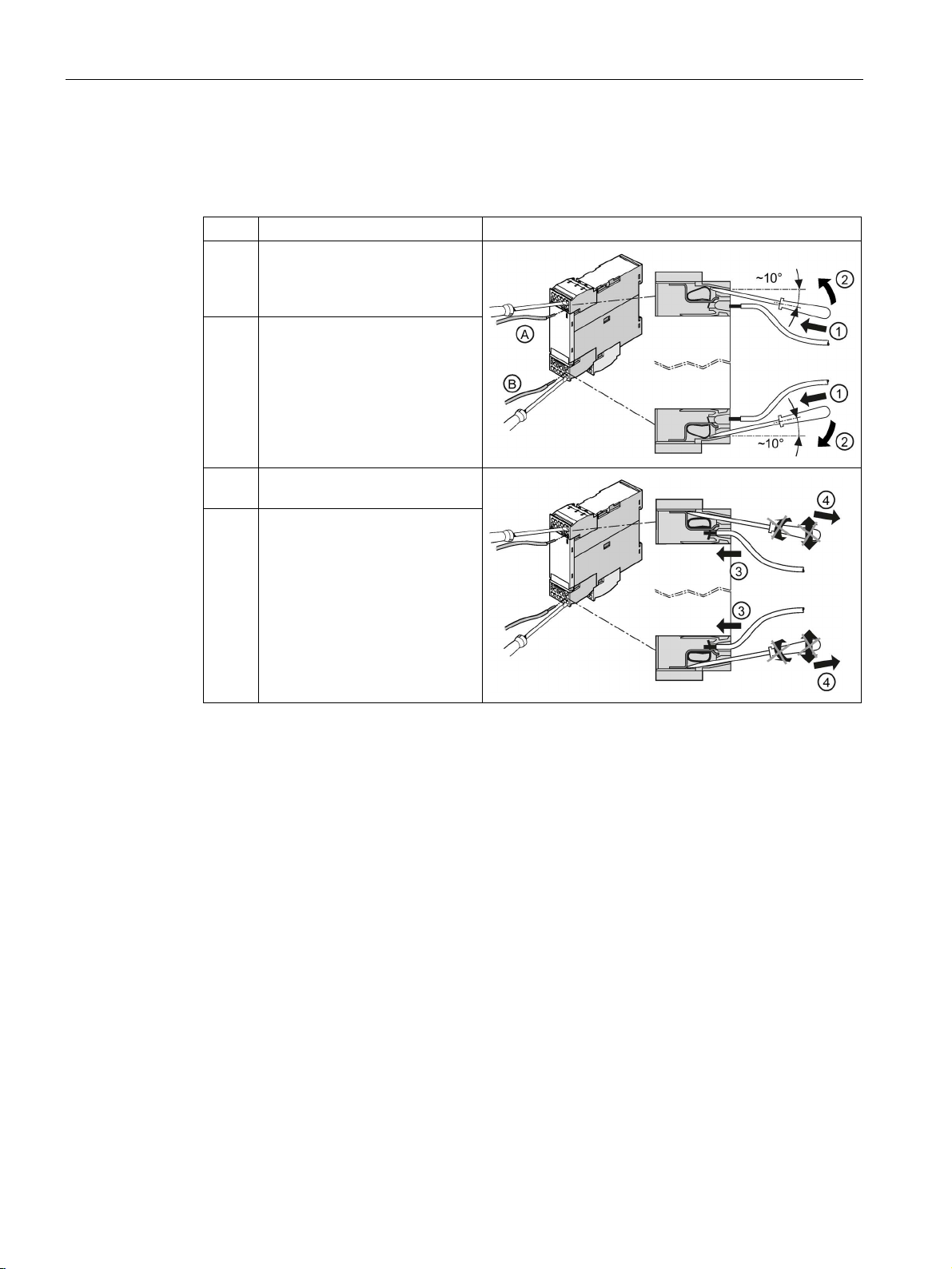
Step
Operating instruction
Figure
side.
connection slot.
3.3 Connection methods
Table 3- 4 Connecting the monitoring relay spring-loaded terminal
1 Insert the screwdriver into the
topmost (A) or bottommost (B)
operating slot on the right-hand
2 Press the screwdriver up (A) or
down (B), then push it into the
operating slot as far as it will go.
The screwdriver blade keeps the
spring-loaded terminal open
automatically.
3 Insert the conductor into the oval
4 Remove the screwdriver. The
terminal closes and the
conductor is now securely
clamped.
3UG4 / 3RR2 monitoring relays
26 Manual, 05/2016, NEB927043002000/RS-AC/004
Page 27
System overview
Connection cross-sections of the removable terminal blocks with a spring-loaded connection (3RR
and 3UG)
Removable terminal
AWG
2 x (24 to 16)
Connection cross-sections of the permanently connected terminal blocks with a spring-loaded
connection
Permanently connected terminal
Size S00
Size S0
3.3 Connection methods
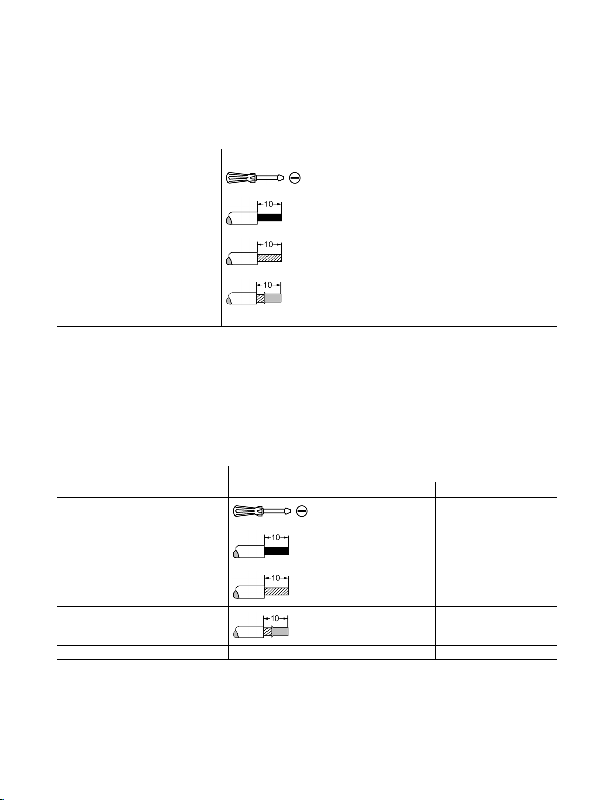
Table 3- 5 Removable terminal block with spring-loaded connections - monitoring relays
Tool
Solid and stranded
Finely stranded without end sleeve
Finely stranded with end sleeve
Ø 3.0 x 0.5 (3RA2908-1A)
2 x (0.25 to 1.5) mm²
2 x (0.25 to 1.5) mm²
2 x (0.25 to 1.5) mm²
The following table lists the permissible conductor cross-sections for the main conductor
terminals of the 3RR2 current monitoring relays for analog and digital setting (size S00 and
S0) with a spring-loaded connection.
Table 3- 6 Permanently connected terminal block with spring-loaded connection - main conductor terminals of
3RR2 current monitoring relays
Tool
Solid
Finely stranded without end sleeve
Finely stranded with end sleeve
AWG 1 x (20 to 12) 1 x (18 to 8)
3UG4 / 3RR2 monitoring relays
Manual, 05/2016, NEB927043002000/RS-AC/004
Ø3.0 x 0.5 (3RA2908-1A) Ø3.0 x 0.5 (3RA2908-1A)
1 x (0.5 to 4) mm² 1 x (1 to 10) mm²
1 x (0.5 to 2.5) mm² 1 x (1 to 6) mm²
1 x (0.5 to 2.5) mm² 1 x (1 to 6) mm²
27
Page 28
System overview
3.3.3
Device replacement by means of removable terminals
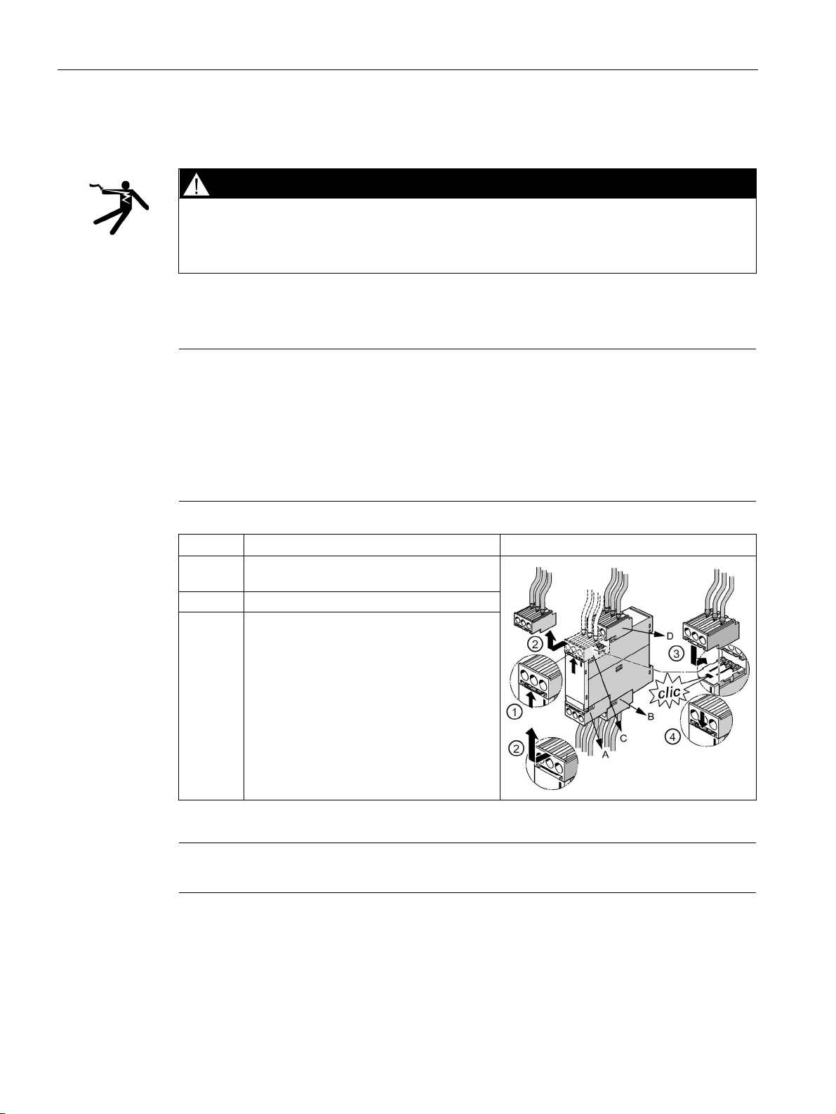
DANGER
Hazardous Voltage
Note
The terminals can only be dismantled in the
monitoring relay:
1.
2.
3.
4.
Step
Instructions
Figure
2
Remove the terminal to the front.
Note
The procedure is similar on devices with fewer connection terminals.
3.3 Connection methods
Will cause death or serious injury.
Turn off and lock out power before working on this equipment.
The removable terminals of 3UG4 monitoring relays facilitate device replacement when
necessary. The mechanical coding on the terminals prevents mix-ups.
following order due to their arrangement on the
Lower, front terminal (A)
Lower, rear terminal (B)
Upper, front terminal (C)
Upper, rear terminal (D)
1 Press the interlock in the direction of the
removable terminal.
3 / 4 Attach the new terminal and press the
terminal into the device until the interlock
audibly engages.
3UG4 / 3RR2 monitoring relays
28 Manual, 05/2016, NEB927043002000/RS-AC/004
Page 29

System overview
3.4
Mounting / removal
3.4.1
Mounting 3RR2 current monitoring relay
Mounting options
Minimum clearance
Mounting position
3.4 Mounting / removal
3RR2 current monitoring relays are matched to 3RT2 contactors and 3RF34 (size S0) solidstate contactors in terms of their electrical and mechanical features. As a result, direct
mounting can be achieved easily.
Alternatively, the devices can also be installed individually in the case of stand-alone
assembly or if a 3RU2 / 3RB3 overload relay is being used at the same time. The
accessories required for separate mounting are described in Chapter "Terminal support for
stand-alone assembly (Page 324)."
The following minimum clearances from grounded and live parts must be complied with
when installing the 3RR2 monitoring relay:
● At the side: 6 mm
● Forward (on front): 6 mm
It can be mounted in any position.
3UG4 / 3RR2 monitoring relays
Manual, 05/2016, NEB927043002000/RS-AC/004
29
Page 30
System overview
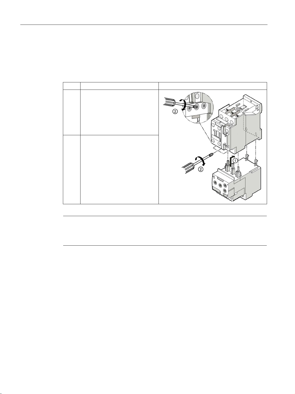
Direct mounting on 3RT2 contactor / 3RF34 (size S0) solid-state contactor
Step
Instructions
Figure
contactor.
Note
The connection cross
with screw
(Page
3.4 Mounting / removal
The diagram below shows an example mounting scenario based on mounting the
3RR21 analog setting current monitoring relay, size S0, on the 3RT2 contactor.
Table 3- 7 Mounting of 3RR2 current monitoring relay, screw-type connection system (size S0)
1 Push the current monitoring relay into
the contactor from below. Attach the
two hooks on the current monitoring
relay to the two openings on the rear
of the contactor. This pushes the
main current contacts into the
corresponding terminals on the
2 Tighten the screws on the contactor
with a Pozidriv size 2 (S00) or
Pozidriv size 3 (S0) screwdriver
(tightening torque 0.8 ... 1.2 Nm).
Check that the cable is clamped tight.
-sections of the removable and permanently connected terminal blocks
-type connections are described in the Chapter "Screw-type connection
21)".
3UG4 / 3RR2 monitoring relays
30 Manual, 05/2016, NEB927043002000/RS-AC/004
Page 31

System overview
Step
Instructions
Figure
tabs (zoom view) are inserted into the
Main conductor terminal on the contactor (a)
(S00):
Main conductor terminal on the contactor (a)
(S0):
Note
Adapter for direct mounting on 3RF34 solid-state contactor
For direct mounting on a 3RF34 solid
0QA88 adapter
is required, which is attached to the solid
"SIRIUS solid state contact
(
3.4 Mounting / removal
Table 3- 8 Mounting of 3RR2 current monitoring relay, spring-loaded connection system (size S0)
1 Insert the contacts (a) into the central
opening of the spring-loaded
terminals on the contactor (see
below, a), with the contacts flush to
the right. Make sure that the guide
designated slots on the contactor.
The current monitoring relay will sit
correctly flush with the contactor on
the left- and right-hand sides.
The figures below show the openings of the main conductor terminals on the contactor (S00
and S0) into which the contacts on the current monitoring relay have to be inserted.
http://support.automation.siemens.com/WW/view/en/44362244) operating instructions.
-state contactor, an additional 3RF3900-
-state contactor. Information is provided in the
ors / solid state reversing contactors"
3UG4 / 3RR2 monitoring relays
Manual, 05/2016, NEB927043002000/RS-AC/004
31
Page 32

System overview
Disassembly
Step
Instructions
Figure
conductor terminals.
Step
Instructions
Figure
contactor.
3.4 Mounting / removal
To disassemble the S00/S0/S2 assemblies from the DIN rail, press the contactor down and
pull it toward you.
Table 3- 9 Removing the 3RR2 current monitoring relay, screw-type connection system (size S0)
1 Undo the screws on the main
2 Pull the current monitoring relay
down and away from the contactor.
Table 3- 10 Removing the 3RR2 current monitoring relay, spring-loaded connection system (size
S00)
1 Position the screwdriver on the
current monitoring relay as shown
in the figure. Carefully dislodge the
current monitoring relay from the
2 Pull the current monitoring relay
toward you and away from the
contactor.
3UG4 / 3RR2 monitoring relays
32 Manual, 05/2016, NEB927043002000/RS-AC/004
Page 33

System overview
Step
Instructions
Figure
terminals.
3
screwdriver
5
Swing the contactor
Separately mounted
Note
The accessories required for separate mounting are described in
support for stand
3.4 Mounting / removal
Table 3- 11 Removing the 3RR2 current monitoring relay (size S2)
1 Undo the screws on
the main conductor
2 Pull the current
monitoring relay down
and away from the
contactor
Push the release slide
4
down with a
upwards to remove it
-alone assembly (Page 324)".
3UG4 / 3RR2 monitoring relays
Manual, 05/2016, NEB927043002000/RS-AC/004
the Chapter "Terminal
33
Page 34

System overview
3.4.2
Mounting the 3UG4 monitoring relay
Mounting position
Screw mounting
Step
Operating instruction
Image
secure the device by screwing suitable screws through the
Standard-rail mounting
Step
Operating instruction
Image
3.4 Mounting / removal
It can be mounted in any position.
The illustration below shows how to screw-mount the 3UG4 monitoring relay.
Table 3- 12 Mounting the monitoring relay (screw mounting)
1 Slide the push-in lugs into the openings on the monitoring
relay at the top and bottom, and use the screwdriver to
holes in the push-in lugs.
The illustration below shows how to mount the 3UG4 monitoring relay onto a standard rail.
Table 3- 13 Mounting the monitoring relay (mounting on and removing from standard rail)
1 Position the device on the top edge of the mounting rail
and press it down until it snaps onto the bottom edge of
the rail.
To remove the device, press it down, pushing against the
mounting springs, and swivel the device to remove it.
3UG4 / 3RR2 monitoring relays
34 Manual, 05/2016, NEB927043002000/RS-AC/004
Page 35

System overview
3.4.3
Installing the 3UG458. monitoring relay.
Rail mounting
Step
Instructions
Figure
DIN rail and press down until it snaps onto
Step
Instructions
Figure
spring.
3.4 Mounting / removal
The figure below shows how to install the 3UG458. insulation monitoring relay on a standard
rail.
Table 3- 14 Installing the 3UG458. insulation monitoring relay (mounting onto standard rail)
1 / 2 Position the device on the top edge of the
the bottom edge of the DIN rail.
Table 3- 15 Removing the 3UG458. insulation monitoring relay. (Removing from standard rail)
1 / 2 To remove, apply the screwdriver to the
device and push it up with a twisting
motion against the tension of the fixing
3 Swing the device upwards to remove it.
3UG4 / 3RR2 monitoring relays
Manual, 05/2016, NEB927043002000/RS-AC/004
35
Page 36

System overview
3.5
Overview of the functions
3.5.1
3RR2 current monitoring relays
Function
Current monitoring relay
3RR21
3RR22
Current monitoring
Monitoring for undercurrent
2p
3p
Monitoring for overcurrent
2p
3p
Apparent current monitoring
✓
✓
Range monitoring
2p
3p
Monitoring for phase sequence
— ✓ Internal ground-fault detection (fault current monitoring)
—
✓
Blocking current monitoring
—
✓
Supply voltage
Self-powered, without auxiliary voltage
—
—
Externally powered, with auxiliary voltage
✓
✓
✓
2p: Monitoring is 2
3p: Monitoring is 3
— : Function not available
3.5 Overview of the functions
Table 3- 16 Functions of the 3RR21 / 3RR22 current monitoring relays for analog and digital setting
Active current monitoring — ✓
Monitoring for phase failure, wire break 2p 3p
: Function available
-phase
-phase
3UG4 / 3RR2 monitoring relays
36 Manual, 05/2016, NEB927043002000/RS-AC/004
Page 37

System overview
3.5.2
3UG45 / 3UG46 monitoring relays
Function
Monitoring relays
3UG45
3UG46
01
11
12
13 8 14
15
16
17
18
31
32
33
21
22
41
25
51
Line monitoring and voltage monitoring
Monitoring for phase
sequence
— ✓ ✓ ✓ — ✓ ✓ ✓ ✓ ✓ — — — — — — —
—
failure
asymmetry
undervoltage
overvoltage
failure
sequence
Power factor monitoring and current monitoring
undercurrent
monitoring
monitoring
Power factor monitoring
— — — — — — — — — — — — — — — ✓ —
—
Fault current monitoring/insulation monitoring
current/ground fault
Insulation monitoring
— — — — ✓ — — — — — — — — — — — —
—
Filling level monitoring
overshoot
undershoot
3.5 Overview of the functions
Table 3- 17 Functions of the 3UG45/3UG46 monitoring relays for analog and digital setting
Monitoring for phase
Monitoring for
Monitoring for
Monitoring for
Monitoring for N
conductor
Automatic direction of
rotation correction in the
case of incorrect phase
Monitoring for
Monitoring for
overcurrent
Active current
Apparent current
— ○1) ✓ ✓ — ✓ ✓ ✓ ✓ ✓ — — — — — — — —
— — 10 % 20 % — ✓ ○2) ○2) ✓ ✓ — — — — — — — —
— — — 3p — 3p 3p 3p 3p 3p 1p 1p 1p — — — — —
— — — — — — 3p 3p 3p 3p 1p 1p 1p — — — — —
— — — — — — — ✓ — ✓ — — — — — — — —
— — — — — — — — ✓ ✓ — — — — — — — —
— — — — — — — — — — — — — 1p 1p 1p — —
— — — — — — — — — — — — — 1p 1p 1p — —
— — — — — — — — — — — — — — — ✓ — —
— — — — — — — — — — — — — ✓ ✓ — — —
Monitoring for fault
Monitoring for filling level
overshoot / resistance
Monitoring for filling level
undershoot / resistance
3UG4 / 3RR2 monitoring relays
Manual, 05/2016, NEB927043002000/RS-AC/004
— — — — — — — — — — — — — — — — ✓ —
✓ — — — — — — — — — — — — — — — — —
✓ — — — — — — — — — — — — — — — — —
37
Page 38

System overview
Function
Monitoring relays
3UG45
3UG46
01
11
12
13 8 14
15
16
17
18
31
32
33
21
22
41
25
51
Speed monitoring
undershoot
Rated control supply voltage
auxiliary voltage
auxiliary voltage
✓
1p: Monitoring is 1
3p: Monitoring is 3
—
○: Function available with limitations
1)
2)
By monitoring the voltage thresholds.
True root mean square measurement (tRMS) / use with frequency converters:
3.5 Overview of the functions
Monitoring for speed
overshoot
Monitoring for speed
Self-powered, without
Externally powered, with
: Function available
-phase
-phase
: Function not available
Detection causes problems with regenerative power recovery.
— — — — — — — — — — — — — — — — — ✓
— — — — — — — — — — — — — — — — — ✓
— ✓ ✓ ✓ — ✓ ✓ ✓ ✓ ✓ — — ✓ — — ✓ — —
✓ — — — ✓ — — — — — ✓ ✓ — ✓ ✓ — ✓ ✓
The monitoring relays work with an electronic measuring method which calculates the actual
(effective) value of a measured value (tRMS), regardless of whether the measured variable's
waveform is purely sinusoidal or distorted.
The measured signal must only meet the following requirements:
● Periodic waveform (sinusoidal) within the specified frequency range
● Continuous zero crossings
As long as the line on the primary or the secondary side in the environment of a frequency
converter fulfills these requirements, the monitoring relays can also be operated upstream or
downstream of frequency converters. The required line quality can be ensured by using line
filters/sine-wave filters where applicable. Of course, the suitability of the relevant monitoring
relay for the monitored line frequencies must also be considered.
3UG4 / 3RR2 monitoring relays
38 Manual, 05/2016, NEB927043002000/RS-AC/004
Page 39

System overview
3.6
Menu-based operation
Operator controls
3.6 Menu-based operation
The digitally adjustable monitoring relays have three keys for navigating on the menu levels:
● SET key
● 2 arrow keys
Navigation through the menu system of the monitoring relays is explained below in a
schematic diagram.
Depending on the device version and as long as no faults have occurred, one or
different measuring values
of a fault, the display indicates the type of fault
repeatedly pressing the SET key briefly, it is possible to set the desired type of monitoring
(overshoot, undershoot, or range monitoring) and parameterize the lower and/or upper
threshold
key for at least 2.5 s, in a further step, the basic device parameters
behavior of the output relays, the reset response in the event of a fault, and/or the tripping
delay times can be set.
for navigating to the menu levels and for switching between the menu levels
for setting parameters
more
① can be displayed with the help of the arrow keys. In the event
③ by means of flashing symbols. By
② in accordance with the device-specific setting ranges. After pressing the SET
④, such as the switching
3UG4 / 3RR2 monitoring relays
Manual, 05/2016, NEB927043002000/RS-AC/004
39
Page 40

System overview
Menu-based operation
①
RUN - OK
②
RUN - VALUE
Settings of the monitored thresholds, see below
③
RUN - ERROR
Status display in the event of a fault
indicates the type of error.
④
SET
Settings for basic device parameters, see below
3.6 Menu-based operation
• Measured value1 /
Measured value2 / ...
If a threshold is overshot or undershot, the outputs of the
• Error1 /Error2 / ...
3UG4 / 3RR2 monitoring relays
40 Manual, 05/2016, NEB927043002000/RS-AC/004
Status display in the correct range, see below
monitoring relays switch over after the set delay time. The display
Error detected
Page 41

System overview
Menu levels "RUN" and "SET"
3.6 Menu-based operation
The RUN menu shows the up-to-date current measured value ①. You can use the arrow
keys
In this case, the display automatically switches between the name of the measured value
and the actual measured value.
to change between the individual measuring values on devices with multiple outputs.
② represents the selected type of monitoring (overshoot, undershoot, or range monitoring).
An arrow symbol indicates whether the measuring value is within, above or below the set
thresholds.
Next to this, one or two symbols
semiconductor output) and the switching status of the outputs.
③ represent the type (changeover contact or
3UG4 / 3RR2 monitoring relays
Manual, 05/2016, NEB927043002000/RS-AC/004
41
Page 42

System overview
3.6 Menu-based operation
Navigation in the menu
There are basically two ways of navigating on both menu levels:
● Brief pressing the SET key
(≤ 0.5 s)
You can jump from one parameter to the next within one menu level by briefly pressing
the SET key
Entry Display at the RUN menu level Display at the SET menu level
1. Current measuring value (MeasValue1 /
MeasValue2 / ...) or error symbol (Error1 / Error2 /
Error3 / ...), switching contact symbols and
monitoring methods for diagnostics
2. Threshold1 Parameter2
3. Threshold2 Parameter3
4. Threshold3 ...
5. ...
Note
. The order is not variable.
Parameter1
The setting options a device actually offers depends on the type and can be looked up in
the relevant chapters on operation in this manual.
You can find full details of menu-based operation for the individual devices in Appendix D
"Menu-based operation" (Page 389).
● Pressing and holding the SET key (> 2.5 s)
By pressing and holding the SET key
, the menu changes from RUN to SET and vice
versa.
– RUN → SET
Menu level change can be started from any display. While the SET key is pressed,
appears on the display.
After a successful change, you always arrive at the first menu item (parameter1) of the
"SET" menu level.
In the event of an error, changing to the "SET" menu level is only possible from "RUNVALUE"
②. If an error is indicated, the SET key must be pressed first briefly (< 0.5 s).
– SET → RUN
You can switch menus from any of the menu commands. While the SET key
pressed,
appears on the display.
After a successful change, you arrive at current measuring value (measuringvalue1) or
the current error of the RUN menu level.
is
3UG4 / 3R R2 monitoring relays
42 Manual, 05/2016, NEB927043002000/RS-AC/004
Page 43

System overview
3.6 Menu-based operation
Note
Aborting the menu switchover
The switchover process will be interrupted if the SET key
is released while or
is displayed. The menu will revert to the menu command you were working with when the
switch was initiated.
Note
Reset in the event of an error
To reset the device, it is necessary to press both arrow keys
simultaneously for more than
2.5 s after removal of the cause of error and with Hand-RESET active. While the keys are
pressed,
appears on the display.
The possible settings for resetting the devices via the "Reset response" parameter can be
found in the "Operation" chapters of the relevant monitoring relays.
Note
3UG4625 residual current monitoring relays automatically return to showing the actual
measured value 30 seconds after the last limit value change.
Note
Quitting the SET menu level will trigger an internal reset in 3UG4621/3UG4622/3UG4625
and 3UG4641 device variants and restart the startup delay.
3UG4 / 3RR2 monitoring relays
Manual, 05/2016, NEB927043002000/RS-AC/004
43
Page 44

System overview
3.6 Menu-based operation
3UG4 / 3RR2 monitoring relays
44 Manual, 05/2016, NEB927043002000/RS-AC/004
Page 45

4
4.1
Product description
Overview
SIRIUS 3RR2 current monitoring relays are suitable for current monitoring of motors or other
loads. They are capable of two-phase or three-phase monitoring of the rms value of AC
currents, checking that the values do not overshoot or undershoot set thresholds.
SIRIUS 3RR2 current monitoring relays are available in the following variants:
● Basic version (3RR21): with analog setting using rotary buttons, two-phase monitoring
and CO contact.
● Basic version (3RR22): digital setting via a display, 3-phase monitoring, CO contact, and
semiconductor output; also monitors phase sequence, phase failure, ground fault and
blocking current
● Version for IO-Link (3RR24): same as standard version, but additionally with IO-Link
interface for direct interfacing to a PLC for remote parameterization, remote diagnostics,
cyclic transfer of measured values, support of the parameter server functionality of IOLink (with master as from specification V1.1), with integrated runtime and switching cycle
counter
You can find further information in the Manual "3UG48/3RR24 Monitoring Relays for IOLink".
Whereas apparent current monitoring is primarily used in the rated torque range or for
overload, active current monitoring can be used to observe and evaluate the degree of
loading across a motor's entire torque range.
Apparent current monitoring and active current monitoring are described in more detail in the
Chapter "Parameters (Page 363)".
3UG4 / 3RR2 monitoring relays
Manual, 05/2016, NEB927043002000/RS-AC/004
45
Page 46

3RR2 current monitoring relays
System integration
①
Complete device functionality possible
②
Device functionality only possible with limitations:
Note
The monitoring functions of the 2
output relay(s), i.e. a fault in one monitored phase (e.g. current violation
the output relay(s).
Accessories
4.1 Product description
3RR2 current monitoring relays are available in three sizes, S00, S0 and S2. 3RR2 current
monitoring relays are matched to 3RT2 contactors and 3RF34 (size S0) solid-state
contactors in terms of their electrical and mechanical features. They can be integrated in the
feeder by means of direct mounting. This eliminates the need for the main circuit to be wired
separately and no additional transformers are required.
For a stand-alone assembly or if an overload relay is being used at the same time, terminal
supports for stand-alone assembly are available for separate DIN rail mounting.
3RR2 current monitoring relays were conceived for monitoring 3-phase systems.
Depending on the device version used, monitoring of 1- or 2-phase AC systems is possible
with the following wiring variants:
• Residual current monitoring not possible (→ switch off)
• Phase sequence monitoring not possible (→ switch off)
• Active current monitoring not possible (→ switch off)
phases (3RR21) or the 3 phases (3RR22) are ORed to the
The accessories have been tailored to the current monitoring relays; they can be mounted
easily and without the need for tools. The accessories are described in the Chapter
"Accessories for 3RR2 current monitoring relays (Page 323)".
3UG4 / 3RR2 monitoring relays
46 Manual, 05/2016, NEB927043002000/RS-AC/004
L1) already affects
Page 47

3RR2 current monitoring relays
4.2
Application areas
Function
Application
4.2 Application areas
The 3RR2 current monitoring relays are used, for example, in the following applications:
● Monitoring for current overshoot and current undershoot
● Monitoring for cable breaks
● Monitoring for no-load operation and load shedding (as might be the case, for example, in
the event of a torn V belt)
● Underload monitoring in the lower performance range (if a pump was running in no-load
operation, for example)
● Monitoring for overload (as might affect pumps with a soiled filter system, for example)
● Monitoring the performance of electrical loads such as heaters
● Monitoring for incorrect phase sequences on mobile equipment such as compressors or
cranes
● Monitoring for high-impedance faults to ground (caused by damaged insulation or
moisture, for example)
Table 4- 1 Application areas of the 3RR2 current monitoring relays
• Undercurrent
• Overcurrent
• Apparent current
• Active current (3RR22 only)
• Phase failure / wire break
• Phase sequence (3RR22 only)
• Internal ground fault detection (fault
current) (3RR22 only)
• Block current (3RR22 only)
• Emergency lighting
• Heating systems (electroplating plants, plastic injection
machines, paintshops)
• Lamps (tunnels, OR lighting, traffic lights, signal
systems, UV lamps, infrared radiators, laser lamps)
• Fan
• Pumps
• Sawing system
• Conveyor belt
• Surface grinding machine
• Breaking mill
• Milling machine
• Car wash
• Lifting platform
• Screw conveyor
• Crane
• Turning machine
• Woodworking
• Grain mills
• Steel industry
3UG4 / 3RR2 monitoring relays
Manual, 05/2016, NEB927043002000/RS-AC/004
47
Page 48

3RR2 current monitoring relays
4.3
Performance features of current monitoring relays
Functions/Parameters
Current monitoring relays with analog setting
3RR2141-.A.30
3RR2142-.A.30
3RR2143-.A.30
Rated current
1.6 to 16 A
4 to 40 A
8 to 80 A
Frequency range
50/60 Hz AC
50/60 Hz AC
50/60 Hz AC
overshoots and/or undershoots
Contacts
1 CO contact
1 CO contact
1 CO contact
Functions/Parameters
Current monitoring relays with digital setting
3RR2241-.F.30
3RR2242-.F.30
3RR2243-.F.30
Rated current
1.6 to 16 A
4 to 40 A
8 to 80 A
Frequency range
20 to 400 Hz AC
20 to 400 Hz AC
20 to 400 Hz AC
overshoots and/or undershoots
1 semiconductor output
1 semiconductor output
1 semiconductor output
4.3 Performance features of current monitoring relays
Table 4- 2 Performance features of 3RR2 current monitoring relays with analog setting
Supply voltage Us
Monitoring for current
Table 4- 3 Performance features of 3RR2 current monitoring relays with digital setting
Supply voltage Us
Monitoring for current
Contacts 1 CO contact/
• -.AA30: 24 V AC/DC
• -.AW30: 24 to 240 V AC/DC
2-phase 2-phase 2-phase
• -.FA30: 24 V AC/DC
• -.FW30: 24 to 240 V AC/DC
3-phase 3-phase 3-phase
1 CO contact/
1 CO contact/
3UG4 / 3RR2 monitoring relays
48 Manual, 05/2016, NEB927043002000/RS-AC/004
Page 49

3RR2 current monitoring relays
4.3.1
General data
Feature
Benefit
3RR21 Basic,
analog setting
3RR22 Standard,
digital setting
4.3 Performance features of current monitoring relays
Table 4- 4 General data for 3RR2 current monitoring relays
Sizes
Current range
• The devices are matched to the dimensions, connections
and technical features of the other devices in the SIRIUS
modular system.
• The devices permit mounting of slim-line and compact load
feeders in widths of 45 mm (S00 and S0) or 55 mm (S2).
• The devices make configuration easier.
• The devices are matched to the other devices in the
SIRIUS modular system
• Just 1 option per size with a wide setting range makes
configuration easy.
S00, S0, S2 S00, S0, S2
S00: 1.6 to 16 A
S0: 4.0 to 40 A
S2: 8.0 to 80 A
S00: 1.6 to 16 A
S0: 4.0 to 40 A
S2: 8.0 to 80 A
You can find further technical information on 3RR24 in the Manual "3UG48/3RR24
monitoring relays for IO-Link
(http://support.automation.siemens.com/WW/view/en/54375430)" on the internet.
3UG4 / 3RR2 monitoring relays
Manual, 05/2016, NEB927043002000/RS-AC/004
49
Page 50

3RR2 current monitoring relays
4.3.2
Properties
Feature
Benefit
3RR21 Basic,
analog setting
3RR22 Standard,
digital setting
ing and reconnecting the supply voltage
4.3 Performance features of current monitoring relays
Table 4- 5 Equipment of 3RR2 current monitoring relays
Reset function
ON-delay time
Tripping delay time
Operating and
indicating elements
Integrated contacts
• Enables manual or automatic resetting of the
monitoring relay
• Resetting directly on the device or by
disconnect
(remote reset)
• Enables motor starting without evaluation of the
starting current
• Can be used to monitor motors with lengthy
startup
• Prevents frequent warnings and disconnection in
response to currents in the vicinity of the
thresholds
• Permits brief violations of thresholds during
operation
• For setting thresholds and delay times
• For selectable functions
• For fast and selective diagnostics
• Display for permanent indication of measured
values
• Allow the system or process to be shut down in
the event of an irregularity
• Can be used to output signals
✓ ✓
0 s to 60 s 0 to 99 s
0 s to 30 s 0 s to 30 s
LEDs and rotary
buttons
1 CO contact 1 CO contact
Display and buttons
1 semiconductor
output
3UG4 / 3RR2 monitoring relays
50 Manual, 05/2016, NEB927043002000/RS-AC/004
Page 51

3RR2 current monitoring relays
4.3.3
Configuration of load feeders
Feature
Benefit
3RR21 Basic,
analog setting
3RR22 Standard,
digital setting
protector)
Provides optimum protection of the loads
4.3 Performance features of current monitoring relays
Table 4- 6 Load feeders with 3RR2 current monitoring relays
Short-circuit-proof up to 100 kA at
690 V
(in conjunction with the appropriate
fuses or the appropriate motor starter
Electrical and mechanical matching to
3RT2 contactors
Spring-loaded connection system for
main circuit (option) and auxiliary
circuit (option)
•
and operating personnel in the event of
short circuits due to insulation faults or
faulty switching operations
• Simplifies configuration
• Reduces connection outlay and costs
• Enables stand-alone assembly as well
as space-saving direct mounting
• Enables fast connections
• Ensures that connections are vibration-
resistant
• Enables maintenance-free connections
✓ ✓
✓ ✓
✓ ✓
3UG4 / 3RR2 monitoring relays
Manual, 05/2016, NEB927043002000/RS-AC/004
51
Page 52

3RR2 current monitoring relays
4.3.4
Combinations with 3RT20 contactor
Monitoring relay type
Current range
3RT20 1 S00 contactors
3/4/5.5/7.5 kW
3RT20 2 S0 contactors
5.5/7.5/11/15/18.5 kW
3RT20 3 S2 contactors
18.5/22/30/37 kW
3RR2141
1.6 to 16 A ✓ X
X
3RR2241
1.6 to 16 A ✓ X
X
3RR2142
4.0 to 40 A X ✓
X
3RR2242
4.0 to 40 A X ✓
X
3RR2143
8.0 to 80 A X X
✓
3RR2243
8.0 to 80 A X X
✓
X = with stand-alone assembly support
4.3 Performance features of current monitoring relays
You can find further technical information on 3RR24 in the Manual "3UG48/3RR24
monitoring relays for IO-Link
(http://support.automation.siemens.com/WW/view/en/54375430)" on the internet.
3UG4 / 3RR2 monitoring relays
52 Manual, 05/2016, NEB927043002000/RS-AC/004
Page 53

3RR2 current monitoring relays
4.4
3RR21 current monitoring relays
4.4.1
Operator controls and connection terminals
Front view / terminal labeling (basic version)
Front view
Description
Position digits
①
②
③
parameter (manual/autoreset):
⑤
type or the spring-loaded connection system.
⑦
⑧
⑨
voltage and "Fault" (red) for switching state
Terminal labels
B1
Supply voltage ∼ / +
B2
Supply voltage ∼ / -
contact
contact
2/T1, 4/T2, 6/T3
Main circuit terminals
14 / 22
Feed-through contactor auxiliary switch (S00)
A2
Feed-through contactor coil terminal (S00)
4.4 3RR21 current monitoring relays
Connection for contactor mounting or for stand-alone
assembly
Rotary button for setting the threshold for overshoot "I▲"
Rotary button for setting the threshold for undershoot "I▼"
④
⑥
Sliding switch "Memory" for selecting the reset response
Control circuit terminal (removable):
The control circuit can be connected using either the
screw-type or the spring-loaded connection system.
Main circuit terminal (permanently connected) :
The main circuit can be connected using either the screw-
Label (below which there is a DATAMatrix code)
⑩
⑪
32 Output relay K1 changeover contact NC
31 Output relay K1 changeover contact root
34 Output relay K1 changeover contact NO
Device article number
Rotary button for startup delay time "onDel (s)"
Rotary button for tripping delay time "Del (s)"
Status display via "Ready" LEDs (green) for auxiliary
You can find additional information on the connection terminals and the permissible
conductor cross-sections in the Chapter "Connection methods (Page 21)".
You can find information on connecting in the Chapter "Circuit diagrams (Page 59)".
3UG4 / 3RR2 monitoring relays
Manual, 05/2016, NEB927043002000/RS-AC/004
53
Page 54

3RR2 current monitoring relays
4.4.2
Function
General functionality
overshoot
undershoot
range monitoring
Cable break detected
①
Cable break detected
②
No cable break
③
- S2: 6.0 A to 8.0 A
4.4 3RR21 current monitoring relays
Depending on the setting, the current monitoring relays monitor an AC load current that flows
through terminals 1/L1 - 2/T1 and 3/L2 - 4/T2 of the device for
(I▼) or in
Depending on their design, the current monitoring relays are powered with a 24 V AC/DC or
24 to 240 V AC/DC supply voltage through terminals B1/B2.
With two-phase apparent current monitoring, one changeover output, and analog
adjustment, the 3RR214.-.A.30 (basic-version) current monitoring relays provide a high level
of monitoring reliability particularly in the rated and overload ranges.
The switching states of the output relay are given below in the section entitled "Function
diagrams."
(I▲ and I▼ ≠ OFF).
(I▲) or
Hysteresis cable break:
- S00: 1.2 A to 1.6 A
- S0: 3.0 A to 4.0 A
Image 4-1 Diagram of cable break
If a cable break (zero current in branch circuit 1/L1 - 2/T1 or 3/L2 - 4/T2) is detected (time
①), all running delay times are aborted, the red FAULT LED flashes rapidly and the CO
contact immediately changes its switching state.
When a defined current flow returns to both branch circuits (1/L1 - 2/T1, 3/L2 - 4/T2) (time
②), the CO contact responds according to the defined settings.
If Memory = I, the tripping state is saved.
If the unmonitored phase 5/L3 - 6/T3 fails, this can be detected if a motor is connected by an
increase in current in both phases 1/L1 - 2/T1 and 3/L2 - 4/T2.
3UG4 / 3RR2 monitoring relays
54 Manual, 05/2016, NEB927043002000/RS-AC/004
Page 55

3RR2 current monitoring relays
Function diagrams
Memory = O:
Memory = I:
4.4 3RR21 current monitoring relays
I▲
I▼ = Off
I▲ = Off
I▼
I▲
I▼
3UG4 / 3RR2 monitoring relays
Manual, 05/2016, NEB927043002000/RS-AC/004
55
Page 56

3RR2 current monitoring relays
4.4.3
Operation
Parameters
Parameters
Control
element 5)
Setting range
Increment
Factory
setting
Minimum value
Maximum value
ON-delay time (onDel)
9
0 s
60 s
Continuous
0 s
Tripping delay time (Del)
10
0 s
30 s
Continuous
0 s
8 A or OFF3)
80 A3)
reset
Hysteresis
4.4 3RR21 current monitoring relays
The following parameters can be set on the relevant rotary button using a screwdriver:
Table 4- 7 Parameter information, 3RR21 current monitoring relays with analog setting
Threshold for current overshoot
(I▲)
Threshold for current undershoot
(I▼)
2 1.6 A or OFF
4 A or OFF2)
8 A or OFF
3 1.6 A or OFF
4 A or OFF
1)
3)
1)
2)
16 A
40 A
80 A3)
16 A
40 A
1)
2)
Continuous 8 A
20 A
1)
2)
40 A3)
1)
2)
Continuous Disabled
Reset response (Memory) 4 0 = automatic rest 1 = manual reset 4) -- Automatic
1)
current monitoring relay 3RR2141-.A.30
2)
current monitoring relay 3RR2142-.A.30
3)
current monitoring relay 3RR2143-.A.30
4)
a stored fault condition can be reset by briefly switching to Memory = 0 or by switching off
the supply voltage.
5)
The position digits refer to the front view in the Chapter "Operator controls and connection
terminals (Page 53)."
The hysteresis is set to a fixed value of 6.25% of the set threshold.
3UG4 / 3RR2 monitoring relays
56 Manual, 05/2016, NEB927043002000/RS-AC/004
Page 57

3RR2 current monitoring relays
Changes to settings of threshold for current overshoot (I▲) and threshold for current undershoot (I▼)
Note
Deactivating monitoring
If both threshold values are deactivated (OFF),
•
•
The following parameters continue to be monitored:
•
Required tools
4.4 3RR21 current monitoring relays
the following will no longer be monitored:
Current overshoot
Current undershoot
Phase failure
The parameters are described in the Chapter "Parameters (Page 363)".
The same screwdriver can be used to set the parameters as for mounting the current
monitoring relays.
3UG4 / 3RR2 monitoring relays
Manual, 05/2016, NEB927043002000/RS-AC/004
57
Page 58

3RR2 current monitoring relays
4.4.4
Diagnostics
Status display
Display
Meaning
FAULT off
Measured value is within range limits
FAULT steady on
Device has tripped
FAULT flashes at 1 Hz
Delay time is running
READY off
Voltage is not applied at B1 - B2
4.4 3RR21 current monitoring relays
On the current monitoring relay with analog setting, two status LEDs indicate the operating
state:
● FAULT (red)
● READY (green)
FAULT flashes at 4 Hz Cable break/phase failure detected
READY on Voltage is applied at B1 - B2
You can find more information about the LED display response in the Chapter "Function
(Page 54)."
3UG4 / 3RR2 monitoring relays
58 Manual, 05/2016, NEB927043002000/RS-AC/004
Page 59

3RR2 current monitoring relays
4.4.5
Circuit diagrams
Internal circuit diagrams 3RR21
3RR2141-1A.30 current monitoring relay
3RR2141-2A.30, 3RR2142-.A.30, 3RR2143-.A.30 current monitoring relays
4.4 3RR21 current monitoring relays
Image 4-2 1 CO contact, 2-phase
Image 4-3 1 CO contact, 2-phase
3UG4 / 3RR2 monitoring relays
Manual, 05/2016, NEB927043002000/RS-AC/004
59
Page 60

3RR2 current monitoring relays
4.4.6
Technical data
General technical specifications
3RR2141-.....
3RR2142-.....
3RR2143-.....
product brand name
SIRIUS
Product designation
multi-phase current monitoring
Design of the product
multi-phase current monitoring
Size of the contactor
can be
combined company-specific
Protection class IP
Insulation voltage
for
overvoltage category III
according to IEC 60664
with
degree of pollution 3
rated
value
Installation altitude
at a height
over sea level
maximum
Ambient temperature
Electromagnetic compatibility
IEC 60947-1 / IEC 61000-6-2 / IEC 61000-6-4
EMC immunity to interference
according to IEC 60947-1
EMC emitted interference
according to IEC 60947-1
Resistance against shock
15g / 11 ms
10g / 11 ms
Resistance against vibration
10 ... 55 Hz / 0.35 mm
Impulse voltage resistance
rated value
Operating apparent output
rated
value
Rating Rated value
W
2.5
4.4 3RR21 current monitoring relays
• on the front
• of the terminal
• during storage
• during operating
S00 S0 S2
IP20
IP20 IP00
V 690
2 000
m
-40 … +80
°C
-25 … +60
ambience A (industrial sector)
ambience A (industrial sector)
3UG4 / 3RR2 monitoring relays
60 Manual, 05/2016, NEB927043002000/RS-AC/004
kV 6
V·A 4
Page 61

3RR2 current monitoring relays
3RR2141-.....
3RR2142-.....
3RR2143-.....
Reference code
Mechanical operating cycles as
operating time
typical
Electrical operating cycles as
operating time
at AC-15
at
230 V typical
Adjustable response delay time
Standby time
for restart after
fault
Phase number
3 Number of monitored phases
Product function
4.4 3RR21 current monitoring relays
K
• according to DIN 40719
extended according to
IEC 204-2 according to
IEC 750
• according to DIN EN
61346-2
• when starting
• with lower or upper limit
violation
K
10 000 000
100 000
0 … 60
s
s
0 … 30
s 0.3
2
• overcurrent monitoring
• undercurrent monitoring
• overcurrent and undercurrent
monitoring
• apparent current monitoring
• active current monitoring
• undercurrent recognition of
3 phases
• phase sequence recognition
• can be activated or
deactivated phase sequence
recognition
• self-reset
• reset external
• manual RESET
Yes
Yes
Yes
Yes
No
No
No
No
Yes
No
Yes
3UG4 / 3RR2 monitoring relays
Manual, 05/2016, NEB927043002000/RS-AC/004
61
Page 62

3RR2 current monitoring relays
3RR2141-.....
3RR2142-.....
3RR2143-.....
Adjustable response current
Factor
as multiple of the
current monitoring upper limit
Response value residual
current detection
at 50/60 Hz
typical
Type of current for monitoring
AC
Measurable current
Adjustable switching hysteresis
for measured current value
Relative switching hysteresis
for
measured current value
Response time maximum
s
0.3
Relative repeat accuracy
%
2
Relative metering precision
with
regard to measuring range
limit
Temperature drift per °C
%/°C
0.1
Current-carrying capacity
1)
Class 10 = 80 A
Class 30 = 50 A
4.4 3RR21 current monitoring relays
• 1
• 2
• for the adjustable value of
a blocking current
• for AC
A
A
A —
A
A — —
1.6 … 16 4 … 40 8 … 80
1.6 … 16 4 … 40 8 … 80
— —
1.6 … 16 4 … 40 8 … 80
• for permanent overcurrent
maximum permissible
• for overcurrent duration
< 1 s maximum permissible
Class 20 = 60 A
6.25
%
% 10
A
16 40 801)
A
320 800 1 600
62 Manual, 05/2016, NEB927043002000/RS-AC/004
3UG4 / 3RR2 monitoring relays
Page 63

3RR2 current monitoring relays
Connections 3RR2141 (size S00)
3RR2141-1....
3RR2141-2....
Design of the electrical connection
Product function
Type of the connectable conductor crosssection
Tightening torque
Verification of suitability
CE / UL / CSA
4.4 3RR21 current monitoring relays
• for main current circuit
• for auxiliary and control current circuit
• removable terminal for main circuit
• removable terminal for auxiliary and
control circuit
• for main contacts
– solid
– stranded
– finely stranded
– with conductor end processing
– without conductor final cutting
• for AWG conductors for main contacts
• for auxiliary contacts
– solid
– finely stranded
– with conductor end processing
– without conductor final cutting
• for AWG conductors for auxiliary
contacts
screw-type terminals spring-loaded terminals
screw-type terminals spring-loaded terminals
No
Yes
2x (0.5 ... 1.5 mm²),
2x (0.75 ... 2.5 mm²),
2x (1 ... 4 mm²)
—
2x (0.5 ... 1.5 mm²),
2x (0.75 ... 2.5 mm²)
— 1x (0.5 ... 2.5 mm²)
1x 12, 2x (20 ... 14) 1x (20 ... 12)
1x (0.5 ... 4 mm²),
2x (0.5 ... 2.5 mm²)
1x (0.5 ... 2.5 mm²),
2x (0.5 ... 1.5 mm²)
— 2x (0.25 ... 1.5 mm²)
2x (20 ... 14) 2x (24 ... 16)
1x (0.5 ... 4 mm²)
1x (0.5 ... 2.5 mm²)
2x (0.25 ... 1.5 mm²)
• with screw-type terminals
3UG4 / 3RR2 monitoring relays
Manual, 05/2016, NEB927043002000/RS-AC/004
N·m
0.8 … 1.2
63
Page 64

3RR2 current monitoring relays
Connections 3RR2142 (size S0)
3RR2142-1....
3RR2142-2....
Design of the electrical connection
Product function
Type of the connectable conductor crosssection
Tightening torque
Verification of suitability
CE / UL / CSA
4.4 3RR21 current monitoring relays
screw-type terminals spring-loaded terminals
• for main current circuit
• for auxiliary and control current circuit
• removable terminal for main circuit
• removable terminal for auxiliary and
control circuit
• for main contacts
– solid
– stranded
– finely stranded
– with conductor end processing
– without conductor final cutting
• for AWG conductors for main contacts
• for auxiliary contacts
– solid
– finely stranded
– with conductor end processing
– without conductor final cutting
• for AWG conductors for auxiliary
contacts
screw-type terminals spring-loaded terminals
No
Yes
2x (1 ... 2.5 mm²),
2x (2.5 ... 10 mm²)
—
2x (1 ... 2.5 mm²),
2x (2.5 ... 6 mm²),
1x 10 mm²
— 1x (1 ... 6 mm²)
2 x (16 ... 14),
2x (14 ... 8)
1x (0.5 ... 4 mm²),
2x (0.5 ... 2.5 mm²)
1x (0.5 ... 2.5 mm²),
2x (0.5 ... 1.5 mm²)
— 2x (0.25 ... 1.5 mm²)
2x (20 ... 14) 2x (24 ... 16)
1x (1 ... 10 mm²)
1x (1 ... 6 mm²)
1x (18 ... 8)
2x (0.25 ... 1.5 mm²)
• with screw-type terminals
3UG4 / 3RR2 monitoring relays
64 Manual, 05/2016, NEB927043002000/RS-AC/004
0.8 … 1.2
N·m
Page 65

3RR2 current monitoring relays
Connections 3RR2143 (size S2)
3RR2143-1....
3RR2143-3....
Design of the electrical connection
Product function
Type of the connectable conductor
cross-section
2x (0.5 ... 1.5 mm²)
Tightening torque
0.8
Verification of suitability
CE / UL / CSA
4.4 3RR21 current monitoring relays
• for main current circuit
• for auxiliary and control current
circuit
• removable terminal for main circuit
• removable terminal for auxiliary and
control circuit
• for main contacts
– solid
– stranded
– finely stranded
– with conductor end processing
– without conductor final cutting
• for AWG conductors for main
contacts
• for auxiliary contacts
– solid
– finely stranded
– with conductor end processing
screw-type terminals
screw-type terminals spring-loaded terminals
No
Yes
2x (1 ... 35 mm²),
1x (1 ... 50 mm²)
2x (1 ... 35 mm²),
1x (1 ... 50 mm²)
2x (1 ... 25 mm²),
1x (1 ... 35 mm²)
—
2x (18 ... 2),
1x (18 ... 1)
1x (0.5 ... 4 mm²),
2x (0.5 ... 2.5 mm²)
1x (0.5 ... 2.5 mm²),
2x (0.25 ... 1.5 mm²)
– without conductor final cutting
• for AWG conductors for auxiliary
contacts
• with screw-type terminals
3UG4 / 3RR2 monitoring relays
Manual, 05/2016, NEB927043002000/RS-AC/004
N·m
— 2x (0.25 ... 1.5 mm²)
2x (20 ... 14) 2x (24 ... 16)
1.2
65
Page 66

3RR2 current monitoring relays
Mounting, fixing, dimensions
Frame size: (S0, S00
3RR2141-1....
3RR2142-1....
3RR2141-2....
3RR2142-2....
Built in orientation
any
Type of mounting
direct mounting
Width
mm
45 Height
mm
79
88
91
109
Depth
mm
81
93
81
93
Distance, to be maintained,
to the ranks assembly
Distance, to be maintained,
to earthed part
Distance, to be maintained,
conductive elements
4.4 3RR21 current monitoring relays
• forwards
• backwards
• upwards
• downwards
• sidewards
• forwards
• backwards
• upwards
• downwards
• sidewards
)
mm
mm
mm
mm
mm
mm
mm
mm
mm
mm
0
0
0
0
0
0 6
0
0 6 0 6
0 6 0 6
6
• forwards
• backwards
• upwards
• downwards
• sidewards
mm
mm
mm
mm
mm
0 6
0
0 6 0 6
0 6 0 6
6
3UG4 / 3RR2 monitoring relays
66 Manual, 05/2016, NEB927043002000/RS-AC/004
Page 67

3RR2 current monitoring relays
Frame size: (S2)
3RR2143-1....
3RR2143-3....
mounting position
any
Mounting type
direct mounting
Width
mm
55 Height
mm
99
Depth
mm
112
Distance, to be maintained, to the ranks assembly
Distance, to be maintained, to earthed part
Distance, to be maintained, conductive elements
4.4 3RR21 current monitoring relays
• forwards
• backwards
• upwards
• downwards
• sidewards
• forwards
• backwards
• upwards
• downwards
• sidewards
• forwards
• backwards
• upwards
• downwards
• sidewards
mm
mm
mm
mm
mm
mm
mm
mm
mm
mm
mm
mm
mm
mm
mm
0
0
0
10
0
10
0
10
10
10
10
0
10
10
10
3UG4 / 3RR2 monitoring relays
Manual, 05/2016, NEB927043002000/RS-AC/004
67
Page 68

3RR2 current monitoring relays
Auxiliary circuit
3RR2141-.....
3RR2142-.....
Design of the contact element
of the
output relay
Operating current at 17 V minimum
mA 5
Number of outputs
as contact-less
semiconductor switching element
for
reporting function non-delayed
Current-carrying capacity
of the semiconductor
output
Residual current
of the semiconductor
output maximum
Number of NC contacts for auxiliary contacts
—
Number of NO contacts
for auxiliary
contacts
Number of change-over switches
Operating current of the auxiliary contacts
4.4 3RR21 current monitoring relays
• at DC-13 at 240 V
• at AC-14 at 240 V at 50/60 Hz
• for auxiliary contacts
• delayed switching
• at AC-15
– at 24 V
– at 230 V
– at 400 V
• at DC-13 at 24 V
• at DC-13 at 125 V
• at DC-13 at 250 V
closed-circuit current
—
A
A
A —
A
A
A
A
A
A
—
—
—
1
—
3
3
3
1
0.2
0.1
3UG4 / 3RR2 monitoring relays
68 Manual, 05/2016, NEB927043002000/RS-AC/004
Page 69

3RR2 current monitoring relays
Supply voltage
3RR214.-..A..
3RR214.-..W..
Type of supply voltage
AC/DC
Supply voltage frequency
Supply voltage 1
Insulation voltage
of the auxiliary and control circuit
for
overvoltage category III according to IEC 60664
with
degree of pollution 3 rated value
Impulse voltage resistance
of the auxiliary and control
current circuit rated value
Stored energy time supply voltage failure minimum
ms
10
4.4 3RR21 current monitoring relays
• 1
• for DC
– rated value
– initial rated value
– final rated value
• at 50 Hz for AC
– rated value
– initial rated value
– final rated value
• at 60 Hz for AC
– rated value
– initial rated value
– final rated value
Hz
V
V
V
V
V
V
V
V
V
V 300
V 4 000
50 … 60
24 —
— 24
— 240
24 —
— 24
— 240
24 —
— 24
— 240
3UG4 / 3RR2 monitoring relays
Manual, 05/2016, NEB927043002000/RS-AC/004
69
Page 70

3RR2 current monitoring relays
4.5
3RR22 current monitoring relays
4.5.1
Operator controls and connection terminals
Front view / terminal labeling (standard version)
Front view
Description
Position digits
①
②
③
④
type or the spring-loaded connection system.
⑥
type or the spring-loaded connection system.
⑦
⑧
⑨
Terminal labels
B1
Supply voltage ∼ / +
B2
Supply voltage ∼ / -
threshold
alarm threshold
threshold
2/T1, 4/T2, 6/T3
Main circuit terminals
14/22
Feed-through contactor auxiliary switch (S00)
A2
Feed-through contactor coil terminal (S00)
4.5 3RR22 current monitoring relays
Connection for contactor mounting or for stand-alone
assembly
Arrow keys for menu navigation
SET key for menu navigation
Legend for menu
⑤
Control circuit terminal (removable):
The control circuit can be connected using either the screw-
Main circuit terminal (permanently connected):
The main circuit can be connected using either the screw-
Label
Device article number
Display for parameterization, actual-value indication, and
diagnostics
Q Semiconductor output, e.g. for pre-warning
32 Output relay K1 CO contact NC contact, e.g. for
31 Output relay K1 CO contact root, e.g. for alarm
34 Output relay K1 CO contact NO contact, e.g. for
alarm threshold
You can find additional information on the connection terminals and the permissible
conductor cross-sections in the Chapter "Connection methods (Page 21)".
You can find information on connecting in the Chapter "Circuit diagrams (Page 78)".
3UG4 / 3RR2 monitoring relays
70 Manual, 05/2016, NEB927043002000/RS-AC/004
Page 71

3RR2 current monitoring relays
4.5.2
Function
General functionality
overshoot
undershoot
range
residual current monitoring
phase sequence monitoring
4.5 3RR22 current monitoring relays
Depending on its setting, the plant is monitored for
I!▲ semiconductor output) or
(I▲ , I!▲ and I▼ , I!▼ ≠ OFF).
(I▼ CO contact, I!▼ semiconductor output) or for a
(I▲ CO contact,
Depending on their design, the current monitoring relays are powered with a 24 V AC/DC or
24 to 240 V AC/DC supply voltage through terminals B1/B2.
If the power supply is switched on, the CO contact and the semiconductor output responds
after expiry of the set ON-delay time (onDel) on the set circuit principle (closed-circuit
principle NC or open-circuit principle NO).
The 3RR224.-.F.30 current monitoring relays with digital setting (standard variations) monitor
the AC load current (apparent current I
or active current Ip) that flows through the 1/L1 -
s
2/T1, 3/L2 - 4/T2 and 5/L3 - 6/T3 device terminals. The monitoring relay has two separate
outputs, which respond to separately settable thresholds.
The devices support further diagnostic options such as
, and are also be used to monitor motors even below the rated
and
torque. The monitoring relays have an additional separate semiconductor output, an actualvalue display, and support digital adjustment.
The 3RR22 current monitoring relays have a display and are parameterized with three keys.
You can find the setting ranges and factory settings of the available parameters in the
Chapter "Operation (Page 75)."
You can find a description of the individual parameters in the Chapter "Parameters
(Page 363)".
You will find the switching states of the output relay below in the Section "Function diagrams"
and in the Chapter "Diagnostics (Page 77)."
3UG4 / 3RR2 monitoring relays
Manual, 05/2016, NEB927043002000/RS-AC/004
71
Page 72

3RR2 current monitoring relays
Reset response
Note
Semiconductor output
The semiconductor output always responds in automatic re
Cable break detected
①
Cable break detected
②
No cable break
③
- S2: 6.0 A to 8.0 A
4.5 3RR22 current monitoring relays
If the device is set to automatic reset, the CO contact and the semiconductor output will
respond once a previously occurring error has been dealt with and the reclosing delay time
has elapsed. A previously occurring error is, therefore, not saved.
If manual RESET is selected, the CO contact remains in the current switching state even if a
previously occurring error has been dealt with.
This saved fault condition can be reset by pressing both arrow keys at the same time for
longer than 2.5 s or by disconnecting and reconnecting the auxiliary voltage.
set.
3UG4 / 3RR2 monitoring relays
72 Manual, 05/2016, NEB927043002000/RS-AC/004
Hysteresis cable break:
- S00: 1.2 A to 1.6 A
- S0: 3.0 A to 4.0 A
Image 4-4 Cable break
If a cable break is detected in a branch circuit (time ①), all delay times which are running
(onDel, RsDel, Del) are aborted and both the CO contact and the semiconductor output
change their switching state immediately (≤ 200 ms).
When a defined current flow returns to all branch circuits (1/L1 - 2/T1, 3/L2 - 4/T2 und 5/L3 6/T3) (time
②), the CO contact and the semiconductor output respond again according to
the defined settings.
If manual RESET (Mem = yes) is selected, the tripping state is saved.
Page 73

3RR2 current monitoring relays
Function diagrams
Display
Memory = no
Relay switching behavior = NC (closed-circuit
principle)
Memory = no
Relay switching behavior = NO (open-circuit
principle)
4.5 3RR22 current monitoring relays
I▲ / I!▲
I▼ / I!▼ = Off
n x I▲
I▲ / I!▲ = Off
I▼ / I!▼
I >>
= yes
3UG4 / 3RR2 monitoring relays
Manual, 05/2016, NEB927043002000/RS-AC/004
73
Page 74

3RR2 current monitoring relays
Display
Memory = no
Relay switching behavior = NC (closed-circuit
principle)
Memory = no
Relay switching behavior = NO (open-circuit
principle)
4.5 3RR22 current monitoring relays
I▲ / I!▲ = Off
I▼ / I!▼
= yes
3UG4 / 3RR2 monitoring relays
74 Manual, 05/2016, NEB927043002000/RS-AC/004
Page 75

3RR2 current monitoring relays
4.5.3
Operation
Parameters
Parameter information
Menu
level
Parameters
Setting range
Increment
Factory setting
Minimum value
Maximum value
8 A3)
8 A3)
16 A3)
"SET"
ON-delay time (onDel)
0 s
99 s
1 s
0 s
"SET"
Tripping delay time (Del)
0 s
30 s
1 s
0 s
"SET"
Reclosing delay time (RsDel)
0 min.
300 min.
1 min.
0 min.
"SET"
Blocking current monitoring (n x I▲)
no x I▲
5 x I▲
1 x I▲
no x I▲
4.5 3RR22 current monitoring relays
Parameterization of the devices is possible locally using the display and the three keys.
The table below shows the settable parameter information of the 3RR22 current monitoring
relay with digital setting:
Table 4- 8 Parmeter information, 3RR22 current monitoring relays with digital setting
"RUN" Threshold for current undershoot(I▼) 1.6 A or OFF
4 A or OFF
8 A or OFF3)
4 A
1)
2)
"RUN" Threshold for current overshoot (I▲) 1.6 A
8 A3)
"RUN" Warning threshold for current
undershoot (I!▼)
1.6 A or OFF
4 A or OFF
8 A or OFF3)
"RUN" Warning threshold for current overshoot
(I!▲)
1.6 A
4 A
1)
2)
8 A3)
0.1 A
1)
2)
"SET" Hysteresis (Hyst) 0.1 A
0.2 A3)
"SET" Residual current monitoring
(I >>
)
no or yes -- no
1)
2)
1)
2)
1)
16 A
2)
40 A
80 A3)
16 A or OFF
40 A or OFF
80 A or OFF3)
1)
16 A
2)
40 A
80 A3)
16 A or OFF
40 A or OFF
80 A or OFF3)
1)
3.0 A
2)
8.0 A
16.0 A3)
1)
0.1 A
2)
0.1 A
3)
0.2 A
1)
2)
1)
2)
0.1 A
0.1 A
0.2 A
0.1 A
0.1 A
0.2 A
0.1 A
0.1 A
0.2 A
1)
2)
3)
1)
2)
3)
1)
2)
3)
0.1 A
2)
0.1 A
3)
0.2 A
1.6 A
2)
4 A
1)
3 A
2)
8 A
16 A
1.6 A
2)
4 A
1)
3 A
2)
8 A
0.5 A
0.8 A
1.6 A
1)
3)
1)
1)
2)
3)
3UG4 / 3RR2 monitoring relays
Manual, 05/2016, NEB927043002000/RS-AC/004
75
Page 76

3RR2 current monitoring relays
Menu
level
Parameters
Setting range
Increment
Factory setting
Minimum value
Maximum value
"SET"
Phase sequence monitoring ( )
no or yes
--
no
current Is/active current Ip)
principle NC / open-circuit principle NO)
1)
2)
3)
3RR2243 current monitoring relay
Note
The "current overshoot" or "current undershoot" monitoring
OFF for the upper and lower threshold.
Note
Deactivating monitoring
If the upper and lower threshold values are deactivated (OFF), monitoring will cease for:
•
•
•
The
•
•
•
The up-to-date measured value is displayed permanently.
4.5 3RR22 current monitoring relays
"SET" Reset response (Mem) no = Autoreset yes = Hand-
RESET
"SET" Load current monitoring (apparent
"SET" Relay switching behavior (closed-circuit
3RR2241 current monitoring relay
3RR2242 current monitoring relay
Is or Ip -- Is
NC or NO -- NC
Current overshoot
Current undershoot
Blocking current
following parameters continue to be monitored:
Fault current (if activated)
Incorrect phase sequence (if activated)
Phase failure
-- no = Autoreset
mode is defined with the setting
The parameters are described in the Chapter "Parameters (Page 363)".
Menu-based operation is described in the Chapter "Menu-based operation (Page 39)".
3UG4 / 3RR2 monitoring relays
76 Manual, 05/2016, NEB927043002000/RS-AC/004
Page 77

3RR2 current monitoring relays
4.5.4
Diagnostics
Display information
①
Current measured value or fault symbol
②
Type of monitoring
③
Symbols for the semiconductor contact (left) and the CO contact (right)
Meaning of the information on the display
Note
Indications in the event of a fault
The
Display area
Symbol
Meaning
①
①
①
②
undershoot)
②
②
②
③
4.5 3RR22 current monitoring relays
The display is divided into three different areas.
symbols on the display flash to indicate an error.
The following statuses and faults are indicated on the display as a diagnostics message with
flashing symbols:
①
①
②
②
③
12.5A Displays the measured current
n x I▲ Flashing: Current is above the set blocking current
I>>
L
Q • Not flashing: Semiconductor output closed, supply voltage connected
Flashing: Fault current detected
Flashing: Cable break/phase failure detected
Flashing: Incorrect phase sequence detected
Monitoring for current overshoot
Monitoring for current undershoot
Range monitoring (monitoring for current overshoot and current
Current is in correct range
A current overshoot has occurred
A current undershoot has occurred
• Not flashing: Relay contact 31/32 open, relay contact 31/34 closed
• Flashing: Delay time (ON-delay or tripping delay) running
• Masked out: Relay contact 31/32 closed, relay contact 31/34 open
• Flashing: Delay time (ON-delay or tripping delay) running
• Masked out: Semiconductor output open, supply voltage not
switched through
You will find more information about the switching behavior of the output relays in Chapter "Function (Page 71)".
3UG4 / 3RR2 monitoring relays
Manual, 05/2016, NEB927043002000/RS-AC/004
77
Page 78

3RR2 current monitoring relays
4.5.5
Circuit diagrams
Internal circuit diagrams 3RR22
3RR2241-1F.30 current monitoring relay
3RR2241-2F.30, 3RR2242-.F.30, 3RR2243-.F.30 current monitoring relays
4.5 3RR22 current monitoring relays
Image 4-5 1 CO contact, 3-phase
Image 4-6 1 CO contact, 3-phase
3UG4 / 3RR2 monitoring relays
78 Manual, 05/2016, NEB927043002000/RS-AC/004
Page 79

3RR2 current monitoring relays
4.5.6
Technical data
General technical specifications
3RR2241-.....
3RR2242-.....
3RR2243-.....
product brand name
SIRIUS
Product designation
multi-phase current monitoring
Design of the product
multi-phase current monitoring
Size of the contactor
can
be combined
company-
specific
Protection class IP
Insulation voltage
for
overvoltage category III
according to IEC 60664
with degree of pollution 3
rated value
Installation altitude
at a
height over sea level
maximum
Ambient temperature
Electromagnetic compatibility
IEC 60947-1 / IEC 61000-6-2 / IEC 61000-6-4
EMC immunity to
interference
according to
IEC 60947-1
EMC emitted interference
according to IEC 60947-1
Resistance against shock
Resistance against vibration
10 ... 55 Hz / 0.35 mm
10 ... 55 Hz / 0,35 mm
Impulse voltage resistance
rated value
Operating apparent output
rated value
Rating Rated value
W
2.5
Reference code
4.5 3RR22 current monitoring relays
• on the front
• of the terminal
• during storage
• during operating
S00 S0 S2
V 690
m
°C
°C
ambience A (industrial sector)
ambience A (industrial sector)
IP20
IP20 IP00
2 000
-40 … +80
-25 … +60
15g / 11 ms
kV 6
V·A 4
• according to DIN 40719
extended according to
IEC 204-2 according to
IEC 750
• according to DIN EN
61346-2
3UG4 / 3RR2 monitoring relays
Manual, 05/2016, NEB927043002000/RS-AC/004
K
K
79
Page 80

3RR2 current monitoring relays
3RR2241-.....
3RR2242-.....
3RR2243-.....
Mechanical operating cycles
as operating time typical
Electrical operating cycles
as operating time
at AC-15
at 230 V typical
100 000
Precision of digital display
+/-1 digit
Adjustable response delay
time
Standby time
for restart
after fault
Phase number
3
Number of monitored
phases
Product function
4.5 3RR22 current monitoring relays
10 000 000
• when starting
• with lower or upper limit
violation
• overcurrent monitoring
• undercurrent monitoring
• overcurrent and
undercurrent monitoring
• apparent current
monitoring
• active current monitoring
• undercurrent recognition
of 3 phases
• phase sequence
recognition
• can be activated or
deactivated phase
sequence recognition
• self-reset
• reset external
• manual RESET
s
s 0 … 30
s 0.2
3
0 … 99
Yes
Yes
Yes
Yes
Yes
Yes
Yes
Yes
Yes
No
Yes
3UG4 / 3RR2 monitoring relays
80 Manual, 05/2016, NEB927043002000/RS-AC/004
Page 81

3RR2 current monitoring relays
3RR2241-.....
3RR2242-.....
3RR2243-.....
Adjustable response current
Factor
as multiple of the
current monitoring upper
limit
Response value residual
current detection
at 50/60
Hz
typical
Relative metering precision
with regard to measured
value
Type of current
for
monitoring
Measurable current
Adjustable switching
hysteresis for measured
current value
Relative switching hysteresis
for measured current value
Response time maximum
s
0.2
Relative repeat accuracy
% 2
Temperature drift per °C
%/°C
0.1
Current-carrying capacity
1)
Class 10 = 80 A
Class 30 = 50 A
4.5 3RR22 current monitoring relays
• 1
• 2
• for the adjustable value
of a blocking current
• for AC
A
A
1.6 … 16 4 … 40 8 … 80
1.6 … 16 4 … 40 8 … 80
A
2 … 5
1.5 4 8
% 5
AC
A
A
%
1.6 … 16 4 … 40 8 … 80
0.1 … 3 0.1 … 8 0.2 … 16
—
• for permanent overcurrent
maximum permissible
• for overcurrent duration
< 1 s maximum
permissible
Class 20 = 60 A
3UG4 / 3RR2 monitoring relays
Manual, 05/2016, NEB927043002000/RS-AC/004
A
A
16 40 801)
320 800 1 600
81
Page 82

3RR2 current monitoring relays
Connections 3RR2241 (size S00)
3RR2241-1....
3RR2241-2....
Design of the electrical connection
Product function
Type of the connectable conductor crosssection
Tightening torque
Verification of suitability
CE / UL / CSA
4.5 3RR22 current monitoring relays
• for main current circuit
• for auxiliary and control current circuit
• removable terminal for main circuit
• removable terminal for auxiliary and
control circuit
• for main contacts
– solid
– stranded
– finely stranded
– with conductor end processing
– without conductor final cutting
• for AWG conductors for main contacts
• for auxiliary contacts
– solid
– finely stranded
– with conductor end processing
– without conductor final cutting
• for AWG conductors for auxiliary
contacts
screw-type terminals spring-loaded terminals
screw-type terminals spring-loaded terminals
No
Yes
2x (0.5 ... 1.5 mm2),
2x (0.75 ... 2.5 mm2),
2x (1 ... 4 mm2)
—
2x (0.5 ... 1.5 mm2),
2x (0.75 ... 2.5 mm2)
— 1x (0.5 ... 2.5 mm2)
1x 12, 2x (20 ... 14) 1x (20 ... 12)
1x (0.5 ... 4 mm2),
2x (0.5 ... 2.5 mm2)
1x (0.5 ... 2.5 mm2),
2x (0.5 ... 1.5 mm2)
— 2x (0.25 ... 1.5 mm2)
2x (20 ... 14) 2x (24 ... 16)
1x (0.5 ... 4 mm2)
1x (0.5 ... 2.5 mm2)
2x (0.25 ... 1.5 mm2)
• with screw-type terminals
3UG4 / 3RR2 monitoring relays
82 Manual, 05/2016, NEB927043002000/RS-AC/004
N·m
0.8 … 1.2
Page 83

3RR2 current monitoring relays
Connections 3RR2242 (size S0)
3RR2242-1....
3RR2242-2....
Design of the electrical connection
Product function
Type of the connectable conductor crosssection
Tightening torque
Verification of suitability
CE / UL / CSA
4.5 3RR22 current monitoring relays
• for main current circuit
• for auxiliary and control current circuit
• removable terminal for main circuit
• removable terminal for auxiliary and
control circuit
• for main contacts
– solid
– stranded
– finely stranded
– with conductor end processing
– without conductor final cutting
• for AWG conductors for main contacts
• for auxiliary contacts
– solid
– finely stranded
– with conductor end processing
– without conductor final cutting
• for AWG conductors for auxiliary contacts
screw-type terminals spring-loaded terminals
screw-type terminals spring-loaded terminals
No
Yes
2x (1 ... 2.5 mm²),
2x (2.5 ... 10 mm²)
—
2x (1 ... 2.5 mm²),
2x (2.5 ... 6 mm²),
1x 10 mm²
— 1x (1 ... 6 mm²)
2 x (16 ... 14),
2x (14 ... 8)
1x (0.5 ... 4 mm²),
2x (0.5 ... 2.5 mm²)
1x (0.5 ... 2.5 mm²),
2x (0.5 ... 1.5 mm²)
— 2x (0.25 ... 1.5 mm²)
2x (20 ... 14) 2x (24 ... 16)
1x (1 ... 10 mm²)
1x (1 ... 6 mm²)
1x (18 ... 8)
2x (0.25 ... 1.5 mm²)
• with screw-type terminals
3UG4 / 3RR2 monitoring relays
Manual, 05/2016, NEB927043002000/RS-AC/004
N·m
0.8 … 1.2
83
Page 84

3RR2 current monitoring relays
3RR2243 connections (size S2)
3RR2243-1....
3RR2243-3....
Design of the electrical connection
Product function
Type of the connectable conductor crosssection
1x (18 ... 1)
1x (0.5 ... 4 mm²),
2x (0.5 ... 2.5 mm²)
1x (0.5 ... 2.5 mm²),
2x (0.5 ... 1.5 mm²)
2x (0.25 ... 1.5 mm²)
Tightening torque
Verification of suitability
CE / UL / CSA
4.5 3RR22 current monitoring relays
• for main current circuit
• for auxiliary and control current circuit
• removable terminal for main circuit
• removable terminal for auxiliary and
control circuit
• for main contacts
– solid
– stranded
– finely stranded
– with conductor end processing
– without conductor final cutting
• for AWG conductors for main contacts
• for auxiliary contacts
screw-type terminals
screw-type terminals spring-loaded terminals
No
Yes
2x (1 ... 35 mm²),
1x (1 ... 50 mm²)
2x (1 ... 35 mm²),
1x (1 ... 50 mm²)
2x (1 ... 25 mm²),
1x (1 ... 35 mm²)
—
2x (18 ... 2),
– solid
– finely stranded
– with conductor end processing
– without conductor final cutting
• for AWG conductors for auxiliary contacts
• with screw-type terminals
N·m
— 2x (0.25 ... 1.5 mm²)
2x (20 ... 14) 2x (24 ... 16)
0.8
1.2
3UG4 / 3RR2 monitoring relays
84 Manual, 05/2016, NEB927043002000/RS-AC/004
Page 85

3RR2 current monitoring relays
Mounting, fixing, dimensions
Frame size: (S0, S00)
3RR2241-1....
3RR2242-1....
3RR2 241-2....
3RR2 242-2....
Built in orientation
any
Type of mounting
direct mounting
Width
mm
45 Height
mm
79
88
91
109
Depth
mm
81
93
81
93
Distance, to be
maintained, to the ranks
assembly
Distance, to be
maintained, to earthed
part
Distance, to be
maintained, conductive
elements
4.5 3RR22 current monitoring relays
• forwards
• backwards
• upwards
• downwards
• sidewards
• forwards
• backwards
• upwards
• downwards
• sidewards
mm
mm
mm
mm
mm
mm
mm
mm
mm
mm
0
0
0
0
0
0 6
0
0 6 0 6
0 6 0 6
6
• forwards
• backwards
• upwards
• downwards
• sidewards
3UG4 / 3RR2 monitoring relays
Manual, 05/2016, NEB927043002000/RS-AC/004
mm
mm
mm
mm
mm
0 6
0
0 6 0 6
0 6 0 6
6
85
Page 86

3RR2 current monitoring relays
Frame size: (S2)
3RR2243-1....
3RR2243-3....
mounting position
any
Mounting type
direct mounting
Width
mm
55 Height
mm
99
Depth
mm
112
Distance, to be maintained, to the ranks
assembly
Distance, to be maintained, to earthed part
Distance, to be maintained, conductive elements
4.5 3RR22 current monitoring relays
• forwards
• backwards
• upwards
• downwards
• sidewards
• forwards
• backwards
• upwards
• downwards
• sidewards
mm
mm
mm
mm
mm
mm
mm
mm
mm
mm
0
0
0
10
0
10
0
10
10
10
• forwards
• backwards
• upwards
• downwards
• sidewards
mm
mm
mm
mm
mm
10
0
10
10
10
3UG4 / 3RR2 monitoring relays
86 Manual, 05/2016, NEB927043002000/RS-AC/004
Page 87

3RR2 current monitoring relays
Auxiliary circuit
3RR2241-.....
3RR2242-.....
3RR2243-.....
Design of the contact element
of the
output relay
Operating current at 17 V minimum
mA 5
Number of outputs
as contact-less
semiconductor switching element
for
reporting function non-delayed
Current-carrying capacity
of the
semiconductor output
Residual current
of the semiconductor
output maximum
Number of NC contacts
for auxiliary
contacts
Number of NO contacts for auxiliary
contacts
— Number of changeover contacts
for
auxiliary contacts
Operating current
of the auxiliary
contacts
4.5 3RR22 current monitoring relays
• at DC-13 at 240 V
• at AC-14 at 240 V at 50/60 Hz
• at AC-15
– at 24 V
– at 230 V
– at 400 V
• at DC-13 at 24 V
• at DC-13 at 125 V
• at DC-13 at 250 V
closed-circuit current / open-circuit current
1
mA
mA
mA 0.035
—
1
A
A
A
A
A
A
20
20
3
3
3
1
0.2
0.1
3UG4 / 3RR2 monitoring relays
Manual, 05/2016, NEB927043002000/RS-AC/004
87
Page 88

3RR2 current monitoring relays
Supply voltage
3RR224.-..A..
3RR224.-..W..
Type of supply voltage
AC/DC
Supply voltage frequency
Supply voltage 1
Insulation voltage
of the auxiliary and control
circuit
for overvoltage category III according to
IEC 60664
with degree of pollution 3
rated
value
Impulse voltage resistance
of the auxiliary and
control current circuit rated value
Stored energy time
supply voltage failure
minimum
4.5 3RR22 current monitoring relays
• 1
• for DC
– rated value
– initial rated value
– final rated value
• at 50 Hz for AC
– rated value
– initial rated value
– final rated value
• at 60 Hz for AC
– rated value
– initial rated value
– final rated value
Hz
V
V
V
V
V
V
V
V
V
V 300
V 4 000
50 … 60
24 —
— 24
— 240
24 —
— 24
— 240
24 —
— 24
— 240
3UG4 / 3RR2 monitoring relays
88 Manual, 05/2016, NEB927043002000/RS-AC/004
ms 10
Page 89

5
5.1
Application areas
Application areas
Function
Application
The 3UG4501 filling level monitoring relays are used, for example, in the following
applications:
Table 5- 1 Application areas of the 3UG4501 filling level monitoring relay
• One-point filling level
monitoring and twopoint filling level
monitoring
• Overflow protection
• Dry-run protection
• Leakage monitoring
• Open-loop control of a bilge pump, e.g. on ships or construction sites
• Filling level monitoring of lubricants
• Filling level monitoring of dosing containers
• Filling level monitoring of oil sumps
• Filling level monitoring of rainwater catchment basins
• Water supply
• Waste water treatment plant
3UG4 / 3RR2 monitoring relays
Manual, 05/2016, NEB927043002000/RS-AC/004
89
Page 90

3UG4501 filling level monitoring relay
5.2
Operator controls and connection terminals
Front view / terminal labeling
Front view
Description
Position digits
①
④
⑤
⑥
⑦
⑧
Terminal labels
A1+
Rated control supply voltage ∼ / +
A2-
Rated control supply voltage ∼ / -
M (GND)
Reference point
Min
Minimum level
Max
Maximum level
12
Output relay K1 CO contact NC contact
11
Output relay K1 CO contact root
14
Output relay K1 CO contact NO contact
5.2 Operator controls and connection terminals
②
③
⑨
Terminal block (removable):
Connection is possible using screw terminals or spring-loaded terminals.
Rotary button for setting the monitoring mode.
Display field: drainage control (OV) or inflow control (UN)
Rotary button for setting the sensor sensitivity (R sens)
Rotary button for setting the tripping delay (Delay)
Device article number
Label
Status display: LED contact symbol (yellow)
Status display: LED coil symbol (green)
You can find additional information on the connection terminals and the permissible
conductor cross-sections in the Chapter "Connection methods (Page 21)".
You can find information on connecting in the Chapter "Circuit diagrams (Page 95)".
3UG4 / 3RR2 monitoring relays
90 Manual, 05/2016, NEB927043002000/RS-AC/004
Page 91

3UG4501 filling level monitoring relay
5.3
Functions
General functionality
Monitoring
Note
The filling level monitoring relays do not have active monitoring of probe defects or probe
conductor defects. Therefore when selecting the probes
that this source of error is precluded. For example, use stable bow probes if wire electrodes
are in danger of being broken.
Note
On the 3UG4501
versions, as a common reference for the
AC probe voltage at terminals Min and Max, terminal M must not be connected to terminals
A1
On the 3UG4501
ele
Note
The specified voltages represent the absolute thresholds.
Tripping delay
5.3 Functions
The 3UG4501 filling level monitoring relays and the connectable 2-pole or 3-pole 3UG3207-..
probes are used to monitor the filling levels of electrically conductive liquids.
The working principle of the 3UG4501 filling level monitoring relay is based on measurement
of the electrical resistance of the liquid between the probes (minimum and maximum level) or
the reference potential (conductive measurement principle). The output relay changes its
switching state if the measured value is below the sensitivity set on the front. The probes
(e.g. 3UG3207-..) are powered with alternating current (AC measured current) to exclude
electrolysis phenomena in the liquid.
and routing the cable, make sure
Depending on their design, the 3UG4501 filling level monitoring relays are powered with a
24 V AC/DC or 24 to 240 V AC/DC rated control supply voltage through terminals A1+ / A2-.
When the rated control supply voltage is applied, the green LED next to the coil symbol on
the device cover lights up.
-.AA30 devices with 24 V AC / DC
/ A2 of the device or grounded!
-.AW30 24 to 240 V AC / DC versions, terminals M, Min, and Max are
ctrically isolated from terminals A1 and A2 of the rated control supply voltage!
Tripping can be delayed by 0.5 to 10 s to avoid tripping the switching function too early when
the level has not quite been reached (e.g. wave motion or foaming of the liquid).
The switching states of the output relay are given below in the section entitled "Function
diagrams."
3UG4 / 3RR2 monitoring relays
Manual, 05/2016, NEB927043002000/RS-AC/004
91
Page 92

3UG4501 filling level monitoring relay
Probes for filling level monitoring
Note
At the terminals, other resistance sensors in the range 2
temperature sensors, resistor
monitoring relays are therefore also suitable as resistance triggers.
Two-point monitoring
One-point monitoring
Reset response
5.3 Functions
To monitor filling levels of electrically conductive liquids, the following probes can be
mounted on the 3UG4501 filling level relays.
● Three-pole wire electrode
● Two-pole wire electrode
● Two-pole bow electrode
● Single-pole bow electrode for side mounting
● Single-pole rod electrode for side mounting
These necessary accessories are described in Chapter "Probes for the 3UG4501 monitoring
relay (Page 329)."
to 200 kΩ (e.g. photoresistor,
-based position encoders, etc.) can also be connected. The
If the liquid level reaches the maximum probe while the minimum probe and reference probe
are immersed, the output relay changes its switching state. The output relay reverts to its
original switching state as soon as the minimum probe is no longer in contact with the liquid.
For closed loop control of only one level, the terminals for Min and Max are bridged on the
filling level monitoring relay. The output relay changes its switching state as soon as the
liquid level has been reached. The output relay reverts to its original switching state as soon
as the probe is no longer in contact with the liquid.
For reliable resetting, the rated control supply voltage must be interrupted at least for the set
delay time of +0.5 s.
When the rated control supply voltage is interrupted, the output relay returns to the quiescent
state when the power failure backup time has expired (contact 11-12 is closed, contact 11-14
is open). If the rated control supply voltage is switched on again after > 0.5 s + Delay ( t )
(device reset), the output relay switches depending on the set relay switching behavior.
3UG4 / 3RR2 monitoring relays
92 Manual, 05/2016, NEB927043002000/RS-AC/004
Page 93

3UG4501 filling level monitoring relay
Function diagrams 3UG4501
Drainage control (OV 1)), two-point closed-loop
control
Inflow control (UN 2)), two-point closed-loop
control
1)
2)
UN = undershoot
Drainage control (OV 1)), one-point closed-loop
control
Inflow control (UN 2)), one-point closed-loop
control
1)
2)
UN = undershoot
5.3 Functions
OV = overshoot
OV = overshoot
3UG4 / 3RR2 monitoring relays
Manual, 05/2016, NEB927043002000/RS-AC/004
93
Page 94

3UG4501 filling level monitoring relay
5.4
Operation
Parameters
Parameters
Operating
elements 2)
Setting range
Increment
Minimum value
Maximum value
Sensor sensitivity (R sens)
4
2 kΩ
200 kΩ
Continuous
Required tools
5.5
Diagnostics
5.5.1
Diagnostics with LED
5.4 Operation
The following parameters can be set on the relevant rotary button using a screwdriver:
Table 5- 2 Parameter information, 3UG4501 filling level monitoring relay
Monitoring mode1):
drainage control (OV) or inflow control (UN)
Tripping delay time (Delay) 5 0.5 s 10 s Continuous
1)
By operating the rotary button, it is possible to choose between drainage control (OV) and
inflow control (UN) depending on the application (one-point control or two-point control).
2)
The position digits refer to the front view in Chapter "Operator controls and connection
terminals (Page 90)."
Chapter "Circuit diagrams (Page 95)" shows the wiring examples for the different monitoring
modes.
The parameters are defined in Chapter "Parameters (Page 363)."
3 -- -- --
The same screwdriver can be used to set the parameters as for mounting the filling level
monitoring relays.
3UG4 / 3RR2 monitoring relays
94 Manual, 05/2016, NEB927043002000/RS-AC/004
Depending on the liquid level, the output relay switches in accordance with its set relay
switching behavior (drainage control OV, inflow control UN). If the output relay responds
(contact 11-12 open, contact 11-14 closed), the yellow LED next to the contact symbol on
the device cover lights up.
The switching behavior of the output relay is shown in Chapter "Functions (Page 91)."
Page 95

3UG4501 filling level monitoring relay
5.6
Circuit diagrams
Internal circuit diagram
3UG4501-.A.30 level monitoring relays
Wiring examples
Drainage control
Two-step control
One
Inflow control
Two-step control
One-point closed-loop control
5.6 Circuit diagrams
3UG4 / 3RR2 monitoring relays
Manual, 05/2016, NEB927043002000/RS-AC/004
-point closed-loop control
95
Page 96

3UG4501 filling level monitoring relay
5.7
Technical data
General technical details
3UG4501-..A..
3UG4501-..W..
Product function
Monitoring relay for level monitoring
Response time maximum
s
0.3 Relative metering precision
%
20 Temperature drift per °C
%/°C
1
Relative repeat accuracy
% 1
Manufacturer article number
of the optional
sensor
Cable length of the sensor maximum
m
100 Type of display LED
Yes Product function
Starting time
after the control supply
voltage has been applied
Voltage type of control feed voltage
AC/DC
Control supply voltage
Operating range factor control supply
voltage rated value
Impulse voltage resistance rated value
kV 4
Recorded real power
W 2
Protection class IP
IP20
5.7 Technical data
• response sensitivity adjustable
• outlet monitoring adjustable
• inlet monitoring adjustable
• reset external
• at 50 Hz at AC
– rated value
• at 60 Hz at AC
– rated value
• for DC
– rated value
ms 500
V
V
V
2-pole and 3-pole sensors 3UG3207
Yes
Yes
Yes
Yes
24 24 … 240
24 24 … 240
24 24 … 240
• at 50 Hz
– for AC
• at 60 Hz
– for AC
• for DC
3UG4 / 3RR2 monitoring relays
96 Manual, 05/2016, NEB927043002000/RS-AC/004
0.85 … 1.1
0.85 … 1.1
0.85 … 1.1
Page 97

3UG4501 filling level monitoring relay
3UG4501-..A..
3UG4501-..W..
Electromagnetic compatibility
IEC 60947-1 / IEC 61000-6-2 / IEC 61000-6-4
Operating current at 17 V minimum
mA 5
Continuous current
of the DIAZED fuse
link of the output relay
Resistance against vibration
according to
IEC 60068-2-6
Shock resistance
according to IEC 60068-
2-27
Installation altitude
at a height over sea
level maximum
Current carrying capacity
of output relay
A
0.1
Conductor-bound parasitic coupling BURST
according to IEC 61000-4-4
Conductor-bound parasitic coupling
conductor-earth SURGE
according to IEC
61000-4-5
Conductor-bound parasitic coupling
conductor-conductor SURGE
according to
IEC 61000-4-5
Electrostatic discharge
according to IEC
61000-4-2
Field-bound parasitic coupling
according to
IEC 61000-4-3
Insulation voltage
for overvoltage category
III according to IEC 60664
with degree of
pollution 3 rated value
Degree of pollution
3
Apparent power consumed
Ambient temperature
5.7 Technical data
• at AC-15
– at 250 V at 50/60 Hz
– at 400 V at 50/60 Hz
• at DC-13
– at 24 V
– at 125 V
– at 250 V
A
1 ... 6 Hz: 15 mm, 6 ... 500 Hz: 2g
sinusoidal half-wave 15g / 11 ms
m 2 000
A
A
A
A
2 kV
2 kV
4
3
3
1
0.2
• at 24 V for AC maximum
• at 240 V for AC maximum
• during operating
• during storage
• during transport
1 kV
6 kV contact discharge / 8 kV air discharge
V 300
V·A
V·A
°C
°C
°C
10 V/m
2
— 4
-25 … +60
-40 … +80
-40 … +80
3UG4 / 3RR2 monitoring relays
Manual, 05/2016, NEB927043002000/RS-AC/004
97
Page 98

3UG4501 filling level monitoring relay
3UG4501-..A..
3UG4501-..W..
Galvanic isolation
between entrance and
outlet
Galvanic isolation between the outputs
No
Mechanical operating cycles as operating
time typical
Electrical operating cycles as operating time
at AC-15 at 230 V typical
Operating cycles
with 3RT2 contactor
maximum
5.7 Technical data
Yes
10 000 000
100 000
1/h 5 000
3UG4 / 3RR2 monitoring relays
98 Manual, 05/2016, NEB927043002000/RS-AC/004
Page 99

3UG4501 filling level monitoring relay
Mechanical design
3UG4501-1....
3UG4501-2....
Width
mm
22.5
Height
mm
92
94
Depth
mm
91 mounting position
any
Distance, to be maintained, to earthed part
Distance, to be maintained, to the ranks
assembly
Distance, to be maintained, conductive
elements
Mounting type
screw and snap-on mounting
Product function
removable terminal for
auxiliary and control circuit
5.7 Technical data
• forwards
• backwards
• sidewards
• upwards
• downwards
• forwards
• backwards
• sidewards
• upwards
• downwards
• forwards
• backwards
• sidewards
• upwards
• downwards
mm
mm
mm
mm
mm
mm
mm
mm
mm
mm
mm
mm
mm
mm
mm
0
0
0
0
0
0
0
0
0
0
0
0
0
0
0
3UG4 / 3RR2 monitoring relays
Manual, 05/2016, NEB927043002000/RS-AC/004
Yes
99
Page 100

3UG4501 filling level monitoring relay
3UG4501-1....
3UG4501-2....
Design of the electrical connection
screw-type terminals
spring-loaded terminals
Type of the connectable conductor crosssections
2x (0.5 ... 2.5 mm²)
2x (0.5 ... 1.5 mm²)
Tightening torque
Number of change-over switches
delayed
switching
Measuring circuit
3UG4501-.....
Adjustable response delay time
Adjustable response value impedance
kΩ
2 … 200
Measuring electrode current
maximum
Measuring electrode voltage maximum
V
15
Number of measuring circuits
1 Stored energy time at mains power cut minimum
s
0.2
5.7 Technical data
• solid
• finely stranded
– with wire end processing
– without wire end processing
• for AWG conductors
– solid
– stranded
• with screw-type terminals
N·m
1
1x (0.5 ... 4.0 mm²),
1x (0.5 ... 2.5 mm²),
— 2x (0.25 ... 1.5 mm²)
2x (20 ... 14) 2x (24 ... 16)
2x (20 ... 14) 2x (24 ... 16)
0.8 … 1.2
2x (0.25 ... 1.5 mm²)
2 x (0.25 ... 1.5 mm²)
• when starting
• with lower or upper limit violation
s
s
mA 1
0.3 … 10
0.3 … 10
3UG4 / 3RR2 monitoring relays
100 Manual, 05/2016, NEB927043002000/RS-AC/004
 Loading...