

Page 1

Industrial controls
Monitoring and control devices
3RP25 Time Relays
Manual
09/2019
A5E31947765002A/RS
Introduction
1
Safety notes
2
Description
3
Mounting
4
Connection
5
Single function devices
6
Multifunction units
7
Technical data
8
Dimension drawings
9
Spare parts/accessories
10
3RP25 Time Relays
-AC/003
Page 2
Siemens AG
Smart Infrastructure
Control Products
Werner
92224 AMBERG
GERMANY
3ZX1012-0RP25-1AC1
Ⓟ
Copyright © Siemens AG 2014.
All rights reserved
Legal information
DANGER
indicates that death or severe personal injury will result if proper precautions are not taken.
WARNING
indicates that death or severe personal injury may result if proper precautions are not taken.
CAUTION
indicates that minor personal injury can result if proper precautions are not taken.
NOTICE
indicates that property damage can result if proper precautions are not taken.
WARNING
Siemens products may only be used for the applications described in the catalog and in the relevant technical
ambient conditions must be complied with. The information in the relevant documentation must be observed.
Warning notice system
This manual contains notices you have to observe in order to ensure your personal safety, as well as to prevent
damage to property. The notices referring to your personal safety are highlighted in the manual by a safety alert
symbol, notices referring only to property damage have no safety alert symbol. These notices shown below are
graded according to the degree of danger.
If more than one degree of danger is present, the warning notice representing the highest degree of danger will
be used. A notice warning of injury to persons with a safety alert symbol may also include a warning relating to
property damage.
Qualified Personnel
The product/system described in this documentation may be operated only by personnel qualified for the specific
task in accordance with the relevant documentation, in particular its warning notices and safety instructions.
Qualified personnel are those who, based on their training and experience, are capable of identifying risks and
avoiding potential hazards when working with these products/systems.
Proper use of Siemens products
Note the following:
documentation. If products and components from other manufacturers are used, these must be recommended
or approved by Siemens. Proper transport, storage, installation, assembly, commissioning, operation and
maintenance are required to ensure that the products operate safely and without any problems. The permissible
Trademarks
All names identified by ® are registered trademarks of Siemens AG. The remaining trademarks in this publication
may be trademarks whose use by third parties for their own purposes could violate the rights of the owner.
Disclaimer of Liability
We have reviewed the contents of this publication to ensure consistency with the hardware and software
described. Since variance cannot be precluded entirely, we cannot guarantee full consistency. However, the
information in this publication is reviewed regularly and any necessary corrections are included in subsequent
editions.
-von-Siemens-Str. 48-50
09/2019 Subject to change
Page 3

Table of contents
1 Introduction ................................................................................................................................................ 5
1.1 Required basic knowledge ........................................................................................................ 5
1.2 Service&Support ....................................................................................................................... 5
1.3 DataMatrix code ........................................................................................................................ 7
1.4 Standards/Regulations/Approvals ............................................................................................ 8
1.5 Declaration of conformity .......................................................................................................... 8
1.6 Article No. scheme .................................................................................................................... 8
2 Safety notes ............................................................................................................................................. 11
2.1 General safety notes ............................................................................................................... 11
2.2 Intended use ........................................................................................................................... 12
2.3 Current information about operational safety ......................................................................... 12
3 Description ............................................................................................................................................... 13
3.1 Device overview ...................................................................................................................... 13
3.2 Device description ................................................................................................................... 14
3.3 Device versions ....................................................................................................................... 15
3.4 Special features ...................................................................................................................... 17
3.5 Notes on configuration ............................................................................................................ 19
3.6 Area of application .................................................................................................................. 20
3.7 Overview of 3RP25 components and accessories ................................................................. 22
4 Mounting .................................................................................................................................................. 23
4.1 Warning notices ...................................................................................................................... 23
4.2 Terminal coding ...................................................................................................................... 24
4.3 Mounting the devices on a standard mounting rail ................................................................. 25
4.4 Removing devices from a standard mounting rail .................................................................. 26
4.5 Mounting the devices on a level surface ................................................................................ 27
4.6 Disassembling the devices from a level surface ..................................................................... 28
4.7 Mounting the sealable cover ................................................................................................... 29
4.8 Attaching set of labels (multifunction) ..................................................................................... 30
3RP25 Time Relays
Manual, 09/2019, A5E31947765002A/RS-AC/003
3
Page 4

Table of contents
5 Connection .............................................................................................................................................. 31
5.1 Terminal assignment .............................................................................................................. 31
5.2 Position of the connecting terminals ...................................................................................... 35
5.3 Connection data for terminals ................................................................................................ 38
5.4 Connecting the screw-type terminals ..................................................................................... 39
5.5 Disconnecting the screw-type terminals ................................................................................ 40
5.6 Wiring rules for spring-loaded terminals (with push-in technology) ....................................... 41
5.7 Connect the spring-loaded terminal (push-in) ........................................................................ 42
5.8 Disconnect the spring-loaded terminal (push-in) ................................................................... 44
5.9 Attaching the terminals .......................................................................................................... 45
5.10 Removing the terminals ......................................................................................................... 46
6 Single function devices ............................................................................................................................ 49
6.1 Structure ................................................................................................................................. 49
6.2 Time setting single function unit ............................................................................................. 50
6.3 ON-delay ................................................................................................................................ 51
6.4 OFF-delay .............................................................................................................................. 54
6.5 Flasher relay asymmetrical (clock generator) ........................................................................ 58
6.6 Star-delta (wye-delta) function ............................................................................................... 59
6.7 Star-delta (wye-delta) function with coasting time (idling) ..................................................... 60
7 Multifunction units .................................................................................................................................... 65
7.1 Structure ................................................................................................................................. 65
7.2 Time setting multifunction unit ............................................................................................... 66
7.3 Function table multifunction (3RP2505) ................................................................................. 69
8 Technical data ......................................................................................................................................... 83
8.1 Technical data in Siemens Industry Online Support .............................................................. 83
9 Dimension drawings ................................................................................................................................ 85
9.1 Dimension drawings 3RP25 devices ..................................................................................... 85
10 Spare parts/accessories .......................................................................................................................... 89
10.1 Accessories for 3RP25 .......................................................................................................... 89
3RP25 Time Relays
4 Manual, 09/2019, A5E31947765002A/RS-AC/003
Page 5

1
1.1 Required basic knowledge
Basic knowledge of low-voltage industrial controls is required to understand this manual.
1.2 Service&Support
Online Support
The Online Support in the Service&Support portal is an extensive information system for all
questions relating to Siemens products and solutions. This service enables direct and central
access to in-depth information concerning the products, systems and applications for
industry and to a large number of programming, configuration and application examples. Its
content is available via a mobile app.
Product Support
The Technical Forum of the Online Support provides the opportunity for users to swap
information. Support Request allows contact to be established with Siemens experts in
Technical Support.
Siemens Industry Online Support ensures that users in industry are always kept up-to-date
with news, software updates and announcements by means of newsletters and Twitter.
Links: Service&Support Portal (http://support.automation.siemens.com), Online Support
(http://support.automation.siemens.com/WW/view/de/16605022)
Are you looking for product information such as technical data, updates or FAQs? Here, the
"Product Support" section of the Service & Support Portal offers an extensive collection of all
information about the Siemens Industry Automation and Drive Technologies products and
solutions:
● Answers to frequently asked questions (FAQs)
● Updates/upgrades, service packs and support tools for downloading
● Manuals and operating instructions
● Technical data/CAx data
● Approvals and certificates
● Test certificates and characteristic curves
All Product Support information is at your disposal free of charge and around the clock, and
you always get the current version.
Link: Product Support (http://support.automation.siemens.com/WW/view/de/4000024)
3RP25 Time Relays
Manual, 09/2019, A5E31947765002A/RS-AC/003
5
Page 6

Introduction
1.2 Service&Support
CAx data
The CAx Download Manager provides you with a simple means of gaining access to up-todate product data for your CAx or CAe system.
You configure your own download package with just a few clicks. You can choose from the
following information for products
● Product images
● 2D dimensional drawings
● 3D models
● Internal circuit diagrams
● EPLAN macro files
● Manuals
● Characteristics
● Operating instructions
● Certificates
● Product master data
Link: CAx Download Manager
(http://support.automation.siemens.com/WW/view/de/42455541)
Applications & Tools
Applications & Tools supports you with various tools and examples when it comes to solving
your automation tasks. Solutions are presented in interaction with several components in the
system, without focusing on individual products.
● Application examples
● Function blocks & tools
● Background and system descriptions
● Performance statements
● Demonstration systems/videos
Link: Applications & Tools (http://support.automation.siemens.com/WW/view/de/20208582)
My Documentation Manager
My Documentation Manager enables you to compile your own documentation from our
standard documents (manuals), which are located in the Product Support section. Under
mySupport, you have the opportunity to create and manage you own compilations in a
structure of their own.
Link:
MyDocumentationManager (http://support.automation.siemens.com/WW/view/de/38715968)
Reference
You can find further information on structure and navigation in Online Support here
(http://support.automation.siemens.com/WW/view/de/11774658).
3RP25 Time Relays
6 Manual, 09/2019, A5E31947765002A/RS-AC/003
Page 7
Introduction
1P
Article number
+
S
Serial number
Note
The information content is displayed without spaces.
Link for Android
Link for iOS
Link for Windows Phone
1.3 DataMatrix code
1.3 DataMatrix code
A DataMatrix code is lasered onto the lower terminal cover of all devices of this series.
DataMatrix codes are standardized in ISO/IEC 16022. The DataMatrix codes on Siemens
devices use ECC200 coding.
The following device information is encoded in the DataMatrix codes as a bit stream:
● Article number
● Serial number
This information is stored in the following format in the DataMatrix code:
Data identifier Net content Separator Data identifier Net content
This machine-readable information simplifies and accelerates handling of the respective
devices.
As well as fast access to the serial numbers of the respective devices for unique
identification, the DataMatrix codes simplify communication with Siemens Technical Support.
SIEMENS Industry Support App
DataMatrix codes primarily enable extremely fast and convenient access to all devicespecific information relating to an article number in the SIEMENS Service&Support Portal
(http://support.automation.siemens.com), such as operating instructions, manuals, data
sheets, FAQs, etc.
We provide the SIEMENS Industry Support app free for this purpose and it can be used on
most commercially available smartphones and tablets.
The SIEMENS Industry Support app is available for iOS and Android-based devices and can
be accessed via the following links:
3RP25 Time Relays
Manual, 09/2019, A5E31947765002A/RS-AC/003
7
Page 8

Introduction
Note
The Article No. scheme is presented here merely for information purposes and for better
understanding of the logic behind the article numbers.
For your orders,
ordering data.
1.4 Standards/Regulations/Approvals
1.4 Standards/Regulations/Approvals
Standards
The time relays comply with the following standards:
● EN 61812-1/DIN VDE 0435 Part 2021 "Electrical relays, time relays"
● EN 60947-5-1; (VDE 0660 Part 200) "Low-Voltage Switchgear and Controlgear"
● EN 61000-6-2 and EN 61000-6-4 "Electromagnetic compatibility"
UL/CSA/Shipbuilding approval
(applied for, for the current status see the Product Data Sheet in the Siemens Industry Mall)
SIRIUS time relays have UL and CSA approval for use all over the world. They have also
been prototype-tested by the GL, LRS, and DNV shipbuilding companies.
1.5 Declaration of conformity
The manufacturer declares that the time relays of the SIRIUS 3RP25 series in the designs
marketed by us comply with the applicable basic health and safety requirements of the EC
Directives* stated (including amendments) and that the stated standards* were applied in
their design and construction.
* You can download the complete EC Declaration of Conformity from the Service Portal
(https://support.industry.siemens.com/cs/ww/en/ps/cert) as a PDF.
1.6 Article No. scheme
please use the article numbers quoted in the catalog in the Selection and
3RP25 Time Relays
8 Manual, 09/2019, A5E31947765002A/RS-AC/003
Page 9
Introduction
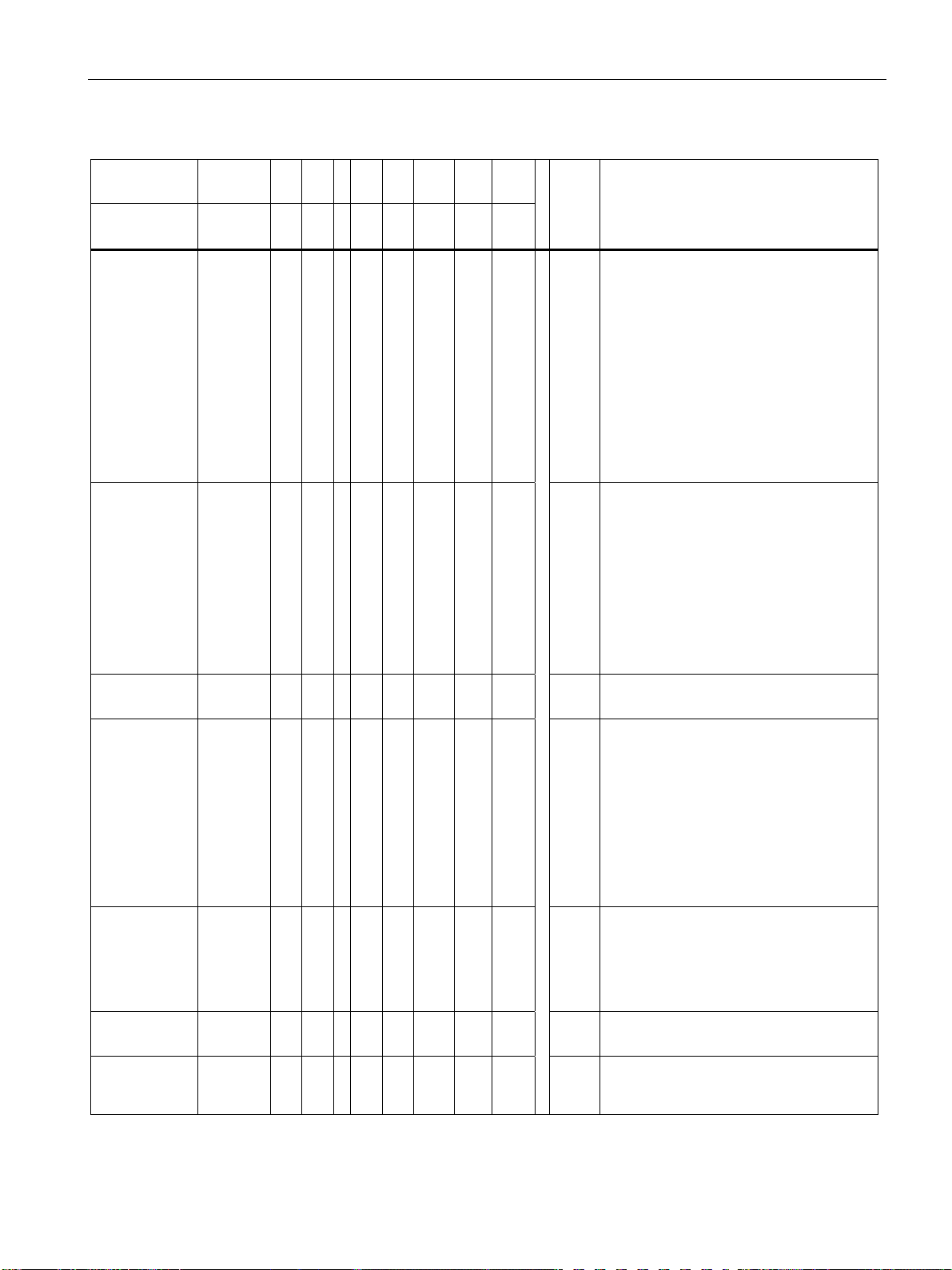
A
1.6 Article No. scheme
Digit of the
rticle No.
SIRIUS timing
relay
Functional
variant
Time ranges ☐
Connection
system
Output type ☐
Supply
voltage
Frequency
range
Example 3 R P 2 5 0 5 - 1 A W 3 0 Multifunction relays with 7 time ranges;
1st - 5th 6th 7th 8th 9th 10th 11h 12th
3 R P 2 5 ☐ ☐ - ☐ ☐ ☐ ☐ 0
☐
☐
☐
☐
0
1
2
3
4
5
6
7
0
1
2
3
4
5
6
7
1
2
A
B
C
E
N
R
S
T
W
M
(GND)
B
2
3
Multifunction
ON-delay with a time range
ON-delay > 1 time range
OFF-delay with control signal
OFF-delay without control signal and
Non-volatile (positive passing make
contact)
Flasher relays asymmetrical (clock-pulse)
Start-delta (wye-delta) function (SD) with
coasting time
Star-delta (wye-delta) function (SD)
0.05 … 600 s, 1... 20 s, (SD, 30 ... 600 s
coasting time)
0.5 ... 10 s
1 ... 30 s
5 ... 100 s
1 ... 20 s (SD)
7 time ranges 0.05 s... 100 h
3 ... 60 s (SD)
4 time ranges 0.05 ... 240 s
Screw terminal
Spring-loaded terminal (push-in)
1 CO relay
2 CO relay
1 NO semiconductor contact (AC/DC)
1 NO semiconductor contact (AC/DC),
two-wire
2 NO contacts
1 relay, 2 CO contacts, positively-driven
and hard gold-plated contacts
3 NO contacts
400 ... 440 V AC
12 ... 240 V AC/DC
200 ... 240 V / 380 ... 440 V AC
24 V AC/DC
50/60 Hz AC
50/60 Hz AC/DC
screw-type terminals; 1 CO relay contact;
12 ... 240 V AC/DC; 50/60 Hz
3RP25 Time Relays
Manual, 09/2019, A5E31947765002A/RS-AC/003
9
Page 10

Introduction
1.6 Article No. scheme
3RP25 Time Relays
10 Manual, 09/2019, A5E31947765002A/RS-AC/003
Page 11
2
Note
Recycling and disposal
Dispose of existing packing material in accordance with applicable regulations or
3RP25 time relays are able to be recycled thanks to a low
For environmentally-friendly recycling and disposal of your electronic waste, please contact a
company certified for the disposal of electronic waste.
WARNING
Protection against electrically conductive contamination!
the ambient conditions. One way you can do this is to install the devices in a control cabinet
CAUTION
Protection against electrostatic charge
2.1 General safety notes
recycle it.
-pollutant manufacturing process.
The devices must be protected against conductive contamination while taking account of
with the appropriate degree of protection.
You will find more detailed information in IEC 60529, for example.
When handling and installing 3RP25 time relays, ensure that the components are protected
from being electrostatically charged. Changes to the system configuration and wiring are
only permissible while the supply voltage is switched off.
Connection of 3RP25 time relays is only permissible when the power supply is switched off.
3RP25 Time Relays
Manual, 09/2019, A5E31947765002A/RS-AC/003
11
Page 12
Safety notes
WARNING
Hazardous Voltage
Can Cause Death, Serious Injury, or Property Damage.
Intended Use of Hardware Products
WARNING
Hazardous voltage
Can Cause Death, Serious Injury, or Property Damage.
Please take note of our latest information
2.2 Intended use
2.2 Intended use
This equipment is only allowed to be used for the applications described in the catalog and
in the technical description, and only in conjunction with non-Siemens equipment and
components recommended by Siemens.
Correct transport, storage, installation and assembly, as well as careful operation and
maintenance, are required to ensure that the product operates safely and without faults.
2.3 Current information about operational safety
Important note for maintaining operational safety of your system
Systems with safety-related characteristics are subject to special operational safety
requirements on the part of the operator. The supplier is also obliged to comply with special
product monitoring measures. For this reason, we publish a special newsletter containing
information on product developments and features that are (or could be) relevant to
operation of safety-related systems. By subscribing to the appropriate newsletter, you will
ensure that you are always up-to-date and able to make changes to your system, when
necessary:
SIEMENS Newsletter (http://www.industry.siemens.com/newsletter) Subscribe to the
following newsletter under "Products & Solutions":
• Control Components and System Engineering News
3RP25 Time Relays
12 Manual, 09/2019, A5E31947765002A/RS-AC/003
Page 13
3
3.1 Device overview
3RP25 Time Relays
Manual, 09/2019, A5E31947765002A/RS-AC/003
13
Page 14

Description
3.2 Device description
3.2 Device description
Electronic timing relays are used in control, starting, and protective circuits for all switching
operations involving time delays. Their fully developed concept and space-saving, compact
design make the SIRIUS 3RP timing relays ideal modules for control cabinet, switchgear and
control manufacturers in the industry.
Thanks to their slim-line, space-saving design from 17.5 mm, 3RP25 timing relays are
especially suitable for use in smaller control boxes, such as heating, ventilation and airconditioning systems, and in compressors. All 3RP25 timing relays in this enclosure version
are suitable for snapping onto TH35 mounting rails in accordance with IEC60175.
Benefit
● Transparent program with seven basic units for the 3RP timing relay
● Logistical advantages provided by versions with wide voltage range and wide setting
range
● No tools required for assembly or disassembly on standard mounting rails
● Cadmium-free relay contacts
● Recyclable, halogen-free enclosure
● Optimum price/performance ratio
● Timing relays in 17.5 mm width offer more space in the control cabinet
● Environmentally friendly laser inscription instead of printing containing solvents
● Hard gold-plated relay contacts for optimum interaction with electronic controls
● Versions with screw-type connection or alternatively with spring-loaded/push-in
technology
3RP25 Time Relays
14 Manual, 09/2019, A5E31947765002A/RS-AC/003
Page 15

Description
3.3 Device versions
3.3 Device versions
SIRIUS 3RP25 timing relays are available in the following versions:
● Single function units, e.g. "ON-delay" function
● Multifunction units
Sizes
The overall height of 100 mm has been standardized with the other system components, and
the overall depth has been standardized for all widths to 90 mm. Refer to Section
"Dimension drawings 3RP25 devices (Page 85)" for the precise dimensions. The timing
relays are designed in two widths:
● 17.5 mm
This width is used predominantly for relays with one contact element (e.g. 1 CO contact)
and 8 possible connecting terminals.
● 22.5 mm
This width is used predominantly for relays with several contact elements (e.g. 2 CO
contacts) and 12 possible connecting terminals.
Characteristics
The features of the 3RP25 timing relay are:
● 1 CO contact (single function and multifunction with 13 functions)
● 1 NO semiconductor contact (two-wire timing relay, multifunction with 13 functions)
● 1 relay, 2 CO contacts, positively-driven (multifunction with 13 functions)
● 2 CO contacts (multifunction with 27 functions)
● 7 switchable time ranges
● Adjustable operating time from 0.05 s to 100 h
● Wide voltage range version 12 ... 240 V AC/DC
● Single function unit for the following functions:
– ON-delay with 1 or 2 CO contacts
– OFF-delay with control signal and 1 CO contact
– OFF-delay without control signal and 1 or 2 CO contacts
– Asymmetrical flasher relay (clock-pulse; pulse and interval separately adjustable) with
1 CO contact
– Star-delta (wye-delta) with 2 or 3 NO contacts, with and without overtravel function
– 2-wire ON-delay with semiconductor output
3RP25 Time Relays
Manual, 09/2019, A5E31947765002A/RS-AC/003
15
Page 16

Description
Function
- 1CO: 1 CO contact
- 1NO: 1 NO contact
- 2CO: 2 CO contacts, parallel contacts
- 1CO+1CO: 1 CO contact delayed + 1
instantaneous CO contact
- Star-delta (wye-delta) function
A
ON-delay
ON-delay
and instantaneous contact
signal
and instantaneous contact
interval
interval
and instantaneous contact
instantaneous contact
break contact with control signal)
control signal)
and instantaneous contact
with control signal)
signal)
and instantaneous contact
with control signal
control signal
and instantaneous contact
instantaneous contact
pulse
and instantaneous contact
adjustable)
adjustable)
and instantaneous contact
contact
(watchdog)
YD
Star-delta (wye-delta) function
3.3 Device versions
● Two-wire timing relays
In conjunction with contactors, they have the following advantages compared to
conventional timing relays:
– Reduced wiring
– Bounce-free control
– The solid-state output enables increased service life as there is no mechanical wear
● Multifunction timing relay with 1 CO contact and 13 functions (A-M) or 2 CO contacts and
27 functions (A-M + YD). The unit can be set as a 2 CO contact unit (2CO) or 1 CO
contact + 1 CO contact unit (1CO+1CO):
B OFF-delay with control signal OFF-delay with control signal
instantaneous contact
C ON-delay and OFF-delay with control
D Flasher relay, symmetrical, starting with
E Passing make contact, interval relay Passing make contact, interval relay
F Retriggerable interval relay with
deactivated control signal (passing
G Passing make contact with control
signal, not retriggerable, (pulse-forming
H Additive ON-delay, instantaneous OFF
I Additive ON-delay with control signal Additive ON-delay with control signal
J Flasher relay, symmetrical, starting with
K Pulse-delayed (pulse and pulse delay
L Pulse-delayed with control signal (pulse
and pulse delay adjustable)
ON-delay and OFF-delay with control signal
Flasher relay, symmetrical, starting with
Retriggerable interval relay with deactivated
control signal (passing break contact with
Passing make contact with control signal, not
retriggerable, (pulse-forming with control
Additive ON-delay, instantaneous OFF with
Flasher relay, symmetrical, starting with pulse
Pulse-delayed (pulse and pulse delay
Pulse-delayed with control signal (pulse and
pulse delay adjustable)
and
and instantaneous
and
and
M (GND) Retriggerable interval relay with
3RP25 Time Relays
16 Manual, 09/2019, A5E31947765002A/RS-AC/003
activated control signal (watchdog)
Retriggerable interval relay with activated
control signal
and instantaneous contact
Page 17

Description
3.4 Special features
3.4 Special features
Operating temperature
For operation from -25 °C to +60 °C, there are no restrictions for the control supply,
switching current, or ON time.
Time ranges
Up to 7 time ranges are available from 0.05 s to 100 h. These are as follows:
● 0.05 s - 1 s
● 0.5 s - 10 s
● 5 s - 100 s
● 0.5 min - 10 min
● 0.05 h - 1 h
● 0.5 h - 10 h
● 5 h - 100 h
Wide voltage range
All functions can be operated with a wide voltage range 12 ... 240 V AC/DC.
Electrical service life
The electrical service life with contactor load (e.g. 3RT1016 contactor) is 10 million operating
cycles.
The electrical service life at 230 V AC voltage, utilization category AC-15/3 A is 100 000
operating cycles.
Start/control contact
With functions requiring a continuously active supply voltage at terminals A1/A2, the timer
function is started by a control signal at terminal B1.
3RP25 Time Relays
Manual, 09/2019, A5E31947765002A/RS-AC/003
17
Page 18

Description
3.4 Special features
Special functions
● Function "flashing, asymmetrical": Pulse and interval can be adjusted separately. (clock-
pulse)
● Function "flashing, symmetrical": the pulse/interval ratio is 1:1. (flashing)
● With the "OFF-delay without control signal" function, timing is started when the time relay
is disconnected from the supply voltage.
● On the 3RP25 time relay with 7 switchable time ranges, there is a switch position
means "continuous (unlimited) time". If this setting is selected with the "ON-delay"
function, the output relay never connects after the supply voltage is applied (OFF
function). With the function "passing make contact", the output relay always remains on
(ON function). This can be used for test purposes.
● If the control signal in interrupted when the "additive ON-delay with control signal"
function has been selected, timing stops and continues when the control signal is closed
again.
This function is not non-volatile and requires a continuous control signal supply.
● With the function "pulse-forming with control signal", an activated control signal triggers
an adjustable timing period. The control signal can be shorter or longer than the desired
operating time.
∞. This
3RP25 Time Relays
18 Manual, 09/2019, A5E31947765002A/RS-AC/003
Page 19
Description
NOTICE
Potential property damage.
3.5 Notes on configuration
3.5 Notes on configuration
Prerequisites
Only change the time setting range or function in the de-energized state.
Start input
The control signal at B1 may only be applied when the supply voltage is already present at
A1 / A2.
Same potential
The same potential must be applied at terminals A1 and B1. This means the supply voltage
and the control signal must be identical.
Combination voltage
With combination voltage versions, only one voltage range must ever be connected at one
time. Never apply both control voltages simultaneously.
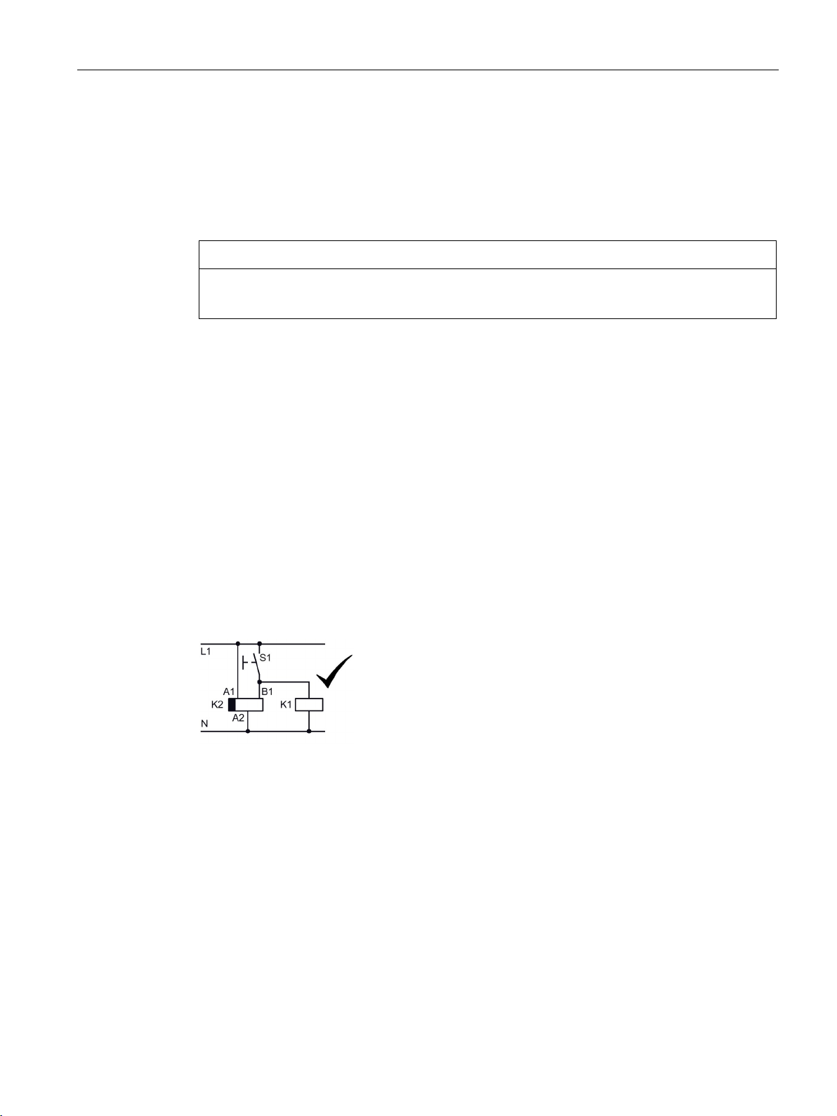
Parallel load at the start contact
A circuit with parallel load is permissible with AC and DC on the 3RP25 timing relays.
Positively-driven contacts
When using positively driven contacts with 3RP2502-xRW30, the same power supply /
voltage must be used for both changeover contacts.
3RP25 Time Relays
Manual, 09/2019, A5E31947765002A/RS-AC/003
19
Page 20

Description
3.6 Area of application
3.6 Area of application
Functions
Time relays with ON-delay
● Interference pulse suppression (gating of interference pulses)
● Gradual startup of motors so as not to overload the power supply
Time relays with OFF-delay
● Generation of overtravel functions following removal of voltage
● Gradual, delayed shutdown, e.g. of motors or fans to allow a plant to be shut down
selectively
Star-delta (wye-delta) time relay
● Motor changeover from star (wye) to delta with a changeover delay of 50 ms to prevent
interphase short-circuit
Multifunction time relays
● Maximum flexibility, with a device for every application
Additive ON-delay, instantaneous OFF with control signal
● e.g. for the control of cyclical machine lubrication operations dependent on operating
hours
Flasher relay, symmetrical, starting with pulse
● Gradual adjustability of longitudinal feed on punching/embossing machines
Pulse-delayed relay
● Time relay with which the timing period starts when the control supply voltage is applied
and the output briefly switches to the working position after expiry of the set time delay
Pulse-delayed relay with control signal
● Time relay with which the timing period starts when the supply voltage and the control
signal are applied, and the output briefly switches to the working position after expiry of
the set time delay
3RP25 Time Relays
20 Manual, 09/2019, A5E31947765002A/RS-AC/003
Page 21

Description
3.6 Area of application
Retriggerable interval relay with activated control signal and instantaneous contact
(watchdog relay)
● Cyclic monitoring of a start contact (dead man's circuit)
Supply voltage present at A1/A2. When the control signal is applied, the relay switches
immediately to the working position. The relay switches to idle after the set time
independently of the presence of the control signal (watchdog function). The time delay is
restarted each time the control signal is applied.
Retriggerable interval relay with deactivated control signal
● Time relay for which the output switches immediately to the working position when the
supply voltage is applied and the control signal is deactivated. The time starts and the
output switches to the idle position after the set delay has expired. The time function is
restarted each time the control signal is switched off.
ON and OFF-delay
● Closed-loop control (pre-travel and overtravel) of heating or cooling systems
Passing make contact
● Forced ventilation of rooms
● Stairwell lighting and elevator lighting
Passing break contact
● Emptying a conveyor belt / chip conveyor at end of process
3RP25 Time Relays
Manual, 09/2019, A5E31947765002A/RS-AC/003
21
Page 22
Description
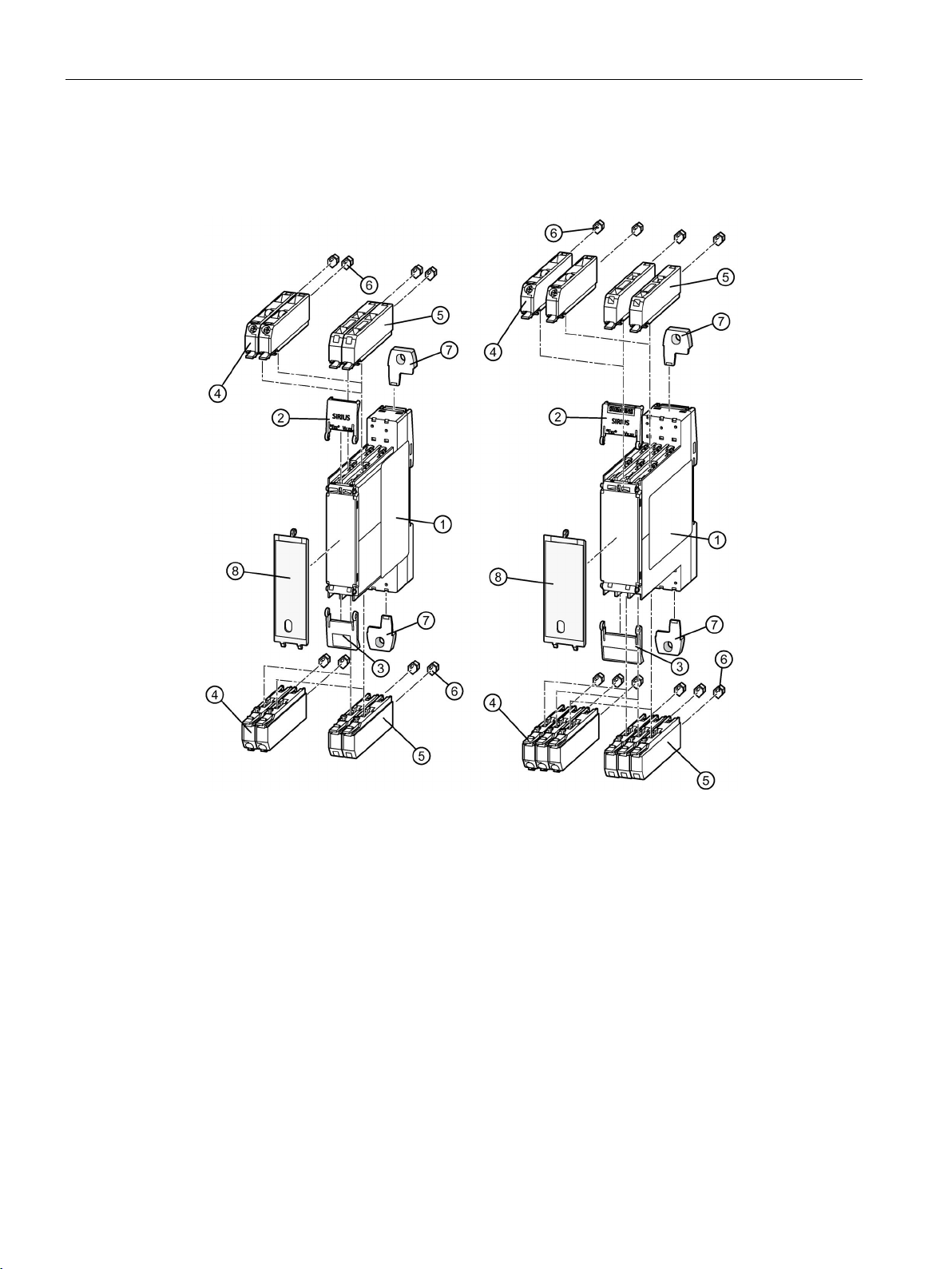
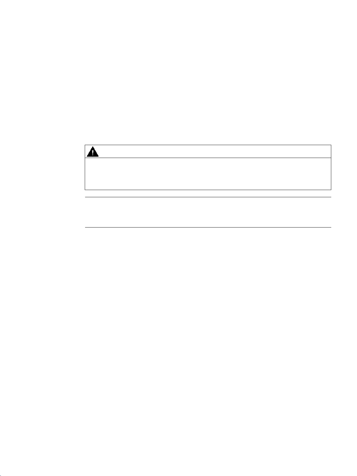
①
Basic unit
②
Top cover flap
③
Bottom cover flap
④
Spring-loaded terminals (push-in) 2-pole 1 x 2.5 mm²
⑤
Screw-type terminals 2-pole 1 x 2.5 mm²
⑥
Coding pins (accessories, to be ordered separately)
⑦
Push-in lugs for wall mounting (accessories, to be ordered separately)
⑧
Sealable covers (accessories, to be ordered separately)
3.7 Overview of 3RP25 components and accessories
3.7 Overview of 3RP25 components and accessories
You can find details and article numbers for the accessories in the Section Accessories
(Page 89).
3RP25 Time Relays
22 Manual, 09/2019, A5E31947765002A/RS-AC/003
Page 23
4
WARNING
Hazardous voltage!
Causes electric shock and burns when touched.
Note
Following figures similar!
The figures shown below (size, accessories, add
4.1 Warning notices
Warning notices before installation, wiring, and commissioning
Turn off and lock out all power supplying this device before working on this device.
-ons, etc.) are similar.
3RP25 Time Relays
Manual, 09/2019, A5E31947765002A/RS-AC/003
23
Page 24
Mounting
4.2 Terminal coding
4.2 Terminal coding
You can provide the terminals with coding pins (3ZY1440-1AA00). This helps you to avoid
errors when replacing the terminals.
3RP25 Time Relays
24 Manual, 09/2019, A5E31947765002A/RS-AC/003
Page 25
Mounting
Step
Instructions
Figure
standard mounting rail
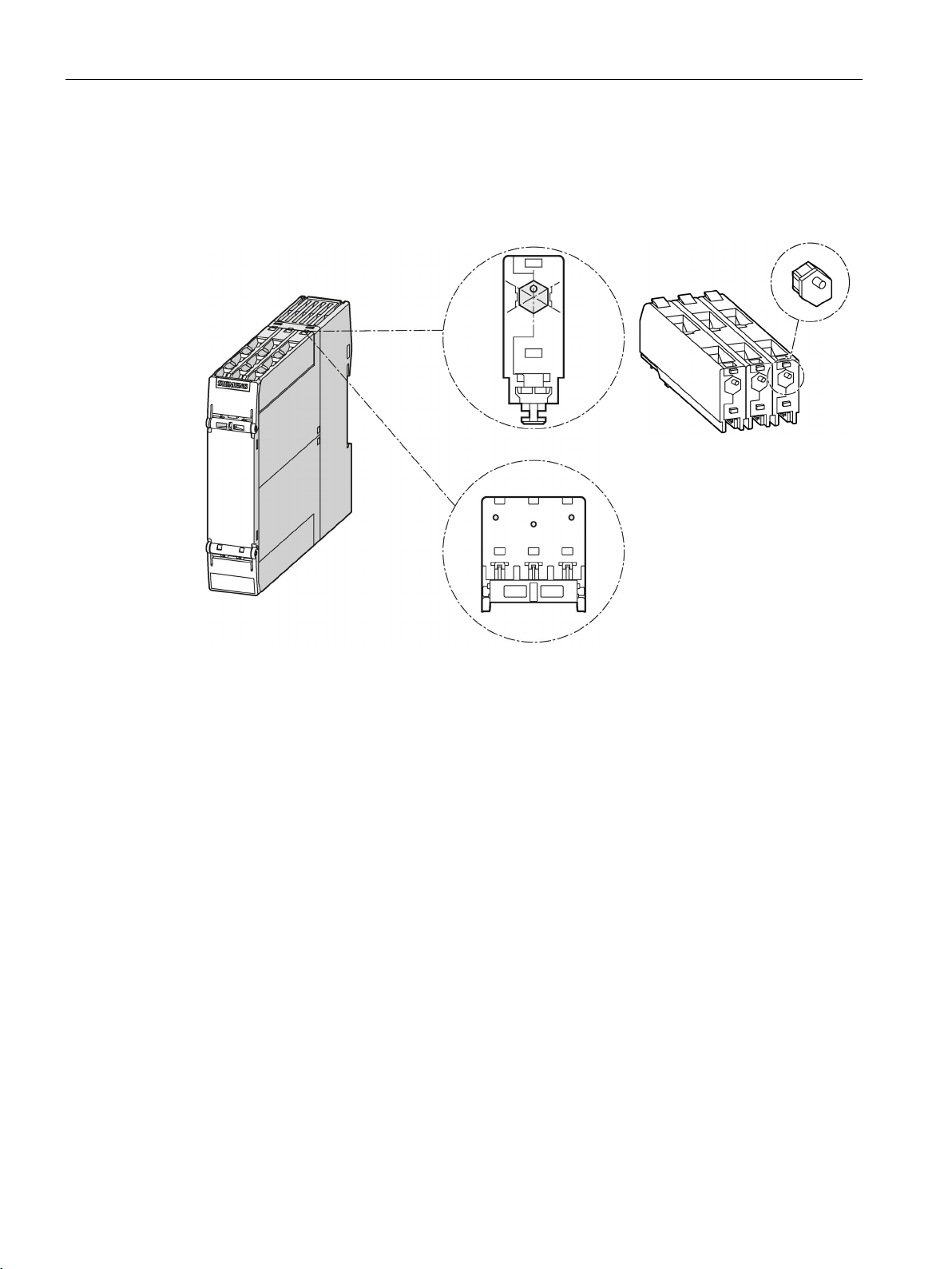
4.3 Mounting the devices on a standard mounting rail
4.3 Mounting the devices on a standard mounting rail
Requirements
● A horizontal 35-mm wide mounting rail in accordance with DIN EN 60715 has been
properly secured at the installation location.
Procedure
The figures show 22.5 mm devices. The 17.5 mm devices are mounted correspondingly.
1 Hang the back of the device
onto the upper edge of the
2 Press the lower half of the
device against the rail until the
device engages
3RP25 Time Relays
Manual, 09/2019, A5E31947765002A/RS-AC/003
25
Page 26
Mounting
WARNING
Hazardous Voltage
Can Cause Death, Serious Injury, or Property Damage.
Step
Instructions
Figure
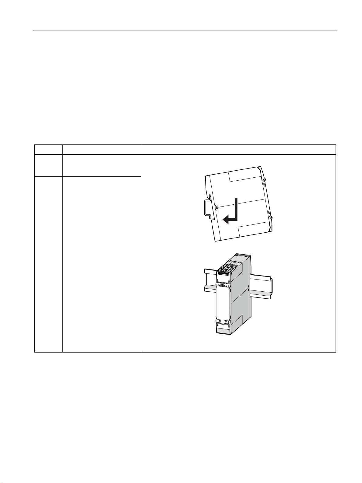
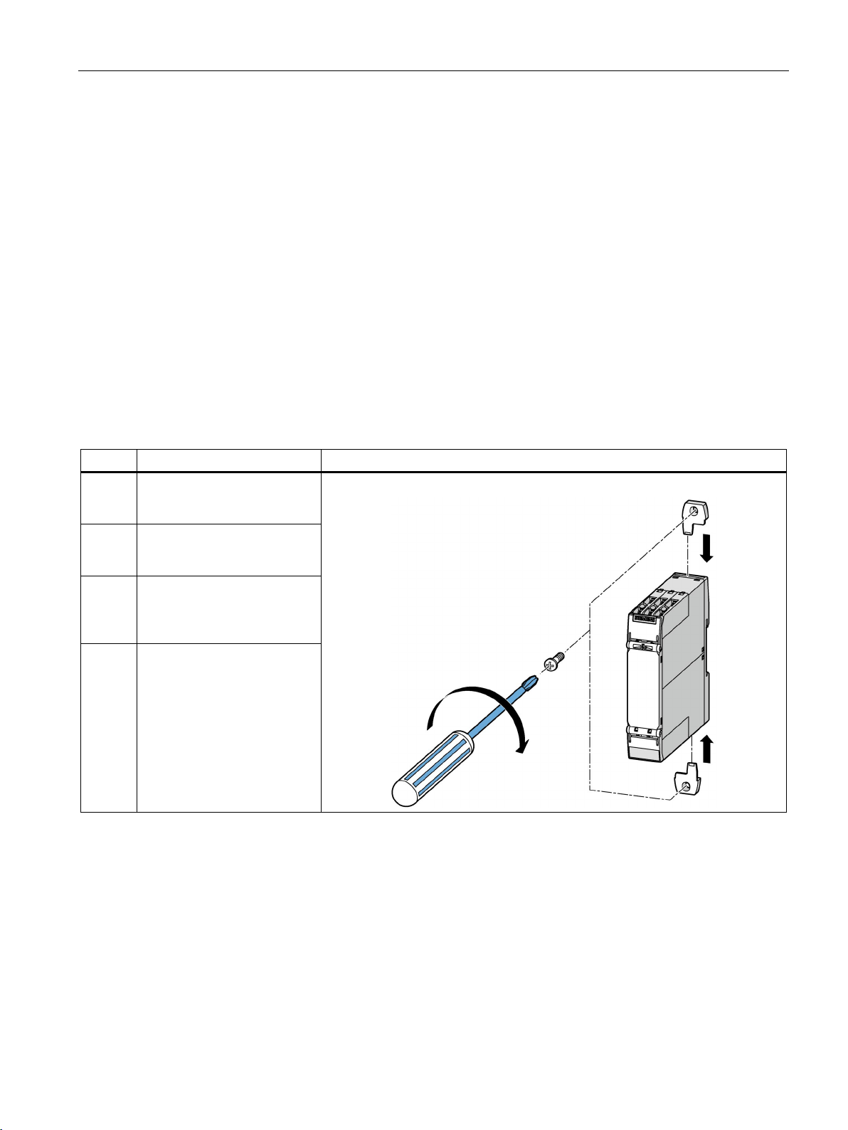
1
Press the device downwards.
from the standard mounting rail.
4.4 Removing devices from a standard mounting rail
4.4 Removing devices from a standard mounting rail
Before starting work, therefore, disconnect the system and devices from the power supply.
Requirements
● The terminals have been removed or disconnected.
Procedure
2 Pull the lower half of the device away
3 Lift the device from the upper edge of
the standard mounting rail.
3RP25 Time Relays
26 Manual, 09/2019, A5E31947765002A/RS-AC/003
Page 27
Mounting
Step
Instructions
Figure
the device until they engage.
fastening.
lugs.
4.5 Mounting the devices on a level surface
4.5 Mounting the devices on a level surface
Requirements
Please note the following requirements for mounting on a level surface:
● A vertical mounting surface is recommended for the time relay.
● Two properly executed drill holes with thread or plug on the level surface. For details of
the distances between the drilled holes, please refer to the relevant dimension drawings
in the chapter "Dimension drawings 3RP25 devices (Page 85)".
● Two screws to fit the M4 x 12 holes in accordance with DIN 784.
● Two fixing lugs in accordance with the article number in the accessories list in the Section
"Accessories for 3RP25 (Page 89)".
Procedure
1 Insert the securing brackets
into the openings provided on
2 Hold the device up to the level
surface prepared for screw
3 Insert the head screws
through the corresponding
elongated holes in the fixing
4 Screw the device securely
onto the level surface.
Tightening torque: 1 Nm
3RP25 Time Relays
Manual, 09/2019, A5E31947765002A/RS-AC/003
27
Page 28

Mounting
WARNING
Hazardous Voltage
Can Cause Death, Serious Injury, or Property Damage.
Step
Instructions
Figure
1
Hold the device firmly.
2 Unscrew the cap screws.
surface.
4.6 Disassembling the devices from a level surface
4.6 Disassembling the devices from a level surface
Before starting work, therefore, disconnect the system and devices from the power supply.
Requirements
● The terminals have been removed or disconnected.
Procedure
3 Lift the device from the level
4 Remove the securing brackets
from the device.
3RP25 Time Relays
28 Manual, 09/2019, A5E31947765002A/RS-AC/003
Page 29

Mounting
Step
Instructions
Figure
and fold the cover up
4.7 Mounting the sealable cover
4.7 Mounting the sealable cover
The sealable cover (3ZY1321-1AA00 for 17.5 mm devices, 3ZY1321-2AA00 for 22.5 mm
devices) can be used to secure the time range switch and the function selector switch as
well as the operating time adjustment switch against unauthorized or unintended
readjustment.
Mounting the sealable cover
1 Attach the hooks on the cover
to the openings on the device
2 Seal the cover to secure it
against unauthorized removal.
Sealing wire diameter, max.:
2 mm
3RP25 Time Relays
Manual, 09/2019, A5E31947765002A/RS-AC/003
29
Page 30

Mounting
Step
Instructions
Figure
screwdriver.
4.8 Attaching set of labels (multifunction)
4.8 Attaching set of labels (multifunction)
A set of stickers is available for labeling the functions set on the 3RP2505 solid-state time
relay, multifunction unit, depending on the version (with 1 CO contact, 13 functions, with 1
NO contact/semiconductor output, 13 functions, with 2 CO contacts, 27 functions).
Attaching the set of stickers (only for multifunctionality)
1 Set the desired function on
the time range and function
selector switch using a
2 Take the corresponding
sticker for labeling the
function from the set of
stickers, and stick it directly
above the function selector
switch (A-M). Function, see
Function table multifunction
(3RP2505) (Page 69)
3RP25 Time Relays
30 Manual, 09/2019, A5E31947765002A/RS-AC/003
Page 31

5
NOTICE
Risk of property damage
5.1 Terminal assignment
Location of the connections
The inside faces of the terminal covers are labeled with the designations of the relevant
terminals. The position of the label corresponds to the position of the respective terminal.
When using the terminal blocks, you must observe the correct position of the blocks (see
inside of cover).
3RP25 Time Relays
Manual, 09/2019, A5E31947765002A/RS-AC/003
Figure 5-1 Upper terminal cover
31
Page 32

Connection
5.1 Terminal assignment
Figure 5-2 Lower terminal cover
3RP25 Time Relays
32 Manual, 09/2019, A5E31947765002A/RS-AC/003
Page 33

Connection
Time relay version
Inscription of the terminal cover
Control circuit/control circuit supply (at the top of the device)
Single function
24 V AC/DC
12 ... 240 V AC/DC
200 ... 240 V / 380 ... 440 V AC
Multifunction
24 V AC/DC
12 ... 240 V AC/DC
400 to 440 V AC
5.1 Terminal assignment
Terminal cover
Depending on the version of the 3RP25 time relay, the device will have the following
connections:
•
• (3RP25..-..B..)
•
• (3RP25..-...W...)
•
• (3RP25..-..M..)
•
• (3RP250.-..B..)
3RP25 Time Relays
Manual, 09/2019, A5E31947765002A/RS-AC/003
•
• (3RP250.-..W..)
•
• (3RP250.-..T..)
33
Page 34

Connection
Time relay version
Inscription of the terminal cover
Output contacts/output relays (at the bottom of the device)
Single and
multifunction
5.1 Terminal assignment
3RP25 Time Relays
34 Manual, 09/2019, A5E31947765002A/RS-AC/003
Page 35

Connection
Note
The terminals A2 are connected internally. This means A2 can simply be looped on from
device to device.
① ② ③ ④ ⑤
3RP2525 - .AW30
5.2 Position of the connecting terminals
5.2 Position of the connecting terminals
3RP2527 - .EW30 3RP2560 - .SW30
3RP2505 - .AB30
3RP2505 - .AW30
3RP25 Time Relays
Manual, 09/2019, A5E31947765002A/RS-AC/003
3RP2535 - .AW30 3RP2511 - .AW30
3RP2512 - .AW30
3RP2513 - .AW30
35
Page 36

Connection
⑥ ⑦ ⑧ ⑨ ⑩
3RP2576 - .NW30
3RP2540 - .AW30
3RP2540 - .BW30
3RP2505 - .BW30
3RP2525 - .BW30
5.2 Position of the connecting terminals
3RP2574 - .NW30
3RP2540 - .AB30
3RP2540 - .BB30
3RP2505 - .BB30
3RP2525 - .BB30
3RP25 Time Relays
36 Manual, 09/2019, A5E31947765002A/RS-AC/003
Page 37

Connection
⑪ ⑫ ⑬ ⑭ ⑮
3RP2576 - .NM20
5.2 Position of the connecting terminals
3RP2574 - .NM20
3RP2555 - .AW30 3RP2505 - .CW30 3RP2505 - .BT20 3RP2505-.RW30
3RP25 Time Relays
Manual, 09/2019, A5E31947765002A/RS-AC/003
37
Page 38

Connection
Specification and value
in the case of removable terminals with
screw-type terminals
Specification and value
in the case of removable terminals with
spring-loaded terminals
(push-in terminals)
2 x 20 ... 14
1)
alternative, you are advised to use end sleeves without plastic sleeves
5.3 Connection data for terminals
5.3 Connection data for terminals
Screwdriver
Rigid cable
Flexible conductor with end
sleeve
Flexible cable
AWG 1 x 20 ... 12
Cross-tip screwdriver
Size: PZ 1x80 (⌀ 4.5 mm)
Torque: 0.6 … 0.8 Nm (5.2 ... 7.0 lb/inch)
A = 10 mm
1 x 0.5 ... 4.0 mm²
2 x 0.5 ... 2.5 mm²
A = 10 mm
1 x 0.5 ... 4.0 mm²
2 x 0.5 ... 1.5 mm²
Not permissible A = 10 mm
Screwdriver (3RA2908-1A)
Size: 3 mm for operating the springs
DIN 5264-A; 0.5 x 3
A = 10 mm
1 x 0.5 ... 4.0 mm²
A = 10 mm
1 x 0.5 ... 2.5 mm²
1)
1 x 0.5 ... 4.0 mm²
1 x 20 ... 12
When 2 x 1.0 mm² end sleeves with a plastic sleeve are used, space problems may arise with the sleeves; as an
3RP25 Time Relays
38 Manual, 09/2019, A5E31947765002A/RS-AC/003
Page 39

Connection
WARNING
Hazardous voltage
Can Cause Death, Serious Injury, or Property Damage.
Step
Instructions
Figure
screw-type terminal until it engages.
2
Hold the cable in the screw-type terminal.
3
Tighten the screw with a torque of 0.8 to 1.2 N.
5.4 Connecting the screw-type terminals
5.4 Connecting the screw-type terminals
Before starting work, therefore, disconnect the system and devices from the power supply.
Requirements
● Cross-tip screwdriver size PZ 1 x 80.
● For suitable connection cross-sections of the cables, see the chapter "Connection data
for terminals (Page 38)".
Procedure
1 Insert the relevant cable into square on the
4 Pull on the cable to ensure it is screwed tight.
3RP25 Time Relays
Manual, 09/2019, A5E31947765002A/RS-AC/003
39
Page 40

Connection
WARNING
Hazardous Voltage
Can Cause Death, Serious Injury, or Property Damage.
Step
Instructions
Figure
1
Unscrew the screw of the screw-type terminal.
5.5 Disconnecting the screw-type terminals
5.5 Disconnecting the screw-type terminals
Before starting work, therefore, disconnect the system and devices from the power supply.
Requirements
● Cross-tip screwdriver size PZ 1 x 80
Procedure
2 Remove the cable from the unscrewed
screw-type terminal.
3RP25 Time Relays
40 Manual, 09/2019, A5E31947765002A/RS-AC/003
Page 41

Connection
5.6 Wiring rules for spring-loaded terminals (with push-in technology)
5.6 Wiring rules for spring-loaded terminals (with push-in technology)
Notes on handling spring-loaded terminals with push-in technology
The terminal area of the spring-loaded terminals is rectangular, and the maximum overall
dimensions of the conductor to be wired must not exceed 2.4 x 2.8 mm.
Attention must be paid to the orientation of the terminal area, which may call for vertical
fitting of rectangularly crimped cables.
To make optimum use of available terminal area, you are advised to choose a form of
crimping that creates a corresponding rectangular contour. Trapezoidal crimping is generally
very highly suitable in this case.
When use is made of a cable that utilizes the full overall height, the terminal's spring is
deflected to the maximum. Therefore, removal of this cable may become a problem because
it requires further deflection of the spring.
3RP25 Time Relays
Manual, 09/2019, A5E31947765002A/RS-AC/003
41
Page 42

Connection
WARNING
Hazardous voltage
Can Cause Death, Serious Injury, or Property Damage.
Step
Instructions
Figure
it will go.
5.7 Connect the spring-loaded terminal (push-in)
5.7 Connect the spring-loaded terminal (push-in)
Before starting work, therefore, disconnect the system and devices from the power supply.
The spring-type (push-in) terminals allow wiring without tools for rigid conductors or
conductors equipped with end sleeves.
For wiring finely stranded or stranded conductors without end sleeves on spring-type
(push-in) terminals, a screwdriver is required to open the spring-type terminals.
Requirements
● 0.5 x 3 mm screwdriver DIN 5264 (for finely-stranded conductors only).
● For suitable connection cross-sections of the cables, see the chapter "Connection data
for terminals (Page 38)".
Procedure
Table 5- 1 Rigid conductors or conductors equipped with end sleeves
1 Insert the cable into the oval opening as far as
2 Pull on the cable to ensure it is tight.
3RP25 Time Relays
42 Manual, 09/2019, A5E31947765002A/RS-AC/003
Page 43

Connection
Step
Instructions
Figure
opening to open the terminal (oval opening).
opening and remove the screwdriver.
5.7 Connect the spring-loaded terminal (push-in)
Table 5- 2 Finely stranded cables without end sleeve
1 Insert the screwdriver in the rectangular
2 Insert the cable as far as it will go into the oval
3 Pull on the cable to ensure it is tight.
3RP25 Time Relays
Manual, 09/2019, A5E31947765002A/RS-AC/003
43
Page 44

Connection
WARNING
Hazardous voltage
Can Cause Death, Serious Injury, or Property Damage.
Step
Instructions
Figure
engages.
2
Remove the cable from the oval opening.
5.8 Disconnect the spring-loaded terminal (push-in)
5.8 Disconnect the spring-loaded terminal (push-in)
Before starting work, therefore, disconnect the system and devices from the power supply.
Requirements
● Screwdriver DIN 5264 of the size 0.5 x 3 mm
Procedure
1 Insert the screwdriver into the rectangular
opening of the spring-loaded terminal until it
3 Remove the screwdriver.
3RP25 Time Relays
44 Manual, 09/2019, A5E31947765002A/RS-AC/003
Page 45

Connection
WARNING
Hazardous voltage
Can Cause Death, Serious Injury, or Property Damage.
Step
Instructions
Figure
rail of the device.
5.9 Attaching the terminals
5.9 Attaching the terminals
Before starting work, therefore, disconnect the system and devices from the power supply.
Requirements
You must have removed the terminals, for the purpose of replacing a device, for example.
Procedure when plugging in the terminals
1 Insert the detachable terminals into the guide
2 Slide the detachable terminals back until they
audibly engage.
3RP25 Time Relays
Manual, 09/2019, A5E31947765002A/RS-AC/003
45
Page 46

Connection
WARNING
Hazardous voltage
Can Cause Death, Serious Injury, or Property Damage.
Step
Instructions
Figure
1
Press the clip of the terminals upwards.
2
Pull the terminals out to the front.
5.10 Removing the terminals
5.10 Removing the terminals
Before starting work, therefore, disconnect the system and devices from the power supply.
Removing terminals from the device
3 Lift the terminals out of the guide rail of the
device.
3RP25 Time Relays
46 Manual, 09/2019, A5E31947765002A/RS-AC/003
Page 47

Connection
Step
Instructions
Figure
1
Unscrew the screw of the screw-type terminal.
Step
Instructions
Figure
opening.
2 Remove the cable from the oval opening.
5.10 Removing the terminals
Screw terminals: Disconnecting the conductor
2 Remove the cable from the unscrewed
screw-type terminal.
Spring-loaded terminal (push-in): Disconnecting the conductor
1 Insert the screwdriver into the rectangular
opening of the push-in terminal until it
engages. Please observe a 10° horizontal
angular deviation of the screwdriver to the oval
3 Remove the screwdriver.
3RP25 Time Relays
Manual, 09/2019, A5E31947765002A/RS-AC/003
47
Page 48

Connection
5.10 Removing the terminals
3RP25 Time Relays
48 Manual, 09/2019, A5E31947765002A/RS-AC/003
Page 49

6
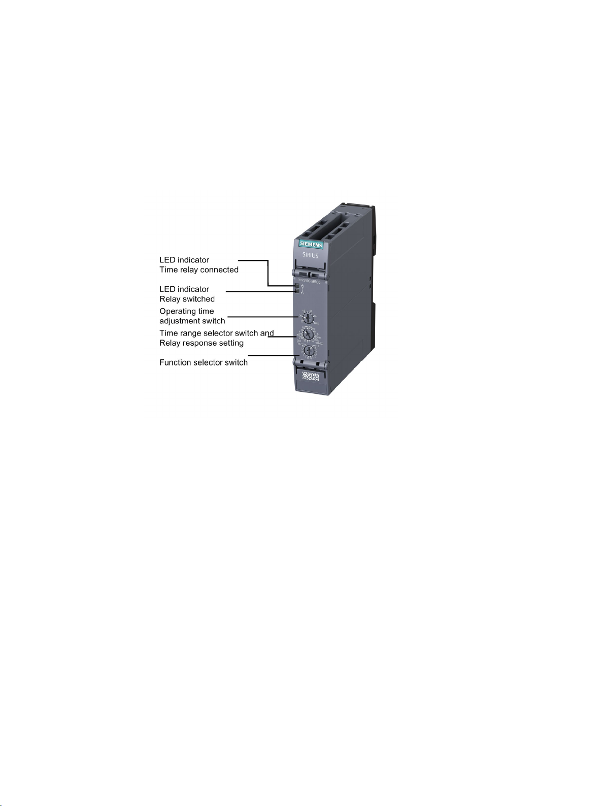
①
Top cover flap
②
LED statuses
③
Operating time adjustment switch for fine adjustment
④
Time range selector switch
⑤
Function circuit diagram lasered on enclosure
⑥
Terminal cover at bottom
⑦
DataMatrix code
⑧
Device identification label
⑨
Terminal cover top, inscription on inside
⑩
Control supply voltage specification
⑪
Terminal labeling of the control supply voltage
⑫
Terminal cover top, inscription on inside
⑬
Terminal labeling of the output contacts
⑭
Time relay article number (MLFB)
6.1 Structure
3RP25 Time Relays
Manual, 09/2019, A5E31947765002A/RS-AC/003
49
Page 50

Single function devices
Note
Changes to the set time (time range and operating time) do not become effective until the
su
Work step
Setting graphic
Process description
One time range
Several time ranges
②
6.2 Time setting single function unit
6.2 Time setting single function unit
Relay with single function
Operating time setting
The desired time range is set with the time range selector switch.
The desired operating time is set precisely with the operating time adjustment switch.
pply voltage is applied again.
Procedure
Let us suppose you wish to set a duration of 50 seconds:
①
①
Turn the operating time adjustment switch to the
setting value 50s with a screwdriver.
Operating time adjustment
switch
Turn the time range selector switch to 100s with a
screwdriver. This means that operating times up to
100 seconds can be set.
Time range selector switch
Turn the operating time adjustment switch for fine
adjustment to 50 %. This means 50 % of the
maximum value (50 % of 100 seconds =
50 seconds) is set.
Operating time adjustment
3RP25 Time Relays
50 Manual, 09/2019, A5E31947765002A/RS-AC/003
switch
Page 51

Single function devices
Function
Function chart
Circuit diagram
Time relay
1 CO contact
6.3 ON-delay
6.3 ON-delay
3RP2511 / 3RP2512 / 3RP2513 time relay
The time relay contains 1 CO contact.
Each relay has a fixed time range:
● 0.5 s - 10 s (3RP2511)
● 1.5 s - 30 s (3RP2512)
● 5 s - 100 s (3RP2513)
Function table
ON-delay
3RP2511-.AW30
3RP2512-.AW30
3RP2513-.AW30
3RP25 Time Relays
Manual, 09/2019, A5E31947765002A/RS-AC/003
51
Page 52

Single function devices
Note
The desired
Note
Changes to the time range (time range and operating time) only take effect if made in the
deenergized state.
Function
Function chart
Circuit diagram
Time relay
1 CO contact
2 CO contacts
6.3 ON-delay
3RP2525 time relay
The time relay is optionally available with 1 or 2 CO contacts.
7 time ranges can be set with the time range selector switch:
● 0.05 s - 1 s
● 0.5 s - 10 s
● 5 s - 100 s
● 0.5 min - 10 min
● 0.05 h - 1 h
● 0.5 h - 10 h
● 5 h - 100 h
operating time is set precisely with the operating time adjustment switch.
Function table
ON-delay
ON-delay
3RP2525-1AW30
3RP2525-2AW30
3RP2525-1BB30
3RP2525-1BW30
3RP2525-2BB30
3RP2525-2BW30
3RP25 Time Relays
52 Manual, 09/2019, A5E31947765002A/RS-AC/003
Page 53

Single function devices
Note
The desired operating time is set precisely with the operating time adjustment switch.
Note
Rated operational current, residual current in the case of a non-switched output, and voltage
drop in the case of a switched output must be taken into account. You can find the values in
the
Function
Function chart
Circuit diagram
Time relay
1 NO semiconductor contact (two-wire time relay)
6.3 ON-delay
3RP2527 time relay - two-wire time relay
The two-wire time relay is connected in series with the load. Timing begins after application
of the control supply voltage. The semiconductor output then becomes conducting, and the
load is under power.
4 time ranges can be set with the time range selector switch:
● 0.05 s - 1 s
● 0.2 s - 4 s
● 1.5 s - 30 s
● 12 s - 240 s
Function table
ON-delay
technical specifications (Page 83).
3RP2527-1EW30
3RP2527-2EW30
3RP25 Time Relays
Manual, 09/2019, A5E31947765002A/RS-AC/003
53
Page 54

Single function devices
Note
The desired operating time is set precisely with the operating time adjustment switch.
Function
Function chart
Circuit diagram
Time relay
1 CO contact
6.4 OFF-delay
6.4 OFF-delay
3RP2535 time relay - OFF-delay with control signal
The time relay contains 1 CO contact.
A continuous supply voltage (A1/A2) is present on the time relay. If a control signal is applied
to B1, the output relay switches over. The set operating time starts when the control signal is
switched off. A minimum ON duration of ≥ 35 ms must be observed. If the control signal is
applied again after the time has started, the time is reset. If the control signal is withdrawn,
the time starts again (retriggerable).
7 time ranges can be set with the time range selector switch:
● 0.05 s - 1 s
● 0.5 s - 10 s
● 5 s - 100 s
● 0.5 min - 10 min
● 0.05 h - 1 h
● 0.5 h - 10 h
● 5 h - 100 h
Function table
OFF-delay with control signal
3RP2535-1AW30
3RP2535-2AW30
3RP25 Time Relays
54 Manual, 09/2019, A5E31947765002A/RS-AC/003
Page 55

Single function devices
Note
The desired operating time is set
Note
Changes to the time range (time range and operating time) only take effect if made in the
deenergized state.
6.4 OFF-delay
3RP2540 time relay - OFF-delay/positive passing make contact without control signal
The time relay is optionally available with 1 or 2 CO contacts.
The time relay switches over when the control supply voltage is applied. The operating time t
starts when the control supply voltage is disconnected. The relay switches back to the idle
state when t has elapsed. It is ensured that if the minimum ON duration is not observed
either timing will not start or, if the time has started, it will always be completed in an orderly
fashion. Users can rely on intermediate states of the functional sequence, such as "no relay
dropout", being detected. If the control supply voltage is applied again after the time has
started, the time is reset. When the control supply voltage is withdrawn, the time starts again
(retriggerable).
7 time ranges can be set using a time range and function selector switch:
● 0.05 s - 1 s
● 0.15 s - 3 s
● 0.5 s - 10 s
● 1.5 s - 30 s
● 0.05 min (3 s) - 1 min (60 s)
● 5 s - 100 s
● 0.5 min (30 s) - 10 min (600 s)
precisely with the operating time adjustment switch.
3RP25 Time Relays
Manual, 09/2019, A5E31947765002A/RS-AC/003
55
Page 56

Single function devices
Work step
Setting graphic
Process description
6.4 OFF-delay
Function setting
2 functions can be selected for time relays of this type. Depending on the function required,
the left or right display must be pre-selected.
①
②
Turn the time range and function selector switch to
the desired time range with a screwdriver. Due to
the choice of the two functions, the time ranges
are arranged to the left and right respectively.
left (function N) = OFF-delay without control signal
right (function O) = positive passing make contact
without control signal
Turn the operating time adjustment switch for fine
adjustment to the required value.
3RP25 Time Relays
56 Manual, 09/2019, A5E31947765002A/RS-AC/003
Page 57

Single function devices
Function
Function chart
Circuit diagram
Time relay
1 CO contact
2 CO contacts
6.4 OFF-delay
Function table
OFF-delay without control signal
- Function N
positive passing make contact without
control signal
- Function O
OFF-delay without control signal
- Function N
positive passing make contact without
control signal
- Function O
3RP2540-1AB30
3RP2540-2AB30
3RP2540-1AW30
3RP2540-2AW30
3RP2540-1BB30
3RP2540-2BB30
3RP2540-1BW30
3RP2540-2BW30
3RP25 Time Relays
Manual, 09/2019, A5E31947765002A/RS-AC/003
57
Page 58

Single function devices
Note
The desired operating time is set precisely with the operating time adjustment switch.
Note
Changes to the time range (time range and operating time) only take effect if made in the
deenergized
Function
Function chart
Circuit diagram
Time relay
1 CO contact
6.5 Flasher relay asymmetrical (clock generator)
6.5 Flasher relay asymmetrical (clock generator)
3RP2555 time relay with control signal
The time relay contains 1 CO contact.
The interval and the pulse time of the clock generator and time ranges can each be
adjustable separately. The clock pulse function starts with the interval.
7 time ranges can be set with the time range selector switch:
● 0.05 s - 1 s
● 0.5 s - 10 s
● 5 s - 100 s
● 0.5 min - 10 min
● 0.05 h - 1 h
● 0.5 h - 10 h
● 5 h - 100 h
Function table
Flasher relay asymmetrical, starting
with interval (interval, pulse time, and
time ranges each separately
adjustable)
state.
3RP2555-1AW30
3RP2555-2AW30
3RP25 Time Relays
58 Manual, 09/2019, A5E31947765002A/RS-AC/003
Page 59

Single function devices
6.6 Star-delta (wye-delta) function
6.6 Star-delta (wye-delta) function
3RP2574 / 3RP2576 time relay
The time relay contains 2 NO contacts.
The instantaneous star contact and the time-delayed delta contact share the same contact
root. To avoid interphase short circuits, the changeover delay from star (wye) to delta is
50 ms.
Time ranges
Each relay has a fixed time range:
● 1 s - 20 s (3RP2574)
● 3 s - 60 s (3RP2576)
Note
Changes to the time range (time range and operating time) only take effect if made in the
deenergized state.
Function table
Function Function chart Circuit diagram Time relay
2 NO contacts
Star-delta (wye-delta) function
574-.NW30
3RP2
3RP2576-.NW30
3RP2574-.NM20
3RP2576-.NM20
3RP25 Time Relays
Manual, 09/2019, A5E31947765002A/RS-AC/003
59
Page 60

Single function devices
Note
Changes to the time range (time range and operating time) only take effect if made in the
deenergized state.
Function
Function chart
Circuit diagram
Time relay
3 NO contacts
6.7 Star-delta (wye-delta) function with coasting time (idling)
6.7 Star-delta (wye-delta) function with coasting time (idling)
3RP2560 time relay
The time relay contains 3 NO contacts.
Star-delta (wye-delta) time:
● 1 s - 20 s
Coasting time:
● 30 s - 600 s
Function table
Star-delta (wye-delta) function with
overtravel function2)(idling)
2)
Function charts for the different operation options of the 3RP2560 - .SW30
3RP2560-1SW30
3RP2560-2SW30
3RP25 Time Relays
60 Manual, 09/2019, A5E31947765002A/RS-AC/003
Page 61

Single function devices
6.7 Star-delta (wye-delta) function with coasting time (idling)
Operation options of the time relay
Operation 1
Control signal B1 is open when supply voltage A1 is applied.
The supply voltage is applied to A1/A2 and there is no control signal on B1. This starts the
star-delta (wye-delta) (ΥΔ) time. The idling time (coasting time) is started by applying a
control signal to B1. When the set time (30 ... 600 s) has elapsed, the output relays (17/38
and 17/28) are reset. If the control signal on B1 is switched off (minimum OFF period
270 ms), a new timing is started.
Remarks:
Observe response time (dead period) of 400 ms on energizing the supply voltage until
contacts 17/18 and 17/38 close.
Operation 2
Control signal B1 is closed when supply voltage A1 is applied.
If the control signal is already present at B1 when the supply voltage is applied to A1, no
timing takes place. The timing is only started when the control signal at B1 is switched off.
3RP25 Time Relays
Manual, 09/2019, A5E31947765002A/RS-AC/003
61
Page 62

Single function devices
6.7 Star-delta (wye-delta) function with coasting time (idling)
Operation 3
Start contact B1 closes while the star time runs.
If the control signal B1 is applied again during the star time, idling time starts and the timing
is terminated normally.
Operation 4
Start contact B1 opens while delta time is running and is applied again.
If the control signal on B1 is applied again during delta time and switched off again although
the idling time has not yet elapsed, the idling time (coasting time) is reset to zero. If the
control signal is reapplied to B1, the idling time is restarted.
3RP25 Time Relays
62 Manual, 09/2019, A5E31947765002A/RS-AC/003
Page 63

Single function devices
Note
The following applies to all
6.7 Star-delta (wye-delta) function with coasting time (idling)
Application example based on standard operation (operation 1): For example, use of
3RP2560 for compressor control
Frequent starting of compressors strains the network and the machine, and increases costs
for operators. The new time relay prevents frequent starting at times when there is high
demand for compressed air. A special control circuit prevents the compressor from being
switched off immediately when the required air pressure in the tank has been reached.
Instead, the valve in the intake tube is closed and the compressor runs in "Idling" mode, that
is, in no-load operation, for a specific time which can be set from 30 ... 600 s.
If the pressure falls within this time, the motor does not have to be restarted again, but can
return to nominal load operation from no-load operation.
If the pressure does not fall within this idling time, the motor is switched off.
The pressure switch controls the timing via B1.
The supply voltage is applied at A1 and start contact B1 is open, i.e. there is no control
signal at B1 when applying the supply voltage. The pressure switch signals "too little
pressure in system" and starts the timing via terminal B1. The compressor is started, enters
star-delta (ΥΔ) operation, and fills the pressure tank.
When the pressure switch signals "sufficient pressure", the control signal B1 is applied, the
idling time (coasting time) is started, and the compressor enters no-load operation for the set
period of time from 30 ... 600 s. The compressor is then switched off. The compressor is only
restarted if the pressure switch responds again (low pressure).
operations: The pressure switch controls the timing via B1.
3RP25 Time Relays
Manual, 09/2019, A5E31947765002A/RS-AC/003
63
Page 64

Single function devices
6.7 Star-delta (wye-delta) function with coasting time (idling)
3RP25 Time Relays
64 Manual, 09/2019, A5E31947765002A/RS-AC/003
Page 65

7
①
Top cover flap
②
LED display
③
Function selector switch (multifunction)
④
Operating time adjustment switch for fine adjustment of the time range
⑤
Time range and function selector switch, selection delayed/parallel contacts
⑥
Function diagram (sticker)
⑦
Terminal cover at bottom
⑧
DataMatrix code
⑨
Device identification label
⑩
Terminal cover top, inscription on inside
⑪
Control supply voltage specification
⑫
Terminal labeling of the control supply voltage
⑬
Terminal labeling control signal
⑭
Terminal cover top, inscription on inside
⑮
Terminal labeling of the output contacts
⑯
Time relay article number (MLFB)
7.1 Structure
3RP25 Time Relays
Manual, 09/2019, A5E31947765002A/RS-AC/003
65
Page 66

Multifunction units
Note
Changes to the time range (time
deenergized state.
7.2 Time setting multifunction unit
7.2 Time setting multifunction unit
3RP2505 time relay
The time relay contains 1 or 2 CO contacts.
Time ranges
7 time ranges can be set with the time range selector switch:
● 0.05 s - 1 s
● 0.5 s - 10 s
● 5 s - 100 s
● 0.5 min - 10 min
● 0.05 h - 1 h
● 0.5 h - 10 h
● 5 h - 100 h
Operating time setting
The available time ranges are set using the time range selector switch, ensuring extremely
high setting accuracy. The set time range is indicated on the rotary switch. The desired
operating time is set precisely using an operating time adjustment switch. In the time range
"continuous" (∞), the function is implemented with an unlimited time setting. In the case of
"ON-delay" and applied supply voltage, the output relay never connects, for example, or with
"passing make contact", the output relay remains switched on continuously.
The selected function can be indicated legibly on the multifunction relay using the
appropriate stickers. You can find these stickers for labeling the set function in Section
"Attaching set of labels (multifunction) (Page 30)".
range and operating time) only take effect if made in the
3RP25 Time Relays
66 Manual, 09/2019, A5E31947765002A/RS-AC/003
Page 67

Multifunction units
Work step
Setting graphic
Process description
③
time relay is included in the scope of supply.
7.2 Time setting multifunction unit
Procedure
Let us suppose you wish to set a duration of 90 seconds:
①
②
2 CO contact variant
(2CO / 1CO+1CO)
1 CO variant (1CO)
Turn the time range selector switch to the time
range 100 s with a screwdriver. This means that
operating times up to 100 seconds can be set. As
the relay response can be optionally selected on
the 2-CO-contact variant, the time ranges are
arranged on the left and right.
Left (2CO) = 2 parallel contacts
Right (1CO+1CO) = 1 instantaneous contact,
1 delayed contact
With the 1-CO-contact variant, the time range is
given only once on the left.
Turn the operating time adjustment switch for fine
adjustment to 90%. This means 90% of the
maximum value (90 % of 100 seconds =
90 seconds) is set.
The function is set via a function selector switch,
and displayed in the adjacent window by an
identification letter.
The set function is indicated unmistakably on the
unit by a sticker with the corresponding function
diagram. A set of stickers with the function
diagrams for all functions that can be set for the
3RP25 Time Relays
Manual, 09/2019, A5E31947765002A/RS-AC/003
67
Page 68

Multifunction units
1x instantaneous contact
Note
Unless otherwise specified, the ON
described functions with control signal.
7.2 Time setting multifunction unit
2CO
2 CO contacts in parallel,
delayed contacts
1CO+1CO
2 CO contacts,
1x delayed contact
1CO - 1 CO contact
1NO - 1 semiconductor
Functions
These are set as follows using a function selector switch:
● Time relay with 1 CO contact: 13 functions (A - M)
● Time relay with 2 CO contacts: 27 functions (for both 2CO and 1CO+1CO A - M as well
as star-delta YD)
Selection of the respective function is described in the following Section (see Section
"Function table multifunction (3RP2505) (Page 69)").
duration is always at least 35 ms for all subsequently
3RP25 Time Relays
68 Manual, 09/2019, A5E31947765002A/RS-AC/003
Page 69

Multifunction units
Function
Output type
Function chart
Circuit diagram
Time relay
Identifi-
cation
letter
7.3 Function table multifunction (3RP2505)
7.3 Function table multifunction (3RP2505)
ON-delay 1 CO contact
1 NO contact /
semiconductor
1 relay, 2 CO
contacts,
positively driven
2 CO contacts
(2CO)
3RP2505 - 1A.30
3RP2505 - 2A.30
3RP2505 - 1CW30
3RP2505 - 2CW30
3RP2505 - 1RW30
3RP2505 - 2RW30
3RP2505 - 1B..0
3RP2505 - 2B..0
A
ON-delay and
instantaneous
contact
3RP25 Time Relays
Manual, 09/2019, A5E31947765002A/RS-AC/003
2 CO contacts
(1CO+1CO)
3RP2505 - 1B..0
3RP2505 - 2B..0
69
Page 70

Multifunction units
Function
Output type
Function chart
Circuit diagram
Time relay
Identifi-
cation
letter
7.3 Function table multifunction (3RP2505)
OFF-delay
with control
signal
1 CO contact
1 NO contact /
semiconductor
1 relay, 2 CO
contacts,
positively driven
2 CO contacts
(2CO)
3RP2505 - 1A.30
3RP2505 - 2A.30
3RP2505 - 1CW30
3RP2505 - 2CW30
3RP2505 - 1RW30
3RP2505 - 2RW30
3RP2505 - 1B..0
3RP2505 - 2B..0
B
OFF-delay
with control
signal and
instantaneous
contact
3RP25 Time Relays
70 Manual, 09/2019, A5E31947765002A/RS-AC/003
2 CO contacts
(1CO+1CO)
3RP2505 - 1B..0
3RP2505 - 2B..0
Page 71

Multifunction units
Function
Output type
Function chart
Circuit diagram
Time relay
Identifi-
cation
letter
7.3 Function table multifunction (3RP2505)
ON-delay and
OFF-delay
with control
signal
(t = t
= t
)
on
off
1 CO contact
1 NO contact /
semiconductor
1 relay, 2 CO
contacts,
positively driven
2 CO contacts
(2CO)
3RP2505 - 1A.30
C
3RP2505 - 2A.30
3RP2505 - 1CW30
3RP2505 - 2CW30
3RP2505 - 1RW30
3RP2505 - 2RW30
3RP2505 - 1B..0
3RP2505 - 2B..0
ON-delay and
OFF-delay
with control
signal and
instantaneous
contact
(t = t
3RP25 Time Relays
Manual, 09/2019, A5E31947765002A/RS-AC/003
on
= t
)
off
2 CO contacts
(1CO+1CO)
3RP2505 - 1B..0
3RP2505 - 2B..0
71
Page 72

Multifunction units
Function
Output type
Function chart
Circuit diagram
Time relay
Identifi-
cation
letter
1:1)
7.3 Function table multifunction (3RP2505)
Flasher relay,
symmetrical,
starting with
interval
(pulse/interval
1:1)
1 CO contact
1 NO contact /
semiconductor
1 relay, 2 CO
contacts,
positively driven
2 CO contacts
(2CO)
3RP2505 - 1A.30
3RP2505 - 2A.30
3RP2505 - 1CW30
3RP2505 - 2CW30
3RP2505 - 1RW30
3RP2505 - 2RW30
3RP2505 - 1B..0
3RP2505 - 2B..0
D
Flasher relay,
symmetrical,
starting with
interval and
instantaneous
contact
(pulse/interval
2 CO contacts
(1CO+1CO)
3RP2505 - 1B..0
3RP2505 - 2B..0
3RP25 Time Relays
72 Manual, 09/2019, A5E31947765002A/RS-AC/003
Page 73

Multifunction units
Function
Output type
Function chart
Circuit diagram
Time relay
Identifi-
cation
letter
7.3 Function table multifunction (3RP2505)
Passing make
contact,
interval relay
1 CO contact
1 NO contact /
semiconductor
1 relay, 2 CO
contacts,
positively driven
2 CO contacts
(2CO)
3RP2505 - 1A.30
3RP2505 - 2A.30
3RP2505 - 1CW30
3RP2505 - 2CW30
3RP2505 - 1RW30
3RP2505 - 2RW30
3RP2505 - 1B..0
3RP2505 - 2B..0
E
Passing make
contact,
interval relay
and
instantaneous
contact
2 CO contacts
(1CO+1CO)
3RP2505 - 1B..0
3RP2505 - 2B..0
3RP25 Time Relays
Manual, 09/2019, A5E31947765002A/RS-AC/003
73
Page 74

Multifunction units
Function
Output type
Function chart
Circuit diagram
Time relay
Identifi-
cation
letter
contact
time. The time is then extended correspondingly (retriggerable).
7.3 Function table multifunction (3RP2505)
Retriggerable
interval relay
with
deactivated
control signal
(passing
break contact
with control
signal)
1 CO contact
1 NO contact /
semiconductor
1 relay, 2 CO
contacts,
positively driven
2 CO contacts
(2CO)
3RP2505 - 1A.30
3RP2505 - 2A.30
3RP2505 - 1CW30
3RP2505 - 2CW30
3RP2505 - 1RW30
3RP2505 - 2RW30
3RP2505 - 1B..0
3RP2505 - 2B..0
F
Retriggerable
interval relay
with
deactivated
control signal
(passing
break contact
with control
signal) and
instantaneous
On function with start contact: A new control signal at terminal B, after the operating time has started, restarts the operating
3RP25 Time Relays
74 Manual, 09/2019, A5E31947765002A/RS-AC/003
2 CO contacts
(1CO+1CO)
3RP2505 - 1B..0
3RP2505 - 2B..0
Page 75

Multifunction units
Function
Output type
Function chart
Circuit diagram
Time relay
Identifi-
cation
letter
contact
7.3 Function table multifunction (3RP2505)
Passing make
contact with
control signal,
not
retriggerable,
(pulseforming with
control signal)
1 CO contact
1 NO contact /
semiconductor
1 relay, 2 CO
contacts,
positively driven
2 CO contacts
(2CO)
3RP2505 - 1A.30
3RP2505 - 2A.30
3RP2505 - 1CW30
3RP2505 - 2CW30
3RP2505 - 1RW30
3RP2505 - 2RW30
3RP2505 - 1B..0
3RP2505 - 2B..0
G
Passing make
contact with
control signal,
not
retriggerable,
(pulseforming with
control signal)
and
instantaneous
3RP25 Time Relays
Manual, 09/2019, A5E31947765002A/RS-AC/003
2 CO contacts
(1CO+1CO)
3RP2505 - 1B..0
3RP2505 - 2B..0
75
Page 76

Multifunction units
Function
Output type
Function chart
Circuit diagram
Time relay
Identifi-
cation
letter
contact
7.3 Function table multifunction (3RP2505)
Additive
ON-delay, not
retriggerable,
instantaneous
OFF with
control signal
1 CO contact
1 NO contact /
semiconductor
1 relay, 2 CO
contacts,
positively driven
2 CO contacts
(2CO)
3RP2505 - 1A.30
3RP2505 - 2A.30
3RP2505 - 1CW30
3RP2505 - 2CW30
3RP2505 - 1RW30
3RP2505 - 2RW30
3RP2505 - 1B..0
3RP2505 - 2B..0
H
Additive
ON-delay, not
retriggerable,
instantaneous
OFF with
control signal
and
instantaneous
3RP25 Time Relays
76 Manual, 09/2019, A5E31947765002A/RS-AC/003
2 CO contacts
(1CO+1CO)
3RP2505 - 1B..0
3RP2505 - 2B..0
Page 77

Multifunction units
Function
Output type
Function chart
Circuit diagram
Time relay
Identifi-
cation
letter
7.3 Function table multifunction (3RP2505)
Additive
ON-delay, not
retriggerable,
with control
signal
1 CO contact
1 NO contact /
semiconductor
1 relay, 2 CO
contacts,
positively driven
2 CO contacts
(2CO)
3RP2505 - 1A.30
3RP2505 - 2A.30
3RP2505 - 1CW30
3RP2505 - 2CW30
3RP2505 - 1RW30
3RP2505 - 2RW30
3RP2505 - 1B..0
3RP2505 - 2B..0
I
Additive
ON-delay, not
retriggerable,
with control
signal and
instantaneous
contact
3RP25 Time Relays
Manual, 09/2019, A5E31947765002A/RS-AC/003
2 CO contacts
(1CO+1CO)
3RP2505 - 1B..0
3RP2505 - 2B..0
77
Page 78

Multifunction units
Function
Output type
Function chart
Circuit diagram
Time relay
Identifi-
cation
letter
7.3 Function table multifunction (3RP2505)
Flasher relay,
symmetrical,
starting with
pulse
1 CO contact
1 NO contact /
semiconductor
1 relay, 2 CO
contacts,
positively driven
2 CO contacts
(2CO)
3RP2505 - 1A.30
3RP2505 - 2A.30
3RP2505 - 1CW30
3RP2505 - 2CW30
3RP2505 - 1RW30
3RP2505 - 2RW30
3RP2505 - 1B..0
3RP2505 - 2B..0
J
Flasher relay,
symmetrical,
starting with
pulse and
instantaneous
contact
2 CO contacts
(1CO+1CO)
3RP2505 - 1B..0
3RP2505 - 2B..0
3RP25 Time Relays
78 Manual, 09/2019, A5E31947765002A/RS-AC/003
Page 79

Multifunction units
Function
Output type
Function chart
Circuit diagram
Time relay
Identifi-
cation
letter
contact
7.3 Function table multifunction (3RP2505)
Pulse-delay
relay, fixed
pulse (1 s)
and settable
pulse delay
1 CO contact
1 NO contact /
semiconductor
1 relay, 2 CO
contacts,
positively driven
2 CO contacts
(2CO)
3RP2505 - 1A.30
3RP2505 - 2A.30
3RP2505 - 1CW30
3RP2505 - 2CW30
3RP2505 - 1RW30
3RP2505 - 2RW30
3RP2505 - 1B..0
3RP2505 - 2B..0
K
Pulse-delay
relay, fixed
pulse (1 s)
and settable
pulse delay,
and
instantaneous
2 CO contacts
(1CO+1CO)
3RP2505 - 1B..0
3RP2505 - 2B..0
3RP25 Time Relays
Manual, 09/2019, A5E31947765002A/RS-AC/003
79
Page 80

Multifunction units
Function
Output type
Function chart
Circuit diagram
Time relay
Identifi-
cation
letter
contact
7.3 Function table multifunction (3RP2505)
Pulse-delay
relay with
control signal
(fixed pulse
(1 s) and
settable pulse
delay)
1 CO contact
1 NO contact /
semiconductor
1 relay, 2 CO
contacts,
positively driven
2 CO contacts
(2CO)
3RP2505 - 1A.30
3RP2505 - 2A.30
3RP2505 - 1CW30
3RP2505 - 2CW30
3RP2505 - 1RW30
3RP2505 - 2RW30
3RP2505 - 1B..0
3RP2505 - 2B..0
L
Pulse-delay
relay with
control signal
(fixed pulse
and settable
pulse delay)
and
instantaneous
3RP25 Time Relays
80 Manual, 09/2019, A5E31947765002A/RS-AC/003
2 CO contacts
(1CO+1CO)
3RP2505 - 1B..0
3RP2505 - 2B..0
Page 81

Multifunction units
Function
Output type
Function chart
Circuit diagram
Time relay
Identifi-
cation
letter
(watchdog)
7.3 Function table multifunction (3RP2505)
Retriggerable
interval relay
with activated
control signal
(watchdog)
1 CO contact
1 NO contact /
semiconductor
1 relay, 2 CO
contacts,
positively driven
2 CO contacts
(2CO)
3RP2505 - 1A.30
3RP2505 - 2A.30
3RP2505 - 1CW30
3RP2505 - 2CW30
3RP2505 - 1RW30
3RP2505 - 2RW30
3RP2505 - 1B..0
3RP2505 - 2B..0
M
(GND)
Retriggerable
interval relay
with activated
control signal
and
instantaneous
contact
Star-delta
(YΔ) function
3RP25 Time Relays
Manual, 09/2019, A5E31947765002A/RS-AC/003
2 CO contacts
(1CO+1CO)
2 CO contacts
(2CO)
3RP2505 - 1B..0
3RP2505 - 2B..0
3RP2505 - 1B..0
3RP2505 - 2B..0
YΔ
81
Page 82

Multifunction units
7.3 Function table multifunction (3RP2505)
3RP25 Time Relays
82 Manual, 09/2019, A5E31947765002A/RS-AC/003
Page 83

8
8.1 Technical data in Siemens Industry Online Support
Technical data sheet
You can also find the technical data of the product at Siemens Industry Online Support
(https://support.industry.siemens.com/cs/ww/en/ps/).
1. Enter the full article number of the desired device in the "Product" field, and confirm with
the Enter key.
2. Click the "Technical data" link.
3RP25 Time Relays
Manual, 09/2019, A5E31947765002A/RS-AC/003
83
Page 84

Technical data
8.1 Technical data in Siemens Industry Online Support
3RP25 Time Relays
84 Manual, 09/2019, A5E31947765002A/RS-AC/003
Page 85

9
9.1 Dimension drawings 3RP25 devices
Enclosure 17.5 mm for timing relay:
● 3RP2505 - .A.30
● 3RP2505 - .CW30
● 3RP251. - .AW30
● 3RP252. - ..W30
● 3RP253. - .AW30
● 3RP255. - .AW30
3RP25 Time Relays
Manual, 09/2019, A5E31947765002A/RS-AC/003
85
Page 86

Dimension drawings
9.1 Dimension drawings 3RP25 devices
Drilling diagram, enclosure 17.5 mm
3RP25 Time Relays
86 Manual, 09/2019, A5E31947765002A/RS-AC/003
Page 87

Dimension drawings
9.1 Dimension drawings 3RP25 devices
Enclosure 22.5 mm (short) for timing relay:
● 3RP2505 - .B.30
● 3RP2505 - .RW30
● 3RP2505 - .BT20
● 3RP2525 - .B.30
● 3RP2540 - .A .30
● 3RP2540 - .B.30
● 3RP2560 - .SW30
● 3RP257 . - .NW30
● 3RP257 . - .NM20
3RP25 Time Relays
Manual, 09/2019, A5E31947765002A/RS-AC/003
87
Page 88

Dimension drawings
9.1 Dimension drawings 3RP25 devices
Drilling diagram, enclosure 22.5 mm
3RP25 Time Relays
88 Manual, 09/2019, A5E31947765002A/RS-AC/003
Page 89

10
Designation
Graphic
Article number
10.1 Accessories for 3RP25
The following accessories are available for the 3RP25 time relay.
SIRIUS terminal, 2-pole, screw-type, 1 x 2.5 mm²
SIRIUS terminal, 2-pole, push-in, 1 x 2.5 mm²
SIRIUS push-in lugs for wall mounting
(Contents: 12 units)
3ZY1122-1BA00
3ZY1122-2BA00
3ZY1311-0AA00
3RP25 Time Relays
Manual, 09/2019, A5E31947765002A/RS-AC/003
89
Page 90

Spare parts/accessories
Designation
Graphic
Article number
10.1 Accessories for 3RP25
SIRIUS sealable cover, 17.5 mm
SIRIUS sealable cover, 22.5 mm
Coding pins for SIRIUS terminals
3ZY1321-1AA00
3ZY1321-2AA00
3ZY1440-1AA00
Hinged cover
• Width 17.5 mm
- titanium gray for SC17.5
• Width 22.5 mm
- titanium gray for SC22.5
3RP25 Time Relays
90 Manual, 09/2019, A5E31947765002A/RS-AC/003
3ZY1450-1AA00
3ZY1450-1AB00
 Loading...