

Page 1
Fire Safety & Security Products
Siemens Building Technologies
CCDA1425-VRH
Vandal-Resistant Dome Outdoor Housing
Installation Guide
Type Part No. Description Weight
CCDA1425-VRH
2GF1192-8CA
Vandal-Resistant Dome Outdoor Housing 4.0 kg (max.)
Red11
Red
12
10
9
6
7
5
8
4
3
2
1
Pink
White
Brown
Grey
Orange
Purple
Blue
Yellow
Black
Green
1
2
3
10
4
9
8
5
7
6
DataData
+
N.C(Normal Close)
GND
Alarm4
N.O(Normal Open)
COM
Alarm3
Alarm2
Alarm1
Unit:mm
6
1
AB
C
DE
11
12
2
4
5
7
8
9
Magnifying
picture
2
13
10
3
Black
Brown
Pin k
Orange
Yellow
Green
Blue
Purp le
Grey
White
F
14
G
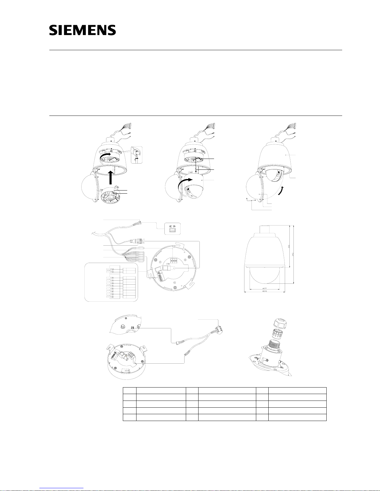
1 Dome base 6 Dome cover 11 Video cable
2 Hook 7 Safety screws 12 Power-in cables
3 Support wire 8 Safety screwdriver 13 Communication cables
4 Dome drive 9 Unit housing
5 Sun shield 10 Power cable
Page 2
Issued by
Siemens Building Technologies
Fire & Security Products GmbH & Co. oHG
D-76181 Karlsruhe
www.sbt.siemens.com
© 2006 Copyright by
Siemens Building Technologies AG
Data and design subject to change without notice.
Supply subject to availability.
Printed in the Federal Republic of Germany
on environment-friendly chlorine-free paper.
Document no. A24205-A336-B282
Edition 09.2006
English
Safety
Target group
This installation guide is only intended for use
by installers who have an adequate working
knowledge of video systems!
General safety precautions
This guide outlines the most important
information about the housing. It is, however,
vital that you also refer to the full operating
instructions.
Scope of delivery
• Outdoor housing
• Safety screwdriver
• Gland with two-entry rubber
• Additional one-entry & four-entry rubbers
• Y cable
• Sealed pins
Installation
Installing dome in housing
A) Without PG gland
Wall mount including junction box
1. Attach the video cable (11) (included with
the dome housing) to the video connector
on the dome base (1).
2. Connect the communication cables (13)
directly to the appropriate terminals
(indicated by colour) on the dome base
(see Fig. D).
3. Connect the power-in cables (12) directly
to the termination of power on the dome
base (see Fig. D).
4. Tighten the fixing screw to fix the speed
dome base into the housing (see Fig. A
magnifying picture).
5. Connect the support wire (3) to the hook
(2) of the dome base (see Fig. A).
6. To lock the dome drive (4) to the dome
base, line up the notch with the label and
turn to the right with both hands
(see Fig. B).
7. Holding the dome casing (6) to maintain
the matched position, tighten the 3
screws (7) with a screwdriver (8) and lock
the dome cover to the unit housing (9)
(see Fig. C).
8. The installation is now completed.
B) With PG gland
Simple wall and pendant mount
1. Separate the sealing nut & two-entry
rubber from the outdoor housing (Fig. G),
and then take out the speed dome cables
(see Fig. D: 10, 11, 12, 13) from the
outdoor housing.
2. Connect the Y cable (the ends with
contact shoes) to the power terminal; the
other end is for the heater connector (see
Fig. F).
3. Replace the two-entry rubber with the
four-entry/one-entry rubber based on the
wiring (see Fig. G).
NOTE:
We recommend to use a PG gland for all
kinds of mounts to ensure improved IP66 of
the housing.
Connect the lines from the field to the power
terminal, BNC connector, Alarm IN/Out &
Data at the dome, pulling the cable through
the one-/four-entry rubber.
4. Screw on the sealing nut.
5. Make sure that the gland is fixed properly
to keep humidity out of the housing and
ensure IP66.
Operation and storage
Do not operate or store the unit :
• At extremely hot or cold places.
• Close to sources of strong magnetism.
• Close to sources of powerful
electromagnetic radiation such as radios
or TV transmitters.
• Where exposed to mechanical vibrations.
• Close to fluorescent lamps or objects
reflecting light.
• Under unstable or flickering light sources.
Technical data
Height 345 mm
Diameter 240 mm
Weight 4.0 kg (max.)
Bubble clear
Operating temperature -30 – +50 °C
Storage temperature -40 – +60 °C
Relative humidity 0 – 90%
Heater switch temperature On: +4 °C
Off: +16 °C
Heater: 24 VA
Input voltage 24 V AC
Power consumption 26 VA
housing only
Protection type IP66
Bubble impact resistance 800 kg
CAUTION
1. Ensure that the safety wire (located in the dome base) is engaged.
2. Align notch with "OPEN" arrow and turn dome until notch meets arrow in "LOCKED" position.
3. When using outdoor housing, ensure that safety-wire of dome housing is always fixed firmly to the
mount to prevent unit from falling down.
4. Check assembly by pulling. Assembly should not come apart.
English
For more detailed information please refer to the Instruction Manual for ¼" Speed Dome Cameras.
Deutsch
Nähere Informationen hierzu finden Sie im Installationshandbuch für ¼" Speed Dome Cameras.
Français
Veuillez consultez le guide d'opération des cameras ¼" Speed Dome pour d’information plus détaillée.
Nederlands
Uitgebreide Informatie find u in het instruktie handboek voor ¼ Speed Dome Kameras.
Italiano
Per maggiori dettagli si rimanda al manuale specifico di istruzione della telecamera Speed Dome ¼".
Polski
Więcej informacji zawiera instrukcja obsługi zintegrowanej kamery szybkoobrotowej ¼”.
Svenska
För ytterligare information hänvisas till installationsmanualen för ¼" Speed Dome Cameras.
Español
Por favor, para una información más detallada, consulte con el manual de instrucciones de los domos
de alta velocidad de ¼”.
Portugues
Ou uma informação mais detalhada consulta por favor ao Manual do utilizador Câmaras de Tecto de
Alta Velocidade ¼ polegada.
Česky
Pro podrobnější informace se prosím podívejte do návodu pro obsluhu ¼" Speed Dome kamery.
 Loading...