

Page 1
Configuring the HMI device
REVIEW ENGLISH
27.07.2010
6.12 Changing Internet settings
6.12 Changing Internet settings
6.12.1 Changing general settings
You can use this function to set the homepage and search engine page for an Internet
connection via the Internet Explorer. Ask your network administrator for the required
information.
Requirement
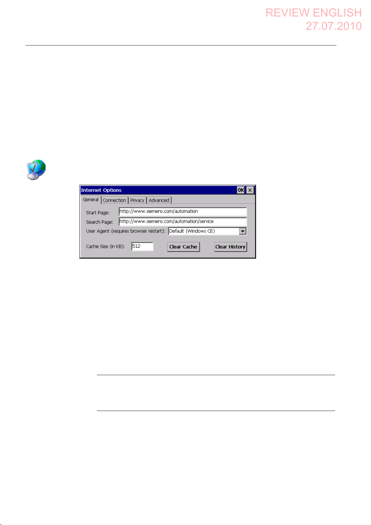
You have opened the "General" tab in the "Internet Options" dialog box using the
"Internet Options" icon.
Procedure
Proceed as follows:
1. Enter the homepage for the Internet browser in the "Start Page" text box.
2. Enter the address of the default search engine in the "Search Page" text box.
3. Enter the display format of the Internet pages in the "User Agent" text box.
The following display formats can be selected:
– Default (Windows CE)
– Same as Pocket PC
– Same as Windows XP
Note
The "Default (Windows CE)" display format is optimized for Internet pages on a HMI
device with the Windows CE operating system. "Default (Windows CE)" is therefore
the most suitable.
4. Enter the required amount of cache in the "Cache" text box.
5. If you want to delete the cache, press the "Clear Cache" button.
Mobile Panel 277F IWLAN V2, Mobile Panel 277F IWLAN (RFID Tag)
180 Operating Instructions, 09/2010, A5E02766325-01
Page 2
Configuring the HMI device
REVIEW ENGLISH
27.07.2010
6.12 Changing Internet settings
6. If you want to delete the history, press the "Clear History" button.
7. Confirm your entries.
The dialog closes.
Result
The general parameters for the Internet browser have been set. The settings take effect the
next time you start the Internet Explorer.
6.12.2 Setting the proxy server
Use this function to configure the type of Internet access. Ask your network administrator for
the required information.
Requirement
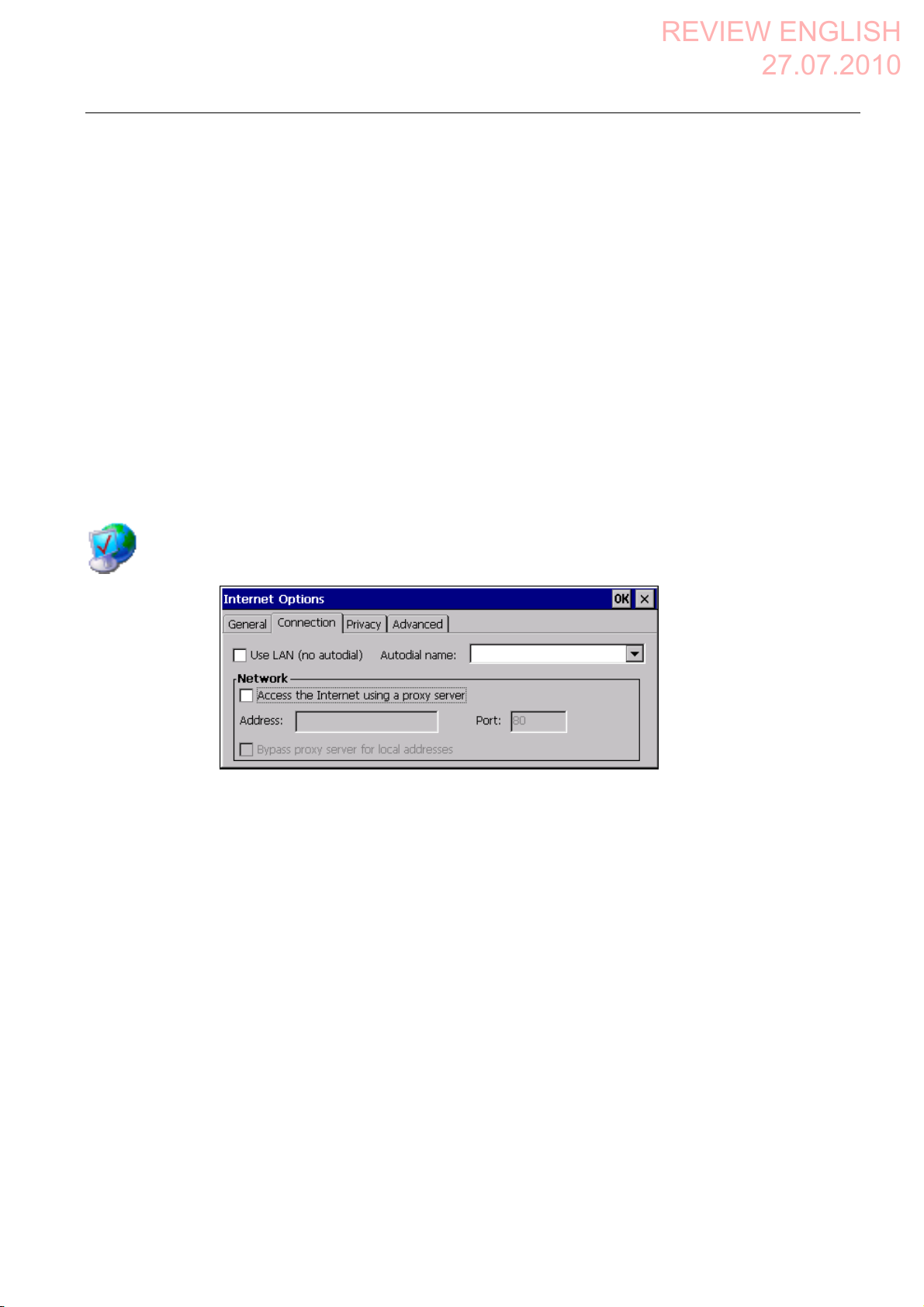
You have opened the "Connection" tab in the "Internet Options" dialog box using the
"Internet Options" icon.
Procedure
Proceed as follows:
1. Select the "Use LAN (no autodial)" check box.
2. If you are using a proxy server, in the "Network" group, select the
"Access the Internet using a proxy server" check box.
Specify the address and port of the proxy server.
3. If you want to bypass the proxy server for local addresses, select the
"Bypass proxy server for local addresses" check box.
4. Confirm your entries.
The dialog closes.
Result
The parameters for the LAN connection have been made.
Mobile Panel 277F IWLAN V2, Mobile Panel 277F IWLAN (RFID Tag)
Operating Instructions, 09/2010, A5E02766325-01
181
Page 3

Configuring the HMI device
REVIEW ENGLISH
27.07.2010
6.12 Changing Internet settings
6.12.3 Changing privacy settings
Cookies contain information sent by a Web server to a browser. The cookie is sent back
when the Web server is accessed at a later time. This step involves sending stored
information for subsequent access.
Data can be sent encrypted for greater data security on the Internet. Common encryption
protocols include SSL and TLS. You can activate or deactivate the usage of encryption
protocols.
Ask your network administrator for the required information.
Requirement
You have opened the "Privacy" tab in the "Internet Options" dialog box using the
"Internet Options" icon.
Procedure
Proceed as follows:
1. Select the required cookie behavior by means of the radio buttons.
– "Accept"
Cookies are stored without request.
– "Block"
Cookies will not be stored.
– "Prompt"
Cookies will be stored on request.
2. If you want allow cookies which are restricted to a single session, select the
"Always allow session cookies" check box.
Mobile Panel 277F IWLAN V2, Mobile Panel 277F IWLAN (RFID Tag)
182 Operating Instructions, 09/2010, A5E02766325-01
Page 4
Configuring the HMI device
REVIEW ENGLISH
27.07.2010
6.12 Changing Internet settings
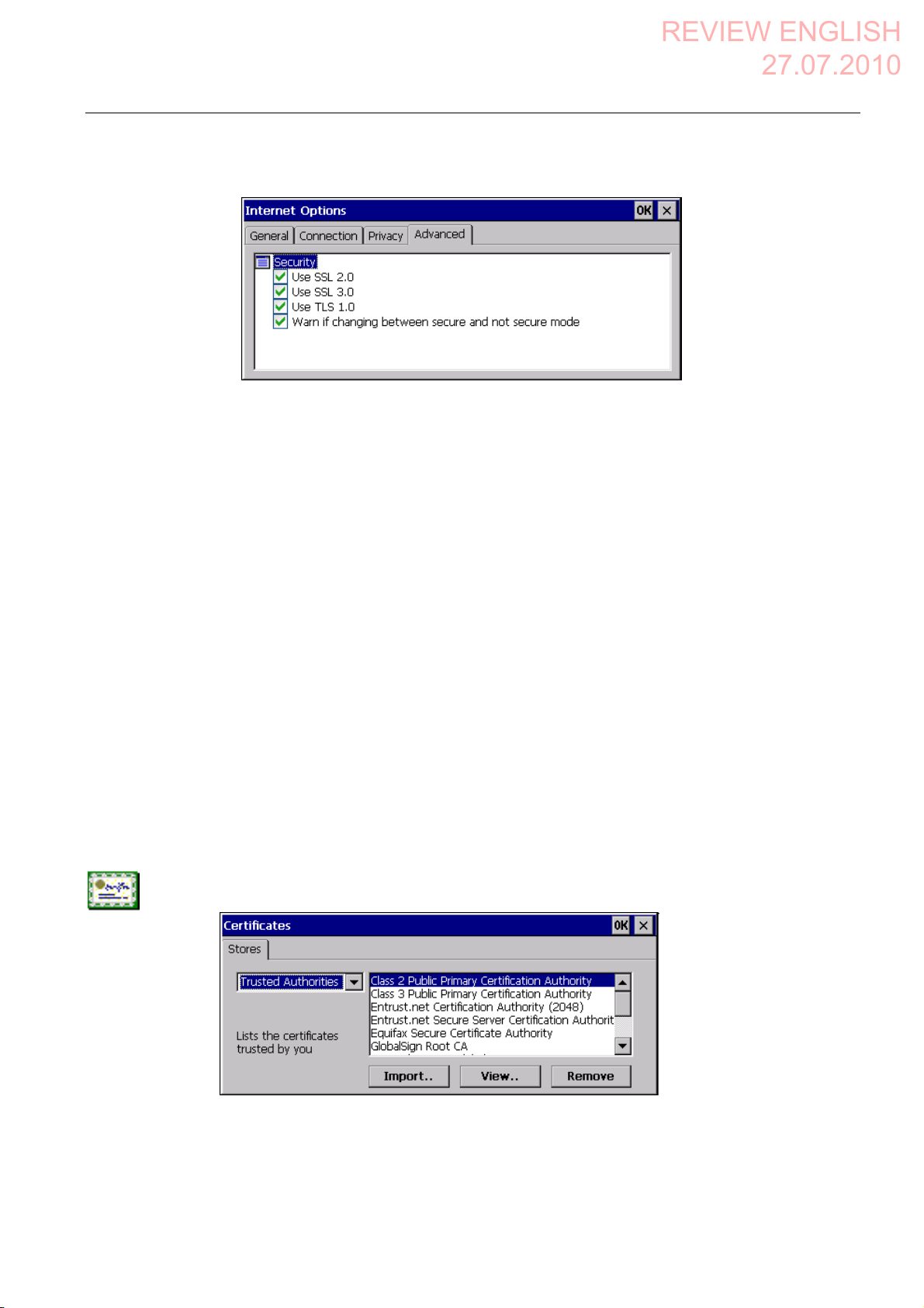
3. Change to the "Advanced" tab.
4. Activate the required encryption protocol.
5. Confirm your entries.
The dialog closes.
Result
The accepted cookies and the required encryption protocol are set.
6.12.4 Importing, displaying and deleting certificates
You can use this function to import, display and delete certificates. The certificates differ as
follows:
● Certificates that you trust
● Own certificates
● Other certificates
A digital certificate consists of structured data, which confirms ownership and other
properties of a public key. Ask your network administrator about the certificates required for
your application.
Requirement
You have opened the "Certificates" dialog box with the "Certificates" icon.
Mobile Panel 277F IWLAN V2, Mobile Panel 277F IWLAN (RFID Tag)
Operating Instructions, 09/2010, A5E02766325-01
183
Page 5
Configuring the HMI device
REVIEW ENGLISH
27.07.2010
6.12 Changing Internet settings
Procedure
Proceed as follows:
1. Select the type of certificate from the selection box:
– "Trusted Authorities" for reliable certificates
– "My Certificates" for your own certificates
– "Other Certificates" for other certificates
2. If you want to import a certificate, press the "Import" button.
A dialog with information about the source opens.
– Select the required source.
– Close the dialog.
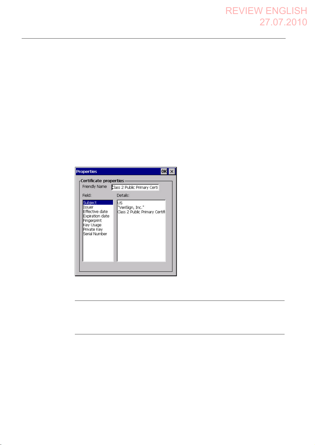
3. If you want to display the properties of the selected certificate, press the "View" button.
The following dialog appears:
4. If you want to delete a certificate, first select it.
5. Confirm by pressing the "Remove" button in the "Certificates" dialog.
Note
The entry is deleted immediately and without further inquiry.
If you want to again use a deleted certificate, you need to import it again from a storage
medium.
6. Confirm your entries.
The dialog closes.
Result
The number of saved certificates has changed.
Mobile Panel 277F IWLAN V2, Mobile Panel 277F IWLAN (RFID Tag)
184 Operating Instructions, 09/2010, A5E02766325-01
Page 6

Configuring the HMI device
REVIEW ENGLISH
27.07.2010
6.13 Saving to external storage medium – backup
6.13 Saving to external storage medium – backup
You can use this function to back up the operating system, applications and data from the
internal in flash memory of the HMI device to an external storage medium. See section
"Displaying information about the HMI device (Page 158)".
Requirement
The followi
● Memory card
● USB memory stick
● Storage medium with sufficient free capacity is inserted in the memory card slot.
See section "Inserting a memory card (Page 87)".
● Data that mig
● You have opened the "Backup/Restore" dialog box using the "Backup/Restore" icon.
ng extern
al storage media can be used:
ht be over
written are saved.
Procedure
Proceed as follows:
1. Click the "BACKUP" button.
The "Select Storage Card"" dialog box is displayed. The "--- no storage card available ---"
message appears if there is no memory card in the HMI device or it is defective. Insert a
memory card or insert another one.
2. Select the storage medium for backup from the "Please select a Storage Card" list box.
Mobile Panel 277F IWLAN V2, Mobile Panel 277F IWLAN (RFID Tag)
Operating Instructions, 09/2010, A5E02766325-01
185
Page 7

Configuring the HMI device
REVIEW ENGLISH
27.07.2010
6.14 Restoring from external storage medium – Restore
3. Click the "Start Backup" button.
The HMI device checks the storage medium.
If the "This storage card..." message appears, you need a storage medium of greater
capacity. Acknowledge this message. Backup is aborted at this point. Insert a storage
medium with a greater capacity and restart the backup process.
If the "You may have an old backup on the storage card. Do you want to delete it?"
message appears, there is already a backup on the storage medium. If you do not want
to overwrite the backup, press the ""No"" button. Otherwise, click the "Yes" button.
Several messages are displayed in sequence during the backup process:
– Saving registry data
– Copy files
A progress bar shows the status of the backup process. When the backup process is
completed, the "The operation completed successfully." message is displayed.
4. Acknowledge this message.
The dialog closes.
Result
The HMI device data is now saved on the storage medium.
6.14 Restoring from external storage medium – Restore
Use this function to restore data from a storage medium to the HMI device.
A restore operation deletes the old data from flash memory of the HMI device on
confirmation. The data stored on the storage medium is then copied to the internal flash
memory.
Mobile Panel 277F IWLAN V2, Mobile Panel 277F IWLAN (RFID Tag)
186 Operating Instructions, 09/2010, A5E02766325-01
Page 8

Configuring the HMI device
REVIEW ENGLISH
27.07.2010
6.14 Restoring from external storage medium – Restore
Requirement
● The storage medium with the backup data is inserted in the HMI device.
See section "Inserting a memory card (Page 87)".
● You have op
NOTICE
Data loss
All data on the HMI device will be deleted during a restore operation. License keys will
be deleted after query.
Back up the HMI device's data before restoring if required.
Memory card with data backup
If several storage media with data backups are inserted, the data cannot be restored.
Remove the storage medium with the data backups you do not need.
ened the "Bac
kup/Restore" dialog box using the "Backup/Restore" icon.
Mobile Panel 277F IWLAN V2, Mobile Panel 277F IWLAN (RFID Tag)
Operating Instructions, 09/2010, A5E02766325-01
187
Page 9

Configuring the HMI device
REVIEW ENGLISH
27.07.2010
6.14 Restoring from external storage medium – Restore
Procedure
Proceed as follows:
1. Click the "RESTORE" button.
The "Storage Card" dialog box opens.
① No memory card available
② Only one memory card with a backup is permitted. No memory card detected. Insert a
memory card and press the "Refresh" button.
2. Select the storage medium with the backup from the "Storage Card with Backup
detected" selection box.
The "--- no storage card available ---" message appears if there is no storage medium in
the HMI device or it is defective.
3. If the "--- no storage card available ---" message appears, press the "Cancel" button.
Restoring is then aborted.
– Insert a storage medium or another one.
– Click the "Refresh" button.
The content of the selection box changes.
– Select the storage medium with the backup from the "Storage Card with Backup
detected" selection box.
4. Click the "Start Restore" button.
Restoring is started.
5. The data to be restored is checked.
The following messages are displayed in sequence during the check.
– "Starting Restore"
– "Checking data"
When the data has been checked, the following message is displayed:
"You are starting RESTORE now. All files (except files on storage cards) and the registry
will be erased. Are you sure?"
6. If you do not want to permit that data are deleted from the HMI device, abort the restore
process by pressing the "ESC" button.
Mobile Panel 277F IWLAN V2, Mobile Panel 277F IWLAN (RFID Tag)
188 Operating Instructions, 09/2010, A5E02766325-01
Page 10

Configuring the HMI device
REVIEW ENGLISH
27.07.2010
6.15 Activate memory management
7. Start to restore the data by selecting "Yes".
The following messages are displayed in sequence during the restore:
– "Deleting files on flash"
– "Restore CE Image"
A progress bar shows the status of the restore process.
When restore is completed, the following message is displayed:
"Restore succesfully finished. Press ok, remove your storage card and reboot your
device."
8. Remove the storage medium.
9. Acknowledge this message.
The HMI device starts again.
Result
The data from the storage medium is now on the HMI device.
Note
After the restore, check whether it is necessary to calibrate the touch screen.
6.15 Activate memory management
If memory management is activated, the HMI device will automatically close the project if the
memory needs reorganizing during the active project.
If the project is closed due to this setting, then a message will be displayed on the HMI
Requirement
device. You have to start the project again.
NOTICE
Memory management
If you do not activate memory management, malfunctions can occur during the runtime of
the project.
Select memory management in the "OP Properties" dialog.
You have opened the "Memory Monitoring" tab in the "OP Properties" dialog using the
"OP" icon.
Mobile Panel 277F IWLAN V2, Mobile Panel 277F IWLAN (RFID Tag)
Operating Instructions, 09/2010, A5E02766325-01
189
Page 11

Configuring the HMI device
REVIEW ENGLISH
27.07.2010
6.15 Activate memory management
① Percent of maximum memory used since the last startup of the HMI device
② Percentage of memory currently used
③ Check box for selecting memory management
Procedure
Proceed as follows:
Result
1. If you want to enable memory management, then select the check box.
2. Confirm your entries.
The dialog closes.
Memory management is activated.
Mobile Panel 277F IWLAN V2, Mobile Panel 277F IWLAN (RFID Tag)
190 Operating Instructions, 09/2010, A5E02766325-01
Page 12

REVIEW ENGLISH
27.07.2010
Safety-related configuration
7.1 General procedure
Programs for fail-safe operation
For fail-safe operation of the HMI device, the following software is required:
● STEP 7, hardware configuration "HW Config"
● Add-on package "S7 Distributed Safety", V5.4, SP3
● WinCC flexible
See also section "Software requirements (Page 25)".
The soft
manager. You can find additional information in the Start menu.
Program Task Start menu
STEP 7, HW Config Creating a project for the
S7 Distributed Safety Create a safety program SIMATIC >
WinCC flexible Create a project for the HMI
ware is installed on
automation system
device
the configuration computer and is called through the SIMATIC
7
SIMATIC >
Documentation >
desired language
Documentation >
desired language
SIMATIC >
WinCC flexible 2007 >
WinCC flexible help system
Procedure
Proceed as follows:
1. Create a STEP 7 project in the SIMATIC Manager.
2. Configure the desired F-CPU and a PROFINET connection in the hardware configuration
"HW Config".
3. Add a mobile HMI device to the configuration from the hardware catalog of HW Config.
4. Set the parameters for the communication with the controller.
See section "Assigning parameters for communication between the HMI device and the
controller (Page
5. Config
6. Create a safety program for the F-CPU in STEP 7 with S7 Distributed Safety.
7. Insert the F-FBs required for the HMI device in the safety program.
Mobile Panel 277F IWLAN V2, Mobile Panel 277F IWLAN (RFID Tag)
Operating Instructions, 09/2010, A5E02766325-01
ure othe
Close these FBs according to the instructions. Follow the checklist for this procedure –
see section "Checklist for EMERGENCY STOP c
194)".
r components in accordance with your plant.
onfiguration (Page 197)".
191
Page 13

Safety-related configuration
REVIEW ENGLISH
27.07.2010
7.2 Checklist for configuration
8. Open the program, WinCC flexible ES.
9. Create a project for the HMI device.
10. Set "Ethernet/Wireless" in the project view under "Communication".
11. Configure the PROFIsafe address of the HMI device in the project window under "Device
Settings > Device Settings".
12. Configure the effective ranges for your plant under "Device Settings > Effective Ranges".
13. Configure the HMI screens for operator control and monitoring of the plant in fail-safe
mode.
7.2 Checklist for configuration
Perform the following tasks for safety-related configuration. Confirm each task by checking it
off in the following list.
Task Information source Check
STEP 7, HW Config
Add the HMI device to the plant configuration
Set the PROFIsafe parameters
SIMATIC STEP 7 (Page 193)
S7 Distributed Safety
Call the required F-FBs in the safety program
WinCC flexible
Configure the unique project identifiers for the
effective ranges and operator controls
Configuring the HMI device Configuring the HMI device
Using F-FBs (Page 198)
Configuration in WinCC flexible
(Page 209)
(Page 127)
Mobile Panel 277F IWLAN V2, Mobile Panel 277F IWLAN (RFID Tag)
192 Operating Instructions, 09/2010, A5E02766325-01
Page 14

Safety-related configuration
REVIEW ENGLISH
27.07.2010
7.3 SIMATIC STEP 7
7.3 SIMATIC STEP 7
7.3.1 Configuring in STEP 7
Requirement
● A STEP 7 project has been created in SIMATIC Manager.
Procedure
Proceed as follows:
1. Configure the required F-CPU and a PROFINET connection in the hardware
configuration "HW Config".
2. Add a mobile HMI device to the configuration from the hardware catalog of HW Config.
To do this, drag the HMI device onto the PROFINET connection in the station window.
3. Open the object properties of the HMI device in the shortcut menu and set the
parameters for the communication to the controller.
NOTICE
Response time for the logon sequence a maximum of 2 seconds
The response time for the logon sequence may be a maximum of 2 seconds
Consider this during configuration. The response time is calculated as follows:
2 x PROFINET cycle time + maximum cycle time of the OB.
If the HMI device is not listed in the hardware catalog of HW Config, you need to integrate
the official GSD file (device database) for the HMI device in the STEP 7 database.
You can find the GSDML file on the data medium included in the scope of delivery or by
contacting your Siemens representative in the Internet
(http://support.automation.siemens.com/
WW/llisapi.dll?aktprim=99&lang=en&referer=%2f
WW%2f&func=cslib.csinfo2&siteid=csius&extranet=standard&viewreg=WW).
Note
The supplied GSD files have integrated themselves into STEP 7 during installation of
WinCC flexible.
Mobile Panel 277F IWLAN V2, Mobile Panel 277F IWLAN (RFID Tag)
Operating Instructions, 09/2010, A5E02766325-01
193
 Loading...