

Page 1
Configuring the operating system
6.10 Enabling PROFINET IO
Procedure
Proceed as follows:
1. If you wish the HMI device to load the PROFIsafe address set in the Control Panel, enter
a value between 1 and 65,534 in the "Address:" text box.
2. If you wish the HMI device to load the PROFIsafe address set in the project, enter a value
between the invalid PROFIsafe address 65,535 in the "Address:" text box.
Result
The PROFIsafe address is set.
6.10 Enabling PROFINET IO
PROFINET IO
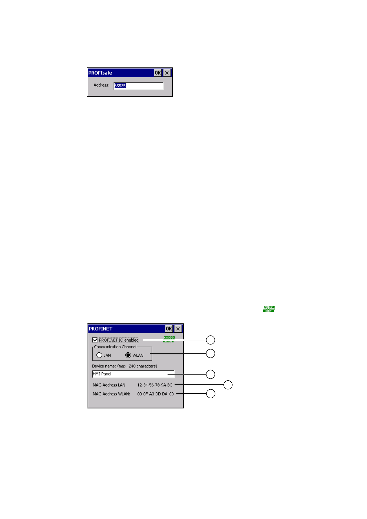
Function keys or buttons can be configured as PROFINET IO direct keys. If PROFINET IO
direct keys are used in the project, they must be enabled.
Requirements
You have opened the "PROFINET" dialog with the "PROFINET" icon.
① Check box to enable or block PROFINET IO direct keys
② Group for communications link
③ Text box for the device name
Mobile Panel 277F IWLAN
Operating Instructions, 12/2007, A5E01003940-01
165
Page 2

Configuring the operating system
6.10 Enabling PROFINET IO
④ MAC address of the LAN interface
⑤ MAC address of the WLAN interface
Procedure
1. To enable PROFINET IO direct keys, select the "PROFINET IO enabled" check box.
2. Select the communications link.
Note
Select "LAN" for service purposes only. If you select "LAN", the HMI device is connected
directly to the network via the RJ45 interface.
If you connect the configuring PC directly to the HMI device through the RJ45 interface,
you must open the connection compartment. If the connection bay is open, degree of
protection IP 65 is not fulfilled.
1. Enter the device name of the HMI device.
The device name can have a maximum of 240 characters.
NOTICE
Addressing error of PROFINET IO device
The device name does not correspond to the computer name in Windows CE.
The device name must match the device name entered in the HW Config of STEP 7.
1. Confirm your entries.
The dialog closes.
2. Reboot the HMI device after saving the settings.
Result
The PROFINET IO direct keys are enabled.
See also
Restarting the HMI device (Page 156)
Direct keys (Page 234)
Required properties of the WLAN connection (Page 57)
Mobile Panel 277F IWLAN
166 Operating Instructions, 12/2007, A5E01003940-01
Page 3

Configuring the operating system
6.11 Configuring network operation
6.11 Configuring network operation
6.11.1 Overview of network operation
Introduction
You connect the HMI device to a PROFINET network.
The connection to a network offers, for example, the following options:
● Printing via a network printer
● Saving, exporting and importing of recipe data records on or from a server
● Setting up of message and data archives
● Transferring a project
Addressing
● Saving data
NOTICE
The HMI device can only be used in PROFINET networks.
The HMI device only has client functionality in the PC network. This means that users
can access files of a node with TCP/IP server functionality from the HMI device via the
network. However, you cannot, for example, access data on the HMI device from a PC
via the network.
Note
Information on communication using SIMATIC S7 via PROFINET is provided in the
"WinCC flexible communication" user manual.
Within a PROFINET network, computers are usually addressed using device names. These
device names are translated from a DNS or WINS server to TCP/IP addresses.
The corresponding servers are generally available in PROFINET networks.
Note
The use of TCP/IP addresses to address PCs is not supported by the HMI device's operating
system.
So to address the HMI device using device names in a PROFINET network, you need a
DNS or WINS server.
Consult your network administrator if you have questions in this regard
Mobile Panel 277F IWLAN
Operating Instructions, 12/2007, A5E01003940-01
167
Page 4

Configuring the operating system
6.11 Configuring network operation
Printing via a network printer
The HMI device's operating system does not support line by line alarm logging via a network
printer. All other printing functions, for example hardcopy or logs are available without
restriction via the network.
Preparation
Before beginning the configuration, request the following network parameters from your
network administrator.
● Does the network use DHCP for dynamic assignment of network addresses?
If not, get a new TCP/IP network address for the HMI device.
● Which TCP/IP address does the default gateway have?
● If a DNS network is used, what are the addresses of the name server?
● If a WINS network is used, what are the addresses of the name server?
General procedure for configuring the network
The HMI device must be configured prior to network operation. The configuration is basically
divided into the following steps:
Proceed as follows:
1. Enter the device name of the HMI device.
2. Configure the network address.
3. Set the logon information.
4. Save the settings.
6.11.2 Setting the device name of the HMI device
Introduction
The HMI device uses the device name to identify itself in the network.
Requirements
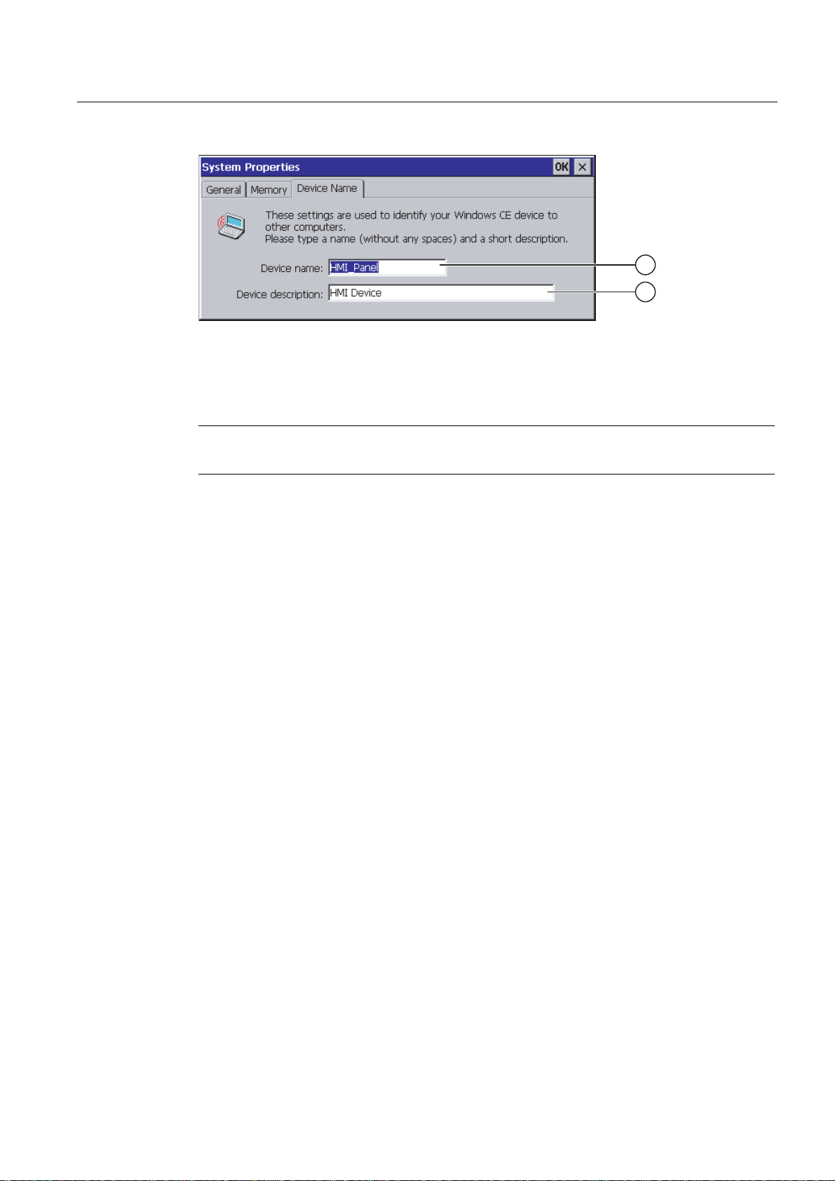
You have opened the "System Properties" dialog with the "System" icon.
Mobile Panel 277F IWLAN
168 Operating Instructions, 12/2007, A5E01003940-01
Page 5
Configuring the operating system
6.11 Configuring network operation
① Device name of the HMI device
② Description for the HMI device (optional)
Procedure
Result
See also
Note
To activate the network functions, enter a unique device name in the Device name text box.
Proceed as follows:
1. Enter the device name for the HMI device in the "Device name:" text box.
2. If necessary, enter a description for the HMI device in the "Device description:" text box.
3. Confirm your entries.
The dialog closes.
The device name for the HMI device is now set.
Overview of network operation (Page 167)
6.11.3 Changing the network configuration
Introduction
You can change the network settings for the WLAN and LAN connection under "Network and
Dial-Up Connections".
Mobile Panel 277F IWLAN
Operating Instructions, 12/2007, A5E01003940-01
169
Page 6
Configuring the operating system
6.11 Configuring network operation
Requirements for changing WLAN or LAN connection settings
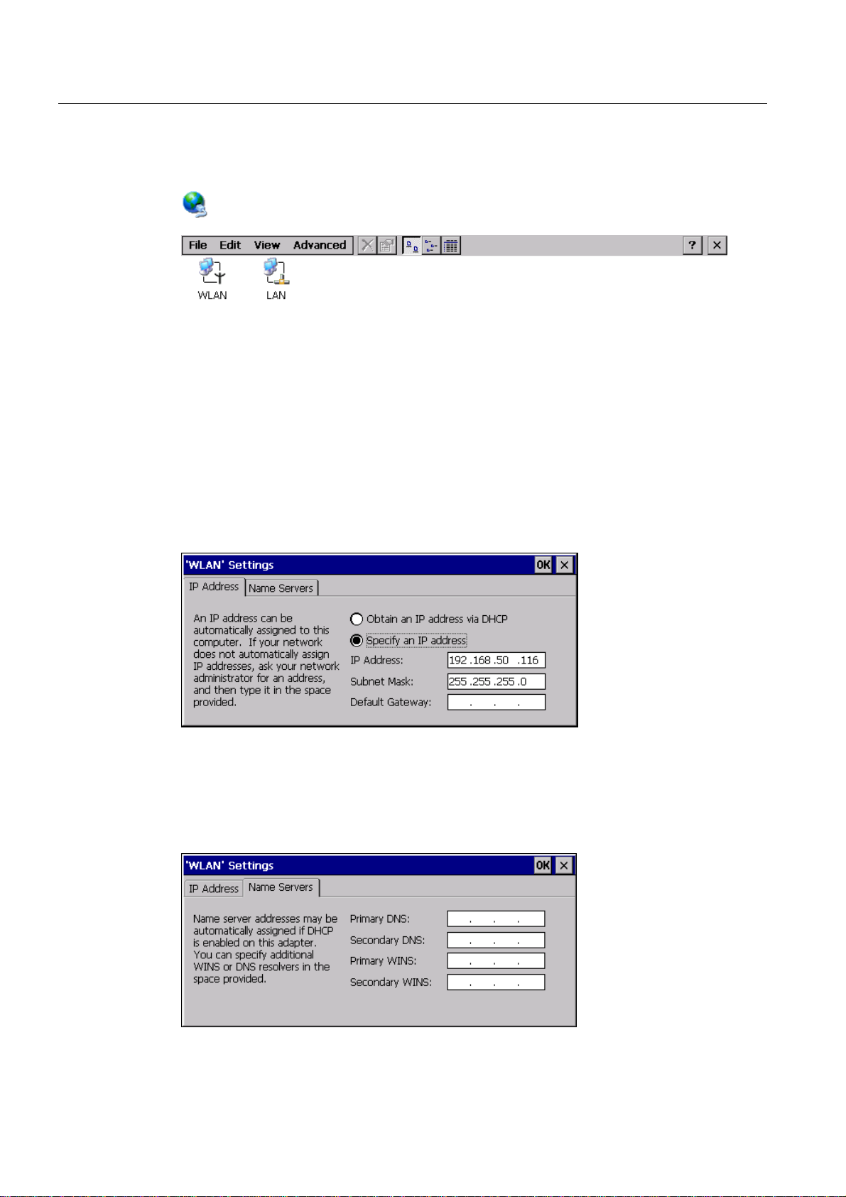
You have opened the following display by touching the "Network and Dial-Up Connections"
icon.
You can enter the connection parameters for the WLAN and LAN connection. The
parameterization is identical.
Procedure for setting the connection parameters
The following procedure shows how to set the connection parameters using the WLAN
connection.
Proceed as follows:
1. Open the "WLAN" entry.
– The "''WLAN' Settings" dialog box opens.
1. Select either automatic address assignment via DHCP or manual address assignment.
2. If you assign the address manually, enter the corresponding addresses in the text boxes
for "IP Address", "Subnet Mask" and, if used, "Default Gateway".
3. If a name server is used in the network, change to the "Name Servers" tab.
Mobile Panel 277F IWLAN
170 Operating Instructions, 12/2007, A5E01003940-01
Page 7
Configuring the operating system
6.11 Configuring network operation
1. Enter the appropriate addresses.
2. Confirm your entries.
The dialog closes.
3. Close the "Network and Dial-Up Connections" display.
The Control Panel is displayed again.
Result
The WLAN / LAN connection parameters for the HMI device have been set.
See also
Overview of network operation (Page 167)
6.11.4 Changing the logon data
Introduction
Requirements
Procedure
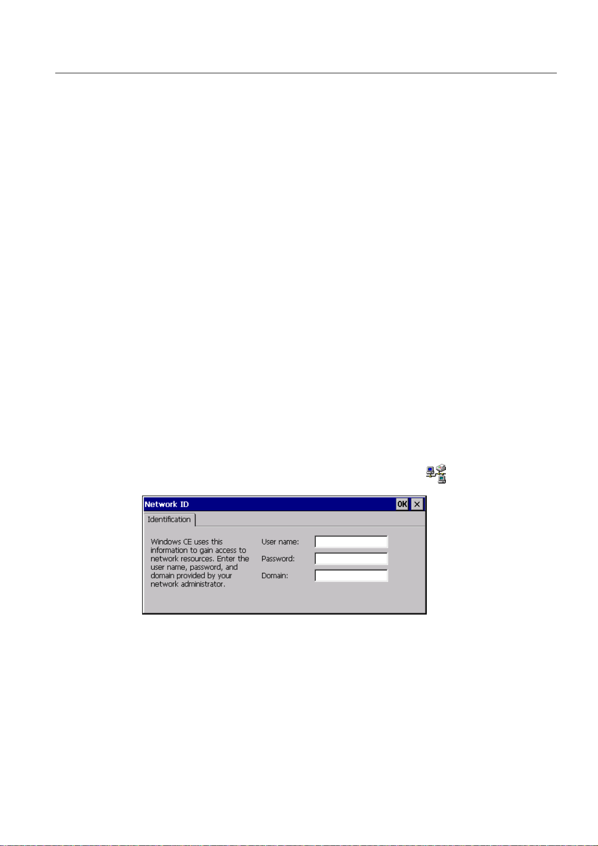
In order to access certain network resources you need to log on to the network as a user.
Your administrator will issue you with a user name and password and the name of the
domain.
You have opened the "Network ID" dialog with the "Network ID" icon.
Proceed as follows:
1. Enter the user name in the "User name" text box.
2. Enter your password in the "Password" text box.
3. Enter the domain name in the "Domain" text box.
Mobile Panel 277F IWLAN
Operating Instructions, 12/2007, A5E01003940-01
171
Page 8
Configuring the operating system
6.11 Configuring network operation
4. Confirm your entries.
The dialog closes.
Result
The logon data has now been set.
See also
Overview of network operation (Page 167)
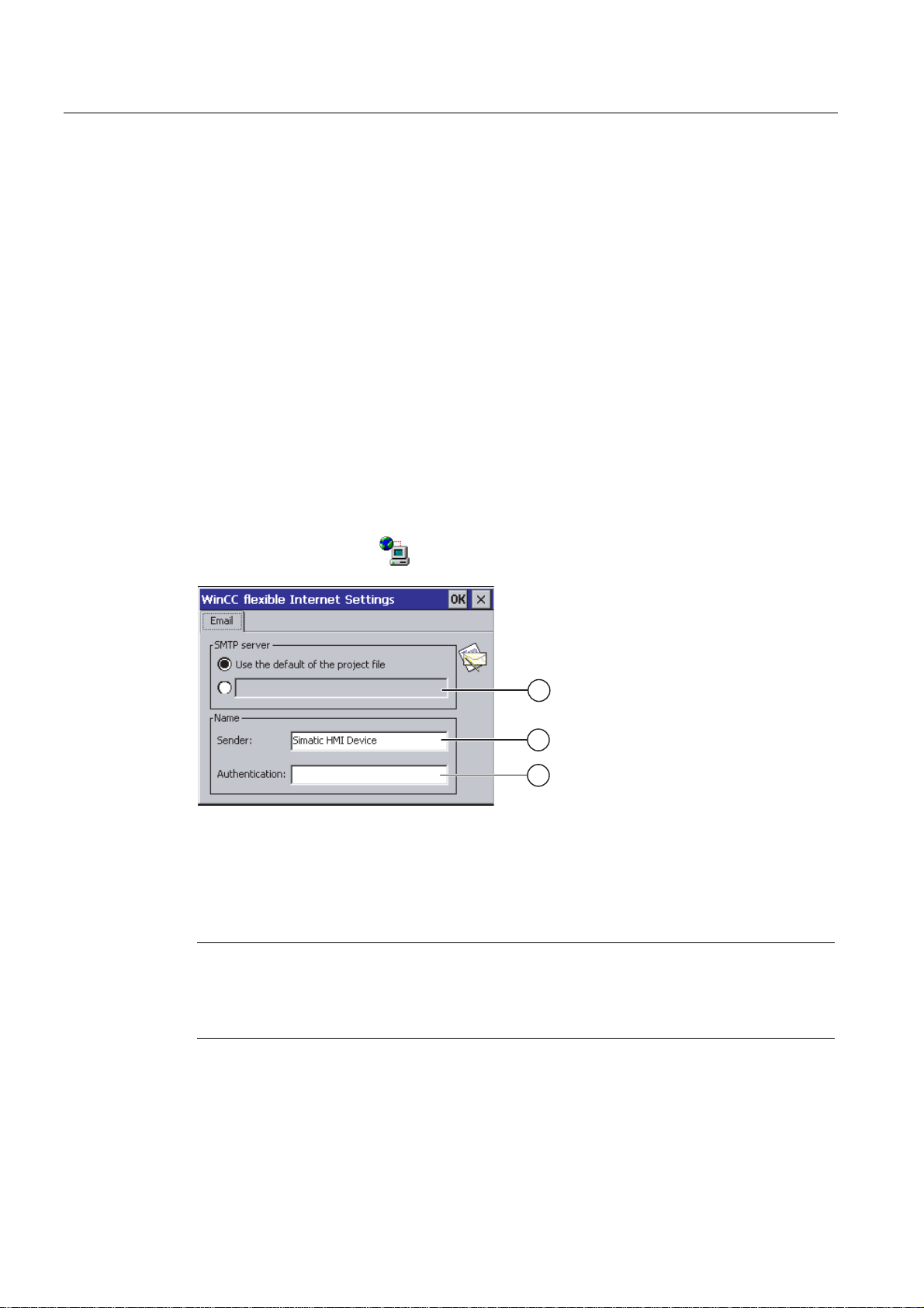
6.11.5 Changing e-mail settings
Requirements
You have opened the "WinCC flexible Internet Settings" dialog with the
"WinCC Internet Settings"
icon.
① Setting the SMTP server
② Name for the sender
③ E-mail account
Note
Options
Additional tabs may appear in the "WinCC flexible Internet Settings" dialog. This depends on
the options that have been enabled for network operation in the project.
Procedure for changing e-mail settings
Proceed as follows:
Mobile Panel 277F IWLAN
172 Operating Instructions, 12/2007, A5E01003940-01
Page 9
Configuring the operating system
6.12 Changing internet settings
1. Specify the SMTP server.
– Select the "Use the default of the project file" option button if you want to use the
SMTP server configured in the project.
– Clear the "Use the default of the project file" option button if you do not want to use the
SMTP server configured in the project. Specify the required SMTP server.
2. Enter the name for the sender in the "Sender" text box.
3. Enter the e-mail account for your e-mail in the "Authentication:" text box.
Some e-mail providers only allow you to send mail if you specify the e-mail account. The
"Authentication:" text box can remain empty if your e-mail provider allows you to send
mail without checking the account.
4. Confirm your entries.
The dialog closes.
Result
The e-mail settings have been changed.
See also
Overview of network operation (Page 167)
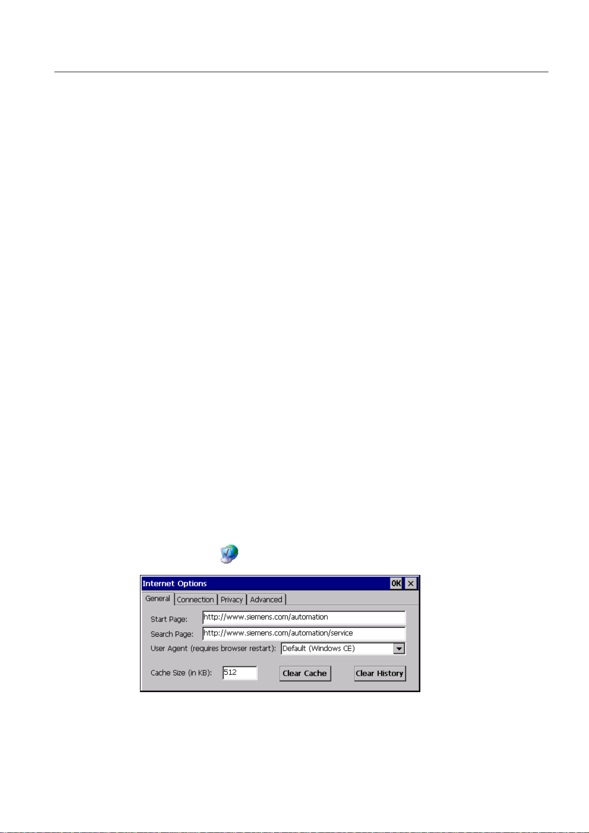
6.12 Changing internet settings
6.12.1 Changing internet settings
Requirements
You have opened the "Internet Options" dialog box, "General" tab, by touching the
"Internet Options"
icon.
Mobile Panel 277F IWLAN
Operating Instructions, 12/2007, A5E01003940-01
173
Page 10

Configuring the operating system
6.12 Changing internet settings
Procedure
Result
Note
Do not change the settings in the "User Agent" box.
Proceed as follows:
1. Enter the homepage for the Internet browser in the "Start Page" text box.
2. Enter the address of the required search engine in the "Search Page" text box.
3. Enter the required cache memory size in the "Cache" text box.
4. If you want to delete the cache memory, press the "Clear Cache" button.
5. If you want to delete the history, press the "Clear History" button.
6. Confirm your entries.
The dialog closes.
The general parameters for the Internet browser have been set.
6.12.2 Setting the proxy server
Requirements
You have opened the "Internet Options" dialog box, "Connection" tab, by touching the
"Internet Options"
Procedure
Proceed as follows:
1. Select the "Use LAN (no autodial)" check box.
icon.
Mobile Panel 277F IWLAN
174 Operating Instructions, 12/2007, A5E01003940-01
Page 11
Configuring the operating system
6.12 Changing internet settings
2. If you are using a proxy server, in the "Network" group, select the
"Access the Internet using a proxy server" check box.
Specify the address of the proxy server and the interface.
3. If you want to bypass the proxy server for local addresses, select the
"Bypass proxy server for local addresses" check box.
4. Confirm your entries.
The dialog closes.
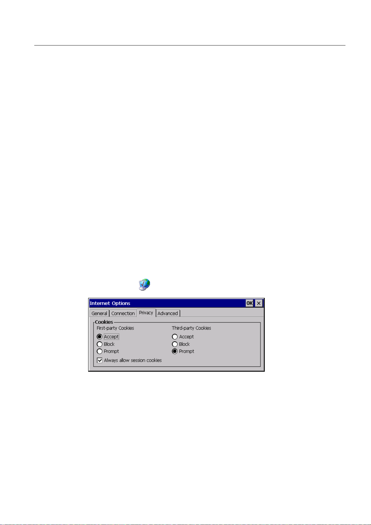
6.12.3 Changing data protection settings
Cookies and encryption
Cookies are pieces of information sent by a web server to a browser. In the event of
subsequent access to the web server, the cookies are sent back. This enables information to
be stored between the accesses.
In order to ensure a high level of privacy, data are sent via the Internet in encrypted form.
Common encryption protocols include SSL and TLS. You can activate or deactivate the
usage of encryption protocols.
Requirements
Procedure
The required settings can be obtained from your network administrator.
You have opened the "Internet Options" dialog box, "Privacy" tab, by touching the
"Internet Options"
Proceed as follows:
1. Select the required cookie behavior by means of the radio buttons.
icon.
– "Accept"
Cookies are stored without request.
– "Block"
Mobile Panel 277F IWLAN
Operating Instructions, 12/2007, A5E01003940-01
175
Page 12
Configuring the operating system
6.12 Changing internet settings
Cookies will not be stored.
– "Prompt"
Cookies will be stored on request.
2. If you want allow cookies which are restricted to a single session, select the
"Always allow session cookies" check box.
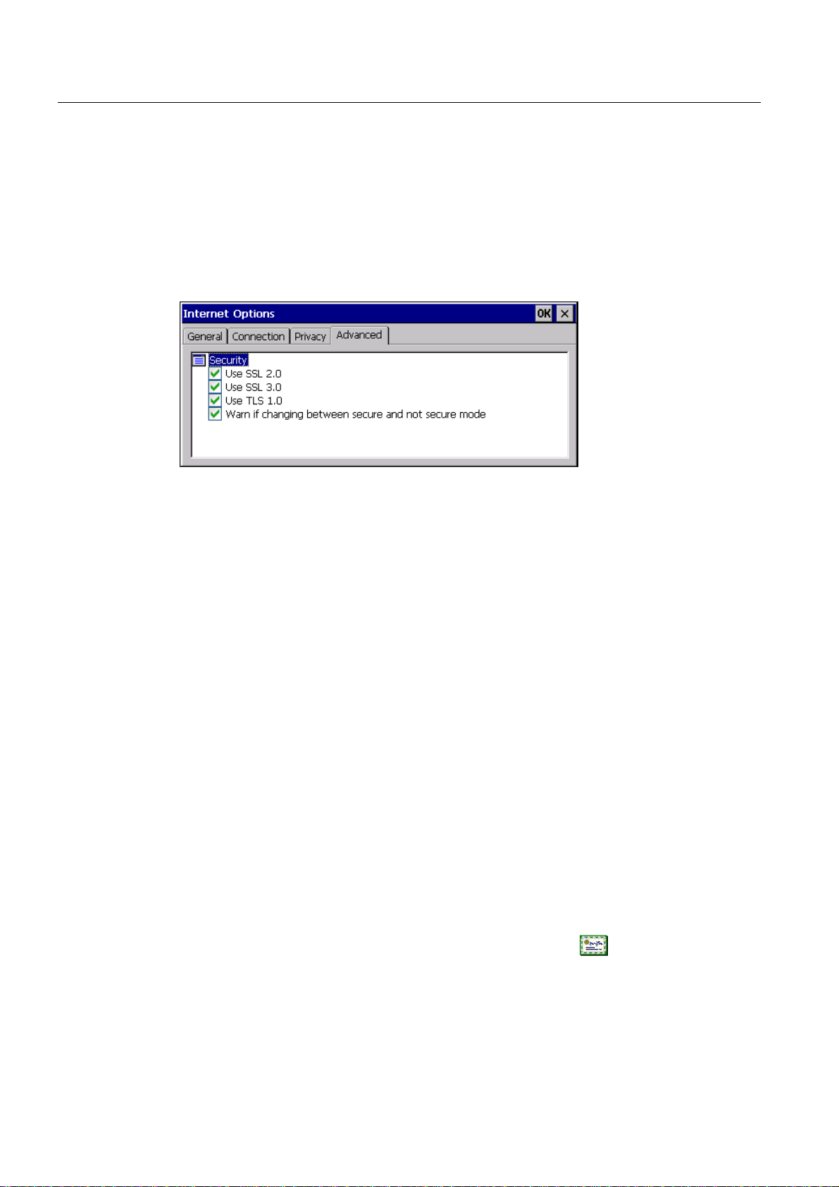
3. Change to the "Advanced" tab.
1. Activate the required encryption protocol.
2. Confirm your entries.
The dialog closes.
Result
The safety settings have now been set.
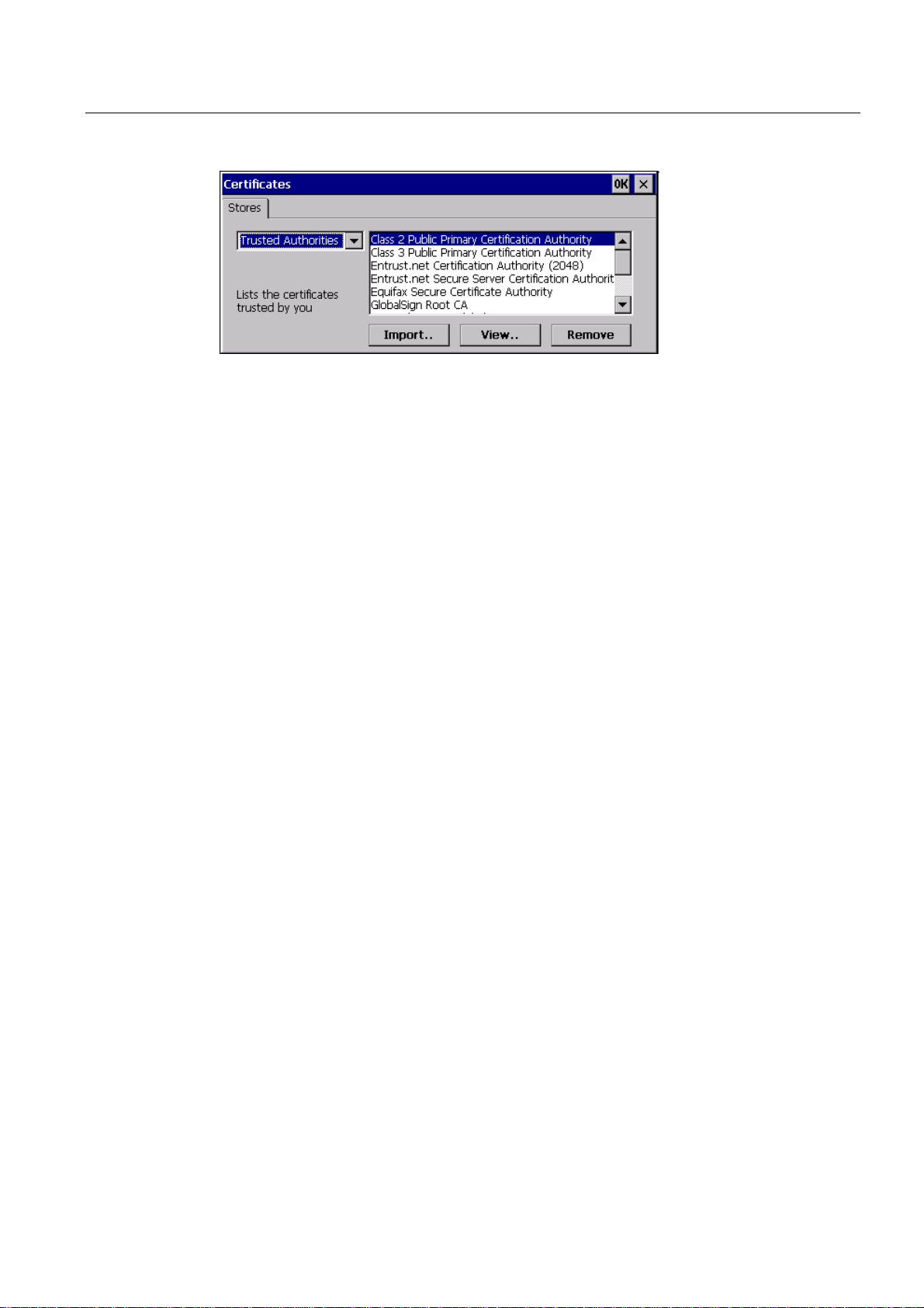
6.12.4 Importing and deleting certificates
Overview
You can import, view and delete certificates. The certificates differ in the following ways:
● Certificates that you trust
● Own certificates
● Other certificates
The required settings can be obtained from your network administrator.
Requirements
You have opened the "Certificates" dialog with the "Certificates" icon.
Mobile Panel 277F IWLAN
176 Operating Instructions, 12/2007, A5E01003940-01
Page 13
Configuring the operating system
6.13 Backing up and restoring with an external memory medium
Procedure
Proceed as follows:
1. Select the type of certificate from the selection box:
– "Trusted Authorities"
– "My Certificates"
– "Other Certificates"
2. If required, start the importing process with the "Import.." button.
A dialog with source details will open.
3. If required, delete the certificate.
– Mark the desired certificate.
– Delete the selected certificate using the "Remove" button.
4. The "View.." button enables you to list the properties of the selected certificate.
5. Close the dialog.
Result
The changes to the certificates have been carried out.
6.13 Backing up and restoring with an external memory medium
Backup
During a backup, the following data is copied from the HMI device's internal flash memory to
an external memory medium.
● Operating system
● Applications
● Data
The following external storage devices are possible:
Mobile Panel 277F IWLAN
Operating Instructions, 12/2007, A5E01003940-01
177
Page 14
Configuring the operating system
6.13 Backing up and restoring with an external memory medium
● Memory card
● USB memory stick
CAUTION
IP65 degree of protection not fulfilled
To insert or remove the memory card, you must open the HMI device's connection
compartment. If the connection bay is open, degree of protection IP 65 is not fulfilled.
It is preferable to back up onto a USB memory stick.
Requirements for backup
● The current project and all other applications are closed, except Control Panel.
● The HMI device features an external storage device with sufficient free space.
The size of the internal flash memory is displayed with information about the HMI device.
If the available space on the external memory medium is insufficient, a warning is
displayed and backup is aborted.
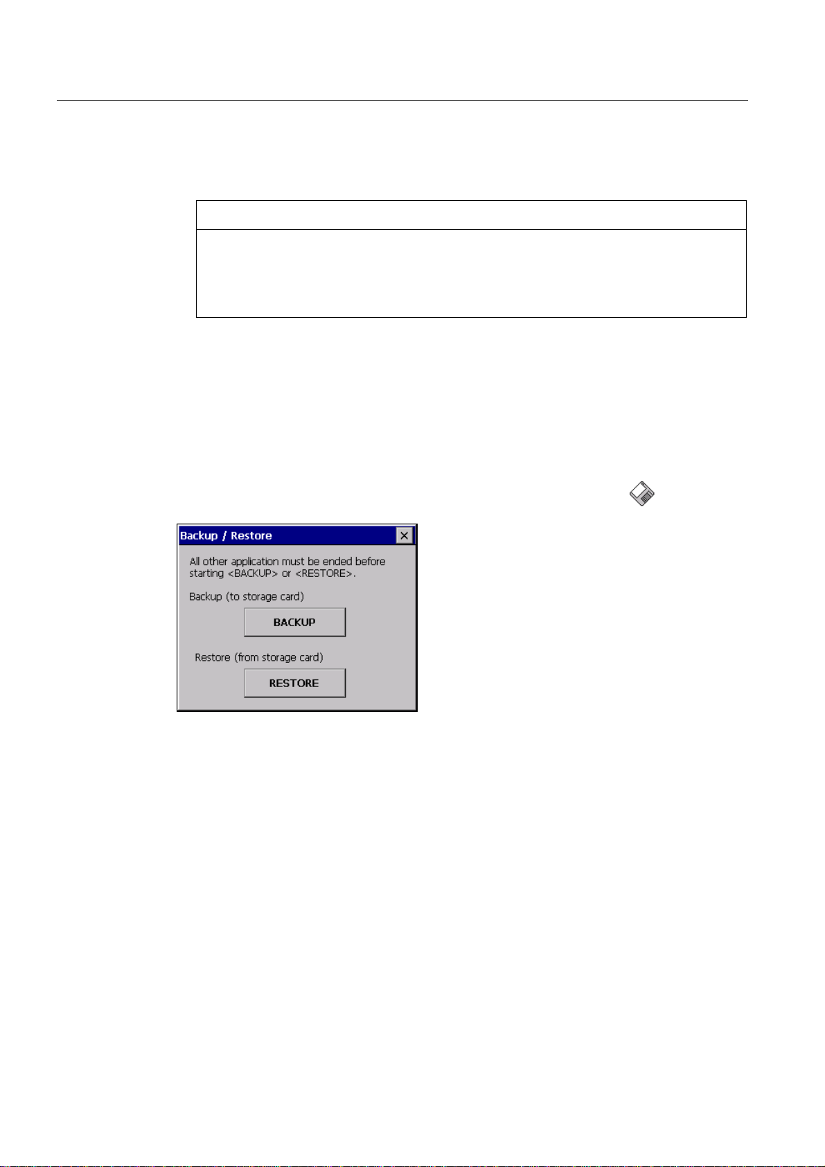
You have opened the "Backup/Restore" dialog with the "Backup/Restore"
icon.
Procedure for backup
Proceed as follows:
1. Select "BACKUP" to start Backup.
The HMI device checks the external memory.
The HMI device issues messages in the following situations:
– More than one external memory is available:
Select the desired memory.
– The external memory is not available or is defective:
Acknowledge the displayed messages.
The Control Panel is displayed again.
Replace the external memory. Start the backup process again.
Mobile Panel 277F IWLAN
178 Operating Instructions, 12/2007, A5E01003940-01
Page 15

Configuring the operating system
6.13 Backing up and restoring with an external memory medium
– Data is already stored on the external memory.
2. Follow the instructions of the HMI device.
The following messages are displayed in sequence during backup:
– "Checking Registry"
– "Backup Progress"
– "Saving CE-Image"
A progress bar shows the status of the backup process.
If backup was successful, the following message is displayed:
"Backup successfully completed. Press OK and remove your storage card."
3. Click "OK" button to acknowledge the message.
Remove the external memory medium.
Result
The HMI device data is now saved on the external memory.
Requirements for restoring
The HMI device features an external memory medium that stores the backup.
Procedure for restoring
NOTICE
Deleting the flash memory
A restore operation deletes the old data from flash memory of the HMI device on
confirmation. The data stored on the external memory is then copied to the internal flash
memory. Existing license keys are deleted following your confirmation.
The restore process involves the following steps:
● The Windows CE image is restored.
● The HMI device starts.
● All other data is restored.
NOTICE
Cancel restore
If the external memory is removed during the restore process, the process is canceled.
Ensure that the external memory is not removed at any point during the restore process.
Proceed as follows:
1. Select "RESTORE" to start Restore.
Mobile Panel 277F IWLAN
Operating Instructions, 12/2007, A5E01003940-01
179
Page 16

Configuring the operating system
6.13 Backing up and restoring with an external memory medium
The HMI device checks the external memory.
The HMI device issues messages in the following situations:
– The external memory is not available or is defective:
Acknowledge the displayed messages.
The Control Panel is displayed again.
Replace the external memory.
– More than one external memory with valid backup is available:
Remove all external memories with backups that are not needed.
If necessary, you can check the available external memories using the "REFRESH"
button.
2. If necessary, start the restore process with the "RESTORE" button.
The data to be restored is checked.
When the check is complete, one of the following prompts is displayed:
– "You are starting RESTORE now. All files (except files on storage cards) and the
registry will be erased. Are you sure?"
Result
At this point you can cancel the restore using the "No" button to prevent the data on
the HMI device from being deleted.
– You are now starting RESTORE. All files on the panel and the licenses listed below as
well as the registry will be erased. Are you sure?
This query is displayed when license keys are available both on the HMI device and in
the backup data. If necessary, cancel the restore process with the "No" button and first
back up the HMI device's license keys. Then restart the restore process.
3. Start to restore the data by selecting "Yes".
A progress bar shows the status of the restoration of the Windows CE image.
When restore is completed, the following message is displayed:
"Restore succesfully finished. Press ok, remove your storage card and reboot your
device."
4. Remove the external memory.
5. Acknowledge this message.
The HMI device starts.
The backed-up data has been restored to the HMI device.
Note
Calibrating the touch screen
After the restore, you may have to re-calibrate the touch screen.
Mobile Panel 277F IWLAN
180 Operating Instructions, 12/2007, A5E01003940-01
Page 17
Configuring the operating system
6.14 Displaying battery status
See also
Displaying information about the HMI device (Page 157)
Using a memory card with the HMI device (Page 113)
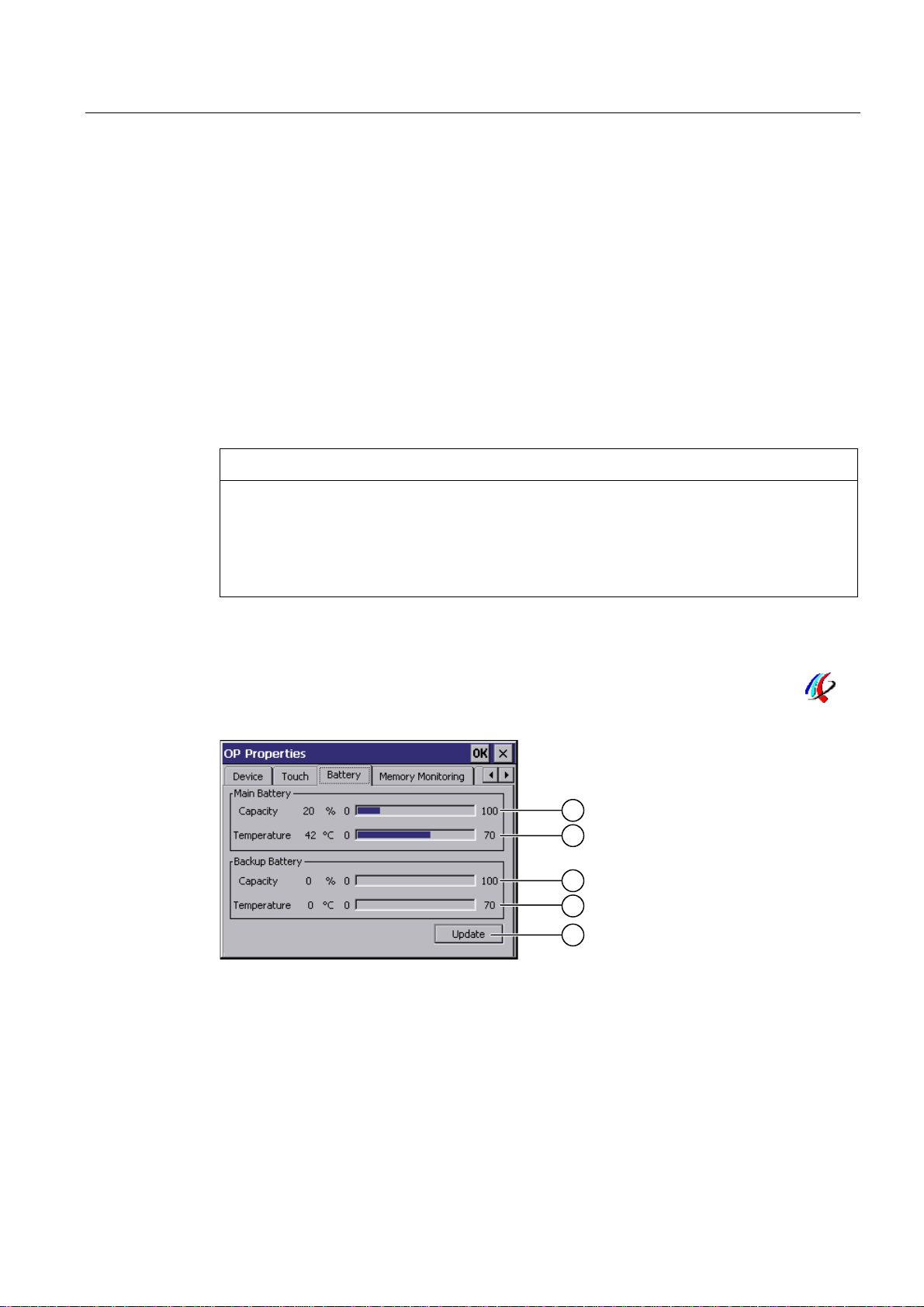
6.14 Displaying battery status
Introduction
You can check the charging status and the temperature of the main battery and the bridging
battery.
Requirements
NOTICE
Battery cannot be charged
To charge the batteries, the ambient temperature / battery temperature must not exceed
40 °C The higher the temperature, the longer it will take for the battery to charge.
Find a place with a cool ambient temperature for the charging station. If necessary, allow
the battery to cool first.
You have opened the "OP Properties" dialog box, "Battery" tab, by touching the "OP"
icon.
① Charging status of main battery
② Temperature of main battery
③ Charging status of bridging battery
④ Temperature of bridging battery
⑤ Button to update the display
Mobile Panel 277F IWLAN
Operating Instructions, 12/2007, A5E01003940-01
181
Page 18
Configuring the operating system
6.15 Activate memory management
Procedure
Proceed as follows:
1. Update the display if required by pressing the "Update" button.
2. Close the dialog.
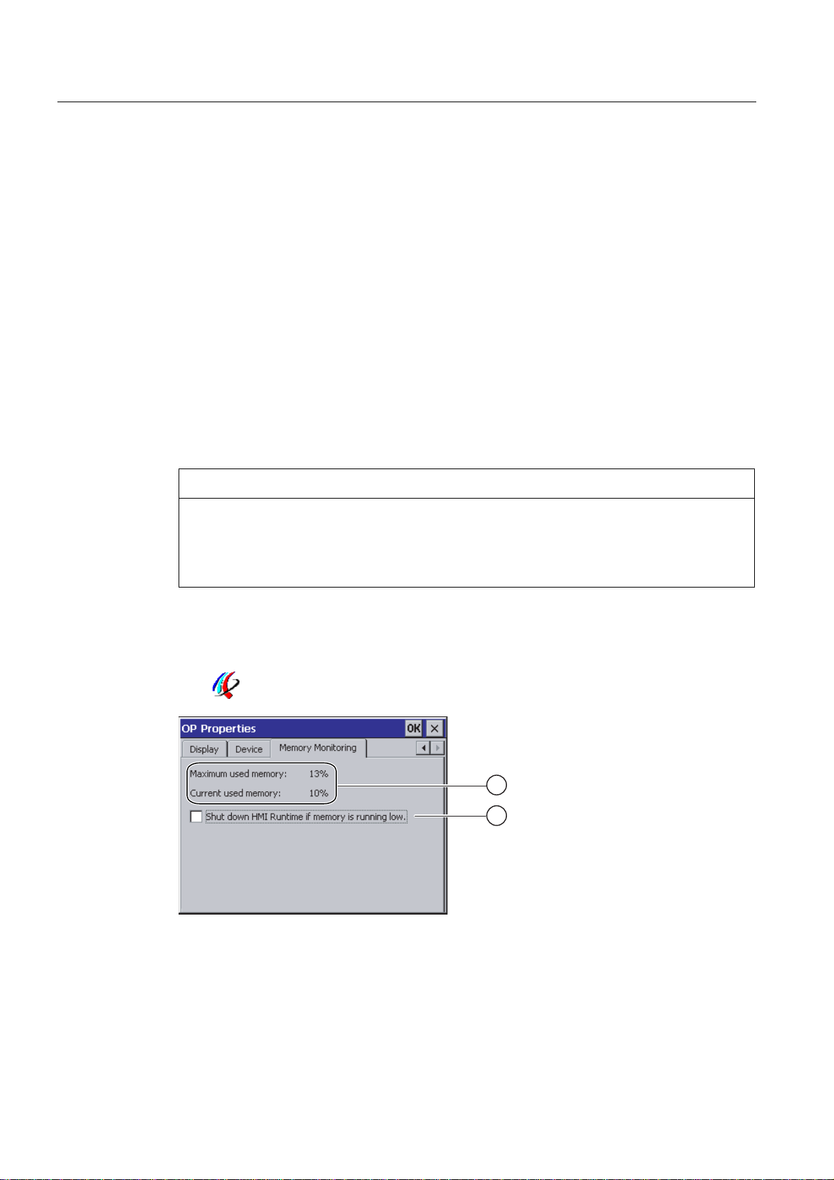
6.15 Activate memory management
Memory management
Provided the memory management is activated, the HMI device will automatically close the
project if the memory needs reorganizing during an active project.
The project is shut down and the HMI device will display a message. You have to restart the
project.
Requirements
NOTICE
Memory management
If you do not activate memory management, undefined states can occur during the runtime
of the project.
Select memory management in the "OP Properties" dialog box.
You have opened the "OP Properties" dialog box, "Memory Monitoring" tab, by touching the
"OP"
icon.
① The maximum used memory since last power on of the HMI device and the current used
memory in percent.
② Check box for selecting memory management
Mobile Panel 277F IWLAN
182 Operating Instructions, 12/2007, A5E01003940-01
Page 19

Configuring the operating system
6.15 Activate memory management
Procedure
Proceed as follows:
1. In order to start memory management, select the check box.
2. Confirm your entries.
The dialog closes.
Result
Memory management is activated.
Mobile Panel 277F IWLAN
Operating Instructions, 12/2007, A5E01003940-01
183
Page 20

Page 21

Commissioning the HMI device
7.1 Overview
Operating the HMI device
The HMI device is operated in the system as follows:
● As mobile device, with a battery
● As stationary device, in the charging station
For transfer and testing purposes, you can operate the HMI device in an office environment
as follows:
● As mobile device, with a battery
● As stationary device, with a tabletop power supply unit
● As stationary device, in the charging station
HMI device commissioning requirements
You must take the following steps before commissioning a project on the HMI device:
7
1. Install and connect up charging station
Alternatively, connect the HMI device to the tabletop power supply unit.
2. Charging the battery and inserting it in the HMI device
To charge the battery, you have the following possibilities:
– In the charging compartment of the charging station
– In the HMI device, in the charging station
– In the HMI device when connected to the tabletop power supply unit
3. Switch on the HMI device with the ON/OFF button
4. Commission and test WLAN
5. Define the settings for the transfer in the Control Panel.
6. Transfer project to the HMI device
Commissioning
Start the project once you have transferred it to the HMI device.
Mobile Panel 277F IWLAN
Operating Instructions, 12/2007, A5E01003940-01
185
Page 22

Commissioning the HMI device
7.2 Operating modes
Note
If the project contains effective ranges, you must perform an acceptance test for the effective
ranges and transponders.
You can only start the project on the HMI device once the acceptance test is complete.
● If necessary: Testing zones
See also
Mounting the charging station (Page 66)
Connection of the charging station to the power supply (Page 70)
Programming the data channel (Page 160)
Acceptance of the system (Page 196)
7.2 Operating modes
Operating modes
The HMI device may be in the following operating modes:
● Offline
● Online
● Transfer
"Offline mode" and "Online mode" can be set on both the configuring PC and the HMI
device. To set these modes on the HMI device, use a corresponding operating element of
the project.
Changing the operating mode
The configuration engineer must have configured an appropriate operating element to allow
a change of the operating mode on the HMI device during ongoing operation.
Please refer to your system documentation to check whether additional information on this
subject is available there.
"Offline" operating mode
In this operating mode, the HMI device and the PLC do not communicate via the connections
configured in the WinCC flexible project. You can operate the current project on the HMI
device, but the project data will not be transferred.
Mobile Panel 277F IWLAN
186 Operating Instructions, 12/2007, A5E01003940-01
Page 23

Commissioning the HMI device
7.3 Using existing projects
Note
Emergency stop button active
In "Offline" mode, the emergency stop button is active when the following requirements are
met:
• The HMI device is in an area with sufficient WLAN coverage.
• The HMI device is integrated in the safety program of the CPU.
"Online" operating mode
In this mode, the HMI device and PLC communicate. You can operate the plant on the HMI
device according to your system configuration.
"Transfer" mode
In this mode, you can transfer a project from the configuring PC to the HMI device or backup
and restore HMI device data, for example.
The following options are available for setting "Transfer" mode on the HMI device:
● When the HMI device starts up
Start "Transfer" mode manually in the HMI device Loader.
● During ongoing operation
Start the "Transfer" mode manually within the project using an operating element. With
automatic transfer, following a prompt the HMI device toggles to "Transfer" mode when a
transfer is initiated on the configuring PC.
7.3 Using existing projects
Note
Safety-related operator controls
The behavior and possible fields of application of the enabling button and emergency stop
button on the Mobile Panel 277F IWLAN are different from those of its predecessors, which
do not have Safety Integrated functions.
In this respect, you cannot reuse existing control programs.
For additional information on the safety-related operator controls, refer to the section titled
"Particular features of fail-safe operation" and the Function manual "Fail-safe operation of
the Mobile Panel 277F IWLAN".
You can reuse WinCC flexible projects for the following HMI devices:
● Mobile Panel 177 PN
● Mobile Panel 177 DP
Mobile Panel 277F IWLAN
Operating Instructions, 12/2007, A5E01003940-01
187
Page 24

Commissioning the HMI device
7.4 Data transmission options
● Mobile Panel 277
Carry out an HMI device switch in WinCC flexible.
Adaptations
You must adapt the following aspects of the WinCC flexible project:
● Communication via WLAN
● Zone recognition and point recognition
– If you have used point detection with box ID in an existing project, you have the
following option:
Instead of using the connection box, use a zone consisting of at least one transponder
and set the previous box ID as the ID in this zone.
– If you are using zone recognition, you will need one or more transponders for one
zone.
In WinCC flexible, you can parameterize zones in "Device settings".
You can use zones to configure an easy way of selecting a zone-specific screen.
In this case you may also need to modify the control program from previous devices.
Additional information on this subject can be found in the WinCC flexible online help or in the
"WinCC flexible migration" user manual.
7.4 Data transmission options
Overview
The following table shows the options for data transfer between Mobile Panel 277 Wireless
and a configuring PC.
The Ethernet data channel is used for communication via WLAN and LAN (RJ45).
Type Data channel Mobile Panel 277 Wireless
reset to factory settings
Installing or removing an option USB Yes
USB Yes Backup
Ethernet Yes
USB Yes Restoring
Ethernet Yes
USB Yes Updating the operating system
Ethernet Yes
USB No Updating the operating system with
Ethernet via the RJ 45
interface
USB Yes Transferring a project
Ethernet Yes
Yes
Mobile Panel 277F IWLAN
188 Operating Instructions, 12/2007, A5E01003940-01
Page 25

Commissioning the HMI device
7.5 Preparing and backing up a project
Type Data channel Mobile Panel 277 Wireless
Ethernet Yes
USB Yes License key transferring or
transferring back
Ethernet Yes
7.5 Preparing and backing up a project
7.5.1 Overview
Introduction
In order to operate the system with the HMI device, you must transfer the WinCC flexible
project to the HMI device.
Transferring the project to the HMI device
You can transfer a project to an HMI device as follows:
● Transfer from the configuring PC
● Restore from a PC using ProSave
In this case, an archived project is transferred from a PC to the HMI device.
WinCC flexible need not be installed on this PC.
Commissioning and recommissioning
● When the HMI device is commissioned there is no project at first.
The HMI device is also in this state after the operating system has been updated.
● When recommissioning, any project already on the HMI device is replaced.
See also
Operating modes (Page 186)
Mobile Panel 277F IWLAN
Operating Instructions, 12/2007, A5E01003940-01
189
Page 26

Commissioning the HMI device
7.5 Preparing and backing up a project
7.5.2 Transfer
7.5.2.1 Overview
Transfer
At the end of the configuration phase, transfer the executable project from the configuring
PC to the HMI device.
You can start the "Transfer" mode manually or automatically on the HMI device.
Transferred data is written directly to the internal flash memory on the HMI device. For the
transfer, you use a data channel which you have to configure before starting a transfer.
Backtransfer
You have the option to transfer the compressed project file together with the runtime project
to the HMI device. If necessary, the compressed project file can be transferred back to the
configuring PC and edited.
The HMI device must be equipped with an external memory to which the compressed project
file can be saved.
NOTICE
No checking of the project files
WinCC flexible does not check whether the compressed project file stored on the HMI
device corresponds to the existing runtime project.
7.5.2.2 Starting manual transfer
Introduction
You can manually switch the HMI device to "Transfer" mode as follows:
● With a configured operating element during ongoing operation
● In the Loader of the HMI device
Requirements
● The project "*.hmi" that you want to transfer is open in WinCC flexible on the configuring
PC
● The HMI device is connected to this configuring PC
● The data channel is programmed on the HMI device
● The HMI device is in "Transfer" mode
Mobile Panel 277F IWLAN
190 Operating Instructions, 12/2007, A5E01003940-01
Page 27

Commissioning the HMI device
7.5 Preparing and backing up a project
Procedure
Proceed as follows:
1. On the configuring PC, select the "Transfer settings" command in the menu "Project >
Transfer" in WinCC flexible.
The "Select devices for transfer" dialog opens.
2. Select the HMI device in the left area of the dialog.
3. Select the type of connection between the HMI device and the configuring PC.
4. Set the connection parameters.
5. Set the transfer parameters in the right area of the dialog.
6. If you wish to transfer the compressed project file together with the executable project to
the HMI device:
Select the "Enable backtransfer" check box.
7. Start transfer in WinCC flexible with "Transfer".
The configuring PC checks the connection to the HMI device. The project is transferred to
the HMI device. If the connection is not available or is defective, an error message is
displayed on the configuring PC.
Result
When the transfer is completed successfully, the project can be found on the HMI device.
The transferred project is then started automatically.
See also
Operating modes (Page 186)
Data transmission options (Page 188)
Programming the data channel (Page 160)
7.5.2.3 Starting automatic transfer
Introduction
If automatic transfer is selected, the HMI device automatically switches to "Transfer" mode
during operation as soon as a transfer is initiated on the connected configuring PC.
Note
The HMI device only switches to "Transfer" mode in the current project.
Automatic transfer is particularly suited for the test phase of a new project since transfer is
completed without interfering with the HMI device.
Mobile Panel 277F IWLAN
Operating Instructions, 12/2007, A5E01003940-01
191
Page 28

Commissioning the HMI device
7.5 Preparing and backing up a project
Requirements
NOTICE
Undesired system responses
If automatic transfer has been selected on the HMI device and a transfer is then initiated on
the configuring PC, the current project is automatically terminated following a prompt.
The HMI device then automatically switches to "Transfer" mode. The transfer mode can
trigger undesired responses in the system.
After the commissioning phase, deactivate the automatic transfer so that the HMI device
cannot be inadvertently switched to transfer mode.
You can issue a password in the Control Panel to restrict access to the transfer settings
and thus avoid unauthorized modifications.
● The project "*.hmi" that you want to transfer is open in WinCC flexible on the configuring
PC
● The HMI device is connected to this configuring PC
● The data channel is programmed on the HMI device
● The automatic transfer is activated in the data channel for the transfer
● The project is started on the HMI device
Procedure
Proceed as follows:
1. On the configuring PC, select the "Transfer settings" command in the menu "Project >
Transfer" in WinCC flexible.
The "Select devices for transfer" dialog opens.
2. Select the HMI device in the left area of the dialog.
3. Select the type of connection between the HMI device and the configuring PC.
4. Set the connection parameters.
5. Set the transfer parameters in the right area of the dialog.
6. If you wish to transfer the compressed project file together with the executable project to
the HMI device:
Select the "Enable backtransfer" check box.
7. Start transfer in WinCC flexible with "Transfer".
The configuring PC checks the connection to the HMI device.
If the HMI device is integrated, it displays the "Start removal" dialog box.
8. Press one of the enabling buttons to confirm the dialog box.
The HMI device is removed. The current project is terminated. The HMI device then
automatically switches to transfer mode. The project is transferred to the HMI device. If
Mobile Panel 277F IWLAN
192 Operating Instructions, 12/2007, A5E01003940-01
Page 29

Commissioning the HMI device
7.5 Preparing and backing up a project
the connection is not available or is defective, an error message is displayed on the
configuring PC.
Result
When the transfer is completed successfully, the project can be found on the HMI device.
The transferred project is then started automatically.
See also
Operating modes (Page 186)
Data transmission options (Page 188)
Programming the data channel (Page 160)
7.5.2.4 Starting backtransfer
Requirements
● No project is open on the configuring PC in WinCC flexible
Procedure
● The HMI device is connected to this configuring PC
● The data channel is programmed on the HMI device
● The HMI device is in "Transfer" mode
● The memory card containing the compressed project file is inserted into the HMI device
Proceed as follows:
1. On the configuring PC, select the "Communication settings" command in the menu
"Project > Transfer" in WinCC flexible.
The "Communication settings" dialog box opens.
2. Select the type of HMI device.
3. Select the type of connection between the HMI device and the configuring PC.
4. Set the connection parameters.
5. Close the dialog with "OK".
6. Select the "Transfer" > "Backtransfer" command in the "Project" menu.
The "Backtransfer" dialog opens.
7. Click "OK" to start the backtransfer process.
The configuring PC checks the connection to the HMI device. The compressed project file
is transferred back from the HMI device to the configuring PC. If the connection is not
available or is defective, an error message is displayed on the configuring PC.
Mobile Panel 277F IWLAN
Operating Instructions, 12/2007, A5E01003940-01
193
Page 30

Commissioning the HMI device
7.5 Preparing and backing up a project
Result
After successful backtransfer, the project is opened on the configuring PC in WinCC flexible.
See also
Operating modes (Page 186)
Data transmission options (Page 188)
Programming the data channel (Page 160)
7.5.3 Testing a project
Introduction
There are two options to test a project:
● Test the project on the configuring PC
You can test a project at a configuring PC, using a simulator. For detailed information,
refer to the "WinCC flexible" user manual and to the WinCC flexible online help.
● Offline testing of the project on the HMI device
Offline testing means that communication between the HMI device and PLC connections,
which have been configured in WinCC flexible, is down while the test is being carried out.
The PROFIsafe connection between the HMI device and PLC is also available in "Offline"
mode.
● Online testing of the project on the HMI device
Online testing means that the HMI device and PLC communicate with each other during
testing.
Perform the tests, starting with the "Offline test", followed by the "Online test".
Note
You should always test the project on the HMI device on which the project will be used.
Check the following:
1. WLAN coverage
2. Zone recognition, if zones have been configured
3. Check the correct layout of the screens
4. Check the screen navigation
5. Check the input objects
6. Enter the tag values
The test increases the certainty that the project will run error-free on the HMI device.
Mobile Panel 277F IWLAN
194 Operating Instructions, 12/2007, A5E01003940-01
Page 31

Commissioning the HMI device
7.5 Preparing and backing up a project
Note
Test without effective ranges
Perform the test without effective ranges.
A system acceptance test must be performed as soon as you have configured effective
ranges in your project. The effective ranges and assigned transponders will be tested as part
of the acceptance test.
Test the effective ranges separately.
Requirements for offline testing
● The project has been transferred to the HMI device
● The HMI device is in "Offline" mode.
Procedure
In "Offline" mode, you can test individual project functions on the HMI device without them
being affected by the PLC. PLC tags, therefore, are not updated.
Test the operating elements and visualization of the project as far as possible without
connecting to the PLC.
Requirements for online testing
● The project has been transferred to the HMI device
● The HMI device is in "Online" mode
Procedure
In "Online" mode, you can test individual project functions on the HMI device without them
being affected by the PLC. PLC tags are updated in this case.
You have the option to test all communication-dependent functions, for example alarms, etc.
Test the operating elements and views of the project.
See also
Acceptance of the system (Page 196)
Testing zones (Page 200)
Mobile Panel 277F IWLAN
Operating Instructions, 12/2007, A5E01003940-01
195
Page 32

Commissioning the HMI device
7.5 Preparing and backing up a project
7.5.4 Acceptance of the system
7.5.4.1 Overview
Introduction
The acceptance of the system includes the following areas:
● Configuring the F CPU and fail-safe I/O
● Safety program
● Effective ranges and transponders
Acceptance steps that you must execute in order to operate the Mobile Panel 277F IWLAN
HMI device in a system with effective ranges are described in detail in these operating
instructions.
The following manuals contain more detailed notes on acceptance of the system:
● Function manual "Fail-safe operation of the Mobile Panel 277F IWLAN"
● Manual "S7 distributed safety, configuring and programming", Chapter "System
acceptance test".
Acceptance of the effective ranges and transponders
For acceptance of the effective ranges and transponders you must determine a CRC
checksum in the plant and enter it in the project. After subsequent project transfer to the HMI
device you can operate the plant with the HMI device.
Note
If you change transponders in the plant you must execute another acceptance of the plant.
When executing an acceptance test of the system, all of the relevant application-specific
standards must be observed.
7.5.4.2 Accepting effective ranges and transponders
Introduction
For safe operation, the project of the HMI device must precisely match the plant.
For this reason when first starting a project in the plant, you must verify all effective ranges
with all transponders. The result of the verification is a CRC checksum that you must enter in
the project. Then you must transfer the project to the HMI device again.
Note
Transponders that are exclusively assigned to one zone are not considered in this
verification.
Mobile Panel 277F IWLAN
196 Operating Instructions, 12/2007, A5E01003940-01
Page 33

Commissioning the HMI device
7.5 Preparing and backing up a project
Acceptance if there are changes
If you change the configuration of transponders and effective ranges in the system, then you
must adjust the configuration. Then you must accept the effective ranges and transponders
again.
Requirements
● In the project:
– Effective ranges and transponders must be configured in the project.
– The project has been transferred to the HMI device.
● In the plant:
– The transponders must be mounted in the plant in such a manner that the effective
ranges stored in the project are formed.
– Batteries must be inserted in the transponders. The ID must be set on the
transponders that is stored in the project for these transponders.
– The IDs of the effective ranges must be marked in the plant.
– The quality of the WLAN range must be sufficient.
Procedure
Proceed as follows:
1. Switch on the HMI device.
The Windows CE desktop with Loader is displayed.
2. If the project does not start automatically, start the project.
The "Transponder test" dialog box opens.
Mobile Panel 277F IWLAN
Operating Instructions, 12/2007, A5E01003940-01
197
Page 34

Commissioning the HMI device
7.5 Preparing and backing up a project
To the left you will see the list with the names of all configured effective ranges.
3. In the "Effective ranges" list highlight the first effective range that you want to verify.
In the "Transponder" list on the right, the names of the transponders are displayed that
are assigned to the effective range in the project.
4. Go to the first transponder that you want to verify in the "Transponder" list.
5. In the system, read the ID of the highlighted effective range and enter this ID in the
"Effective range" box.
6. Enter the ID of the transponder where you are located in the "Transponder" box.
7. Verify the entered ID with the "Test" button.
When the HMI device receives the signal of the transponder specified, that transponder is
considered to be checked. The transponder will be marked with a check mark in the list.
8. Repeat steps 4 to 7 for all transponders of this effective range.
If you have successfully checked all transponders of an effective range, that effective
range will be indicated with a check mark in the list.
9. Select the next effective range in the list.
10. Repeat steps 4 to 7 for all transponders assigned to this effective range.
11. Verify all additional effective ranges in the list to the left.
12. When you have successfully verified all effective ranges, touch the "Calculate" button.
The HMI device calculates the CRC checksum. The CRC checksum is displayed in the
"CRC" box.
Mobile Panel 277F IWLAN
198 Operating Instructions, 12/2007, A5E01003940-01
Page 35

Commissioning the HMI device
7.5 Preparing and backing up a project
13. Open the project in WinCC flexible ES.
14. Enter the checksum in the "Effective ranges" editor.
15. Transfer the project to the HMI device again.
Result
The HMI device can now be used for operating and monitoring the system.
7.5.4.3 Testing effective ranges
After successful verification of the transponders and effective ranges you must test in the
plant whether the expansion of the configured effective ranges corresponds to the planning.
If the operating elements "Effective range name" and "Effective range quality" are available
in the project, you can check the effective ranges on the HMI device.
In particular, check the following cases:
● Do the limits of the effective range run as planned?
Note particularly that machine operations from excessive distances are not permitted.
● Does the indicator that belongs to the effective range show whether an HMI device is
logged on at the effective range?
● Are moving machine parts influencing the reception of the transponders? Check also the
extreme positions of moving machine parts.
● Is WLAN coverage ensured everywhere in the effective range?
Mobile Panel 277F IWLAN
Operating Instructions, 12/2007, A5E01003940-01
199
Page 36

Commissioning the HMI device
7.5 Preparing and backing up a project
7.5.5 Testing zones
If zones are present in the system, you need to test whether the HMI device is detecting
them.
Note
The following requirements must be fulfilled in order to test zones:
• The project has been transferred to the HMI device and started
• The HMI device is in online mode
• The transponders have been fitted and the transponder IDs are set
If the operating elements "Zone label" and "Zone quality" are present in the project, you can
check the zones on the HMI device.
In particular, check the following cases:
● Are the zone limits operating as planned?
Are moving machine parts influencing the reception of the transponders? Check also the
extreme positions of moving machine parts.
● Is WLAN coverage ensured in all parts of the zone?
7.5.6 Backup and restore
7.5.6.1 Overview
Backup and restore
You can back up and restore the following data found in the internal flash memory of the HMI
device with a PC:
● Project and HMI device image
● Password list
● Recipe data
● License keys
Use one of the following tools for backup and restore:
● WinCC flexible
Mobile Panel 277F IWLAN
200 Operating Instructions, 12/2007, A5E01003940-01
● ProSave
Note
Alternatively, use the Control Panel to back up to an external memory device.
Page 37

Commissioning the HMI device
7.5 Preparing and backing up a project
General information
NOTICE
Resetting to factory defaults required
If a complete restore operation is interrupted due to power failure on the HMI device, the
operating system of the HMI device may be deleted! In this case, you have to reset the HMI
device to its factory settings.
Compatibility conflict
If a message is output on the HMI device warning of a compatibility conflict during the
restore operation, the operating system must be updated.
7.5.6.2 Backup and restore using WinCC flexible
Requirements
● No project is open on the configuring PC in WinCC flexible
● The HMI device is connected to this configuring PC
● The data channel is programmed on the HMI device
Procedure for backup
Proceed as follows:
1. On the configuring PC, select the "Communication settings" command in the menu
"Project > Transfer" in WinCC flexible.
The "Communication settings" dialog box opens.
2. Select the type of HMI device.
3. Select the type of connection between the HMI device and the configuring PC.
4. Set the connection parameters.
5. Close the dialog with "OK".
6. Select the "Backup" command in the menu "Project > Transfer" in WinCC flexible.
The "Backup settings" dialog opens.
7. Select the data to be backed up.
8. Select a destination folder and a file name for the "*.psb" backup file.
9. Set "Transfer" mode on the HMI device.
10. Start the backup operation in WinCC flexible with "OK" on the configuring PC.
If automatic transfer has been selected on the HMI device, following a prompt the HMI
device automatically switches to "Transfer" mode when a backup is initiated.
11. Follow the instructions in WinCC flexible.
Mobile Panel 277F IWLAN
Operating Instructions, 12/2007, A5E01003940-01
201
Page 38

Commissioning the HMI device
7.5 Preparing and backing up a project
A status view opens to indicate the progress of the operation.
Result
The system outputs a message when the backup is completed.
The relevant data is now backed up on the configuring PC.
Procedure for restoring
Proceed as follows:
1. On the configuring PC, select the "Communication settings" command in the menu
"Project > Transfer" in WinCC flexible.
The "Communication settings" dialog box opens.
2. Select the type of HMI device.
3. Select the type of connection between the HMI device and the configuring PC.
Set the connection parameters.
4. Close the dialog with "OK".
Result
5. Select the "Restore" command in the menu "Project > Transfer" in WinCC flexible.
The "Restore settings" dialog opens.
6. Select the "*.psb" backup file to be restored from the "Open" field.
You can see the HMI device for which the backup file was created and the type of backup
data the file contains.
7. Set "Transfer" mode on the HMI device.
If automatic transfer has been selected on the HMI device, following a prompt the HMI
device automatically switches to "Transfer" mode when a restore operation is initiated.
8. Start the restore operation in WinCC flexible with "OK" on the configuring PC.
If there are license keys both on the HMI device and in the backup, a dialog box will
appear. Use this dialog to establish whether you want to overwrite the license keys or
abort the restore process.
– If necessary, abort the backup and first back up the HMI device's license keys.
– Then restart the restore process.
Follow the instructions in WinCC flexible.
A status view opens to indicate the progress of the operation.
When the restore is successfully completed, the data backed up on the configuring PC is
now on the HMI device.
See also
Operating modes (Page 186)
Mobile Panel 277F IWLAN
202 Operating Instructions, 12/2007, A5E01003940-01
Page 39

Commissioning the HMI device
7.5 Preparing and backing up a project
Data transmission options (Page 188)
Programming the data channel (Page 160)
Overview (Page 200)
7.5.6.3 Backup and restore using ProSave
Requirements
● The HMI device is connected to a PC on which ProSave is installed
● The data channel is programmed on the HMI device
Procedure for backup
Proceed as follows:
1. From the Windows Start menu, start ProSave on the PC.
2. Select the HMI device type in the "General" tab.
3. Select the type of connection between the HMI device and the PC.
4. Set the connection parameters.
5. Select the data to be backed up in the "Backup" tab.
6. Select a destination folder and a file name for the "*.psb" backup file.
7. Set "Transfer" mode on the HMI device.
If automatic transfer has been selected on the HMI device, following a prompt the HMI
device automatically switches to "Transfer" mode when a backup is initiated.
8. Start the backup operation in ProSave with "Start Backup".
9. Follow the instructions in ProSave.
A status view opens to indicate the progress of the operation.
Result
The system outputs a message when the backup is completed.
The relevant data is now backed up on the PC.
Procedure for restoring
Proceed as follows:
1. From the Windows Start menu, start ProSave on the PC.
2. Select the HMI device type in the "General" tab.
3. Select the type of connection between the HMI device and the PC.
4. Set the connection parameters.
5. Select the "*.psb" backup file to be restored from the "Restore" tab.
Mobile Panel 277F IWLAN
Operating Instructions, 12/2007, A5E01003940-01
203
Page 40

Commissioning the HMI device
7.5 Preparing and backing up a project
You can see the HMI device for which the backup file was created and the type of backup
data the file contains.
6. Set "Transfer" mode on the HMI device.
If automatic transfer has been selected on the HMI device, following a prompt the HMI
device automatically switches to "Transfer" mode when a restore operation is initiated.
7. Start the restore operation in ProSave on the PC with "Start Restore".
If there are license keys both on the HMI device and in the backup, a dialog box will
appear. Use this dialog to establish whether you want to overwrite the license keys or
abort the restore process.
– If necessary, abort the restore and first back up the HMI device's license keys.
– Then restart the restore process.
8. Follow the instructions in ProSave.
A status view opens to indicate the progress of the operation.
Result
When the restore is successfully completed, the data backed up on the PC is now on the
HMI device.
See also
Operating modes (Page 186)
Data transmission options (Page 188)
Programming the data channel (Page 160)
Overview (Page 200)
7.5.7 Updating the operating system
7.5.7.1 Overview
Updating the operating system
A compatibility conflict may occur when transferring a project to the HMI device. This is
caused by different versions of the configuration software used and the HMI device image
available on the HMI device. If there are different versions, the transfer is aborted. A
message indicating a compatibility conflict is displayed on the configuring PC.
There are two ways to match the versions:
● Update the HMI device image if the project was created with the most recent version of
the configuration software
● Transfer a matching version of the HMI device image if you do not want to adapt the
project for the HMI device to the most recent version of the configuration software for the
project
Mobile Panel 277F IWLAN
204 Operating Instructions, 12/2007, A5E01003940-01
Page 41

Commissioning the HMI device
7.5 Preparing and backing up a project
General information
NOTICE
Resetting to factory defaults required
If the update of the HMI device image is interrupted due to a power failure on the HMI
device, the operating system of the HMI device may be deleted. In this case, you have to
reset the HMI device to its factory settings.
NOTICE
Data loss
All data on the HMI device, such as the project and passwords, will be deleted when you
update the operating system.
Note
Calibrating the touch screen
After updating the operating system, you may have to recalibrate the touch screen.
Resetting to factory settings
In ProSave or WinCC flexible, you can update the operating system with or without resetting
to factory settings.
CAUTION
IP65 degree of protection not fulfilled
To update the operating system and reset to factory settings, you need an Ethernet
connection over the RJ45 interface.
If you connect the configuring PC directly to the HMI device through the RJ45 interface, you
must open the connection compartment. If the connection bay is open, degree of protection
IP 65 is not fulfilled.
● Updating the operating system without resetting to factory settings
First, switch into "Transfer" mode on the HMI device or use the automatic transfer
function if the project is active. Then start the operating system update in ProSave or
WinCC flexible.
● Updating the operating system with reset to factory setting
NOTICE
Loss of license keys
The license keys on the HMI device will be deleted when resetting to factory settings.
The license keys on the HMI device will be retained when updating the operating system
without resetting to factory settings.
Mobile Panel 277F IWLAN
Operating Instructions, 12/2007, A5E01003940-01
205
Page 42

Commissioning the HMI device
7.5 Preparing and backing up a project
NOTICE
Data channels
When resetting to factory settings, all data channel parameters are reset. The transfer
can only be started following reconfiguration of the data channels.
Note
You have to perform an operating system update with reset to factory settings if the HMI
device does not yet have an operating system or if the operating system of the HMI
device is corrupt.
First, start the operating system update in ProSave or WinCC flexible and switch the
power on the HMI device off and on again when prompted.
7.5.7.2 Updating the operating system using WinCC flexible
Requirements
● No project is open on the configuring PC in WinCC flexible
Procedure
● The HMI device is connected to this configuring PC
● The data channel is programmed on the HMI device
Proceed as follows:
1. On the configuring PC, select the "Communication settings" command in the menu
"Project > Transfer" in WinCC flexible.
The "Communication settings" dialog box opens.
2. Select the type of HMI device.
3. Select the type of connection between the HMI device and the configuring PC.
4. Set the connection parameters.
5. Close the dialog with "OK".
6. In WinCC flexible, select the command "Update OS" in the "Project > Transfer" menu.
7. In "Image path", select the HMI device image file "*.img".
The HMI device image files are available under "WinCC flexible Images" in the
WinCC flexible installation folder or on the WinCC flexible installation CD.
In the output area, you are provided information on the version of the HMI device image
file after it is opened.
8. Set "Transfer" mode on the HMI device.
If automatic transfer has been activated on the HMI device, following a prompt the HMI
device automatically switches to "Transfer" mode when an update is initiated.
9. In WinCC flexible, select "Update OS" on the configuring PC to run the operating system
update.
Mobile Panel 277F IWLAN
206 Operating Instructions, 12/2007, A5E01003940-01
Page 43

Commissioning the HMI device
7.5 Preparing and backing up a project
10. Follow the instructions in WinCC flexible.
During the operating system update a status view opens to indicate progress.
Result
A message is displayed when the operating system update is successfully completed.
This operation has deleted the project data from the HMI device.
See also
Operating modes (Page 186)
Data transmission options (Page 188)
Programming the data channel (Page 160)
Overview (Page 204)
7.5.7.3 Updating the operating system using ProSave
Requirements
Procedure
● The HMI device is connected to a PC on which ProSave is installed
● The data channel is programmed on the HMI device
Proceed as follows:
1. From the Windows Start menu, start ProSave on the PC.
2. Select the HMI device type in the "General" tab.
3. Select the type of connection between the HMI device and the PC.
4. Set the connection parameters.
5. Select the "OS Update" tab.
6. In "Image path", select the HMI device image file "*.img".
The HMI device image files are available under "WinCC flexible Images" in the
WinCC flexible installation folder or on the WinCC flexible installation CD.
In the output area, you are provided information on the version of the HMI device image
file after it is opened.
7. Set "Transfer" mode on the HMI device.
If automatic transfer has been activated on the HMI device, following a prompt the HMI
device automatically switches to "Transfer" mode when an update is initiated.
8. Select "Update OS" on the PC to run the operating system update.
9. Follow the instructions in ProSave.
During the operating system update a status view opens to indicate progress.
Mobile Panel 277F IWLAN
Operating Instructions, 12/2007, A5E01003940-01
207
Page 44

Commissioning the HMI device
7.5 Preparing and backing up a project
Result
A message is displayed when the operating system update is successfully completed.
This operation has deleted the project data from the HMI device.
See also
Operating modes (Page 186)
Data transmission options (Page 188)
Programming the data channel (Page 160)
Overview (Page 204)
7.5.7.4 Resetting to factory settings with WinCC flexible
Requirements
● No project is open on the configuring PC in WinCC flexible
● The HMI device is connected to this configuring PC over the Ethernet
● Have the MAC address of your HMI device's Ethernet interface to hand.
– The MAC address is displayed briefly when the HMI device is turned on.
– The MAC address is displayed in the "PROFINET" dialog in the Control Panel.
Procedure for setting the PC interface
1. Select "Start > Control Panel > Set PG/PC interface".
2. Select "S7ONLINE (STEP7) -> TCP/IP" from the "Application access point" area.
3. Select the interface which is connected to the HMI device from the "Interface
parameterization used" area.
4. Confirm your entries.
Procedure for resetting to factory settings
Proceed as follows:
1. Turn off the power supply to the HMI device.
2. On the configuring PC, select the "Communication settings" command in the menu
"Project > Transfer" in WinCC flexible.
The "Communication settings" dialog box opens.
3. Select the HMI device type from the "General" tab, and select "Ethernet" from the
"Connection" area.
4. Enter an IP address.
Mobile Panel 277F IWLAN
208 Operating Instructions, 12/2007, A5E01003940-01
Page 45

Commissioning the HMI device
7.5 Preparing and backing up a project
Note
Possible address conflicts with incorrect IP address
Do not use a dynamic IP configuration for "Reset factory settings".
Define an IP address which the HMI device is going to receive from the configuration
station during the update process.
If the HMI device has already been used with WinCC flexible or ProSave you can use the
existing IP address for "Reset factory settings".
Result
1. Confirm your entries.
2. In WinCC flexible, select the command "Update OS" in the "Project > Transfer" menu.
3. Select the "Reset factory settings" check box.
A text box opens where you can enter the MAC address.
4. Enter the HMI device's MAC address in the text box.
5. In "Image path", select the HMI device image file "*.img".
The HMI device image files are available under "WinCC flexible Images" in the
WinCC flexible installation folder or on the WinCC flexible installation CD.
In the output area, you are provided information on the version of the HMI device image
file after it is opened.
6. In WinCC flexible, select "Update OS" on the configuring PC to run the operating system
update.
7. Follow the instructions in WinCC flexible.
During the operating system update a status view opens to indicate progress.
A message is displayed when the operating system update is successfully completed.
Mobile Panel 277F IWLAN
Operating Instructions, 12/2007, A5E01003940-01
209
Page 46

Commissioning the HMI device
7.5 Preparing and backing up a project
This operation has deleted the project data from the HMI device. The factory settings are
reset.
Note
Calibrating the touch screen
After the restore, you may have to re-calibrate the touch screen.
See also
Operating modes (Page 186)
Data transmission options (Page 188)
Programming the data channel (Page 160)
Overview (Page 204)
7.5.7.5 Resetting to factory settings with ProSave
Requirements
● The HMI device is connected over the Ethernet to a PC on which ProSave is installed
● When updating the operating system with reset to factory setting only:
Have the MAC address of your HMI device's Ethernet interface to hand.
– The MAC address is displayed briefly when the HMI device is turned on.
– The MAC address is displayed in the "PROFINET" dialog in the Control Panel.
Procedure for setting the PC interface
1. Select "Start > Control Panel > Set PG/PC interface".
2. Select "S7ONLINE (STEP7) -> TCP/IP" from the "Application access point" area.
3. Select the interface which is connected to the HMI device from the "Interface
parameterization used" area.
4. Confirm your entries.
Procedure for resetting factory settings
Proceed as follows:
1. Turn off the power supply to the HMI device.
2. From the Windows Start menu, start ProSave on the PC.
3. Select the HMI device type from the "General" tab, and select "Ethernet" from the
"Connection" area.
4. Enter an IP address.
Mobile Panel 277F IWLAN
210 Operating Instructions, 12/2007, A5E01003940-01
Page 47

Commissioning the HMI device
7.5 Preparing and backing up a project
Note
Possible address conflicts with incorrect IP address
Do not use a dynamic IP configuration for "Reset factory settings".
Define an IP address which the HMI device is going to receive from the configuration
station during the update process.
If the HMI device has already been used with WinCC flexible or ProSave you can use the
existing IP address for "Reset factory settings".
1. Change to the "OS Update" tab.
2. Select the "Reset factory settings" check box.
A text box opens where you can enter the MAC address.
3. Enter the MAC address of the HMI device
4. In "Image path", select the HMI device image file "*.img".
The HMI device image files are available under "WinCC flexible Images" in the
WinCC flexible installation folder or on the WinCC flexible installation CD.
In the output area, you are provided information on the version of the HMI device image
file after it is opened.
5. Select "Update OS" on the PC to run the operating system update.
6. Follow the instructions in ProSave.
During the operating system update a status view opens to indicate progress.
Mobile Panel 277F IWLAN
Operating Instructions, 12/2007, A5E01003940-01
211
Page 48

Commissioning the HMI device
7.5 Preparing and backing up a project
Result
A message is displayed when the operating system update is successfully completed.
This operation has deleted the project data from the HMI device. The factory settings are
reset.
Note
Calibrating the touch screen
After the restore, you may have to re-calibrate the touch screen.
See also
Operating modes (Page 186)
Data transmission options (Page 188)
Programming the data channel (Page 160)
Overview (Page 204)
7.5.8 Installing and removing options
7.5.8.1 Overview
Installing and removing options
You can install options on the HMI device, for example, additional programs developed
especially for the HMI device.
You can also remove the option from the HMI device again.
Note
License key
A license key may be needed to run an option. The license key unlocks the option for use.
7.5.8.2 Installing and removing options using WinCC flexible
Requirements
● No project is open on the configuring PC in WinCC flexible
● The HMI device is connected to this configuring PC
● The data channel is programmed on the HMI device
Mobile Panel 277F IWLAN
212 Operating Instructions, 12/2007, A5E01003940-01
Page 49

Commissioning the HMI device
7.5 Preparing and backing up a project
Procedure for installing an option
Proceed as follows:
1. On the configuring PC, select the "Communication settings" command in the menu
"Project > Transfer" in WinCC flexible.
The "Communication settings" dialog box opens.
2. Select the type of HMI device.
3. Select the type of connection between the HMI device and the configuring PC.
4. Set the connection parameters.
5. Close the dialog with "OK".
6. Select the "Options" command in the menu "Project > Transfer" in WinCC flexible.
7. Select the desired option under "Available options".
8. Set "Transfer" mode on the HMI device.
If automatic transfer is activated on the HMI device, following a prompt the HMI device
automatically switches to "Transfer" mode when the installation of an option is initiated.
9. Start the installation of the option in WinCC flexible on the configuring PC with the ">>"
button.
10. Follow the instructions in WinCC flexible.
A status display appears indicating the progress of the installation.
Result
The option has now been installed on the HMI device.
Procedure for removing an option
Proceed as follows:
1. On the configuring PC, select the "Communication settings" command in the menu
"Project > Transfer" in WinCC flexible.
The "Communication settings" dialog box opens.
2. Select the type of HMI device.
3. Select the type of connection between the HMI device and the configuring PC.
4. Set the connection parameters.
5. Close the dialog with "OK".
6. Select the "Options" command in the menu "Project > Transfer" in WinCC flexible.
7. Press the "Device status" button to update the display.
8. Select the desired option under "Installed options".
9. Set "Transfer" mode on the HMI device.
If automatic transfer is activated on the HMI device, following a prompt the HMI device
automatically switches to "Transfer" mode when the removal of an option is initiated.
Mobile Panel 277F IWLAN
Operating Instructions, 12/2007, A5E01003940-01
213
Page 50

Commissioning the HMI device
7.5 Preparing and backing up a project
10. Start the removal of the option in WinCC flexible on the configuring PC with the "<<"
button.
11. Follow the instructions in WinCC flexible.
A status display appears indicating the progress of the removal.
Result
The option has now been removed on the HMI device.
See also
Operating modes (Page 186)
Data transmission options (Page 188)
Programming the data channel (Page 160)
Overview (Page 212)
7.5.8.3 Installing and removing options using ProSave
Requirements
● The HMI device is connected to a PC on which ProSave is installed
● The data channel is programmed on the HMI device
Procedure for installing an option
Proceed as follows:
1. From the Windows Start menu, start ProSave on the PC.
2. Select the HMI device type in the "General" tab.
3. Select the type of connection between the HMI device and the PC.
4. Set the connection parameters.
5. Select the "Options" tab.
6. Select the desired option under "Available options".
7. Set "Transfer" mode on the HMI device.
If automatic transfer is activated on the HMI device, following a prompt the HMI device
automatically switches to "Transfer" mode when the installation of an option is initiated.
8. Start the installation of the option in ProSave with the ">>" button.
9. Follow the instructions in ProSave.
A status display appears indicating the progress of the installation.
Mobile Panel 277F IWLAN
214 Operating Instructions, 12/2007, A5E01003940-01
Page 51

Commissioning the HMI device
7.5 Preparing and backing up a project
Result
The option has now been installed on the HMI device.
Procedure for removing an option
Proceed as follows:
1. From the Windows Start menu, start ProSave on the PC.
2. Select the HMI device type in the "General" tab.
3. Select the type of connection between the HMI device and the PC.
4. Set the connection parameters.
5. Select the "Options" tab.
6. Press the "Device status" button to update the display.
7. Select the desired option under "Installed options".
8. Set "Transfer" mode on the HMI device.
If automatic transfer is activated on the HMI device, following a prompt the HMI device
automatically switches to "Transfer" mode when the removal of an option is initiated.
9. Start the removal of the option in ProSave with the "<<" button.
10. Follow the instructions in ProSave.
A status display appears indicating the progress of the removal.
Result
The option has now been removed on the HMI device.
See also
Operating modes (Page 186)
Data transmission options (Page 188)
Programming the data channel (Page 160)
Overview (Page 212)
7.5.9 Transferring and transferring back license keys
7.5.9.1 Overview
Transferring and transferring back license keys
With the purchase of an optional package, you obtain a specific user license with an
associated license key. Once you have installed an option, transfer a license key to the HMI
device. The license key unlocks an option for use.
Mobile Panel 277F IWLAN
Operating Instructions, 12/2007, A5E01003940-01
215
Page 52

Commissioning the HMI device
7.5 Preparing and backing up a project
Note
You only transfer license keys with the Automation License Manager or WinCC flexible.
7.5.9.2 Transferring and transferring back license keys
Requirements
● When transferring or transferring back using WinCC flexible:
No project is open on the configuring PC in WinCC flexible
● The HMI device is connected to this configuring PC
● The data channel is programmed on the HMI device
● The storage location and the license key awaiting transfer are ready
Procedure for transferring a license key
Proceed as follows:
You can also transfer back the license key from the HMI device to the storage location.
1. Switch to "Transfer" mode on the HMI device.
2. When transferring using WinCC flexible:
Select the "License Keys" command in the menu "Project > Transfer". The
Automation License Manager opens.
When transferring using the Automation License Manager:
Start the Automation License Manager via the Windows Start menu.
3. In the Automation License Manager, select the command "Connect HMI device" in the
menu "Edit > Connect target system".
The "Connect target system" dialog opens.
4. Under "Device type", select the appropriate HMI device type.
5. Select the type of connection from the "Connection" box.
6. Set the connection parameters.
7. Select "OK".
The connection to the HMI device is established. The connected HMI device is displayed
in the left window of the Automation License Manager.
8. In the left window, select the source drive.
The right window displays the available license keys.
9. Drag one or more license keys from the right window and drop them on the HMI device in
the left window.
The license keys are then transferred to the HMI device.
Mobile Panel 277F IWLAN
216 Operating Instructions, 12/2007, A5E01003940-01
Page 53

Commissioning the HMI device
7.5 Preparing and backing up a project
Result
The license key is transferred from the storage location to the HMI device.
Procedure for transferring back a license key
Proceed as follows:
1. Switch to "Transfer" mode on the HMI device.
2. When transferring back using WinCC flexible:
Select the "License Keys" command in the menu "Project > Transfer". The
Automation License Manager opens.
When transferring back using the Automation License Manager:
Start the Automation License Manager via the Windows Start menu.
3. In the Automation License Manager, select the command "Connect HMI device" in the
menu "Edit > Connect target system".
The "Connect target system" dialog opens.
4. Under "Device type", select the appropriate HMI device type.
Result
See also
5. Select the type of connection from the "Connection" box.
6. Set the connection parameters.
7. Select "OK".
The connection to the HMI device is established. The connected HMI device is displayed
in the left window of the Automation License Manager.
8. In the left window, select the HMI device.
The right window displays the available license keys.
9. Drag one or more license keys from the right-hand window and drop them on the target
drive in the left-hand window.
The license keys are transferred back to the storage location.
The license key is transferred back from the HMI device to the storage location.
Operating modes (Page 186)
Programming the data channel (Page 160)
Mobile Panel 277F IWLAN
Operating Instructions, 12/2007, A5E01003940-01
217
Page 54

Page 55

Fail-safe mode
8.1 Organizational measures
The HMI device should only be operated in the system with a battery or in the charging
station.
To ensure fail-safe operation of the HMI device the organizational measures described
below must be complied with.
Storing the HMI device
WARNING
Non-functional emergency stop button
If the HMI device is not integrated, the emergency stop button does not function.
To avoid confusion between effective and non-effective emergency stop buttons, only one
integrated HMI device should be freely accessible.
If the HMI device is not in use, it must be stored in a locked area.
8
Handling the HMI device during operation
CAUTION
Shutdown or rampdown of the system due to empty battery
An integrated HMI device with flat battery triggers a communication error. This results in the
following reaction of the F CPU:
• If the HMI device is logged on at the effective range: Shutdown
• If the HMI device is not logged on at the effective range: Global rampdown
Check the charge status of the battery of the ready-for-operation device via the "BAT" LED.
• Recharge the HMI device in good time.
To charge the batteries, the ambient temperature / battery temperature must not exceed
40 °C The higher the temperature, the longer it will take for the battery to charge.
Find a place with a cool ambient temperature for the charging station. If necessary,
allow the battery to cool first. You can check the battery temperature in the "OP" dialog
box, "Battery" tab in the Control Panel.
Alternatively, change the main battery.
Mobile Panel 277F IWLAN
Operating Instructions, 12/2007, A5E01003940-01
219
Page 56

Fail-safe mode
8.2 Switch-off behavior
The following must be noted when working with the Mobile Panel 277F IWLAN:
● Pay attention to the "SAFE" LED.
If the HMI device is integrated in fail-safe communication, the "SAFE" lights up and the
emergency stop button is active.
● Pay attention to the "COM" LED.
If you leave the area with sufficient WLAN coverage, the "COM" LED will flash.
Communication between the HMI device and PLC is down. You can no longer operate
the system with the HMI device.
● Check the "RNG" LED when the HMI device is logged onto the effective range.
The "RNG" LED indicates when the HMI device is logged onto the effective range.
Logging onto the effective range is required for the enabling button to be active.
CAUTION
Unauthorized operation possible
It is not permitted to leave the effective range without an HMI device while the HMI
device is logged on to the effective range.
8.2 Switch-off behavior
Introduction
Different switch-off behavior is possible depending on the situation in the plant:
● Emergency stop
● Shutdown
● Local rampdown
● Global rampdown
Plant switch-off differs in its triggers and effects.
DANGER
No triggering of safety states
The switch-off behavior described is only triggered in the system if the F CPU has been
programmed accordingly.
Emergency stop
Press the emergency stop button to trigger the emergency stop. The emergency stop
depends on the effective ranges. If the emergency stop button is pressed, the F CPU
triggers an immediate stop of the machines assigned to it.
Mobile Panel 277F IWLAN
220 Operating Instructions, 12/2007, A5E01003940-01
Page 57

Fail-safe mode
8.2 Switch-off behavior
The emergency stop button is always active if there is PROFIsafe communication between
HMI device and F CPU, i.e. if the HMI device is integrated in the PROFIsafe communication.
If PROFIsafe communication is present the "SAFE" LED lights up.
Shutdown
Shutdown is triggered by the F CPU. The shutdown is specific to the effective range. If the F
CPU detects a communication error for an HMI device logged on in the effective range, it
triggers the emergency stop of the machines that belong to the effective range.
Local rampdown
Local rampdown is triggered if the HMI device is logged on at the effective range and if it
leaves the effective range for longer than 30 seconds. Local rampdown is specific to the
effective range.
Local rampdown triggers a defined slow stop of the machines of the effective range.
Global rampdown
Global rampdown is triggered by the F CPU. Global rampdown is independent of the
effective ranges.
For global rampdown the following response must be programmed in the safety program of
the F CPU: If the F CPU detects a communication error for an HMI device integrated in the
PROFIsafe communication, it triggers a defined slow stop of the machines subordinate to it.
Fact
Trigger
Switch-off behavior can be triggered by the following:
● The emergency stop button is pressed.
● A communication error occurs.
● Timeout: The HMI device is logged onto the effective range and the operator leaves the
effective range with the HMI device for longer than 30 seconds.
Triggering the switch off
The following table shows the effect of the different triggers depending on the operating
situation:
Trigger Operating situation
Emergency stop
pressed
HMI not integrated --- --- --HMI
integrated
HMI device
logged on at the
HMI device is in the
effective range
Emergency stop Shutdown ---
Communication
error
Timeout
Mobile Panel 277F IWLAN
Operating Instructions, 12/2007, A5E01003940-01
221
Page 58

Fail-safe mode
8.3 Integrating the HMI device
Trigger
effective range
HMI device is logged off from the effective
range
HMI device is outside of
the effective range for
less than 30 seconds
HMI device is outside of
the effective range for
longer than 30 seconds
Emergency stop Shutdown ---
Emergency stop Shutdown Local rampdown
Emergency stop Global rampdown ---
8.3 Integrating the HMI device
Introduction
During fail-safe operation, a safety program runs in the F CPU. This safety program
communicates with the HMI device. The F CPU monitors the communication for errors and
evaluates the signals. The terms "integrate" and "remove" refer to integrating the HMI device
in and removing it from the safety program of the F CPU.
Integrating
Requirements
Procedure
If the HMI device is configured for the safety program, it is automatically integrated in the
safety program when the project is started. The "SAFE" LED lights up to indicate that
integration is complete.
The emergency stop button becomes active as soon as the HMI device is integrated.
● WLAN communication is established.
● The Loader is displayed on the HMI device.
● Effective ranges and transponders are accepted.
Proceed as follows:
1. If the project does not start automatically, start it in the Loader.
PROFIsafe communication is established. While the connection is being established, the
"Establishing secure connection" dialog box is displayed. The HMI device is integrated in
the safety program of the F CPU.
The "Test enabling button" dialog box opens.
2. Fully press both enabling buttons.
Mobile Panel 277F IWLAN
222 Operating Instructions, 12/2007, A5E01003940-01
Page 59

Fail-safe mode
8.4 Removing the HMI device
Result
The project start screen appears. The "SAFE" LED lights up.
8.4 Removing the HMI device
Removing
This concept refers to intentionally removing the HMI device from the safety program.
You have the following options for removing the HMI device:
● Close the project.
● Press and hold the ON/OFF button for at least 4 seconds. After it has been removed, the
HMI device switches off.
No side effects (such as a global rampdown) occur as a result of the operator removing the
HMI device. Once the removal procedure is complete, the "SAFE" LED goes out and the
emergency stop button is no longer active.
Requirements
Procedure
WARNING
Non-functional emergency stop button
If the HMI device is not integrated, the emergency stop button does not function.
To avoid confusion between effective and non-effective emergency stop buttons, only one
integrated HMI device should be freely accessible.
If the HMI device is not in use, it must be stored in a locked cabinet.
● The project is started.
● The HMI device is integrated in the safety program of the F CPU.
Proceed as follows:
1. To close the project, use the operating element designed for this purpose. Alternatively,
press and hold the ON/OFF button for at least 4 seconds.
Following a prompt, the "Confirm removal" dialog box is displayed.
2. Press the enabling button to confirm the dialog box.
Result
The "SAFE" LED on the HMI device goes out as soon as you have pressed the enabling
button to confirm the removal.
Mobile Panel 277F IWLAN
Operating Instructions, 12/2007, A5E01003940-01
223
Page 60

Fail-safe mode
8.5 Logging onto and off from the effective range
PROFIsafe communication is terminated. The HMI device is removed from the safety
program of the F CPU. The project is terminated. If you have pressed the ON/OFF button,
the HMI device switches off.
Removal in the event of a communication error
In the event of a communication error, the F CPU removes the HMI device and initiates a
global rampdown.
The "SAFE" LED on the HMI device goes out. The project is terminated.
8.5 Logging onto and off from the effective range
Introduction
An effective range is the range in which sections of the system, for example a machine, can
be operated with the enabling buttons of the HMI device. As soon as you are in an effective
range with the HMI device, you can log the device onto the effective range. Fail-safe
operation of the system section delimited by the effective range is only possible after the HMI
device has been successfully logged on.
Note
Before leaving the effective range with the HMI device, you must log it off from the effective
range.
Requirements for logging on
● The HMI device is integrated. The "SAFE" LED lights up.
● The ID of the effective range is marked in the system.
● The HMI device is located within the effective range.
● No other HMI devices are logged onto this effective range.
● The "Effective range name" operating element is configured and displayed as follows:
"Rangename" indicates the name in the case of any effective range.
Procedure for logging on
1. Touch the "Effective range name" operating element.
The "Effective range logon" dialog box opens.
2. Read the ID of the effective range from the machine or system to be operated.
.
3. Enter the ID of the effective range.
4. Confirm your entries.
Mobile Panel 277F IWLAN
224 Operating Instructions, 12/2007, A5E01003940-01
Page 61

Fail-safe mode
8.5 Logging onto and off from the effective range
The dialog closes.
Result
● If the ID entered matches the ID configured for the effective range, the HMI device is
logged onto the effective range.
● No other HMI device can log onto this effective range. The "RNG" LED lights up.
● You can use the enabling buttons to operate the machine in the effective range.
● The "Effective range name" operating element is displayed as follows:
.
Behavior in the effective range following successful logging on
CAUTION
Shutdown
If the HMI device is in a state where it is constantly ready for operation, the battery will lose
its charge. A flat battery will result in a communication error. The F CPU initiates a
shutdown.
Under no circumstances should the effective range be left without an HMI device while the
HMI device is logged onto the effective range.
CAUTION
Rampdown
If you leave the effective range without logging off, or the HMI device no longer recognizes
the transponder, the following steps are carried out:
• After 5 seconds, the "Effective range left without logging off" dialog box appears. If you
do not return to the effective range within 25 seconds, the HMI devices initiates a local
rampdown and begins logging off from the effective range. The HMI device is logged off
from the effective range once logging off has been confirmed. This means that other
HMI devices are free to log onto the effective range.
Return to the effective range in good time.
Always align the HMI device so that it is possible to measure the distance between the HMI
device and the transponder.
Note the displays of the HMI device LEDs; in particular, the "RNG" and "BAT" LEDs.
The HMI device will trigger the vibration alarm under the following circumstances (if
configured):
● The charging status of the battery is < 10%.
● You leave the effective range with the HMI device without logging the HMI device off from
the effective range.
Mobile Panel 277F IWLAN
Operating Instructions, 12/2007, A5E01003940-01
225
Page 62

Fail-safe mode
8.6 "Override" mode
Requirements for logging off
● The HMI device is logged onto the effective range. The "RNG" LED lights up.
● The "Effective range name" operating element is configured and displayed as follows:
Procedure for logging off
Before leaving the effective range or project, you must log off from the effective range.
1. Touch the "Effective range name" operating element.
The "Effective range logoff" dialog box opens.
2. Confirm logging off with the "OK" button.
Result
● The HMI device is no longer logged onto the effective range. The "RNG" LED goes out.
● Other HMI devices can now log onto this effective range.
● The "Effective range name" operating element may be displayed as either of the
following:
See also
Distance measurement between HMI device and transponder (Page 61)
Displaying the effective range name (Page 247)
8.6 "Override" mode
Introduction
The effective range functionality of the HMI device can be extended with the "Override"
mode.
"Override" mode can be used in the following cases:
● Application of existing protective measures instead of the effective range functionality
If there are already safety measurements in your system, e.g. safety gates, they can be
integrated into the safety concept with the "Override" mode.
or
● When sections of the system that are not covered by transponders (inside a robot cell, for
example) are to be operated with the enabling buttons.
In this case the system area must be secured by additional safety measurements, with a
safety gate for example.
Mobile Panel 277F IWLAN
226 Operating Instructions, 12/2007, A5E01003940-01
Page 63

Fail-safe mode
8.6 "Override" mode
"Override" mode must only be used in defined system zones that are secured by additional
protective measures, such as a safety gate.
The switch for activating "Override" mode must be inside the protective device, and in an
effective range.
Sample configuration:
352),VDIH
① Safety gate
② Switch for activating "Override" mode
③ Transponder for logging onto the effective range
④ Foot grating for access monitoring
⑤ HMI device
⑥ Machine to be operated
For additional notes on this subject, refer to the System manual "Safety Integrated" and the
Function manual "Fail-safe operation of the Mobile Panel 277F IWLAN".
Requirements for activating "Override" mode
● The system has the protective devices specified for "Override" mode.
● The HMI device is integrated. The "SAFE" LED lights up.
Mobile Panel 277F IWLAN
Operating Instructions, 12/2007, A5E01003940-01
227
Page 64

Fail-safe mode
8.6 "Override" mode
● The HMI device is logged onto the same effective range in which the override switch
located. The "RNG" LED lights up.
NOTICE
If "Override" mode is activated and you leave the defined system area, "Override" mode
will be automatically deactivated. You must reactivate the override switch when you
return to the defined system area.
Procedure for activating "Override" mode
1. Enter the protection zone.
The protective device is thereby activated.
2. Activate the override switch.
Result
"Override" mode is active.
The "Effective range quality" screen object is displayed entirely in green.
The transponders are not evaluated when forming the effective range. Use the HMI device to
operate the machine as though you were in the middle of the effective range. This approach
applies for the entire override range.
No other HMI device can log onto the effective range.
Requirements for deactivating "Override" mode
"Override" mode is activated.
NOTICE
It is only possible to log back onto this effective range once you have performed the
following actions:
• You have deactivated "Override" mode using the override switch.
• You have logged the HMI device off from the effective range.
The "RNG" LED is off.
Procedure for deactivating "Override" mode
1. Use the override switch to deactivate "Override" mode.
Result
"Override" mode is deactivated. The HMI device is still logged onto the effective range.
Mobile Panel 277F IWLAN
228 Operating Instructions, 12/2007, A5E01003940-01
Page 65

Fail-safe mode
8.6 "Override" mode
See also
Displaying the effective range quality (Page 248)
Displaying the effective range name (Page 247)
Mobile Panel 277F IWLAN
Operating Instructions, 12/2007, A5E01003940-01
229
Page 66

Page 67

Operating a project
9.1 Starting the project
Requirements
In order to switch on the Mobile Panel 277F IWLAN and start the project, the following
requirements must be met:
● The batteries have been charged and inserted in the HMI device
If the batteries are not available, place the HMI device in the charging station
● The project has been transferred to the HMI device.
● The WLAN quality is sufficient
● Transponders, if effective ranges/zones are configured:
– The transponders are installed
– The batteries are fitted in the transponders
– A unique ID has been set in the transponders that matches the project
parameterization
9
Switching on the HMI device
Press the ON/OFF button.
The HMI device performs the following steps:
1. The HMI device starts.
2. The "PWR" LED lights up.
3. The "BAT" LED shows the charging status of the inserted main battery.
4. If effective ranges are configured in the project, you will need to perform an acceptance
test when the project is started for the first time.
5. The WLAN connection is established.
Establishing the WLAN connection
SSIDs for up to 3 WLAN networks can be stored in the project.
The WLAN networks stored in the project must be parameterized on the HMI device and
must be included in the list of preferred networks on the HMI device.
The WLAN connection is established as follows:
Mobile Panel 277F IWLAN
Operating Instructions, 12/2007, A5E01003940-01
231
Page 68

Operating a project
9.2 Error cases
1. If one of the 3 WLAN networks is available when the HMI device is started, the HMI
device connects automatically.
The "COM" LED will flash as long as the WLAN connection is established.
The configured sequence of SSIDs determines the order in which the HMI device will
attempt to connect to the WLAN networks.
2. If the HMI device cannot establish a connection with any of the 3 configured WLAN
networks, the HMI device will attempt to connect to other WLAN networks.
For this to happen, connection to other WLAN networks must be authorized in the project.
3. Once the HMI device has established the WLAN connection, the "COM" LED lights up.
4. If the HMI device was unable to establish a connection with any of the WLAN networks,
Not Connected is displayed in the status line of the dialog box. The project cannot be
started.
Operation
Note
Notes on fail-safe operation
It is imperative that you observe the chapter titled "Fail-safe operation", and in particular the
Organizational measures (Page 219).
Starting the project
When the HMI device is in the Loader, the project can either be started manually using the
"Start" button, or will start automatically, depending on how the project has been configured.
An automatic start occurs either immediately or after a configured delay time.
The following steps are carried out when the project is starting:
1. The HMI device is integrated.
2. The emergency stop button becomes active.
3. The HMI device will show the project start screen or the zone-specific screen.
See also
Acceptance of the system (Page 196)
Integrating the HMI device (Page 222)
9.2 Error cases
During fail-safe operation, you must be aware that the following error cases may arise:
Mobile Panel 277F IWLAN
232 Operating Instructions, 12/2007, A5E01003940-01
Page 69

Operating a project
9.2 Error cases
Leaving the HMI device logged onto the effective range
CAUTION
Shutdown
Under no circumstances should the effective range be left without an HMI device while the
HMI device is logged onto the effective range.
If the HMI device is in a state where it is constantly ready for operation, the battery will lose
its charge. A flat battery will result in a communication error. The F CPU initiates a
shutdown.
• Log the HMI device off from the effective range.
• Switch off the HMI device if it is not needed. Alternatively, hook the HMI device into the
Internal error
If an internal error occurs on the HMI device, the "SAFE" and "RNG" LEDs go out, and the
project is terminated immediately. The HMI device shows a red error display.
Safety functions are no longer available.
Contact the SIEMENS hotline.
Communication error
If a communication error occurs on the HMI device, the "SAFE" LED goes out. Safety
functions are no longer available.
charging station.
● If the HMI device is logged onto the effective range:
The F CPU initiates a shutdown. The F CPU stops the section of the system that belongs
to the effective range.
● If the HMI device is not logged on to the effective range:
The F CPU initiates a global rampdown.
● If communication is reestablished within 60 seconds:
The emergency stop button becomes active again. The "SAFE" LED lights up again.
Acknowledge the communication error.
If it was logged onto the effective range, the HMI device is logged off. The "RNG" LED
goes out.
● If communication remains interrupted for more than 60 seconds:
The HMI device terminates the project. The "RNG" LED goes out.
Mobile Panel 277F IWLAN
Operating Instructions, 12/2007, A5E01003940-01
233
Page 70

Operating a project
9.3 Direct keys
9.3 Direct keys
Introduction
Direct keys on the HMI device are used to set bits in the I/O area of a SIMATIC S7.
Direct keys enable operations with short reaction times, that are, for example, a jog mode
requirement.
NOTICE
PLC stop
Please note that leaving the WLAN area will cause the PROFINET IO device to fail and will
therefore result in a PLC stop.
Determine suitable programming measures in the PLC, in order to prevent a PLC stop.
Please refer to your system documentation to check whether additional information on this
subject is available there.
NOTICE
Effectiveness of direct keys in offline mode
Direct keys are active when both of the following conditions are satisfied:
• The HMI device is in an area with sufficient WLAN coverage.
• The HMI device is in "Offline" mode.
NOTICE
If you operate a function key with direct key functionality in a running project, the direct key
function is always executed, independent of the current screen contents.
Direct keys
The following objects can be configured as a direct key:
● Buttons
● Function keys
● Screen numbers
● Handwheel
● Illuminated pushbutton
Mobile Panel 277F IWLAN
234 Operating Instructions, 12/2007, A5E01003940-01
● Key-operated switch
Note
Direct keys result in additional basic load on the HMI device.
Additional information about direct keys is available in the system manual "WinCC flexible
communication".
Page 71

Operating a project
9.4 Operator input options
9.4 Operator input options
Once the project is transferred to the HMI device, current processes can be operated and
monitored in the process control phase. You have the following options for operating the HMI
device:
● Touch screen
The HMI device is operated by means of the touch screen. The operating elements
shown in the dialogs are touch-sensitive. Touch objects are basically operated in the
same way as mechanical keys. You activate operating elements by touching them with
your finger. To double-click them, touch an operating element twice in succession.
CAUTION
Do not use any pointed or sharp objects when operating the touch screen. Otherwise
this may damage the plastic membrane of the touch screen.
● External input devices
The following operator controls can be connected externally:
– Keyboard, connected via USB
– Mouse, connected via USB
The use of external input devices is recommended for commissioning.
Operating a project with an external keyboard
An external keyboard can be used to operate a project in exactly the same way as with the
HMI keyboard or screen keyboard.
Note
The function keys of the external keyboard are disabled.
Use other keys on the external keyboard, which correspond to the HMI device keys.
Operating a project with an external mouse
An external mouse can be used to operate a project in exactly the same way as with the HMI
touch screen. Click the described operating elements with the mouse.
Mobile Panel 277F IWLAN
Operating Instructions, 12/2007, A5E01003940-01
235
Page 72

Operating a project
9.4 Operator input options
Unintentional actions
CAUTION
Do not carry out several operations simultaneously. You may otherwise trigger
unintentional actions.
• With touch control:
Always touch only one operating element on the screen
• With key operation via an external keyboard:
Do not press more than two keys simultaneously
Observing the plant documentation
Some operations with the project may require in-depth knowledge about the specific plant on
the part of the operator. Proceed with caution, for example, when you use jog mode. Please
refer to your system documentation to check whether additional information on this subject is
available there.
Operation feedback from operating elements
The HMI device provides optical feedback as soon as it detects that an operating elements
has been selected. The operating element receives the focus and is selected. This selection
is independent of any communication with the PLC. Therefore this selection does not
indicate whether the relevant action is actually executed or not.
The configuration engineer can also configure the selection of an operating element so that it
deviates from the standard. Please refer to your system documentation to check whether
additional information on this subject is available there.
Optical feedback from operating elements
The type of optical feedback depends on the operating element:
● Buttons
The HMI device outputs different views of the "Pressed" and "Unpressed" states,
provided the configuration engineer has configured a 3D effect:
– "Pressed" state:
A "Unpressed" state:
Mobile Panel 277F IWLAN
236 Operating Instructions, 12/2007, A5E01003940-01
Page 73

Operating a project
9.5 Function keys
The configuration engineer determines the appearance of a marked field, for example,
line width and color for the focus.
● Invisible buttons
By default, invisible buttons are not displayed as pressed when they are touched. No
optical operation feedback is provided in this case.
The configuration engineer may, however, configure invisible buttons so that their outline
appears as lines when touched. This outline remains visible until you select another
operating element.
● I/O fields
When you select an I/O field, the content of the I/O field is displayed against a colored
background. With touch operation, a screen keyboard is displayed for the entering of
values.
9.5 Function keys
Function keys
Function key assignment is defined during configuration. The configuration engineer can
assign function keys globally and locally.
Function keys with global function assignment
A globally assigned function key always triggers the same action on the HMI device or in the
PLC irrespective of the screen displayed. Such an action could be, for example, the
activation of a screen or the closure of an alarm window.
Function keys with local function assignment
A function key with local function assignment is screen-specific and is therefore only
effective within the active screen.
The function assigned locally to a function key can vary from screen to screen.
The function key of a screen can be assigned one function only, either a global or local one.
The local assignment function takes priority over the global setting.
The configuration engineer can assign function keys in such a way that you can operate
operating elements with function keys, for example, the alarm view, trend view, recipe view
or status / PLC.
Multi-key operation
Unwanted actions may be triggered, if the operator unintentionally actuates a key
combination.
Mobile Panel 277F IWLAN
Operating Instructions, 12/2007, A5E01003940-01
237
Page 74

Operating a project
9.6 Setting the project language
CAUTION
Unintentional actions
In "Online" mode, simultaneous operation of more than two keys may cause unintentional
actions in the plant.
Do not press more than two keys simultaneously.
9.6 Setting the project language
Introduction
The HMI device supports multilingual projects. You must have configured a corresponding
operating element which lets you change the language setting on the HMI device during
runtime.
The project always starts with the language set in the previous session.
Requirements
● The required language for the project must be available on the HMI device
● The language switching function must be logically linked to a configured operating
Selecting a language
You can change project languages at any time. Language-specific objects are immediately
output to the screen in the new language when you switch languages.
The following options are available for switching the language:
● A configured operating element switches from one language to the next in a list
● A configured operating element directly sets the desired language
Please refer to your system documentation to check whether additional information on this
subject is available there.
element such as a button
Mobile Panel 277F IWLAN
238 Operating Instructions, 12/2007, A5E01003940-01
Page 75

Operating a project
9.7 Input
9.7 Input
9.7.1 Overview
Screen keyboard
When you touch an operating element requiring entry on the HMI device touch screen, a
screen keyboard appears. The screen keyboard is displayed in the following cases:
● An I/O field is selected for input
● A password must be entered for accessing a password-protected function
The screen keyboard is automatically hidden again when input is complete.
Based on the configuration of the operating element, the system displays different screen
keyboards for entering numerical or alphanumerical values.
Note
The screen keyboard display is independent of the configured project language.
General procedure
The operating elements of a screen are operated by touching the touch screen.
Proceed as follows:
1. Touch the desired operating element within the screen.
2. Depending on the operating element, perform further actions. Detailed descriptions can
be found under the respective operating element.
Examples:
– I/O field: Enter numerical, alphanumerical or symbolic values in the I/O field
– Symbolic I/O field: Select an entry from the drop down list box
– Slider control: Move the slider control
Procedure for text boxes
Values are entered in the project text boxes. Based on your configuration, the values are
saved to tags and transferred, for example, to the PLC.
Proceed as follows:
1. Touch the desired text box within the screen.
The screen keyboard opens.
Depending on your configuration, you can enter values in the text box in the following
manner:
– Numerical values, for example decimal numbers, hexadecimal numbers, binary values
Mobile Panel 277F IWLAN
Operating Instructions, 12/2007, A5E01003940-01
239
Page 76

Operating a project
9.7 Input
– Alphanumerical values, for example digits and letters
– Date/time
2. Enter the value.
3. Confirm your entry with
or discard your entry with the button .
9.7.2 Entering and editing numerical values
Numerical screen keyboard
When you touch an operating element for numerical input on the HMI-device touch screen,
the numerical screen keyboard appears. This is the case, for example, for a text box. The
screen keyboard is automatically hidden again when input is complete.
Figure 9-1 Numerical screen keyboard
Note
Opened screen keyboard
When the screen keyboard is open, PLC job 51, "Select screen" has no function.
Formats for numerical values
You can enter values in numerical text boxes based on the following formats:
● Decimal
● Binary
Mobile Panel 277F IWLAN
240 Operating Instructions, 12/2007, A5E01003940-01
● Hexadecimal
Note
Entry of hexadecimal values
When you enter values in hexadecimal format, the alphanumerical screen keyboard
opens.
Page 77

Operating a project
9.7 Input
Limit value test of numerical values
Tags can be assigned limit values. If you enter a value that lies outside of this limit, it will not
be accepted, for example, 80 with a limit value of 78. In this case the HMI device will deliver
a system alarm, if an alarm window is configured. The original value is displayed again.
Decimal places for numerical values
The configuration engineer can define the number of decimal places for a numerical text box.
The number of decimal places is checked when you enter a value in this type of I/O field.
● Decimal places in excess of the limit are ignored
● Empty decimal places are filled with "0"
Procedure
Numerical values can be entered character-by-character via the buttons on the numerical
screen keyboard.
Proceed as follows:
1. Touch the desired operating element within the screen.
The numerical screen keyboard opens. The existing value is displayed in the screen
keyboard and is selected.
2. Enter the value.
When entering hexadecimal values, the keys with letters "G" to "Z" are operable, but the
characters will not be entered.
You have the following options to enter a value:
– The selected value is deleted when you enter the first character. Completely reenter
the value.
– Use the
now edit the characters of the current value or add characters.
Use the
selected, use this key to delete the selected part of the value.
The
selected, use this key to delete the selected part of the value.
– Use the
This key is only enabled if infotext has been configured for the input object or the
current screen.
3. Use the
screen keyboard.
and keys to move the cursor within the current value. You can
key to delete the character to the left of the cursor. If the value is
key deletes the character positioned to the right of the cursor. If the value is
key to display the infotext of the I/O field.
key to confirm your entry or cancel it with . Either action closes the
Result
You have changed the numerical value or entered a new one.
Mobile Panel 277F IWLAN
Operating Instructions, 12/2007, A5E01003940-01
241
Page 78

Operating a project
9.7 Input
9.7.3 Entering and editing alphanumerical values
Alphanumerical screen keyboard
When you touch an operating element for numerical input on the HMI-device touch screen,
the alphanumerical screen keyboard appears. This is the case, for example, for a text box.
The screen keyboard is automatically hidden again when input is complete.
Figure 9-2 Alphanumerical screen keyboard, normal level
Keyboard levels
Procedure
Note
Opened screen keyboard
When the screen keyboard is open, PLC job 51, "Select screen" has no function.
Language change
Language change in the project has no influence on the alphanumerical screen keyboard.
The entry of Cyrillic or Asian chracters is therefore not possible.
The alphanumerical screen keyboard has various levels.
● Normal level
● Shift level
If you change the levels with key
Alphanumerical values can be entered character-by-character via the buttons on the
alphanumerical screen keyboard.
Proceed as follows:
, the key assignments change.
1. Touch the desired operating element within the screen.
The alphanumerical screen keyboard opens. The existing value is displayed in the screen
keyboard and is selected.
2. Enter the value.
You have the following options to enter a value:
Mobile Panel 277F IWLAN
242 Operating Instructions, 12/2007, A5E01003940-01
Page 79

Operating a project
9.7 Input
– The selected value is deleted when you enter the first character. Completely reenter
the value.
– Use the
and keys to move the cursor within the current value. You can
now edit the characters of the current value or add characters.
Use the
key to delete the character to the left of the cursor. If the value is
selected, use this key to delete the selected part of the value.
The
key deletes the character positioned to the right of the cursor. If the value is
selected, use this key to delete the selected part of the value.
– Using key
it is possible to switch between the keyboard levels of the screen
keyboard. On switchover, the key assignments of the screen keyboard change.
– Use the
key to display the infotext of the I/O field.
This key is only enabled if infotext has been configured for the input object or the
current screen.
3. Use the
key to confirm your entry or cancel it with . Either action closes the
screen keyboard.
Result
You have changed the alphanumeric value or entered a new one.
9.7.4 Entering the date and time
Entering the date and time
Enter the date and time in the same way you enter alphanumerical values.
Note
When entering the date and time, please note that the format is determined by the
configured project language.
See also
Entering and editing alphanumerical values (Page 242)
Setting the project language (Page 238)
Mobile Panel 277F IWLAN
Operating Instructions, 12/2007, A5E01003940-01
243
Page 80

Operating a project
9.8 Displaying infotext
9.7.5 Entering symbolic values
Drop down list box
Operating elements for entering symbolic values offer you a list from which you can select
the input values. When you touch a symbolic I/O field on the HMI device touch screen, the
following drop down list box opens.
Figure 9-3 Symbolic I/O field after touch, example
Procedure
Proceed as follows:
1. Touch the required operating element.
The drop down list box of the operating element opens. Select
drop down list box.
2. Touch the required entry in the drop down list box.
The selected entry is accepted as an entry.
Result
You have changed the symbolic value or entered a new one.
9.8 Displaying infotext
Purpose
The configuration engineer uses infotext to provide additional information and operating
instructions. The configuration engineer can configure infotext on screens and operating
elements.
The infotext of an I/O field may contain, for example, information on the value to be entered.
and to scroll in the
Mobile Panel 277F IWLAN
244 Operating Instructions, 12/2007, A5E01003940-01
Page 81

Operating a project
9.8 Displaying infotext
Figure 9-4 Infotext for an I/O field, example
Opening infotext for operating elements
1. Touch the required operating element.
The screen keyboard opens. You can see from the appearance of the
infotext has been configured for the operating element or the current screen.
2. Touch the
The infotext for the operating element is displayed. If there is no infotext for the selected
screen object, the infotext for the current screen is displayed, if it has been configured.
You can scroll through the contents of long infotext with
Note
Switching between displayed infotext
The configuration engineer can configure infotext for an I/O field and the associated
screen. You can switch between two infotexts by touching the infotext window.
1. Close the displayed infotext by pressing .
Alternative procedure
Depending on your configuration, infotext can also be called via a configured operating
element.
Please refer to your system documentation to check whether additional information on this
subject is available there.
key whether
key on the screen keyboard.
and .
Mobile Panel 277F IWLAN
Operating Instructions, 12/2007, A5E01003940-01
245
Page 82

Operating a project
9.9 Device-specific displays
9.9 Device-specific displays
9.9.1 Displaying battery status
Application
The "Battery" object indicates the charging status of the main battery. Charge the battery in
good time. Alternatively, change the main battery.
Layout
Symbol Color Meaning Charging status
Green The battery is sufficiently charged. >20 %
Yellow The battery is weak. The battery
Red Battery is very weak. The battery
must be charged. Alternatively,
insert a charged spare battery.
must be charged. Alternatively,
insert a charged spare battery.
10 % to 20 %
<10 %
Operation
The object is for display only and cannot be operated.
9.9.2 Displaying WLAN quality
Application
The "WLAN quality" object displays the signal strength of the WLAN wireless connection.
The HMI device measures the signal strength and indicates the quality using 5 bars.
Layout
Mobile Panel 277F IWLAN
246 Operating Instructions, 12/2007, A5E01003940-01
Page 83

Operating a project
9.9 Device-specific displays
Symbol Meaning Signal strength
No wireless connection No signal
Very poor wireless connection ≤20 %
Poor wireless connection ≤40 %
>20 %
Wireless connection OK ≤60 %
>40 %
Good wireless connection ≤80 %
>60 %
Very good wireless connection >80 %
Operation
The "WLAN quality" object is purely for display purposes. You cannot operate the "WLAN
quality" object.
9.9.3 Displaying the effective range name
Application
The "Effective range name" object indicates the following:
● Name of the effective range in which the HMI device is currently located.
● Logon status
Layout
Mobile Panel 277F IWLAN
Operating Instructions, 12/2007, A5E01003940-01
247
Page 84

Operating a project
9.9 Device-specific displays
Symbol Description Logon
The HMI device is within the effective
range shown.
The HMI device is not logged onto
the effective range.
The enabling button is not active.
The HMI device is within the effective
range shown and is logged onto the
effective range.
Using the enabling buttons, safe
operation in the effective range is
possible
.
The HMI device is within the effective
range shown.
The enabling button is not active.
The HMI device is outside all of the
effective ranges.
The enabling button is not active.
It is possible to log onto the effective
range.
The HMI device is logged onto the
effective range.
Logon to the effective range is
rejected because a different HMI
device is already logged on.
Note:
When using the "Override" mode:
Although no other HMI device is still
logged on to the effective range,
logon is rejected because the
override switch is still set.
It is not possible to log onto the
effective range.
Note: You can only log on within the
effective range
See also
Logging onto and off from the effective range (Page 224)
9.9.4 Displaying the effective range quality
Application
The "Effective range quality" object indicates how accurately the Mobile Panel 277F IWLAN
is still within an effective range. In contrast to the "WLAN quality" object, the HMI device
does not measure signal strength. The HMI device calculates the effective range quality on
the basis of the distance between it and the assigned transponders.
The "Effective range quality" is then also updated if the HMI device is not logged onto the
effective range.
Layout
Mobile Panel 277F IWLAN
248 Operating Instructions, 12/2007, A5E01003940-01
Page 85

Operating a project
9.9 Device-specific displays
Symbol Meaning Quality
The HMI device is in the middle of the
effective range.
>15 %
The HMI device is at the limits of an effective
range.
1% to 15%
The HMI device is not within the effective
range.
0 %
"Override" mode is active. The distance of
the HMI device to the transponders is not
evaluated. "Override" mode (Page 226)
The "Effective range name" object indicates which effective range this concerns.
–
Calculating the quality
The quality within an effective range depends on the measured distance to the transponder,
as shown below:
● In the center of the effective range the quality is 100%.
● The quality decreases as you approach the limits of the effective range.
● On the transponder and on the border of the effective range, the quality is 0%.
Operation
The object is for display only and cannot be operated.
9.9.5 Displaying zone names
Application
The "Zone name" object shows the names of the zone in which the HMI device is currently
located.
Layout
Symbol Meaning
The HMI device is within the indicated zone.
Mobile Panel 277F IWLAN
Operating Instructions, 12/2007, A5E01003940-01
249
Page 86

Operating a project
9.9 Device-specific displays
Symbol Meaning
The HMI device is not inside any zone.
Operation
The "Zone name" object is purely for display purposes. You cannot operate the "Zone name"
object.
9.9.6 Displaying zone quality
Application
The "Zone quality" object shows how close the HMI device is to the limits of a zone. Unlike
with "WLAN quality", the HMI device does not measure signal strength. The HMI device
calculates the zone quality from the distance between it and the assigned transponders.
Layout
Symbol Meaning Quality
The "Zone quality" object indicates which zone this concerns.
Calculating the quality
The quality within a zone depends on the measured distance to the transponder:
● In the center of the zone the quality is 100%
● The quality decreases as you approach the limits of the zone
The HMI device is within a zone. >15 %
The HMI device is at the limits of a zone. 1% to 15%
The HMI device is not within any zone. 0 %
● On the transponder and on the border of the zone, the quality is 0%
Mobile Panel 277F IWLAN
250 Operating Instructions, 12/2007, A5E01003940-01
Page 87

Operating a project
9.10 Bar and gauge
Operation
The "Zone quality" object is purely for display purposes. You cannot operate the "Zone
quality" object.
9.10 Bar and gauge
Bar
The bar is a dynamic display object. The bar displays a value from the PLC as a rectangular
area. The bar allows you to recognize the following at a glance:
● The distance of the current value from the configured limit values
● Whether a set point value has been reached
The bar can display values such as fill levels or batch counts.
Layout
Gauge
The layout of the bar depends on the configuration:
● The bar may feature a scale of values
● The configured limit values can be indicated by lines
● Color changes can signal when a limit value has been exceeded or has not been reached
The gauge is a dynamic display object. The gauge displays numerical values in analog form
by means of a pointer. This enables an operator at the HMI device to see at a glance if the
boiler pressure is in the normal range, for example.
Mobile Panel 277F IWLAN
Operating Instructions, 12/2007, A5E01003940-01
251
Page 88

Operating a project
9.11 Operating the slider control
Layout
The layout of the gauge depends on the configuration:
● A trailing pointer can display the maximum value reached so far on the scale. The trailing
pointer is reset when the screen is reloaded
● The label on the scale can show the measured variable, for example boiler pressure and
the physical unit, for example bar
Operation
The bar and the gauge are for display only. Both objects cannot be controlled by the
operator.
9.11 Operating the slider control
Introduction
The slider control can be used to monitor and change process values within a defined range.
The slider control can also be configured without a slider. In this case, you cannot enter a
value. The slider control is then only used for displaying values.
Figure 9-5 Slider control – example
① Slider control for entering values
② Value display with current value
Layout
The layout of the slider control depends on the configuration:
● The slider control can contain a label and a setting range
● The current value can be displayed below the area of the slider control
Mobile Panel 277F IWLAN
252 Operating Instructions, 12/2007, A5E01003940-01
Page 89

Operating a project
9.12 Operating the switch
Procedure
Proceed as follows:
1. Touch the slider of the desired slider control.
2. Move the slider to the required value.
If a value display has been configured, you can check the exact value that has been set.
3. Release the slider.
Result
The set value is applied.
9.12 Operating the switch
Introduction
The switch is an operating element and display object with two predefined switching states,
for example "On" and "Off". Switches can signalize the state of a plant section, for example if
a motor is running or not. At the same time, you can use the switch to change the state of
the corresponding plant section via the HMI device, for example from "On" to "Off".
Layout
The layout of the switch depends on the configuration:
● Switch with slider
The two states are displayed by the position of the slider
① Slider
● Switch with text or graphic
The two states are displayed by the label on the slider
Depending on the switching state, the switch is labeled with one of two texts or one of two
graphics.
Examples:
"Backward" or "Forward"
or
Mobile Panel 277F IWLAN
Operating Instructions, 12/2007, A5E01003940-01
253
Page 90

Operating a project
9.13 Operating the trend view
Procedure
● Switch with slider
Proceed as follows:
Move the slider to the other position or double-click the slider area
● Switch with text or graphic
Proceed as follows:
Touch the switch
Result
The switch changes its appearance. The associated value is switched.
9.13 Operating the trend view
Trends
Trend view
Trends continuously display the current process data or process data from a log.
Trends are displayed in the trend view. A trend view can display several trends
simultaneously.
9DOXH7DJDVVLJQPHQW7UH Q G 'D WH WLP H
3UHVVXUHSDWWHUQ3UHVVXUH
Figure 9-6 Trend view, example
① Ruler
② Buttons for trend operation
Mobile Panel 277F IWLAN
254 Operating Instructions, 12/2007, A5E01003940-01
Page 91

Operating a project
9.13 Operating the trend view
③ Trend value in the value table
Layout and operation
The layout and operation of the trend view depends on the configuration. The configuration
engineer determines, for example, the following:
● Appearance of the trend view, the axes, value ranges and labels
● Operating options of the trend view
● Limit values for the trend values
● The change of color of the trend in the event of limit violation
Please refer to your system documentation to check whether additional information on this
subject is available there.
Value table
The trend values can be read from the value table if this is configured:
● When the ruler is displayed, the trend values are shown at a position of the ruler in the
value table
Ruler
Operation
● When the ruler is hidden, the latest trend values are displayed in the value table
When configured, a ruler is available to provide an exact reading of the trend values in the
value table.
You can move the ruler to the desired position of the trend view.
The trend view can be operated as follows:
● Enlarge or reduce the time interval displayed
● Scroll forward or back by one display width
● Stop and resume trend recording
● Move the ruler
● Hide and display the ruler
The following table shows the trend view buttons:
Buttons Functions
Stops or continues trend recording.
Enlarges the displayed time section.
Reduces the displayed time section.
Scrolls one display width backwards (to the left)
Scrolls one display width forwards (to the right)
Mobile Panel 277F IWLAN
Operating Instructions, 12/2007, A5E01003940-01
255
Page 92

Operating a project
9.14 Operating the Status Force
Buttons Functions
Scrolls back to the beginning of the trend recording. The start values of the
trend recording are displayed there.
Moves the ruler backwards (to the left)
Moves the ruler forwards (to the right)
Shows or hides the ruler.
In addition, the configuration engineer can configure function keys or operating elements
with which you can control trend views.
Please refer to your system documentation to check whether additional information on this
subject is available there.
Touch operation
Touch the required button in the trend view.
The position of the ruler can also be changed by means of touching and dragging the ruler
on the touch screen.
Procedure using the keys
Proceed as follows:
TAB
1. Using the key
select the desired button within the trend view.
2. Confirm your entry by pressing the key
9.14 Operating the Status Force
9.14.1 Overview
Application
You read or write access values of the connected PLC directly with Status Force. Status
force allows you to monitor or change addresses of the PLC program, etc. You don't need to
connect an additional programming device or additional PC to the PLC.
Note
Status force can only be used in combination with SIMATIC S7.
ENTER
.
Layout
The layout of Status Force depends on the configuration.
Mobile Panel 277F IWLAN
256 Operating Instructions, 12/2007, A5E01003940-01
Page 93

Operating a project
9.14 Operating the Status Force
The figure shows the general layout of Status Force. A value can be monitored or controlled
on every line.
Figure 9-7 Status Force, example
The configuration engineer specifies which columns appear in Status Force.
The table shows the significance of all configurable columns.
Column Functions
"Connection" The PLC whose address ranges must be displayed.
"Type", "DB Number", "Offset",
"Bit"
"Data type", "Format" The data type of the value
"Status value" The value read from the specified address.
"Control value" The value to be written to the specified address.
The address range of the value
Operator controls
Please refer to your system documentation to check whether additional information on this
subject is available there.
Depending on your configuration, you can operate the trend view using the following buttons:
Buttons Functions
"Read" button
Updates the display in the "Status value" column.
This button engages when it is pressed. You cannot operate any text boxes until
the button is actuated again and the refresh is stopped.
"Write" button
Applies the new value in the "Control value" column. The control value is written
to the PLC.
Mobile Panel 277F IWLAN
Operating Instructions, 12/2007, A5E01003940-01
257
Page 94

Operating a project
9.14 Operating the Status Force
9.14.2 Operation
Operator input options
Status Force can be operated as follows:
● Change the column sequence
● Read the status values of the connected PLC
● Enter values and transfer them to the PLC
Change column sequence
Depending on the configuration, you can change the column sequence of Status Force.
Proceed as follows:
1. Touch the column header which you wish to exchange with a different column header
2. Keeping the touch screen pressed, move the column heading to the column heading you
wish to exchange it with
Result
The columns are displayed in the modified sequence.
Procedure for reading the status value
Proceed as follows:
1. Enter the address and the desired format of a value for each line. Touch the respective
columns to display the screen keyboard.
2. Once you have entered all of the desired values, touch the
Result
All values are read cyclically by the PLC and entered in the "Status value" column until the
button is touched again.
Requirements for forcing
The following requirements must be fulfilled in order to force values:
● The "Control value" column must be available
● The "Write" button must be available
button.
Procedure for forcing a value
Proceed as follows:
1. Enter the address of a value for each line. Enter the desired value in the "Control value"
column. Touch the respective columns to display the screen keyboard.
Mobile Panel 277F IWLAN
258 Operating Instructions, 12/2007, A5E01003940-01
Page 95

Operating a project
9.15 Operating the Sm@rtClient view
2. Once you have entered all of the desired values, touch the button.
Result
The values from the "Control value" column are transferred once to the PLC.
9.15 Operating the Sm@rtClient view
9.15.1 Overview
Application
The Sm@rtClient view enables you to monitor and remotely operate the current project of a
remote HMI device. With the correct configuration, several equal priority HMI devices can
access a remote HMI device.
Layout
Monitoring mode
Operation
Note
If another HMI device accesses your HMI device via the Sm@rtClient view, this leads to an
additional load on your HMI device.
In the Sm@rtClient view, the remote HMI is displayed with the complete layout.
Depending on the configuration, you can monitor and also operate this screen.
You can also operate the function keys like buttons on an HMI device with a touch screen.
On a Sm@rtClient view which is configured for monitoring mode, you can only monitor the
remote HMI device. You cannot control its operation.
Note
It is not possible to operate the direct keys of the remote HMI device from the local HMI
device.
The available operator controls depend on the HMI devices used:
● Same type of HMI devices
Mobile Panel 277F IWLAN
Operating Instructions, 12/2007, A5E01003940-01
259
Page 96

Operating a project
9.15 Operating the Sm@rtClient view
You can operate the project of the remote HMI device with the operator controls of your
HMI device
● Operate keys from a local touch screen
All the keys of the remote HMI device are displayed as buttons on the touch screen. You
can also touch them to operate them
● Touch operation from a local HMI device using keys
You operate the buttons in the usual manner.
9.15.2 Operation
Operator input options
The Sm@rtClient view can be operated as follows:
● Starting remote control
● Forcing permission
● Ending remote control
Procedure for starting remote control
Proceed as follows:
1. On the HMI device change to the screen with the Sm@rtClient view.
The following options are available for establishing the connection to the remote HMI
device:
– The connection is established automatically.
– The connection must be established by touching the appropriate button.
Depending on the configuration, you may be required to enter the address of the
remote HMI device and a password.
2. The current screen of the project running on the remote device is displayed on the screen
of your HMI device.
3. You can now monitor and control this screen depending on your configuration.
Scroll bars are displayed if the screen of the remote HMI device is larger than that of the
current HMI device.
Procedure for forcing permission
If several HMI devices have access to a HMI device, only one HMI device has operating
permission at any one time.
Two cases must be distinguished for this case:
● If another HMI device is already controlling the remote HMI device, if configured
accordingly, you can force operating permission for the remote HMI device
– You are trying to operate the remote HMI device
Mobile Panel 277F IWLAN
260 Operating Instructions, 12/2007, A5E01003940-01
Page 97

Operating a project
9.16 Project security
– A dialog appears in which you are prompted to enter the appropriate password for
forcing remote control
– You are now authorized to operate the remote HMI device
● If another HMI device is accessing your HMI device via the Sm@rtClient view, you can
force local operating permission for your HMI device
– Touch the screen of your HMI device five times consecutively
– You are given permission to operate your local HMI device
Procedure for ending remote control
You can end monitoring and control of a remote HMI device with one of the following
methods depending on the configuration:
● Touch a button configured for this action
● Exit the screen containing the Sm@rtClient view
● If configured, a menu is displayed after you have touched an empty space over a longer
period. Select the "Close" menu item.
Please refer to your system documentation to check whether additional information on this
subject is available there.
9.16 Project security
9.16.1 Overview
Design of the security system
The configuration engineer can protect the operation of a project by implementing a security
system.
The security system is based on authorizations, user groups and users.
If operating elements protected by a password are pressed, the HMI device first requests
that you log on. A logon screen is displayed in which you enter your user name and
password. After logging on, you can press the operating elements for which you have the
necessary authorizations.
The logon dialog can be set up by the configuration engineer via an individual operating
element.
In the same way, the configuration engineer can set up an operating element to log off. After
logging off, objects assigned password protection can no longer be operated; to do so, log
on again.
Please refer to your system documentation to check whether additional information on this
subject is available there.
Mobile Panel 277F IWLAN
Operating Instructions, 12/2007, A5E01003940-01
261
Page 98

Operating a project
9.16 Project security
Central user administration using SIMATIC Logon
Users, user groups and authorizations can be stored on a central server.
If user administration cannot contact the server, an error message is displayed. If this is the
case, you can only log on locally. Check whether additional information is available in your
plant documentation.
The operation of SIMATIC Logon differs as follows:
● The simple user display is not supported
● Users cannot be deleted
● You cannot change your logout time
● When changing the password, you must enter it twice for security reasons
● The domain name is also indicated in the "User" field
User groups and authorizations
Project-specific user groups are created by the configuration engineer. The "Administrators"
and "PLC User" groups are included in all projects by default. User groups are assigned
authorizations. Authorization required for an operation is specifically defined for each
individual object and function in the project.
Users and passwords
Each user is assigned to exactly one user group.
The following persons are allowed to create users and assign them passwords:
● The configuration engineer during configuration
● The administrator on the HMI device
● A user with user management authorization on the HMI device
Irrespective of the user group, each user is allowed to change his own password.
Logoff times
A logoff time is specified in the system for each user. If the time between any two user
actions, such as entering a value or changing screens, exceeds this logoff time, the user is
automatically logged off. The user must then log on again to continue to operate objects
assigned password protection.
Backup and restore
Note
Backup and restore is not available to central user administration with SIMATIC Logon.
The user data is encrypted and saved on the HMI device to protect it from loss due to power
failure.
Mobile Panel 277F IWLAN
262 Operating Instructions, 12/2007, A5E01003940-01
Page 99

Operating a project
9.16 Project security
The users, passwords, group assignments and logoff times set up on the HMI device can be
backed up and restored. This prevents you having to enter all of the data again on another
HMI device.
NOTICE
The currently valid user data is overwritten in the following cases:
• Depending on the transfer settings, when the project is transferred again
• Upon restore of a backed-up project
• Upon import of the user administration via an operating element. Please refer to your
system documentation to check whether additional information on this subject is
available there.
The retransferred or restored user data and passwords are valid with immediate effect.
Limits for user, password and user view
Number of characters
Length of user name, maximum 40
Length of password, minimum 3
Length of password, maximum 24
Entries in user view, maximum 50
9.16.2 User view
Application
The user view is used to display the users on the HMI device:
● All users on the HMI device are displayed in the user view to the administrator or to a
user with administrator authorizations
● If you are a user without user management authorization, you can only see your personal
user entry
The authorizations of a user after logging on depends on the user group to which the user is
assigned.
Please refer to your system documentation to check whether additional information on this
subject is available there.
Layout
The configuration engineer can implement a simple or extended user view.
The two user views offer the same functions. They differ only in the display of information.
Mobile Panel 277F IWLAN
Operating Instructions, 12/2007, A5E01003940-01
263
Page 100

Operating a project
9.16 Project security
Simple user view
If you are not logged on to the HMI device, the only entry contained in the simple user view
is "<ENTER>".
If you are logged on to the HMI device, the simple user view only displays the user name
and user group.
Extended user view
The extended user view displays information about the users.
The extended user view contains the following columns:
● Users
● Password
● Group
● Logoff time
The passwords are encrypted by appearing as asterisks.
9.16.3 User logon
Logon dialog
Use the logon dialog to log on to the security system of the HMI device. Enter your user
name and password in the logon dialog.
Mobile Panel 277F IWLAN
264 Operating Instructions, 12/2007, A5E01003940-01
 Loading...