

Page 1
Sieme n s Gas Valve Actuator Replacement Kit # 27086-TAB Instructions
TECHNICAL INSTRUCTIONS
Siemens Actuator
Siemens
P/N 27086-TAB
Technical Instruction Document TID-0092_0E
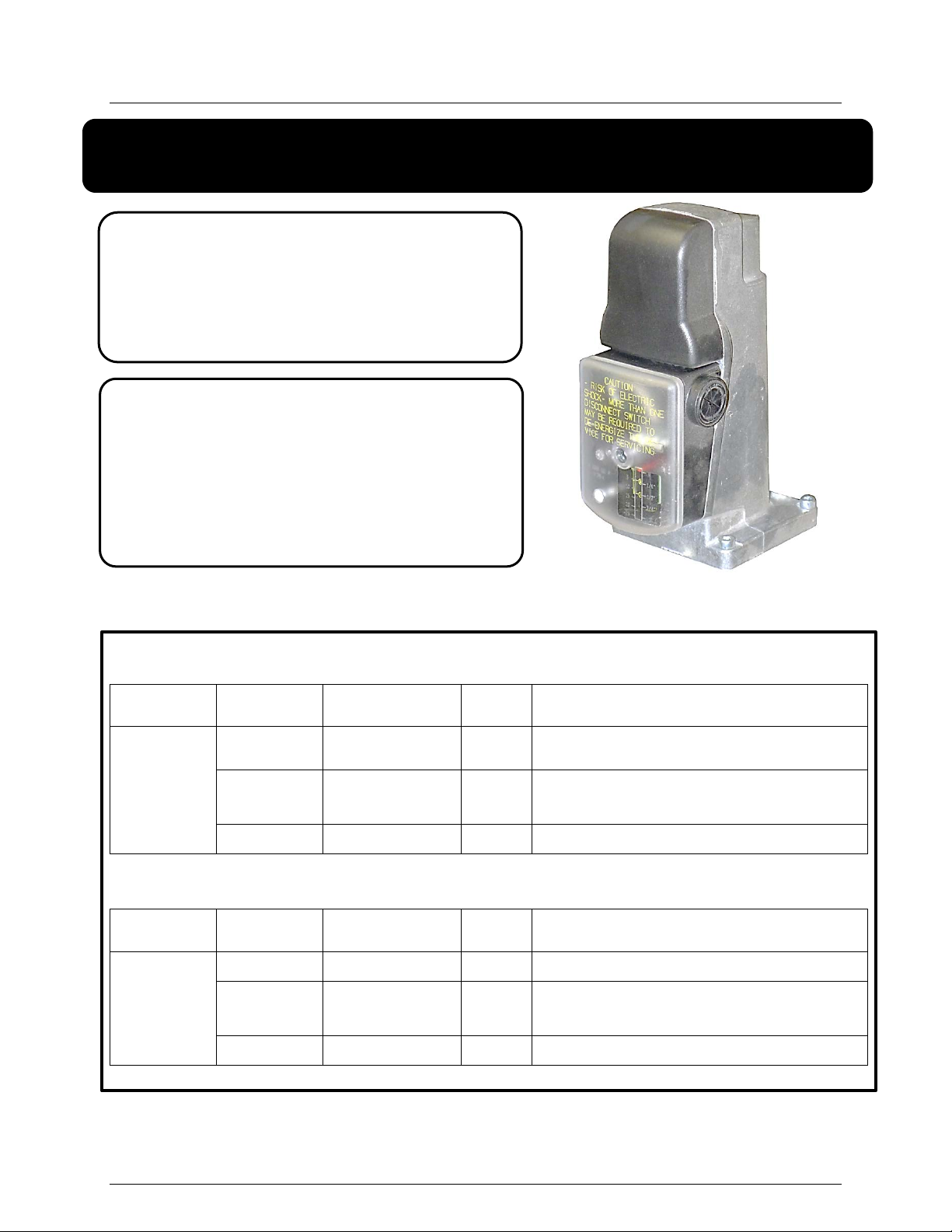
Gas Valve Actuator
Replacement Kit
Description of Document:
This TID provides the procedures to
replace and set up the Siemens Gas
Valve Actuator in all AERCO boilers
featuring double-block and double-
block-and-bleed gas trains.
Actuator Replacement Kit for AERCO Boilers, P/N 27086-1
Boilers ITEM PART NO. QTY DESCRIPTION
All AERCO
Boilers
(except
BMK6000)
1 12951-4 1 Control Box Bushing
2 69038 1
3 TID-0092 1 Instruction Document
Actuator, Siemens SKP15.013U1
(without POC switch)
Boilers ITEM PART NO. QTY DESCRIPTION
BMK6000
Last Revised: 01/28/2015
VD2: 01/28/2014 AERCO International, Inc. • 100 Oritani Dr. • Blauvelt, New York 10913 • Phone: 800-526-0288 Page 1 of 9
Actuator Replacement Kit for BMK6000 Boilers, P/N 27086-2
1 12951-4 2 Control Box Bushing
(Only)
2 124138 1
3 TID-0092 1 Instruction Document
Actuator, Siemens SKP15.012U1
(with POC switch)
Page 2

Sieme n s Gas Valve Actuator Replacement Kit # 27086-TAB Instructions
Technical Support:
1-800-526-0288
www.aerco.com
Technical Instruction Document TID-0092_0E
TABLE OF CONTENTS
1. INTRODUCTION ................................................................................ 3
2. SPECIFICATIONS .............................................................................. 3
3. DIMENSIONS..................................................................................... 4
4. REQUIRED TOOLS ............................................................................ 4
5. REPLACEMENT KIT CONTENTS ...................................................... 4
6. PREPARATONS ................................................................................. 5
7. REPLACEMENT PROCEDURE ........................................................... 6
(Mon–Fri, 8am-5pm EST)
Disclaimer
The information contained in this manual is subject to change without notice from
AERCO International, Inc. AERCO makes no warranty of any kind with respect to this
material, including, but not limited to, implied warranties of merchantability and fitness for
a particular application. AERCO International is not liable for errors appearing in this
manual. Nor for incidental or consequential damages occurring in connection with the
furnishing, performance, or use of this material.
VD2: 01/28/2014 AERCO International, Inc. • 100 Oritani Dr. • Blauvelt, New York 10913 • Phone: 800-526-0288 Page 2 of 9
Page 3

Sieme n s Gas Valve Actuator Replacement Kit # 27086-TAB Instructions
Dimensions
See Figure 1
Technical Instruction Document TID-0092_0E
1. INTRODUCTION
The Siemens electro-hydraulic gas valve actuators are used in combination with VG series gas
valves to provide safety shut-off control for industrial and commercial burner applications. It is
featured in all double-block and double-block-and-bleed gas trains used in AERCO boilers.
The electro-hydraulic actuator consists of a cylinder filled with oil, a piston containing an electric
oscillating pump, and a relief system. When power is supplied to the actuator, the relief system
closes, and the pump moves oil from the reservoir into the pressure chamber. This action
causes the piston to move downward in the cylinder, opening the gas valve. When power to the
actuator is interrupted, the relief system opens and the gas valve closes in less than 0.8
seconds. A position indicator, visible through the transparent portion of the terminal cover,
shows the entire stroke range of the actuator. A light, which is visible through the lower left
transparent portion of the terminal cover, indicates when the actuator receives power. An
optional, non-adjustable SPDT proof of closure over travel switch signals the closed position
after the gas valve has closed. An optional SPDT auxiliary switch is adjustable between 40%
and 100% of the stroke. The adjustment screw and scale are located on the right side in the
terminal box, and are visible through the transparent portion of the terminal cover.
2. SPECIFICATIONS
Agency approvals
Power Supply
Operating
Environment
Physical
Characteristics
Connections
As Safety Shut-Off Valve
Operating Voltage 110 to 120 VAC + 10% to -15%
Operating Frequency 50 to 60 Hz + 6%
Power Consumption 3.5 VA
Duty Cycle Continuous
Ambient Operating Temperature 5°F to 140°F (–15°C to 60°C)
Mounting Position Any position except upside down
Weight 2.4 lb (1.1 kg)
Enclosure
Conduit Connection
Electrical Connection
UL/429, FM/7400, ANSI
Z21.21/CGA6.5 C/I
NEMA 1, 2, 5, and 12 for indoor
use
Two 1/2-inch NPSM threaded
knock-outs
Spring loaded terminals for 14
AWG wires
Output Force 100 lbs. (450 N)
Operating
Characteristics
VD2: 01/28/2014 AERCO International, Inc. • 100 Oritani Dr. • Blauvelt, New York 10913 • Phone: 800-526-0288 Page 3 of 9
Maximum Stroke 1 inch (26 mm)
Opening Time For Maximum
Stroke
Closing Time <0.8 seconds
Varies with valve size, 14 seconds
for maximum stroke.
Page 4

Sieme n s Gas Valve Actuator Replacement Kit # 27086-TAB Instructions
Boilers
ITEM
PART NO.
QTY
DESCRIPTION
Boilers
ITEM
PART NO.
QTY
DESCRIPTION
1
12951-4
2
Control Box Bushing
(with POC switch)
3
TID-0092
1
Instruction Document
Technical Instruction Document TID-0092_0E
3. DIMENSIONS
Figure 1: Actuator Dimensions
4. REQUIRED TOOLS
The following tools are required to perform the instructions in this bulletin.
Standard set of screwdrivers
4mm Allen key driver
5. REPLACEMENT KIT CONTENTS
The contents of replacement kits are shown in Tables 1 and 2, below:
Table 1: Actuator Replacement Kit, P/N 27086-1 (All BMK, Except BMK 6000)
All AE R C O
Boilers
(except
BMK6000)
Table 2: Actuator Replacement Kit, P/N 27086-2 (BMK 6000 Only)
1 12951-4 1 Control Box Bushing
2 69038 1
3 TID-0092 1 Instruction Document
Actuator, Siemens SKP15.013U1
(without
POC Switch)
BMK6000
(Only)
VD2: 01/28/2014 AERCO International, Inc. • 100 Oritani Dr. • Blauvelt, New York 10913 • Phone: 800-526-0288 Page 4 of 9
2 124138 1
Actuator, Siemens SKP15.012U1
Page 5

Sieme n s Gas Valve Actuator Replacement Kit # 27086-TAB Instructions
Technical Instruction Document TID-0092_0E
6. PREPARATONS
To prepare the boiler for the retrofit, perform the following:
• Remove power from the unit by shutting off electrical power upstream from the boiler.
• Turn off the supply gas upstream from the boiler.
WARNING
HIGH VOLTAGES OF 120 VAC, 220 VAC OR 460 VAC
ARE USED IN AERCO BOILERS. IT IS REQUIRED TH AT
ALL POWER APPLIED TO THESE BOILERS IS
REMOVED FIRST BEFORE PERFO RMING ANY OF THE
PROCEDURES DESCRIBED IN THIS DOCUMENT. USE
EXTREME CARE WHEN ACCESSING CIRCUITS AND
ELECTRICAL CONNECTIONS WI THIN THE EQUIPMENT.
SERIOUS PERSONAL INJURY OR DE ATH MAY OCCUR
IF THIS WARNING IS NOT OBSERVED.
IMPORTANT!
Observe local requirements and lockout procedures when working
on the boiler.
Personal injury or loss of life may occur if procedures are not
followed as specified. All installations must be performed by
qualified personnel only.
Do NOT pull the actuator shaft of the actuator.
WARNING
WARNING
VD2: 01/28/2014 AERCO International, Inc. • 100 Oritani Dr. • Blauvelt, New York 10913 • Phone: 800-526-0288 Page 5 of 9
Page 6

Sieme n s Gas Valve Actuator Replacement Kit # 27086-TAB Instructions
VG Series
Valve Body
4mm Allen
(x4)
Semi-Transparent
Cover
Technical Instruction Document TID-0092_0E
7. REPLACEMENT PROCEDURE
Replacement instructions for the actuator are as follows:
1. After ensuring that all electrical power is removed from the boiler, remove boiler side panels
as necessary to access the actuator. Depending upon the boiler model, the actuator may be
installed at any angle except upside down. The example shown in Figure 2 is a double-block
gas train.
2. Use a standard Phillips head screwdriver to remove the screw holding the semi-transparent
wiring compartment cover of the old actuator and make a note of all wire connections.
3. After making a note of the wire connections, release the wires from the connections by
pushing down on the spring loaded lever under each wire terminal and remove wires.
4. Pull all loose wires from out of the wire conduit in the side. A spare bushing for the wiring
conduit hole is included in the kit in case it is needed.
5. Remove the four 4mm Allen bolts that hold the actuator to the valve body (Figure 2) and
then remove the actuator.
6. Install new actuator from replacement kit and affix to valve body with 4mm Allen bolts
captured in the body of the new actuator.
7. On all BMK 1.5 – 3000 models, and on BMK 6000 units with the newer actuator shown in
Figure 4, remove the new actuator cover, punch out the holes in the plastic to accommodate
the wiring, then insert the wires through wire conduit and wire it identically to the old
actuator. Skip this step on older BMK 6000 units with the original actuator (which included
an Auxiliary Switch Adjustment Screw) as shown in Figure 5, and complete Step 8, below.
Siemens Actuator
(P/N 69038 or
124138)
Wire Compartment
Keyed Bolts
VD2: 01/28/2014 AERCO International, Inc. • 100 Oritani Dr. • Blauvelt, New York 10913 • Phone: 800-526-0288 Page 6 of 9
Figure 2: Actuator Installati on on Valve Body
Page 7

Sieme n s Gas Valve Actuator Replacement Kit # 27086-TAB Instructions
Wire Conduit
Opening
Cover
Wire
Conduits
Wire Conduit
Opening
Actuator, P/N 69038 Actuator, P/N 124138 (BMK 6000 Only)
Technical Instruction Document TID-0092_0E
Semi-
Transparent
Figure 3: Actuator External Features
Electrical
Ground
Screw
Wire
Terminals
Cover Screw
Transparent
Window showing
Valve Position
Valve
Position
Indicator
Figure 4: Actuator Wiring Compartment
VD2: 01/28/2014 AERCO International, Inc. • 100 Oritani Dr. • Blauvelt, New York 10913 • Phone: 800-526-0288 Page 7 of 9
Page 8

Sieme n s Gas Valve Actuator Replacement Kit # 27086-TAB Instructions
WIRE 153 – TO C-MORE
Auxiliary Switch
LOW GAS
LOW GAS
Technical Instruction Document TID-0092_0E
8. Complete this step ONLY on BMK 6000 units with the original actuator, as shown in
Figure 5. Remove the new actuator cover, punch out the holes in the plastic to
accommodate the wiring, then insert the wires through wire conduit and wire it as follows:
• Wire Terminals 4, 5, N, N, L and L identically to the old actuator
• Remove & dispose of the two wires attached to Terminals 1 and 2 and wire nut, and the
wire connecting Terminal 3 to the Low Gas Pressure Switch (dashed lines)
PRESSURE
SWITCH
(DUNGS)
Adjustment Screw
Older Actuator Before Replacement, P/N 124138 (BMK 6000 Only)
Figure 5: Wiring Compartment
9. Disconnect Wire 153 (dotted line) from Terminal 3 and connect it to the Low Gas Pressure
Switch.
PRESSURE
SWITCH
(DUNGS)
WIRE 153 – FROM C-MORE
VD2: 01/28/2014 AERCO International, Inc. • 100 Oritani Dr. • Blauvelt, New York 10913 • Phone: 800-526-0288 Page 8 of 9
Figure 6: Wiring Diagram After Replacing Actuator
--- END ---
Page 9

Sieme n s Gas Valve Actuator Replacement Kit # 27086-TAB Instructions
Technical Instruction Document TID-0092_0E
Change Log
Date Description Changed By
11/24/2014
1/28/2015
Rev D:
PIR 839-2: Replace 69171 with 124138 in kit # 27086-2
Rev E:
PIR 934-155: Added Figures 5 & 6 and steps 8 & 9 to
explain how to wire older BMK 6000 Actuators
Chris Blair
Chris Blair
International Inc.
© AERCO International, Inc., 2015
VD2: 01/28/2014 AERCO International, Inc. • 100 Oritani Dr. • Blauvelt, New York 10913 • Phone: 800-526-0288 Page 9 of 9
 Loading...