

Page 1

© Siemens 2020 1
24 V nonstop –
even upon
power failure
The right UPS system for every
application –
summary of advantages and
disadvantages
A reliable power supply is essential for guaranteeing the productivity of automated
plants and machines. PLCs, sensors and actuators are usually provided with
24 V DC from a switched-mode power supply. Modern power supply units such as
SITOP offer a maximum degree of security for the supply. However, they are not
invulnerable to longer power supply failures. Critical applications therefore require
upgrading to an uninterruptible power supply. But which UPS system is the right
one, and what must be considered when dimensioning?
Page 2
Application Note | 24 V nonstop – even upon power failure
© Siemens 2020 2
AC or DC UPS?
In order to provide protection against power failure, an uninterruptible power supply can be used on the AC or DC
side. The advantage of an AC UPS is that it provides buffering of all electrical consumers, e.g. also of AC drives. However, an AC UPS is more expensive than a DC UPS. If it is permissible with the application to only buffer the 24 V side in
the event of a power failure, a DC UPS is quite definitely the
more economical solution. On the one hand, the powers required are usually smaller, resulting in smaller dimensioning
of the DC UPS, and on the other hand an AC UPS is always
more expensive because of its increasingly complex design.
Furthermore, the total efficiency is significantly better with
a DC UPS. This is because conversion of the battery voltage
into an AC voltage and the repeated transformation into the
required 24 V DC voltage are unnecessary.
With the DC UPS, the energy is provided where it is required, namely directly on the consumer without "loss-making detours".
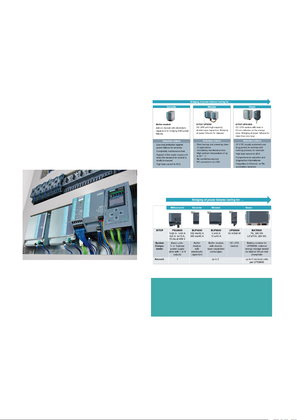
The right solution for every application
No other manufacturer of power supplies provides such a
comprehensive range of units for safeguarding a 24 V DC
supply like Siemens does. The range extends from a simple
buffer module up to the multi-function DC UPS.
24V DC power supply from SITOP can be combined with
A
3 different solutions for 24V buffering:
Additionally to the above 3 solutions, the PSU8600 offers
its own solution for buffering ranging from millisecond to
hours.
Figure 1: Buffering the 24V control circuit with the SITOP PSU100S
power supply, SITOP DC-UPS UPS1600 and 2 battery modules SITOP
UPS1100. The DC-UPS is fully integrated via PROFITNET in the
automation system.
Note:
The SITOP PSU8600 system power supply and its buffering
technologies merit its own application note. For more information, please see www.siemens.com/sitop-psu8600
for more information.
Page 3

Application Note | 24 V nonstop – even upon power failure
© Siemens 2020 3
Bridging brief power failures
When power supply conditions are unstable, for example
in low-meshed network infrastructures, brief power failures may occur occasionally or even frequently as a result
load transfers in the network, for example. Problems following such interruptions with non-buffered power supplies are the long ramp-up times and initialization of the
automation system or involved drives. It is already possible
to significantly increase the plant availability by using a
buffer module for bridging such brief interruptions of up
to 10 seconds. The buffer module is simply connected in
parallel with a 24 V SITOP power supply. The electrolytic
capacitors supply up to 40 A which supports the power
supply even in the event of an overload.
Protection of plant status upon power failure
In applications where a plant is to be switched off in the
event of a power failure with retention of the last plant
status, extended bridging of the power failure is required.
Such requirements are typical for PC-based automation,
visualization, or archiving of operating data. Recording of
the failure, saving of the plant status, as well as controlled
shutdown of the PC require bridging in the minute range.
Comparatively high buffer reserves are required in such a
scenario by powerful industrial PCs, especially when a
large panel has to continue to operate during the shutdown. High buffer capacities are also required by actuators
which have to be driven into an end position or processes
in which plant components must continue to be powered
until the power supply is restored. This is the case, for example, when measured data is being recorded or a communications link must be maintained. Uninterruptible
power supplies (UPS) are required in such situation
SITOP power supplies with 24 V output voltage can be upgraded into a fully-fledged UPS. Two different UPS concepts are available corresponding to the mentioned requirements. They mainly differ in the type of energy store.
One of them is based on lead or lithium batteries, the
other on double-layer capacitors. All DC UPS modules have
the same basic functionality with comprehensive monitoring functions and signaling contacts and are available with
a USB interface. The battery based SITOP UPS1600 is also
available with an Industrial Ethernet/PROFINET interface
and communicates also over OPC UA.
The free software tool SITOP Manager provides simple integration into PC-based automation solutions. They support further processing of status messages, safe shutdown, and correct restarting of the system. The UPS1600
with IE/PN interface can be configured via the TIA Portal or
integrated in TIA (Totally Integrated Automation) with
STEP 7 and WinCC
The energy storage makes the difference
Whether the capacitor-based or the battery-based concept
is right for the respective application depends on the respective demands. If long buffer times are required, the
UPS with batteries is the best choice. They can supply energy for hours depending on the current requirements.
Battery modules for the UPS1600 are available with capacities ranging from 1.2 Ah to 12 Ah. Connection in parallel
allows for a flexible combination for the required capacity,
up to 72 Ah. A UPS1100 battery module is equipped with
electronics with specific parameters as well as for recording the current operating data that are read by the
UPS1600 UPS module via a two-wire cable (Energy Storage
Link).
The UPS modules are available with rated output currents
of 10 A, 20 A and 40 A. They also offer high overload capability and can supply three times the rated current for 30
ms and 1.5 times the rated current for 5 s per minute.
In many cases, a plant can be brought into a safe status
within minutes, and thus minimize the effects of a power
failure. Many advantages for such time requirements are
provided by the SITOP UPS500 based on double-layer capacitors. These are also referred to as ultracaps, supercaps
or super capacitors because of their high energy density.
The innovative UPS for installation in control cabinets consists of a basic unit with energy storage of 2.5 or 5 kWs,
and delivers an output current of up to 15 A. Add-on modules of 5 kWs each permit configurations with up to 20
kWs.
The type of energy storage is not only critical for the buffer
time, is also decisive for the possible applications of the
two types of SITOP UPS systems.
Available capacity of lead batteries is highly dependent
on the temperature
Lead batteries are extremely temperature-sensitive, since
the charging and discharging processes of a battery are
the result of an electrochemical reaction. Aging depends
on the electrolyte used (sulfuric acid) and the plates serving as poles (lead and lead oxide) and is highly temperature-dependent. Temperatures higher by 10 K reduce the
service life by half. With an ambient temperature of 40 °C,
for example, the service life is therefore only 1/4 of that
at the rated operating temperature of 20 °C. A lead battery with a service life of 4 years at the rated conditions
must therefore be replaced after only one year when used
at 40 °C.
Special batteries with an increased thermal stability can
also be used as an alternative to conventional lead batteries, but these are also more expensive. SITOP offers, for
example, a high-temperature battery with pure lead
plates for use at temperatures from -40 to +60 °C.
Page 4

Application Note | 24 V nonstop – even upon power failure
© Siemens 2020 4
Lithium based batteries with longer lifetime, even at
high temperatures
Batteries using lithium, such as lithium iron phosphate
(LiFePO4), bring together high temperature resilience and
long lifetime. At 40°C, the lithium batteries are rated for 9
years, where traditional lead-acid batteries are rated for
only 1 year. This dramatic difference makes the amortization of the valuable lithium technology possible over just a
few years.
Table 1: Service life and ambient temperature range of SITOP
UPS1100 battery modules
How supercaps work and the advantages they offer
A chemical reaction does not take place in double-layer capacitors. They store the charge in an electrochemical double layer (the so-called Helmholtz layer), where positive
and negative ions of the electrolyte move through the
electric field to the corresponding electrode. They are
therefore more resistant to aging than lead batteries, with
regard to both the charging cycles and the temperature. In
the SITOP UPS500, the supercaps only lose approx. 20% of
their capacity after eight years of operation
and an ambient temperature of 50 °C. The UPS is therefore
fully maintenance-free, and replacement of the energy
storage is unnecessary.
Even at an ambient temperature of 40 °C, the capacitor
UPS is amortized in the second year of operation. The
slightly higher cost is compensated by the second battery
replacement for a conventional UPS.
Even more costs can be saved regard to the control cabinet
installation. Compared to lead batteries, the capacitors do
not emit hydrogen and there is therefore no need to ventilate the control cabinet.
An additional advantage provided by the energy storage is
the short charging time of a few minutes (see table 2
"Buffering and charging times SITOP UPS500"). This guarantees fast supply readiness following a power failure and
also results in a high availability.
How is a DC UPS system configured?
The criteria for configuration of the UPS are the buffer
time, the operating current, the peak current and the
ambient temperature. The example below shows the
configuration of a DC UPS, which is designed to protect
an automation application with a 24 V industrial PC
from a power failure.
The backup is intended for a Panel PC that is to save
data and shut down normally in the event of a power
failure. To retain or save the measured values, the sensors should also be supplied with 24 V via the DC UPS.
To lower the load on the DC UPS, the actuators are not
to be buffered and are connected directly to the 24 V
output of the power supply
Figure 2: Application example for configuration of an uninterruptible 24 V power supply
Application conditions:
Time required to save and shut down the system: 55 s, ambient temperature: 40 °C, actuators are not buffered.
1) Calculation of current requirements and selection of
power supply
a) Calculation of max. operating current requirement:
Buffered 24 V feeder: 3.4 A (PC 477E) + 0.5 A (sensors) +
2 A (UPS500S charging current, can be set to 1 or 2 A) =
5.9 A
Non-buffered 24 V feeder: 3 A (actuators)
Total operating current requirement: 5.9 A + 3 A = 8.9 A
b) Calculation of peak current requirement:
Buffered 24 V feeder: 6.5 A (PC 477E for 25ms) + 1 A
(sensors) + 2 A (charging current) = 9.5 A
Non-buffered 24 V feeder: Actuators: 4 A (starting
torque)
Total peak current requirement: 9.5 A + 4 A = 13.5 A
c) Selection of power supply for 8.9 A operating current
and 13.5 A peak current requirement
=> SITOP PSU6200 10 A (max. 15 A for 5 s)
2) Calculation of UPS output current, energy storage and selection of DC UPS
a) UPS output current at peak current requirement:
6.5 A (PC 477E for 25 ms) + 1 A (sensors) = 7.5 A
b) UPS output current for buffer mode:
3.4 A (PC 477E) + 0.5 A (sensors) = 3.9 A
c) Energy requirement + 25% due to 20% loss in capacity af-
ter
approx. 8 years: 3.9 A x 24 V x 55 s x 1.25 = 6435 Ws
Check in table for UPS500 "Buffering and charging
times":
Buffering time with 4 A operating current and 7.5 kWs:
61 sec = OK!
d) Selection of DC UPS for 7.5 A peak output current and
6.435 kWs => SITOP UPS500S 15A/ 2.5 kWs and add-on
module SITOP UPS501S 5 kWs (total 15A/ 7.5 kWs)
Page 5

Application Note | 24 V nonstop – even upon power failure
© Siemens 2020 5
Table 2: Check in the table Buffering and charging times
SITOP UPS500
TIA Selection Tool – convenient selection guide for
power supply and DC UPS
The selection with the 24 V consumer view in the TIA Selection Tool is more convenient and detailed than the manual selection, especially for the more demanding dimensioning of a DC UPS with batteries. The selection guide offers the possible DC UPS solutions with a few mouse clicks,
depending on the requirements, with capacitors or batteries.
In addition to the criteria operating current and buffer
time, you can also specify the ambient temperature, the
minimum buffer voltage and new the target lifetime of the
batteries. The minimum buffer voltage is the lowest input
voltage at the load at which its function is still guaranteed.
It influences the dimensioning of a DC UPS with battery.
This is because if the battery voltage drops more, a longer
buffer time is possible with the same battery capacity. The
ambient temperature plays a crucial role for the service life
of a battery, as described on page before.
The new option „target lifetime of the batteries” will dimension the battery capacity to offset the natural aging
process of the batteries for the specified lifetime. This implies that, for example, a customer selects a target lifetime
of 3 years, the battery configuration will be dimensioned
to provide the request buffer capacity after 3 years. This
aging is modeled using the Arrenius’s Law and is compensates the capacity degradation by increasing the battery
capacity. With these added features, TIA Selection Tool
can model the real conditions even better, saving the arduous calculations necessary to do such modeling manually.
The matching power supply as well as all the Add-on
modules can be selected just as conveniently from the
vast range of SITOP products. The tool compiles all required CAD data, circuit diagram macros and appropriate
documentation for the selected power supply and the DC
UPS to enable quick configuration.
www.siemens.com/tst
Figure 3: After entering a few criteria, the TIA Selection Tool
offers a selection of suitable DC UPS configurations.
Page 6

Application Note | 24 V nonstop – even upon power failure
© Siemens 2020 6
DC UPS
Communication
Control-
Engineering
Digital outputs
PLC
-
USB
PC
SITOP Manager
Digital outputs
PLC
-
USB
PC
PC
STEP 7, TIA
Portal
How is the DC UPS integrated into the plant?
The automation system must be informed about the
status of the DC UPS so that it can respond correctly to
the situation. Communication takes place via digital
outputs, USB or Ethernet/PROFINET interfaces.
ler
SITOP UPS500
(with ultracaps)
SITOP UPS1600
(with battery modules)
Table 3: A free engineering tool is available for the DC UPS
with interface and controller type that must be buffered; it can
be used for easy configuration of the DC UPS and visualization
of the operating state
Industr. Ethernet/
Profinet
PLC
tool
SITOP Manager
Digital outputs
The most important status messages are displayed by
LEDs for all SITOP DC UPS modules and output via signaling contacts. The signals are evaluated by digital inputs at the controller. Signaling and terminal assignment are identical for the DC UPS modules SITOP
UPS500S and SITOP UPS1600 (see Table 4), which
means engineering and wiring of both UPS systems is
almost the same.
Tab le 4: The digital outputs of all SITOP DC UPS modules are
the uniform in accordance to this terminal assignment.
The use of relay contacts is ideally suited for basic automation applications without networking, such as obstruction lighting, hydroelectric plants or thermal power
stations. For these insular applications, the UPS1600 is
especially equipped with the "Start from Battery" function. When a plant is started without line voltage, the
24 V loads are supplied by the battery.
Figure 4: Backing up simple automation applications with status signaling via digital outputs.
The UPS settings are made on the front of the device.
Among other things, you can set the voltage connection
threshold, the buffer time and the operating current
with DIP switches or rotary switches. For the coded
UPS1100 battery modules, the operating current is predefined, depending on the temperature, via the 2-wire
cable "Energy Storage Link" and therefore need not be
set.
Interfaces for PC-based or PLC-based systems
For communication with PCs or PLCs, the SITOP DC UPS
modules come equipped with an optional USB port or
two Ethernet interfaces. Free engineering tools, which
should be used according to Table 3, assist in the integration of the DC UPS into the plant.
SITOP UPS500 with USB port on the PC
UPS modules with USB port are best suited for applications with an automation computer and without further
networking. The UPS500 responds via USB port to the
same status messages that are also output via the contacts (see Table 4). The UPS 500 can be easily configured with the SITOP Manager from Version 1.1, which
means it can be used to start applications at specific
events, such as an emergency program in case of a
power failure or buffer mode.
Page 7

Application Note | 24 V nonstop – even upon power failure
© Siemens 2020 7
Figure 5: Backing up a 24 V automation computer with communication via USB
The "Reset after Buffering" function is available for the
versions with USB as well as Industrial Ethernet. Without
this function, the computer remains switched off during
shutdown when the power and therefore the 24 V supply returns. With this function, the 24 V supply is interrupted for 5 seconds after shutdown (interface is not
supplied with voltage) which makes the computer start
up automatically again.
A general disadvantage of communication via USB is the
restriction to a cable length of about 5 meters if no additional measures for signal amplification are taken.
SITOP UPS1600 with USB port or Industrial Ethernet
interface on PC
If the UPS1600 backs up PC-based controllers, communication can take place via USB or Industrial Ethernet (IE).
Communication via the two 2 IE ports has the great advantage that the UPS can be easily integrated into any LAN
infrastructure and multiple PCs can be shut down according to the master-slave principle if a power failure occurs.
Figure 6: Backing up multiple 24 V PCs. Communication via Industrial Ethernet supports comprehensive diagnostics and targeted
shutdown in the master-slave module in case of power failure
Parameters can be conveniently assigned via the SITOP
Manager. Now with Version V1.1, all SITOP devices with
USB or PN/IE communication can be configured and diagnosed.
SITOP Manager runs on Windows 7 and 10 and offers:
• Online- and Offline-Engineering
• Commissioning and continuous monitoring
• Monitoring and controlled shutdown of multiple PCs in
the event of a power failure, for example, by starting
batch files and closing software applications
• Online functions, such as firmware updates
• Easy operation via web-based user interface
• automatic scaling to window width
• Remote access possible via mobile devices
Figure 7: With SITOP Manager, it is easy to parameterize and visualize the DC-UPS.
Download: Engineering Tool SITOP Manager
Remote visualization of the operating state and the parameters is also possible via the integrated web server. The device status along with the network connection can be easily monitored in the SINEMA Server or SINEC NMS network
management software.
SITOP UPS1600 with PROFINET at controller
For backing up SIMATIC controllers, the PROFINET connection and the TIA Portal offer optimal options for easy and
complete system integration. Function blocks for the SIMATIC S7-300, 400, 1200 and 1500 enable processing of
all UPS1600 operating data and therefore response to each
state of the DC UPS. The state of the DC UPS can evaluated
in detail especially when using the coded battery modules
UPS1100. Up to six UPS1100 battery modules can be
connected in parallel and evaluated individually.
Here is a selection of the UPS data that can be evaluated:
• Voltage and input current
• Output voltage and output current
• Charging voltage and charging current
• Temperature UPS1600 and UPS1100 battery modules
• Capacity of the battery in total and individually
• Remaining buffer time
• Number of battery modules
• Recommended battery replacement
Page 8

Application Note | 24 V nonstop – even upon power failure
© Siemens 2020 8
www.siemens.com/sitop
Subject to changes and errors. The information provided in this document contains
descriptions or performance
ways
the products. The desired
agreed in the contract. Availability and technical
without notice.
All product designations may be trademarks or product
plier companies, the use
violate the rights of the owners.
In addition, all device parameters can be read, for example, end-of-charge voltage, rated capacity, permissible
temperature range, article number, serial number and version number.
Figure 8: Backing up an automation solution with PLC networked
via PROFINET. Even multiple controllers can be brought to a defined state independent of each other
The operating status of the DC UPS can be easily visualized
using ready-to-use faceplates. Faceplates for SIMATIC Panels and WinCC make for easier diagnostics in the area of
production automation.
SITOP UPS with PROFINET on process control systems
A free UPS1600 library with software blocks and faceplates
is also available for the SIMATIC PCS 7 process control system. Automatic information about operating status messages such as power failure (buffer mode) or maintenance
demanded as well as preventive battery replacement increase availability of the plant in process automation even
more.
Figure 10: Faceplates for the SIMATIC PCS 7 enable easy diagnostics and maintenance of the DC UPS in the process industry
Download:
SITOP library for integration in SIMATIC PCS 7 V8.2 and
SIMATIC PCS 7 V9.0
Figure 9: Faceplates for WinCC help visualize comprehensive diagnostics including trend charts and alarm messages
Download:
SITOP UPS1600: Faceplates and STEP 7 communication
blocks
Published by
Siemens AG
Digital Industries
Process Automation
Östliche Rheinbrückenstr. 50
76187 Karlsruhe, Germany
apply as described or which may change as a result of further development of
characteristics which, in case of actual use, do not al-
performance characteristics are only binding if expressly
specifications are subject to change
names of Siemens AG or sup-
of which by third parties for their own purposes may
 Loading...