

Page 1
s
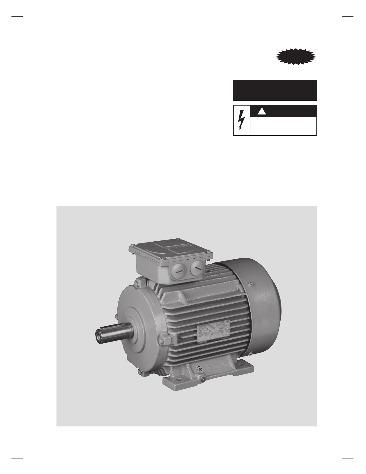
Installation . Operation .
Maintenance Instructions
!
WARNING
Supply Voltage is hazardous and can
cause Electric Shock and burns.
Disconnect Power before proceeding with
any work on this equipment.
Operating Instruction and
Maintenance Manual
Three-phase induction motor Type 1SE0/1LA2
63-132 frame sizes
IE Motors
Page 2

2
Table of Content
Pg. No.
1. Safety information ............................................................................................ 3
1.1 Denitions, warning information ...............................................................3
1.2 Safety and application information ............................................................ 5
2. Description .......................................................................................................5
2.1 General ..................................................................................................... 5
2.2 Terminal Box ............................................................................................. 5
3. Operation ....................................................................................................... 6
3.1 Inspection, storage and transport .............................................................. 6
3.2 Mounting .................................................................................................. 7
3.3 Installation ................................................................................................ 7
3.4 Electrical connection ................................................................................. 8
3.4.1 Earthing ..........................................................................................9
3.5 Checking the insulation resistance ............................................................. 9
3.6 Bearing and lubrication............................................................................ 10
3.7 Balancing, Transmission elements ............................................................ 10
3.8 Commissioning ....................................................................................... 10
4 Electromagnetic Compatibility ........................................................................ 12
5 Maintenance ................................................................................................... 12
5.1 General ................................................................................................... 13
5.2 Dismantling............................................................................................. 13
5.2.1 Pressing on and pulling off drive elements ..................................... 13
5.2.2 Fans .............................................................................................. 13
5.2.3 Removal of bearing ........................................................................ 14
5.3 Reassembly ............................................................................................. 14
6 Spare Parts ..................................................................................................... 15
Applicable Standards ......................................................................................... 15
7 Motor Troubleshooting Chart .......................................................................... 16
Fig.1 Exploded view for Frame Size upto 132 .................................................... 18
Fig.2 Pressing on and pulling off drive elements, changing bearings ................ 19
Fig.3 Terminal Box for 63, 71, 80, 90S and 90L frames .................................... 20
Fig.4 Terminal Box for 100L, 112M, 132S and 132M frames ............................. 21
Page 3
3
1 Safety information
1.1 Denitions, warning information
General Note
Warning
The data and recommendations
specied in all the instructions supplied,
and in all other related instructions,
must always be observed in order to
avoid hazardous situations and the
risk of possible injury or damage.
Furthermore, the pertinent national,
local and plant-specic regulations
and requirements should be kept in
mind!
Special designs and other versions
may vary in technical details! If
in doubt, be sure to contact the
manufacturer, quoting the type
designation and serial number, or
have maintenance work done by one of
SIEMENS Service Centers.
Warning
The disposal of waste generated during
operation & maintenance of the motor
should be done as per the applicable
local environmental legislations.
• Waste grease & greased cloth to be
collected as hazardous waste and
sent to hazardous waste disposal
facility for incineration.
• Waste copper windings to be
collected as hazardous waste and
sent to registered recyclers approved
by the respective State Pollution
Control Board.
Qualied persons
Only qualied persons who have carefully
read and understood the content of this
documentation should be entrusted with
the commissioning and operation of
machines, equipment or systems. Qualied
persons as far as the safety instructions
given in this documentation are concerned
are those who have the necessary
authorization to commission, earth and
identify equipment, systems and circuits
in accordance with the relevant safety
standards.
Safety guidelines
This documentation contains instructions,
which must be followed closely in order to
ensure personal safety and avoid damage
to the equipment and machines.
Personal safety instructions are highlighted
in the manual by a warning triangle,
while damage avoidance instructions are
marked as follows depending on the level
of danger:
Danger
Danger means that death or grievous
injury will occur if the appropriate
precautions are not taken.
Warning
Warning means that death or grievous
injury may occur if the appropriate
precautions are not taken.
Page 4
4
Caution
Caution with a warning triangle means
that minor personal injury may occur
if the appropriate precautions are not
taken.
Caution
Caution without a warning triangle means
that damage to property may occur if the
appropriate precautions are not taken.
Notice
Notice means that an undesirable result
or state might occur if the relevant
instructions are not followed.
Note
Note draws particular attention to an
important item of information about the
product, its use or the corresponding
section of the documentation, which could
be useful to the user or operator.
Proper usage
Please pay close attention to the following:
Warning
The electrical equipment contains
components that are at a dangerous
voltage. Before any work is carried out,
it must be ensured that the equipment
is isolated from the supply.
Only qualied persons may work with
this equipment.
These persons must be familiar with all
instructions and precautions to be taken
/ specied in this documentation that
are relevant for safety.
Safe and satisfactory operation of
this motor presumes satisfactory
transport, proper storage, installation
and assembly and careful subsequent
operation and maintenance.
This motor may only be used for the
applications specied in the catalog
and the technical description or for
which it is seleteced, and only in
conjunction with third-party devices
and components recommended and/or
approved by SIEMENS.
Failing to adhere to these instructions
may result in severe injury and/or
damage to property.
National safety regulations must be
closely observed.
Page 5
5
1.2 Safety and application information
The safe use of electrical machines
Danger
These electrical machines are designed
for use in industrial power systems.
Rotating or live and uninsulated parts
pose a danger.
There is consequently a risk of
fatal or severe personal injury or
substantial damage to property if the
necessary covers are removed without
authorization or if the equipment
is handled improperly, operated
incorrectly or maintained inadequately.
If the motors are used outside industrial
areas, the installation site must be
safeguarded against unauthorized
access by means of suitable protection
facilities (e.g. fencing) and appropriate
warning signs.
The persons responsible for the safety
of the system are under an obligation to
ensure that:
• The basic planning work for the system
and all work relating to transportation,
assembly, installation, commissioning,
maintenance and repairs are carried out
by qualied persons and checked by
responsible, suitably skilled persons.
• These instructions and the motor
documentation are made available at all
times while work is in progress.
• The technical data and specications
relating to the permissible installation,
connection, ambient and operating
conditions are taken into account at all
times.
• The system-specic erection and safety
regulations are observed and personal
protective gear is used.
• Work on these machines, or in
the vicinity of these machines, by
unqualied persons is prohibited.
These instructions therefore only contain
the information, which is necessary for the
motors to be used by qualied persons in
accordance with their intended purpose.
Note
We recommend engaging the support
and services of your local SIEMENS service
center for all planning, installation,
commissioning and maintenance work.
2 Description
2.1 General
The Champion series motors are three
phase cage induction motors, totally
enclosed fan cooled (TEFC) type for low
voltage supply. General-purpose motors
type 1SE0/1LA2 conform to IS:12615. The
motors comply with the type of protection
IP55 in accordance with IS 4691/IS/IEC 60034-5. The degree of protection of the
motor is specied on the rating plate.
IMB3 is the standard mode of construction.
Other constructions are given on customer
request.
Unless otherwise specied, the rated
outputs apply to continuous duty (S1) at a
frequency of 50 Hz, an ambient temperature
between 0°C and 50°C and site altitude not
exceeding 1000m above mean sea level.
2.2 Terminal box
The terminal box conforms to type of
protection IP55 in accordance with IS:4691/
IS/IEC - 60034-5.
For foot-mounted motors, the terminal box
is provided on the top with cable entry from
RHS (as seen from drive end) as a standard
feature. If specically ordered, terminal box
Page 6
6
position on the right or the left-hand side
(when viewed from the drive end) can be
supplied for frame size 90 and above.
In order to provide for different directions
for cable entry, the orientation of the
terminal box can be altered in steps of 90°.
In case of motor provided with Brake, the
possibility of terminal box rotation in steps
of 90° to be checked physically.
3 Operation
Warning
Before starting any work on the
machine, be sure to isolate it from
the power supply.
Warning
All covers which are designed to
prevent active or rotating parts from
being touched, or which are necessary
to ensure correct air guidance and thus
effective cooling, must not be opened
during operation.
All deviations from normal operation
(higher power consumption,
temperature or vibration level,
unusual noises or odours, tripped
monitoring devices, etc.) are
indications that the motor is no longer
functioning correctly. In such cases,
the maintenance technician must be
immediately notied in order to prevent
disturbances that could either directly
or indirectly lead to severe personal
injury or substantial material damage.
If in doubt, power-down the motor
immediately in conformance with the
system-specic safety requirements!
Caution
The surfaces of the machines can reach
high temperatures, which can lead to
burns in case of contact. Appropriate
measures to avoid accidental contact
must be taken.
3.1 Inspection, Storage & Transport
Warning
The motors may only be transported
and hoisted in a position corresponding
to their type of construction (i.e.
horizontal construction types in
horizontal position and vertical
construction types in vertical position).
The motors may only be hoisted using
the lifting eyebolt(s) provided on the
stator housing. Use appropriate rope
guidance or spreading equipment (for
weight see rating plate or technical
data).
Warning
For lifting assembled machine
sets (such as built-on gearboxes,
fan units), always use the lifting
eyebolt(s) or lifting pegs provided on
both the units! Machine sets should
not be lifted by suspending the
individual machines! Check the lifting
capacity of the hoist!
Page 7
7
Warning
Only the intended openings, eyebolts
and lifting pin on the base plates may
be used for transporting motor sets.
Always pay attention to the carrying
capacity of the lifting device. Motor sets
must not be lifted by attachment to the
individual motors.
NOTE: The motors should not be lifted
using the centre holes on the shaft DE and
NDE, because the weight of the motor
shall harm the bearing and reduce its
performance and operational life.
Check the packing of the motor on arrival
and in case any damage is observed, please
report to the nearest Siemens ofce.
Make sure that the right type of motor as
ordered has arrived. The motor nameplate
provides relevant information.
If the motor is not installed immediately, it
should be stored in a dry and vibration free
room.
Caution
(Environmental Protection)
Disposal of packing material: On
unpacking the motors, the packing
material shall be disposed as per the
Local / Statutory requirements.
Special attention should be given to
Polythene bags, thermocole packing
and nylon straps etc., which are not
biodegradable.
3.2 Mounting
All standard motors are suitable for
horizontal as well as vertical mounting. i.e.
Standard foot mounted motors can be used
in IM-B3, B6, B7, B8, V5, V6 constructions
or ange-mounted motor can be used
in IM-B5, V1, and V3 constructions. Face
mounted motors can be used in IMB14,
IMV18 and IMV19 constructions. For
installation of foot mounted motors on a
wall, adequate support should be provided
to the mounting feet. The motor must be
securely installed to a rigid foundation or
mounting surface to minimize vibration
and maintain alignment between the
motor and shaft load. Failure to provide
a proper mounting surface may cause
vibration, misalignment and bearing
damage.
After installation is complete and
accurate alignment of the motor and
load is accomplished, the base should be
grouted to the foundation to maintain
this alignment. All motors which have
a shaft extension pointing upwards (V6
construction) must have a means (provided
by the user) of preventing the ingress of
dust and of liquids along the shaft.
3.3 Installation
After installation, screwed-in lifting
eyebolt(s) should either be removed or
tightened down.
Check the free running of the rotor by
rotating the shaft by hand.
The shaft extension, face and spigot of
the ange of the motor are coated with
an anticorrosion agent. To remove this
coating use kerosene / thinner. Do not use
sandpaper or scraper.
Before mounting the motor, see that the
motor feet are properly cleaned.
The transmission elements to be tted to
the motor should be dynamically balanced.
Please note that the rotors of the motors
are dynamically balanced with half key
inserted in the shaft extension of the
Page 8
8
motor. Preferably tolerance of the bore
of pulley/coupling/pinion should be H7.
Transmission elements must be tted and
removed only by means of suitable tool.
Refer g.2. Transmission elements should
never be hammered as this will damage
the bearings.
Caution
The keys are only secured against
falling-out during transport. If the motor
has two shaft ends, and a power takeoff element is only tted to one end,
steps must be taken to prevent the key
at the other end from being slung out.
Install the motor in such a manner that the
cooling air has free access and can escape
unobstructed. Discharged air or hot air
from neighboring equipment, must not be
sucked in again. Clean the entire path of air
over the motor (between ribs and air inlet
in fan cowl) at regular intervals to remove
any foreign deposits, preferably by means
of compressed air.
For foot mounted motors to be xed on the
wall a support should be provided for the
mounting feet from below.
In the case of motors with shaft end
facing upwards or downwards, measures
must be taken (by the user) to ensure that
no water or dust can penetrate into the
upper bearing.
Motors that are directly coupled should
be carefully & correctly aligned. The axes
of the driven machine shaft and motor
shaft should be in a straight line and
there should be no angular displacement
between these two. Shafts can be aligned
perfectly by keeping metal shims under the
foot of the motor. The center-lines of the
shafts should be parallel and the parallel
displacement between the two centerlines should not be more than 0.03mm.
The clearance between the couplings
halves measured at four peripheral points
must also be within 0.03mm.
If belt drive is used, install the machine in
such a manner that it can be shifted on its
base (e.g. on slide rails) to obtain correct
belt tension. Excessive belt tension may
result in damage to the bearing and /or
shaft. For permissible radial loads on shaft
extension and recommended pulley sizes
refer the Siemens catalog or contact our
ofce.
Caution
Excessive belt tension may result in
damage to the shaft / bearings; for
permissible values, see catalog or
enquire.
Due attention should be given to the
measures necessary to prevent accidental
touching of rotating parts (couplings,
pulleys, etc.)
Quiet running
Stable foundations or mounting conditions,
exact alignment of the motors and a
well-balanced transmission element are
essential for quiet vibration-free running. If
necessary, shims should be inserted under
the motor feet to prevent strain.
3.4 Electrical connection
Examine the rating plate data and ensure
that it matches with the power circuit to
which the motor is to be connected. Check
to see that system voltage and frequency
agree with the data given on the rating
plate. Motors up to 1.5kW are connected in
star & above 1.5kW are connected in delta.
Page 9

9
In both the cases 6 terminals are brought
out & connection is made externally by
terminal links. Select the size of supply
cables as required for the particular current
rating. Connect the supply cables in
accordance with the connection diagram
shown inside the terminal box cover.
Danger
All work on the motor must only be
performed by qualied personnel, with
the motor in a stationary state. The supply should be secured so that it cannot
be switched back on again. Check that
no voltage is present before commencing work.
Connection and arrangement of the
terminal links must agree with the diagram
provided in the terminal box.
Refer g. 3 and g. 4 for various Terminal
box arrangements.
Please refer to the table below for
tightening torques for terminal bolts and
nuts (except for terminal strips).
Thread-ø Nm M4 M5 M6 M8 M10 M12
Tightening
Torque(Nm)
Min 0.08 0.18 0.28 0.56 0.92 1.43
Max 0.12 0.25 0.41 0.82 1.33 2.04
Ensure that the direction of rotation of
the motor is as required. For induction
motors, the direction of rotation can be
reversed by interchanging two supply
phase connections in the terminal box. All
motors of type 1SE0 / 1LA2 are suitable for
bi-directional rotation.
Before closing the terminal box ensure
that:
– Interior of the terminal box is clean and
free of cable residue.
– All terminal screws and bolts are rmly
tightened.
– Minimum air-clearance (>10mm
upto 500V. >14mm upto 1000V) is
maintained.
– Unused cable entries are sealed off with
the plugging elements rmly screwed in.
– All sealing surfaces have adequate
contact.
In humid environments, motors which
are not in used should be connected to
Anti-Condensation Heaters to prevent
condensation of moisture. In case there
are no anti-condensation heater, a suitable
voltage (1ph) approximately 4 to 10 % of
the rated motor voltage should be applied
to stator terminals U1 and V1; 20 to 30
% of rated motor current is generally
sufcient to heat the motor enough to
prevent condensation. For safety reasons,
rotor should be locked to prevent rotation.
When the motors are provided with anticondensation heaters, ensure that the
supply to heaters is switched off before
switching on the motor.
Before starting and during operation,
make sure that all the relevant safety and
statutory regulations pertaining to the area
of operation is complied with.
3.4.1 Earthing
Connect the earthing conductor to the
terminal with the earth marking in the
Terminal box as well as on the Stator
housing.
Clean the area underneath the earthing
terminal and smear it with petroleum jelly
before making earthing connections.
3.5 Checking the insulation resistance
The insulation resistance of the windings
must be measured prior to initial startup
of the machine, and after long periods
of storage or standstill (approximately 6
months).
Page 10

10
Warning
While the measurement is being
taken and immediately afterwards,
some of the terminals carry
dangerous voltages and must not be
touched.
Measurement
The insulation resistance of the windings
to ground is measured with 500V DC. The
winding temperature should be 30ºC±15ºC.
Checking
Minimum insulation resistance value (at
40°C) as specied in IS: 4722 is Rm = kV
+ 1, where kV is the rated voltage of the
machine. Thus, for 415V rated voltage the
insulation resistance of the winding should
not be less than 1.42 MOhm.
If less the winding must be suitably dried as
per IS: 900
3.6 Bearing and lubrication
All motors, as a standard feature, are
provided with oating bearing at drive end
and xed bearing at non-drive end.
62 series deep groove ball bearings
shielded on both the sides (ZZ) are
provided in motors upto 132 frame. Motors
up to and including frame 112 will have
bearing with “Normal” clearance whereas
bearings for 132 will have C3 clearance.
The grease used is lithium complex soap
based Exxon Mobil, UNIREX N3, NLGI
Class 3 or equivalent.
The double sealed (ZZ) bearings are prelubricated for life. Under normal operating
condition, these offer a service life of
20,000 continuous working hours and
must be replaced after such period or 3
years whichever is earlier.
3.7 Balancing, transmission elements
A suitable device should always be used
for tting and removing the transmission
elements (coupling halves, pulleys,
pinions).
As standard, the rotors are dynamically
balanced with the half key inserted.
When tting the transmission element,
keep the type of balance in mind!
Balance with half key.
Warning
The usual measures should be taken
to guard transmission elements
from touch. If a motor is started
up without transmission element
attached, the key should be secured
to prevent it being thrown out.
3.8 Commissioning
NOTE: Where the torque is very uneven
(the drive of a reciprocating type
compressor, for example), the inevitable
result is a non-sinusoidal motor current,
whose harmonics can lead to excessive
system perturbation or excessive
electromagnetic interference.
In case of converter-fed motors, high-
frequency current or voltage harmonics
in the motor cables can give rise to
electromagnetic interference. This is why
the use of shielded cables is recommended.
Page 11

11
Warning
Only expert persons should be
entrusted with work on power
installations. All covers which are
designed to prevent active or rotating
parts from being touched, or which are
necessary to ensure correct air guidance
and thus effective cooling, must be
installed prior to commissioning.
Before commissioning, check that:
- The minimum insulation resistances are
adhered to.
- The rotor turns freely without rubbing.
- The motor is properly assembled and
aligned.
- The transmission elements are correctly
adjusted (e.g. belt tension) and the
transmission element is suitable for the
given operating conditions.
- All electrical connections, mounting
screws and connecting elements are
properly tted and tightened.
- All protective conductors are properly
installed.
- Any auxiliaries that may be tted
(brakes, speedometer, separate fan) are
in working order.
- Touch protection guards are installed
around moving and live parts.
- The maximum speed n
max
is not
exceeded, especially for motors with
variable speed drive.
NOTE: The maximum speed n
max
is the
highest operating speed permitted for
short periods. It should be kept in mind
that motor noise and vibration are worse at
this speed, and bearing life is reduced.
(For details refer catalogue or contact
nearest Siemens ofce).
Caution
After motor installation, the brake, if
tted, should be checked for proper
functioning.
It is not possible to formulate a
complete checklist for all operations
and applications. Other checks may
also be necessary!
For motors tted with brakes, also
refer to manual of brake enclosed
with the motor.
For motors tted with encoder, also
refer to manual of encoder enclosed
with the motor.
Page 12

12
4. Electromagnetic
Compatibility
When used for their intended purpose
and operated on electrical supply systems
with features specied (in EN 50160),
the machines satisfy the requirements
of the EU Directive on Electromagnetic
Compatibility 89/336/EU, and IEC 60034-1
Clause 13.
Electromagnetic interference emission:
Note: Very uneven torque (such as
with reciprocating compressor drives)
forces a non sinusoidal motor current,
the harmonics of which can cause both
impermissible reaction on the system and
impermissibly strong electromagnetic
interference emission.
Note: In the case of converter fed
machines, high frequency harmonic
currents in the motor supply leads can
give rise to electromagnetic interference
emission, the magnitude of which
depends upon the converter design (type,
interference suppression measures, and
manufacturer). That is why the use of
shielded supply cables is recommended. In
order to avoid exceeding the limit values
specied in EN 50081 with a converter /
motor drive system, the EMC data provided
by the converter manufacturer should
always be followed. If they recommend
the use of shielded supply cables, the
shielding is most effective if it is connected
over a large area right up to the motor
terminal box (with a metal cable gland). In
the case of motors with built in detectors
(e.g. PTC thermisters), interference
voltages can occur in the detector cables
due to converter related reasons.
Electromagnetic interference immunity:
The requirements of immunity to
interference to EN 50082 are in principle,
satised by the motors. In the case of
motors with built in detectors (e.g. PTC
thermisters), the operator himself must
provide immunity to interference by
selecting a suitable detector signaling
cables with shielding (similar to the main
motor leads).
Noise while operations with VFD supply:
Motors when used in VFD supply may
exhibit higher noise level due to harmonics
in the supply. Suitable measures should be
employed to reduce this – if required.
5. Maintenance
Caution
(Environmental Protection)
The disposal of waste generated during
operation & maintenance of the motor
should be done as per the applicable local
environmental legislations.
Caution
(Environmental Protection)
Waste Copper windings during repair
and maintenance - to be collected as
segregated waste and sent to registered
recyclers approved by the respective
State Pollution Control Board.
Page 13

13
Safety Precautions
Warning
Before starting any work on
the motor or other equipment,
particularly before opening covers
over live or moving parts, the motor
must be properly isolated from the
power supply. Besides the main
circuits, any additional or auxiliary
circuits that may be present must
also be isolated.
The “5 Safety rules” to be followed
are:
• Isolate the equipment
• Take effective measures to prevent
reconnection
• Verify equipment is dead
• Ensure proper earthing
connections
• Cover or fence off adjacent live
parts
The precautions listed above should
remain in force until all maintenance
work is nished and the motor has
been fully assembled.
Certain parts of the motor may reach
temperatures above 50°C.
When cleaning the motor with
compressed air, ensure that suitable
exhaustion measures are used and
you use personal protective gear
(goggles, face mask/lter or similar)!
If chemical cleaning agents are used,
observe the instructions and any
warnings.
Chemical agents must be compatible
with the motor’s components/parts,
especially when it involves plastics.
5.1 General
Periodic overhauling of the motor is
recommended to ensure long trouble free
service.
Before starting the maintenance work,
make sure that the supply is disconnected.
These motors are provided closely pitched
ribs for effective cooling of the motor.
These ribs should be cleaned at regular
intervals either by oil free compressed air,
or by scraping, depending on the level of
contamination.
The inside of the motor should be cleaned
using dry compressed air during normal
overhauling of the motor. Special care
should be taken while cleaning the
windings to remove loose dust, moisture
etc.
5.2 Dismantling
5.2.1 Pressing on and pulling off drive
elements
Use the tapped hole provided in the end
of the shaft for tting drive components
such as couplings, gearwheels, belt pulleys
etc. and, if possible, heat the components
as necessary. Use a suitable puller tool for
removing the components. Do not strike
the components, e.g. with a hammer or
similar tool, when tting or removing them
and do not exert more than the maximum
value of radial or axial force – according
to the catalog – transmitted to the motor
bearings through the shaft extension.
5.2.2 Fans
Plastic fan
Thermo plastic fans have two cast-on tabs
that snap into the ring groove on the shaft
to prevent axial movement. Before the fan
is pulled off the shaft, the two tabs must be
disengaged (lifted up) and held temporarily
in that position, e.g. by inserting packing.
Page 14

14
Thermoplastic fans have two openings
for the insertion of the puller arms so that
the pulling force can directly act on the
fan hub. On delivery, a lm of plastic may
cover these openings and later on they
should be punched.
A suitable device (puller) should be used
for pulling the fan off and pressing it back
on. Hammer blows must be avoided to
protect the fan and bearings.
Cast Iron fan
Cast iron fans are axial locked with separate
circlip. Cast iron fans are best removed by
engaging the puller arms on the outer rim
of the fan. In case of larger fans, the puller
holes provided on the hub can be used.
5.2.3 Removal of Bearings
For removing bearings use proper pullers.
Re-usable bearings, which are nonseparable (e.g. Deep groove ball bearing),
should be withdrawn by attaching puller
arms to the inner ring of the bearing. If it
is a must to apply puller arms on the outer
ring of the bearing, the bearing should be
rotated during withdrawal to avoid damage
to the bearing.
Caution
(Environmental Protection)
Waste grease & greased cloth - to be
collected as hazardous waste and sent
to hazardous waste disposal facility for
incineration.
Removal of bearings or inner rings which
are not to be used is fascilitated by heating
them with gas or welding torch.
5.3 Re-assembly
The motor must be assembled in a dust
free, dry and clean location.
As the motor conforms to the type of
protection IP55, all machined mating
surfaces are provided with a thin even coat
of bearing grease. Provide a fresh coat of
this grease at the time of re-assembly.
Unmatched surfaces are provided with
rubber gaskets. At the time of re-assembly,
ensure that the gaskets are in good
condition. Place the gaskets carefully to
achieve the correct sealing. Replace the
gaskets with the new ones if the same are
damaged.
All fasteners that are used on the exterior
of the motor are provided with a coat of
bearing grease to prevent ingress of water
and dust through tapped holes. Ensure
that the same is provided at the time of
re-assembly.
Do not interchange location (DE & NDE) of
bearing covers, as the spigot dimensions
may be different.
A bearing must be replaced if it is
damaged. Damage to bearing is often
difcult to recognize; in doubtful cases,
replace the bearing. Bearings, which
have been removed, should be reused
only if they show no trace of damage and
provided they are thoroughly cleaned
beforehand.
Clean bearings using proper cleaning agent
like White spirit. It is advisable to wear
gloves.
Caution
The cleaned bearing must be free of
foreign bodies (bres from cleaning
rags, hair from brushes, etc.)
Page 15

15
Caution
(Environmental Protection)
The bearing to be discarded must be
thoroughly cleaned from grease and
should be intentionally damaged (using
weld marks or cutters etc) to avoid
reuse.
The removed grease is a hazardous
waste and is harmful to environment
causing soil pollution and water
pollution. It should only be incinerated
at an authorized agency and not
disposed by any other means.
It is recommended that the new rolling
contact bearings be installed as follows:
Heat the deep groove ball bearing in oil
or air to a temperature of approximately
80°C and slip them over the shaft. Heavy
blows may damage the bearing and must
be avoided.
When replacing the bearings, it is also
advisable to replace any sealing elements
that are subject to wear (e.g. oil seal, felt
etc.).
Caution
(Environmental Protection)
Waste insulation material is a hazardous
waste and it should only be incinerated
at an authorized agency and not
disposed by any other means.
Replace any other damaged parts. For
Spare parts contact the nearest SIEMENS
sales ofce.
5.5 Joint sealing
When reassembling machines with degree
of protection IP56 (see rating plate), the
joint between the motor frame and the
endshields are sealed with rubber ‘O’ rings.
It should be ensured that these are not
damaged.
6. Spare Parts
When ordering spare parts, please indicate
the correct Motor Type, Serial Number (as
shown on the rating plate) and also the
correct part description. This will ensure
speedy and correct delivery of spare parts.
Please refer to the exploded view of the
motor (Fig.1).
Caution
(Environmental Protection)
Disposal of the product at the end
of its life: When it is decided that
the product cannot be repaired and
is to be disposed off, care should be
taken to adhere to Local / Statutory
environmental requirements. It should
be noted that the product contains
grease, copper windings, insulation
materials that are not biodegradable
and are hazardous to the environment.
NOTE:
In addition to the above information, it is
recommended that the user refer to IS: 900
– “Code of practice for installation and
maintenance of Induction Motors”.
Applicable Standards
The motors comply with the following
standards:
IS: 12615: Specication for three phase
induction motors
IS: 900: Code of practice for installation
and maintenance of induction motors.
IS: 4691: Degree of protection provided by
enclosure for rotating electrical machinery
Page 16

16
7. Motor Troubleshooting Chart
Sr.
No.
Trouble Cause Remedy
1 Hot bearings Excessive belt pull Decrease belt tension.
Pulley too far away Move pulley closer to bearing.
Pulley dia. too small Use larger pulley.
Misalignment Correct by realignment of drive.
Broken ball or rough races Replace bearings.
Excess lubricant Reduce quantity of grease
(Bearing should be lled only half).
Overloaded bearings Check alignment, side thrust & end thrust.
Bearing running dry Regrease the bearing.
2 Motor connected but
does not start
No supply voltage/ One
phase open/ Voltage too low
Check voltage on each phase.
Motor may be overloaded Reduce load or start at no load.
Control gear defective Examine each step of the control gear for
bad contacts or open circuit.
Starting torque too high If with autotransformer starting, change to
higher tap.
Rotor defective Look for broken rings.
Short circuit to earth Check with Megger.
Fault in starter or star/delta
switch
Check contacts & connections.
3 Motor runs & then stops
down
Power failure Check for loose connections to line, fuses &
control gear.
Over load Examine overload trips & see that they are
set at approx. 150% of full load current.
IS: 7816: Guide for testing insulation
resistance of rotating machines.
IS: 9628: Specication for Three phase
induction motors with type of protection
‘n’.
IS: 6381: Specication for construction and
testing of apparatus with type of protection
‘e’.
IS: 12065: Permissible limits of noise level
for rotating electrical machines.
IS: 12075: Mechanical vibration of rotating
electrical machines with shaft heights
56mm and higher – Measurement,
Evaluation and Limits of Vibration severity.
IS/IEC: 60034-1: Rotating electrical
machines – Part 1: Rating and
Performance.
IS/IEC: 60034-5: Degree of protection for
rotating electrical machines.
EN: 60204: Safety of machinery –Electrical
equipment of machines.
Page 17

17
Sr.
No.
Trouble Cause Remedy
4 Motor starts sluggishly,
speed falls when load
is put on
Rating not proper Get correct type of motor.
Voltage too low at motor
terminals because of line
drop
- do -
Starting load torque too
high
Check load characteristics with motor
speed torque.
Broken rotor bars Look for cracks near the ring & if required
get new rotor.
5 Motor starts with
difculty on star
connection or not at all
Load too high Reduce load or use larger motor.
Supply voltage low Check supply lines to motor.
Contacts burnt in star/delta
starter
Overhaul or replace starter.
6 Stator heats up quickly
& takes large no load
current
Stator wrongly connected Check connection.
Phase short Rewind
Multiple earth Rewind
7 Motor overheats while
running on load
Overload Reduce load.
One phase open Check connections.
Shorted stator coil Repair & check wattmeter reading.
Faulty connection Correct the connections.
Motor operated on load
cycle not in accordance with
the name plate
Run the motor on duty for which it is
specied.
High or low voltage Check voltmeter reading.
Foreign material in air gap Dismantle & remove obstruction.
Rotor rubs stator bore Recondition the rotor. Replace worn out
bearings.
8 Motor vibrates after
connections are made
Motor misaligned Realign.
Weak foundation Provide strong base.
Coupling out of balance Balance coupling.
Driven equipment un-
balanced.
Re-balance.
Balancing weights shifted. Re-balance the rotor.
Defective bearings Replace bearings.
Bearings not in line Line up properly.
Excessive end play Adjust bearings or add washers. Use
shims for alignment. Use vibration pads to
dampen external vibrations.
9 Scraping noise Fan touching fan cover Remove interference.
Loose on bed plates Tighten mounting bolts.
10 Magnetic noise Airgap not uniform Check & correct bearings.
Loose bearings Correct or replace bearings.
11 Shaft end breaks or
stator rotor rubbing
Excessive radial loads due to
pulley drives
Check for suitability.
12 Heavy vibrations Load unbalance Re-balance.
13 Current unbalance Unbalanced supply voltage Check voltage.
Page 18

18
Note: The graphic displayed here is solely for the purpose of
explaination. The actual product may be different in appearance.
Exploded view for Frame Size upto 132
Fig. 1
8.20
8.10
5.10
5.00
4.00
20.00
10.50
10.00
10.15
3.00
6.00
11.00
12.01
12.70
3.00 Rolling contact bearing assembly
(xed bearing)
4.00 Rolling contact bearing assembly
(oating bearing)
5.00 Endshield drive end
5.10 Flange endshield
6.00 Endshield, non-drive end
8.10 Shaft
8.20 Cage rotor
10.00 Stator housing with integral feet and wound core packet
10.15 Earthing clamp
10.50 Lifting eyebolt
11.00 External fan
12.01 Fan Cowl
20.00 Terminal box
12.70 Canopy
Page 19

19
Fig. 2
Pressing on and pulling off drive elements
Changing bearings
Page 20

20
Fig. 3
Terminal box for frame sizes 63, 71, 80, 90S and 90L
Type: 1 x B0 096
Section A-B
Page 21

21
Fig. 4
Terminal box for frame sizes 100L, 112M, 132S and 132M
Type: 1 x B0 132
Section A-B
View without terminal box cover
All dimensions in mm.
Page 22

22
Motor Service Network in India
Customer Care Desk
Toll Free Number: 1800 20 90987
Toll Free From BSNL/MTNL: 1800 22 0987
Phone : 022 2760 0150
Fax : 022 2762 3722
Email : ics.india@siemens.com
East - +91 - 9830256240
West - +91 - 9820507909
North - +91 - 9810205655
Page 23

23
Siemens Expert House
Region Ofce Name Mobile no.
East Kolkotta Kishor Yadao 9830912630
WR-1 Mumbai Mr Kunwar Pratap Singh 9833041401
WR-1 Ahemdabad Mr Haresh Shah 9825300909
WR-2 Pune Mr Sandeep Pataskar 9822976541
WR-2 Nagpur Mr Sandeep Pataskar 9822976541
North Delhi Abhishek Pandey 9910991211
North Lucknow Abhishek Pandey 9910991211
North Chandigarh Abhishek Pandey 9910991211
North Jaipur Abhishek Pandey 9910991211
South-1 Chennai Praveen Pai 9840323334
South-1 Coimbatore Praveen Pai 9840323334
South-2 Bangalore Prakash Hegde 9632506222
South-2 Hyderabad Prakash Hegde 9632506222
For Service Support:
Siemens Customer Care Desk
Toll Free From BSNL/MTNL: 1800 22 0987
Phone: 022 2760 0150
Fax: 022 2762 3722
Email: ics.india@siemens.com
For Spares contact nearest stockist or send
enquiries to:
“Pragati” Quotation Center
Email: quoteccr.india@siemens.com
Page 24

Siemens Ltd.
MOT-02-120-050
Customer care Toll free no. 1800 220 987.
Email: ics.india@siemens.com
Order No.: 104808383
Product development is a continuous process. Consequently the data
indicated in this booklet is subject to change without prior notice.
Siemens Ltd.
Industry Sector
I DT LD P LV Motors
R&D Technology Centre
6th Floor, Kalwa Works
Thane Belapur Road, Thane - 400 601
Fax: +91 22 33265504
E-mail: motors.in@siemens.com
Disposal
Siemens Products are environment friendly,
which predominantly consist of recyclable
materials.
For disposal we recommend disassembling and
separation into following materials:
METALS: Segregate into Ferrous & Non Ferrous
types for recycling through authorised dealer.
PLASTICS: Segregate as per material type for
recycling through authorised dealer.
Because of the long lifetime of Siemens products
the disposal guidelines may be replaced by other
national regulations when taking the product out
of service.
The local customer care service is available at any
time to answer disposal-related questions
 Loading...