

Page 1
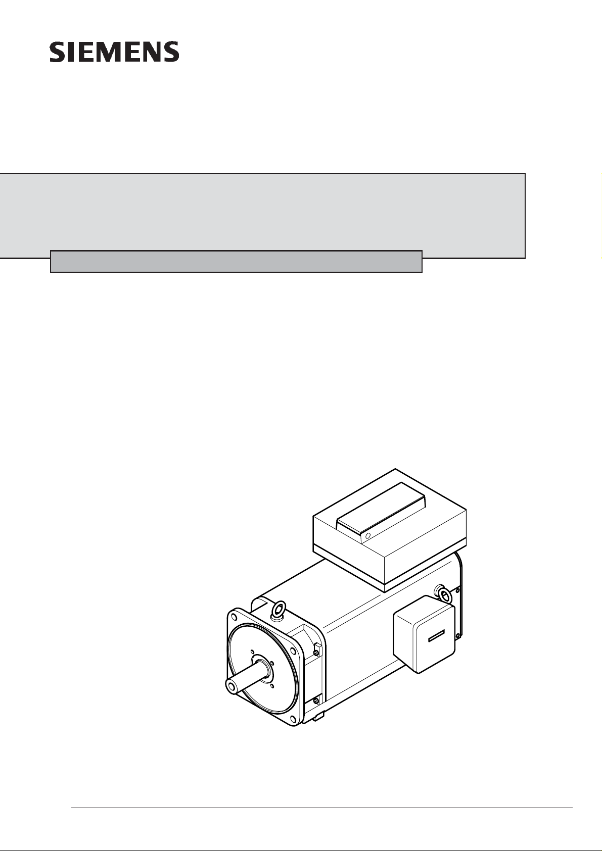
Hollow Shaft Motors 1PM6
Air cooled
Instructions Edition 12 / 2005
Hohlwellenmotoren 1PM6, luftgekühlt
Moteurs 1PM6 à arbres creux, à refroidissement par air
Motores de árbol hueco 1PM6, refrigerado por aire
Motori con albero cavo 1PM6, refrigerato ad aria
610.40 037.31
Siemens AG
1
Page 2
ENGLISH
Contents Page
Safety Giudelines........................................................... 2
1 Basic requirements ....................................................... 3
2 Product information ...................................................... 3
2.1 Application range ............................................................. 3
2.2 Technical parameters ...................................................... 3
2.3 Mode of operation and design ......................................... 3
2.4 Transport, Storage........................................................... 3
3 Fitting the motor ............................................................ 4
3.1 Basic requirements .......................................................... 4
3.2 Immited vibrations, output elements ............................... 4
3.3 Electrical connections ...................................................... 5
4 Start-up ........................................................................... 5
5 Repair .............................................................................. 5
5.1 Temperature sensor ........................................................ 5
5.2 Disassembly, assembly of gear encoder GEL 244......... 5
5.3 Changing bearings, lubrication ........................................ 6
Annex ...................................................................................... 27
Safety Giudelines
This manual contains notes which you should observe to ensure your own personal safety, as well to protect the product and connected
equipment. These notices are highlighted in the manual by a warning triangle and are marked as follows to the level of danger.
DANGER
indicates an imminently hazardous situation which, if not avoided,
will result in death or serious injury.
WARNING
indicates a potentially hazardous situation which, if not avoided,
could result in death or serious injury.
Symbol
Symbol
DANGER
DANGER
G E F A H R
Note on hazardous situation
WARNING
Warning note
CAUTION
used with the safety alert symbol indicates a potentially hazardous
situation which, if not avoided, may result in minor or moderate
injury.
CAUTION
used without safety alert symbol indicates a potentially hazardous
situation which, if not avoided, may result in property damage.
NOTICE
NOTICE used without safety alert symbol indicates a potential
situation which, if not avoided, may result in an undesirable result
or state.
Symbol
CAUTION
Warning note
CAUTION
Warning note
NOTICE
Note
Qualified Personnel
The device/system may only be set up and operated in conjunction with this manual. Only qualified personnel should be allowed to install
and work on the this equipment. Qualified persons are defined as persons who are authorized to commission, to ground, and to bag
circuits, equipment, and systems in accordance with established safety practices and standards.
Warning
This device and its components may only be used for the applications described in the catalogue or technical description, and only in
connection with devices or components from other manufacturers which have been approved or recommended by Siemens.
This product can only function correctly and safely if it is transported, stored, set up, and installed correctly, and operated and maintained
as recommended.
Copyright Siemens AG 2005 All rights reserved
The reproduction, transmission or use of this document or its
contents is not permitted without express written authority.
Offenders will be liable for damages. All rights, including rights
created by patent grant or registration of a utility model or design,
are reserved.
Siemens AG
Automation Group
Motion Control Systeme (MC)
D-97615 Bad Neustadt / Saale
2
Disclaimer of Liability
We have checked the contents of this manual for agreement with
hardware and software described. Since deviations cannot be
precluded entirely, we cannot guarantee full agreement. However,
the data in the manual are reviewed regularly and any necessary
corrections included in subsequent editions. Suggestions for
improvement are welcomed.
© Siemens AG 2005
Technical data subject to change.
Siemens AG
Page 3
ENGLISH
1 Basic requirements
1PM6 hollow shaft motors conform with:
- 98/37/EC Machine Directive
- 73/23/EEC Low Voltage Directive and
- 89/336/EEC Electromagnetic Compatibility Directive.
Ensure that your end product conforms to all currently valid
legal requirements. Follow the compulsory national, local and
installation-specific regulations.
Starting up the motors is not permitted until the end product
conforms to this stipulations of the named guidelines.
Observe the SIEMENS Project Planning Instructions for 1PM6 motors.
The safety instructions must be observed during the transport,
storage, assembly, disassembly and operation of the hollow
shaft motors!
Failure to observe the instructions can lead to serious personal
injuries or property damage.
All activities (transport, storage, assembly, disassembly of the
hollow-shaft motors) must be performed by qualified, skilled
workers who are aware of the specific dangers and who
observe the stipulations of the present operating instructions.
Maintenance (replacement of the gear encoder or bearing) may
only be performed by the manufacturer or authorized SIEMENS
service centers.
Mechanical hazards
Appropriate tools etc. are used for transport and assembly work
Lifting devices, ground conveyors and lifting tackle must
correspond to the valid regulations, e.g.:
EU Directive for Machines 98/37 EC, appendix 1
Regulations of the statutory industrial accident insurance institution
BGV D6, BGV D8, BGV D27, VBG 9a ecc.
There is an injury hazard in the vicinity of the rotating motor.
The manufacturer of the end product is responsible for
protection against accidental contact with the rotating motor.
Do not wear any additional clothing, jewelry or allow long hair
to hang freely.
Electrical hazards
The electrical connection to the hollow shaft motors is made as
described in the operating instructions.
All electrical work only must be performed by qualified
electricians and always with the equipment electrically dead.
Requirements of qualified electricians according to
EN 50110-1:1996 (DIN VDE 0105-100):
- Knowledge of electrical engineering
- Experience of electrotechnical work
- Knowledge of the plant / machine
- Knowledge of the hazards and safety measures
- Ability to decide upon a safe working sequence.
Hollow-shaft motors are only driven with configured converters. Any
other connection can lead to their destruction.
Never connect the motors directly to an external three-phase
mains! The correct phase sequence is vital.
The temperature sensor and encoder system including electronics
contain electrostatically endangered components (EEC).
Do not touch the connections with your hands or with tools
which could be electrostatically charged!
Site altitude: of up to 1000 m a.s.l.
The conditions at the location of use must correspond to all the
information on the rating plate.
It is forbidden to use them in areas at risk of explosion.
The operating instructions are part of the scope of delivery and
shall be kept in an accessible place.
The technical details of special versions and design variants of
the motors can vary.
Please contact the manufacturer or a SIEMENS service center if
you have any questions regarding the use or operational
characteristics of the motors.
2 Product information
2.1 Application range
The hollow shaft of the motor serves for the supply of cooling
lubricant or the insertion of collets. The motors are used when the
environmental conditions enable the use of air cooling.
Application cases: Milling machines with full encapsulation, turning
lathes with driven tools or counterspindles.
2.2 Technical parameters
Motor types 1PM6 101, 103, 105, 107
Types of construction Fig. 1
PM1 hollow-shaft motors are optionally fitted with either radial
ventilation or axial ventilation.
Standard protection class IP54
Ambient temperature max. 40oC
Measuring-surface sound-pressure level (EN 21 680 Part 1)
Balancing as per EN 60034-14 vibration severity grade SR
The bearings are designed for high speeds:
Motor types Standard L37
1PM6101...105 12.000 min
1PM6107 12.000 min
1PM6133 10.500 min
1PM6137 10.500 min
1PM6138 10.500 min
2.3 Mode of operation and design
Motors of the 1PM6 series are water-cooled, four-pole
asynchronous motors. The squirrel-cage rotor (rotor) has a
hollow shaft.
Main subassemblies
- Core-and-winding assembly
Temperature sensor for temperature measurement and regulation,
and to protect against overheating, fitted in the stator winding (a
second sensor as a reserve).
- Encoder system
Incremental encoder sin/cos (I-256) for measuring the motor
speed and the relative change in the rotor position (installed at the
ND-end).
- Separate fan set 2CW83..
according to figs. 2.1 and 2.2 (three-phase, external-rotor motor),
arranged axially or radially (top or on the side).
1PM6 133, 135, 137, 138
approx. 70 dB(A);
72 dB(A) with L37
-1
-1
-1
-1
-1
18.000 min
15.000 min
15.000 min
13.000 min
12.000 min
-1
-1
-1
-1
-1
Thermal hazards
The surface temperature of the motors may exceed 80oC (176oF).
Do not touch hot surfaces!
Temperature-sensitive components (electric lines, electronic
components) must not touch hot surfaces.
Intended Usage
The motors correspond to the harmonized standards of the
EN 60034 (VDE 0530) series.
They are intended for industrial or commercial plants.
Special case: More stringent requirements must be taken into
consideration during the configuration and assembly for use in noncommercial plants.
Usage for the intended purpose includes observing all the
specifications in the operating instructions.
Ambient temperatures: -15oC to +40oC (5oF to 104oF).
Siemens AG
2.4 Transport, Storage
WARNING
Danger during lifting and transporting
procedures.
Improper handling, unsuitable or defective
devices, tools etc. can cause injuries and/or
property damage.
Lifting devices, floor conveyors and lifting tackle
must conform to the currently valid regulations.
All the lifting eye-bolts provided (Fig. 2) should be used during
transport. Do not attach any additional loads.
Examples of standards: EU Directive for Machines 98/37 EC,
appendix 1.
3
Page 4
ENGLISH
Regulations of the statutory industrial accident insurance
institution BGV D6, BGV D8, BGV D27, VBG 9a.
Store in a dry, low-dust and low-vibration place
(v
< 0,2 mms-1).
eff
3 Fitting the motor
3.1 Basic requirements
- Take note of and observe the information on the rating plate
(model, degree of protection), and warning and informative
notices on the motor.
- Observe the permitted transverse and axial forces as stated in
the project planning instructions.
- Check for compliance with the conditions at the assembly site.
- If lifting eye-bolts have been screwed in, they must be either
tightened or removed after the motor has been installed.
- Motors are intended for either horizontal or vertical installation
(see fig. 1).
In the case of deviation from the intended installation, consult
the manufacturer in advance and state the type designation and
serial number.
- The inflow and outflow of cooling air must be unimpeded.
Maintain the minimum distance s shown in fig. 4 between the air
inlets and outlets, and other components. Do not take heated
outgoing air in again.
- Remove any transportation securing devices and keep them in a
safe place.
- Measure the insulating resistance. Dry the winding if the values
are < 1 kΩ per volt of rated voltage.
- Place it on evenly, ensure that base or flange are well tightened,
avoid distortions.
- Turn the rotor by hand. If grinding noises occur, eliminate the
cause or contact the manufacturer.
- Avoid impermissible loads.
Assemble without hitting or putting pressure on the shaft end.
- The covers which were removed in order to screw the motor tight
(6.83, fig. 2) must be re-fitted before the motor is started up.
3.2 Immited vibrations, output elements
Safety rules for working in electrical installations according to EN
50110-1:1996 (DIN VDE 0105-100):
- De-energize before starting work
- Isolate from electrical supply
- Secure against switching on again
- Check electrical deadness
- Earth and short-circuit
- Cover or cordon off adjacent parts which are electrically live
- Release for work
Connect the PE conductor to terminal .
Assembly requirements
- Proper installation is the responsibility of the manufacturer of the
system / machine.
- Connect the motor according to the wiring diagram in the
terminal box, and observe the data on the rating plate while
doing so.
- Adapt the connecting leads to the type of application and to the
anticipated voltages and current intensities.
- If the motor is supplied by means of converters, high-frequency
current and voltage oscillations in the motor supply leads may
cause electromagnetic interference.
Only use shielded power and signal leads.
Observe the EMC instructions of the converter manufacturer.
- The connecting leads are to be equipped with a strain relief
device and the devices which protect against rotation and
transverse forces, and must be prevented from kinking.
Power terminal
CAUTION
Warning of motor damage!
Connecting the motor directly to a three-phase system will
destroy it.
Motors may only be driven with configured converters.
Ensure that the phase sequence is correct.
The gear encoder and temperature sensor are electrostatically
endangered components (EEC).
Do not touch the connections with your hands or with tools which
could be electrostatically charged!
WARNING
Hazard from rotating rotor!
Provide the output elements with protection against
accidental contact.
1PM6 hollow shaft motors are not fitted with a feather key as
standard.
The system’s vibrational behavior on site is affected by output
elements, the mounting conditions, the alignment, the installation
and external vibrations. This can change the vibration values of the
motor.
In the interests of reliable operation and a long bearing service life,
the vibration values specified in fig. 8 should not be exceeded.
If necessary, fully balance the rotor with the output elements
according to ISO 1940.
Suitable devices should always be used to push on or pull off the
output elements (e.g. the coupler disk, gear wheel).
As standard, the rotors are designed with a smooth shaft end, and
are balanced dynamically.
3.3 Electrical connections
D A N G E R
Electric shock hazard!
Only use qualified, skilled personnel.
Observe the regulations for working in
electrotechnical plants.
1. The ends of the leads must not be stripped further than
necessary, i.e. the insulation must extend to the cable lug,
terminal or wire-end sleeve.
2. Match the size of the cable lugs or wire-end sleeves to the
dimensions of the terminal board connections and to the crosssection of the power lead, lay parallel connecting leads if
necessary.
3. The cable lugs of the power terminals must rest directly on the
cable lugs of the motor winding.
4. Connect the PE conductor.
5. The inside of the terminal box must be kept clean and free from
cable residues and moisture.
6. For permanently secure joints, the screws and bolts of the
electrical connections (except the terminal blocks) must be
tightened to the torques specified in fig. 7.
7. The minimum air gaps specified in fig. 6 must be observed, both
when connecting and when re-arranging internal connecting
leads. Maintain minimum air gaps of 5.5 mm from live, noninsulated parts. Avoid protruding wire ends.
8. Any entries which are not in use must be sealed dust and water-
tight, and the sealing elements must be screwed in firmly and
tightly.
9. Check the seals and sealing surfaces of the terminal box to
ensure that the degree of protection is maintained.
Pulse encoder and temperature sensor
- Connect with contact pins via the flanged socket fitted in the
terminal box.
Separate fan set 2CW83.. (radial fan 7.00, Fig.2.1)
1. Note the markings on the rating plate (7.32) and the
circuit diagram in the terminal box of the unit (7.01).
2. Connect the PE conductor to terminal .
3. Check the direction of rotation at the casing air inlet (directional
arrow).
4
Siemens AG
Page 5
ENGLISH
4 Start-up
CAUTION
Thermal hazard from hot surfaces!
The surface temperatures of the motors may
exceed 80
surfaces! Protection must be provided
against accidental contact if necessary.
Temperature-sensitive components (electric lines,
electronic components) must not
touch hot surfaces.
Checks before starting up
1. Turn the rotor by hand, the rotor must not grind.
2. Check the mounting of the motor and its alignment.
3. Check the direction of rotation in the uncoupled state.
4. Check the suitability and setting of the output elements for the
intended conditions of use.
5. Check the electrical connections: design, tightening torques
according to specification.
6. Check the PE conductor connection.
7. Check the functional condition of the auxiliary devices present.
8. Check the protection against accidental contact with moving
and live parts.
9. Check the functional condition and „on state“ of the separate fan
set.
NOTE
The limit speed n
permissible peak operating speed. Higher speeds are not
permitted.
Perform additional checks if necessary.
If deviations from normal operation occur, e.g. increased
temperature, sound emission or vibrations, switch the motor off and
find the cause. Consult the manufacturer or SIEMENS service
center if necessary.
Do not disable the protective devices, even in trial operation.
The separate fan set must be in continual operation. Keep the air
inlets and outlets clear.
o
C (176oF). Do not touch hot
(see rating plate) is the maximum
max
5 Repair
NOTE
Maintenance (replacement of the encoder or bearing) may only
be performed by the manufacturer or authorized SIEMENS
service centers.
5.1 Temperature sensor
D A N G E R
Electric shock hazard!
Observe all the instructions in section 3.3.
Switch off all additional and auxiliary circuits when
isolating.
Do not reverse these measures until the
maintenance has been completed and the motor has
been completely assembled.
Observe the following additional requirements:
- Ground the work place.
- Touch a conductive, grounded object before making contact.
An electrostatic charge must not be transferred on contact.
- Do not touch the plug pins directly.
- Use suitable packaging, e.g. corrugated cardboard boxes or
conductive plastic bags (not ordinary plastic bags or polystyrene).
Disassembly (Fig.2)
1. Unscrew the screws (6.92) and remove the cover (6.91) or
dismount the ventilation unit axially with the intermediate casing
(7.40). Remove the GAMMA ring (6.96) or in the case of L37
balancing disc. Mark the position!
2. Unscrew the screws (8.58) and remove the cover together with
seal or O-ring.
3. Mark the position of the encoder wheel (8.50) on the shaft.
4. Remove the encoder wheel with a suitable tool.
5. In the terminal box, remove the shrink tubing from the adapter
plug, disconnect the adapter plug from the encoder lead.
6. Disconnect the shielded lead of the encoder from the terminal
box pedestal
7. Unscrew the strain relief clamp from the non-drive end shield.
8. Unscrew the screws (8.53), remove the encoder (8.51) from the
slot, and pull the encoder lead through the non-drive
end shield.
Assembly (Fig.2)
CAUTION
Damage to the encoder and encoder wheel.
Assemble carefully. The encoder and wheel must not be
touching when assembled. Observe the operating instructions
for the encoder.
The gap between the encoder wheel (8.50) and encoder (8.51) is
set with a 0.2 mm feeler gage.
The gage and operating instructions are part of the scope of
delivery.
1. Slide the head of the encoder radially outwards in the non-drive
endshield until it meets the stop, tighten the screws (8.53) with a
torque of 2 Nm.
2. Attach the encoder lead to the non-drive end shield with a strain
relief clamp.
3. Connect the adapter plug of the encoder lead to the flange
connector in the terminal box.
4. Secure the plug connection with shrink tubing.
5. Lay a shielded lead from the encoder to the terminal box screw.
6. Heat the encoder wheel (8.50) to approx. 1500C (3020F) and
slide onto the shaft up to the stop. Set clearance!
7. Grease the O-ring before fitting. Secure the cover (8.56),
together with sealing ring or O-ring, with screws (8.58).
8. Slide on the GAMMA ring (6.96) up to the press on distance
(fig.2). The L37 has no lip seal.
9. Attach the cover (6.91) with screws (6.92) and spring ring
(6.93), or screw the ventilation unit on axially and screw on the
intermediate casing with screws (7.41 and 7.06). Shrink on the
balancing disc, maintain clearance (Fig. 2)!
If the temperature sensor fails, one can switch to the reserve
temperature sensor.
Switch over in the terminal box, paying attention to the wiring
diagram in the terminal box.
5.2 Disassembly, assembly of encoder
CAUTION
Damage to the encoder.
Encoder systems with integrated electronics and temperature
sensors are electrostatically endangered components.
Do not touch the connections with your hands or with tools
which could be electrostatically charged!
Siemens AG
5.3 Changing bearings, lubrication
Bearing replacement intervals
Bearing replacement intervals t
according to fig. 9.1.
It is recommended to replace the bearings at the drive and nondrive ends after reaching the stated operating hours, or after
three years at the latest. The values t
- Horizontal fitting
- Maximum cooling air temperature +30°C (860F)
- Maximum bearing temperature +85°C (1850F)
- Max. speed in continuous operation is 75% of the limit speed
n
. Estimate the mean operating speed nm if the motor speed
max.
varies.
for normal operating conditions
LW
apply to:
LW
5
Page 6

ENGLISH
- Vibrations with vibration severity grade SR according to
EN 60034-14.
The bearing replacement intervals t
under more severe conditions, e.g. vertical fitting, operating above
75 % of the limit speed n
frequent reverse operation etc.
The value t
which the bearing temperature exceeds +85°C (1850F).
must be halved for each additional 15°C (590F) by
LW
., high vibration and impact loads,
max
Disassembly
1. Mark the original positions of the parts in relation to one another
(e.g. with a marker pen or a scribing iron) in order to simplify the
re-assembly procedure.
2. Fit the encoder according to 5.2.
3. Unscrew the screws out of the bearing cover and end shield on
the drive end, carefully remove the drive end shield.
4. Pull the rotor out of the motor stator.
5. Pull off the rolling contact bearings using a suitable device (see
Fig. 10.1). Do not re-use the rolling contact bearings after they
have been pulled off.
Assembly
The bearings of the hollow-shaft motors, the standard design is
deep groove ball bearings eep groove ball bearing with plastic
bearing cage(1.60 and 6.10, fig. 2).
Hybrid spindle bearings are used in option L37.
NOTE!
Recommendations for replacing the bearings:
Obtain the bearings from the motor manufacturer (deep
groove ball bearing with special bearing clearance. In the
case of the L37, the hybrid spindle bearings are in a ><
arrangement).
Always replace the full set of sealing elements (radial shaft
seal, GAMMA rings).
L37 without WDR, without Gamma ring.
Ensure absolute cleanliness when changing the bearings.
are reduced by up to 50%
LW
1. Do not wash out the bearing before greasing.
Half fill the grease compartments (end shield, bearing cover)
with grease (see fig. 10.2).
Grease types: LUBCON THERMOPLEX2TML (from Lubricant
Consult)
Quantity of grease per bearing: see Fig. 9.2, spread the grease
evenly over the raceway.
2. Heat the rolling contact bearings inductively to between 800C to
1000C (1760F to 2120F) and push them on.The inner bearing
ring must be flush with the shaft shoulder. Do not hit hard.
3. Position the rotor inside the casing.
4. Check the bearing cover seals, replace if necessary.
5. Insert the drive end shield centrally into the motor casing
without canting it.
6. Tighten the screws in the bearing cover. Screw the drive end
shield up tightly. Tightening torques as shown in fig. 7.
7. Mount the encoder system according to 5.2.
Bearing run-in
Bearings need a running-in time under low load. To do this, run the
motors continuously up from 0 to 75% of the limit speed n
period of 20 minutes.
max
over a
In the case of the L37, repeat several times (3 or 4 times).
6
Siemens AG
Page 7
DEUTSCH
Inhalt Seite
Sicherheitstechnische Hinweise.................................. 7
1 Grundlegende Anforderungen ..................................... 8
2 Angaben zum Erzeugnis ............................................... 8
2.1 Anwendungsbereich ........................................................ 8
2.2 Technische Kennwerte .................................................... 8
2.3 Arbeitsweise, Aufbau ....................................................... 8
2.4 Transport, Lagerung ........................................................ 8
3 Motormontage ................................................................ 9
3.1 Grundlegende Anforderungen ........................................ 9
3.2 Immitierte Schwingungen, Abtriebselemente ................. 9
3.3 Elektrischer Anschluss .................................................... 9
4 Inbetriebnahme .............................................................. 10
5 Instandhaltung ............................................................... 10
5.1 Temperatursensor ........................................................... 10
5.2 Demontage, Montage Zahnradgeber GEL 244 ............... 10
5.3 Lagerwechsel, Schmierung ............................................. 11
Anhang.................................................................................... 27
Sicherheitstechnische Hinweise
Diese Betriebsanleitung enthält Hinweise, die Sie zu Ihrer persönlichen Sicherheit sowie zur Vermeidung von Sachschäden beachten
müssen. Die Hinweise zu Ihrer persönlichen Sicherheit sind durch ein Warndreieck hervorgehoben, Hinweise zu alleinigen Sachschäden
stehen ohne Warndreieck. Je nach Gefährdungsgrad werden sie folgendermaßen dargestellt:
Piktogramm
Piktogramm
Piktogramm
GEFAHR
G E F A H R
Gefahrenhinweis
WARNUNG
Warnhinweis
VORSICHT
Warnhinweis
VORSICHT
Warnhinweis
ACHTUNG
Hinweis
GEFAHR
bedeutet, dass Tod, schwere Körperverletzung oder erheblicher
Sachschaden eintreten werden, wenn die entsprechenden
Vorsichtsmaßnahmen nicht getroffen werden.
WARNUNG
bedeutet, dass Tod oder schwere Körperverletzungen eintreten
können, wenn die entsprechenden Vorsichtsmaßnahmen nicht
getroffen werden.
VORSICHT
mit Warndreieck bedeutet, dass eine leichte Körperverletzung
eintreten kann, wenn die entsprechenden Vorsichtsmaßnahmen
nicht getroffen werden.
VORSICHT
ohne Warndreieck bedeutet, dass ein Sachschaden eintreten kann,
wenn die entsprechenden Vorsichtsmaßnahmen nicht getroffen
werden.
ACHTUNG
bedeutet, dass ein unerwünschtes Ereignis oder Zustand eintreten
kann, wenn der entsprechende Hinweis nicht beachtet wird.
Qualifiziertes Personal
Inbetriebsetzung und Betrieb des Gerätes dürfen nur von qualifiziertem Personal vorgenommen werden. Qualifiziertes Personal im Sinne
der sicherheitstechnischen Hinweise dieser Betriebsanleitung sind Personen,
die die Berechtigung haben, Geräte, Systeme und Stromkreise gemäß den Standards der Sicherheitstechnik in Betrieb zu nehmen, zu
erden und zu kennzeichnen.
Warnung
Das Gerät darf nur für die im Katalog und in der Projektierungsanleitung vorgesehenen Einsatzfälle und nur in Verbindung mit von
Siemens empfohlenen bzw. zugelassenen Fremdgeräten und -komponenten verwendet werden.
Der einwandfreie und sichere Betrieb des Produktes setzt sachgemäßen Transport, sachgemäße Lagerung, Aufstellung und Montage
sowie sorgfältige Bedienung und Instandsetzung voraus.
Copyright Siemens AG 2005 All rights reserved
Weitergabe sowie Vervielfältigung dieser Unterlage, Verwertung
und Mitteilung ihres Inhalts ist nicht gestattet, soweit nicht
ausdrücklich zugestanden. Zuwiderhandlungen verpflichten zum
Schadenersatz.
Alle Rechte vorbehalten, insbesondere für den Fall der
Patenterteilung oder GM-Eintragung.
Siemens AG
Bereich Automatisierungs- und Antriebstechnik
Geschäftsgebiet Motion Control Systeme (MC)
D-97615 Bad Neustadt an der Saale
Siemens AG
Haftungsausschluss
Wir haben den Inhalt der Druckschrift geprüft. Dennoch können
Abweichungen nicht ausgeschlossen werden, so dass wir für die
vollständige Übereinstimmung keine Gewähr übernehmen. Die
Angaben in dieser Druckschrift werden regelmäßig überprüft, und
notwendige Korrekturen sind in den nachfolgenden Auflagen
enthalten.
Für Verbesserungsvorschläge sind wir dankbar.
© Siemens AG 2005
Technische Änderungen bleiben vorbehalten.
7
Page 8
DEUTSCH
1 Grundlegende Anforderungen
Für Hohlwellenmotoren 1PM6 besteht Konformität mit:
- 98/37/EG Maschinenrichtlinie
- 73/23/EWG Niederspannungsrichtlinie
- 89/336/EWG Richtlinie über die elektromagnetische Verträglichkeit.
Sichern Sie für Ihr Endprodukt die Einhaltung aller bestehenden
Rechtsvorschriften! Beachten Sie die verbindlichen nationalen,
örtlichen und anlagenspezifischen Vorschriften!
Die Inbetriebnahme der Motoren ist so lange untersagt, bis das
Endprodukt die Bestimmungen der genannten Richtlinien
erfüllt.
Beachten Sie die SIEMENS-Projektierungsanleitung für 1PM6-Motoren!
Für Transport, Lagerung, Montage, Demontage und Betrieb
der Hohlwellenmotoren müssen die Hinweise zur Sicherheit
beachtet werden!
Das Nichteinhalten kann schwere Körperverletzungen oder
Sachschäden bewirken.
Alle Tätigkeiten (Transport, Lagerung, Montage, Demontage
der Hohlwellenmotoren) dürfen nur durch qualifizierte
Fachkräfte ausgeführt werden, die die besonderen Gefahren
kennen und die Festlegungen der vorliegenden Betriebsanleitung einhalten.
Die Instandhaltung (Wechsel der Zahnradgeber oder Lager) erfolgt
nur durch den Hersteller oder autorisierte SIEMENS-Servicezentren.
Mechanische Gefährdungen
Für Transport- und Montagearbeiten werden geeignete Hilfsmittel
benutzt.
Hubgeräte, Flurförderzeuge und Lastaufnahmemittel müssen
den geltenden Vorschriften entsprechen, z.B:
EWG-Richtlinie für Maschinen 98/37 EG, Anhang 1
Berufsgenossenschaftliche Vorschriften BGV D6, BGV D8,
BGV D27, VBG 9a u.a.
In der Nähe des rotierenden Motors besteht Verletzungsgefahr.
Der Hersteller des Endproduktes ist für den Berührungsschutz des
rotierenden Motors zuständig.
Tragen Sie keine weite Kleidung, Schmuck oder lange offene
Haare!
Elektrische Gefährdungen
Der elektrische Anschluss der Hohlwellenmotoren erfolgt nach den
Angaben der Betriebsanleitung.
Alle Elektroarbeiten werden nur im spannungslosen Zustand
durch eine Elektrofachkraft ausgeführt.
Anforderungen an die Elektrofachkraft nach EN 50110-1:1996
(DIN VDE 0105-100):
- Kenntnisse der Elektrotechnik
- Erfahrungen mit elektrotechnischen Arbeiten
- Kenntnisse der Anlage / Maschine
- Kenntnisse der Gefährdungen und Sicherheitsmaßnahmen
- Fähigkeiten zu Entscheidungen zum sicheren Arbeitsablauf.
Bestimmungsgemäßer Gebrauch
Die Motoren entsprechen den harmonisierten Normen der Reihe
EN 60034 (VDE 0530).
Sie sind für industrielle oder gewerbliche Anlagen bestimmt.
Sonderfall: Für den Einsatz in nicht gewerblichen Anlagen bei
Projektierung und Montage erhöhte Anforderungen berücksichtigen!
Das Einhalten aller Vorgaben der Betriebsanleitung ist Bestandteil
der bestimmungsgemäßen Verwendung.
Umgebungstemperaturen: -15
o
C bis +40oC (5oF bis 104oF).
Aufstellungshöhe: Maximal 1000 m über NN.
Die Bedingungen am Einsatzort müssen allen Angaben des
Leistungsschildes entsprechen.
Der Einsatz in explosionsgefährdeten Bereichen ist verboten.
Die Betriebsanleitung ist Bestandteil des Lieferumfangs und ist
zugänglich aufzubewahren.
Sonderausführungen und Bauvarianten der Motoren können in
technischen Details abweichen.
Wenden Sie sich an den Hersteller oder ein SIEMENS-Servicezentrum, wenn zu Einsatz oder Betriebsverhalten der Motoren
Fragen bestehen!
2 Angaben zum Erzeugnis
2.1 Anwendungsbereich
Die Hohlwelle des Motors dient dem Zuführen von Kühlschmiermittel oder der Durchführung von Spannwerkzeugen. Die
Motoren werden eingesetzt, wenn die Umgebungsbedingungen
den Einsatz der Luftkühlung gestatten.
Anwendungsfälle: Fräsmaschinen mit Vollkapselung, Drehmaschinen mit angetriebenen Werkzeugen oder Gegenspindeln.
2.2 Technische Kennwerte
Motorentypen 1PM6 101, 103, 105, 107
Bauformen Fig. 1
Hohlwellenmotoren 1PM6 sind wahlweise mit Belüftung radial oder
Belüftung axial ausgeführt.
Standardschutzart IP54
Umgebungstemperatur max. 40oC (78°F)
Messflächenschalldruckpegel nach EN 21 680 Teil 1
Wuchtung nach EN 60034-14 Schwingstärke-Stufe SR
Die Lager sind ausgelegt für hohe Drehzahlen:
Motortypen Standard L37
1PM4101...105 12.000 min
1PM4107 12.000 min
1PM4133 10.500 min
1PM4137 10.500 min
1PM4138 10.500 min
1PM6 133, 135, 137, 138
ca. 70 dB(A); mit L37 72 dB(A)
-1
-1
-1
-1
-1
18.000 min
15.000 min
15.000 min
13.000 min
12.000 min
-1
-1
-1
-1
-1
Hohlwellenmotoren werden nur mit den projektierten Umrichtern betrieben. Davon abweichender Anschluss kann zur Zerstörung führen.
Schließen Sie niemals die Motoren direkt an ein fremdes
Drehstromnetz an! Beachten Sie die richtige Phasenfolge!
Temperatursensor und Gebersystem mit integrierter Elektronik sind
elektrostatisch gefährdete Bauteile (EGB).
Berühren Sie nicht die Anschlüsse mit den Händen oder mit
Werkzeugen, die elektrostatisch aufgeladen sein können!
Thermische Gefährdung
Die Oberflächentemperaturen der Motoren können über 80oC
(176oF) betragen.
Berühren Sie nicht heiße Oberflächen!
Temperaturempfindliche Bauteile (elektrische Leitungen, elektronische Bauteile) dürfen nicht an heißen Oberflächen anliegen.
8
2.3 Arbeitsweise, Aufbau
Motoren der Baureihe 1PM6 sind luftgekühlte vierpolige Asynchronmaschinen. Der Käfigläufer (Rotor) besitzt eine Hohlwelle.
Hauptbaugruppen
- Motoraktivteil
Temperatursensor zur Temperaturmessung und Regelung
sowiezum Schutz gegen unzulässige Erwärmung, eingebaut in
der Ständerwicklung (ein zweiter Sensor als Reserve).
- Gebersystem
Inkrementalgeber sin/cos (I-256) zum Bestimmen von Motordrehzahl und relativer Änderung der Läuferlage (auf der B-Seite).
- Fremdlüfteraggregat 2CW83..
nach Fig. 2.1 und 2.2 (Drehstromaußenläufermotor),
angeordnet axial oder radial (oben oder seitlich).
Siemens AG
Page 9
DEUTSCH
2.4 Transport, Lagerung
WARNUNG
Gefährdung bei Hebe- und Transportvorgängen!
Unsachgemäße Ausführung, ungeeignete oder
schadhafte Geräte und Hilfsmittel können
Verletzungen und/oder Sachschäden bewirken.
Hubgeräte, Flurförderzeuge und Lastaufnah-memittel
müssen den Vorschriften entsprechen.
Für den Transport alle vorhandenen Hebeösen (Fig. 2) benutzen.
Keine zusätzlichen Lasten anbringen.
Beispiele für Standards: EWG-Richtlinie für Maschinen 98/37/EG,
Anhang 1,
Berufsgenossenschaftliche Vorschriften BGV D6, BGV D8, BGV
D27, VBG 9a.
Die Lagerung erfolgt im trockenen, staub- und schwingungsarmen
(v
< 0,2 mms-1) Raum.
eff
3 Motormontage
3.1 Grundlegende Anforderungen
- Angaben des Leistungsschildes (Bauform, Schutzart) und Warnund Hinweisschilder am Motor beachten.
- Zulässige Quer- und Axialkräfte nach Projektierungsanleitung
einhalten.
- Übereinstimmung mit den Bedingungen am Montageort prüfen.
- Eingeschraubte Hebeösen nach dem Aufstellen fest anziehen
oder entfernen.
- Motoren sind für horizontale oder für vertikale Aufstellung
vorgesehen (siehe Fig. 1).
Bei Abweichung von der vorgesehenen Aufstellung vorher den
Hersteller konsultieren mit Angabe von Typbezeichnung und
Fertigungsnummer.
- Kühlluft muss ungehindert zu- und abströmen. Mindestabstand s
der Zu- und Abluftöffnungen zu anderen Bauteilen nach
Fig. 4 einhalten. Erwärmte Abluft nicht wieder ansaugen.
- Transportsicherungen, sofern vorhanden, entfernen und
aufbewahren.
- Isolationswiderstand messen. Bei Werten< 1 kΩ je Volt
Bemessungspannung Wicklung trocknen.
- Gleichmäßige Auflage, gute Fuß- oder Flanschbefestigung
beachten, Verspannungen vermeiden.
- Läufer von Hand drehen. Bei möglichen Schleifgeräuschen die
Ursache beseitigen oder den Hersteller konsultieren.
- Unzulässige Belastungen vermeiden.
Montage ohne Druck und Schläge auf das Wellenende ausführen.
- Die zum Festschrauben des Motors abgenommenen Deckel
(6.83, Fig. 2) müssen vor Inbetriebnahme wieder montiert
werden.
3.2 Immittierte Schwingungen, Abtriebselemente
WARNUNG
Gefährdung durch rotierenden Läufer!
Sichern Sie die Abtriebselemente mit Berührungsschutz!
Hohlwellenmotoren 1PM6 besitzen keine Passfeder.
Das Schwingverhalten des Systems am Einsatzort wird beeinflusst
durch Abtriebselemente, Anbauverhältnisse, Ausrichtung, Aufstellung und Fremdschwingungen. Damit können sich die Schwingwerte des Motors ändern.
Als Voraussetzung für die sichere Funktion und lange Lagerlebensdauer Schwingwerte nach Fig.8 nicht überschreiten.
Bei Bedarf Läufer mit den Abtriebselementen nach ISO1940
komplett auswuchten.
Das Auf- und Abziehen von Abtriebselementen (z.B. Kupplungsscheibe, Zahnrad) nur mit geeigneten Vorrichtungen ausführen.
Standardmäßig sind die Läufer mit glattem Wellenende ausgeführt
und dynamisch ausgewuchtet.
3.3 Elektrischer Anschluss
GEFAHR
G E F A H R
Stromschlaggefahr!
Nur qualifizierte Fachkräfte einsetzen!
Vorschriften für Arbeiten in elektrotechnischen
Anlagen einhalten!
Sicherheitsregeln für das Arbeiten in elektrischen Anlagen
nach EN 50110-1:1996 (DIN VDE 0105-100):
- Nur im spannungslosen Zustand arbeiten
- Freischalten
- Gegen Wiedereinschalten sichern
- Spannungsfreiheit feststellen
- Erden und Kurzschließen
- Benachbarte, unter Spannung stehende Teile abdecken
oder abschranken
- Freigabe zur Arbeit
Schutzleiter an Klemme anschließen!
Montageanforderungen
- Sachgerechte Installation liegt in der Verantwortung des
Herstellers der Anlage / Maschine.
- Motor nach Schaltbild im Klemmenkasten anschließen, dabei
Daten des Leistungsschilds beachten.
- Anschlussleitungen der Verwendungsart, den auftretenden
Spannungen und Stromstärken anpassen.
- Bei Umrichterspeisung können hochfrequente Strom- und
Spannungsschwingungen in den Motorzuleitungen elektromagnetische Störungen bewirken.
Nur abgeschirmte Leistungs- und Signalleitungen verwenden.
EMV-Hinweise des Umrichterherstellers beachten.
- Anschlussleitungen mit Verdreh-, Zug- und Schubentlastung
sowie Knickschutz versehen.
Leistungsanschluss
ACHTUNG
Warnung vor Motorschäden!
Der direkte Anschluss an das Drehstromnetz führt zur Zerstörung
des Motors.
Motoren nur mit den projektierten Umrichtern betreiben.
Richtige Phasenfolge beachten!
Zahnradgeber und T emperatursensor sind elektrostatisch
gefährdete Bauteile (EGB).
Berühren Sie nicht die Anschlüsse mit den Händen oder
Werkzeugen, die elektrostatisch aufgeladen sein können!
1. Leitungsenden nur soweit abisolieren, dass die Isolierung bis
Kabelschuh, Klemme oder Aderendhülse reicht.
2. Größe der Kabelschuhe oder Aderendhülsen den Abmessungen
der Anschlüsse des Klemmbretts und dem Querschnitt der
Netzleitung anpassen, ggf. parallele Anschlussleitungen
verwenden.
3. Kabelschuhe der Leistungsanschlüsse müssen direkt auf den
Kabelschuhen der Motorwicklung aufliegen.
4. Schutzleiter anschließen.
5. Das Innere des Klemmenkastens muss sauber und frei von
Leitungsresten und Feuchtigkeit sein.
6. Schraubenverbindungen der elektrischen Anschlüsse (außer
Klemmenleisten) für dauerhaft sichere Verbindungen mit
Drehmomenten nach Fig.7 anziehen.
7. Beim Anschließen und beim Umsetzen der inneren
Verbindungsleitungen Mindestluftstrecken nach Fig.6 einhalten.
Mindestluftstrecken bei nicht isolierten unter Spannung
stehenden Teilen von 5,5 mm einhalten. Abstehende Drahtenden vermeiden.
8. Nicht benutzte Einführungen staub- und wasserdicht verschließen, Verschlusselemente fest und dicht einschrauben.
9. Dichtungen und Dichtflächen des Klemmenkastens prüfen,
damit die Schutzart eingehalten wird.
Siemens AG
9
Page 10
DEUTSCH
Impulsgeber und Temperatursensor
- Anschluss über die im Klemmenkasten eingebaute Flanschdose
mit Kontaktstiften herstellen.
Fremdlüfteraggregat 2CW83.. (Radiallüfter 7.00, Fig.2.1)
1. Angaben von Leistungsschild (7.32) und Schaltbild im
Klemmenkasten des Aggregats (7.01) beachten.
2. Schutzleiter an Klemme
3. Drehrichtung am Lufteintritt des Gehäuses (Richtungspfeil)
prüfen.
anschließen.
4 Inbetriebnahme
VORSICHT
Thermische Gefährdung durch heiße Oberflächen!
Die Oberflächentemperatur der Motoren kann
über 80oC (176oF) betragen.
Heiße Oberflächen nicht berühren!
Bei Bedarf Berührungsschutz vorsehen!
Temperaturempfindliche Bauteile (elektrische Leitungen, elektronische Bauteile) dürfen nicht
an heißen Oberflächen anliegen.
Prüfungen vor Inbetriebnahme
1. Läufer von Hand drehen, der Läufer darf nicht schleifen.
2. Montage des Motors und die Ausrichtung prüfen.
3. Drehrichtung im ungekuppelten Zustand kontrollieren.
4. Eignung und Einstellung der Abtriebselemente für die vorgese-
henen Einsatzbedingungen prüfen.
5. Prüfung der elektrischen Anschlüsse: Ausführung, Anziehdreh-
momente nach Vorschrift.
6. Schutzleiteranschluss prüfen.
7. Funktionsfähigkeit der Zusatzeinrichtungen, sofern vorhanden,
prüfen.
8. Berührungsschutzmaßnahmen der bewegten und
spannnungsführenden Teile prüfen.
9. Fremdlüfteraggregat auf Funktionsfähigkeit und Einschaltzu-
stand prüfen.
HINWEIS!
Die Grenzdrehzahl n
zulässige Betriebsdrehzahl. Höhere Drehzahlen sind nicht zulässig.
(siehe Leistungsschild) ist die höchste
max
5.1 Temperatursensor
Bei Ausfall des Temperatursensors kann auf den ReserveTemperatursensor umgeschaltet werden.
Umklemmen im Klemmenkasten, dabei Schaltbild im Klemmenkasten beachten!
5.2 Demontage, Montage Geber
VORSICHT
Beschädigung des Gebers!
Gebersysteme mit integrierter Elektronik und Temperatursensoren sind elektrostatisch gefährdete Bauteile.
Berühren Sie nicht die Anschlüsse mit den Händen oder mit
Werkzeugen, die elektrostatisch aufgeladen sein können!
Beachten Sie zusätzlich folgende Anforderungen:
- Arbeitsplatz erden.
- Vor Berühren leitfähigen geerdeten Gegenstand anfassen.
Durch Berühren keine elektrostatische Ladung übertragen.
- Steckerpins nicht direkt anfassen.
- Geeignete Verpackung verwenden, z.B. Schachtel aus Wellpap-
pe oder leitfähige Kunststoffbeutel (keine üblichen Kunststoffe
oder Polystyrol).
Demontage (Fig.2)
1. Schrauben (6.92) herausdrehen und Deckel (6.91) abnehmen
oder Belüftungseinheit axial mit Zwischengehäuse (7.40)
demontieren. GAMMA-Ring oder für L37 Tarierscheibe (6.96)
entfernen. Lage markieren.
2. Schrauben (8.58) herausdrehen und Deckel mit Dichtung oder
O-Ring abnehmen.
3. Position des Geberrads (8.50) auf der Welle markieren.
4. Geberrad mit geeignetem Werkzeug abziehen.
5. Im Klemmenkasten den Schrumpfschlauch vom Zwischenstekker entfernen, Zwischenstecker von der Geberleitung lösen.
6. Schirmleitung des Gebers vom Klemmenkasten-Sockel lösen.
7. Zugentlastungsschelle am Lagerschild der B-Seite abschrauben.
8. Schrauben (8.53) herausdrehen, Geber (8.51) herausnehmen
und Leitung des Gebers durch das Lagerschild B-Seite ziehen.
Montage (Fig.2)
Bei Bedarf weitere Prüfungen ausführen.
Bei Veränderungen gegenüber dem normalen Betrieb, z.B. erhöhte
Temperatur, Schallemission oder Schwingungen Motor abschalten
und Ursache ermitteln. Bei Bedarf Hersteller oder SIEMENSServicezentrum konsultieren.
Schutzeinrichtungen auch im Probebetrieb nicht außer Funktion
setzen.
Fremdlüfteraggregat muss ständig in Betrieb sein. Luftein- und
Austrittsöffnungen freihalten.
5 Instandhaltung
HINWEIS
Instandhaltung (Wechsel der Geber und Lager) erfolgt nur
durch den Hersteller oder autorisierte SIEMENSServicezentren.
G E F A H R
Stromschlaggefahr!
Beachten Sie alle Hinweise nach Punkt 3.3!
Beim Freischalten auch alle Zusatz- und
Hilfsstromkreise ausschalten.
Diese Maßnahmen erst dann zurücknehmen,
wenn die Instandhaltung abgeschlossen und der
Motor vollständig montiert ist.
VORSICHT
Schäden am Geber und Geberrad!
Führen Sie die Montage vorsichtig aus!
Geber und Rad dürfen sich nach Montage nicht berühren.
Beachten Sie die Betriebsanleitung des Gebers!
Der Abstand zwischen Geberrad (8.50) und Geber (8.51) wird mit
Montagelehre (Stärke 0,2 mm) eingestellt.
Lehre und Betriebsanleitung gehören zum Lieferumfang.
1. Kopf des Gebers (8.51) im Lagerschild B-Seite radial bis
Anschlag nach außen schieben, Schrauben (8.53) anziehen,
Anziehdrehmoment 2 Nm.
2. Geberleitung am Lagerschild B-Seite mit Zugentlastungsschelle
befestigen.
3. Zwischenstecker von Geberleitung und Flanschstecker im
Klemmenkasten zusammenstecken.
4. Steckverbindung mit Schrumpfschlauch sichern.
5. Schirmleitung des Gebers auf Klemmenkastenschraube legen.
6. Geberrad (8.50) auf ca. 1500C (3020F) erwärmen und bis
Anschlag auf die Welle fügen.
Abstand Geber - Geberrad einstellen!
7. O-Ring vor Montage einfetten. Deckel (8.56) mit Dichtring bzw.
O-Ring mit Schrauben (8.58) befestigen.
8. GAMMA-Ring (6.96) bis zum Aufdrückmaß (Fig. 2) aufschieben. Bei L37 Tarierscheibe aufschrumpfen.
Abstand (Fig. 2) einhalten.
9. Deckel (6.91) mit Schrauben (6.92) und Federring (6.93)
befestigen oder Belüftungseinheit axial und Zwischengehäuse
mit Schrauben (7.41 und 7.06) anschrauben.
10
Siemens AG
Page 11

DEUTSCH
5.3 Lagerwechsel, Schmierung
Lagerwechselfrist
Lagerwechselfristen t
Lagerwechsel auf A- und B-Seite wird empfohlen nach Erreichen
der angegebenen Betriebsstunden, jedoch spätestens nach
3 Jahren. Die Werte t
- Horizontalen Einbau
- Maximale Kühllufttemperatur +30°C (860F)
- Maximale Lagertemperatur +85°C (185
- Drehzahl im Dauerbetrieb mit max. 75% der Grenzdrehzahl n
Bei wechselnder Motordrehzahl mittlere Betriebsdrehzahl n
schätzen.
- Schwingungen mit Schwingstärkestufe SR nach EN 60034-14.
Die Lagerwechselfrist t
Betriebsbedingungen, z. B. vertikaler Einbau, Betrieb oberhalb
75% der Grenzdrehzahl n
gen und Stöße, häufiger Reversierbetrieb.
Bei Lagertemperaturen über +85°C (1850F) ist der Wert t
15°C (590F) Temperaturerhöhung zu halbieren.
Demontage
1. Ursprüngliche Lage der Teile zueinander markieren, z. B. mit
Farbstift, Reißnadel, um spätere Montage zu erleichtern.
2. Geberdemontage nach 5.2.
3. Schrauben von Lagerdeckel und Lagerschild auf der A-Seite
herausdrehen, Lagerschild A-Seite vorsichtig abnehmen.
4. Läufer aus dem Motorständer herausziehen.
5. Wälzlager mit geeigneter Vorrichtung abziehen (s. Fig. 10.1).
Abgezogene Wälzlager nicht wieder verwenden.
für normale Betriebsbedingungen nach Fig. 9.1
LW
gelten für:
LW
0
F)
reduziert sich bis 50% bei verschärften
LW
, hohe Belastungen durch Schwingun-
max
LW
m
für je
max
Montage
Die Lager der Hohlwellenmotoren sind standardmäßig als Rillenkugellager mit Kunststoffkäfig (1.60 und 6.10, Fig. 2) ausgeführt.
Bei Option L37 sind Hybridspindellager eingesetzt.
HINWEIS!
Empfehlungen für den Lagerwechsel:
Beziehen Sie Llager vom Motorenhersteller
(Rillenkugellager mit spezieller Lagerluft. Bei L37 Hybridspindellager in >< Anordnung)!
Wechseln Sie die Dichtelemente (Radialwellendichtring, GAMMARinge) immer komplett!
L37 ohne WDR, ohne Gamma-Ring.
Achten Sie beim Lagerwechsel auf hohe Sauberkeit!
1. Lager vor dem Einfetten nicht auswaschen.
Fettvorratsräume (Lagerschild, Lagerdeckel) zur Hälfte mit Fett
füllen (Fig.10.2).
Fettsorte: LUBCON THERMOPLEX2TML (Fa. Lubricant
Consult)
Fettmenge pro Lager nach Fig. 9.2, Fett gleichmäßig in der
Laufbahn verteilen.
2. Wälzlager auf 800C bis 1000C (1760F bis 2120F) induktiv
erwärmen und aufschieben. Lagerinnenring muss an der
Wellenschulter bündig anliegen. Harte Schläge vermeiden.
3. Läufer in das Gehäuse einführen.
4. Dichtungen des Lagerdeckels kontrollieren, bei Bedarf wech-
seln.
5. Lagerschild A-Seite in das Motorgehäuse zentrisch einsetzen,
nicht verkanten.
6. Lagerdeckelschrauben anziehen. Lagerschild A-Seite fest-
schrauben. Anziehdrehmomente nach Fig. 7.
7. Gebersystem nach 5.2 montieren.
Lagereinlauf
Lager benötigen eine Einlaufzeit mit geringer Belastung. Dazu den
Motor in 20 Minuten kontinuierlich von 0 auf 75% der Grenzdrehzahl n
Bei L37 Vorgang mehrmals wiederholen (3-4 mal).
steigern.
max
Siemens AG
11
Page 12

FRANÇAIS
Sommaire Page
Remarques de sécurité ................................................. 12
1 Exigences fondamentales ............................................ 13
2 Indications relatives au produit ................................... 13
2.1 Domaine d’application ..................................................... 13
2.2 Caractéristiques techniques ............................................ 13
2.3 Fonctionnement et constitution ....................................... 13
2.4 Transport, positionnement ............................................... 14
3 Montage du moteur ....................................................... 14
3.1 Exigences fondamentales ............................................... 14
3.2 Vibrations imitées, organes de transmission .................. 14
3.3 Raccordement électrique................................................ 14
4 Mise en service .............................................................. 15
5 Maintenance ................................................................... 15
5.1 Sonde thermométrique .................................................... 15
5.2 Dépose, montage du capteur à roue
dentée GEL 244............................................................... 15
5.3 Remplacement des roulements, graissage .................... 16
Appendice............................................................................... 27
Remarques de sécurité
Ce mode d’emploi contient des conseils que vous devez respecter pour assurer votre sécurité personnelle et éviter tout dommage
matériel. Les conseils pour votre sécurité personnelle sont précédés d’un triangle de mise en garde ; les conseils n’ayant trait qu’aux
dommages matériels ne sont pas précédés d’un tel triangle. Selon leur degré de dangerosité, ils sont représentés comme suit:
Pictogramme
Pictogramme
Pictogramme
D A N G E R
Remarques relatives aux dangers
AVERTISSEMENT
Remarque à propos de l’avertissement
ATTENTION
Remarque à propos de l’avertissement
ATTENTION
Remarque à propos de l’avertissement
ATTENTION
Nota
DANGER
signifie que lorsque les mesures de sécurité correspondantes ne
sont pas adoptées, il y a risque de mort, de blessures corporelles
ou de dégâts matériels graves.
AVERTISSEMENT
signifie que lorsque les mesures de sécurité correspondantes ne
sont pas adoptées, il y a risque de mort ou de blessures
corporelles graves.
ATTENTION
avec un triangle de mise en garde signifie qu’il y a risque de
blessure corporelle légère lorsque les mesures de sécurité
correspondantes ne sont pas adoptées.
ATTENTION
sans triangle de mise en garde signifie qu’il y a risque de dégât
matériel lorsque les mesures de sécurité correspondantes ne sont
pas adoptées.
ATTENTION
signifie qu’une situation ou un événement non désiré peuvent
survenir lorsque le conseil n’est pas observé.
Personnel qualifié
Seul un personnel qualifié est autorisé à mettre l’appareil en marche et à en assurer le fonctionnement. Dans l’esprit des conseils au
niveau des techniques de sécurité, le personnel qualifié est composé des personnes
autorisées à mettre en service, à mettre à la terre et à marquer les appareils, les systèmes et les circuits électriques.
Avertissement
L’appareil ne peut être utilisé que dans les cas d’utilisation prévus au catalogue et dans les instructions de projection et ce, uniquement en
relation avec les appareils et composants étrangers conseillés ou agréés par Siemens.
L’exploitation sans problèmes et sûre du produit sous-entend un transport approprié, un stockage, une installation et un montage
appropriés préalables, ainsi qu’un maniement et un maintient en état scrupuleux.
Copyright Siemens AG 2001. Tous droits réservés
La diffusion ainsi que la reproduction de ce document,
l’exploitation et la divulgation de son contenu sont interdites dans
la mesure où elles n’ont pas été autorisées explicitement. Les
infractions sont sujettes à indemnisation.
Tous droits réservés, particulièrement en cas de délivrance de
brevet ou d’enregistrement du produit.
Siemens AG
Section technique d’automatisation et de commande
Département Motion Control System (MC)
D-97615 Bad Neustadt an der Saale
12
Exemption de responsabilité
Nous avons vérifié le contenu du texte imprimé. Cependant,
comme des divergences ne peuvent pas être exclues, nous ne
pouvons garantir une concordance intégrale. Les données reprises
dans cette brochure sont revues régulièrement et les corrections
nécessaires sont apportées dans les éditions suivantes.
Nous vous sommes reconnaissants pour toute suggestion
d’amélioration.
© Siemens AG 2001
Sous réserve de modifications techniques.
Siemens AG
Page 13

FRANÇAIS
1 Exigences fondamentales
Les moteurs à arbres creux 1PM4 sont en conformité avec:
- 98/37CE Directive sur les machines
- 73/23/CEE Directive de basse tension
- 89/336/CEE Directive relative à la compatibilité électromagnétique.
Veillez à assurer pour votre produit final le respect de toutes
les prescriptions légales! Les prescriptions et exigences
nationales, locales ou spécifiques à l’installation doivent être
respectées.
La mise en service des moteurs est interdite aussi longtemps
que le produit final ne remplit pas les dispositions des
directives citées.
Veuillez respecter les instructions de configuration SIEMENS pour les
moteurs 1PM6!
Il y a lieu de respecter les instructions de sécurité pour le
transport, l’installation, le montage, la dépose et l’exploitation
des moteurs à arbres creux!
Le non-respect de ces instructions peut engendrer des blessures
corporelles ou des dommages matériels graves.
Toutes les tâches (transport, positionnement, montage,
dépose des moteurs à arbres creux) ne peuvent être exécutées
que par du personnel qualifié, au courant des dangers
spécifiques et respectant les stipulations des modes d’emploi
existants.
La maintenance (remplacement des capteurs à roue dentée ou des
paliers) est uniquement effectuée par le fabricant ou par un centre de
service autorisé SIEMENS.
Menaces mécaniques
Des moyens appropriés sont utilisés pour le transport et le
montage.
Les instruments de levage, de déplacement et les porte-charges
doivent satisfaire aux prescriptions en vigueur, par ex .:
la directive CEE pour les machines 98/37 CE, Appendice 1
les prescriptions des associations préventives des accidents
du travail BGV D6, BGV D8, BGV D27, VBG 9a et autres
Le risque de blessures est présent dans les environs du moteur en
rotation.
Le fabricant du produit final est responsable de la protection contre
le contact accidentel avec le moteur en rotation.
Ne portez pas de vêtements amples, de bijoux ou des cheveux
non retenus!
Risques électriques
Le raccordement électrique des moteurs à arbres creux s’effectue
selon les indications du mode d’emploi.
Tous les travaux électriques sont effectués hors tension par un
électricien de métier.
Les exigences demandées aux électriciens de métier sont
conformes à la EN 50110-1:1996 (DIN VDE 0105-100):
- Connaissances en électrotechnique
- Expérience en travaux électrotechniques
- Connaissances de l’installation / de la machine
- Connaissances des dangers et des mesures de sécurité
- Capacités de décisions pour le déroulement des travaux en toute
sécurité.
Les moteurs à arbres creux ne sont utilisés qu’avec les survolteurs
prévus. Tout raccordement non conforme risque d’occasionner des
dégâts.
Ne jamais raccorder les moteurs à un réseau de courant
triphasé non connu! Respectez l’ordre des phases correct!
Le sonde thermométrique et les capteurs à électronique intégrée
sont des constituants sensibles aux décharges électrostatiques
(CSDE).
Ne touchez pas les raccordements avec les mains ou avec des
outils susceptibles d’être chargés d’électricité statique!
Menace thermique
Les températures superficielles des moteurs peuvent atteindre plus
de 80oC (176oF).
Ne touchez pas les surfaces chaudes!
Les éléments sensibles à la température (câbles électriques,
composants électroniques) ne peuvent pas toucher les surfaces
chaudes.
Utilisation conforme
Les moteurs sont conformes aux normes harmonisées de la série
EN 60034 (VDE 0530).
Ils sont conçus pour des installations industrielles ou
commerciales.
Cas spécial: Pour l’utilisation dans des installations non
commerciales, n’oubliez pas de tenir compte des exigences
accrues lors de la conception et du montage!
L’observation de toutes les directives du mode d’emploi constitue
une composante de l’utilisation conforme aux stipulations.
Températures ambiantes: -15oC à +40oC (5oF à 104oF).
Hauteur de placement: Maximum 1.000 m au-dessus du niveau de
la mer.
Les conditions sur le lieu d’utilisation doivent correspondre à toutes
les données de la plaque signalétique.
L’utilisation dans des zones menacées par les explosions est
interdite.
Le mode d’emploi fait partie intégrante de la livraison et doit être
conservé dans un endroit accessible.
Les machines en exécution spéciale (version, forme de
construction) peuvent différer sur certains détails techniques.
S’il subsiste des questions au sujet de l’utilisation ou du
fonctionnement des moteurs, adressez-vous au constructeur ou à
un centre de services SIEMENS.
2 Indications relatives au produit
2.1 Domaine d’application
L’arbre creux du moteur sert à l’alimentation de lubrifiants de
refroidissement ou à permettre le passage d’outils de serrage. Les
moteurs sont utilisés lorsque les conditions environnementales
permettent l’utilisation du refroidissement à air.
Applications: fraiseuses entièrement couvertes, tours avec
actionnement des outils ou des contre-broches.
2.2 Caractéristiques techniques
Types de moteur 1PM6 101, 103, 105, 107
Formes de construction Fig. 1
Les moteurs à arbres creux 1PM6 sont disponibles avec une
aération radiale (exécution standard) ou une aération axiale.
Degré de protection standard IP54
Température ambiante max. 40oC
Niveau de pression accoustique après EN 21 680, partie 1
Équilibrage selo n EN 600 34-14 vibration au degré de sévéritè SR
Les paliers sont conçus pour un nombre de tours élevé:
Types de moteur Standard L37
1PM4101...105 12.000 min
1PM4107 12.000 min
1PM4133 10.500 min
1PM4137 10.500 min
1PM4138 10.500 min
2.3 Fonctionnement et constitution
Les moteurs de la série 1PM6 sont des machines asynchrones
quadripolaires refroidies par liquide. Le rotor à cage possède un
arbre creux.
Sous-ensembles principaux
- Partie active du moteur
Capteur de température destiné à mesurer la température et au
réglage, ainsi qu’à la protection contre tout réchauffement
inadmissible, intégré dans l’enroulement du stator (deuxième
capteur en réserve).
- Capteur
Capteur incrémental sin/cos (I-256) à déterminer la vitesse du
moteur et la modification relative de la position du rotor (du côté B).
- Agrégat à ventilation forcée 2CW83..
selon fig. 2.1 et 2.2 (moteur à rotor extérieur à courant triphasé),
disposé de manière axiale ou radiale (sur le dessus ou sur le côté).
1PM6 133, 135, 137. 138
env. 60 dB(A) ;
avec L37 72 dB(A)
-1
-1
-1
-1
-1
18.000 min
15.000 min
15.000 min
13.000 min
12.000 min
-1
-1
-1
-1
-1
Siemens AG
13
Page 14

FRANÇAIS
2.4 Transport, positionnement
AVERTISSEMENT
Danger en cas de levage et de transport!
Une réalisation incorrecte, des outils et des moyens
inappropriés ou défectueux peuvent occasionner des
blessures et /ou des dégâts matériels. Les instruments
de levage, de déplacement et les porte-charges doivent
satisfaire aux prescriptions en vigueur.
Pour transporter la machine, utiliser tous les œillets de levage
existants (Fig. 2). Ne pas ajouter de charges supplémentaires.
Exemples de standards: Directive CEE pour les machines 98/37
CE, Appendice 1
les prescriptions des associations préventives des accidents du
travail BGV D6, BGV D8, BGV D27, VBG 9a.
Le placement s’effectue dans une pièce sèche, peu poussiéreuse
et à faibles vibrations (v
< 0,2 mms-1).
eff
3 Montage du moteur
3.1 Exigences fondamentales
- Respecter les indications de la plaque signalétique (type de
construction, type de protection), ainsi que les plaques
d’avertissement et les panneaux indicateurs situés sur le moteur.
- Respect des forces transversales et axiales selon les
indications du projet.
- Vérifier les conditions sur le lieu de montage.
- Après l’installation, serrer fortement ou enlever les œillets de
levage.
- Les moteurs sont prévus pour être placés à l’horizontale ou à la
verticale (cf. fig. 1).
En cas de divergence par rapport au placement prévu, consulter
au préalable le constructeur en mentionnant le type et le numéro
de fabrication.
- L’air de refroidissement doit pouvoir circuler librement
(alimentation et évacuation). Respecter la distance minimale s
des ouvertures d’alimentation et d’évacuation par rapport aux
autres éléments, conformément à la fig. 4. Ne pas aspirer à
nouveau l’air réchauffé.
- Lorsqu’elles sont présentes, enlever et garder les sécurités de
transport.
- Mesurer la résistance d’isolement. Lorsque les valeurs par volt
de tension mesurée sont < 1 kΩ, sécher l’enroulement.
- Respecter un positionnement régulier ainsi qu’une bonne fixation
des pieds ou des brides, éviter tout gauchissement.
- Tourner le rotor à la main. En cas de bruits de frottement,
remédier à la cause ou consulter le fabricant.
- Éviter toute charge interdite.
Effectuer le montage sans exercer de pression et sans donner
de coups sur l’extrémité de l’arbre.
- Les couvercles pour la fixation du moteur (6.83 - Fig. 2) qui ont
été retirés, doivent être remis en place avant la mise en service.
3.2 Vibrations imitées, organes de transmission
L’emmanchement et l’extraction des organes de transmission (par
ex. disque d’embrayage, roue dentée) devront se faire avec les
dispositifs appropriés.
En version standard, les rotors sont équipés d’extrémités d’arbre
lisses et équilibrées de manière dynamique.
3.3 Raccordement électrique
D A N G E R
Risque de décharge électrique!
Faire uniquement appel à du personnel qualifié!
Respecter les prescriptions relatives aux travaux
exécutés dans des installation électrotechniques!
Règles de sécurité lors de travaux dans des installations
électriques selon EN 50110-1:1996 (DIN VDE 0105-100):
- ne jamais travailler sous tension
- mettre hors tension
- condamner les appareils (contre le réenclenchement)
- vérifier l’absence de tension
- mettre à la terre et court-circuiter
- recouvrir les parties actives voisines ou en barrer l’accès
- autorisation d’effectuer le travail
Raccorder le conducteur de protection à la borne .
Exigences de montage
- L’installation appropriée est de la responsabilité du constructeur
de l’installation / de la machine.
- Raccorder le moteur selon le schéma de raccordement dans la
boîte des bornes, tout en respectant les données de la plaque
signalétique.
- Adapter les canalisations de raccordement au type d’utilisation,
aux tensions et aux intensités du courant.
- En cas d’amplification de l’alimentation, les fluctuations de
courant et de voltage dans les alimentations du moteur peuvent
engendrer des perturbations électromagnétiques.
Utiliser uniquement des conduites de puissance et de
signalisation écrannées.
Respecter les instructions CEM du fabricant du convertisseur de
fréquence.
- Munir les conduites de raccordement d’une protection contre la
torsion, la traction, la poussée et la flexion.
Raccordement de la puissance
ATTENTION
Mise en garde contre les dégâts dus au moteur!
Le raccordement direct au réseau triphasé provoque la
destruction du moteur. Faire fonctionner les moteurs
uniquement avec les survolteurs prévus. Respectez l’ordre
correct des phases!
Les capteurs à ruoe denté et le sonde thermométrique sont des
constituants sensibles aux décharges électrostatiques (CSDE).
Ne touchez pas les raccordements avec les mains ou avec des
outils susceptibles d’être chargés d’électricité statique!
AVERTISSEMENT
Danger dû à un rotor en fonctionnement!
Protéger les organes de transmission au moyen de
protections contre tout contact accidentel!
En version standard, les moteurs à arbre creux 1PM6 ne sont pas
pourvus de ressort d’ajustage.
Le comportement aux vibrations du système sur le lieu d’utilisation
est influencé par les organes de transmission, éléments de sortie,
les rapports des annexes, l’orientation, le placement et les
vibrations étrangères. Les valeurs de vibration du moteur peuvent
ainsi se modifier.
La condition pour un fonctionnement sûr et une longue durée de
vie des paliers, est de veiller à ne pas dépasser les valeurs de
vibrations reprises dans l’illustration 8.
Au besoin, équilibrer entièrement le rotor avec les éléments de
sortie selon ISO1940.
14
1. Dénuder les conducteurs de manière que l’isolation s’arrête
juste avant la cosse, la borne ou la cosse d’extrémité du câble.
2. Adapter la dimension des cosses de câble aux dimensions des
raccordements du panneau à bornes et à la section de la
conduite du réseau. Le cas échéant, utiliser des conduites de
raccordement parallèles.
3. Les cosses des raccordements à la tension doivent être
placées directement sur les cosses de l’enroulement du moteur.
4. Raccorder le conducteur de protection.
5. L’intérieur de la boîte à bornes doit être propre et exempt de
tout reste de canalisation et d’humidité.
6. Pour assurer les raccordements de façon durable, serrer les
connexions à vis des raccordements électriques (à l’exception
des réglettes de bornes) selon les couples de torsion repris à la
fig. 7.
Siemens AG
Page 15

FRANÇAIS
7. Lors du raccordement et du déplacement des raccordements
intérieurs, respecter les entrefers minimum conformément à la
fig. 6. Respecter des entrefers minimum de 5,5 mm pour les
pièces sous tension qui ne sont pas isolées. Éviter les
extrémités de fils saillantes.
8. Protéger les entrées non utilisées contre la poussière et l’eau;
serrer de façon ferme et étanche les éléments de fermeture.
9. Vérifier les joints et les surfaces d’étanchéité de la boîte à
bornes, afin d’assurer le type de protection.
Codeur incrémental et sonde thermométrique
- Établir le raccordement via le connecteur à fiches incorporé à la
boîte à bornes, au moyen de goujons de contact.
Agrégat à ventilation forcée 2CW83.. (ventilat. radial 7.00, fig.2.1)
1. Respecter les indications de la plaque signalétique (7.32) et du
schéma de connexions dans la boîte à bornes de l’agrégat
(7.01).
2. Raccorder le conducteur de protection à la borne .
3. Vérifier le sens de la rotation à l’entrée d’air du châssis (flèche
de direction).
4 Mise en service
ATTENTION
Menace thermique due aux surfaces chaudes!
Les températures superficielles des moteurs
peuvent atteindre plus de 80oC (176oF).
Ne pas toucher les surfaces chaudes!
Au besoin, prendre des mesures de protection
contre le toucher!
Les éléments sensibles à la température (câbles
électriques,composants electroniques) ne peuvent
pas toucher les surfaces chaudes.
Vérifications avant la mise en service
1. Faire tourner le rotor à la main ; le rotor ne peut pas frotter.
2. Vérifier le montage du moteur et la transmission.
3. Vérifier le sens de la rotation en position non couplée.
4. Vérifier l’aptitude et le réglage des organes de transmission
pour les conditions de fonctionnement prévues.
5. Vérification des raccordements électriques: exécution et couples
de serrage selon les prescriptions.
6. Vérifier les fils de protection.
7. Vérifier le fonctionnement des dispositifs accessoires, pour
autant qu’ils existent.
8. Vérifier les mesures de protection contre le contact avec les
parties mobiles et les parties sous tension.
9. Vérifier le bon fonctionnement et l’état sous tension de l’agrégat
à ventilation forcée.
Nota:
la vitesse limite n
service maximale admise. Un nombre de tours plus élevé
n’est pas admis.
Effectuer des vérifications complémentaires en cas de besoin.
En cas de modifications par rapport à l’exploitation normale, par ex.
augmentation de la température, des émissions sonores ou des
vibrations, couper le moteur et rechercher la cause. En cas de
besoin, consulter le fabricant ou le centre de services SIEMENS.
Ne jamais couper les dispositifs de protection, même lors des
essais de fonctionnement.
L’agrégat à ventilation forcée doit être constamment branché.
Veiller à ce que les ouvertures d’entrée et d’évacuation de l’air
restent constamment dégagées.
(cf. plaque signalétique) est la vitesse de
max
5 Maintenance
NOTA:
La maintenance (remplacement des capteurs et des paliers) est
uniquement effectuée par le fabricant ou par un centre de service
autorisé SIEMENS.
D A N G E R
Risque de décharge électrique!
Respecter toutes les instructions prévues au point 3.3!
Lors de la mise hors tension, ne pas oublier de
déclencher également tous les réseaux électriques
supplémentaires et de secours.
Ces circuits ne doivent être réenclenchés que lorsque
les entretiens sont entièrement terminés et que le
moteur a été complètement monté.
5.1 Sonde thermométrique
En cas de panne des sondes thermométriques, il est possible
d’enclencher le capteur de température de réserve.
Changement des connexions dans la boîte à bornes; respectez le
schéma des connexions dans la boîte à bornes!
5.2 Dépose, montage du capteur
ATTENTION
Endommagement du capteur!
Les capteurs à électronique intégrée et les capteurs de
température sont des éléments pouvant être endommagés par
l’électricité statique.
Ne touchez pas les raccordements avec les mains ou avec des
outils susceptibles d’être chargés d’électricité statique!
Veuillez également respecter les exigences suivantes:
- Mise à terre du poste de travail.
- Avant de toucher, agripper un objet mis à la terre.
Ne pas transmettre de charge électrostatique par le fait du
toucher.
- Ne pas toucher directement les fiches de contact.
- Utiliser un emballage adéquat, par ex. une boîte en carton ondulé
ou un sachet en plastique conducteur (pas de plastique ordinaire
ou de polystyrène).
Dépose (Fig.2)
1. Dévisser les vis (6.92) et enlever le couvercle (6.91), ou
démonter l’unité de ventilation dans l’axe du châssis
intermédiaire (7.40). Enlever la bague GAMMA (6.96) ou en cas
de L37 une rondelle de tarage. Marquer la position!
2. Dévisser les vis (8.58) et enlever le couvercle (6.83) avec le
bourrage ou le joint O.
3. Marquer la position de la roue de transmission (8.50) sur l’arbre.
4. Serrer la roue de transmission avec un outil approprié.
5. Dans la boîte à bornes, enlever le tuyau de serrage de la fiche
intermédiaire, détacher la fiche intermédiaire de la ligne de
transmission.
6. Détacher la canalisation de protection du transmetteur, du socle
de la boîte à bornes.
7. Dévisser le collier du palier situé du côté B.
8. Dévisser les vis (8.53), retirer le capteur (8.51) et faire glisser le
câble du capteur à travers de la flasque de palier côté B.
Montage (Fig.2)
ATTENTION
Dommages au capteur et à la roue du capteur!
Effectuer le montage avec soin! Le capteur et la roue ne peuvent
pas se toucher après montage. Respecter le mode d’emploi du
capteur!
La distance entre la roue de transmission (8.50) et du capteur
(8.51) est réglée avec le calibre de montage (0,2 mm d’épaisseur).
Le calibre et le mode d’emploi sont compris dans la livraison.
1. Tirer la tête du capteur dans la flasque de palier côté B vers
l’extérieur, radialement jusqu’à la butée, serrer les vis (8.53),
couple de serrage 2 Nm.
2. Attacher la ligne de transmission à la flasque-palier du côté B
au moyen d’un collier.
3. Assembler la fiche intermédiaire de la ligne de transmission et
le connecteur à fiches dans la boîte à bornes.
Siemens AG
15
Page 16

FRANÇAIS
4. Serrer la connexion à fiche au moyen du tuyau de serrage.
5. Placer la conduite de protection de la roue de transmission sur
la vis de la boîte à bornes.
6. Faire chauffer la roue de transmission (8.50) jusqu’à 1500C
(3020F) et placez-la sur l’arbre jusqu’au butoir.
Régler la distance!
7. Graisser le joint O avant son montage. Fixer le couvercle (8.56)
avec la bague d’étanchéité ou le joint O au moyen de vis (8.58).
8. Placer la bague d’étanchéité GAMMA (6.96) et la pousser
jusqu’à la mesure de pression (figure 2). En cas de L37, sans
lèvre d'étanchéité !
9. Fixer le couvercle (6.91) avec des vis (6.92) et une rondelle à
ressort (6.93) ou fixer l’unité de ventilation et le châssis
intermédiaire avec des vis (7.41 et 7.06). Fretter la rondelle de
tarage, respecter la distance (Fig. 2)!
5.3 Remplacement des roulements, graissage
Périodicité de remplacement des roulements
Périodicité de remplacement des roulements t
de fonctionnement normales: cf. fig. 9.1.
Il est conseillé de remplacer les roulements du côté A et B dès que
le nombre d’heures de fonctionnement donné a été atteint, mais au
plus tard après 3 ans. Les valeurs t
- Montage à l’horizontale
sont valables pour:
LW
- Température maximale de l’air de refroidissement +30°C (860F)
- Température du palier maximale +85°C (1850F)
- Nombre de tours en fonctionnement continu à 75 % de la vitesse
limite n
le nombre de tours nm moyens.
. En cas de variation de la vitesse du moteur, estimer
max.
- Vibrations de degré d’oscillation SR selon EN 60034-14.
sous conditions
LW
Quantité de graisse par palier: cf. fig. 9.2, répartir régulièrement
la graisse dans le chemin de roulement.
2. Réchauffer le roulement de manière inductive jusqu’à 800C à
1000C (1760F à 2120F) avant de le glisser en position. La bague
intérieure du palier doit être placée à raz de l’épaulement de
l’arbre. Eviter les coups forts.
3. Engager le rotor dans le stator.
4. Vérifier les joints du couvercle du palier; remplacer au besoin.
5. Placer la flasque-palier du côté A de façon centrée dans le
châssis du moteur; veillez à ne pas la coincer.
6. Serrer les vis du couvercle de palier. Serrer fortement la
flasque-palier du côté A. Couple de serrage: cf. fig. 7.
7. Montage du capteur: cf. 5.2.
Rodage des roulements
Les paliers doivent être rodés pendant un certain temps à charge
réduite. Pour ce faire, augmenter de manière continue le nombre
de tours de 0 à 75% de la vitesse limite n
Dans le cas de L37, répéter plusieurs fois (3-4) l’opération.
en 20 minutes.
max
La périodicité de remplacement des roulements tLW se réduit
jusqu’à 50% dans des conditions de fonctionnement accrues, par
ex. en cas de montage vertical, d’utilisation au-dessus de 75% de
la vitesse limite n
ou à des coups, d’utilisation réversible accrue.
, de charges élevées dues à des oscillations
max
En cas de températures des roulements de plus de +85°C (1850F)
la valeur t
température de 15°C (590F).
doit être divisée en deux pour chaque élévation de
LW
Dépose
1. Marquer la position initiale des pièces (p. ex. au moyen d’un
crayon couleur, d’une pointe à tracer) pour faciliter le
réassemblage ultérieur.
2. Démontage du capteur selon 5.2.
3. Dévisser les vis du couvercle du palier et de la flasque-palier du
côté A; enlever avec précaution la flasque-palier du côté A.
4. Extraire le rotor du support du moteur.
5. Détacher les roulements avec les extracteurs appropriés (voir
Fig. 10.1).
Ne pas réutiliser les roulements après leur démontage.
Montage
Les paliers des moteurs à arbre creux sont conçus de façon
standard en tant que roulements rainurés à bille roulements rainurés
à billes avec cage en matière plastique (1.60 et 6.10, fig. 2).
Dans le cas de l’option L37, des paliers de broche hybrides sont
employés.
NOT A :
Conseils pour le remplacement des roulements:
Achetez les paliers auprès du constructeur du moteur
(roulement rainuré à billes avec jeu de coussinet spécifique. Dans
le cas de L37, paliers de broche hybrides en agencement ><) !
Remplacer toujours l’ensemble des éléments d’étanchéité (joint
d’étanchéité radial de l’arbre, joints GAMMA)!
L37 sans joint d’étanchéité d’arbre, sans bague Gamma.
Lors du remplacement des roulements, veillez à la propreté!
1. Ne pas rincer les paliers avant leur graissage.
Remplir les réservoirs de graisse (flasque-palier, couvercle de
palier) à moitié avec de la graisse (Fig10.2).
Sorte de graisse: LUBCON THERMOPLEX 2TML (Sté Lubricant
Consult)
16
Siemens AG
Page 17

ESPAÑOL
Índice Página
Advertencias técnicas de seguridad ........................... 17
1 Requerimientos básicos ............................................... 18
2 Datos respecto al producto .......................................... 18
2.1 Campo de aplicación ....................................................... 18
2.2 Características técnicas .................................................. 18
2.3 Funcionamiento y construcción....................................... 18
2.4 Transporte, almacenamiento ........................................... 19
3 Montaje del motor ........................................................... 19
3.1 Requerimientos básicos ................................................... 19
3.2 Vibraciones admisibles, órganos de transmisión ............. 19
3.3 Conexión eléctrica ............................................................ 19
4 Puesta en servicio .......................................................... 20
5 Mantenimiento ................................................................ 20
5.1 Termistor........................................................................... 20
5.2 Desmontaje, montaje de los captadores con
rueda dentada GEL 244 ................................................... 20
5.3 Cambio de rodamientos, lubrificación.............................. 21
Anexo ....................................................................................... 27
Advertencias técnicas de seguridad
Este manual de instrucciones contiene advertencias que debe observar para su seguridad personal y para evitar daños materiales. Las
advertencias que afectan a su seguridad personal están resaltadas con un triángulo de seguridad; las advertencias que únicamente se
refieren a daños materiales no van acompañadas de triángulo de seguridad. Según el grado de peligrosidad se representan de la forma
siguiente:
Pictograma
Pictograma
Pictograma
GEFAHR
P E L I G R O
Mensaje de peligro
ADVERTENCIA
Mensaje de advertencia
CUIDADO
Mensaje de advertencia
CUIDADO
Mensaje de advertencia
ATENCIÓN
Indicación
PELIGRO
significa que se producirán heridas mortales o muy graves o
considerables daños materiales si no se toman las medidas de
precaución correspondientes.
ADVERTENCIA
significa que pueden producirse heridas mortales o muy graves si
no se toman las medidas de precaución correspondientes.
CUIDADO
con triángulo de seguridad significa que pueden producirse heridas
leves si no se toman las medidas de precaución correspondientes.
CUIDADO
sin triángulo de seguridad significa que pueden producirse daños
materiales si no se toman las medidas de precaución
correspondientes.
ATENCIÓN
significa que puede producirse una ocurrencia o un estado no
deseado si no se observa la advertencia correspondiente.
Personal cualificado
La puesta en marcha y el servicio del aparato sólo deben ser efectuados por personal cualificado. Se considera personal cualificado
según las indicaciones de seguridad técnica de este manual de instrucciones
a aquellas personas que están autorizadas a poner en marcha, conectar a tierra y caracterizar aparatos, sistemas y circuitos eléctricos
según los estándares de la seguridad técnica.
Advertencia
Este aparato sólo debe emplearse para los usos previstos en el catálogo y en las instrucciones de proyecto y, asimismo, sólo en
combinación con aparatos y componentes externos recomendados o autorizados por Siemens.
El funcionamiento perfecto y seguro del producto presupone el transporte, almacenamiento, emplazamiento y montaje adecuados así
como un servicio y un mantenimiento cuidadosos.
Copyright Siemens AG 2005 All rights reserved
La transmisión y reproducción de este documento así como la
utilización y comunicación de sus contenidos no está permitida en
tanto que no se haya autorizado expresamente. Las infracciones
obligan a indemnización.
Se reservan todos los derechos, especialmente en el caso de
concesión de patente o inscripción como modelo registrado.
Siemens AG
Bereich Automatisierungs- und Antriebstechnik
Geschäftsgebiet Motion Control Systeme (MC)
D-97615 Bad Neustadt an der Saale
Siemens AG
Exoneración de responsabilidad
Hemos comprobado el contenido de la publicación. A pesar de
todo, no pueden excluirse desviaciones, de forma que no
podemos garantizar la coincidencia total. Los datos de esta
publicación se comprueban regularmente y las correcciones
necesarias se encuentran en las ediciones siguientes.
Agradecemos cualquier tipo de propuestas para mejorar.
© Siemens AG 2005
Se reserva el derecho de efectuar modificaciones técnicas.
17
Page 18

ESPAÑOL
1 Requerimientos básicos
Los motores de árbol hueco 1PM6 deben estar conformes con:
- 98/37/CE Directiva de máquinas
- 73/23/CEE Directiva de baja tensión
- 89/336/CEE Directiva sobre la compatibilidad electromagnética.
Asegure para su producto final el mantenimiento de todas las
disposiciones legales. ¡Además rigen las condiciones y
prescripciones vigentes
nacionales, locales y específicas de la instalación!
La puesta en servicio de los motores está prohibida hasta que
el producto final no cumpla con las prescripciones de las
directrices mencionadas anteriormente.
Observe las Instrucciones de proyecto y selección de SIEMENS para
motores 1PM6.
Para el transporte, almacenamiento, montaje, desmontaje y
puesta en servicio de los motores de árbol hueco deben
observarse las advertencias de seguridad.
La no observancia puede causar graves heridas o daños materiales.
Todas las actividades (transporte, almacenamiento, montaje,
desmontaje de los motores de árbol hueco) sólo pueden ser
ejecutadas por técnicos cualificados que conozcan los
peligros especiales y les especificaciones del presente manual
de instrucciones.
El mantenimiento (cambio de los captadores con ruedas dentadas
o rodamientos) sólo debe ser llevado a cabo por el fabricante o los
servicios técnicos autorizados de SIEMENS.
Peligros mecánicos
Para los trabajos de transporte y montaje deben emplearse los
medios de ayuda adecuados.
Los aparatos elevadores, las carretillas de manutención y los
medios de recepción de carga deben corresponderse con las
normativas válidas, por ejemplo:
directiva CEE para máquinas 98/37 CE, Anexo 1
Normativas de las asociaciones profesionales BGV D6, BGV
D8, BGV D27, VBG 9a y otros
Cerca del motor en rotación existe peligro de lesión.
El fabricante del producto final es responsable de la protección
contra contactos involuntarios del rotor.
No lleve ropas amplias, joyas o cabello largo suelto.
Peligros eléctricos
La conexión eléctrica de los motores de árbol hueco deben
efectuarse según las indicaciones del manual de instrucciones.
Todos los trabajos eléctricos deben ser efectuados por un
electricista cualificado con el aparato desconectado del
suministro eléctrico.
Requerimientos del electricista cualificado según EN 50110-1:1996
(DIN VDE 0105-100):
- Conocimientos de electrotecnia
- Experiencia con trabajos electrotécnicos
- Conocimientos de la instalación / la máquina
- Conocimientos del peligro y las medidas de seguridad
- Aptitudes para tomar decisiones para alcanzar un régimen de
trabajo seguro.
Los motores de árbol hueco sólo deben accionarse con los equipos
convertidores proyectados. Una conexión diferente puede causar
deterioros.
Nunca conecte los motores directamente a un red de corriente
trifásica externa. Observe la secuencia de fases correcta.
Los termistores y el sistema de captadores con electrónica
integrada son componentes sensibles a descargas electrostáticas.
No toque las conexiones con las manos o con herramientas
que pudieran estar cargadas electrostáticamente.
Peligro térmico
Las temperaturas en la superficie de los motores pueden alcanzar
más de 80oC (176oF).
No toque superficies calientes.
Los componentes sensibles al calor (cables eléctricos,
componentes electrónicos) no pueden entrar en contacto con
superficies calientes.
Utilización conforme
Los motores se corresponden con las normas armonizadas de la
serie EN 60034 (VDE 0530).
Están diseñados para instalaciones industriales o comerciales.
Caso especial: Si se aplican en instalaciones no comerciales
deben observarse las mayores exigencias en el proyecto, la
selección y el montaje.
El mantenimiento de todas las indicaciones del manual de
instrucciones es un componente principal del uso correcto.
Temperatura ambiente: -15oC hasta +40oC (5oF hasta 104oF).
Altura de montaje: Máximo 1.000 m por encima del nivel del mar.
Las condiciones en el lugar de emplazamiento deben
corresponderse con todas las indicaciones en la placa de
características.
Se prohibe el emplazamiento en áreas con peligro de
explosión.
El manual de instrucciones entra en el alcance del suministro y
debe guardarse en un lugar accesible.
Los modelos especiales y las variantes de construcción de los
motores pueden contener variaciones en los detalles técnicos.
Consulte al fabricante o a un servicio técnico de SIEMENS si tiene
preguntas acerca del uso o el comportamiento de servicio de los
motores.
2 Datos respecto al producto
2.1 Campo de aplicación
El árbol hueco del motor se emplea para aplicar lubricante de
refrigeración o para pasar herramientas de sujeción. Los motores
se emplean cuando las condiciones ambientales permiten aplicar
la refrigeración por aire.
Ejemplos de empleo: Fresadoras con encapsulado total, tornos
con herramientas accionadas o contracabezales.
2.2 Características técnicas
Tipos de motor 1PM6 101, 103, 105, 107
1PM6 133, 135, 137, 138
Modelos: Fig. 1
Los motores de árbol hueco 1PM6 pueden realizarse con una
aireación radial (modelo estándar) o con una aireación axial, a
elegir.
Grado de protección estándar IP54
Temperatura ambiente 40oC máx
Nivel de intensidad acústica según DIN EN 21 680, parte 1
Equilibrado según EN 60034-14 cargas por vibraciones según
Los rodamientos están diseñados para un número de revoluciones
elevado:
Tipos de motor Standard L37
1PM6101...105 12.000 min
1PM6107 12.000 min
1PM6133 10.500 min
1PM6137 10.500 min
1PM6138 10.500 min
2.3 Funcionamiento y construcción
Los motores de la serie 1PM4 son máquinas asincrónicas
cuadripolares con refrigeración líquida. El rotor de jaula posee un
árbol hueco.
Los subconjuntos principales
- Parte activa del motor
El termistor para medir y regular la temperatura y como protección
contra sobretemperatura está incorporado en el devanado del
estátor (un segundo sensor como reserva).
- Sistema de captadores
Generador incremental sin/cos (I-256) para determinar el número
de revoluciones del motor y la modificación relativa de la posición
del rotor (en el lado B).
- Grupo motoventilador separado 2CW83.
según Fig. 2.1 y 2.2 (motor trifásico con rotor externo), con
disposición axial o radial (superior o lateral).
aprox. 70 dB(A);
con L37 72 dB(A)
el nivel SR
-1
-1
-1
-1
-1
18.000 min
15.000 min
15.000 min
13.000 min
12.000 min
-1
-1
-1
-1
-1
18
Siemens AG
Page 19

ESPAÑOL
2.4 Transporte, almacenamiento
ADVERTENCIA
Peligro en las operaciones de carga y transporte. Una
ejecución inadecuada o aparatos y medios de ayuda
inadecuados o defectuosos pueden provocar heridas
y/o daños materiales.
Los aparatos elevadores, las carretillas de
manutención y los medios de recepción de carga
deben corresponderse con las normativas.
Durante el transporte deben emplearse todos los cáncamos
disponibles (Fig. 2). No colocar cargas adicionales.
Ejemplos para situaciones estándar: Directiva CEE para máquinas
98/37/CE, Anexo 1
Normativas de las asociaciones profesionales BGV D6, BGV D8,
BGV D27, VBG 9a, ISO 7531.
El almacenamiento debe realizarse en un lugar seco sin polvo ni
vibraciones (v
< 0,2 mms-1).
eff
3 Montaje del motor
3.1 Requerimientos básicos
- Observe las indicaciones de la placa de características (forma
de construcción, clase de protección) y las placas de
indicaciones y advertencias en el motor.
- Mantener las fuerzas transversales y axiales según las
instrucciones de proyecto y selección.
- Asegúrese de que las condiciones necesarias coinciden con las
del lugar de montaje.
- Los cáncamos atornillados se apretarán o retirarán después de
la instalación.
- Los motores están concebidos para una instalación horizontal o
vertical (véase Fig. 1).
En caso de una instalación diferente a la prevista, consultar
previamente al fabricante indicando la designación del tipo y el
número de serie.
- El aire refrigerante debe poder circular libremente. Mantener la
distancia mínima s de las aberturas de entrada y salida del aire
respecto a otros componentes según la Fig. 4. No volver a
aspirar el aire de escape caliente.
- Retirar y conservar los medios de seguridad de transporte, en
tanto que los haya.
- Medir la resistencia de aislamiento. Con valores de < 1 kΩ por
voltio en la tensión de medición debe secarse el devanado.
- Asegurar un soporte homogéneo, buenas fijaciones por bridas o
mediante los pies y evitar deformaciones.
- Mover rotor manualmente. Si se escucharan ruidos de
rozamiento debe eliminar su causa o consultar al fabricante.
- Evitar cargas no autorizadas.
Ejecutar el montaje sin presión ni golpes en el extremo del eje.
- Las tapas (6,83 - Fig. 2) retiradas para atornillar el motor
deberán volverse a montar antes de la puesta en servicio.
3.2 Vibraciones admisibles, órganos de trans-
misión
ADVERTENCIA
Los órganos de transmisión (por ejemplo acoplamientos, ruedas
dentadas) deben montarse y desmontarse siempre con los
dispositivos adecuados.
Los rotores están diseñados de manera estándar con un extremo
plano del eje y están equilibrados dinámicamente.
3.3 Conexión eléctrica
GEFAHR
P E L I G R O
Peligro de electrocución.
Utilizar sólo técnicos cualificados.
Observar las normativas para trabajos en
instalaciones electrotécnicas.
Reglas de seguridad para el trabajo en instalaciones eléctricas
según EN 50110-1:1996 (DIN VDE 0105-100):
- Trabaje sólo con el aparato desconectado del suministro
eléctrico.
- Desconectar y seccionar
- Asegurar contra la reconexión
- Comprobar la ausencia de tensión
- Poner a tierra y cortocircuitar
- Cubrir o encerrar las partes contiguas sometidas a tensión
- Liberar para el trabajo
Conectar el conductor de protección al borne .
Requisitos de montaje
- La instalación adecuada es responsabilidad del fabricante de la
instalación / máquina.
- El motor debe conectarse según el esquema de conexiones en
la caja de bornes; observe los datos de la placa de características.
- Adaptar las líneas de conexión a la aplicación, a las tensiones y
a las corrientes previstas.
- Cuando la alimentación eléctrica es por equipo convertidor, las
oscilaciones de alta frecuencia de la tensión e intensidad en los
cables al motor pueden ocasionar perturbaciones electromagnéticas.
Emplear sólo cables de potencia y señales apantallados.
Observar las advertencias de compatibilidad electromagnética
del fabricante del equipo convertidor.
- Tomar las medidas necesarias para aliviar todos los esfuerzos
de torsión, tracción y presión así como para una protección
contra dobleces en el cable.
Conexión de la energía
ATENCIÓN
Advertencia de daños en el motor.
La conexión directa a la red trifásica produce la destrucción del
motor.
Accionar los motores sólo con los equipos convertidores
proyectados.
Observar la secuencia de fases correcta.
Los captadores con ruedas dentadas y los sensores de
temperatura son componentes sensibles a descargas
electrostáticas.
No toque las conexiones con las manos o con herramientas que
pudieran estar cargadas electrostáticamente.
Peligro debido al rotor en marcha.
Asegure los órganos de transmisión con una
protección contra contactos involuntarios.
Los motores no poseen una chaveta.
El comportamiento ante las vibraciones del sistema en el lugar de
emplazamiento está determinado por los órganos de transmisión,
las condiciones de montaje, el ajuste, la instalación y las
vibraciones ajenas. En este caso pueden cambiar las vibraciones
del motor.
Como requisito de una función correcta y larga vida útil del motor,
no deberán sobrepasarse los valores indicados en la Fig. 8.
En caso necesario, deberá volver a equilibrarse completamente el
rotor junto con los órganos de transmisión según ISO1940.
Siemens AG
1. El extremo de los cables sólo debe aislarse de forma que el
aislamiento llegue hasta el terminal del cable, el borne o el
casquillo.
2. Ajuste el tamaño de los terminales o casquillos a las medidas
de las conexiones del tablero de bornes y a la sección del cable
de red; utilice en su caso cables de conexión paralelos.
3. Los terminales de los cables de conexión deben encontrarse
directamente en los terminales del devanado del motor.
4. Conectar el conductor de protección.
5. El interior de la caja de bornes no debe contener restos de
cables y debe estar libre de humedad.
6. Atornille los terminales eléctricos roscados (exceptuando los
regleteros) según los pares de apriete de la Fig. 7 para obtener
conexiones seguras y duraderas.
19
Page 20

ESPAÑOL
7. Cuando conecte y cambie los conductores internos mantenga
las distancias mínimas de aislamiento al aire según la Fig. 6.
Mantenga una distancia mínima de aislamiento al aire de 5,5
mm en las partes no aisladas sometidas a tensión. Evitar
extremos sobresalientes de cables.
8. Sellar las entradas no utilizadas al polvo y al agua y enroscar
herméticamente los elementos de obturación.
9. Controlar las juntas y superficies de junta de la caja de bornes
para conservar el grado de protección.
Captador y termistor
- Se conectan a la brida incorporada en la caja de bornes con
espigas.
Grupo motoventilador separado 2CW83.. (ventilador radial 7.00,
Fig.2.1)
1. Observar las indicaciones en la placa de características (7.32) y
en el esquema en la caja de bornes del grupo electrógeno
(7.01).
2. Conectar el conductor de protección al borne .
3. Verificar el sentido de giro en la entrada de aire de la carcasa
(flecha de dirección).
4 Puesta en servicio
CUIDADO
Peligro térmico debido a superficies calientes.
La temperatura en la superficie de los motores
pueden alcanzar más de 80oC (176oF).
No tocar las superficies calientes.
Si fuese necesario, tomar precauciones contra
contactos involuntarios.
Los componentes sensibles al calor (cables eléctricos,
componentes electrónicos) no pueden entrar en
contacto con superficies calientes.
Comprobaciones antes de la puesta en servicio
1. Mover el rotor manualmente; el rotor no debe rozar.
2. Comprobar montaje y alineación del rotor.
3. Controlar el sentido de giro en estado libre.
4. Comprobar la idoneidad y el ajuste de los órganos de transmisión para las condiciones de aplicación previstas.
5. Control de las conexiones eléctricas: ejecución y pares de
apriete según las disposiciones.
6. Comprobar la conexión del conductor de protección.
7. Comprobar la funcionalidad de los dispositivos adicionales que
pudiera haber.
8. Comprobar que se han tomado las medidas necesarias contra
contactos involuntarios de las piezas en movimiento y bajo
tensión.
9. Verificar la funcionalidad y el estado de funcionamiento del
grupo motoventilador separado.
INDICACION
La velocidad n
de servicio máxima admisible durante cortos períodos. No se
permite un número de revoluciones mayor.
Llevar a cabo otras comprobaciones en caso necesario.
En caso de apreciar modificaciones respecto al funcionamiento
normal como, por ejemplo, una temperatura demasiado elevada,
emisiones acústicas o vibraciones, desconecte el motor y averigüe
la causa. En caso necesario, consulte al fabricante o al servicio
técnico de SIEMENS.
No desconecte los dispositivos de seguridad durante la marcha de
ensayo.
El grupo motoventilador separado siempre debe estar en
funcionamiento. Dejar libres las aberturas de entrada y salida de
aire.
(v. placa de características) es la velocidad
máx
5 Mantenimiento
INDICACION:
El mantenimiento (cambio de los captadores y rodamientos)
sólo debe ser realizado por el fabricante o los servicios
técnicos autorizados de SIEMENS.
P E L I G R O
Peligro de electrocución.
Observe todas las indicaciones según el punto 3.3.
Al desconectar y seccionar, desconectar también
todos los circuitos adicionales y auxiliares.
Estas medidas han de permanecer hasta que haya
finalizado el mantenimiento y se haya montado el
motor por completo.
5.1 Termistor
Cuando falla el termistor, es posible conmutar al termistor de
reserva.
Intercambiar las conexiones en la caja de bornes observando el
esquema.
5.2 Desmontaje, montaje de los captadores
CUIDADO
Avería del captador.
Los sistemas captadores de velocidad y posición con
componentes electrónicos integrados y los sensores de
temperatura son componentes sensibles a descargas
electrostáticas. No toque las conexiones con las manos o con
herramientas que pudieran estar cargadas electrostáticamente.
Observe también los requisitos siguientes:
- Conectar a tierra el puesto de trabajo.
- No tocar directamente las clavijas de los conectores.
- Conectar a tierra el puesto de trabajo.
- Antes de tocarlos, agarrar un objeto conductor conectado a
tierra. No transmitir ninguna carga electrostática al tocar.
- No tocar directamente las clavijas de los conectores.
- Emplear embalaje adecuado como, por ejemplo, caja de cartón
ondulado o bolsa de plástico conductor (no emplear bolsas de
plástico normales ni poliestireno).
Desmontaje (Fig.2)
1. Desatornillar tornillos (6.92) y retirar tapa (6.91) o desmontar
unidad de aireación axial con carcasa intermedia (7.40). Retirar
anillos GAMMA (6.96) o en disco equilibrador L37. Marcar la
posición!
2. Desatornillar tornillos (8.58) y retirar tapa con junta o anilla
toroidal.
3. Marcar posición de la rueda del captador (8.50) en el eje.
4. Desmontar rueda del captador con las herramientas
adecuadas.
5. Retirar en la caja de bornes la manguera encogible del conector
intermedio; retirar conector intermedio de la línea del captador.
6. Retirar línea de apantallamiento del captador del zócalo de la
caja de bornes.
7. Soltar la pinza de descarga de tracción en el escudo
portacojinetes del lado B.
8. Desatornillar los tornillos (8.53), extraer el transmisor (8.51) y
pasar la línea de ésta a través de la placa del cojinete del
lado B.
Montaje (Fig.2)
CUIDADO
Daños en el captador y en la rueda del captador.
Ejecute el montaje con cuidado.
Tras el mont aje, el capt ador y la rueda no pueden tocarse.
Observe el manual de instrucciones del captador .
20
Siemens AG
Page 21

ESPAÑOL
La distancia entre la rueda del captador (8.50) y el captador (8.51)
se ajusta con un calibre de montaje (grosor 0,2 mm).
El calibrador y el manual de instrucciones están incluidos en el
volumen de suministro.
1. Deslizar el cabezal del transmisor dentro de la placa del cojinete
del lado B hacia fuera y apretar los tornillos (8.53) (par de apriete
2 Nm).
2. Sujetar la línea del captador en el escudo portacojinetes del lado
B mediante una pinza de descarga de tracción.
3. Montar el conector intermedio del cable del captador y la brida
en la caja de bornes.
4. Asegurar la conexión clavija con la manguera encogible.
5. Disponer la línea de apantallamiento del captador en el tornillo
de la caja de bornes.
6. Calentar la rueda del captador (8.50) a aprox. 1500C (3020F) e
insertar hasta el tope sobre el eje. Regular la distancia!
7. Engrasar anilla toroidal antes de su montaje. Sujetar la tapa
(8.56) con junta o anilla toroidal con tornillos (8.58).
8. Colocar el anillo GAMMA (6.96) hasta la medida de apriete
(fig.2) En L37 sin boquilla obturadora.
9. Sujetar la tapa (6.91) con tornillos (6.92) y arandela elástica
(6.93) o sujetar la unidad de aireación axial y la carcasa
intermedia con tornillos (7.41 y 7.06). Embutir en caliente el
disco de calibraje, mantener la distancia (Fig. 2)!
5.3 Cambio de rodamientos, lubrificación
Intervalo para cambiar los rodamientos
Intervalos para cambiar los rodamientos t LW en condiciones normales
según Fig. 9.1
Se recomienda el cambio de los rodamientos en los lados A y B
tras alcanzar las horas de servicio previstas y como
máximo cada 3 años. Los valores t
- Montaje horizontal
- Temperatura máxima del aire refrigerante +30°C (860F)
- Temperatura de los rodamientos máxima +85°C (1850F)
- Número de revoluciones en servicio permanente con un máximo
del 75% de la velocidad límite n
Calcular la velocidad media nm si la velocidad del motor varía nm.
- Cargas por vibraciones según el nivel SR de EN 60034-14.
LW
f
son válidos para:
LW
máx
INDICACION
Recomendaciones para el cambio de los rodamientos:
Adquirir los cojinetes del fabricante de los motores
(cojinete de bolas ranuradas con carga de aire especial, en
los cojinetes de husillo híbridos L37, disposición ><).
Cambie siempre los elementos de obturación (junta radial
del eje, anillos GAMMA) en su totalidad.
L37 sin WDR, sin anillo GAMMA.
Observe la máxima pulcritud cuando cambie los
rodamientos.
1. No lave los rodamientos antes de su engrasado.
Llenar las cámaras de reserva de grasas (tapa o escudo
portacojinetes) hasta la mitad con grasa (Fig.10.2).
Tipo de grasa: LUBCON THERMOPLEX 2TML (marca
Lubricant Consult)
Cantidad de grasa por rodamiento según Fig. 9.2 Distribuir
grasa uniformemente por todo el camino.
2. Calentar inductivamente los rodamiento entre 800C hasta
1000C (1760F hasta 2120F) y calarlos. El anillo interior del
rodamiento debe encontrarse a ras con el resalte del eje.
Evitar golpes fuertes.
3. Introducir el rotor en la carcasa.
4. Controlar juntas de la tapa del rodamiento y, en caso
necesario, cambiarlas.
5. Insertar centralmente el escudo portacojinetes del lado A en la
carcasa del motor sin inclinarlo.
6. Apretar tornillos de la tapa del rodamiento. Atornillar el escudo
portacojinetes del lado A. Pares de apriete según Fig. 7.
7. Montar el sistema de captadores según 5.2.
Nueva puesta en marcha de los rodamientos
Los rodamientos necesitan un tiempo de puesta en marcha con
poca carga. Para ello, aumentar el número de revoluciones de
forma continuada durante 20 minutos de 0 a 75% de la velocidad
límite n
En el caso del L37 hay que repetir este proceso varias veces (3 a
máx
.
4 veces).
El intervalo para cambiar los rodamientos tLW se reduce hasta el 50
% en condiciones de servicio más duras como, por ejemplo,
montaje vertical, funcionamiento por encima del 75 % de la
velocidad límite n
muchas inversiones del sentido de giro.
, grandes cargas por vibraciones y golpes y
máx
Si los rodamientos alcanzan unas temperaturas de +85°C (1850F) el
valor t
temperatura.
debe dividirse por la mitad por cada 15°C (590F) de
LW
Desmontaje
1. Marcar la disposición original de las piezas por ejemplo, con
lápiz de color, chinchetas, para simplificar el montaje posterior.
2. Desmontaje del captador según 5.2.
3. Soltar los tornillos de la tapa y del escudo portacojinetes del lado
A; seguidamente retirar con cuidado el escudo portacojinetes del
lado A.
4. Sacar el rotor del soporte del motor.
5. Extraer los rodamientos con un dispositivo adecuado (v. Fig.
10.1).
No utilizar de nuevo los rodamientos una vez extraídos.
Montaje
Los cojinetes de los motores de árbol hueco son de forma estándar
rodamientos radiales rígidos Cojinetes ranurados de bolas con
enrejado de material sintético (1.60 y 6.10, Fig. 2).
En la opción L37 se han montado cojinetes de husillo híbridos.
Siemens AG
21
Page 22

ITALIANO
Indice Pagina
Istruzioni tecniche di sicurezza ................................... 22
1 Requisiti fondamentali .................................................. 23
2 Dati sul prodotto ............................................................ 23
2.1 Campi di impiego ............................................................. 23
2.2 Caratteristiche tecniche ................................................... 23
2.3 Funzionamento, struttura ................................................. 23
2.4 Trasporto, stoccaggio ...................................................... 24
3 Montaggio del motore ................................................... 24
3.1 Requisiti fondamentali ..................................................... 24
3.2 Immissione di vibrazioni, elementi condotti .................... 24
3.3 Collegamento elettrico ..................................................... 24
4 Messa in funzione.......................................................... 25
5 Manutenzione ................................................................. 25
5.1 Termosensore.................................................................. 25
5.2 Smontaggio, montaggio dei trasduttori delle
ruote dentate GEL 244 .................................................... 25
5.3 Sostituzione del cuscinetto, lubrificazione ...................... 26
Appendice............................................................................... 27
Istruzioni tecniche di sicurezza
Il presente manuale d’uso contiene le istruzioni che devono essere osservate per la sicurezza personale e per evitare di recare danni alle
attrezzature. Le avvertenze sulla sicurezza personale sono evidenziate da un apposito triangolo per la segnalazione di pericolo, mentre le
avvertenze relative ai danni generali recabili alle attrezzature non riportano il triangolo per la segnalazione di pericolo. A secondo del grado
di pericolo viene raffigurato quanto segue:
GEFAHR
Pittogramma
P E R I C O L O
Istruzioni sui pericoli
PERICOLO
Significa che può causare la morte, gravi lesioni corporali oppure
danni ingenti alle attrezzature se non vengono prese delle apposite
misure precauzionali.
AVVERTENZA
Significa che può causare la morte, gravi lesioni corporali se non
vengono prese delle apposite misure precauzionali.
CAUTELA
E il triangolo per la segnalazione di pericolo indica che si possono
causare lievi lesioni corporali se non vengono prese delle apposite
misure precauzionali.
CAUTELA
Se il triangolo per la segnalazione di pericolo non è presente, si
corre il rischio di causare danni alle attrezzature se non vengono
prese delle apposite misure precauzionali.
ATTENZIONE
Significa che può verificarsi un evento o una condizione
indesiderata se non ci si attiene alle rispettive istruzioni.
Pittogramma
Pittogramma
AVVERTENZA
Istruzioni sui segnali di pericolo
CAUTELA
Istruzioni sui segnali di pericolo
CAUTELA
Istruzioni sui segnali di pericolo
ATTENZIONE
Indicazione
Personale qualificato
La messa in funzione e il funzionamento dell’apparecchio deve essere eseguito solo da personale qualificato. In termini di istruzioni sulla
sicurezza tecnica riportate nel presente manuale, per personale qualificato si intende
coloro che sono autorizzati a mettere in funzione, collegare a terra e contrassegnare le apparecchiature, i sistemi e i circuiti elettrici
secondo gli standard di sicurezza tecnica.
Pericolo
E’ consentito l’uso dell’apparecchio solo per i casi previsti nell’apposito catalogo e nelle istruzioni di progettazione e solo se in
combinazione con le apparecchiature e i componenti esterni suggeriti e/o autorizzati dalla Siemens.
Un perfetto e sicuro funzionamento del prodotto implica eseguire a regola d’arte le operazioni di trasporto, stoccaggio, installazione,
montaggio, utilizzo e relativa messa a punto.
Copyright Siemens AG 2005 All rights reserved
E’ vietato conferire, duplicare, riutilizzare e comunicare il
contenuto di tale documentazione se non espressamente
concordato a priori. Le infrazioni sono punibili con risarcimento
danni.
Salvo tutti i diritti, specialmente nel caso di conferimento di
brevetti o registrazioni GM.
Siemens AG
Settore di automazione e tecnologia di trasmissione
Settore commerciale – Sistemi Motion Control (MC)
D-97615 Bad Neustadt an der Saale
22
Esenzione da responsabilità
Abbiamo verificato il contenuto della broschure. Ciò nonostante è
possibile incorrere in variazioni e quindi non diamo una completa
garanzia su quanto concordato. I dati presenti nella brochure
vengono verificati regolarmente e le correzioni necessarie sono
contenute nella documentazione qui di seguito riportata.
Vi ringraziamo per i vostri consigli di miglioramento.
© Siemens AG 2005
Le modifiche tecniche vengono eseguite senza preavviso
Siemens AG
Page 23

ITALIANO
1 Requisiti fondamentali
I motori con albero cavo 1PM6 sono conformi a:
- Direttiva macchine 98/37/CEE
- Direttiva bassa tensione 73/23/CEE
- Direttiva sulla compatibilità elettromagnetica 89/336/CEE
Per il prodotto finale, accertarsi che tutte le disposizioni
legislative vigenti siano rispettate! Osservare le normative
vigenti al livello nazionale, quelle locali e quelle specifiche per
impianto!
E’ vietato mettere i funzione i motori fino a quando il prodotto
finale soddisfi tutte le disposizioni legislative delle direttive
sopra menzionate.
Rispettare le istruzioni di progettazione per i motori 1PM6 della SIEMENS!
Attenersi alle avvertenze sulla sicurezza in materia di
trasporto, stoccaggio, montaggio, smontaggio e
funzionamento dei motori con albero cavo!
Il mancato rispetto di tale direttive può provocare gravi lesioni
corporali oppure danni alle attrezzature.
Tutte le operazioni di trasporto, stoccaggio, montaggio,
smontaggio dei motori con albero cavo devono essere
eseguite solo da tecnici qualificati che siano a conoscenza dei
pericoli speciali e osservino le specifiche riportate nel manuale
d’uso.
La manutenzione (la manutenzione dei trasduttori delle ruote
dentate oppure dei cuscinetti) viene eseguita solo dal produttore
oppure dai centri di assitsenza della SIEMENS.
Pericoli meccanici
Per le operazioni di trasporto e montaggio vengono adoperati degli
appositi mezzi ausiliari.
I sollevatori, i veicoli per trasporti interni e i veicoli per la
ricezione dei carichi devono essere conformi alle norme
vigenti come ad esempio:
direttiva CEE per Macchine 98/37 CE, Supplemento 1,
normative per gli istituti di assicurazione contro gli infortuni
sul lavoro BGV D6, BGV D8, BGV D27, VBG 9a e simili.
In prossimità del motori rotante si corre il rischio di ferirsi.
Il produttore del prodotto finale è competente i termini di protezione
contro le scariche del motore rotante.
Non indossare abiti larghi, né gioielli oppure tenere lontano
coloro che hanno una lunga e sciolta capigliatura!
Pericoli elettrici
Il collegamento elettrico dei motori con albero cavo viene eseguito
nel pieno rispetto delle indicazioni riportate nel manuale d’uso.
Tutti i lavori sull’impianto elettrico vengono eseguiti da un
elettrotecnico solo se in totale assenza di tensione.
Requisiti degli elettrotecnici conformemente alla Norma EN 501101:1996 (DIN VDE 0105-100):
- nozioni di elettrotecnica
- esperienze e lavori di elettrotecnica
- nozioni dell’impianto /della macchina
- nozioni sui pericoli e sulle misure di sicurezza
- pronta capacità decisionale per una sicura procedura operativa.
I motori con albero cavo sono ideati solo con degli appositi
convertitori di frequenza. Un collegamento diverso da quello sopra
indicato può provocare la distruzione del motore.
Non collegare mai direttamente i motori ad una rete trifase
esterna! Rispettare l’esatta sequenza delle fasi!
Il termosensore, il sistema di trasduzione e le apparecchiature
elettroniche integrate sono elementi costruttivi soggetti a rischio
elettrostatico (EGB).
Non toccare gli attacchi con le mani, né con attrezzi che
possono essere carichi a livello elettrostatico!
Pericolo termico
La temperatura in superficie dei motori può essere superiore agli
80oC (176oF).
Non toccare le parti incandescenti!
Gli elementi costruttivi termosensibili (cavi elettrici, elementi
costruttivi elettronici) non possono venire a contatto con superfici
incandescenti.
Uso appropriato
I motori sono conformi alle norme armonizzate della serie
EN 60034 (VDE 0530).
Sono ideati per impianti industriali.
Caso specifico: Per l’impiego in impianti non industriali,
considerare in fase di progettazione e montaggio i massimi
requisiti!
Il rispetto di tutti i dati predefiniti presenti nel manuale d’uso
costituisce una parte integrante dell’impiego a norma di legge.
Temperature ambienti: -15
o
C a +40oC (5oF a 104oF).
Altezza di installazione: massimo 1000 m sopra il livello del mare.
Le condizioni sul luogo di installazione devono corrispondere ai dati
riportati sulla targhetta di potenza.
E’ vietato l’uso in zone soggette a rischio di deflagrazione.
Il manuale d’uso è parte integrante della fornitura e va conservato.
I modelli speciali e le varianti costruttive dei motori possono variare
nei dettagli tecnici.
Rivolgersi al produttore oppure al centro di assistenza della
SIEMENS se avete domande sull’impiego o sulle modalità di
comportamento per l’esercizio dei motori!
2 Dati sul prodotto
2.1 Campi di impiego
L’albero cavo del motore serve ad alimentare il lubrorefrigerante
oppure ad eseguire il passaggio degli utensili di serraggio. I motori
vengono usati solo se lo permettono le condizioni ambiente per
l’uso dell’unità di raffreddamento dell’aria.
Casi di impiego: fresatrici, con protezione completa, torni e utensili
comandati oppure contromandrini.
2.2 Caratteristiche tecniche
Tipi motore 1PM6 101, 103, 105, 107
Forme costruttive Fig. 1
I motori con albero cavo 1PM6 sono dotati come opzione di
ventilazione radiale oppure ventilazione assiale.
Protezione standard IP54
Temperatura ambiente massima pari a 40oC
Livello della pressione acustica sulla superficie di misurazione in
conformità alla Norma EN 21 680 Parte 1
Equilibratura secondo la Norma EN 60034-14
I cuscinetti sono ideati per un elevato numero di giri:
Tipi motore Standard L37
1PM6101...105 12.000 min
1PM6107 12.000 min
1PM6133 10.500 min
1PM6137 10.500 min
1PM6138 10.500 min
2.3 Funzionamento, struttura
I motori della serie 1PM6 sono macchine asincrone a quattro poli,
raffreddate a liquido. Il rotore a gabbia di scoiattolo (rotore)
possiede un albero cavo.
Gruppi costruttivi principali
- Elemento attivo del motore
Il termosensore per la misurazione delle temperatura, la
regolazione e la protezione da surriscaldamento non autorizzato, è
montato nell’avvolgimento statorico (un secondo sensore viene
usato di riserva).
- Sistema di trasduzione
Il trasduttore incrementale sin/cos (I-256) per stabilire il numero di
giri del motore e la relativa modifica della posizione del rotore (sul
lato B).
- Il gruppo ventilatori esterni 2CW83..
secondo la Fig. 2.1 e 2.2 (il motore trifase con rotori esterni),
sono disposti in posizione assiale o radiale (in alto o lateralmente).
1PM6 133, 135, 137, 138
circa 69 dB(A); con L37 72 dB(A)
vibrazoni del livello SR
-1
-1
-1
-1
-1
18.000 min
15.000 min
15.000 min
13.000 min
12.000 min
-1
-1
-1
-1
-1
Siemens AG
23
Page 24

ITALIANO
2.4 Trasporto, stoccaggio
AVVERTENZA
Pericolo nella fase di trasporto e sollevamento!
I lavori non eseguiti a regola d’arte, le apparecchiature
e i mezzi ausiliari non idonei o difettosi possono
causare lesioni corporali e/o dei danni alle
attrezzature.
I sollevatori, i veicoli per trasporti interni e i veicoli per
la ricezione del carico devono essere conformi alle
normative vigenti.
Usare tutti gli occhielli di sollevamento per le operazioni di trasporto
(Fig. 2). Non applicare ulteriori carichi.
Esempi di normative: Direttiva CEE per macchine 98/37/CE,
Supplemento 1
Normative per gli istituti di assicurazione contro gli infortuni sul
lavoro BGV D6, BGV D8, BGV D27, VBG 9a, ISO 7531.
Lo stoccaggio avviene in un ambiente asciutto protetto da polvere
e vibrazioni (v
< 0,2 mms-1).
eff
3 Montaggio del motore
3.1 Requisiti fondamentali
- Osservare i pericoli e le indicazioni riportate sulla targhetta di
potenza del motore in merito alla posizione di montaggio e al tipo
di protezione.
- Rispettare le forze assiali e trasversali secondo le istruzioni di
progettazione.
- Verificare se le condizioni concordano con quelle rilevate sul
luogo di installazione.
- Serrare o rimuovere gli occhielli di sollevamento avvitati, una
volta terminata l’installazione.
- I motori sono previsti con un’installazione in orizzontale oppure
verticale (vedere Fig. 1).
In caso di variazione dell’installazione prevista, consultare prima
il produttore, indicando il tipo di macchine e il numero di
fabbricazione.
- L’aria di raffreddamento deve entrare e uscire liberamente. La
distanza minima s dai fori di ventilazione e di scarico rispetto
agli altri componenti secondo la Fig. 4. Non aspirare
nuovamente i gas di scarico riscaldati.
- Rimuovere e conservare i bloccaggi, se presenti.
- Misurare la resistenza di isolamento. Per i valori < 1 kΩ per volt
con tensione di dimensionamento, asciugare l’avvolgimento.
- Osservare una perfetta superficie di appoggio, un ottimo
fissaggio della base e delle flange, evitare dei serraggi eccessivi.
- Ruotare manualmente il rotore. In caso si verifichino dei possibili
rumori di rettifica, rimuovere la causa oppure rivolgersi al
produttore.
- Evitare carichi non consentiti.
Eseguire il montaggio senza esercitare pressione, né dando dei
colpi all’estremità dell’albero.
- I coperchi tolti per fissare il motore (6.83, Fig. 2) devono essere
rimontati prima della messa in funzione.
3.2 Immissione di vibrazioni, elementi condotti
Il calettamento e l’estrazione degli elementi condotti (ad esempio il
disco condotto, ruota dentata) vanno eseguiti con attrezzi adatti.
A tale scopo vengono forniti dei rotori standard con una
equilibratura dinamica ed estremità liscia dell’albero.
3.3 Collegamento elettrico
GEFAHR
P E R I C O L O
Pericolo di scosse elettriche!
Affidarsi solo a tecnici qualificati!
Rispettare le normative per l’esecuzione dei lavori
sugli impianti elettrici!
Le norme di sicurezza per i lavori da eseguire sugli impianti
elettrici secondo la Norma EN 50110-1:1996
(DIN VDE 0105-100):
- lavorare solo in totale assenza di tensione
- disinserire la macchina
- proteggerla contro la reinserzione
- verificare l’assenza di tensione
- effettuare la messa a terra e cortocircuitare
- coprire o separare parti sotto tensione situate nelle
vicinanze
- via libera ai lavori
- allacciare il conduttore di protezione al morsetto terra .
Requisiti per eseguire il montaggio
- L’installazione da eseguire a regola d’arte è a cura del produttore
dell’impianto / della macchina.
- Collegare il motore secondo lo schema elettrico nella morsettiera
e osservare i dati riportati sulla targhetta di potenza.
- I cavi di collegamento devono essere adatti all’impiego previsto e
ai tipi di tensioni e correnti presenti.
Nell’alimentazione dei convertitori di frequenza è possibile che
le forti oscillazioni di corrente e tensione ad alta frequenza
provochino dei disturbi elettromagnetici nei cavi di alimentazione
del motore.
Usare solo cavi di potenza e segnalazione schermati.
Rispettare le istruzioni CEM dettate dal produttore dei
convertitori di frequenza.
- Dotare i cavi di collegamento di un’idonea protezione
antirotazione, antitrazione, antispinta e antideformazione.
Collegamento di potenza
ATTENZIONE
Avviso di possibile danneggiamento al motore!
Il collegamento diretto alla rete trifase provoca la distruzione del
motore.
Mettere in esercizio i motori solo con degli appositi convertitori di
frequenza.
Rispettare l’esatta sequenza delle fasi!
Il trasduttore delle ruote dentate e il termosensore sono elementi
costruttivi soggetti a rischio elettrostatico.
Non toccare gli attacchi con le mani , né con attrezzi che possono
essere carichi a livello elettrostatico!
AVVERTENZA
Pericolo rappresentato dal rotore in movimento!
Assicurare gli elementi condotti e la protezione contro
le scariche!
I motori con alberi cavi 1PM6 non sono dotati di chiavette.
Il fenomeno oscillatorio del sistema sul luogo di installazione
subisce l’influenza da parte degli elementi condotti, delle condizioni
di montaggio, delle operazioni di installazione e delle vibrazioni
esterne. In questo modo è possibile variare i valori di oscillazione
del motore.
Per ottenere un perfetto e sicuro funzionamento oltre che una
lunga durata del motore occorre non superare i valori di
oscillazione riportati nella Fig. 8.
In caso di necessità equilibrare completamente il rotore con gli
elementi condotti secondo la Norma ISO1940.
24
1. Spellare le estremità dei cavi in modo che l’isolamento
raggiunga il capocorda, il morsetto oppure la fascetta
d’estremità per fili.
2. Le dimensioni dei capicorda oppure delle fascette d’estremità
per fili devono adattarsi alle dimensioni degli attacchi della
morsettiera e della sezione del cavo di rete; eventualmente
usare dei cavi per un collegamento in parallelo.
3. I capicorda degli attacchi dell’alimentazione devono essere a
diretto contatto con quelli dell’avvolgimento del motore.
4. Collegare il conduttore di protezione.
5. L’interno della morsettiera deve essere pulito, privo di residui
dei cavi e umido.
6. Serrare gli attacchi a vite dei collegamenti elettrici (escluso la
morsettiera) per dei collegamenti duraturi e sicuri con coppie di
torsione secondo la Fig.7.
Siemens AG
Page 25

ITALIANO
7. Rispettare il traferro minimo consentito durante il collegamento
e il trasferimento dei cavi di collegamento interno secondo la
Fig.6. Rispettare il minimo traferro per i componenti di 5,5 mm
che non isolati e sono sotto tensione. Evitare i fili sporgenti.
8. Chiudere gli imbocchi non utilizzati e impermeabilizzarli da
acqua e polvere, avvitare e mantenere ermeticamente gli
elementi di chiusura.
9. Verificare le guarnizioni , le superfici di tenuta della morsettiera
in modo da rispettare il tipo di protezione.
Trasduttore di impulsi e termosensore
- Creare il collegamento mediante la presa integrata nella
morsettiera con le spine di contatto.
Gruppo ventilatori esterni 2CW83.. (ventilatori radiali 7.00, Fig.2.1)
1. Attenersi alle indicazioni riportate sulla targhetta di potenza
(7.32) e allo schema elettrico presente nella morsettiera del
gruppo (7.01).
2. Allacciare il conduttore di protezione al morsetto terra .
3. Verificare il senso di rotazione dell’entrata dell’aria della
carcassa (freccia direzionale).
4 Messa in funzione
CAUTELA
Pericolo termico causato dalle superfici incandescenti!
La temperatura in superficie del motore può
raggiungere oltre gli 80oC (176oF).
Non toccare le superfici incandescenti!
In caso di necessità prevedere l’applicazione della
protezione contro le scariche!
Gli elementi costruttivi termosensibili (cavi elettrici,
elementi costruttivi elettronici) non possono venire a
contatto con superfici incandescenti.
Verifica prima della messa in funzione
1. Ruotare i rotori a mano, il rotore non può essere rettificato.
2. Verificare il montaggio del motore e l’allineamento.
3. Controllare il verso di rotazione in stato di accoppiamento.
4. Verificare l’idoneità e la regolazione degli elementi condotti per
le condizioni di impiego previste.
5. Verifica degli attacchi elettrici: Esecuzione, coppie di torsione
secondo l’apposita normativa.
6. Verificare il collegamento del conduttore di protezione.
7. Verificare la funzionalità dei dispositivi ausiliari, se presenti.
8. Verificare le misure precauzionali dei componenti mobili e quelli
sotto tensione.
9. Verifica della funzionalità e dello stato di inserzione del gruppo
ventilatori esterni.
AVVERTENZA!
Il massimo del numero di giri n
massimo numero di giri consentito per un esercizio di breve
durata. Il numero di giri elevato non è consentito.
In caso di necessità eseguire ulteriori verifiche.
In caso di alterazioni rispetto al normale funzionamento, ad
esempio se si rileva un’elevata temperatura, delle emissioni
acustiche oppure delle vibrazioni, spegnere subito il motore e
accertarne la causa. In caso di necessità contattare il produttore
oppure il centro di assistenza della Siemens.
Non disattivare mai i dispositivi di sicurezza neanche in fase di
esercizio di prova.
Il gruppo ventilatori esterni deve essere sempre in funzione.
Liberare i fori di entrata e di uscita dell’aria.
(vedi targhetta di potenza) è il
max
5 Manutenzione
AVVERTENZA
La manutenzione (la manutenzione dei trasduttori delle ruote
dentate e dei cuscinetti) viene eseguita solo dal produttore
oppure dai centri autorizzati di assistenza della Siemens.
P E R I C O L O
Pericolo di scosse elettriche!
Attenersi alle istruzioni indicate al paragrafo 3.3!
Disattivare tutti i circuiti elettrici aggiuntivi ed
ausiliari.
Rimuovere tali misure solo una volta terminate le
operazioni di manutenzione e quando il motore sia
completamente montato.
5.1 Termosensore
In caso di guasto al termosensore è possibile eseguire il bypass su
quello di riserva.
Inversione dei collegamenti nella morsettiera, osservare lo schema
elettrico presente nella morsettiera!
5.2 Smontaggio, montaggio dei trasduttori
CAUTELA
Danno del trasduttore!
I sistemi di trasduzione, le apparecchiature elettroniche integrate,
i termosensori sono elementi costruttivi a forte rischio
elettrostatico.
Non toccare gli attacchi con le mani, né con attrezzi che possono
essere carichi a livello elettrostatico!
Osservare anche i seguenti requisiti:
- Collegamento a terra della postazione operativa.
- Afferrare l’oggetto conduttivo collegato a terra prima del contatto.
Durante il contatto non trasmettere alcuna carica elettrostatica.
- Non toccare direttamente i pin della spina.
- Usare un apposito imballaggio, ad esempio una scatola di
cartone ondulato oppure un sacchetto di plastica conduttivo
(nessun altra sostanza sintetica, né polistirolo).
Smontaggio (Fig.2)
1. Svitare le viti (6.92) e togliere il coperchio (6.91) o smontare in
posizione assiale l’unità di ventilazione e la carcassa intermedia
(7.40). Rimuovere l’anello - GAMMA (6.96) o con L37 disco per
taratura. Marcare la posizione!
2. Svitare le viti (8.58) e togliere il coperchio e la guarnizione
oppure la guarnizione anulare.
3. Evidenziare la posizione della ruota del trasduttore (8.50)
sull’albero.
4. Estrarre la ruota del trasduttore con un apposito attrezzo.
5. Rimuovere nella morsettiera il tubo termoretraibile dalla spina
intermedia, allentare la spina intermedia dal cavo del
trasduttore.
6. Allentare il cavo schermato del trasduttore dallo zoccolo della
morsettiera.
7. Svitare la fascetta antitrazione sul supporto del cuscinetto del
lato B.
8. Svitare le viti (8.53), estrarre il trasduttore (8.51) e tirare
il cavo del trasduttore attraverso lo scudo Lato B.
Montaggio (Fig.2)
CAUTELA
Danni al trasduttore e alla ruota del trasduttore!
Eseguire il montaggio con attenzione!
Il trasduttore e la ruota non devono venire a contatto una volta
terminato il montaggio.
Rispettare il manuale d’uso del trasduttore!
La distanza tra la ruota del trasduttore (8.50) e il trasduttore (8.51)
viene regolata con un calibro di montaggio (spessore 0,2 mm).
Il calibro e il manuale d’uso sono compresi nel kit di fornitura.
1. Spostare verso l'esterno in posizione radiale la testina del
trasduttore nello scudo lato B fino all arresto, serrare le viti
(8.53), la coppia di torsione è pari a 2 Nm.
Serrare le viti (8.53), la coppia di torsione è pari a 60 Ncm.
2. Fissare il cavo del trasduttore sul supporto del cuscinetto lato B
e la fascetta antitrazione.
Siemens AG 25
Page 26

ITALIANO
3. Montare la spina intermedia del cavo del trasduttore e la spina a
flangia nella morsettiera.
4. Assicurare il collegamento della spina e il tubo termoretraibile.
5. Posare il tubo schermato del trasduttore sulla vite della
morsettiera.
6. Riscaldare la ruota del trasduttore (8.50) fino a circa 1500C
(3020F) e portarlo fino all’arresto sull’albero.
Regolare la distanza!
7. Ingrassare la guarnizione anulare prima di eseguire il
montaggio. Fissare il coperchio (8.56) e l’anello di tenuta e/o la
guarnizione anulare con le viti (8.58).
8. Spostare l'anello di tenuta GAMMA (6.96) fino alla quota di
pressione (Fig.2). Con L37 senza labbro di tenuta!
9. Fissare il coperchio (6.91) le viti (6.92) e l’anello elastico (6.93)
oppure avvitare l’unità di ventilazione in posizione assiale
insieme alla carcassa intermedia con le viti (7.41 e 7.06).
Calettare a caldo il disco per taratura, rispettare la distanza
(Fig. 2)!
5.3 Sostituzione del cuscinetto, lubrificazione
Intervalli per la sostituzione del cuscinetto
Gli intervalli per la sostituzione del cuscinetto
esercizio secondo la Fig.9.1
La sostituzione del cuscinetto sul lato A e lato B si suggerisce dopo
aver raggiunto le ore indicate di attività, tuttavia
al massimo dopo 3 anni. I valori t
- il montaggio orizzontale
LW
- massima temperatura dell’aria di raffreddamento +30°C (860F)
- massima temperatura del cuscinetto +85°C (1850F)
- Numero di giri in esercizio continuo con il massimo del 75% del
limite massimo del numero di giri n
Il caso di variazione del numero di giri del motore, valutare il
numero medio di giri in esercizio nm.
- Le vibrazioni e l’intensità oscillatoria SR secondo la Norma
EN 60034-14.
Gli intervalli per la sostituzione del cuscinetto tLW si riducono fino al
50% in condizioni di esercizio gravose, come ad esempio per il
montaggio in verticale, il funzionamento oltre il 75% del limite
massimo consentito del numero di giri n
da vibrazioni e urti, l’inversione di marcia spesso eseguita.
Nelle temperature dei cuscinetti superiori a +85°C (1850F) ist
dividere per due il valore t
per 15°C (590F) di aumento termico.
LW
Smontaggio
1. Evidenziare rispettivamente la posizione di partenza dei
componenti, ad esempio con un pennarello e una punta di
tracciamento per facilitare successivamente le operazioni di
montaggio.
2. Montaggio del trasduttore secondo quanto descritto nel
paragrafo 5.2.
3. Svitare le viti del coperchio del cuscinetto e il supporto del
cuscinetto sul lato A ed estrarre il supporto del cuscinetto lato A
.
4. Rimuovere il rotore dallo statore del motore.
5. Staccare il cuscinetto a rotolamento con un apposito attrezzo
(vedi Fig. 10.1). Il cuscinetto a rotolamento che è stato rimosso
non deve essere riutilizzato.
Montaggio
I cuscinetti dei motori ad albero cavo numero di giri e sono dei
cuscinetti radiali rigidi ad una corona di sfere cuscinetti scanalato a
sfere con gabbia di plastica (1.60 e 6.10, Fig. 2).
Con l'opzione L37, sono impiegati cuscinetti del mandrino ibridi.
per normali condizioni di
LW
sono validi per:
max
, i carichi elevati causati
max
1. Non sciacquare i cuscinetti prima di lubrificarli con del grasso.
Rifornire per metà le zone che devono essere lubrificate con
del grasso (il supporto del cuscinetto, il coperchio del
cuscinetto) (Fig.10.2).
Tipo di grasso: LUBCON THERMOPLEX 2TML (della ditta
Lubricant Consult)
Quantità di grasso per singolo cuscinetto secondo la Fig. 9.2,
Distribuire uniformemente il grasso nella pista.
2. Riscaldare con induzione il cuscinetto a rotolamento portandolo
da 800C a 1000C (da 1760F a 2120F) e spostarlo.
L’anello delle canalette del cuscinetto deve trovarsi sullo
spallamento del motore. Evitare forti urti.
3. Inserire il rotore nella carcassa.
4. Controllare le guarnizioni del coperchio del cuscinetto e
sostituirle in caso di necessità.
5. Applicare centralmente il supporto del cuscinetto lato A nella
carcassa del motore e non inclinare.
6. Serrare le viti del coperchio del cuscinetto. Fissare il supporto
del cuscinetto lato A. Coppie di torsione secondo la Fig. 7.
7. Montare il sistema di trasduzione secondo quanto descritto nel
paragrafo 5.2.
Rodaggio del cuscinetto
I cuscinetti richiedono un periodo di rodaggio con basso carico.
Aumentare il numero di giri nell’arco di 20 minuti costantemente da
0 al 75% del limite massimo del numero di giri consentito n
Con L37, ripetere il procedimento più volte (3-4 volte).
max
.
AVVERTENZA!
Suggerimenti per la sostituzione del cuscinetto:
Acquistare i cuscinetti dal costruttore del motore
(Cuscinetti scanalati a sfere con gioco speciale del cuscinetto. Con
L37, cuscinetti del mandrino ibridi disposti in ><)!!
Sostituire sempre in maniera completa gli elementi di tenuta (la
guarnizione radiale per alberi, gli anelli GAMMA)!
L37 senza anello paraolio, senza anello Gamma.
Fare attenzione che durante la fase di sostituzione del
cuscinetto l’ambiente sia completamente pulito!
26
Siemens AG
Page 27

ANNEX / ANHANG / APPENDICE / ANEXO / APPENDICE
ENGLISH / DEUTSCH / FRANÇAIS / ESPAÑOL / ITALIANO
IM B 35 / IM B 5
IM V 15 / IM V 1
IM V 36 / IM V 3
Fig. 1 Types of construction / Bauformen / Formes de construction / Modelos / Forme costruttive
Standard commercially available parts are to be
purchased in accordance with the specified dimensions,
material and surface finish.
Normteile sind nach Abmessung, Werkstoff und
Oberfläche im freien Handel zu beziehen.
1.98
DIN 125
6.98
6.22
DIN 988
7.26
5.14
6.86
DIN 128
6.93
1.99
6.99
DIN 580
Les pièces normalisées peuvent être obtenues dans le
commerce d'après leurs dimensions, le matériau et l'état
de surface.
Las piezas homologadas pueden adquirirse en el
mercado indicando dimensiones, material y superficie.
5.42
1.48
1.50
5.19
6.35
6.45
6.85
5.17
5.35
5.51
7.12
6.97
7.05
7.06
7.22
7.41
8.53
8.55
8.58
DIN 7603
ISO 4762
ISO 7045
7.25
Le parti di ricambio normalizzate circa dimensioni,
materiali e superficie sono reperibili in commercio.
5.43
DIN EN 50262
7.30
Type of bearing DIN 625
1.60
Lagertyp
6.10
Type de roulement
Tipo de rodamiento
Tipo di cuscinetto
6.92 ISO 4017
4.12
5.37
5.40
ISO 4032
6.33
L37 balancing disc / L37 Tarierscheibe / L37, une rondelle de tarage / disco equilibrador L37 / L37 disco per taratura
1
Deublin type rotating lead through (not in Siemens scope of delivery)/ Drehdurchführung Typ Deublin (nicht im Siemens-
2
Lieferumfang) /Raccord rotatif de type Deublin (n’est pas repris dans la livraison de Siemens)/ Paso de giro tipo Deublin (no
7.16
7.17
7.33
ISO 1481
ISO 1207
incluido en el volumen de suministro de Siemens) /Distributore rotante, tipo Deublin (non compreso nel kit di fornitura della
Siemens)
Encoder shown displaced/Geber versetzt gezeichnet /Capteur dessiné en position de déplacement/Captador dibujado desplazado/
3
Trasduttore spostato
Tightening torque see Fig. 7 / Anziehdrehmomente nach Fig. 7 / Couple de serrage v. Fig. 7 / Par de apriete v. Fig. 7
Coppie di serragio v. Fg. 7
Fig. 2.1, 2.2 1PM6 (Graphic, page 28, 29 / Grafik Seite 28, 29 / Illustr. page 28, 29 / illustración página 28, 29 / grafico, pagina 28, 29)
Siemens AG
27
Page 28

ENGLISH / DEUTSCH / FRANÇAIS / ESPAÑOL / ITALIANO
6 . 3 3
6 . 3 2
± 0 , 2
9 , 5
**
6 . 9 6
1 P M 6 1 0 .
**
7 . 1 1
7 . 0 2
7 . 0 3
7 . 0 5
7 . 0 4
8 . 5 8
8 . 5 7
8 . 5 6
8 . 5 1 / 8 . 5 3
3
7 . 1 0 6 . 2 0 7 . 3 4 7 . 3 2 / 7 . 3 3 7 . 0 6
6 . 9 0 6 . 3 5
6 . 9 5 / 6 . 4 0
± 0 , 2
9 , 5
6 . 1 0
8 . 5 0
6 . 9 6
+ 0 , 3
2 , 5
6 . 9 1
6 . 9 3
6 . 9 2
6 . 8 5 / 6 . 8 6
6 . 8 3 / 6 . 8 4
6 . 4 56 . 2 25 . 5 05 . 4 3 / 5 . 4 25 . 0 01 . 4 41 . 6 03 . 1 0
7 . 2 1
7 . 2 0 7 . 0 1
7 . 3 0 / 7 . 3 1
1 . 5 0
28
1 . 9 8 / 6 . 9 8 4 . 1 1 4 . 1 2 4 . 1 0
1 . 9 9 / 6 . 9 9
1
1 . 6 5
* the L37 has no lip / enttfällt bei L37 / En cas de L37, sans lèvre d'étanchéité! / En cas de L37, sans lèvre d'étanchéité! / C on L37 senza labbro di tenuta!
*
1 . 4 6
1 . 4 1
1 . 9 5
1 . 4 9
1 . 4 8
1 . 4 2
** with L37 balancing disk / bei L37 Tarierscheibe / dans le cas d'un plateau d'équilibrage L37 / en disco equilibrador L37 / con L37 disco per taratura
Fig. 2.1 1PM6 Fan radial/ Belüftung radial /Aération radiale / Aireación radial / Ventilazione radiale
Siemens AG
Page 29

ENGLISH / DEUTSCH / FRANÇAIS / ESPAÑOL / ITALIANO
7 . 0 1
7 . 2 1
7 . 3 0 / 7 . 3 1
7 . 1 5 / 7 . 1 6
7 . 2 0
7 . 1 8
7 . 1 7
7 . 2 2
7 . 1 0
7 . 2 8
7 . 2 5 / 7 . 2 6
7 . 2 7
7 . 3 2
7 . 3 3
7 . 0 6
2
± 0 , 2
9 , 5
7 . 4 1
*
6 . 9 6
3
5 . 4 2 / 5 . 4 3 5 . 0 0 5 . 5 0 6 . 9 9 6 . 9 8 7 . 4 0 7 . 0 2 7 . 1 1 7 . 1 2
+ 0 , 2
2 , 5
6 . 8 3 8 . 5 6
6 . 8 5
* the L37 has no lip / enttfällt bei L37 / En cas de L37, sans lèvre d'étanchéité! / En cas de L37, sans lèvre d'étanchéité! / Con L37 senza labbro di tenuta!
Fig. 2.2 1PM6 Fan axial / Belüftung axial /Aération axiale / Aireación axial / Ventilazione assiale
Siemens AG
29
Page 30

ENGLISH
Spare parts (Fig. 2.1 ... Fig. 3.2), available from the
manufacturer (see order example)
1.00 Drive-end bearing
.41 Endshield IM B 35
.42 Radial shaft seal without L37
.43 Sleeve
.44 O-ring
.46 O-ring
.48 Screw
.49 Seal
.50 Screw
.60 Rolling contact bearing
.65 balancing disc only L37
.95 Inside bearing cover
.98 Washer
.99 Eyebolt
3.00 Rotor, complete
.10 Rotor
4.00 Stator, complete
.10 Casing with core assembly
.11 Rating plate
.12 Screw
5.00 Terminal box, complete
.10 Gasket
.11 Terminal box top section
.12 Gasket
.13 Terminal box cover
.20 Terminal board, complete
.21 Spacer
.22 Terminal block
.23 Terminal board base
.24 Clip
.25 Terminal clip
.35 Screw
.50 Plug, complete
6.00 Non-drive end bearing
.10 Rolling contact bearing
.20 Non-drive endshield
.22 Spring washer
.23 Seal (IP55)
.32 Stud bolt (1PH6 10. only)
.33 Hexagon nut (1PH6 10. only)
.35 Screw
.40 O-ring
.45 Screw
.83 Cover
.84 Gasket
.85 Screw
.86 Spring ring
.90 O-ring
.91 Cover
.92 Screw
.93 Spring ring
.95 Inside bearing cover
.96 seal ring balancing disc L37
7.00 Fan, complete
.01 Fan casing
.02 Profile gasket
.03 Mounting flange
.04 Gasket
.05 Screw
.06 Screw
.10 Radial fan
.11 Inlet nozzle
.12 Screw
.15 Terminal block
.16 Screw
.17 Screw with washer assembly
.18 Grommet
.20 Cover
.21 Gasket
.22 Screw
.25 Screw
.26 Washer
.27 Sleeve
.28 Grommet
.30 Stopper
.31 Seal
.32 Rating plate
.33 Screw
.34 Protection plug
.40 Shell
.41 Screw
8.00 Built-in components
.50 Transmitter pinion GEL244
.51 Pinion transmitter GEL244
.53 Screw
.54 Clamp
.55 Screw
.56 Cover
.57 O-ring
.58 Screw
DEUTSCH
Ersatzteile (Fig. 2.1 ... Fig. 3.2), vom Werk
lieferbar (siehe Bestellbeispiel)
1.00 Lagerung AS .
.41 Lagerschild IM B 35
.42 Radialwellendichtring / L37 ohne
.43 Hülse
.44 O-Ring
.46 O-Ring
.48 Schraube
.49 Dichtscheibe
.50 Schraube
.60 Wälzlager
.65 Tarierscheibe, nur L37
.95 Lagerdeckel, innen
.98 Scheibe
.99 Ringschraube
3.00 Läufer, komplett
.10 Läufer
4.00 Ständer, komplett
.10 Gehäuse mit Paket
.11 Leistungsschild
.12 Schraube
5.00 Klemmenkasten, komplett
.10 Dichtung
.11 Klemmenkastenoberteil
.12 Dichtung
.13 Klemmkastendeckel
.20 Klemmenbrett, vollständig
.21 Zwischenstück
.22 Klemmleiste
.23 Klemmenbrettsockel
.24 Bügel
.25 Klemmbügel
.35 Schraube
.50 Stecker, vollständig
6.00 Lagerung BS
.10 Wälzlager
.20 Lagerschild BS
.22 Federscheibe
.23 Dichtung (IP55)
.32 Bolzenschraube (nur 1PH6 10)
.33 Sechskantmutter (nur 1PM6 10)
.35 Schraube
.40 O-Ring
.45 Schraube
.83 Deckel
.84 Dichtung
.85 Schraube
.86 Federring
.90 O-Ring
.91 Deckel
.92 Schraube
.93 Federring
.95 Lagerdeckel, innen
.96 Dichtring / L37 Tarierscheibe
7.00 Belüftung, komplett
.01 Gebläsegehäuse
.02 Profildichtung
.03 Anbauflansch
.04 Dichtung
.05 Schraube
.06 Schraube
.10 Radiallüfter
.11 Einströmdüse
.12 Schraube
.15 Klemmleiste
.16 Schraube
.17 Kombischraube
.18 Durchführungshülse
.20 Deckel
.21 Dichtung
.22 Schraube
.25 Schraube
.26 Scheibe
.27 Hülse
.28 Durchführungshülse
.30 Verschlussstopfen
.31 Dichtscheibe
.32 Leistungsschild
.33 Schraube
.34 Schutzstopfen
.40 Haubenmantel
.41 Schraube
8.00 Einbauten
.50 Geberrad GEL244
.51 Zahnradgeber GEL244
.53 Schraube
.54 Schelle
.55 Schraube
.56 Deckel
.57 O-Ring
.58 Schraube
FRANÇAIS
Pièces de rechange (Fig.2.1 ... Fig. 3.2), livrables par
l’usine (voir exemple de commande)
1.00 Palier côté D
.41 Flasque palier IM B 35
.42 Joint d’étanchéité de l’arbre radial / sans L37
.43 Douille
.44 Joint torique
.46 Joint torique
.48 Vis
.49 Rondelle d’étanchéité
.50 Vis
.60 Roulement
.65 uniquement une rondelle de tarage L37
.95 Couvercle de palier intérieur
.98 Rondelle
.99 Boulon à œillet
3.00 Rotor complet
.10 Rotor
4.00 Stator complet
.10 Châssis avec contacts
.11 Plaque signalétique
.12 Vis
5.00 Boîte a bornes complete
.10 Joint d’étanchéité
.11 Partie supérieure de la boîte à bornes
.12 Joint d’étanchéité
.13 Couvercle de la boîte à bornes
.20 Plaque à bornes complete
.21 Pièce intermediaire
.22 Bornes
.23 Base de plaque à bornes
.24 Étrier
.25 Etrier de serrage
.35 Vis
.50 Fiche, complète
6.00 Palier côté N
.10 Roulement
.20 Flasque palier coté N
.22 Rondelle élastique
.23 Joint d’étanchéité (IP55)
.32 Tige filetée (uniquement 1PH6 10)
.33 Écrou à six pans (uniquement 1PM6 10)
.35 Vis
.40 Joint torique
.45 Vis
.83 Couvercle
.84 Joint d’étanchéité
.85 Vis
.86 Rondelle à ressort
.90 Joint torique
.91 Couvercle
.92 Vis
.93 Rondelle à ressort
.95 Couvercle de palier intérieur
.96 Joint / une rondelle de tarage L37
7.00 Ventilation complète
.01 Carter
.02 Joint à gorge
.03 Bride en saillie
.04 Joint d’étanchéité
.05 Vis
.06 Vis
.10 Ventilateur centrifuge
.11 Buse d’arrivée d’air
.12 Vis
.15 Bornes
.16 Vis
.17 Vis à rondelle imperdable
.18 Douille de traversée
.20 Couvercle
.21 Joint d’étanchéité
.22 Vis
.25 Vis
.26 Rondelle
.27 Douille
.28 Douille de traversée
.30 Bouchon de fermeture
.31 Rondelle d’étanchéité
.32 Plaque signalétique
.33 Vis
.34 Bouchon protecteur
.40 Capot
.41 Vis
8.00 Elément incorporé<P>
.50 Roue de transmission GEL244
.51 Capteur à roue dentée GEL244
.53 Vis
.54 Collier
.55 Vis
.56 Couvercle
.57 Joint torique
.58 Vis
Ordering example / Bestellbeispiel / Exemple de commande
30
1PM6 133-4LF 86 - 1EA1 Nr. E 6K 6 76353 01 005
1.41 Lagerschild IM B 35
Siemens AG
Page 31

ESPAÑOL
Piezas de recambio (Fig. 2.1 ... Fig. 3.2), suministro
desde fábrica (v. ejemplo de pedido)
1.00 Rodamiento del LA
.41 Escudo portacojinetes IM B 35
.42 Sello radial del eje / sin L37
.43 Casquillo
.44 Junta toroidal
.46 Junta toroidal
.48 Tornillo
.49 Arandela de junta
.50 Tornillo
.60 Rodamiento
.65 sólo disco equilibrador L37
.95 Tapa interior del rodamiento
.98 Arandela
.99 Tornillo de cáncamo
3.00 Rotor, completo
.10 Rotor
4.00 Estator, completo
.10 Carcasa con paquete de chapas
.11 Placa de características
.12 Tornillo
5.00 Caja de bornes, completa
.10 Sello
.11 Parte superior de la caja de bornes
.12 Sello
.13 Tapa de la caja de bornes
.20 Placa de bornes, completa
.21 Pieza intermedia
.22 Regletero
.23 Zócalo de la placa de bornes
.24 Abrazadera soporte
.25 Pisacables
.35 Tornillo
.50 Conector, completo
6.00 Rodamiento del LCA
.10 Rodamiento
.20 Escudo portacojinetes LCA
.22 Arandela elástica
.23 Sello (IP55)
.32 Espárrago (solo 1PH6 10)
.33 Tuerca hexagonal (sólo 1PM6 10)
.35 Tornillo
.40 Junta toroidal
.45 Tornillo
.83 Tapa
.84 Sello
.85 Tornillo
.86 Arandela elástica
.90 Junta toroidal
.91 Tapa
.92 Tornillo
.93 Arandela elástica
.95 Tapa interior del rodamiento
.96 Anillo obturador / disco equilibrador L37
7.00 Sistema de ventilación, completo
.01 Capota del ventilador
.02 Junta perfilada
.03 Brida de montar
.04 Sello
.05 Tornillo
.06 Tornillo
.10 Ventilador radial (centrífugo)
.11 Tobera de entrada
.12 Tornillo
.15 Regletero
.16 Tornillo
.17 Tornillo con arandela incorporada
.18 Casquillo pasacables
.20 Tapa
.21 Sello
.22 Tornillo
.25 Tornillo
.26 Arandela
.27 Casquillo
.28 Casquillo pasacables
.30 Tapón de cierre
.31 Arandela de junta
.32 Placa de características
.33 Tornillo
.34 Tapón de protección
.40 Revestimiento de la cubierta
.41 Tornillo
8.00 Dispositivos complementarios incorporados
.50 Rueda del captador GEL244
.51 Captador con rueda dentada GEL244
.53 Tornillo
.54 Pinza
.55 Tornillo
.56 Tapa
.57 Junta toroidal
.58 Tornillo
ITALIANO
Ricambi (Fig.2.1 ... Fig. 3.2), fornibili dal costruttore
(ved. esempio di ordinazione)
1.00 Sistema di supporto A
.41 Scudo IM B 35
.42 Anello di tenuta radiale / senza L37
.43 Bussola
.44 Anello torico
.46 Anello torico
.48 Vite
.49 Anello di tenuta
.50 Vite
.60 Cuscinetto a rotolamento
.65 solo disco per taratura L37
.95 Coperchio cuscinetto interno
.98 Disco
.99 Vite anulare
3.00 Rotore completo
.10 Rotore
4.00 Statore completo
.10 Custodia e pacchetto
.11 Targhetta
.12 Vite
5.00 Cassetta morsetti, completa
.10 Guarnizione
.11 Parte superiore cassetta morsetti
.12 Guarnizione
.13 Coperchio cassetta morsetti
.20 Morsettiera, completa
.21 Pezzo intermedio
.22 Morsettiera
.23 Zoccolo della morsettiera
.24 Staffa
.25 Staffa di serraggio
.35 Vite
.50 Spina, completa
6.00 Sistema di supporto B
.10 Cuscinetto a rotolamento
.20 Scudo B
.22 Rondella elastica
.23 Guarnizione (IP55)
.32 Bullone (solo 1PH6 10)
.33 Dado esagonale (solo 1PM6 10)
.35 Vite
.40 Anello torico
.45 Vite
.83 Coperchio
.84 Guarnizione
.85 Vite
.86 Molla elastica
.90 Anello torico
.91 Coperchio
.92 Vite
.93 Anello elastico
.95 Coperchio cuscinetto interno
.96 Guamizione / disco per taratura L37
7.00 Ventilazione completa
.01 Carcassa del ventilatore
.02 Guarnizione profilo
.03 Flangia di montaggio
.04 Guarnizione
.05 Vite
.06 Vite
.10 Ventilatore radiale
.11 Ugello di afflusso
.12 Vite
.15 Morsettiera
.16 Vite
.17 Vite combinata
.18 Bussola di passaggio
.20 Coperchio
.21 Guarnizione
.22 Vite
.25 Vite
.26 Disco
.27 Bussola
.28 Bussola di passaggio
.30 Tappo a vite
.31 Anello di tenuta
.32 Targhetta
.33 Vite
.34 Tappo protettivo
.40 Rivestimento della calotta
.41 Vite
8.00 Elementi ad incasso
.50 Ruota del trasduttore GEL244
.51 Datori a ruota dentata GEL244
.53 Vite
.54 Fascetta
.55 Vite
.56 Coperchio
.57 Anello torico
.58 Vite
Ejemplo de pedido / Esempio d'ordine
Siemens AG
1PM6 133-4LF 86 - 1EA1 Nr. E 6K 6 76353 01 005
Escudo portacojinetes
31
Page 32

ENGLISH / DEUTSCH / FRANÇAIS / ESPAÑOL / ITALIANO
1PM6 10. / gk 233 1PM6 13. / gk333
5.21
5.35/5.14
5.35 5.255.14
without / ohne / sans
sin / senza 5.13
5.22
5.10
5.20
5.11 5.12
Fig. 3.1 Terminal box / Klemmenkasten / Boîte à bornes / Caja de bornes / Scatola morsetti
1PM6 10. / gk 230 1PM613. / gk330
5.10
5.13
5.37
5.24
5.50
Fig. 3.2 Terminal box for Y-
UU
U / Klemmenkasten für Y-
UU
UU
U Umschaltung
UU
Boîte à bornes / Caja de bornes / Scatola morsetti
Inlet air / Zuluft / Arrivée d'air
Endrada del aire / Afflusso
Drive - end
A-Seite (AS)
Côte A
Lado LA
Lato A
A - sidan
Non-drive - end
B-Seite (BS)
Côte B
Lado LCA
Lato B
aria
Type / Typ /
Tipo
1PM6 10.
1PM6 13.
1)
Minimum distance s between the inlet and outlet air openings and the neighbouring
components
1)
Mindestabstand s der Zu- und Abluftöffnungen zu benachbarten Bauteilen
1)
Distance mini. s des ouvertures d’entrée et sortie d’air aux pièces voisines
1)
Distancia mínima s a las aberturas de entrada y salida del aire de las partes contiguas
1)
Distanza minima s delle fessure di afflusso /deflusso aria da altre parti costruttive
s
30 mm
60 mm
Fig. 4 Cooling-air flow / Kühlluftstrom / Circulation de l'air de refroidissement
Circulación del aire de refrigeracón / Corrente aria di raffreddamento
32
Outlet air / Abluft / Sortie d'air
Salida de aire / Deflusso aria
1)
Siemens AG
Page 33

ENGLISH / DEUTSCH / FRANÇAIS / ESPAÑOL / ITALIANO
Type /Typ / Tipo
Motor terminal box / Motorklemmenkasten
Boîte à bornes du moteur / Caja de bornes del
motor/ Cassetta morsetti del motore
Quantity x Size / Anzahl x Größe
Nombre x Taille / Cantidad x Tamaño
Quantità x Grandezza
or / oder / ou/ o/ oppure
For conductor cross-sections up to
Für Leiterquerschnitt max. mit Kabelschuh
pour une section des conducteurs maximale
Para una sección máxima de los conductores de
Per sezione conduttore max.
Morsetti principali
Main terminals / Hauptklemmen
Bornes principales / Bornes principales
Terminal block for temperature sensor
Klemmleiste für Temperatursensor
Bornier pour sonde thermométrique
Regletero (termistor)
Morsettiera per termosensore
Maximum currrent carrying1) / Max. Belastbarkeit
Intensité maximale1) / Carga máxima
Carico massimo
1)
1)
Number of terminals
Klemmenzahl
Nombre de bornes
Cantidad de bornes
Numero morsetti
1)
1PM6 10.
gk 233
3 x M5
1 x M32x1,5
1 x Pg29
1 x 16 mm2 /
2 x 16 mm
50 A / 66 A
3
gk 333
3 x M5
1 x M40x1,5
1 x Pg36
1x25 mm
2x25 mm
With cable lug connection
Mit KabelschuhAnschluss
2
Avec raccordement par
cosse
Con conexión por
terminal para cable
Concollegamento a
capocorda
66 / 99 A
1PM6 10.
gk 230
6 x M4
1 x M32x1,5
1 x Pg29
2
/
2
6 mm
29 A
3
3
1PM6 13.1PM6 13.
gk 330
6 x M5
1 x M40x1,5
1 x Pg36
2
25 mm
2
67 A
3
Size
Größe
Taille
Tamaño
Grandezza
PE connection
Schutzleiter-Anschluss
Raccord pour conducteur de protection
Terminal para el conductor de protección
1)
Maximum current carrying capacity of PVC-insulated cables with copper concuctors (cross-sections as indicated left) withtout metal sheath; Guide values for the "current carrying
capacity of cables in the cable duct of machines suitable for large batch production" with ambient temperature of 40°C to EN 60 204 - 1
1)
Max. Belastbarkeit PVC-isolierter Leitungen mit Kupferleitern nebenstehenden Leiterquerschnitts ohne Metallmantel; Richtwerte für die "Strombelastbarkeit von Leitungen bei
Maschinen für Großserienfertigung in Leitungskanal" bei Umgebungstemperatur 40°C - nach EN 60 204 - 1
1)
Intensité maximale admissible des câbles sous enveloppe isolante en PVC avec âmes en cuivre présentant la section ci-contre, sans gaine métallique; Valeurs approximatives
pour les "Courants maximaux admissibles des câbles pour machines utilisées dans des processus de production en grande série (câbles en goulottes)" à une température ambiante
de 40°C (EN60204 - 1)
1)
Carga máxima de los cables con aislamiento de PVC y conductores de cobre para las secciones indicadas al lado, sin envolvente metálica; valores orientativos de la "Carga de
cables tendidos en canales para máquinas destinadas a la fabricación en grandes series", a la temperatura ambiente de 40°C, en EN 60 204 - 1
1)
Carico massimo ammissibile dei cavi isolati in PVC con conduttori in rame della sezione indicata a lato senza guaina metallia; I valori orientativi per la "caricabilità massima
dei cavi posati in canalette per l’impiego su macchine per la produzione in grande serie" sono riferiti alla temperatura ambiente di 40°C eusono conformi a EN60204 - 1
Maximum cable lug width
Kabelschuhbreite max.
Largeur maximale de la cosse
Anchura máxima del terminal del cable
Larghezza capocorda max.
Collegamento conduttore di protezione
M4
9 mm
M5
15 mm
M4
9 mm
M5
15 mm
Fig. 5 Electrical connections / Elektrischer Anschluss
Raccordement électrique / Conexión eléctrica
Collegamento elettrico
Siemens AG
33
Page 34

ENGLISH / DEUTSCH / FRANÇAIS / ESPAÑOL / ITALIANO
Max. terminal voltage / max. Klemmenspannung
Tension maxi. aux bornes / Tensión máxima en bornes
Tensione max. morsetti
≤≤
≤ 600 V
≤≤
< 1000 V
Min. clearance in air / Mindestluftstrecke
Distance min. dans l’air / Distancia mínima en el aire
5,5 mm
8 mm
Traferro minimo
Fig. 6 Minimum clearances in air / Mindestluftstrecken / Distances d'isolement dans l’air
Distancia mínima en el aire / Traferri minimi
Values of tightening torque for the screws and bolts of electrical connections on terminal boards (but not terminal strips)
Anziehdrehmomente für Schraubenverbindungen der elektrischen Anschlüsse - Klemmenbrettanschlüsse (außer Klemmenleisten)
Couples de serrage des bornes (ne concerne pas les borniers)
Pares de apriete para las uniones por tornillo de las conexiones eléctricas en el placa de bornes (no en la regleta de bornes)
Coppie di serraggio per viti di attacco di collegamenti elettrici sui portamorsetti (escluse morsettiere)
∅ / ∅ /
Thread-
∅ / Gewinde-
∅ / ∅ /
∅∅
∅ du filetage /
∅∅
∅∅
Filetto-
∅
∅∅
Tightening torque
Anziehdrehmoment
Couple de serrage
Par de apriete
Coppie di serragio
N m
∅ ∅
∅
∅ ∅
∅∅
∅ de la rosca
∅∅
min
max
M2,5
0,3
0,4
M4
0,8
1,2
M5
1,8
2,5
M6
2,7
M8
5,5
4
8
M10
9
13
Tightening torques for screwed connections (not for electrical connections)
Anziehdrehmomente für Schraubenverbindungen (nicht für elektrische Anschlüsse)
Couples de serrage des assemblages vissés (ne concerne pas les connexions électriques)
Pares de apriete para uniones atornilladas (no para conexiones eléctricas)
Coppie di serraggio per viti di attacco (non per allacciamenti elettrici)
For strength classes 8.8 and 8 or higher to DIN ISO 898
Bei Festigkeitsklassen 8.8 und 8 oder höher nach DIN ISO 898
Classe de résistance 8.8 et 8 ou supérieure selon DIN ISO 898
Para clases de resistencia 8.8 y 8 o más altas según DIN ISO 898
Per classi di resistenza 8.8 e 8 o maggiori sec. DIN ISO898
∅∅
Thread-
∅
∅∅
∅∅
∅ du filetage /
∅∅
∅∅
Filetto-
∅
∅∅
Tightening torque
Anziehdrehmoment
Couple de serrage
Par de apriete
Coppia di serraggio
Åtdragningsmoment
/ /
/ Gewinde-
/ /
∅ ∅
∅/
∅ ∅
∅∅
∅ de la rosca
∅∅
[N m]
M4 M5 M6
359
Tolerance / Toleranz
Tolérance / Tolerancia
Tolleranza / Tolerans
M10 M12 M16
M8
24
± 10%
70 16542
Fig. 7 Tightening torque (The above values of tightening torque are applicable unless alternative values
are given elsewhere.)
Anziehdrehmoment (Die obigen Anziehdrehmomente gelten soweit keine anderen Werte
angegeben sind.)
Couple de serrage (Les couples de serrage indiqués ci-dessus sont valables pour autant qu’aucune
valeur spécifique ne soit donnée.)
Par de apriete (Estos pares de apriete rigen mientras no se indiquen otros.)
Coppie di serragio (Le coppie di serraggio indicate qui di sopra sono valide se non sono
indicati altri valori.)
34
Siemens AG
Page 35

ENGLISH / DEUTSCH / FRANÇAIS / ESPAÑOL / ITALIANO
Oscillation frequency
Schwingfrequenz
Fréquence de vibration
Frecuencia
Frequenza di oscillazione
< 6,3 Hz 0,16 mm
6,3 - 63 Hz
> 63 Hz
Vibration values
Schwingwerte
Vibrations
Valores de vibración
Valori delle oscillazioni
Vibration displacement / Schwingweg
Déplacement / Elongación
Ampiezza di oscillazione
Vibration velocity / Schwinggeschwindigkeit /
Vitesse de vibration / Velocidad
Velocità di oscillazione
Vibration acceleration / Schwingbeschleunigung
Accélération / Aceleración
Accelerazione di oscillazione
s
v
a
Fig. 8 Vibration values / Immittierte Schwingwerte / Vibrations / Valores de vibración
Valori delle oscillazioni
Mean operating speed
Type
Typ
Tipo
Mittlere Betriebsdrehzahl
Vitesse de service moyenne
Velocidad media
Giri medi di esercizio
eff
4,5 mm/s
2,55 m/s
2
1 PM6 10.
1 PM6 13.
Bearing remplacement interval in operating hours
Lagerwechselfrist in Betriebsstunden
Intervalle de remplacement des roulements en heures de
service
Intervalo para el cambio de rodamientos en horas de servicio
Intervallo in ore die esercizio per la sostituzione del cuscinetto
Fig. 9.1 Recommended replacement interval t
Intervalles de remplacement des roulements t
Intervalos recomendados para cambiar los rodamientos t
Intervallo tLw consigliato per la sostituzione di cuscinetti
Type
Typ
Tipo
Grease quantity per bearing
Fettmenge pro Lager
Quantité de graisse par roulement
Cantidad de grasa por rodamiento
Quantità di grasso per cuscinetto
n
in / en / i 1/min
m
Lw
nm< 8 000
nm<12 000
nm< 6 000
nm<10 500
16 000 8 000
Lw
Standard
L37
Standard
L37
t
/ Empfohlene Lagerwechselfrist t
Lw
Lw
8 000< nm<12 000
12 000< nm<18 000
6 000< nm<10 500
10 500< nm<15 000
Lw
1 PM6 10.
1 PM6 13.
7 ... 9 g
8 ... 10 g
Fig. 9.2 Grease quantity per bearing / Fettmenge pro Lager
Quantité de graisse par roulement / Cantidad de grasa por rodamiento
Quantità di grasso per cuscinetto
Siemens AG
35
Page 36

ENGLISH / DEUTSCH / FRANÇAIS / ESPAÑOL/ ITALIANO
Spacer washer (to protect centring bore in shaft end)
Zwischenscheibe (Schutz der Zentrierung im Wellenende)
Rondelle (protection du centrage en bout d’arbre)
Disco intermedio (protege el agujero centrado en el extremo del
eje)
Spessore (protezione della centratura sull’estremità d’albero)
Fig. 10.1 Changing bearings
Lagerwechsel
Remplacement des
roulements
Cambio de rodamientos
Sostituzione del cuscinetto
Fill sealing grease compartments in end shield and
bearing cover approx. half full with grease
Fettvorratsräume im Lagerschild, Lagerdeckel ca. die
Hälfte voll Fett füllen
Remplir à moitié les compartiments de graisse dans
flasque-palier, couvercle de palier
Cámaras de reserva de grasa en la tapa o en el escudo
portacojinetes, llenarlas hasta la mitad
Riempire circa a metà i vani di lubrificazione dello scudo
cuscinetto e del copricuscinetto
Fig. 10.2 Grease distribution in the sealing grease
compartments
Fettverteilung in den Fettvorratsräumen
Répartition de la graisse dans les compartiments
de réserve
Distribución de la grasa en las cámaras de reserva
Lubrificazione dei vani del cuscinetto
Spacer washer (to protect centring bore in shaft end)
Zwischenscheibe (Schutz der Zentrierung im Wellenende)
Rondelle (protection du centrage en bout d’arbre)
Disco intermedio (protege el agujero centrado en el extremo del
eje)
Spessore (protezione della centratura null’estremità d’albero)
Use the tapped hole provided in the end of the shaft for fitting drive components such as couplings and, if possible, heat the components as necessary. Use a suitable puller tool for
removing the components. Do not strike the components, e.g. with a hammer or similar tool, when fitting or removing them and do not exert more than the maximum value of radial or
axial force - according to the catalog - transmitted to the motor bearings through the shaft extension.
Zum Aufziehen von Abtriebselementen (Kupplung) Gewinde im Wellenende benutzen und - sofern möglich - Abtriebselemente nach Bedarf erwärmen. Zum Abziehen geeignete
Vorrichtung verwenden. Es dürfen beim Auf- und Abziehen keine Schläge (z.B. mit Hammer oder ähnlichem) oder größere als die laut Katalog zulässigen radialen oder axialen Kräfte
über das Wellenende auf die Motorlager übertragen werden.
Pour monter les organes de transmission (accouplements), utiliser le taraudage du bout d’arbre. Au besoin et lorsque cela est possible, chauffer les organes de transmission. Pour le
démontage, utiliser un dispositif approprié. Aucun coup (par ex. marteau) supérieur aux efforts axiaux et radiaux admissibles mentionnés au catalogue ne doit être transmis par l’arbre
aux roulements en cours de montage ou de démontage.
Para calar los órganos de transmisión (acoplamientos) utilizar la rosca en el extremo del eje y - siempre que sea posible - calentar convenientemente dichos elementos. Utilizar el
dispositivo adecuado para la extracción. Durante las operaciones de calado o extracción no golpear (p. ej. con martillo o similar) ni ejercer sobre los rodamientos del motor a través del
extremo del eje fuerzas axiales o radiales superiores a las admisibles según catálogo.
Per calettare gli elementi di azionamento (giunti), utilizzare il foro filettato nell’estremità d’albero e, se possibile, riscaldare gli elementi di azionamento. Per l’estrazione vanno adoperati
attrezzi adatti. Sono da evitare colpi o martellate, e forze radiali o assiali trasmesse dall’estremità d’albero ai cuscinetti che siano maggiori di quelle consentite sec. il catalogo.
Fig. 11 Pressing on and pulling off drive elements
Auf- und Abziehen von Abtriebselementen
Emmanchement et extraction d’organes de transmission
Calado y extracción de órganos de transmisión
Calettamento ed estrazione degli elementi di azionamento
Siemens AG
Bereich Automatisierungs- und Antriebstechnik
Geschäftsgebiet Motion Control Systeme (MC)
D-97615 Bad Neustadt an der Saale
© Siemens AG 2005
Änderungen bleiben vorbehalten
36
Order-Nr. 610.40 037.31 - Edition 12/2005
Printed in the Federal Republic of Germany
300 90112 190 5 400
Siemens AG
 Loading...