

Page 1
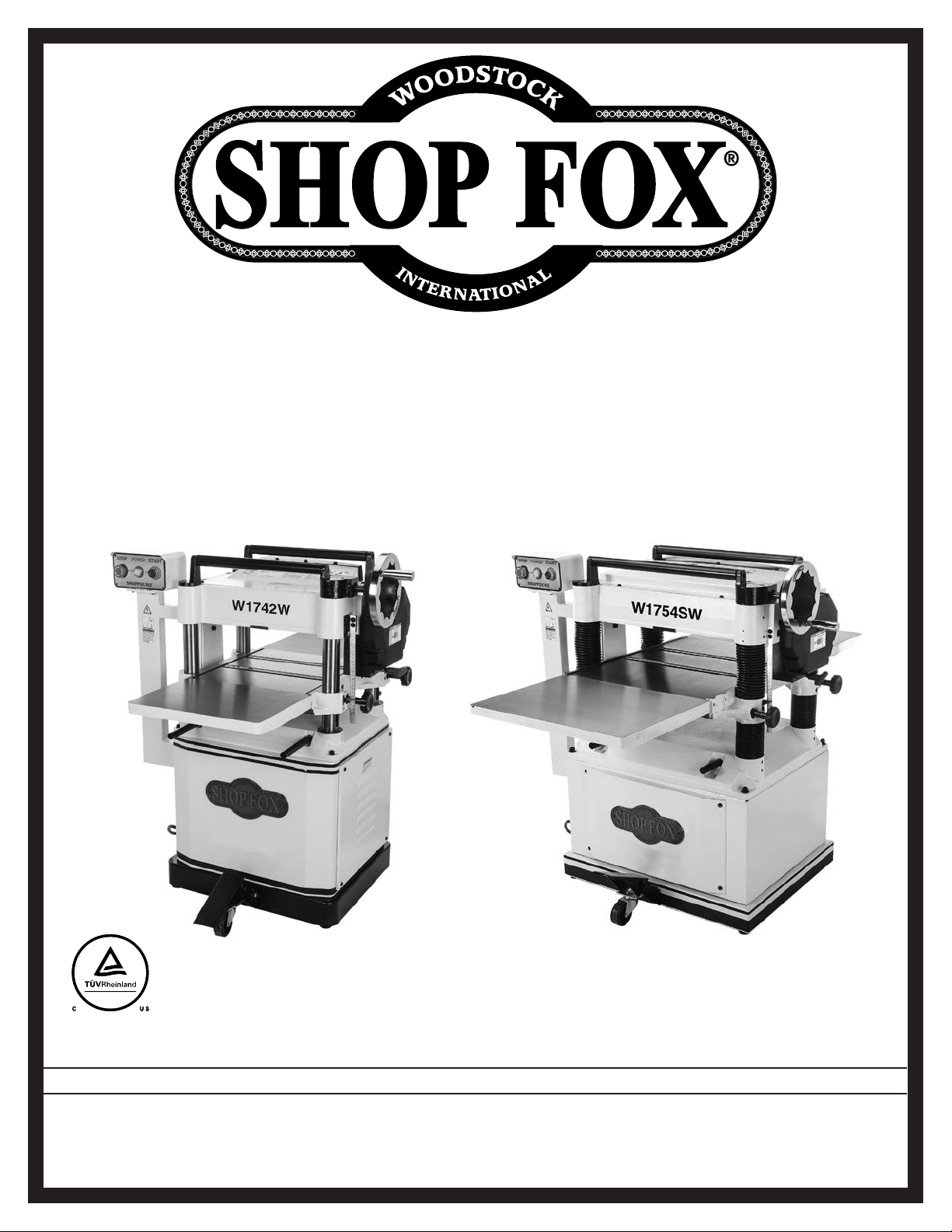
MODEL W1742W, W1742SW,
W1754W, W1754SW
15" & 20" PLANERS
OWNER'S MANUAL
(FOR MODELS MANUFACTURED SINCE 8/16)
Phone: (360) 734-3482 • Online Technical Support: techsupport@woodstockint.com
COPYRIGHT © JANUARY, 2016 BY WOODSTOCK INTERNATIONAL, INC. REVISED 08/16
WARNING: NO PORTION OF THIS MANUAL MAY BE REPRODUCED IN ANY SHAPE OR FORM WITHOUT
V2.08.16
THE WRITTEN APPROVAL OF WOODSTOCK INTERNATIONAL, INC.
#17486WK Printed in China
Page 2

This manual provides critical safety instructions on the proper setup,
operation, maintenance, and service of this machine/tool. Save this
document, refer to it often, and use it to instruct other operators.
Failure to read, understand and follow the instructions in this manual
may result in fire or serious personal injury—including amputation,
electrocution, or death.
The owner of this machine/tool is solely responsible for its safe use.
This responsibility includes but is not limited to proper installation in
a safe environment, personnel training and usage authorization,
proper inspection and maintenance, manual availability and comprehension, application of safety devices, cutting/sanding/grinding tool
integrity, and the usage of personal protective equipment.
The manufacturer will not be held liable for injury or property
damage from negligence, improper training, machine modifications or
misuse.
Some dust created by power sanding, sawing, grinding, drilling, and
other construction activities contains chemicals known to the State of
California to cause cancer, birth defects or other reproductive harm.
Some examples of these chemicals are:
• Lead from lead-based paints.
• Crystalline silica from bricks, cement and other masonry products.
• Arsenic and chromium from chemically-treated lumber.
Your risk from these exposures varies, depending on how often you
do this type of work. To reduce your exposure to these chemicals:
Work in a well ventilated area, and work with approved safety equipment, such as those dust masks that are specially designed to filter
out microscopic particles.
Page 3

Contents
INTRODUCTION .....................................2
Contact Info ....................................... 2
Machine Differences ............................. 2
Manual Accuracy .................................. 2
Machine Specifications .......................... 3
Identification ..................................... 5
Controls & Components ......................... 6
Internal Components ............................ 7
SAFETY ...............................................8
Standard Machinery Safety Instructions ...... 8
Additional Safety for Planers ................. 10
ELECTRICAL ....................................... 11
Circuit Requirements .......................... 11
Grounding Requirements ...................... 12
Extension Cords ................................ 12
SETUP .............................................. 13
Unpacking ....................................... 13
Items Needed for Setup ....................... 13
Inventory ........................................ 14
Cleaning Machine ............................... 15
Machine Placement ............................ 16
Lifting & Moving ................................ 17
Assembly ......................................... 18
Dust Collection ................................. 19
Checking Gearbox Oil Level .................. 20
Test Run .......................................... 21
OPERATIONS....................................... 22
General .......................................... 22
Workpiece Inspection .......................... 23
Wood Types ...................................... 23
Planing Tips ..................................... 24
Cutting Problems ............................... 24
Depth of Cut .................................... 26
Bed Roller Height .............................. 27
Setting Feed Rate .............................. 28
Adjusting/Replacing Knives
(W1742W & W1754W) ......................... 28
Adjusting/Replacing Knives ................... 28
Rotating/Replacing Cutterhead Inserts
(W1742SW & W1754SW) ....................... 30
ACCESSORIES ...................................... 31
Planer Accessories ............................. 31
MAINTENANCE .................................... 32
Schedule ......................................... 32
Cleaning & Protecting ......................... 32
Lubrication ...................................... 32
SERVICE ............................................ 35
General .......................................... 35
Tensioning/Replacing V-Belts ................. 35
Tensioning Table Height Chain ............... 36
Feed Rollers, Chip Breaker &
Pressure Bar Heights ........................... 37
Adjusting Roller Spring Tension .............. 41
Positioning Chip Deflector .................... 42
Calibrating Table Height Scale ............... 43
Anti-Kickback Fingers .......................... 43
Pulley Alignment ............................... 44
Troubleshooting ................................. 45
Electrical Safety Instructions ................. 47
W1742W & W1742SW Wiring Diagram ....... 48
W1754W & W1754SW Wiring Diagram ....... 49
PARTS: W1742W & W1742SW ................. 50
Headstock ....................................... 50
Table ............................................. 52
Base .............................................. 53
Gearbox .......................................... 54
Feed Gearing .................................... 55
Cabinet Stand ................................... 56
PARTS: W1754W & W1754SW ................. 58
Headstock ....................................... 58
Table ............................................. 60
Base .............................................. 61
Gearbox .......................................... 62
Feed Gearing .................................... 63
Cabinet Stand ................................... 64
PARTS: LABELS & COSMETICS.................. 66
WARRANTY ........................................ 69
SAFETYINTRODUCTION
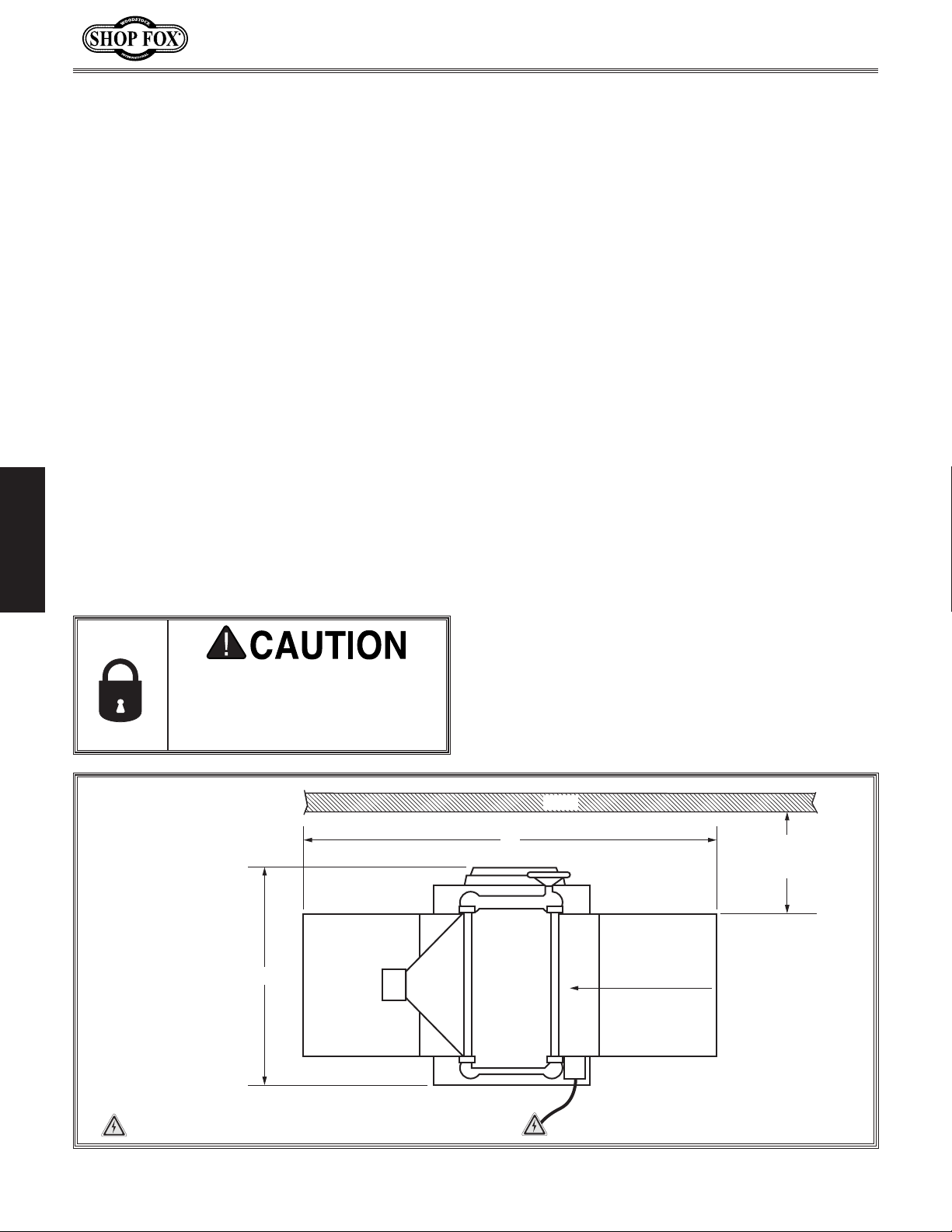
SET UPELECTRICAL MAINTENANCE
OPERATIONS
SERVICE PARTS
USE THE QUICK GUIDE PAGE LABELS TO SEARCH OUT INFORMATION FAST!
Page 4
INTRODUCTION
We are proud to provide a high-quality owner’s
manual with your new machine!
We
the
instructions, specifications, drawings, and photographs contained inside. Sometimes we make
mistakes, but our policy of continuous improvement
machine
you receive will be slightly different than what
is shown in the manual
If you find this to be the case, and the difference
between the manual and machine leaves you
confused about a procedure
check our website
for an updated version. W
manuals
and
on our website at
www.
Alternatively, you can call our Technical Support
for help. Before calling, make sure you write
down the
from the machine ID label (see below). Also, if
available, have a copy of your original purchase
receipt on hand. This information is required for
all Tech Support calls.
MODEL XXXX
MACHINE NAME
Motor:
Specification:
Specification:
Specification:
Specification:
Weight:
Specifications
To reduce risk of serious personal injury when using this
machine:
1. Read & understand owner’s manual before operating.
2. Always wear approved eye protection and respirator.
3. Only plug power cord into a grounded outlet.
4. Only use this machine to collect wood dust/chips—never
use to collect glass, metal, liquids, asbestos, silica,
animal parts, biohazards, burning material/ashes, etc.
5. Always disconnect power before servicing or cleaning.
6. Do not expose to rain or wet areas.
7. Keep hands, long hair, and loose clothing away from
inlet.
8. Never leave machine unattended while it is running.
9. Do not use if cord/plug becomes damaged—promptly
repair and protect cord from future damage.
10. Do not use without dust bag or filters in place.
11. Always wear a respirator when emptying bags.
12. Prevent unauthorized use by children or untrained users.
Date
Serial Number
Manufactured for Woodstock in Taiwan
WARNING!
We are committed to customer satisfaction. If
you have any questions or need help, use the
information below to contact us.
IMPORTANT: Before contacting, please get the
original purchase receipt, serial number, and
manufacture date of your machine. This information is required for all Technical Support
calls and it will help us help you faster.
We want your feedback on this manual. What did
you like about it? Where could it be improved?
Please take a few minutes to give us feedback.
Email: manuals@woodstockint.com
W1742W, W1742SW, W1754W, W1754SW (Mfd. Since 05/16)
INTRODUCTION
Contact Info
Woodstock International Technical Support
Phone: (360) 734-3482
Email: techsupport@woodstockint.com
Technical Documentation Manager
P.O. Box 2309
Bellingham, WA 98227
Manual Accuracy
made every effort to be exact with
also means that sometimes the
.
,
e post current
manual updates for free
woodstockint.com.
Manufacture Date and Serial Number
Machine Differences
• Models W1742W and W1742SW are 3 HP, 15"
planers.
— Model W1742W has a 3-knife cutterhead.
— Model W1742SW has a spiral cutterhead.
• Models W1754W and W1754SW are 5 HP, 20"
planers.
— Model W1754W has a 4-knife cutterhead.
— Model W1754SW has a spiral cutterhead.
Manufacture
Date
Serial Number
-2-
Page 5
W1742W, W1742SW, W1754W, W1754SW (Mfd. Since 05/16)
MACHINE
SPECIFICATIONS
© Woodstock International, Inc. • Phone #: (800) 840-8420 • Web: www.shopfox.biz
Model Number W1742W W1742SW W1754W W1754SW
Product Dimensions
Weight
Width (side-to-side) x Depth
(front-to-back) x Height
Foot Print (Length x Width) 19" x 23
Shipping Dimensions
Type Wood Crate
Weight 614 lbs. 625 lbs. 878 lbs. 891 lbs.
Width (side-to-side) x Depth
(front-to-back) x Height
Electrical
Power Requirement 240V, Single-Phase, 60 Hz
Full-Load Current Rating 12A 20A
Minimum Circuit Size 20A 30A
Connection Type Cord & Plug
Power Cord Included Yes
Power Cord Length 7 ft. 7 ft.
Power Cord Gauge 12 AWG
Plug Included Yes
Included Plug Type 6-20 L6-30
Switch Type Magnetic Switch w/Overload Protection
Motor
Type TEFC Capacitor-Start Induction
Horsepower 3 HP 5 HP
Phase Single-Phase
Amps 12A 20A
Speed 3450 RPM
Power Transfer Belt Drive
Bearings Sealed & Permanently Lubricated
Manufacturer Specifications
Country of Origin China
Warranty 1 Year
Approx. Assembly & Setup
Time
Serial Number Location ID Label
ISO 9001 Factory Yes
Certified by NRTL Yes
532 lbs. 534 lbs 781 lbs. 790 lbs.
1
38" x 42" x 44" 38" x 42" x 44" 44" x 56
1
⁄2" 23" x 29"
37" x 25" x 48" 37" x 25" x 48" 43" x 30" x 48" 43" x 30" x 48"
1 Hour
-3-
⁄2" x 45" 44" x 56 1⁄2" x 45"
INTRODUCTION
Page 6
W1742W, W1742SW, W1754W, W1754SW (Mfd. Since 05/16)
Model Number W1742W W1742SW W1754W W1754SW
Main Specifications
INTRODUCTION
Planer Size 15 in. 20 in.
Max. Cut Width 15 in. 20 in.
Max. Stock Thickness 8 in.
Min. Stock Thickness
Min. Stock Length 6
1
⁄2 in. 71⁄2 in.
Number of Cuts Per Inch 104, 56 104, 83
Number of Cuts Per Minute 15,000 20,000
Cutterhead Speed 5000 RPM
Planing Feed Rate 16, 20 FPM
Max. Cut Depth Planing Full
Width
Max. Cut Depth Planing
6-Inch Wide Board
Cutterhead Info
5
⁄32 in.
Cutterhead Type 3-Knife Spiral 4-Knife Spiral
Cutterhead Diameter 3 in. 3
Number of Knives 3 N/A 4 N/A
Knife Type
HSS, SingleSided, Solid
N/A
Knife Length 15 in. N/A 20 in. N/A
Knife Width 1 in. N/A 1 in. N/A
Knife Thickness
1
⁄8 in. N/A
Knife Adjustment Jack Screws N/A Jack Screws N/A
Number of Spirals N/A 4 N/A 4
Number of Indexable Cutters N/A 72 N/A 96
Cutter Insert Type N/A
Indexable
Carbide
Cutter Insert Length N/A 14 mm N/A 14 mm
Cutter Insert Width N/A 14 mm N/A 14 mm
Cutter Insert Thickness N/A 2 mm N/A 2 mm
Table Info
Table Movement 8 in.
Table Bed Length x Width 41
3
⁄4 x 16 in. 561⁄2 x 21 in.
Table Bed Thickness 2
Floor-to-Tab le Height 25–32
Construction
3
⁄4 in. 253⁄8–333⁄4 in.
Table Precision-Ground Cast Iron
Body Cast Iron
Stand/Cutterhead Assembly Steel
Feed Rollers Infeed: Serrated Steel/Outfeed: Rubber
Paint Type/Finish Powder Coated
3
⁄16 in.
1
⁄8 in.
3
⁄8 in.
1
⁄4 in.
1
⁄16 in.
HSS, SingleSided, Solid
1
⁄8 in. N/A
N/A
N/A
Indexable
Carbide
-4-
Page 7
W1742W, W1742SW, W1754W, W1754SW (Mfd. Since 05/16)
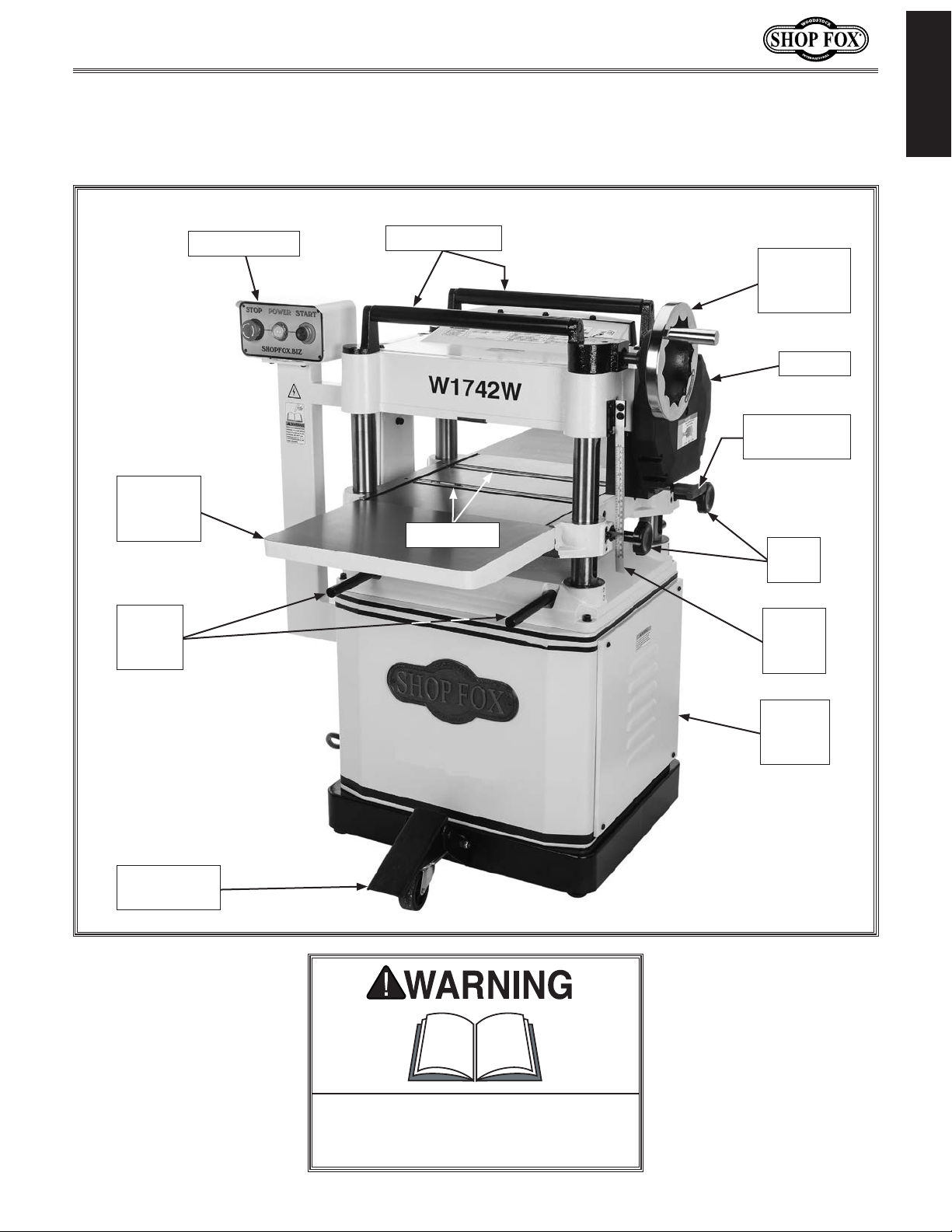
Become familiar with the names and locations of the controls and features shown below to better
Identification
INTRODUCTION
Front
Extension
Wing
Lifting
Bars
(2 of 4)
Control Panel
Return Rollers
Table
Height
Handwheel
Gearbox
Feed Rate
Control Knob
Bed Rollers
Table
Locks
Table
Height
Scale
Mobile-Base
Foot Pedal
Cabinet
Access
Panel
To reduce your risk of serious injury
or damage to the machine, read this
entire manual BEFORE using machine.
-5-
Page 8
W1742W, W1742SW, W1754W, W1754SW (Mfd. Since 05/16)
Controls & Components
Refer to the Figures 1–3 and the following descriptions to
INTRODUCTION
become familiar with the basic controls and components
of this machine. Understanding these items and how they
work will help you understand the rest of the manual and
stay safe when operating this machine.
A. Control Panel for Magnetic Switch: Green START
button turns motor ON when pressed. Red Emergency
STOP button turns motor OFF when pressed; for
safety purposes, this button will remain depressed
and prevent restarting until reset. Reset by rotating
clockwise until it pops out.
B. Table Height Handwheel: Raises and lowers table
to accommodate different workpiece thicknesses.
One complete revolution moves the table
approximately
1
⁄16".
To reduce your risk of serious injury
or damage to the machine, read this
entire manual BEFORE using machine.
A
B
C
C. Feed Rate Control Knob: Selects 20 FPM feed rate
when pushed in, and 16 FPM feed rate when pulled
out.
D. Table Locks: Secure table height position when
tightened.
E. Depth-of-Cut Limiter: Limits depth of cut to a
maximum of
F. Return Rollers: Assist sliding workpiece back to
operator following planing operation.
G. Dust Port: Connects to a dust collection system to
extract shavings and dust during operation.
H. Mobile-Base Foot Pedal: When engaged, lifts
machine onto casters for repositioning. When
disengaged, allows machine to rest firmly on floor
during operations.
1
⁄8" at full width.
E
D
Figure 1. Table elevation and feed
controls.
F
Figure 2. Return rollers and dust port.
G
-6-
H
Figure 3. Mobile-base foot pedal.
Page 9
W1742W, W1742SW, W1754W, W1754SW (Mfd. Since 05/16)
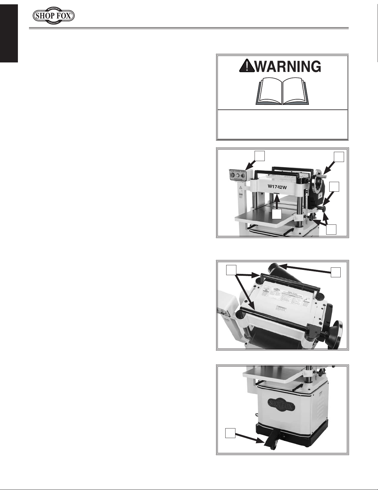
Internal Components
INTRODUCTION
FRONT
A
A. Anti-Kickback Fingers: Provide additional
safety for the operator.
B. Serrated Infeed Roller: Pulls the workpiece
toward the cutterhead.
C. Chip Breaker: Breaks off chips created by
the cutterhead to prevent tear out and
diverts the chips to the dust port.
D. Chip Deflector: Directs chips into the dust
hood.
E. Cutterhead: Holds the knives/indexable
carbide inserts that remove material from
the workpiece.
C
B
Workpiece
H H
Figure 4. Workpiece path and major planing components (side cutaway view).
D
E
I
F. Pressure Bar (W1754W & W1754SW):
Stabilizes the workpiece as it leaves the
cutterhead and assists in deflecting wood
particles toward the dust port.
G. Outfeed Roller: Pulls the workpiece
through the planer.
H. Table Rollers: Provide upward pressure on
the workpiece, enabling the feed rollers to
pull the workpiece along.
I. Planer Table: Provides a smooth and level
path for the workpiece as it moves through
the planer.
F
REAR
G
Like all machinery there is potential danger when operating this machine. Accidents are frequently caused by lack of familiarity or failure to pay attention. Use this machine with respect
and caution to decrease the risk of operator injury. If normal safety precautions are overlooked
or ignored, serious personal injury may occur.
-7-
Page 10

W1742W, W1742SW, W1754W, W1754SW (Mfd. Since 05/16)
SAFETY
OWNER’S MANUAL.
TRAINED OPERATORS ONLY.
DANGEROUS ENVIRONMENTS.
MENTAL ALERTNESS REQUIRED.
electrical components or improperly grounded
manual uses a series of symbols and signal words intended to convey the level of importance of the
safety messages. The progression of symbols is described below. Remember that safety messages by
SAFETY
For Your Own Safety,
Read Manual Before Operating Machine
The purpose of safety symbols is to attract your attention to possible hazardous conditions. This
SAFETY
themselves do not eliminate danger and are not a substitute for proper accident prevention measures—this responsibility is ultimately up to the operator!
NOTICE
Standard Machinery Safety Instructions
Standard Machinery Safety Instructions
Indicates an imminently hazardous situation which, if not avoided,
WILL result in death or serious injury.
Indicates a potentially hazardous situation which, if not avoided,
COULD result in death or serious injury.
Indicates a potentially hazardous situation which, if not avoided,
MAY result in minor or moderate injury.
This symbol is used to alert the user to useful information about
proper operation of the equipment or a situation that may cause
damage to the machinery.
Read and understand this
owner’s manual BEFORE using machine.
have a higher risk of being hurt or killed. Only
allow trained/supervised people to use this
machine. When machine is not being used,
disconnect power, remove switch keys, or
lock-out machine to prevent unauthorized
use—especially around children. Make
workshop kid proof!
machinery in areas that are wet, cluttered,
or have poor lighting. Operating machinery
in these areas greatly increases the risk of
accidents and injury.
alertness is required for safe operation of
machinery. Never operate under the influence
of drugs or alcohol, when tired, or when
distracted.
Untrained operators
Do not use
Full mental
ELECTRICAL EQUIPMENT INJURY RISKS. You can
be shocked, burned, or killed by touching live
machinery. To reduce this risk, only allow an
electrician or qualified service personnel to
do electrical installation or repair work, and
always disconnect power before accessing or
exposing electrical equipment.
DISCONNECT POWER FIRST. Always disconnect
machine from power supply BEFORE making
adjustments, changing tooling, or servicing
machine. This eliminates the risk of injury
from unintended startup or contact with live
electrical components.
EYE PROTECTION. Always wear ANSI-approved
safety glasses or a face shield when operating
or observing machinery to reduce the risk of
eye injury or blindness from flying particles.
Everyday eyeglasses are not approved safety
glasses.
-8-
Page 11

W1742W, W1742SW, W1754W, W1754SW (Mfd. Since 05/16)
WEARING PROPER APPAREL. Do not wear
HAZARDOUS
HEARING PROTECTION.
REMOVE ADJUSTING TOOLS.
INTENDED USAGE.
AWKWARD POSITIONS.
CHILDREN & BYSTANDERS.
GUARDS & COVERS.
FORCING MACHINERY. Do not force machine. It
will do the job safer and better at the rate for
loss of control. Before starting, verify machine
malfunction, leading to serious personal injury
from heated surfaces, high traffic areas, harsh
clothing, apparel, or jewelry that can become
entangled in moving parts. Always tie back
or cover long hair. Wear non-slip footwear to
avoid accidental slips, which could cause loss
of workpiece control.
DUST. Dust created while using
machinery may cause cancer, birth defects,
or long-term respiratory damage. Be aware of
dust hazards associated with each workpiece
material, and always wear a NIOSH-approved
respirator to reduce your risk.
Always wear hearing
protection when operating or observing
loud machinery. Extended exposure to this
noise without hearing protection can cause
permanent hearing loss.
machinery can become dangerous projectiles
upon startup. Never leave chuck keys,
wrenches, or any other tools on machine.
Always verify removal before starting!
intended purpose—never make modifications
without prior approval from Woodstock
International. Modifying machine or using
it differently than intended will void the
warranty and may result in malfunction or
mechanical failure that leads to serious
personal injury or death!
balance at all times when operating machine.
Do not overreach! Avoid awkward hand
positions that make workpiece control difficult
or increase the risk of accidental injury.
bystanders at a safe distance from the work
area. Stop using machine if they become a
distraction.
Only use machine for its
Tools left on
Keep proper footing and
Keep children and
which it was designed.
NEVER STAND ON MACHINE. Serious injury may
occur if machine is tipped or if the cutting
tool is unintentionally contacted.
STABLE MACHINE. Unexpected movement during
operation greatly increases risk of injury or
is stable and mobile base (if used) is locked.
USE RECOMMENDED ACCESSORIES. Consult
this owner’s manual or the manufacturer for
recommended accessories. Using improper
accessories will increase risk of serious injury.
UNATTENDED OPERATION. To reduce the risk
of accidental injury, turn machine OFF and
ensure all moving parts completely stop
before walking away. Never leave machine
running while unattended.
MAINTAIN WITH CARE. Follow all maintenance
instructions and lubrication schedules to
keep machine in good working condition. A
machine that is improperly maintained could
or death.
CHECK DAMAGED PARTS. Regularly inspect
machine for any condition that may affect
safe operation. Immediately repair or replace
damaged or mis-adjusted parts before
operating machine.
MAINTAIN POWER CORDS. When disconnecting
cord-connected machines from power, grab
and pull the plug—NOT the cord. Pulling the
cord may damage the wires inside, resulting
in a short. Do not handle cord/plug with wet
hands. Avoid cord damage by keeping it away
chemicals, and wet/damp locations.
SAFETY
accidental contact with moving parts or flying
debris—make sure they are properly installed,
undamaged, and working correctly.
Guards and covers reduce
EXPERIENCING DIFFICULTIES. If at any time
you experience difficulties performing the
intended operation, stop using the machine!
-9-
Contact Technical Support at (360) 734-3482.
Page 12

W1742W, W1742SW, W1754W, W1754SW (Mfd. Since 05/16)
MAIN PLANER INJURY RISKS. Familiarize yourself
KICKBACK.
AVOID MOVING PARTS
DULL/DAMAGED KNIVES/INSERTS.
INSPECTING STOCK.
BODY PLACEMENT. Stand to one side of planer
To reduce the risk
of kickback, never start planer with workpiece
adjusted before operation.
Additional Safety for Planers
with the main injury risks associated with
planers—always use common sense and good
SAFETY
judgement to reduce your risk of injury.
Main injury risks from planers: amputation/
lacerations from contact with the moving
cutterhead, entanglement/crushing injuries
from getting caught in moving parts, blindness
or eye injury from flying wood chips, or
impact injuries from workpiece kickback.
Know how to reduce the risk of
kickback and kickback-related injuries.
“Kickback” occurs during the operation when
the workpiece is ejected from the machine at
a high rate of speed. Kickback is commonly
caused by poor workpiece selection, unsafe
feeding techniques, or improper machine
setup/maintenance. Kickback injuries typically
occur as follows: (1) operator/bystanders
are struck by the workpiece, resulting in
impact injuries (i.e., blindness, broken bones,
bruises, death); (2) operator’s hands are
pulled into blade, resulting in amputation or
severe lacerations.
. Never remove guards/
covers or reach inside the planer during
operation or while connected to power. You
could be seriously injured if you accidentally
touch the spinning cutterhead or get
entangled in moving parts. If a workpiece
becomes stuck or sawdust removal is
necessary, turn planer OFF and disconnect
power before clearing.
during the entire operation to avoid getting
hit if kickback occurs.
GRAIN DIRECTION. Planing across the grain is
hard on the planer and may cause kickback.
Plane in the same direction or at a slight
angle with the wood grain.
PLANING CORRECT MATERIAL. Only plane
natural wood stock. DO NOT plane MDF,
OSB, plywood, laminates or other synthetic
materials that can break up inside the planer
and be ejected towards the operator.
LOOKING INSIDE PLANER. Wood chips fly around
inside planer at a high rate of speed during
operation. To reduce risk of injury from flying
material, DO NOT look inside planer during
operation.
CUTTING LIMITATIONS. To reduce risk of
kickback hazards or damage to machine,
do not exceed maximum depth of cut or
minimum board length and thickness found in
Data Sheet. Only feed one board at a time.
INFEED ROLLER CLEARANCE. The infeed
roller is designed to pull material into the
spinning cutterhead. To reduce the risk of
entanglement, keep hands, clothing, jewelry,
and long hair away from the infeed roller
during operation.
FEED WORKPIECE PROPERLY.
sharp, undamaged knives/inserts. Dull or
damaged knives/inserts increase the risk of
kickback.
To reduce the risk of
kickback injuries or machine damage,
thoroughly inspect and prepare the workpiece
before cutting. Verify workpiece is free of
nails, staples, loose knots or foreign material.
Workpieces with minor warping should be
jointed first or planed with the cupped side
facing the infeed table.
Only use
touching cutterhead. Allow cutterhead to
reach full speed before feeding, and do not
-10-
change feed speed during cutting operation.
WORKPIECE SUPPORT. To reduce risk of
kickback, always make sure workpiece can
move completely across table without rocking
or tipping. Use auxiliary support stands for
long stock.
SECURE KNIVES/INSERTS. Loose knives or
improperly set inserts can become dangerous
projectiles or cause machine damage. Always
verify knives/inserts are secure and properly
Page 13
W1742W, W1742SW, W1754W, W1754SW (Mfd. Since 05/16)
This machine must be connected to the correct size and
type of power supply circuit, or fire or electrical damage
may occur. Read through this section to determine if an
adequate power supply circuit is available. If a correct
circuit is not available, a qualified electrician MUST install
one before you can connect the machine to power.
A power supply circuit includes all electrical equipment
between the breaker box or fuse panel in the building
and the machine. The power supply circuit used for
this machine must be sized to safely handle the fullload current drawn from the machine for an extended
period of time. (If this machine is connected to a circuit
protected by fuses, use a time delay fuse marked D.)
The full-load current rating is the amperage a machine
draws at 100% of the rated output power. On machines
with multiple motors, this is the amperage drawn by the
largest motor or sum of all motors and electrical devices
that might operate at one time during normal operations.
or machine damage. To reduce this risk,
a dedicated circuit—
where only one machine will be running
multiple machines will be running at the
This machine is prewired to operate on a power supply
circuit that has a verified ground and meets the following
requirements:
ELECTRICAL
Circuit Requirements
The machine must be properly set up
before it is safe to operate. DO NOT
connect this machine to the power
source until instructed to do so later in
this manual.
ELECTRICAL
Full-Load Current Rating
W1742W & W1742SW
Full-Load Current Rating ............................. 12 Amp s
W1754 W & W1754S W
Full-Load Current Rating ............................. 20 Amps
W1742W & W1742SW Circuit Requirements
Circuit Type ......................240V, 60 Hz, Single-Phase
Circuit Size ............................................. 20 Amps
Plug/Receptacle .................................... NEMA 6-20
W1754W & W1754SW Circuit Requirements
Circuit Type ......................240V, 60 Hz, Single-Phase
Circuit Size ............................................. 30 Amps
Plug/Receptacle ...................................NEMA L6-30
Incorrectly wiring or grounding this
machine can cause electrocution, fire,
only an electrician or qualified service
personnel should do any required
electrical work on this machine.
NOTICE
The circuit requirements listed in this
manual apply to
at a time. If this machine will be
connected to a shared circuit where
same time, consult with an electrician
to ensure that the circuit is properly
sized for safe operation.
-11-
Page 14
W1742W, W1742SW, W1754W, W1754SW (Mfd. Since 05/16)
This machine MUST be grounded. In the event of certain
types of
a path of least resistance for electric current
order
Improper connection of the equipment-grounding
will
increase
insulation
grounding
cord or plug is necessary, do not connect the equipmentgrounding
Check with a qualified electrician or service personnel
if
or if
properly grounded.
plug is damaged or worn, disconnect it from power, and
immediately replace it with a new one.
This machine is equipped with a power cord that has an
equipment-grounding
insert plug into a matching
properly installed and grounded in accordance with all
local codes and ordinances. DO NOT modify provided plug!
We do not recommend using an extension cord with
Any extension cord used with this machine must contain a
plug and receptacle, and
meet the following requirements:
the available receptacle or the machine
Grounding Requirements
malfunctions or breakdowns, grounding provides
to travel—in
to reduce the risk of electric shock.
wire
the risk of electric shock. The wire with green
(with/without yellow stripes) is the equipment-
wire. If repair or replacement of the power
The machine must be properly set up
before it is safe to operate. DO NOT
connect this machine to the power
source until instructed to do so later in
this manual.
wire to a live (current carrying) terminal.
you do not understand these grounding requirements,
ELECTRICAL
you are in doubt about whether the tool is
If you ever notice that a cord or
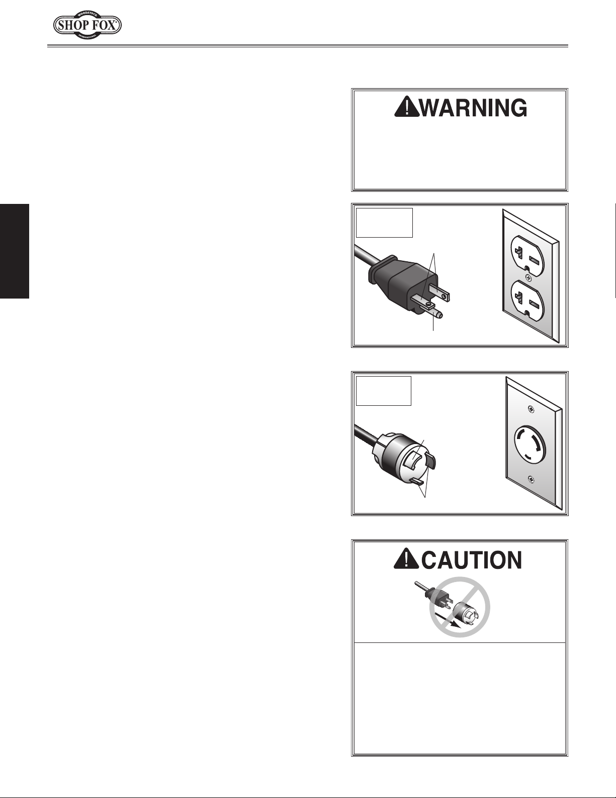
For 240V Connection
wire and a grounding plug. Only
receptacle (outlet) that is
Extension Cords
this machine. Extension cords cause voltage drop, which
may damage electrical components and shorten motor
life. Voltage drop increases with longer extension cords
and smaller gauge sizes (higher gauge numbers indicate
smaller sizes).
W1742W/
W1742SW
Current Carrying Prongs
6-20 PLUG
Grounding Prong
Figure 5. NEMA 6-20 plug & receptacle.
W1754W/
W1754SW
Grounding Prong
Current Carrying Prongs
Figure 6. NEMA L6-30 plug & receptacle.
GROUNDED
6-20 RECEPTACLE
L6-30 GROUNDED
LOCKING
RECEPTACLE
is Hooked
L6-30
LOCKING
PLUG
ground wire, match the required
Minimum Gauge Size at 240V ...................... 12 AWG
Maximum Length (Shorter is Better) ................50 ft.
No adapter should be used with the
required plug. If the plug does not fit
must be reconnected to a different
type of circuit, the reconnection must
be made by an electrician or qualified
service personnel and it must comply
with all local codes and ordinances.
-12-
Page 15
W1742W, W1742SW, W1754W, W1754SW (Mfd. Since 05/16)
This machine presents
serious injury hazards
to untrained users. Read
to become familiar with
tions before starting the
This machine has been carefully packaged for safe
transportation. If you notice the machine has been
damaged during shipping, please contact your authorized
Shop Fox dealer immediately.
The following items are needed, but not included, to set
up your machine.
SETUP
Unpacking
Items Needed for Setup
Description Qty
• Additional People ..........................................1
• Safety Glasses ................................ 1 Per Person
• Forklift (rated for at least 1000 lbs.) ..................1
• Cleaner/Degreaser ............................ As Needed
• Disposable Shop Rags ......................... As Needed
• Phillips Screwdriver #2 ...................................1
• Open-End Wrench or Socket 12mm .....................1
• Open-End Wrench or Socket 14mm .....................1
• Hex Wrenches 3, 4, 5, 6, 8mm .....................1 Ea.
• Straightedge 4' .............................................1
• Dust Collection System ...................................1
• 4" Dust Hose w/Clamps (W1742W & W1742SW) ......1
• 5" Dust Hose w/Clamps (W1754W & W1754SW) ......1
through this entire manual
the controls and opera-
machine!
Wear safety glasses during
entire setup process!
SETUP
USE helpers or power
lifting equipment to lift
this machine. Otherwise,
serious personal injury
may occur.
-13-
Page 16
Inventory
The following is a list of items shipped with your machine.
Before beginning setup, lay these items out and inventory
them.
Note:
check around/inside the machine and packaging materials.
Often, these items get lost in packaging materials while
unpacking or they are pre-installed at the factory.
W1742W, W1742SW, W1754W, W1754SW (Mfd. Since 05/16)
If you cannot find an item on this list, carefully
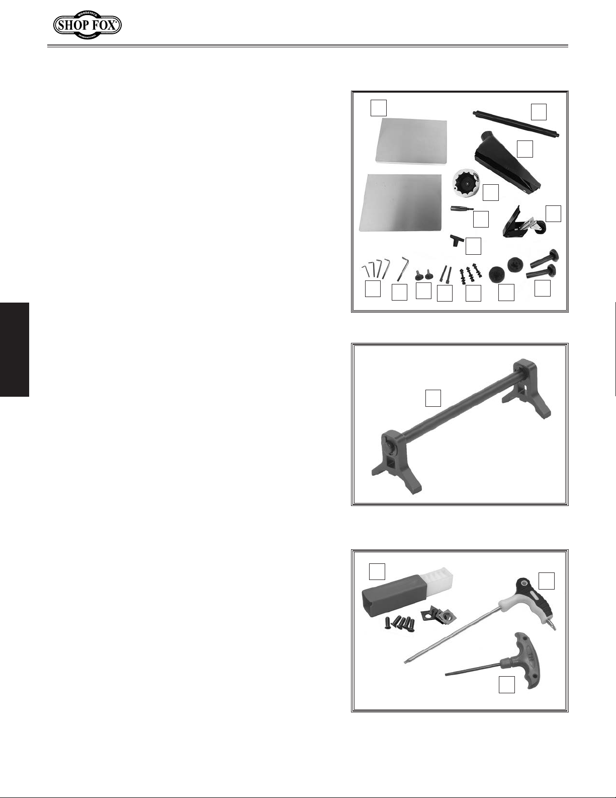
Box Contents (Figure 7) Qty
A. Planer (Not Shown) ........................................1
B. Extension Wings ............................................2
C. Return Roller (15" Models Only) .........................1
D. Dust Hood ...................................................1
E. Handwheel ..................................................1
F. Handwheel Handle ........................................1
G. Foot Pedal Caster Assembly ..............................1
H. Feed Rate "T" Knob M8-1.25 .............................1
I. Hex Wrenches 3, 4, 5, 6mm ........................1 Ea.
J. Hex Wrench 8mm (20" Models Only)....................1
K. Rubber Foot Assemblies ..................................2
SETUP
L. Cap Screws M8-1.25 x 60 (Rear Wheels) ...............2
Lock Washers 8mm (Rear Wheels) ......................2
M. Cap Screws M8-1.25 x 50 (Foot Pedal) .................3
Flat Washers 8mm (Foot Pedal) .........................6
Lock Washers 8mm (Foot Pedal) ........................3
Hex Nuts M8-1.25 (Foot Pedal) ..........................3
N. Rear Wheels ................................................2
O. Table Lock Star Knobs (15" Models Only) ..............2
Included with Straight-Knife Planers (Figure 8)
P. Knife-Setting Jig ...........................................1
Included with Spiral Cutterhead Planers (Figure 9)
Q. Spare Cutterhead Inserts .................................5
Flat Head Torx Screws T-20 M6-1 x 15 .................5
R. L-Handle Torx Wrench T20 ...............................1
S. T-Handle Torx Wrench T20 ...............................1
B
E
F
H
I
Figure 8. Knife-setting jig for straight-
Q
K
J
Figure 7. Loose inventory.
L M
P
knife planers.
N
C
D
G
O
R
S
Figure 9. Spare cutterhead inserts and
Torx wrenches for spiral cutterhead
planers.
-14-
Page 17
W1742W, W1742SW, W1754W, W1754SW (Mfd. Since 05/16)
To prevent
machine, the factory has coated t
of your machine
compound
I
be difficult to
coating is as easy as possible, please gather the correct
cleaner, lubricant, and tools listed below:
• Cleaner/degreaser
and grease
• Safety glasses & disposable gloves
•
• Disposable Rags
To
1.
2.
3
4
5
6
immediately coat with a quality metal protectant.
Cleaning Machine
corrosion during shipment and storage of your
with a heavy-duty rust prevention
.
f you are unprepared or impatient, this compound can
remove. To ensure that the removal of this
designed to remove storage wax
Solvent brush or paint brush
remove rust preventative coating, do these steps:
DISCONNECT MACHINE FROM POWER!
he bare metal surfaces
Gasoline and petroleum
products have low flash
points and can explode
or cause fire if used to
clean machinery. Avoid
using these products
to clean machinery.
Many cleaning solvents
are toxic if inhaled.
Minimize your risk
by only using these
products in a well
ventilated area.
SETUP
Put on safety glasses and disposable gloves.
. Coat the rust preventative with a liberal amount of
cleaner/degreaser, then let it soak for 5–10 minutes.
. Wipe off surfaces. If your cleaner/degreaser is
effective, the coating will wipe off easily.
Tip: An easier way to clean off thick coats of rust
preventative from flat surfaces is to use a PLASTIC
paint scraper to scrape off the majority of the
coating before wiping it off with your rag. (Do
not use a metal scraper or you may scratch your
machine.)
. Repeat cleaning steps as necessary until all of the
compound is removed.
. To prevent rust on freshly cleaned surfaces,
In a pinch, automotive degreasers,
mineral spirits or WD•40 can be used
to remove rust preventative coating.
Before using these products, though,
test them on an inconspicuous area of
your paint to make sure they will not
damage it.
-15-
Page 18
Machine Placement
Weight Load
Refer to the
weight of your machine. Make sure that the
surface upon which the machine is placed will
bear the weight of the machine, additional
equipment that may be installed on the
machine, and the heaviest workpiece that will
be used. Additionally, consider the weight of
the operator and any dynamic loading that may
occur when operating the machine.
Space Allocation
Consider the largest size of workpiece that
will be processed through this machine and
provide enough space around the machine
for adequate operator material handling or
the installation of auxiliary equipment. With
permanent installations, leave enough space
around the machine to open or remove doors/
covers as required by the maintenance and
service described in this manual.
required space allocation.
Physical Environment
The physical environment where your machine is
operated is important for safe operation and the
ambient temperature range exceeds 41°–104°F;
(non-condensing); or the environment is subject
source. Make sure all power cords are protected
chemicals, or other hazards. Make sure to leave
Machine Specifications for the
W1742W, W1742SW, W1754W, W1754SW (Mfd. Since 05/16)
longevity of its components. For best results,
operate this machine in a dry environment
that is free from excessive moisture, hazardous
chemicals, airborne abrasives, or extreme
conditions. Extreme conditions for this type
of machinery are generally those where the
the relative humidity range exceeds 20–95%
to vibration, shocks, or bumps.
Electrical Installation
Place this machine near an existing power
SETUP
See below for
Model W1742W
X = 42"
Y = 38"
Model W1742SW
X = 42"
Y = 38"
Model W1754W
X = 56½"
Y = 44"
Model W1754SW
X = 56½"
Y = 44"
Children or untrained people
may be seriously injured by this
machine. Only install in an access
restricted location.
Location Where Power Source Enters Machine
Y
2.5' Space between any kind of serviceable area and the wall
(including any maintenance access panels, electrical boxes,
body panel covers for coolant tanks, stand panels for accessing
V-belts, etc.). This will allow customers enough work space for
Port
from traffic, material handling, moisture,
access to a means of disconnecting the power
source or engaging a lockout/tagout device.
EXAMPLE ONLY
WILL SHOW:
Minimum Clearances
Location of Dust Port
Swing of Doors to 90°
maintenance or service
Lighting
Lighting around the machine must be adequate
enough that operations can be performed
safely. Shadows, glare, or strobe effects that
may distract or impede the operator must be
eliminated.
Wall
X
Feed DirectionDust
Min. 30"
for Maintenance
= Electrical Connection Illustration Not To Scale
Figure 10. Working clearances.
-16-
Page 19
W1742W, W1742SW, W1754W, W1754SW (Mfd. Since 05/16)
from improperly lifting machine or
Lifting & Moving
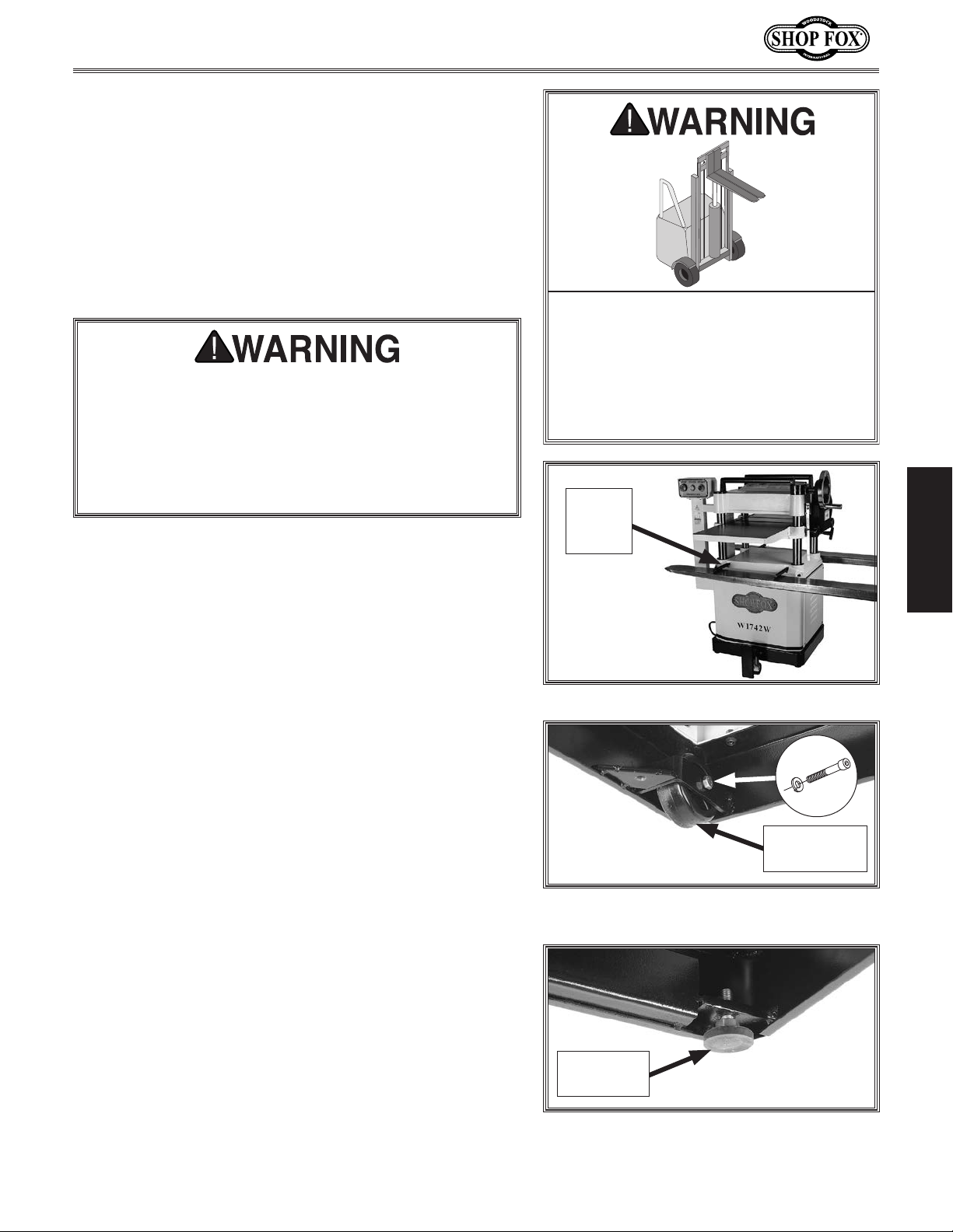
The planer is equipped with four lifting bars that
extend in order to lift and place the planer, as shown in
Figure 11.
The rear wheels and front feet mount to the bottom of
the machine. Therefore, the best time to assemble these
components is while the machine is elevated safely by the
forklift.
HEAVY LIFT!
Straining or crushing injury may occur
When installing rear wheels and front feet in Steps
2–3, machine MUST be fully supported by forklift
to prevent machine from falling, causing serious
crushing injury or death. If machine can not be
sufficiently supported during the next two steps, we
recommend temporarily setting machine on supports
such as 4 x 4 blocks to raise it off the ground.
To lift and place machine, do these steps:
1. Use forklift to lift machine off pallet (see
Figure 11).
Tip: When positioning lift forks, place shop rags or
cardboard between forks and cabinet stand to avoid
scratching paint.
2. While machine is elevated, install rear wheels
using (2) M8-1.25 X 60 cap screws and (2) 8mm lock
washers (see Figure 12).
some of its parts. To reduce this risk,
get help from other people and use
a forklift (or other lifting equipment)
rated for weight of this machine.
Lifting
Bar
(1 of 4)
Figure 11. Lifting planer with forklift.
x 2
SETUP
3. Install both front feet (see Figure 13).
4. Set machine down in suitable location.
Rear Wheel
(1 of 2)
Figure 12. Rear wheels installed with
machine elevated by forklift.
Front Foot
(1 of 2)
Figure 13. Front feet installed with
machine elevated by forklift.
-17-
Page 20
W1742W, W1742SW, W1754W, W1754SW (Mfd. Since 05/16)
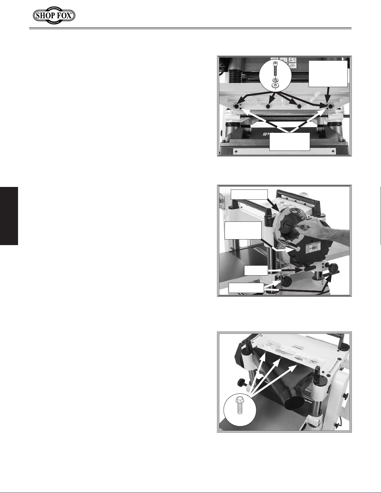
Assembly
To assemble planer, do these steps:
1. W1742W & W1742SW: Attach each table extension
wing to planer table with (2) pre-installed M8-1.25
x 25 cap screws, 8mm lock washers, and 8mm flat
washers,. Do not fully tighten cap screws at this
time.
W1754W & W1754SW: Attach each table extension
wing to planer table with (4) pre-installed M10-1.5 x
25 cap screws, 10mm lock washers, and 10mm flat
washers (see Figure 14). Do not fully tighten cap
screws at this time.
2. Using a straightedge as a guide, and table
adjustment set screws and cap screws for leveling
control, position extension wings even with table
and fully tighten cap screws from Step 1.
Adjustment
Set Screws
(1 of 2)
Adjustment
Cap Screws
Figure 14. Front extension wing installed
(Model W1754SW shown).
Handwheel
Note: Be aware that bed rollers will give you a false
SETUP
reading with your straightedge if they are raised
above table. Move them down or work around them
when leveling extension wings (refer to Bed Roller
Height on Page 27 for more information).
3. W1742W & W1742SW Only: Remove two preinstalled hex nuts from each table locking rod, then
install table lock star knobs on locking rods (see
Figure 15).
Note: Pre-installed hex nuts on table locking rods
are for shipping purposes only and may be discarded
after removal.
4. Thread handwheel handle into handwheel (see
Figure 15).
5. Thread T-knob onto feed rate shaft (see Figure 15).
6. Secure handwheel on shaft with pre-installed M5-.8 x
16 cap screw and 5mm flat washer (see Figure 15).
Handwheel
Handle
T-Knob
Star Knobs
Figure 15. Installing table height
handwheel, T-knob and table lock star
knobs installed.
7. Attach top and bottom of dust hood to planer
with (6) pre-installed M6-1 x 12 flange bolts
(see Figure 16).
3 of 6
Figure 16. Dust hood attached
(Model W1742W shown).
-18-
Page 21
W1742W, W1742SW, W1754W, W1754SW (Mfd. Since 05/16)
Do not confuse this CFM recommendation with the rating
of the dust collector. To determine the CFM at the dust
port, you must consider these variables: (1) CFM rating of
the dust collector, (2) hose type and length between the
dust collector and the machine, (3) number of branches
or wyes, and (4) amount of other open lines throughout
the system. Explaining how to calculate these variables
is beyond the scope of this manual. Consult an expert or
purchase a good dust collection “how-to” book.
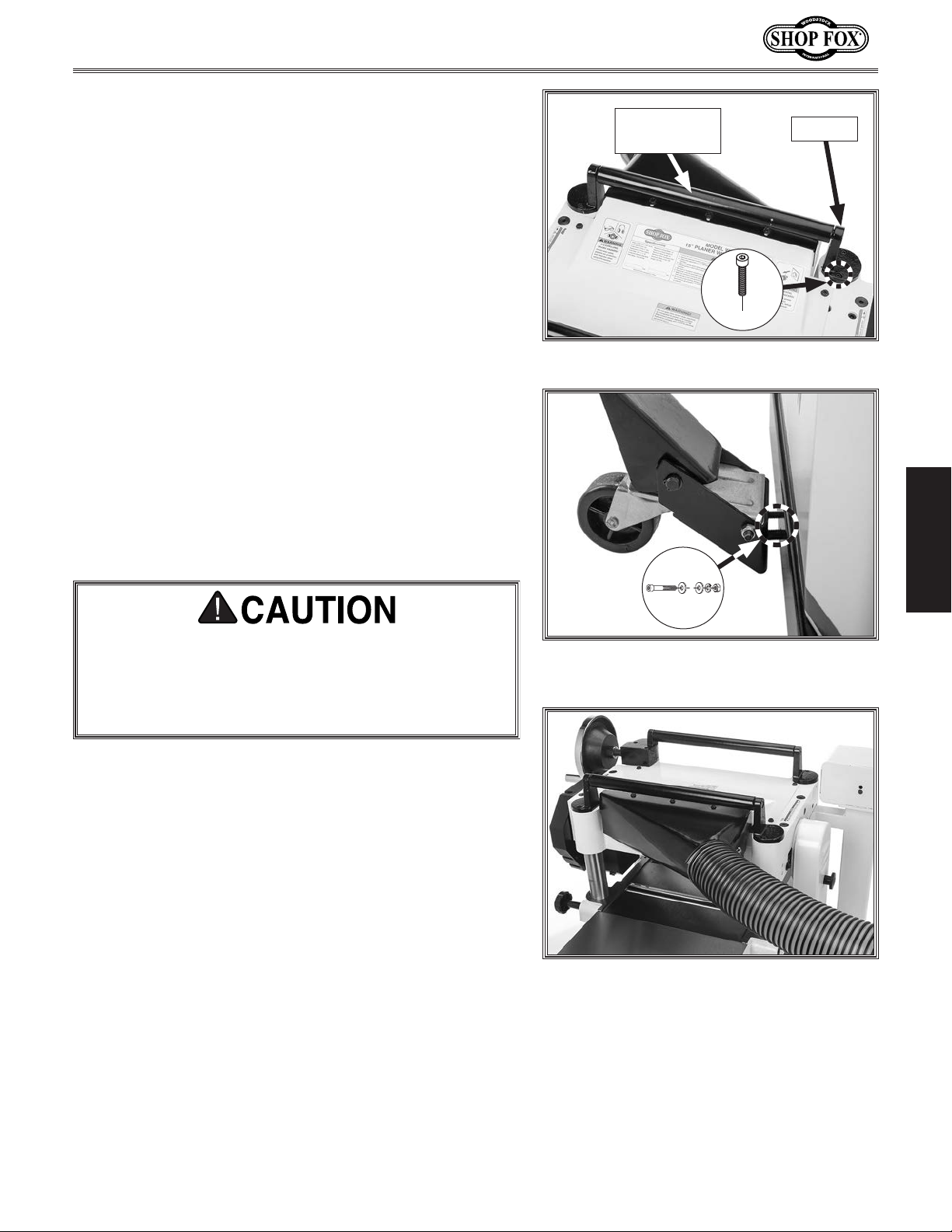
8. W1742W & W1742SW Only: Remove two preinstalled cap screws and rear return roller bracket
shown in Figure 17. Mount rear return roller
between brackets, then re-install cap screws.
Note: Models W1742W & W1742SW ship with the
rear return roller as separate inventory, because for
these models, the return roller blocks access to the
dust hood fasteners. Therefore, with these models,
the rear return roller must be installed AFTER the
dust hood.
9. Attach foot-pedal caster assembly to bottom of
machine using (3) M8-1.25 x 50 cap screws, (3) 8mm
lock washers, (6) 8mm flat washers, and (3) M8-1.25
hex nuts (see Figure 18).
Dust Collection
Rear Return
Roller
x 2
Figure 17. Return roller bar installed.
Bracket
Recommended CFM at Dust Port
• W1742W & W1742SW ............................400 CFM
• W1754W & W1754SW ............................625 CFM
This machine creates substantial amounts of dust
during operation. Breathing airborne dust on a regular basis can result in permanent respiratory illness.
Reduce your risk by wearing a respirator and capturing the dust with a dust collection system.
SETUP
x 3
Figure 18. Attaching foot-pedal caster
assembly to bottom of machine.
To connect the machine to a dust collection system, fit
a 4" dust hose (W1742W & W1742SW) or a 5" dust hose
(W1754W & W1754SW) over the dust port, and secure in
place with a hose clamp (see Figure 19). Tug the hose to
make sure it does not come off.
Note: A tight fit is necessary for proper performance.
Figure 19. Dust hose connected to dust
port.
-19-
Page 22

W1742W, W1742SW, W1754W, W1754SW (Mfd. Since 05/16)
Checking Gearbox Oil
Level
Before starting your machine for the first time, make sure
the gearbox has oil. The proper oil level is just even with
the bottom of the fill plug hole. The gearbox uses ISO 320
or SAE 140 gear oil. SAE 85W–140 multi-weight gear oil can
also be used as a substitute. DO NOT mix oil types.
Note: Although it is not necessary to remove the drive
chain cover to access the fill plug (see Figure 20), it is
more convenient to do so. To remove the cover, remove
the seven cap screws that secure it to the planer.
To check gearbox oil level, do these steps:
Fill Plug
1. Remove gearbox fill plug (see Figure 20).
2. Dip short end of a clean hex wrench inside fill hole,
and then remove it.
— If the end of the hex wrench is coated with oil,
SETUP
Note: We recommend that you replace the gearbox oil
after the first 20 hours of operation. This is a normal
break-in procedure and will help maximize the service life
of the machine by flushing away any particles from the
break-in and manufacturing process.
then the gearbox oil level is okay. Replace the fill
plug and continue with setup.
— If the end of the hex wrench is not coated with
oil, then you need to add more oil. Refer to
Gearbox Oil on Page 34 for instructions on how to
do this.
Figure 20. Drive chain cover removed to
access gearbox fill plug.
-20-
Page 23

W1742W, W1742SW, W1754W, W1754SW (Mfd. Since 05/16)
performed. Operating an improperly set
Once assembly is complete, test run the machine to
ensure it is properly connected to power and safety
components are functioning properly.
If you find an unusual problem during the test run,
immediately stop the machine, disconnect it from power,
and fix the problem BEFORE operating the machine again.
The
section of this
manual can help.
Test Run
Troubleshooting table in the SERVICE
The test run consists of verifying the following: 1) The
motor powers up and runs correctly, and 2) the safety
disabling mechanism on the switch works correctly.
To test run the machine, do these steps:
1. Clear all setup tools away from machine.
2. Connect machine to power supply.
Serious injury or death can result
from using this machine BEFORE
understanding its controls and related
safety information. DO NOT operate, or
allow others to operate, machine until
the information is understood.
DO NOT start machine until all
preceding setup instructions have been
up machine may result in malfunction
or unexpected results that can lead
to serious injury, death, or machine/
property damage.
SETUP
3. Push STOP button in, then twist it clockwise so it
pops out—this resets the switch so it will start the
machine (see Figure 21).
4. Push START button to turn machine ON. A correctly
operating machine runs smoothly with little or no
vibration or rubbing noises.
5. Press STOP button to turn machine OFF.
6. WITHOUT resetting switch, press START button. The
machine should not start.
— If machine does not start, the STOP button safety
feature is working correctly. Congratulations! The
Test Run is complete.
— If machine does start (with STOP button pushed
in), immediately disconnect power to machine.
The STOP button safety feature is not working
correctly. This safety feature must work properly
before proceeding with regular operations. Refer
to Troubleshooting on Page 45, or call Tech
Support for help.
I
S
W
T
T
To reset switch,
twist button
clockwise.
Figure 21. Resetting the switch.
After approximately 16 hours of
operation, V-belts will stretch and seat
into pulley grooves and need to be
properly tensioned to avoid severely
reducing life of V-belts. Refer to
Tensioning/Replacing V-Belts on Page
35 for detailed instructions.
-21-
Page 24

OPERATIONS
This machine will perform many types of operations
that are beyond the scope of this manual. Many of these
operations can be dangerous or deadly if performed
incorrectly.
The instructions in this section are written with the
understanding that the operator has the necessary
knowledge and skills to operate this machine. If at any
time you are experiencing difficulties performing any
operation, stop using the machine!
The overview below provides the novice machine operator
with a basic understanding of how the machine is used
during operation, so the machine controls/components
discussed later in this manual are easier to understand.
Due to its generic nature, this overview is
to be an instructional guide.
General
W1742W, W1742SW, W1754W, W1754SW (Mfd. Since 05/16)
To reduce your risk of serious injury
or damage to the machine, read this
entire manual BEFORE using machine.
NOT intended
To complete a typical operation, the operator does the
following:
1. Examines workpiece to make sure it is suitable for
planing.
2. Puts on safety glasses or face shield, a respirator,
and ear protection.
OPERATIONS
3. Places workpiece on table with flat side down
and correctly adjusts table height for workpiece
thickness and depth of cut.
— If workpiece is bowed, operator surface planes
workpiece on a jointer until one side is flat. Doing
so ensures that it sits solidly on planer table
4. When all safety precautions have been taken, turns
5. Stands to one side of planer path to reduce risk of
during operation.
planer ON.
kickback injuries, then feeds workpiece into planer
until infeed roller grabs it.
-22-
Eye injuries, respiratory problems, or
hearing loss can occur while operating
this tool. Wear personal protective
equipment to reduce your risk from
these hazards.
Note: Infeed and outfeed rollers
control feed rate of workpiece as it
passes through planer. Operator does
not push or pull on workpiece.
— If cut is too deep and bogs down
planer, operator immediately
reduces depth of cut.
6. Once workpiece is clear of outfeed
roller and stops moving, operator
removes workpiece from outfeed table
and measures workpiece thickness. If
further planing is required, operator
raises table slightly (approximately
1
⁄2 turn of the handwheel), then
to
feeds workpiece into front of planer
again.
7. Operator repeats this process until
desired thickness is achieved, then
turns machine OFF.
1
⁄4
Page 25

W1742W, W1742SW, W1754W, W1754SW (Mfd. Since 05/16)
Workpiece Inspection
Some workpieces are not safe to use or may
require modification before they are. Before
cutting, inspect all workpieces for the
following:
• Material Type: This machine is only
intended for workpieces of natural wood
fiber. Attempting to use workpieces of any
other material that may break apart during
operation could lead to serious personal
injury and property damage.
• Foreign Objects: Inspect lumber for
defects and foreign objects (nails, staples,
imbedded gravel, etc,). If you have any
question about the quality of your lumber,
DO NOT use it. Remember, wood stacked on
a concrete floor can have small pieces of
stone or concrete pressed into the surface.
• Large/Loose Knots: Loose knots can
become dislodged during operation. Large
knots can cause kickback and machine
damage. Always use workpieces that do not
have large/loose knots.
• Wet or "Green" Stock: Avoid using wood
with a high water content. Wood with more
than 20% moisture content or wood exposed
to excessive moisture (such as rain or
snow), will cut poorly and cause excessive
wear to the machine. Excess moisture
can also hasten rust and corrosion of the
machine and/or individual components.
• Excessive Warping: Workpieces with
excessive cupping, bowing, or twisting are
dangerous to cut because they are unstable
and often unpredictable when being
cut. DO NOT use workpieces with these
characteristics!
• Minor Cupping: Workpieces with slight
cupping can be safely supported if the
cupped side is facing the table. On the
contrary, a workpiece supported on the
bowed side will rock during operation and
could cause severe injury from kickback.
Wood Types
The species of wood, as well as its condition,
greatly affects the depth of cut the planer can
effectively take with each pass.
The chart in the figure below shows the Janka
Hardness Rating for a number of commonly
used species. The larger the number, the harder
the workpiece, and the less material should be
removed in any one pass for good results.
Note: The Janka Hardness Rating is expressed in
pounds of force required to embed a 0.444" steel
ball into the surface of the wood to a depth
equal to half the ball's diameter.
Species
Ebony 3220
Red Mahogany 2697
Rosewood 1780
Red Pine 1630
Sugar Maple 1450
White Oak 1360
White Ash 1320
American Beech 1300
Red Oak 1290
Black Walnut 1010
Teak 1000
Black Cherry 950
Cedar 900
Sycamore 770
Douglas Fir 660
Chestnut 540
Hemlock 500
White Pine 420
Basswood 410
Eastern White Pine 380
Balsa 100
Figure 22. Janka Hardness Rating for some
common wood species.
Janka
Hardness
OPERATIONS
-23-
Page 26

W1742W, W1742SW, W1754W, W1754SW (Mfd. Since 05/16)
Planing Tips
• Inspect your lumber for twisting or cupping,
and surface one face on a jointer if
necessary before planing workpiece.
• Scrape off all glue when planing glued-up
panels. Dried glue can quickly dull knives/
inserts.
• DO NOT plane more than one piece at a
time.
• Never remove more than the recommended
amount of material on each pass. Only
remove a small amount of material on each
pass when planing wide or dense stock.
• Support the workpiece on both ends. Get
assistance from another person if you are
planing long lumber, or use roller stands to
support the workpiece.
• Measure the workpiece thickness with
calipers to get exact results.
• Carefully inspect all stock to make sure
it is free of large knots or foreign objects
that may damage your knives/inserts, cause
kickback, or be ejected from the planer.
• When possible, plane equal amounts on
OPERATIONS
each side of the board to reduce the
chance of twisting or cupping.
• Use the entire width of the planer to
wear knives/inserts evenly. With narrow
workpieces, alternate between far left,
far right, and the middle of the table.
Your knives/inserts will remain sharp much
longer.
• To avoid "chip marks," always plane WITH
the grain direction of the wood. Never
plain cross-grain or end-grain.
Cutting Problems
Below is a list of wood characteristics you
may encounter when planing. The following
descriptions of defects will give you some
possible answers to problems you may encounter
while planing different materials. Possible
solutions follow the descriptions.
Chipped Grain
Problem: Usually a result of cutting against the
grain, planing lumber with knots or excessive
amount of cross grain, or using dull knives/
inserts.
Note: Some amount of chipping is normal with
highly figured wood.
Solution: Decrease the depth of cut. Reduce the
feed rate. Inspect your lumber and determine if
its grain pattern is causing the problem. If the
lumber does not show substantial crossgrain,
inspect your knives/inserts.
Fuzzy Grain
Problem: Usually caused by surfacing lumber
with too high of a moisture content. Sometimes
fuzzy grain is an unavoidable characteristic of
some woods, such as basswood. Fuzzy grain can
also be caused by dull knives/inserts.
Solution: Check the lumber with a moisture
meter. If moisture is greater than 20%, sticker
the lumber and allow it to dry. Otherwise,
inspect the knife/insert condition.
Snipe
Problem: Occurs when board ends have more
material removed than the rest of the board.
Usually caused when the workpiece is not
properly supported as it goes through the
machine. In many cases, however, a small
amount of snipe is inevitable.
• Plane ONLY natural wood fiber. Do not
plane wood composites or other materials
that could break up in the planer and cause
operator injury or damage to planer.
• Always true cupped or warped stock on a
jointer before planing.
Solution: Hold workpiece up slightly as it leaves
the outfeed end of the planer. The best way to
deal with snipe is by planing lumber longer than
your intended work length and then cutting off
the excess after planing is completed.
-24-
Page 27

W1742W, W1742SW, W1754W, W1754SW (Mfd. Since 05/16)
Chip Marks or Indentations
Problem: Chip indentation or chip bruising is
the result of wood chips not being thrown away
from the cutterhead and out of the machine.
Instead they are carried around the cutterhead,
deposited on the planed surface and crushed by
the outfeed roller. Some of the causes of chip
indentation are:
• Wood chips/sawdust not being properly
expelled from the cutterhead.
• The type of lumber being planed. Certain
species have a tendency to chip bruise.
• A high moisture content (over 20%) or
surface moisture (refer to Page 23).
• Dull knives.
• Excessive depth of cut.
Solution:
Rippled Cut
Problem: Regularly spaced indentations across
face of workpiece are caused by excessive
outfeed roller pressure or excessive feed rate.
Solution: Reduce outfeed roller pressure; reduce
feed rate.
Pitch & Glue Build-up
Problem: Glue and resin buildup on the rollers
and cutterhead will cause overheating by
decreasing cutting sharpness while increasing
drag in the feed mechanism. The result can
include scorched lumber, uneven knife/insert
marks, and chatter.
Solution: Clean the rollers and cutterhead.
• Use a proper dust collection system; adjust
chip deflector in or out as necessary.
• Lumber must be completely dry, preferably
kiln-dried (KD). Air-dried (AD) lumber must
be seasoned properly and have no surface
moisture. DO NOT surface partially-airdried (PAD) lumber.
• Make sure planer knives/inserts are sharp.
• Reduce depth of cut.
OPERATIONS
-25-
Page 28

Depth of Cut
W1742W, W1742SW, W1754W, W1754SW (Mfd. Since 05/16)
Table Movement per Handwheel Revolution
One Full Revolution .........................................
The depth of cut on a planer means the amount of
material that is removed from the top of the workpiece as
it passes underneath the cutterhead.
The depth of cut is set by adjusting the distance of
the table below the cutterhead. This distance is the
thickness of the workpiece minus the depth of cut. The
planing depth of cut is controlled by using the table
height handwheel on the right side of the machine (see
Figure 23). Rotating the handwheel clockwise raises the
table.
Although the correct depth of cut varies according to
wood hardness and workpiece width, we recommend the
maximum depth of cut (per pass) be no more than
A series of light cuts will give better end results and put
less stress on the planer than trying to take off too much
material in a single pass.
The depth of cut can be referenced directly from the
table height scale on the front of the planer, as shown in
Figure 23. The range of material thickness that can be
planed is 3⁄16"–8".
1
⁄16".
1
⁄16"
Table
Height
Handwheel
Table
Height
Indicator
& Scale
Figure 23. Location of table height
handwheel, indicator, and scale.
Note: The scale functions as a general guide only, and is
not intended for low-tolerance, precision results.
OPERATIONS
-26-
Page 29

W1742W, W1742SW, W1754W, W1754SW (Mfd. Since 05/16)
Bed Roller Height
Bed Roller Height Range ........................0.002"–0.020"
The correct height of the bed rollers will vary, depending
on the type of material you intend to plane. However, as
a general rule, keep the bed roller height within 0.002"–
0.020" above the table surface, as illustrated in Figure 24.
When planing rough stock, set the rollers high to keep the
lumber from dragging along the bed. When planing milled
lumber, set the rollers low to help minimize snipe.
To ensure accurate results and make the adjustment
process quicker and easier, we recommend using a
Rotacator (refer to Page 31) to gauge the bed roller
height from the table surface. If a Rotacator is not
available, a straightedge and feeler gauges can be used,
but care must be taken to achieve accurate results.
Tools Needed Qty
Hex Wrench 4mm (W1742W/W1742SW) .....................1
Hex Wrench 3mm (W1754W/W1754SW) .....................1
Hex Wrench 6mm ...............................................1
Rotacator .........................................................1
To adjust bed rollers, do these steps:
Table
Roller
Figure 24. Recommended bed roller height
above the table surface.
Bed rollers that are not adjusted to the
correct height or out of alignment with
each other can cause poor finishes,
inconsistent planing thickness, and
other undesirable results.
0.002"–0.020"
OPERATIONS
1. DISCONNECT MACHINE FROM POWER!
2. Completely lower table to give yourself enough room
to work.
3. Loosen set screws (see Figure 25) above each of
four roller adjustment cams (there are two on each
side of planer).
4. Rotate eccentric adjustment cams to raise or lower
bed rollers to desired height above table surface.
5. Verify both sides of each roller are at same height,
then re-tighten set screws to secure in place.
6. Re-check roller heights to make sure they did not
change while being secured.
— If roller heights are not correct, repeat this
procedure until they are.
Set Screws
(2 of 4)
Adjustment
Cams
(2 of 4)
Figure 25. Bed roller height controls.
-27-
Page 30

W1742W, W1742SW, W1754W, W1754SW (Mfd. Since 05/16)
Setting Feed Rate
The infeed and outfeed rollers move the workpiece
through the planer while keeping it flat and providing a
consistent rate of movement. The speed that these rollers
move the workpiece through the planer is the feed rate.
Generally, low feed rates are used for dimensioning
passes, while higher feed rates are used for finishing
passes.
Figure 26 illustrates the three different positions of the
feed rate control knob:
• Push knob in to use high feed rate of 20 FPM.
• Pull the knob out to use the low feed rate of 16
FPM.
• Move knob to center position to place gearbox in
neutral.
Only change the feed rate when the
planer is running, but DO NOT attempt
to change the feed rate during any
cutting operations or damage to the
gearbox will result.
20 FPM
16 FPM
Neutral
Figure 26. Feed rate control knob
positions.
Adjusting/Replacing
Knives (W1742W &
W1754W)
Setting the height of the knives correctly is crucial to the
proper operation of your planer and is very important in
OPERATIONS
keeping the knives sharp. If one knife protrudes higher
than the others, it will do the majority of the work, dull
much faster, and produce poor cutting results.
The knives on Model W1742W/W1754W are supported
by jack screws in the cutterhead and held in place by
gibs. Rotating the jack screws to raise or lower them
determines the knife height. The knife height setting is
then secured by tightening the gib bolts (see Page 29).
The knife-setting jig that is included with the Model
W1742W/W1754W is designed to set the knives 0.059"
higher than the cutterhead surface.
Note: If you need to replace or sharpen a knife, you can
remove the knife from the cutterhead during Step 5 of
the following procedure. Thoroughly clean out any debris
from the knife slots before replacing the knives.
To reduce risk of shock or accidental
startup, always disconnect machine
from power before adjustments,
maintenance, or service.
Cutterhead knives are extremely
sharp. Accidental contact with knives
can result in severe cuts. Take great
caution whenever working with or
around cutterhead knives. Wear heavy
leather gloves to reduce risk of severe
cuts.
To maintain accurate and consistent
planing results, we do not recommend
sharpening knives yourself. Instead,
just replace dull knives or have them
professionally sharpened.
Replacement knives are available through our catalog and
website (refer to Page 31 for options).
-28-
Page 31

W1742W, W1742SW, W1754W, W1754SW (Mfd. Since 05/16)
Tools Needed Qty
Phillips Screwdriver #2 .........................................1
Open-End Wrench 12, 13mm .............................1 Ea.
Hex Wrench 3mm ...............................................1
Knife-Setting Jig ................................................1
To adjust height of knives, do these steps:
1. DISCONNECT MACHINE FROM POWER!
2. Remove dust port and top cover to expose
cutterhead.
3. Put on heavy leather gloves.
4. Remove belt cover, then rotate cutterhead pulley to
give you good access to one of the knives.
5. Loosen cutterhead gib bolts until knife is completely
loose, then position knife-setting jig over knife so
that knife edge is directly under center pad, as
shown in Figure 28.
Loosen
Tighten
Knife
Jack Screw
Gib
Gib Bolt
Figure 27. W1742W/W1754W cutterhead
components.
Center
Pad
Knife-
Setting Jig
Gib
Bolt
Knife
6. Insert hex wrench into jack screws through access
holes in cutterhead (see Figure 29), then rotate jack
screws to raise or lower knife until it barely touches
center pad of knife-setting jig with all legs of jig still
firmly on cutterhead. Snug gib bolts enough to hold
knife in place.
7. Slightly tighten gib bolts, starting at middle and
working your way to ends by alternating left and
right, as illustrated in Figure 30.
8. Repeat Step 6, tightening gib bolts a little more.
9. Repeat Steps 5–8 for remaining knives.
10. Fully tighten gib bolts in sequence shown in
Figure 30 for each knife.
OPERATIONS
Figure 28. Knife-setting jig correctly
positioned over knife.
Jack Screw
Access Holes
Figure 29. W1742W & W1754W jack screw
access hole in cutterhead.
-29-
5
5 3 1 2 4
3
1
2
4
Figure 30. Gib bolt tightening sequence.
Page 32

W1742W, W1742SW, W1754W, W1754SW (Mfd. Since 05/16)
Rotating/Replacing
Cutterhead Inserts
(W1742SW & W1754SW)
The spiral cutterhead is equipped with indexable carbide
inserts that can be rotated to reveal any one of their four
cutting edges. If one edge of the insert becomes dull or
damaged, simply rotate it 90° to reveal a fresh cutting
edge, as shown in Figure 31.
Tools Needed Qty
Phillips Screwdriver #2 .........................................1
Hex Wrench 5mm ...............................................1
Torque Wrench ..................................................1
T-20 Torx Bit .....................................................1
To rotate or replace a spiral cutterhead insert, do
these steps:
1. DISCONNECT MACHINE FROM POWER!
2. Remove dust hood, top cover, and belt cover.
Figure 31. Insert rotating sequence.
The carbide inserts are very sharp and
can quickly cut your hands. ALWAYS
use caution and heavy leather gloves
when handling these parts to reduce
the risk of personal injury.
3. Put on heavy leather gloves to protect your fingers
and hands.
4. Remove any sawdust or debris from head of insert,
Torx screw, and surrounding area (see Figure 32).
5. Remove Torx screw and insert, then clean all dust
OPERATIONS
and debris from both parts and cutterhead pocket.
Note: Proper cleaning of insert, Torx screw, and
cutterhead pocket is critical to achieving a smooth
finish. Dirt or dust trapped between insert and
cutterhead will raise insert and make marks on your
workpiece when planing.
Tip: Use low-pressure compressed air or a vacuum
nozzle to clean out cutterhead pocket.
6. Rotate or replace insert so a fresh cutting edge faces
outward.
— If all four insert cutting edges have been used,
replace insert with a new one. Always position
insert reference dot in same position when
installing a new insert to aid in rotational
sequencing.
Torx Screw
Cutterhead
Insert
Figure 32. Location of cutterhead inserts
and Torx screws.
7. Lubricate Torx screw threads with a
very small amount of light machine
oil, wipe excess off, and torque screw
to 50–55 inch/pounds.
Note: If too much oil is applied to
the threads, excess oil will attempt
to squeeze out of the threaded hole
and raise insert during installation,
bringing it out of height alignment.
-30-
Page 33

W1742W, W1742SW, W1754W, W1754SW (Mfd. Since 05/16)
ACCESSORIES
Planer Accessories
The following Planer accessories may be available through your local Woodstock International Inc.
Dealer. If you do not have a dealer in your area, these products are also available through online
dealers. Please call or e-mail Woodstock International Inc. Customer Service to get a current listing of
dealers at: 1-800-840-8420 or at sales@woodstockint.com.
W1218A—Rotacator for Planers
The Rotacator is a dial indicator on a magnetic base, designed for
quickly and accurately setting the critical tolerances needed when
making planer adjustments. Perfect for adjusting infeed/outfeed
rollers, pressure bars, chip breakers, and bed rollers. Also a great
setup tool for other machines! Accurate to 0.001". Indicator rotates
360°
W1834—20" Blade Grinder
High-quality cast-iron construction and a knife holding capacity
of up to 20" planer/jointer knives make this grinder an excellent
investment. Features a heavy-duty
angle adjustable from 20° to 70°, and adjustable-height, 120-grit
grinding wheel.
D4614—15" Planer Knives for W1742W (3-Pc.)
D4618—20" Planer Knives for W1754W (4-Pc.)
D3379—Carbide Inserts for Spiral Cutterhead (10-Pk.)
Designed for use in spiral cutterhead systems and made of solid carbide, these inserts last up to 10 times longer than a set of HSS steel
inserts. Inserts measure 14mm x 14mm x 2mm and are sold in a
10-pack.
1
⁄2 HP, 110V motor, knife-holding
OPERATIONS
-31-
Page 34

W1742W, W1742SW, W1754W, W1754SW (Mfd. Since 05/16)
MAINTENANCE
Schedule
MAKE SURE that your
machine is unplugged
during all maintenance
procedures! If you ignore
this warning, serious
personal injury may occur.
For optimum performance from your machine,
follow this maintenance schedule and refer to
any specific instructions given in this section.
Every 160 Hours of Operation:
• Check/tension/replace V-belts (Page 35).
• Clean/vacuum dust buildup from inside
cabinet and off motor.
• Lubricate table height worm gear
(Page 33).
• Lubricate table height chain/sprockets
(Page 34).
• Lubricate drive chain/sprockets (Page 34).
Yearly:
• Change gearbox oil (Page 34).
Cleaning & Protecting
Note: This maintenance schedule is based on
average daily usage. Adjust the maintenance
schedule to match your usage.
Ongoing:
To maintain a low risk of injury and proper
machine operation, if you ever observe any of
the following items, shut the machine down
immediately, disconnect it from power, and fix
the problem before continuing operations.
• Tighten loose mounting bolts or fasteners.
• Dull or damaged knives (Page 28).
• Worn, frayed, cracked, or damaged wires.
• Resolve any other unsafe condition.
Every 8 Hours of Operation:
• Clean machine and protect unpainted castiron.
• Lubricate feed roller bushings (Page 33).
MAINTENANCE
Every 40 Hours of Operation:
• Clean cutterhead and check knife height
(Page 28).
• Lubricate table columns and leadscrews
(Page 33).
Vacuum excess wood chips and sawdust, and
wipe off the remaining dust with a dry cloth.
If any resin has built up, use a resin dissolving
cleaner to remove it.
Protect the unpainted cast iron table by wiping
it clean after every use—this ensures moisture
from wood dust does not remain on bare metal
surfaces. Keep the table rust-free with regular
applications of a high-quality metal protectant.
Lubrication
Failure to follow reasonable lubrication
practices as instructed in this manual for
your machine could lead to premature failure
of components and void the warranty.
This planer features bearings that are lubricated
and sealed at the factory. These bearings do not
require any service unless they need to be
replaced. If a bearing fails, your planer will
probably develop a noticeable rumble or
vibration, which will increase when under load.
Follow the maintenance schedule on this page
and the procedures beginning on Page 33 to
properly lubricate the other planer components,
which are essential for long life and trouble-free
operation of your planer.
-32-
Page 35

W1742W, W1742SW, W1754W, W1754SW (Mfd. Since 05/16)
Feed Roller Bushings
Oil Type ......................................ISO 68 Equivalent
Oil Amount ............................................ 2–3 Drops
Frequency ........................ Every 8 Hours of Operation
The infeed and outfeed rollers rotate inside bushing
blocks on both ends of the rollers. Add 2–3 drops of ISO
68 machine oil to the center hole of the four feed roller
tension adjustment bolts on top of the head casting, as
shown in Figure 33.
Columns & Leadscrews
Oil Type ......................................ISO 68 Equivalent
Oil Amount ............................................ Thin Coat
Grease Type ................................NLGI#2 Equivalent
Frequency ...................... Every 40 Hours of Operation
Lubricate
Here
Figure 33. Lubrication of feed roller
bushings.
The table rides on the columns and is moved by the
rotation of the leadscrews inside the columns. Loosen
the dust sleeve (see Figure 34) to access the columns
and leadscrews. Apply a thin coat of ISO 68 machine oil
to the outside surface of the columns and brush on a
light application of multi-purpose grease to the leadscrew
threads. Move the table up and down to distribute the
lubricant.
Table Height Worm Gear
Grease Type ........................... Lithium-Based NLGI#2
Frequency ..................... Every 160 Hours of Operation
Remove the three cap screws that secure the worm
gear housing (see Figure 35), then lift the housing and
handwheel assembly off the machine. Clean away any
debris from the housing and gears, then brush on a
moderate amount of grease onto the gear teeth. Re-install
worm gear housing.
Column Dust
Sleeve
Figure 34. Location of column dust sleeve.
Worm Gear
Housing
MAINTENANCE
Cap Screws
(1 of 3)
Figure 35. Location of the table height
worm gear housing.
-33-
Page 36

W1742W, W1742SW, W1754W, W1754SW (Mfd. Since 05/16)
Table Height Chain & Sprockets
Grease Type ........................... Lithium-Based NLGI#2
Frequency ..................... Every 160 Hours of Operation
The table leadscrews are synchronized by the table height
chain and sprockets located underneath the planer base
(see Figure 36). Use shop rags and mineral spirits to clean
away debris and grime, then brush on a light coat of
multi-purpose grease to the chain and sprockets.
Figure 36. Table height chain and
sprockets as viewed from underneath base.
Drive Chain & Sprockets
Grease Type ........................... Lithium-Based NLGI#2
Frequency ..................... Every 160 Hours of Operation
The infeed and outfeed rollers receive the transferred
power from the cutterhead through the drive chain
system on the right side of the machine, as shown in
Figure 37.
Remove the table height handwheel and the safety covers
attached to the inside of the drive chain cover, then
remove the cover to access these parts.
Use shop rags and mineral spirits to clean away any debris
and grime, then brush on a light coat of multi-purpose
grease to the chain and sprockets.
Gearbox Oil
Oil Type ......................... ISO 320 or SAE 140 Gear Oil
Oil Amount ................................................ 20 Oz.
Frequency ................ After First 20 Hours, Then Yearly
Drive Chain
and Sprockets
Fill Plug
Figure 37. Location of drive chains,
sprockets, and fill plug.
Drain Plug
Note: SAE 85W-140 multi-weight gear oil may also be used
as a substitute. DO NOT mix oil types!
MAINTENANCE
Note: We recommend that you replace the gearbox oil
after the first 20 hours of operation. This is a normal
break-in procedure and will help maximize the service life
of the machine by flushing away any particles from the
break-in and manufacturing process.
Although it is not necessary to remove the drive chain
cover to access the fill and drain plugs, it is more
convenient to do so (see Figures 37–38). Add oil into the
fill-plug hole until it just reaches the fill plug.
Figure 38. Location of gearbox drain plug.
-34-
Page 37

W1742W, W1742SW, W1754W, W1754SW (Mfd. Since 05/16)
This section covers the most common service adjustments
or procedures that may need to be made during the life
of your machine.
If you require additional machine service not included
in this section, please contact Woodstock International
Technical Support at (360) 734-3482 or send e-mail to:
techsupport@woodstockint.com.
SERVICE
General
Tensioning/Replacing
V-Belts
Three V-belts transfer power from the motor to the
cutterhead, and then to the infeed and outfeed rollers
with the use of the drive chain system. To ensure
efficient transfer of power to these systems, make sure
the V-belts are always properly tensioned and in good
condition.
If the V-belts are worn, cracked, or damaged, replace
them. Always replace the V-belts with a matched set of
three, or belt tension may not be even among the belts,
causing premature belt failure.
Tools Needed Qty
Phillips Screwdriver #2 .........................................1
Open-End Wrench 18mm.......................................1
To tension/replace V-belts, do these steps:
1. DISCONNECT MACHINE FROM POWER!
2. Remove V-belt cover from left side of machine to
expose belts, as shown in Figure 39.
Note: A collection of black belt dust at the bottom
of the belt cover is normal during the life of the
belts.
MAKE SURE that your machine is
unplugged during all service procedures! If this warning is ignored, serious personal injury may occur.
After approximately 16 hours of
operation, V-belts will stretch and seat
into pulley grooves and need to be
properly tensioned to avoid severely
reducing life of V-belts.
V-belts and pulleys will be hot after
operation. Allow them to cool before
handling.
Cutterhead
Pulley
V-Belts
SERVICE
Motor
Pulley
Figure 39. Belt cover removed to expose
V-belts and pulleys.
-35-
Page 38

W1742W, W1742SW, W1754W, W1754SW (Mfd. Since 05/16)
3. Remove front cabinet cover to access motor, as
shown in Figure 40.
4. If V-belts need to be replaced, raise motor to release
belt tension (see next step for instructions), roll
them off pulleys, then replace with a matched set of
three belts.
5. To adjust V-belt tension, loosen both top motor
mount hex nuts (see Figure 40), then adjust bottom
hex nuts to raise or lower motor.
Note: V-belts are correctly tensioned when there
is approximately
pressure is applied to them midway between
pulleys, as illustrated in Figure 41.
6. After V-belts are correctly tensioned, tighten top
motor mount hex nuts, then re-install cabinet cover
and belt cover.
3
⁄4" of deflection when moderate
Tensioning Table Height
Chain
The table height chain transfers movement from the
elevation handwheel to the columns that control table
height. The chain drive can be adjusted to remove slack if
the chain stretches over time or is loosened during table
leveling procedures.
Motor Mount
Hex Nuts
Figure 40. Front cabinet cover removed to
access motor.
Cutterhead
Approximately
3
⁄4" Deflection
Figure 41. Belt deflection when V-belts
are correctly tensioned.
Idler
Sprocket
Pulley
Motor
Pulley
Tools Needed Qty
Phillips Screwdriver #2 .........................................1
Hex Wrench 6mm ...............................................1
To adjust table height chain tension, do these steps:
1. DISCONNECT MACHINE FROM POWER!
2. Remove front and rear cabinet covers to access table
height to chain (see Figure 42).
3. Loosen cap screws, then push idler sprocket against
chain with moderate pressure. While maintaining
pressure on idler sprocket, re-tighten cap screws
SERVICE
(see Figure 42).
4. Clean and lubricate chain and sprockets (refer to
Table Height Chain & Sprockets on Page 34 for
detailed instructions), then re-install front and rear
cabinet covers.
Cap Screws
Figure 42. Table height chain adjustment
(shown without stand for purpose of
illustration).
DO NOT let chain fall off sprockets. It
can be very difficult to return chain
to its proper location on sprockets
without changing table adjustments.
-36-
Page 39

W1742W, W1742SW, W1754W, W1754SW (Mfd. Since 05/16)
Feed Rollers, Chip
Breaker & Pressure Bar
Heights
It is essential that the feed rollers, chip breaker, and
pressure bar are set at the correct distance below the
cutterhead knives/inserts at BDC (bottom dead center)
to ensure that the workpiece moves through the planer
evenly and the correct distance from the cutterhead
knives/inserts.
To ensure accurate results and make the adjustment
process quicker and easier, we recommend using a
Rotacator for these adjustments (refer to Page 31).
If a Rotacator is not available, a 6-foot-long 2x4 cut into
two even sized pieces and a feeler gauge set can be
used, but care must be taken when jointing the wood to
achieve accurate results.
Distance Below Knife/Insert at BDC (Figure 43)
A. Infeed Roller ........................................ 0.020"
B. Chip Breaker ........................................ 0.020"
C. Pressure Bar (20" Models Only) ................... 0.008"
D. Outfeed Roller ...................................... 0.040"
Chip
Breaker
A & B
recommended clearances (illustration is
(Bottom Dead Center)
Infeed
Roller
Figure 43. Planer component
BDC
Outfeed
Roller
not to scale).
Pressure
Bar
D
C
Using a Rotacator
Tools Needed Qty
Phillip's Screwdriver #2 ........................................1
Hex Wrench 2.5, 3mm ....................................1 Ea.
Open-End Wrench or Socket 8, 10mm ..................1 Ea.
Rotacator (see Page 31) .......................................1
To use a rotacator, do these steps:
1. DISCONNECT MACHINE FROM POWER!
2. Make sure knives are set to correct height (refer to
Adjusting/Replacing Knives on Page 28 for detailed
instructions). If machine is spiral cutterhead, make
sure all inserts are properly installed (refer to
Rotating/Replacing Cutterhead Inserts on Page 30
for detailed instructions).
3. Lower table at least 4" below head casting, then lock
it in place.
4. Remove dust hood, top cover, belt cover, and drive
chain cover.
SERVICE
-37-
Page 40

W1742W, W1742SW, W1754W, W1754SW (Mfd. Since 05/16)
5. Using your Rotacator, find bottom dead center
(BDC) of any knife/insert edge by slowly rocking
cutterhead pulley back and forth, then set Rotacator
dial to "0" (see Figure 44).
6. Move feed speed knob to neutral position to allow
infeed roller to freely rotate.
7. Keeping Rotacator dial at "0", position it under righthand side of infeed roller and find BDC of a serrated
edge by rocking infeed roller back and forth.
8. Loosen jam nuts and use set screws on each side
of feed roller (see Figure 45) to adjust height of
infeed roller bushing block until Rotacator dial shows
0.020", which is the recommended distance for
infeed roller below cutterhead.
9. Repeat Steps 7–8 on left-hand side of infeed roller.
Figure 44. Using a Rotacator to find BDC.
Roller
Bushing
Block
10. Re-check both sides of infeed roller and, if
necessary, make further adjustments until infeed
roller height from side-to-side is 0.020" below BDC
of cutterhead knife/insert, then re-tighten both jam
nuts.
11. Keeping same "0" reference on Rotacator dial from
Step 5, repeat Steps 7–10 for outfeed roller, but
adjust it until it is 0.040" below BDC of cutterhead
knife/insert.
12. Using same "0" reference on Rotacator dial from
Step 5, perform similar steps as described above to
adjust height of chip breaker to its recommended
specification given at beginning of this subsection.
The adjustment controls are shown in Figure 46.
13. Model W1754W and W1754SW Only: Repeat
Step 12 for pressure bar height adjustment. The
adjustment controls are shown in Figure 47.
14. Re-install belt cover, top cover, drive chain cover,
and dust hood.
Jam Nut
& Set Screw
Figure 45. Infeed roller bushing block and
height adjustment controls.
Adjustment Jam Nut
& Set Screw
Figure 46. Adjusting chip breaker height.
SERVICE
Adjustment Jam Nut
& Set Screw
Figure 47. Example of adjusting the
pressure bar height.
-38-
Page 41

W1742W, W1742SW, W1754W, W1754SW (Mfd. Since 05/16)
Using Wood Blocks
Tools Needed Qty
Phillips Screwdriver #2 .........................................1
Hex Wrench 3mm ...............................................1
Open-End Wrench or Socket 10mm ..........................1
2x4 6' Long .......................................................1
Feeler Gauge Set ...............................................1
To use wood blocks, do these steps:
1. Build wood blocks by cutting a straight 6-foot-long
2x4 in half.
Note: Having the wood blocks at an even height is
critical to the accuracy of your overall adjustments.
For best results, make the 2x4 square with a jointer
and table saw before cutting it in half.
2. Make sure knives are set to correct height (refer to
Adjusting/Replacing Knives on Page 28 for detailed
instructions).
3. DISCONNECT MACHINE FROM POWER!
4. Lower bed rollers below table surface (refer to Bed
Roller Height on Page 27 for detailed instructions).
5. Place wood blocks along sides of table, as illustrated
in Figure 48.
6. Remove dust hood, top cover, belt cover, and drive
chain cover.
7. Raise table until wood blocks get close to
cutterhead.
8. Use belt to rotate cutterhead and continue raising
table until blocks just barely touch cutterhead
knife/insert at its lowest point of rotation (BDC).
9. Lock table in place. Upward pressure of wood blocks
will be holding infeed and outfeed rollers, chip
breaker, and pressure bar at same level as knife/
insert at BDC.
Wood Blocks
36"
Figure 48. Wood blocks properly
positioned on the planer table.
SERVICE
-39-
Page 42

W1742W, W1742SW, W1754W, W1754SW (Mfd. Since 05/16)
10. Loosen jam nuts and set screws on each side of
infeed roller (see Figure 49).
11. Using a feeler gauge, adjust set screw so it is 0.020"
from roller bushing block (see Figure 49), then
tighten jam nut. Repeat on other side of infeed
roller.
12. Repeat Steps 10–11 with outfeed roller, only adjust
the gaps to 0.040".
13. Loosen jam nuts and set screws on each side of chip
breaker (see Figure 50).
14. Using a feeler gauge, adjust set screw so it is 0.020"
from cross bar (see Figure 50), then tighten jam
nut. Repeat on other side of chip breaker.
Roller
Bushing
Block
Insert Feeler
Gauge Here
Jam Nut
& Set Screw
Figure 49. Feeler gauge location for
adjusting infeed roller height when using
wood blocks.
Jam Nut &
Set Screw
15. Repeat Steps 13–14 for pressure bar height
adjustment, but adjust the gap to 0.008" (see Figure
51).
16. Re-install belt cover, top cover, drive chain cover,
and dust hood.
SERVICE
Insert Feeler
Gauge Here
Cross Bar
Figure 50. Feeler gauge location for
adjusting chip breaker height when using
wood blocks.
Jam Nut &
Set Screw
Insert Feeler
Gauge Here
-40-
Figure 51. Example of feeler gauge
location for adjusting pressure bar height
when using wood blocks.
Page 43

W1742W, W1742SW, W1754W, W1754SW (Mfd. Since 05/16)
Adjusting Roller Spring
Tension
The infeed and outfeed rollers keep the workpiece
moving through the planer. There are springs that exert
downward pressure on the rollers while still allowing them
to raise with an uneven workpiece surface. Proper roller
spring tension is crucial to keep the workpiece moving
through the planer during operation.
Roller spring tension will vary depending upon the type
of wood you are planing. When adjusting the roller spring
tension keep the following in mind:
• If you are planing milled lumber with a relatively
consistent surface, use less spring tension.
• If you are planing rough lumber with inconsistent
surfaces, use greater spring tension to keep the
stock moving through the planer.
• If the workpiece consistently stops feeding during
operation, the roller spring tension may need to be
increased.
Tools Needed Qty
Hex Wrench 6mm ...............................................1
To adjust roller spring tension, do these steps:
1. DISCONNECT MACHINE FROM POWER!
2. Rotate tension bolts clockwise to increase tension,
and counterclockwise to decrease tension (see
Figure 52).
Figure 52. Location of roller spring tension
adjustment bolts.
SERVICE
-41-
Page 44

W1742W, W1742SW, W1754W, W1754SW (Mfd. Since 05/16)
Positioning Chip Deflector
Chip Deflector Gap Setting .................................1⁄4"
When properly distanced from the cutterhead, the chip
deflector directs the chips into the dust hood, and keeps
them from falling onto the outfeed roller and being
pressed into the workpiece.
Tools Needed Qty
Phillips Screwdriver #2 .........................................1
Fine Ruler or Calipers ..........................................1
To adjust chip deflector gap, do these steps:
1. DISCONNECT MACHINE FROM POWER!
2. Remove dust hood, top cover, and belt cover.
3. Use cutterhead pulley to rotate cutterhead until
a knife/insert reaches closest distance to chip
deflector (see Figure 53), then measure distance
between knife/insert and chip deflector. The gap
should be equal to
— If distance measured in Step 3 is not equal to
then loosen flange screws that secure chip deflector and adjust gap to
4. Re-tighten flange screws, then replace belt cover,
top cover, and dust hood.
1
⁄4".
1
⁄4".
1
⁄4",
Chip Deflector
Flange Screws
(1 of 3)
Figure 53. Chip deflector and securing
flange bolts.
SERVICE
-42-
Page 45

W1742W, W1742SW, W1754W, W1754SW (Mfd. Since 05/16)
Calibrating Table Height
Scale
Although correctly set at the factory, the table height
scale can be adjusted for accuracy if it becomes
necessary.
Tools Needed Qty
Hex Wrench 4mm ...............................................1
Scrap Piece of Stock ............................................1
Calipers ...........................................................1
To re-position scale, do these steps:
Screws
1. Plane a scrap piece of stock until it is flat and of
even thickness along its length.
Note: Turn board over between each pass.
2. Use calipers to measure board thickness board
thickness and table height scale reading should be
identical.
— If there is a discrepancy between board thickness
and reading on table height scale, loosen both
screws shown in Figure 54, adjust scale in relation
to pointer, then re-tighten screws.
Anti-Kickback Fingers
The anti-kickback fingers are an important safety feature
of your planer. The fingers hang from a rod suspended
across the head casting and in front of the infeed roller,
as shown in Figure 55. This design allows the workpiece
to easily enter the planer but reduces the risk of kickback
by digging into the workpiece if it moves backward.
Scale
& Pointer
Figure 54. Location of table height scale.
Anti-Kickback Fingers
Check the anti-kickback fingers regularly to ensure they
swing freely and easily. If the fingers do not swing freely
and easily, first clean them with a wood resin solvent,
then inspect them for damage. If any of the fingers are
damaged, the device must be replaced before using the
machine.
Do not apply oil or other lubricants to the anti-kickback
fingers that will attract dust and restrict free movement
of the fingers.
-43-
Figure 55. Anti-kickback fingers.
Proper operation of anti-kickback
fingers is critical for safe operation of
this planer. DO NOT operate planer if
anti-kickback fingers are not operating
correctly. Failure to heed this warning
could result in serious personal injury.
SERVICE
Page 46

W1742W, W1742SW, W1754W, W1754SW (Mfd. Since 05/16)
Pulley Alignment
Proper pulley alignment prevents premature V-belt wear
and unnecessary load on the motor. It also ensures
efficient and effective transfer of power. The pulleys are
properly aligned when they are parallel and in the same
plane as each other.
Tools Needed Qty
Straightedge 3' ..................................................1
Hex Wrench 6mm ...............................................1
Open-End Wrench or Socket 13mm ..........................1
To check/re-align pulleys, do these steps:
1. DISCONNECT MACHINE FROM POWER!
2. Remove both cabinet covers and belt cover, then use
straightedge to check pulley alignment, as shown in
Figure 56.
Figure 56. Checking pulley alignment.
— If pulleys are not in same plane, loosen cap screw
or hex bolt that secures pulley to shaft, adjust
pulleys in or out until they are in plane, then
re-tighten cap screws.
— If pulleys are not parallel, loosen four motor
mount hex nuts (see Figure 57), shift motor on its
mount until pulleys are parallel, then re-tighten
motor mount hex nuts.
3. Re-check pulleys and repeat Step 2 if necessary.
4. Once pulleys are properly aligned, re-tighten all
fasteners, then replace belt cover and cabinet
covers.
Motor Mount
Hex Nuts
Figure 57. Location of motor mount hex
nuts.
SERVICE
-44-
Page 47

W1742W, W1742SW, W1754W, W1754SW (Mfd. Since 05/16)
The following troubleshooting tables cover common problems that may occur with this machine. If you
need replacement parts or additional troubleshooting help, contact our Technical Support.
Note:
available, your original purchase receipt. This information is required to properly assist you.
Troubleshooting
Before contacting Tech Support, find the machine serial number and manufacture date, and if
Motor & Electrical
PROBLEM POSSIBLE CAUSE CORRECTIVE ACTION
Machine does not
start or a breaker
trips.
Machine stalls or
is underpowered.
Machine has
vibration or noisy
operation.
1. Emergency stop button depressed/at fault.
2. Incorrect power supply voltage or circuit size.
3. Motor overheated, causing thermal overload
to trip.
4. Power supply circuit breaker tripped or fuse
blown.
5. Motor wires connected incorrectly.
6. Wiring open/has high resistance.
7. Power switch at fault.
8. Centrifugal switch at fault.
9. Start capacitor at fault.
10. Thermal overload relay at fault.
11. Contactor not energized/has poor contacts.
12. Motor at fault.
1. Machine undersized for task.
2. Workpiece not suitable for machine.
3. Motor overheated, causing thermal overload
to trip.
4. Belt(s) slipping; oil/grease on belt(s).
5. Dull knives/inserts.
6. Dust collection problem causing internal components to clog up with shavings.
7. Motor wired incorrectly.
8. Centrifugal switch at fault.
9. Run capacitor at fault.
10. Pulley slipping on shaft.
11. Contactor not energized/has poor contacts.
12. Motor bearings at fault.
1. Motor or component loose.
2. V-belt(s) worn or loose; belts slapping cover.
3. Pulley loose.
4. Bed rollers protruding unevenly.
5. Plastic chip deflector hitting knives.
6. Motor fan rubbing on fan cover.
7. Knives/gibs at fault.
8. Motor bearings at fault.
9. Cutterhead bearings at fault.
1. Rotate button head to reset. Replace.
2. Ensure correct power supply voltage and circuit
size.
3. Allow motor to cool, reset overload if necessary,
and reduce depth of cut. Contact Tech Support if
relay frequently trips.
4. Ensure circuit is sized correctly and free of shorts.
Reset circuit breaker or replace fuse.
5. Correct motor wiring connections.
6. Check/fix broken, disconnected, or corroded wires.
7. Replace switch.
8. Adjust/replace centrifugal switch if available.
9. Test/replace.
10. Replace.
11. Test all legs for power/replace.
12. Test/repair/replace.
1. Reduce feed rate/depth of cut.
2. Only cut wood/ensure moisture is below 20%.
3. Allow motor to cool, reset overload if necessary,
and reduce depth of cut. Contact Tech Support if
relay frequently trips.
4. Clean/tension/replace belt(s); align pulleys
(Page 35).
5. Sharpen/replace knives, or replace inserts
(Page 28).
6. Clear blockages in dust chute/ducting, ensure dust
collector is operating efficiently.
7. Wire motor correctly.
8. Adjust/replace centrifugal switch if available.
9. Test/repair/replace.
10. Tighten loose pulley; replace pulley/shaft if damaged.
11. Test all legs for power/replace.
12. Test/repair/replace.
1. Inspect/tighten loose bolts/nuts; replace damaged
components.
2. Tension/replace belts as a matched set (Page 35).
3. Re-align/replace shaft, pulley set screw, and key.
4. Adjust bed rollers (Page 37).
5. Adjust chip deflector; replace if necessary.
6. Fix/replace fan cover; replace loose/damaged fan.
7. Sharpen/replace knives; set knife alignment/height
correctly (Page 28).
8. Test by rotating shaft; rotational grinding/loose
shaft requires bearing replacement.
9. Replace bearing(s).
SERVICE
-45-
Page 48

Machine Operation
PROBLEM POSSIBLE CAUSE CORRECTIVE ACTION
Excessive snipe
(gouge in end
of board that is
uneven with rest
of cut).
Note: A small
amount of snipe
is inevitable with
all types of planers. The key is
minimizing it as
much as possible.
Workpiece stops/
slows in middle
of cut.
Chipping (consistent pattern).
Chipping/
indentation in
workpiece surface (inconsistent
pattern).
Fuzzy grain. 1. Wood may have high moisture content or sur-
Long lines or
ridges that run
along length of
board.
Uneven cutting`
marks, wavy
surface, or chatter marks across
face of board.
Glossy surface. 1. Knives/inserts are dull.
SERVICE
If workpiece
twists in
machine.
1. One or both of bed rollers are set too high.
2. Outfeed extension slopes down or is not level
with main table.
3. Chipbreaker/pressure bar set too low.
4. Workpiece is not supported as it leaves
planer.
5. Some snipe is inevitable.
1. Taking too heavy of a cut.
2. One or both of bed rollers are set too low or
too high.
3. Chipbreaker or pressure bar set too low.
4. Feed rollers set too low or too high.
5. Pitch and glue build up on planer components.
1. Knots or conflicting grain direction in wood.
2. Taking too deep of a cut.
3. Feeding workpiece too fast.
4. Mis-adjusted chipbreaker.
5. Nicked or chipped knife/insert.
1. Chips aren't being properly expelled from
cutterhead.
2. Chip breaker not set correctly.
face wetness.
2. Dull knives/inserts.
1. Nicked or chipped knife/inserts. 1. Replace knives (Page 28) or have them profession-
1. Feeding workpiece too fast.
2. Chipbreaker or pressure bar set unevenly or
not low enough.
3. Knives not installed evenly/inserts not properly installed.
4. Worn cutterhead bearings.
2. Feeding workpiece too slow.
3. Cutting depth too shallow.
1. Pressure bar set unevenly.
2. Feed rollers not parallel with table.
W1742W, W1742SW, W1754W, W1754SW (Mfd. Since 05/16)
1. Lower bed rollers (Page 37).
2. Shim outfeed extension wing level with main table.
3. Raise height of chipbreaker or pressure bar
(Page 37).
4. Hold workpiece up slightly as it leaves outfeed end
of planer.
5. Plane lumber longer than your intended workpiece
length, then cut off excess after planing complete.
1. Take a lighter cut.
2. Lower/raise bed rollers (Page 37).
3. Raise height of chipbreaker or pressure bar
(Page 37).
4. Lower/raise feed rollers (Page 37).
5. Clean internal cutterhead components with a
pitch/resin dissolving solvent.
1. Inspect workpiece for knots and grain direction;
only use clean stock, and cut WITH the grain.
2. Take a smaller depth of cut. (Reduce cutting depth
when planing hard woods.)
3. Slow down feed rate.
4. Adjust both sides of chipbreaker to correct height.
5. Replace affected knife (Page 28), or have it sharpened; rotate/replace insert (Page 30).
1. Use a proper dust collection system.
2. Correctly adjust chip breaker (Page 37).
1. Check moisture content is below 20% and allow to
dry if moisture is too high.
2. Replace knives (Page 28) or have them profession-
ally sharpened; rotate/replace inserts (Page 30).
ally sharpened; rotate/replace inserts (Page 30).
1. Slow down feed rate.
2. Adjust height of chipbreaker or pressure bar
(Page 37).
3. Adjust knives with knife gauge (Page 28); remove
inserts, properly clean mounting pocket and reinstall (Page 30).
4. Replace cutterhead bearings.
1. Replace knives (Page 28) or have them profession-
ally sharpened; rotate/replace inserts (Page 30).
2. Increase feed rate.
3. Increase depth of cut.
1. Adjust height of pressure bar (Page 37).
2. Adjust feed rollers (Page 37).
-46-
Page 49

W1742W, W1742SW, W1754W, W1754SW (Mfd. Since 05/16)
These pages are current at the time of printing. However, in the spirit of improvement, we may make
changes to the electrical systems of future machines. Compare the manufacture date of your machine to
If there are differences between your machine and what is shown in this section, call Technical Support
for assistance BEFORE making any changes to the wiring on your machine. An updated
machine before calling. This information can be found on the main machine label.
Electrical Safety Instructions
the one stated in this manual, and study this section carefully.
at (360) 734-3482
wiring diagram may be available. Note: Please gather the serial number and manufacture date of your
SHOCK HAZARD. Working on wiring that is
connected to a power source is extremely
dangerous. Touching electrified parts will
result in personal injury including but not
limited to severe burns, electrocution,
or death. Disconnect the power from
the machine before servicing electrical
components!
QUALIFIED ELECTRICIAN. Due to the inherent
hazards of electricity, only a qualified
electrician should perform wiring tasks on
this machine. If you are not a qualified
electrician, get help from one before
attempting any kind of wiring job.
WIRE CONNECTIONS. All connections must
be tight to prevent wires from loosening
during machine operation. Double-check all
wires disconnected or connected during any
wiring task to ensure tight connections.
WIRE/COMPONENT DAMAGE. Damaged wires
or components increase the risk of serious
personal injury, fire, or machine damage. If
you notice that any wires or components are
damaged while performing a wiring task,
replace those wires or components before
completing the task.
MODIFICATIONS. Using aftermarket parts or
modifying the wiring beyond what is shown
in the diagram may lead to unpredictable
results, including serious injury or fire.
MOTOR WIRING. The motor wiring shown
in these diagrams is current at the time
of printing, but it may not match your
machine. Always use the wiring diagram
inside the motor junction box.
CAPACITORS/INVERTERS. Some capacitors
and power inverters store an electrical
charge for up to 10 minutes after being
disconnected from the power source.
To reduce the risk of being shocked,
wait at least this long before working on
capacitors.
CIRCUIT REQUIREMENTS. You MUST follow
the requirements at the beginning of this
manual when connecting your machine to a
power source.
EXPERIENCING DIFFICULTIES. If you are
experiencing difficulties understanding
the information included in this section,
contact our Technical Support at
(360) 734-3482.
SERVICE
WIRING DIAGRAM COLOR KEY
The photos and diagrams
included in this section are
best viewed in color. You
can view these pages in
color at www.shopfox.biz.
BLACK
WHITE
GREEN
RED
BLUE
BROWN
GRAY
ORANGE
-47-
YELLOW
YELLOW
GREEN
PURPLE
PINK
LIGHT
BLUE
BLUE
WHITE
TURQUOISE
Page 50

W1742W, W1742SW, W1754W, W1754SW (Mfd. Since 05/16)
W1742W & W1742SW Wir ing Diagram
Pedestal-Mounted
ON/OFF Switch
A1
1L1
Contactor
2T1
TRIP IND.
16A
15
TEST RCA
97 NO
2T1
TECO
CU-11
220V
12
11.3
98 NO 95 NC
4T2
A2
5L33L2
6T34T2
R O
O
TECO Relay
RHU-16K1
96 NC
6T3
13NO
14NO
GND
Stop Button
GLY37 220V
A
B
Power Indicator
Light
AD-11-25/40-1G
220V
Hot
Start Button
GLY37 220V
A
B
GND
Read
Page 47
STOP
Before
Wiring
Hot
G
Ground
NEMA 6-20 Plug
Run
Capacitor
Start
GND
Motor
Motor
Start Capacitor
CD60
300MFD
250VAC
Capacitor
SERVICE
CBB60
40MFD
450VAC
Run Capacitor
Magnetic
Switch
Figure 58. W1742W and W1742SW motor,
start capacitor, run capacitor (on rear side
of motor), and magnetic switch.
-48-
Page 51

W1742W, W1742SW, W1754W, W1754SW (Mfd. Since 05/16)
W1754W & W1754SW Wiring Diagram
Pedestal-Mounted
ON/OFF Switch
A1
1L1
Contactor
2T1
TRIP IND.
21.5
19
TEST RCA
97 NO
2T1
TECO
CU-18
220V
17.5
TECO Relay
RHU-10/21.5K1
98 NO 95 NC
4T2
Stop Button
GLY37 220V
A2
13NO
5L33L2
GND
6T34T2
14NO
B
Power Indicator
A
Light
AD-11-25/40-1G
220V
Start Button
GLY37 220V
A
B
GND
Read
Page 47
STOP
O
96 NC
6T3
R O
Hot
Ground
G
Before
Wiring
GND
Motor
Start Capacitor
CD60
300MFD
250VAC
Run Capacitor
CBB60
40MFD
450VAC
Hot
NEMA L6-30 Plug
Run
Capacitor
Start
Magnetic
Switch
Motor
Capacitor
Figure 59. W1754W and W1754SW motor,
start capacitor, run capacitor (on rear side of
motor), and magnetic switch.
SERVICE
-49-
Page 52

W1742W, W1742SW, W1754W, W1754SW (Mfd. Since 05/16)
PARTS: W1742W & W1742SW
Headstock
17
91
W1742SW
Only
37
37
16
86
19
18
83
84
36
17
61
34
17
32
34
35
13
31
33
31
56
33
30
17
62
56
14
73
17
28
10
15
8
29
13
26
55
63
14
17
27
54
52
66
70
71
72
12
53
13
67
68
65
38
11
51
2
3
10
4
5
6
7
25
17
48
49
50
63
64
W1742W
Only
59
W1742SW
Only
59
21A (W1742W Only)
9
22
44
45
47
58
85-2
46
45
60
40
85-1
92
50
20
21
23
24
43
39
41
42
57
85
63
89
90
88
87
69
77
76
75
63
64
74
PARTS
-50-
Page 53

W1742W, W1742SW, W1754W, W1754SW (Mfd. Since 05/16)
Headstock Parts List
REF PART # DESCRIPTION REF PART # DESCRIPTION
2 X1742W002 REVOLVING HANDLE 80L, M10-1.5 X 18 45 X1742W045 CAP SCREW M5-.8 X 10
3 X1742W003 HANDWHEEL TYPE-14 200D X 12B-K X M10-1.5 46 X1742W046 FLAT WASHER 5MM
4 X1742W004 SPACER 47 X1742W047 SCALE BRACKET
5 X1742W005 INT RETAINING RING 32MM 48 X1742W048 DEPTH LIMITER
6 X1742W006 BALL BEARING 6201ZZ 49 X1742W049 FLAT HD SCR M5-.8 X 10
7 X1742W007 WORM GEAR 50 X1742W050 KEY 5 X 5 X 15
8 X1742W008 WORM HOUSING 51 X1742W051 SET SCREW M8-1.25 X 12
9 X1742W009 CAP SCREW M5-.8 X 16 52 X1742W052 PULLEY SPACER
10 X1742W010 FENDER WASHER 5MM 53 X1742W053 HEX NUT M8-1.25
11 X1742W011 KEY 4 X 4 X 16 54 X1742W054 LOCK WASHER 8MM
12 X1742W012 CAP SCREW M6-1 X 55 55 X1742W055 FLAT WASHER 8MM
13 X1742W013 RETURN ROLLER BRACKET 56 X1742W056 STANDOFF-HEX M8-1.25 X 10, M8-1.25 X 14
14 X1742W014 RETURN ROLLER 57 X1742W057 CUTTERHEAD 15" 3-KNIFE (W1742W)
15 X1742W015 CAP SCREW M6-1 X 16 58 X1742W058 KEY 8 X 7 X 45
16 X1742W016 UPPER COVER 59 X1742W059 BALL BEARING 6205ZZ
17 X1742W017 FLANGE BOLT M6-1 X 12 60 X1742W060 DEPTH-OF-CUT SCALE
18 X1742W018 UPPER COVER GASKET 61 X1742W061 SET SCREW M5-.8 X 16
19 X1742W019 DUST HOOD 4" 62 X1742W062 HEX NUT M5-.8
20 X1742W020 EXT RETAINING RING 10MM 63 X1742W063 COMPRESSION SPRING 3.75 X 18.5 X 65
21A X1742W021A KNIFE-SETTING JIG (W1742W) 64 X1742W064 BUSHING BLOCK
21 X1742W021 KNIFE-SETTING JIG FOOT (W1742W) 65 X1742W065 OUTFEED ROLLER
22 X1742W022 KNIFE-SETTING JIG SHAFT (W1742W) 66 X1742W066 BUSHING BLOCK PLATE
23 X1742W023 CAP SCREW M6-1 X 20 67 X1742W067 UPPER SHAFT
24 X1742W024 GEARBOX COVER 68 X1742W068 MIDDLE SHAFT
25 X1742W025 REAR GEARBOX COVER PLATE (R) 69 X1742W069 CHIP BREAKER
26 X1742W026 CHIP DEFLECTOR PLATE 70 X1742W070 CAP SCREW M8-1.25 X 20
27 X1742W027 OIL PORT M24-3 X 20 71 X1742W071 HEX NUT M6-1
28 X1742W028 HEAD CASTING (W1742W) 72 X1742W072 SET SCREW M6-1 X 16
28 X1742SW028 HEAD CASTING (W1742SW) 73 X1742W073 MOTOR PULLEY
29 X1742W029 SET SCREW M10-1.5 X 12 74 X1742W074 INFEED ROLLER
30 X1742W030 REAR BELT COVER 75 X1742W075 SHAFT
31 X1742W031 SET SCREW M6-1 X 8 76 X1742W076 ANTI-KICKBACK FINGER
32 X1742W032 CUTTERHEAD PULLEY 77 X1742W077 SPACER
33 X1742W033 FLAT WASHER 8 X 28 X 2.5MM 83 X1742W083 STRAIN RELIEF TYPE-3 M20-1.5
34 X1742W034 HEX BOLT M8-1.25 X 20 84 X1742W084 POWER CORD 12G 3W 84" 6-20P
35 X1742W035 V-BELT M58 3L580 85 X1742SW085 SPIRAL CUTTERHEAD 15" 3-ROW (W1742SW)
36 X1742W036 BELT COVER 85-1 X1742SW085-1 FLAT HD TORX T20 M6-1 X 15 (W1742SW)
37 X1742W037 KNURLED KNOB 26L, M8-1.25 (PLASTIC) 85-2 X1742SW085-2 CARBIDE INSERT 14 X 14 X 2 (W1742SW)
38 X1742W038 PLATE SPRING 86 X1742SW086 L-HANDLE TORX DRIVE T-20 (W1742SW)
39 X1742W039 GIB (W1742W) 87 X1742W087 HEX WRENCH 6MM
40 X1742W040 GIB SCREW M8-1.25 X 10 (W1742W) 88 X1742W088 HEX WRENCH 5MM
41 X1742W041 PLANER KNIVES 15" X 1" X 1/8" 3-PK (W1742W) 89 X1742W089 HEX WRENCH 4MM
42 X1742W042 FLAT HD CAP SCR M5-.8 X 10 (W1742W) 90 X1742W090 HEX WRENCH 3MM
43 X1742W043 CAP SCREW M6-1 X 10 91 X1742SW091 T-HANDLE TORX DRIVE T-20 (W1742SW)
44 X1742W044 REAR GEARBOX COVER PLATE (L) 92 X1742SW092 KEY 8 X 7 X 45
-51-
PARTS
Page 54

W1742W, W1742SW, W1754W, W1754SW (Mfd. Since 05/16)
113
109
Table
110
113
112
114
115
108
111
114
105
112
117
116
106
107
110
118
106
105
104
103
102
101
120
119
107
REF PART # DESCRIPTION REF PART # DESCRIPTION
101 X1742W101 MAIN TABLE 111 X1742W111 SET SCREW M8-1.25 X 12
102 X1742W102 POINTER 112 X1742W112 LOCKING ROD
103 X1742W103 FLAT WASHER 5MM 113 X1742W113 LOCK SLEEVE
104 X1742W104 CAP SCREW M5-.8 X 10 114 X1742W114 BALL BEARING 6201ZZ
105 X1742W105 GIB 115 X1742W115 BED ROLLER
106 X1742W106 STAR KNOB M12-1.75, 60 DIA X 103L 116 X1742W116 LOCK WASHER 6MM
107 X1742W107 ECCENTRIC SHAFT 117 X1742W117 CAP SCREW M6-1 X 20
108 X1742W108 SET SCREW M6-1 X 16 118 X1742W118 FLAT WASHER 8MM
109 X1742W109 CAP SCREW M6-1 X 16 119 X1742W119 LOCK WASHER 8MM
110 X1742W110 TABLE EXTENSION WING 120 X1742W120 CAP SCREW M8-1.25 X 25
PARTS
-52-
Page 55

W1742W, W1742SW, W1754W, W1754SW (Mfd. Since 05/16)
Base
211
212
205
204
203
205
227
204
203
203
222
223
205
202
201
230
229
204
228
204
227
226
225
224
213
214
215
208
209
220
210
211
216
217
218
219
221
206
223
214
207
REF PART # DESCRIPTION REF PART # DESCRIPTION
201 X1742W201 BASE 216 X1742W216 BALL BEARING 6002ZZ
202 X1742W202 SCALE COLUMN 217 X1742W217 INT RETAINING RING 32MM
203 X1742W203 COLUMN 218 X1742W218 SPACER 12.5 X 19 X 4MM
204 X1742W204 LEADSCREW NUT 219 X1742W219 SPROCKET 10T
205 X1742W205 SECONDARY LEADSCREW 220 X1742W220 FENDER WASHER 6MM
206 X1742W206 EXT RETAINING RING 20MM 221 X1742W221 CAP SCREW M5-.8 X 12
207 X1742W207 HEX NUT M8-1.25 222 X1742W222 CAP SCREW M8-1.25 X 40
208 X1742W208 CHAIN TENSION BRACKET 223 X1742W223 FLAT WASHER 8MM
209 X1742W209 SPROCKET SHAFT 224 X1742W224 LIFTING BAR
210 X1742W210 SPROCKET 10T 225 X1742W225 SET SCREW M8-1.25 X 16
211 X1742W211 EXT RETAINING RING 12MM 226 X1742W226 PRIMARY LEADSCREW
212 X1742W212 CHAIN 081-1 X 134 227 X1742W227 KEY 4 X 4 X 12
213 X1742W213 FENDER WASHER 8MM 228 X1742W228 BALL BEARING 6201ZZ
214 X1742W214 LOCK WASHER 8MM 229 X1742W229 BUSHING
215 X1742W215 CAP SCREW M8-1.25 X 20 230 X1742W230 GEAR 20T
PARTS
-53-
Page 56

W1742W, W1742SW, W1754W, W1754SW (Mfd. Since 05/16)
Gearbox
328
327
301
302
326
325
333
308
309
307
306
311
303
308
304
308
310
308
318
332
314
307
A
313
323
305
320
317
312
322
332
319
308
303
316
A
B
C
321
334
D
C
324
315
330
329
REF PART # DESCRIPTION REF PART # DESCRIPTION
301 X1742W301 GEARBOX 318 X1742W318 GEARBOX COVER GASKET
302 X1742W302 OIL SEAL 25 X 40 X 7 319 X1742W319 GEARBOX COVER
303 X1742W303 BALL BEARING 6204ZZ 320 X1742W320 KEY 5 X 5 X 40
304 X1742W304 GEAR 15T 321 X1742W321 STEEL BALL 6MM
305 X1742W305 CAP SCREW M6-1 X 25 LH 322 X1742W322 COMPRESSION SPRING 0.5 X 5 X 20.2
306 X1742W306 FENDER WASHER 6MM 323 X1742W323 SHAFT
307 X1742W307 FLANGE BOLT M6-1 X 12 324 X1742W324 OIL SEAL 25 X 47 X 7
308 X1742W308 BALL BEARING 6201ZZ 325 X1742W325 LOCK WASHER 8MM
309 X1742W309 GEAR 47T 326 X1742W326 CAP SCREW M8-1.25 X 45
310 X1742W310 GEARED SHAFT 18T 327 X1742W327 DRAIN PLUG M12-1.25 X 16
311 X1742W311 KEY 5 X 5 X 12 328 X1742W328 CAP SCREW M6-1 X 25
312 X1742W312 GEAR 71T 329 X1742W329 SHIFTING FORK
313 X1742W313 KEY 5 X 5 X 10 330 X1742W330 SHIFTING SHAFT
314 X1742W314 COMBO GEAR 22T/18T 332 X1742W332 LOCK WASHER 6MM
315 X1742W315 O-RING 11.8 X 2.65 333 X1742W333 O-RING 9 X 1.8
316 X1742W316 FLAT WASHER 6MM 334 X1742W334 ROLL PIN 5 X 25
317 X1742W317 COMBO GEAR 92T/96T
PARTS
-54-
Page 57

W1742W, W1742SW, W1754W, W1754SW (Mfd. Since 05/16)
Feed Gearing
412
401
412
402
403
403
420
402
408
403
419
409
402
405
418
417
421
413
422
406
411
402
404
405
415
423
410
416
407
414
424
425
REF PART # DESCRIPTION REF PART # DESCRIPTION
401 X1742W401 SPROCKET 32T 414 X1742W414 EXTENSION SPRING 1 X 8 X 26.5
402 X1742W402 FENDER WASHER 6MM 415 X1742W415 SPRING BRACKET
403 X1742W403 CAP SCREW M6-1 X 16 416 X1742W416 SPACER 8 X 28 X 3MM
404 X1742W404 FLAT WASHER 10MM 417 X1742W417 CHAIN 06B-1 X 64
405 X1742W405 CHAIN TENSIONER 418 X1742W418 SHAFT
406 X1742W406 CHAIN TENSIONER SHAFT 419 X1742W419 SPACER 16 X 25 X 2MM
407 X1742W407 CHAIN TENSIONER BRACKET (UPPER) 420 X1742W420 EXT RETAINING RING 15MM
408 X1742W408 CHAIN 06B-1 X 48 421 X1742W421 CAP SCREW M6-1 X 40
409 X1742W409 SPROCKET 13T 422 X1742W422 LOCK WASHER 6MM
410 X1742W410 SHOULDER BOLT M8-1.25 X 16, 12 X 3.5 423 X1742W423 CHAIN TENSIONER BRACKET (LOWER)
411 X1742W411 CAP SCREW M6-1 X 10 424 X1742W424 HEX NUT M8-1.25
412 X1742W412 KEY 5 X 5 X 15 425 X1742W425 T-KNOB M8-1.25, 70 DIA X 48L
413 X1742W413 DOUBLE-STRAND SPROCKET 32T
-55-
PARTS
Page 58

W1742W, W1742SW, W1754W, W1754SW (Mfd. Since 05/16)
Cabinet Stand
509
578
535
579
580
583
591
584
537
581
536
562
503
582
504V2-1
504V2-4
504V2-7
587
588
591
586
590
589
504V2-2
504V2-5
504V2-8
538
527
502
531
530
504V2-2
504V2-6
534
533
532
501
528
504V2-9
510
527
504V2-3
504V2-9
509
529
506
511
528
527
505
526
509
511
522
524
545-2
510
525
513
511
519
520
521
523
545-1
506
516
517
545-4
504V2
514
513
512
508
507
512
513
514
515
518
503
585
545
545-1
545-3
545-5
PARTS
-56-
Page 59

W1742W, W1742SW, W1754W, W1754SW (Mfd. Since 05/16)
Cabinet Stand Parts List
REF PART # DESCRIPTION REF PART # DESCRIPTION
501 X1742W501 STAND 526 X1742W526 FOOT PEDAL CASTER BASE
502 X1742W502 BACK COVER 527 X1742W527 INT RETAINING RING 35MM
503 X1742W503 PHLP HD SCR M6-1 X 16 528 X1742W528 BALL BEARING 6202ZZ
504V2 X1742W504V2 MOTOR 3HP 240V 1-PH V2.04.16 529 X1742W529 WHEEL SLEEVE
504V2-1 X1742W504V2-1 MOTOR FAN COVER 530 X1742W530 CAP SCREW M10-1.5 X 70
504V2-2 X1742W504V2-2 CAPACITOR COVER 531 X1742W531 LOCKING WHEEL
504V2-3 X1742W504V2-3 MOTOR JUNCTION BOX 532 X1742W532 CAP SCREW M8-1.25 X 100
504V2-4 X1742W504V2-4 MOTOR FAN 533 X1742W533 RUBBER FOOT
504V2-5 X1742W504V2-5 S CAPACITOR 300M 250V 1-7/8 X 3-3/4 534 X1742W534 HEX NUT M10-1.5
504V2-6 X1742W504V2-6 R CAPACITOR 40M 450V 1-7/8 X 3-3/4 535 X1742W535 REAR WHEEL
504V2-7 X1742W504V2-7 CONTACT PLATE 536 X1742W536 REAR WHEEL BUSHING
504V2-8 X1742W504V2-8 CENTRIFUGAL SWITCH 537 X1742W537 CAP SCREW M8-1.25 X 60
504V2-9 X1742W504V2-9 BALL BEARING 6205ZZ 538 X1742W538 STRAIN RELIEF TYPE-3 M20-1.5
505 X1742W505 KEY 8 X 7 X 40 545 X1742W545 MAG SWITCH ASSY TECO HUF-11K
506 X1742W506 CAP SCREW M6-1 X 16 545-1 X1742W545-1 MAG SWITCH BOX
507 X1742W507 MOTOR MOUNT PLATE 545-2 X1742W545-2 CONTACTOR TECO CU-11 220V
508 X1742W508 LOCK COLLAR 545-3 X1742W545-3 OL RELAY TECO RHU-10/1 11.3-16A
509 X1742W509 LOCK WASHER 8MM 545-4 X1742W545-4 STRAIN RELIEF TYPE-3 M22-1.5
510 X1742W510 HEX NUT M8-1.25 545-5 X1742W545-5 MOTOR CORD 12G 3W 38"
511 X1742W511 FLAT WASHER 8MM 562 X1742W562 HEX NUT M5-.8
512 X1742W512 PLATE CONNECTING ROD 578 X1742W578 PHLP HD SCR M5-.8 X 10
513 X1742W513 FLAT WASHER 12MM 579 X1742W579 EXT TOOTH WASHER 5MM
514 X1742W514 HEX NUT M12-1.75 580 X1742W580 FLAT WASHER 5MM
515 X1742W515 ELEVATION BOLT M12-1.75 X 10⁵ 581 X1742W581 LOCK WASHER 5MM
516 X1742W516 FENDER WASHER 8MM 582 X1742W582 CONTROL PANEL BOX
517 X1742W517 HEX BOLT M8-1.25 X 40 583 X1742W583 STRAIN RELIEF TYPE-3 M20-1.5
518 X1742W518 FRONT COVER 584 X1742W584 FLANGE BOLT M8-1.25 X 16
519 X1742W519 E-CLIP 9MM 585 X1742W585 SWITCH CORD 20G 5W 70"
520 X1742W520 WHEEL SHAFT 586 X1742W586 CONTROL PANEL PEDESTAL ARM
521 X1742W521 FOOT PEDAL BRACKET 587 X1742W587 CONTROL PANEL
522 X1742W522 LOCK NUT M8-1.25 588 X1742W588 PHLP HD SCR M4-.7 X 8
523 X1742W523 CAP SCREW M8-1.25 X 50 589 X1742W589 STOP BUTTON GLY37 22MM
524 X1742W524 FOOT PEDAL 590 X1742W590 START BUTTON GLY37 22MM
525 X1742W525 LOCK NUT M10-1.5 591 X1742W591 FLANGE BOLT M6-1 X 12
-57-
PARTS
Page 60

W1742W, W1742SW, W1754W, W1754SW (Mfd. Since 05/16)
PARTS: W1754W & W1754SW
Headstock
87
88
18
37
47
41
40
41
48
19
75
20
39
71
74
18
73
37
38
36
38
77
70
16
35
18
37
18
69
36
18
34
71
10
33
17
44
32
27
48
31
13
14
63
16
63
28
47
72
78
80
81
27
46
68
30
72
18
62
31
61
67
15
43
44
18
29
79
42
45
18
60
66
76
14
60
13
76
12
97
8
27
52
63
58
59
66
51
26
64
96
91
13
11
7
72
72
92
3
4
5
6
23
25
50
W1754SW
Only
93
94
54
55
56
57
9
10
24
53
W1754W
Only
89-1
89-2
89
95
W1754SW
Only
2
21
22
21A
(W1754W
Only)
49
65
90
PARTS
-58-
Page 61

W1742W, W1742SW, W1754W, W1754SW (Mfd. Since 05/16)
Headstock Parts List
REF PA RT # DESCRIPTION REF PA RT # DESCRIPTION
2 X1754W002 REVOLVING HANDLE 80L, M10-1.5 X 18 48 X1754W048 FLAT WASHER 8MM
3 X1754W003 HANDWHEEL TYPE-14 200D X 12B-K X M10-1.5 49 X1754W049 PLANER KNIVES 20" X 1" X 1/8" 3-PK (W1754W)
4 X1754W004 SPACER 50 X1754W050 GIB SCREW M8-1.25 X 10 (W1754W)
5 X1754W005 INT RETAINING RING 32MM 51 X1754W051 GIB (W1754W)
6 X1754W006 BALL BEARING 6201ZZ 52 X1754W052 KEY 8 X 7 X 35 (W1754W)
7 X1754W007 WORM GEAR 53 X1754W053 CAP SCREW M6-1 X 10
8 X1754W008 WORM HOUSING 54 X1754W054 REAR GEARBOX COVER PLATE (L)
9 X1754W009 CAP SCREW M5-.8 X 16 55 X1754W055 FLAT WASHER 5MM
10 X1754W010 FENDER WASHER 5MM 56 X1754W056 CAP SCREW M5-.8 X 10
11 X1754W011 KEY 4 X 4 X 16 57 X1754W057 DEPTH-OF-CUT SCALE
12 X1754W012 CAP SCREW M6-1 X 55 58 X1754W058 DEPTH LIMITER
13 X1754W013 RETURN ROLLER BRACKET 59 X1754W059 FLAT HD SCR M5-.8 X 10
14 X1754W014 RETURN ROLLER 60 X1754W060 KEY 5 X 5 X 15
15 X1754W015 CAP SCREW M6-1 X 16 61 X1754W061 SET SCREW M8-1.25 X 8
16 X1754W016 UPPER COVER GASKET (FRONT) 62 X1754W062 OUTFEED ROLLER
17 X1754W017 UPPER COVER 63 X1754W063 COMPRESSION SPRING 4 X 18.5 X 73
18 X1754W018 FLANGE BOLT M6-1 X 12 64 X1754W064 FLAT HD CAP SCR M5-.8 X 12 (W1754W)
19 X1754W019 UPPER COVER GASKET (REAR) 65 X1754W065 CUTTERHEAD 20" 4-KNIFE (W1754W)
20 X1754W020 DUST HOOD 5" 66 X1754W066 BALL BEARING 6206ZZ
21A X1754W021A KNIFE-SETTING JIG (W1754W) 67 X1754W067 SPACER
21 X1754W021 KNIFE-SETTING JIG FOOT (W1754W) 68 X1754W068 ANTI-KICKBACK SHAFT
22 X1754W022 KNIFE-SETTING JIG SHAFT (W1754W) 69 X1754W069 ANTI-KICKBACK FINGER
23 X1754W023 EXT RETAINING RING 10MM (W1754W) 70 X1754W070 E-CLIP 15MM
24 X1754W024 CAP SCREW M6-1 X 20 71 X1754W071 LOCKING ROD BRACKET
25 X1754W025 GEARBOX COVER 72 X1754W072 BUSHING BLOCK
26 X1754W026 REAR GEARBOX COVER PLATE (R) 73 X1754W073 HEX NUT M5-.8
27 X1754W027 SET SCREW M6-1 X 8 74 X1754W074 SET SCREW M5-.8 X 16
28 X1754W028 CHIP DEFLECTOR PLATE 75 X1754W075 PRESSURE PLATE
29 X1754W029 SPRING PLATE 76 X1754W076 LOCKING ROD
30 X1754W030 OIL PORT M22-1.5 X 20 77 X1754W077 CHIP BREAKER
31 X1754W031 SET SCREW M6-1 X 16 78 X1754W078 MOTOR PULLEY
32 X1754W032 HEAD CASTING (W1754W) 79 X1754W079 INFEED ROLLER
32 X1754SW032 HEAD CASTING (W1754SW) 80 X1754W080 BUSHING BLOCK PLATE
33 X1754W033 SET SCREW M10-1.5 X 12 81 X1754W081 CAP SCREW M8-1.25 X 20
34 X1754W034 CUTTERHEAD PULLEY 87 X1754W087 STRAIN RELIEF TYPE-3 M20-1.5
35 X1754W035 REAR BELT COVER 88 X1754W088 POWER CORD 12G 3W 84" L6-30P
36 X1754W036 FLAT WASHER 8 X 28 X 2.5MM 89 X1754SW089 SPIRAL CUTTERHEAD 20" 4-ROW (W1754SW)
37 X1754W037 HEX BOLT M8-1.25 X 20 89-1 X1754SW089-1 FLAT HD TORX T20 M6-1 X 15 (W1754SW)
38 X1754W038 STANDOFF-HEX M8-1.25 X 10, M8-1.25 X 14 89-2 X1754SW089-2 CARBIDE INSERT 14 X 14 X 2 (W1754SW)
39 X1754W039 V-BELT M58 3L580 90 X1754SW090 L-HANDLE TORX DRIVE T-20 (W1754SW)
40 X1754W040 BELT COVER 91 X1754W091 HEX WRENCH 6MM
41 X1754W041 KNURLED KNOB 26L, M8-1.25 (PLASTIC) 92 X1754W092 HEX WRENCH 5MM
42 X1754W042 PLATE SPRING 93 X1754W093 HEX WRENCH 4MM
43 X1754W043 SET SCREW M6-1 X 20 94 X1754W094 HEX WRENCH 3MM
44 X1754W044 HEX NUT M6-1 95 X1754SW095 T-HANDLE TORX DRIVE T-20 (W1754SW)
45 X1754W045 ADJUSTING SHAFT 96 X1754SW096 KEY 8 X 7 X 45 (W1754SW)
46 X1754W046 HEX NUT M8-1.25 97 X1754W097 HEX WRENCH 8MM
47 X1754W047 LOCK WASHER 8MM
-59-
PARTS
Page 62

W1742W, W1742SW, W1754W, W1754SW (Mfd. Since 05/16)
108
Table
109
106
115
114
116
113
112
111
110
105
104
103
107
102
101
114
117
118
119
REF PART # DESCRIPTION REF PART # DESCRIPTION
101 X1754W101 MAIN TABLE 111 X1754W111 SET SCREW M6-1 X 12
102 X1754W102 FLAT WASHER 5MM 112 X1754W112 SET SCREW M6-1 X 16
103 X1754W103 CAP SCREW M5-.8 X 10 113 X1754W113 CAP SCREW M6-1 X 16
104 X1754W104 BED ROLLER 114 X1754W114 TABLE EXTENSION WING
105 X1754W105 BALL BEARING 6201ZZ 115 X1754W115 LOCK SLEEVE
106 X1754W106 ECCENTRIC SHAFT 116 X1754W116 CAP SCREW M8-1.25 X 20
107 X1754W107 POINTER 117 X1754W117 FLAT WASHER 10MM
108 X1754W108 STAR KNOB M12-1.75, 60 DIA X 70L 118 X1754W118 LOCK WASHER 10MM
109 X1754W109 GIB 119 X1754W119 CAP SCREW M10-1.5 X 25
110 X1754W110 LOCKING ROD
PARTS
-60-
Page 63

W1742W, W1742SW, W1754W, W1754SW (Mfd. Since 05/16)
Base
207
207
203
203
203
204
207
229
212
211
209
208
207
205
224
202
213
214
216
217
218
205
222
221
201
219
220
226
225
213
214
216
217
205
218
230
231
210
206
228
227
231
215
225
226
223
REF PART # DESCRIPTION REF PART # DESCRIPTION
201 X1754W201 BASE 217 X1754W217 FLAT WASHER 10MM
202 X1754W202 SET SCREW M10-1.5 X 12 218 X1754W218 HEX NUT M10-1.5
203 X1754W203 COLUMN 219 X1754W219 FLAT WASHER 8MM
204 X1754W204 SCALE COLUMN 220 X1754W220 HEX BOLT M8-1.25 X 20
205 X1754W205 SECONDARY LEADSCREW 221 X1754W221 CHAIN TENSION BRACKET
206 X1754W206 PRIMARY LEADSCREW 222 X1754W222 SPROCKET 10T
207 X1754W207 LEADSCREW NUT 223 X1754W223 EXT RETAINING RING 15MM
208 X1754W208 BUSHING 224 X1754W224 CHAIN 08A X 166
209 X1754W209 INT RETAINING RING 38MM 225 X1754W225 LIFTING BAR
210 X1754W210 KEY 4 X 4 X 12 226 X1754W226 EXT RETAINING RING 22MM
211 X1754W211 GEAR 20T 227 X1754W227 DUST BOOT FLANGE CUFF
212 X1754W212 EXT RETAINING RING 12MM 228 X1754W228 CAP SCREW M4-.7 X 10
213 X1754W213 BALL BEARING 6202ZZ 229 X1754W229 DUST BOOT
214 X1754W214 INT RETAINING RING 35MM 230 X1754W230 HEX BOLT M12-1.75 X 40
215 X1754W215 HEX NUT M12-1.75 231 X1754W231 FLAT WASHER 12MM
216 X1754W216 SPROCKET 10T
-61-
PARTS
Page 64

W1742W, W1742SW, W1754W, W1754SW (Mfd. Since 05/16)
328
Gearbox
327
301
302
326
325
333
308
309
307
306
311
303
308
304
308
310
308
318
332
314
307
A
313
323
305
320
317
312
322
332
319
308
303
316
A
B
C
321
334
D
C
324
315
330
329
REF PART # DESCRIPTION REF PART # DESCRIPTION
301 X1754W301 GEARBOX 318 X1754W318 GEARBOX COVER GASKET
302 X1754W302 OIL SEAL 25 X 40 X 7 319 X1754W319 GEARBOX COVER
303 X1754W303 BALL BEARING 6204ZZ 320 X1754W320 KEY 5 X 5 X 40
304 X1754W304 GEAR 15T 321 X1754W321 STEEL BALL 6MM
305 X1754W305 CAP SCREW M6-1 X 25 LH 322 X1754W322 COMPRESSION SPRING 0.5 X 5 X 20.2
306 X1754W306 FENDER WASHER 6MM 323 X1754W323 SHAFT
307 X1754W307 FLANGE BOLT M6-1 X 12 324 X1754W324 OIL SEAL 25 X 47 X 7
308 X1754W308 BALL BEARING 6201ZZ 325 X1754W325 LOCK WASHER 8MM
309 X1754W309 GEAR 47T 326 X1754W326 CAP SCREW M8-1.25 X 45
310 X1754W310 GEARED SHAFT 18T 327 X1754W327 DRAIN PLUG M12-1.25 X 16
311 X1754W311 KEY 5 X 5 X 12 328 X1754W328 CAP SCREW M6-1 X 25
312 X1754W312 GEAR 71T 329 X1754W329 SHIFTING FORK
313 X1754W313 KEY 5 X 5 X 10 330 X1754W330 SHIFTING SHAFT
314 X1754W314 COMBO GEAR 22T/18T 332 X1754W332 LOCK WASHER 6MM
315 X1754W315 O-RING 11.8 X 2.65 333 X1754W333 O-RING 9 X 1.8
316 X1754W316 FLAT WASHER 6MM 334 X1754W334 ROLL PIN 5 X 25
317 X1754W317 COMBO GEAR 92T/96T
PARTS
-62-
Page 65

W1742W, W1742SW, W1754W, W1754SW (Mfd. Since 05/16)
Feed Gearing
412
401
412
402
403
403
420
402
408
403
419
409
402
405
418
417
421
413
422
406
411
402
404
405
415
423
410
416
407
414
424
425
REF PART # DESCRIPTION REF PART # DESCRIPTION
401 X1754W401 SPROCKET 32T 414 X1754W414 EXTENSION SPRING 1 X 8 X 26.5
402 X1754W402 FENDER WASHER 6MM 415 X1754W415 SPRING BRACKET
403 X1754W403 CAP SCREW M6-1 X 16 416 X1754W416 SPACER 8 X 28 X 3MM
404 X1754W404 FLAT WASHER 10MM 417 X1754W417 CHAIN 06B-1 X 68
405 X1754W405 CHAIN TENSIONER 418 X1754W418 SHAFT
406 X1754W406 CHAIN TENSIONER SHAFT 419 X1754W419 SPACER 16 X 25 X 2MM
407 X1754W407 CHAIN TENSIONER BRACKET (UPPER) 420 X1754W420 EXT RETAINING RING 15MM
408 X1754W408 CHAIN 06B-1 X 51 421 X1754W421 CAP SCREW M6-1 X 40
409 X1754W409 SPROCKET 14T 422 X1754W422 LOCK WASHER 6MM
410 X1754W410 SHOULDER BOLT M8-1.25 X 16, 12 X 3.5 423 X1754W423 CHAIN TENSIONER BRACKET (LOWER)
411 X1754W411 CAP SCREW M6-1 X 10 424 X1754W424 HEX NUT M8-1.25
412 X1754W412 KEY 5 X 5 X 15 425 X1754W425 T-KNOB M8-1.25, 70 DIA X 48L
413 X1754W413 DOUBLE-STRAND SPROCKET 32T
-63-
PARTS
Page 66

W1742W, W1742SW, W1754W, W1754SW (Mfd. Since 05/16)
Cabinet Stand
509
535
504V2-4
503
536
504V2-1
504V2-7
537
504V2-2
504V2-5
504V2-8
538
504V2-2
504V2-6
502
501
504V2-3
504V2-9
504V2-10
505
506
510
509
507
522
513
511
506
519
512
516
517
508
504V2
513
512
514
613
514
515
518
582
583
584
587
595
588
585
573
586
592
589
591
595
590
594
593
533
532
527
531
534
530
528
510
527
529
509
528
511
527
526
545
524
525
521
511
523
545-1
520
545-2
503
545-1
545-3
545-4
545-5
PARTS
-64-
Page 67

W1742W, W1742SW, W1754W, W1754SW (Mfd. Since 05/16)
Cabinet Stand Parts List
REF PART # DESCRIPTION REF PART # DESCRIPTION
501 X1754W501 STAND 526 X1754W526 FOOT PEDAL CASTER BASE
502 X1754W502 BACK COVER 527 X1754W527 INT RETAINING RING 35MM
503 X1754W503 PHLP HD SCR M6-1 X 16 528 X1754W528 BALL BEARING 6202ZZ
504V2 X1754W504V2 MOTOR 5HP 240V 1-PH V2.04.16 529 X1754W529 WHEEL SLEEVE
504V2-1 X1754W504V2-1 MOTOR FAN COVER 530 X1754W530 CAP SCREW M10-1.5 X 70
504V2-2 X1754W504V2-2 CAPACITOR COVER 531 X1754W531 LOCKING WHEEL
504V2-3 X1754W504V2-3 MOTOR JUNCTION BOX 532 X1754W532 CAP SCREW M8-1.25 X 100
504V2-4 X1754W504V2-4 MOTOR FAN 533 X1754W533 RUBBER FOOT
504V2-5 X1754W504V2-5 S CAPACITOR 400M 250V 1-7/8 X 3-3/4 534 X1754W534 HEX NUT M10-1.5
504V2-6 X1754W504V2-6 R CAPACITOR 50M 450V 1-7/8 X 3-3/4 535 X1754W535 REAR WHEEL
504V2-7 X1754W504V2-7 CONTACT PLATE 536 X1754W536 REAR WHEEL BUSHING
504V2-8 X1754W504V2-8 CENTRIFUGAL SWITCH 537 X1754W537 CAP SCREW M8-1.25 X 60
504V2-9 X1754W504V2-9 BALL BEARING 6206ZZ (FRONT) 538 X1754W538 STRAIN RELIEF TYPE-3 M20-1.5
504V2-10 X1754W504V2-10 BALL BEARING 6205ZZ (REAR) 545 X1754W545 MAG SWITCH ASSY TECO HUP-18K
505 X1754W505 KEY 8 X 7 X 40 545-1 X1754W545-1 MAG SWITCH BOX
506 X1754W506 CAP SCREW M6-1 X 16 545-2 X1754W545-2 CONTACTOR TECO CU-18 220V
507 X1754W507 MOTOR MOUNT PLATE 545-3 X1754W545-3 OL RELAY TECO RHU-10/1 17.5-21.5A
508 X1754W508 LOCK COLLAR 545-4 X1754W545-4 STRAIN RELIEF TYPE-3 M22-1.5
509 X1754W509 LOCK WASHER 8MM 545-5 X1754W545-5 MOTOR CORD 12G 3W 42"
510 X1754W510 HEX NUT M8-1.25 573 X1754W573 HEX NUT M5-.8
511 X1754W511 FLAT WASHER 8MM 582 X1754W582 PHLP HD SCR M5-.8 X 10
512 X1754W512 PLATE CONNECTING ROD 583 X1754W583 EXT TOOTH WASHER 5MM
513 X1754W513 FLAT WASHER 12MM 584 X1754W584 FLAT WASHER 5MM
514 X1754W514 HEX NUT M12-1.75 585 X1754W585 LOCK WASHER 5MM
515 X1754W515 ELEVATION BOLT M12-1.75 X 10⁵ 586 X1754W586 CONTROL PANEL BOX
516 X1754W516 FENDER WASHER 8MM 587 X1754W587 STRAIN RELIEF TYPE-3 M20-1.5
517 X1754W517 HEX BOLT M8-1.25 X 45 588 X1754W588 FLANGE BOLT M8-1.25 X 16
518 X1754W518 FRONT COVER 589 X1754W589 SWITCH CORD 20G 5W 82"
519 X1754W519 E-CLIP 9MM 590 X1754W590 CONTROL PANEL PEDESTAL ARM
520 X1754W520 WHEEL SHAFT 591 X1754W591 CONTROL PANEL
521 X1754W521 PEDAL BRACKET 592 X1754W592 PHLP HD SCR M4-.7 X 8
522 X1754W522 LOCK NUT M8-1.25 593 X1754W593 STOP BUTTON GLY37 22MM
523 X1754W523 CAP SCREW M8-1.25 X 50 594 X1754W594 START BUTTON GLY37 22MM
524 X1754W524 FOOT PEDAL 595 X1754W595 FLANGE BOLT M6-1 X 12
525 X1754W525 LOCK NUT M10-1.5
-65-
PARTS
Page 68

238 x 89mm
6. Plug power cord into grounded outlet only.
7. Make sure machine is correctly set up, adjusted, and
rests securely on flat, level ground before operating.
8. Do not wear loose clothing, gloves, jewelry, or other
items that can get entangled. Tie back long hair and roll
up sleeves.
13. Only operate in dry environment free of rain or
dampness.
14. Do not operate under the influence of drugs or alchohol.
15. Prevent unauthorized use by children or untrained
users; restrict access or disable machine when
unattended.
Date S/N
WARNING
READ and UNDERSTAND
MANUAL to avoid serious
injury! If a manual is not
available, DO NOT use
machine! Instead, go to
www.shopfox.biz or call
(
800) 840-8420.
Woodstock Planer
Generic Labels
36 x 32mm
WARNING
ACCIDENTAL
INJURY HAZARD!
Disconnect power
supply before
adjustments, setup
or maintenance!
• Scale= 1:1
(unless otherwise noted)
• Labels MUST be made of
chemical-resistant material
(1.5.16)
Labels marked *** have changed since last sending.
WARNING
READ and UNDERSTAND
MANUAL to avoid serious
injury! If a manual is not
available, DO NOT use
machine! Instead, go to
www.shopfox.biz or call
(
800) 840-8420.
51 x 84mm
121x 13mm
51 x 84mm
51 x 84mm
100 x 52mm
64 x 70mm
36 x 32mm
WARNING!
EYE/EAR/LUNG
INJURY HAZARD!
Always wear safety
glasses, ear protection,
and respirator when
using this machine.
WARNING
ACCIDENTAL
INJURY HAZARD!
Disconnect power
supply before
adjustments, setup
or maintenance!
Only shift gearbox when
planer is running.
Neutral
20 FPM
16 FPM
Add SAE 30 oil every 24 hours of operation.
NOTICE
CHECK OIL
LEVEL BEFORE USING!
WARNING
READ and UNDERSTAND
MANUAL to avoid serious
injury! If a manual is not
available, DO NOT use
machine! Instead, go to
www.shopfox.biz or call
(
800) 840-8420.
36 x 32mm
• Scale= 1:1
(unless otherwise noted)
• Labels MUST be made of
chemical-resistant material
(1.5.16)
WARNING
READ and UNDERSTAND
MANUAL to avoid serious
injury! If a manual is not
available, DO NOT use
machine! Instead, go to
www.shopfox.biz or call
(
800) 840-8420.
Woodstock Planer
Generic Labels
51 x 84mm
51 x 84mm
51 x 84mm
36 x 32mm
WARNING!
EYE/EAR/LUNG
INJURY HAZARD!
Always wear safety
glasses, ear protection,
and respirator when
using this machine.
WARNING
ACCIDENTAL
INJURY HAZARD!
Disconnect power
supply before
adjustments, setup
or maintenance!
• Scale= 1:1
(unless otherwise noted)
• Labels MUST be made of
chemical-resistant material
(1.5.16)
Labels marked *** have changed since last sending.
WARNING
READ and UNDERSTAND
MANUAL to avoid serious
injury! If a manual is not
available, DO NOT use
machine! Instead, go to
www.shopfox.biz or call
(
800) 840-8420.
Woodstock Planer
Generic Labels
51 x 84mm
121x 13mm
51 x 84mm
51 x 84mm
64 x 70mm
36 x 32mm
WARNING!
EYE/EAR/LUNG
INJURY HAZARD!
Always wear safety
glasses, ear protection,
and respirator when
using this machine.
WARNING
ACCIDENTAL
INJURY HAZARD!
Disconnect power
supply before
adjustments, setup
or maintenance!
• Scale= 1:1
(unless otherwise noted)
• Labels MUST be made of
chemical-resistant material
(1.5.16)
Labels marked *** have changed since last sending.
Add SAE 30 oil every 24 hours of operation.
NOTICE
WARNING
READ and UNDERSTAND
MANUAL to avoid serious
injury! If a manual is not
available, DO NOT use
machine! Instead, go to
www.shopfox.biz or call
(
800) 840-8420.
51 x 84mm
64 x 70mm
36 x 32mm
• Scale= 1:1
(unless otherwise noted)
• Labels MUST be made of
chemical-resistant material
603
Labels marked *** have changed since last sending.
To reduce the risk of serious injury when using this machine:
WARNING!
Maximum Cutting Width: 15"
Maximum Cutting Height: 8"
Minimum Stock Length: 8"
Minimum Stock Thickness 3/16"
Maximum Depth of Cut: 1/8"
Weight: 547 lbs.
Manufactured for Woodstock in China
W1742W
READ and UNDERSTAND
MANUAL to avoid serious
injury! If a manual is not
available, DO NOT use
machine! Instead, go to
www.shopfox.biz or call
(
800) 840-8420.
Do not open this cover while machine
is connected to power or is running.
Disconnect power before servicing.
Failure to comply will result in serious
personal injury.
WARNING!
51 x 84mm
121x 13mm
70 x 33mm
51 x 84mm
51 x 84mm
100 x 52mm
64 x 70mm
EYE/EAR/LUNG
INJURY HAZARD!
Always wear safety
glasses, ear protection,
and respirator when
using this machine.
ACCIDENTAL
INJURY HAZARD!
Disconnect power
supply before
adjustments, setup
or maintenance!
Only shift gearbox when
planer is running.
Neutral
20 FPM
16 FPM
Add SAE 30 oil every 24 hours of operation.
NOTICE
REFER TO
OWNER’S MANUAL
FOR OIL TYPE AND
AMOUNT.
CHECK OIL
LEVEL BEFORE USING!
W1742W, W1742SW, W1754W, & W1754SW Labels B
9/24/15
51 x 84mm
36 x 32mm
• Scale= 1:1
(unless otherwise noted)
• Labels MUST be made of
chemical-resistant material
Add SAE 30 oil every 24 hours of operation.
601
WARNING!
EYE/EAR/LUNG
INJURY HAZARD!
Always wear safety
glasses, ear protection,
and respirator when
using this machine.
602
WARNING!
Do not open this cover while machine
is connected to power or is running.
Disconnect power before servicing.
Failure to comply will result in serious
personal injury.
W1742W, W1742SW, W1754W, W1754SW (Mfd. Since 05/16)
PARTS: LABELS & COSMETICS
NOTICE
Specifications
Motor: 3 HP, 240V, 1-Ph, 60 Hz
Maximum Cutting Width: 15"
Full-Load Current: 12A
Maximum Cutting Height: 8"
Cutterhead: 3-Knife, 3" Dia.
Minimum Stock Length: 8"
Replacement Knives: D4614
Minimum Stock Thickness 3/16"
Knife Size: 16" x 1" x 1/8"
Maximum Depth of Cut: 1/8"
Cutterhead Speed: 5000 RPM
Weight: 547 lbs.
Feed Rates: 16 & 20 FPM
Date S/N
Manufactured for Woodstock in China
MODEL W1742W
15" PLANER WITH MOBILE BASE
To reduce the risk of serious injury when using this machine:
1. Read and understand owner’s manual before operating.
2. Always wear approved eye and hearing protection and
respirator.
3. Disconnect power before setup, adjustments, or service.
4. Keep all guards in place and in proper operating
condition.
5. Be aware of "kickback" hazards and how to prevent them.
6. Plug power cord into grounded outlet only.
7. Make sure machine is correctly set up, adjusted, and
rests securely on flat, level ground before operating.
8. Do not wear loose clothing, gloves, jewelry, or other
items that can get entangled. Tie back long hair and roll
up sleeves.
WARNING!
9. Do not plane boards with cracks, loose knots, or any
other defects.
10. Never make adjustments to the table during cutting
operation.
11. Do not reach into the cutting area while machine is
running.
12. Stand clear of board ends while planing.
13. Only operate in dry environment free of rain or
dampness.
14. Do not operate under the influence of drugs or alchohol.
15. Prevent unauthorized use by children or untrained
users; restrict access or disable machine when
unattended.
616
NOTICE
Add SAE 30 oil every 24 hours of operation.
601
604
WARNING
ACCIDENTAL
INJURY HAZARD!
Disconnect power
supply before
adjustments, setup
or maintenance!
615
617
614
613
WARNING
READ and UNDERSTAND
MANUAL to avoid serious
injury! If a manual is not
available, DO NOT use
machine! Instead, go to
www.shopfox.biz or call
(
800) 840-8420.
605
w
o
D
n
U
p
Only shift gearbox when
20 FPM
CHECK OIL
LEVEL BEFORE USING!
REFER TO
OWNER’S MANUAL
FOR OIL TYPE AND
AMOUNT.
Do not open this cover while machine
is connected to power or is running.
Disconnect power before servicing.
Failure to comply will result in serious
personal injury.
607
planer is running.
Neutral
WARNING!
603
606
608
16 FPM
609
REF PART # DESCRIPTION REF PART # DESCRIPTION
601 X1742W601 CHECK OIL NOTICE LABEL 610 X1742W610 SHOP FOX WHITE TOUCH-UP PAINT
602 X1742W602 EYE/EAR/LUNG INJURY HAZARD LABEL 611 X1742W611 SHOP FOX BLACK TOUCH-UP PAINT
603 X1742W603 DO NOT OPEN COVER LABEL 612 X1742W612 SHOP FOX NAMEPLATE
604 X1742W604 DISCONNECT POWER LABEL 613 X1742W613 READ MANUAL LABEL
605V2 X1742W605V2 MACHINE ID LABEL (W1742W) V2.08.16 614 X1742W614 ELECTRICITY LABEL
605V2 X1742SW605V2 MACHINE ID LABEL (W1742SW) V2.08.16 615 X1742W615 CONTROL PANEL LABEL
605V2 X1754W605V2 MACHINE ID LABEL (W1754W) V2.08.16 616 X1742W616 INVENTORY COMPONENTS SHIPPING NOTICE TAG
605V2 X1754SW605V2 MACHINE ID LABEL (W1754SW) V2.08.16 617 X1742W617 DECORATIVE TAPE, UPPER (W1742W-42SW)
606 X1742W606 MODEL NUMBER LABEL (W1742W) 617 X1742W617 DECORATIVE TAPE, UPPER (W1742W-42SW)
606 X1742W606 MODEL NUMBER LABEL (W1742W) 617 X1742W617 DECORATIVE TAPE, UPPER (W1742W-42SW)
606 X1742W606 MODEL NUMBER LABEL (W1742W) 617 X1742W617 DECORATIVE TAPE, UPPER (W1742W-42SW)
606 X1742W606 MODEL NUMBER LABEL (W1742W) 618 X1742W618 DECORATIVE TAPE, LOWER (W1742W-42SW)
607 X1742W607 HANDWHEEL ROTATION LABEL 618 X1742W618 DECORATIVE TAPE, LOWER (W1742W-42SW)
608 X1742W608 FEED SELECTOR LABEL 618 X1742W618 DECORATIVE TAPE, LOWER (W1742W-42SW)
609 X1742W609 STOP CHECK OIL TAG 618 X1742W618 DECORATIVE TAPE, LOWER (W1742W-42SW)
PARTS
Safety labels warn about machine hazards and how to prevent serious personal injury. The owner
of this machine MUST maintain the original location and readability of all labels on this machine.
If any label is removed or becomes unreadable, REPLACE that label before allowing machine to
be operated again. Contact us at (360) 734-3482 or www.woodstockint.com to order new labels.
612
618
610
611
-66-
Page 69

W1742W, W1742SW, W1754W, W1754SW (Mfd. Since 05/16)
Page 70

FOLD ALONG DOTTED LINE
FOLD ALONG DOTTED LINE
Place
Stamp
Here
Woodstock international inc.
p.o. box 2309
bellingham, Wa 98227-2309
TAPE ALONG EDGES--PLEASE DO NOT STAPLE
Page 71

WARRANTY
Woodstock International, Inc. warrants all Shop Fox machinery to be free of defects from workmanship
and materials for a period of two years from the date of original purchase by the original owner.
This warranty does not apply to defects due directly or indirectly to misuse, abuse, negligence or
accidents, lack of maintenance, or reimbursement of third party expenses incurred.
Woodstock International, Inc. will repair, replace, or arrange for a dealer refund, at its expense and
option, the Shop Fox machine or machine part proven to be defective for its designed and intended
use, provided that the original owner returns the product prepaid to an authorized warranty or repair
facility as designated by our Bellingham, Washington office with proof of their purchase of the product
within two years, and provides Woodstock International, Inc. reasonable opportunity to verify the
alleged defect through inspection. If it is determined there is no defect, or that the defect resulted
from causes not within the scope of Woodstock International Inc.'s warranty, then the original owner
must bear the cost of storing and returning the product.
This is Woodstock International, Inc.’s sole written warranty and any and all warranties that may be
implied by law, including any merchantability or fitness, for any particular purpose, are hereby limited
to the duration of this written warranty. We do not warrant that Shop Fox machinery complies with
the provisions of any law, acts or electrical codes. We do not reimburse for third party repairs. In no
event shall Woodstock International, Inc.’s liability under this limited warranty exceed the purchase
price paid for the product, and any legal actions brought against Woodstock International, Inc. shall be
tried in the State of Washington, County of Whatcom. We shall in no event be liable for death, injuries
to persons or property or for incidental, contingent, special or consequential damages arising from the
use of our products.
Every effort has been made to ensure that all Shop Fox machinery meets high quality and durability
standards. We are commited to continuously improving the quality of our products, and
right to change specifications at any time
WARRANTY
.
reserve the
Page 72

High Quality Machines and Tools
Woodstock International, Inc. carries thousands of products designed
to meet the needs of today's woodworkers and metalworkers.
Ask your dealer about these fine products:
 Loading...