

Page 1

INSTRUCTION MANUAL
MODEL W1689
15" Wide Belt Sander
Phone: 1-360-734-3482 • On-Line Technical Support: tech-support@woodstockint.com
COPYRIGHT © August, 2002 BY WOODSTOCK INTERNATIONAL, INC.
WARNING: NO PORTION OF THIS MANUAL MAY BE REPRODUCED IN ANY SHAPE OR FORM WITHOUT
THE WRITTEN APPROVAL OF WOODSTOCK INTERNATIONAL, INC.
Printed in Taiwan
ONLINE MANUAL DISCLAIMER
THE INFORMATION IN THIS MANUAL REPRESENTS THE CONFIGURATION OF THE MACHINE AS IT IS CURRENTLY BEING SHIPPED. THE MACHINE CONFIGURA-
TION CAN CHANGE AS PRODUCT IMPROVEMENTS ARE INCORPORATED. IF YOU OWN AN EARLIER VERSION OF THE MACHINE, THIS MANUAL MAY NOT
EXACTLY DEPICT YOUR MACHINE . CONTACT CUSTOMER SERVICE IF YOU HAVE ANY QUESTIONS ABOUT DIFFERENCES. PREVIOUS VERSIONS ARE NOT
AVAILABLE ONLINE.
Page 2

WARNING
Some dust created by power sanding, sawing, grinding, drilling, and other construction activities contains chemicals known to the State of California to
cause cancer, birth defects or other reproductive
harm. Some examples of these chemicals are:
• Lead from lead-based paints.
• Crystalline silica from bricks, cement, and
other masonry products.
• Arsenic and chromium from chemically
treated lumber.
Your risk from these exposures varies, depending on
how often you do this type of work. To reduce your
exposure to these chemicals: work in a well ventilated area, and work with approved safety equipment, such as those dust masks that are specially
designed to filter out microscopic particles.
Page 3

Table Of Contents
PAGE
1. INTRODUCTION..............................................................................................2
About Your New Sander..............................................................................2
Woodstock Service and Support....................................................................2
Warranty and Returns ................................................................................3
Machine Specifications ..............................................................................3
2. SAFETY ......................................................................................................4
Standard Safety Instructions ....................................................................4-5
Additional Safety Instructions For Sanders ......................................................6
Avoiding Potential Injuries ..........................................................................7
Electrical Requirements ............................................................................8
220V Operation ........................................................................................8
Extension Cords........................................................................................8
Grounding ..............................................................................................8
3. ASSEMBLY INSTRUCTIONS ................................................................................9
Unpacking ..............................................................................................9
Box Contents ..........................................................................................9
Shop Preparation ....................................................................................10
Cleaning Machine ....................................................................................10
Beginning Assembly ................................................................................11
Handwheel Handle ..................................................................................11
Installing Platen ......................................................................................12
Attaching Air Hose ..................................................................................13
Installing Sanding Belts ............................................................................13
Tensioning Belt ......................................................................................14
Pressure Rollers ......................................................................................14
Dust Collection ......................................................................................15
4. ADJUSTMENTS ............................................................................................16
General Information ................................................................................16
Oscillation Timing ..............................................................................16-17
Oscillation Speed ....................................................................................17
Oscillation Return ..............................................................................17-18
Limit Switches ........................................................................................18
Platen Depth ..........................................................................................19
Pressure Rollers..................................................................................19-20
Pressure Roller Tension ............................................................................21
V-Belt Tension ........................................................................................21
Feed Belt Tension ..................................................................................22
Feed Belt Tracking ..................................................................................22
5. OPERATIONS ..............................................................................................23
Starting Sander ......................................................................................23
Selecting Sandpaper ................................................................................23
Table Height ..........................................................................................24
Feed Speed............................................................................................24
Using Load Meter ....................................................................................25
Emergency Brake ....................................................................................25
Operating..........................................................................................25-26
Adjusting Platen......................................................................................26
6. MAINTENANCE ............................................................................................27
General ................................................................................................27
Lubrication ............................................................................................27
Cleaning Belts ........................................................................................28
Servicing Filters ......................................................................................28
Platen Graphite ......................................................................................28
Changing V-Belts ....................................................................................29
Servicing Brake ......................................................................................30
Troubleshooting..................................................................................31-32
Wiring Diagrams..................................................................................33-35
6. CLOSURE ..........................................................................................36
Parts Breakdown and Parts Lists ....................................................37-46
ASSEMBLY OPERATIONS
MAINTENANCE
PARTS
ADJUSTMENTSSAFETYINTRODUCTION
USE THE QUICK GUIDE PAGE LABELS TO SEARCH OUT INFORMATION FAST!
Page 4

INTRODUCTION
-2-
INTRODUCTION
About Your New Sander
Your new SHOP FOX®Sander has been specially designed to provide many years of trouble-free service.
Close attention to detail, ruggedly built parts and a rigid quality control program assure safe and reliable operation.
The Model W1689 is a very versatile and easy to use sander. The wide belt sanding action combined with
the pneumatic oscillation produces near finish quality results every time.
Woodstock International, Inc. is committed to customer satisfaction in providing this manual. It is our
intent to make sure all the information necessary for safety, ease of assembly, practical use and durability of this product be included.
If you should have any comments regarding this manual, please feel free to contact us at:
Woodstock Service and Support
We stand behind our machines! In the event that a defect is found, parts are missing or questions arise
about your machine, please contact Woodstock International Service and Support at 1-360-734-3482 or
send e-mail to: tech-support@woodstockint.com
. Our knowledgeable staff will help you troubleshoot
problems, send out parts or arrange warranty returns.
Woodstock International, Inc.
Attn: Technical Department
P.O. Box 2309
Bellingham, WA 98227
Page 5

INTRODUCTION
-3-
INTRODUCTION
Warranty And Returns
Woodstock International, Inc. warrants all SHOP FOX®machinery to be free of defects from workmanship and materials for a period of 2 years from the date of original purchase by the original owner. This
warranty does not apply to defects due directly or indirectly to misuse, abuse, negligence or accidents,
lack of maintenance, or to repairs or alterations made or specifically authorized by anyone other than
Woodstock International, Inc.
Woodstock International, Inc. will repair or replace, at its expense and at its option, the SHOP FOX
®
machine or machine part which in normal use has proven to be defective, provided that the original
owner returns the product prepaid to the SHOP FOX
®
factory service center or authorized repair facility
designated by our Bellingham, WA office, with proof of their purchase of the product within 2 years, and
provides Woodstock International, Inc. reasonable opportunity to verify the alleged defect through
inspection. If it is determined there is no defect, or that the defect resulted from causes not within the
scope of Woodstock International Inc.'s warranty, then the original owner must bear the cost of storing
and returning the product.
This is Woodstock International, Inc.'s sole written warranty and any and all warranties that may be
implied by law, including any merchantability or fitness, for any particular purpose, are hereby limited
to the duration of this written warranty. We do not warrant that SHOP FOX
®
machinery complies with
the provisions of any law or acts. In no event shall Woodstock International, Inc.'s liability under this warranty exceed the purchase price paid for the product, and any legal actions brought against Woodstock
International, Inc. shall be tried in the State of Washington, County of Whatcom. We shall in no event
be liable for death, injuries to persons or property or for incidental, contingent, special or consequential damages arising from the use of our products.
Every effort has been made to ensure that all SHOP FOX
®
machinery meets high quality and durability
standards. We reserve the right to change specifications at any time because of our commitment to continuously improve the quality of our products.
Machine Specifications
Sanding Motor Size ..........................................................5 HP, 220V, Single-Phase
Sanding Motor Speed ............................................................................3450 RPM
Conveyor Motor Size........................................................
1
⁄4 HP, 220V, Single-Phase
Total Amps (Both Motors) ..........................................................................27.8A
Maximum Board Width..................................................................................15"
Maximum Board Thickness............................................................................5
1
⁄2"
Minimum Board Length ................................................................................12"
Surface Speed Of Drums ........................................................................2050 FPM
Conveyor Feed Rate ......................................................................13 & 16.4 FPM
Machine Weight ....................................................................................815 lbs
Dust Port ..................................................................................................5"
Page 6

SAFETY
-4-
READ MANUAL BEFORE OPERATING MACHINE.
FAILURE TO FOLLOW INSTRUCTIONS BELOW WILL
RESULT IN PERSONAL INJURY.
SAFETY FIRST!
Standard Safety Instructions
1. Thoroughly read the instruction manual before operating your machine. Learn the applications,
limitations and potential hazards of this machine. Keep manual in a safe, convenient place for future
reference. Make sure any other operators have read and understand the manual as well.
2. Keep work area clean and well lighted. Clutter and inadequate lighting invite potential hazards.
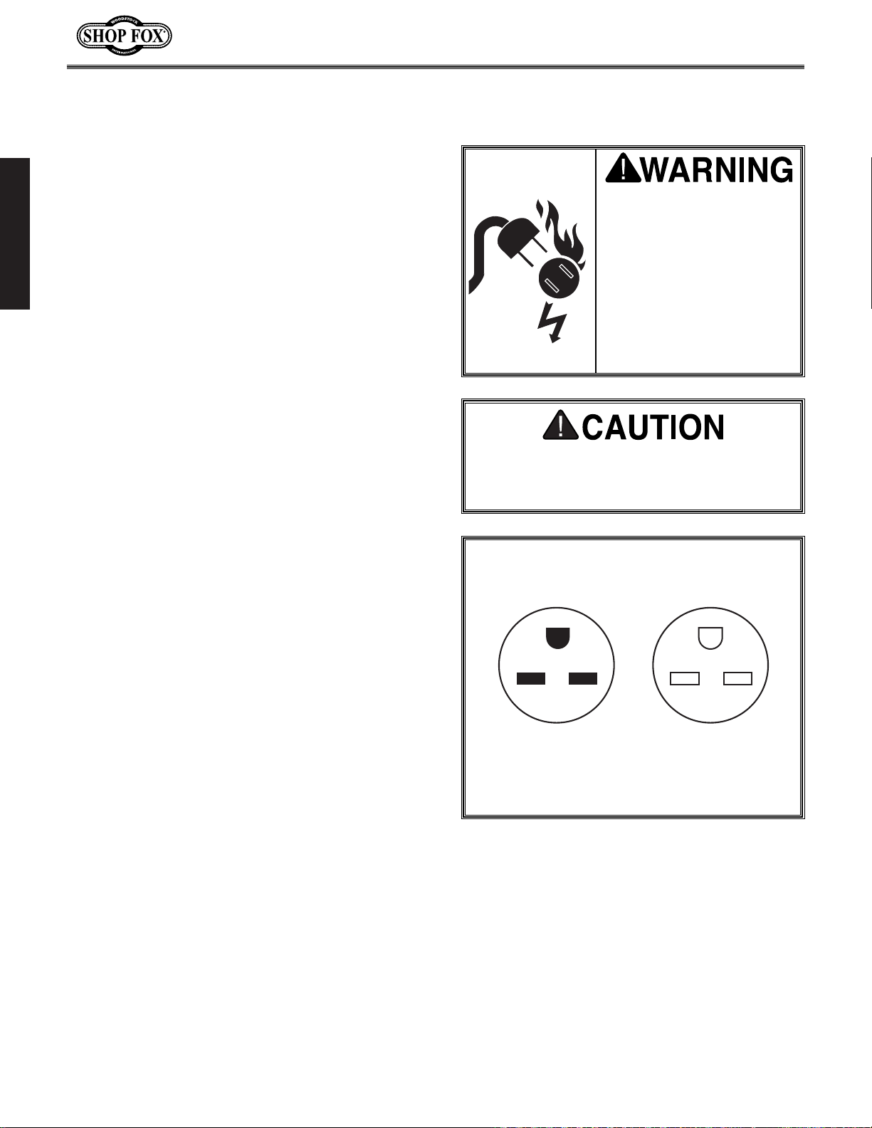
3. Ground all tools. If a machine is equipped with a three-prong plug, it must be plugged into a three-
hole grounded electrical outlet or grounded extension cord. If using an adapter to aid in accommodating a two-hole receptacle, ground using a screw to a known ground.
4. Wear eye protection at all times. Use safety glasses with side shields or safety goggles that meet
the national safety standards, while operating this machine.
5. Avoid dangerous environments. Do not operate this machine in wet or open flame environments.
Airborne dust particles could cause an explosion and severe fire hazard.
6. Ensure all guards are securely in place and in working condition.
7. Make sure switch is in the “OFF” position before connecting power to machine.
8. Keep work area clean, free of clutter, grease, etc.
9. Keep children and visitors away. Visitors should be kept at a safe distance away while operating
unit.
10. Childproof workshop with padlocks, master switches or by removing starter keys.
11. Disconnect machine when cleaning, adjusting or servicing.
Indicates an imminently hazardous situation which, if not avoided, WILL
result in death or serious injury.
Indicates a potentially hazardous situation which, if not avoided, COULD
result in death or serious injury.
Indicates a potentially hazardous situation which, if not avoided, MAY
result in minor or moderate injury, MAY result in property damage.
This symbol is used to alert the user to useful information about proper
operation of the equipment.
NOTICE
Page 7

SAFETY
-5-
12. Do not force the machine. The machine will do a safer and better job if IT does the work.
13. Use the correct tool. Do not force the tool or attachment to do a job for which it was not designed.
14. Wear proper apparel. Do not wear loose clothing, gloves, jewelry, keep long hair tied up, etc.
15. Remove adjusting keys and wrenches. Before turning the machine on, make a habit of checking
that all adjusting keys and wrenches have been removed before turning the machine ON.
16. Use proper extension cord. Examine the extension cord to ensure it is in good condition. Use the
chart below to determine the correct length and gauge of extension cord needed for your particular
needs. The amp rating of the motor can be found on its nameplate. If the motor is dual voltage, be
sure to use the amp rating for the voltage you will be using. If you use an extension cord with an
undersized gauge or one that is too long, excessive heat will be generated within the circuit increasing the chance of a fire or damage to the circuit. Never use an extension cord that does not have a
ground pin and connected ground wire. Immediately replace an extension cord if it shows any signs
of damage.
17. Keep stable footing and balance at all times.
18. Do not leave machine unattended. Wait until it comes to a complete stop before leaving the area.
19. Perform machine maintenance and care. Follow lubrication and accessory attachment instructions
in the manual.
20. Keep machine away from open flame. Operating machines near pilot lights and/or open flames creates a high risk if dust is dispersed in the area. Dust particles and an ignition source may cause an
explosion. Do not operate the machine in high-risk areas, including but not limited to, those mentioned above.
21. If at any time you are experiencing difficulties performing the intended operation, stop using the
machine! Then contact our Service Department or ask a qualified expert how the operation should
be performed.
22. Habits—good and bad—are hard to break. Develop good habits in your shop and safety will become
second-nature to you.
Operating this equipment creates the
potential for flying debris to cause eye
injury. Always wear safety glasses or goggles when operating equipment. Everyday
glasses or reading glasses only have impact
resistant lenses, they are not safety glasses.
Be certain the safety glasses you wear meet
the appropriate standards of the American
National Standards Institute (ANSI).
Length And Gauge
Amp Rating 25ft 50ft 100ft
0-6 #18 #16 #16
7-10 #18 #16 #14
11-12 #16 #16 #14
13-16 #14 #12 #12
17-20 #12 #12 #10
21-30 #10 #10 No
Extension Cord Requirements
Page 8

SAFETY
-6-
Additional Safety Instructions For Sanders
No list of safety guidelines can be complete.
Every shop environment is different. Always
consider safety first, as it applies to your
individual working conditions. Use this and
other machinery with caution and respect.
Failure to follow guidelines could result in
serious personal injury, damage to equipment or poor work results.
1. Always wear a dust mask. Sanding operations create large amounts of fine dust. Some types of dust
may cause allergic reactions or respiratory problems. In addition to wearing a dust mask, always use
a dust collector and overhead air filter for maximum protection.
2. Do not allow your fingers to get pinched between the board and the conveyor belt during feed-
ing. The grip of the conveyor belt may pull the operator’s hand into the machine and cause serious
injury or death. Similarly, do not place hands near the sanding belts during operation.
3. Know the limits of the sander. Do not sand stock thinner than
1
⁄8
" or shorter than 9".
4. Never perform sanding operations with the access doors open.
5. Always inspect stock for staples, nails, dirt or other foreign objects before sanding. These items
may cause damage to your sander or may even be thrown at a high rate of speed from the sander
at the operator.
6. Never allow anyone to stand directly in front or behind the path of the stock as it is being fed
through the sander. The stock may be ejected at a high rate of speed and could cause serious injury
to the operator or bystanders.
7. Treat your sander with respect. Do not force stock into the sander during operation or overload
the sanding drums beyond reasonable limits. Also, only sand natural wood fiber through your sander.
Other materials may damage your machine and open the possibility for operator injury. Keep the
internal components clean and lubricated to ensure that the sander can perform the way it was
intended.
8. Never operate the sander without a working dust collection system. The sander is designed to
properly do its job only when wood dust is being evacuated. The buildup of too much wood dust in
the internal components will cause performance problems and may increase the likelihood of operator injury.
9. Wear the proper clothing during all operation and adjustments. Loose clothing or long hair creates the potential for operator injury because they can easily be caught in the moving parts of the
machine. Roll up loose sleeves, tie back long hair and take any other necessary steps to reduce this
hazard.
Read and understand this
entire instruction manual
before performing any
operations with your
machine. Serious personal
injury may occur if safety
and operational information is not understood and
followed.
Page 9

SAFETY
-7-
Avoiding Potential Injuries
Figure 1. Correct operation.
Figure 2. DO NOT operate without safety glasses/dust mask!
Figure 3. DO NOT stand behind workpiece!
Figure 4. DO NOT operate with door open!
Figure 5. DO NOT allow hand to get pinched in belt!
Page 10
SAFETY
-8-
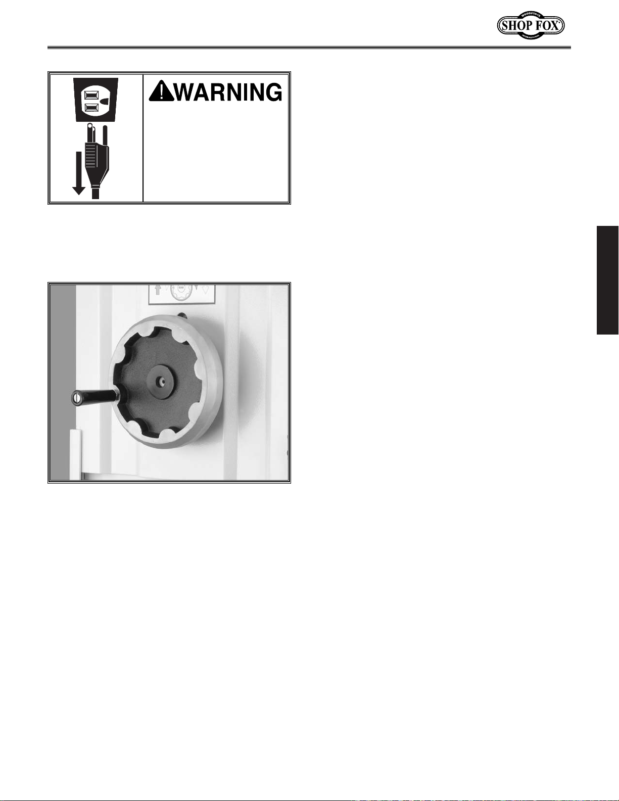
Electrical Requirements
220V Operation
We do not recommend using an extension cord
for 220V equipment. Instead, arrange the placement of your machinery and installed wiring to
eliminate the need for extension cords. If you
must use an extension cord, make sure it is
rated Hard Service (grade S) or better. The
extension cord must always contain a ground
wire and plug pin. Always repair or replace
extension cords when they become worn or
damaged.
Extension Cords
Grounding
This machine must be grounded! The electrical
cord supplied with the Model W1679 does not
come with a 220 volt plug. Use a NEMA-style 630 plug and outlet similar to Figure 6. Make sure
your ground source is verified!
The SHOP FOX
®
W1689 has a 5 HP, 220V single-
phase sanding motor and a
1
⁄4
HP, 220V feed
motor. Both of these motors combined draw
approximately 27.8 amps under load.
Use a 30 amp circuit breaker in a circuit that has
wiring rated to handle this amperage draw.
Keep in mind that a circuit being used by other
machines or tools at the same time will add to
the total load being applied. Add up the load
ratings of all machines on the circuit. If this
number exceeds the rating of the circuit breaker or wiring, use a different circuit.
Figure 6. This is a typical NEMA-style 6-30 plug
and outlet.
DO NOT replace the circuit breaker with
one rated at a higher amperage or damage
to the circuit may occur.
Any electrical outlet and circuit that you plug your
machine into must be
grounded. Never remove
the grounding pin from any
plug and always make sure
all wiring to the machine is
grounded before operating.
Serious injury may occur if
this warning is ignored!
6-30R6-30P
Page 11

ASSEMBLY
-9-
The following is a description of the components
shipped with the SHOP FOX
®
W1689. Lay the
components out in a similar fashion to those in
Figure 7. This will help in identification before
beginning assembly. Should any part be missing,
examine the packaging carefully. If any parts
are missing, find the part number in the back of
this manual and call Woodstock International,
Inc. at 360-734-3482 or e-mail:
tech-support@woodstockint.com
.
Sander ..............................................(1)
Tool Box ............................................(1)
Combination Wrench 8 x 10MM ................(1)
Combination Wrench 11 x 13MM ................(1)
Combination Wrench 12 x 14MM ................(1)
Combination Wrench 17 x 19MM ................(1)
Box Wrench 30 x 37MM ..........................(1)
Phillips Screwdriver ..............................(1)
10-Piece Hex Wrench Set ........................(1)
Door Handles ......................................(2)
Platen ..............................................(1)
Platen Puller ......................................(1)
Handwheel Handle ................................(1)
Sanding Belt #180 ................................(1)
Sanding Belt #240 ................................(1)
Item Qty.
Figure 7. These are the loose parts shipped
with the sander.
Unpacking
Box Contents
The Model W1689 has been carefully packaged
for safe transporting. If you notice the machine
has been damaged, please contact Woodstock
International Service and Support at 1-360-7343482 or send e-mail to:
tech-support@woodstockint.com
.
ASSEMBLY INSTRUCTIONS
Read and understand this
entire instruction manual
before performing any
operations with your
machine. Serious personal
injury may occur if safety
and operational information is not understood and
followed.
The Model W1683 is a
heavy machine at 815
lbs. Use power or
hydraulic equipment to
avoid serious personal
injury or death.
Page 12

ASSEMBLY
-10-
Shop Preparation
• Floor Load: Your sander represents a large
weight load in a small footprint. Most commercial floors are suitable for the sander.
Some residential floors may require additional bracing to support both machine and
operator.
• Working Clearances: Consider existing and
anticipated needs, size of material to be
processed through each machine, and
space for auxiliary stands, work tables or
other machinery when establishing a location for your sander.
• Lighting and Outlets: Lighting should be
bright enough to eliminate shadows and
prevent eye strain. Electrical circuits
should be dedicated or large enough to
handle amperage requirements. Outlets
should be located near each machine so
power or extension cords are clear of hightraffic areas. Observe local electrical codes
for proper installation of new lighting, outlets, or circuits.
Cleaning Machine
The table and other unpainted parts of the
Model W1689 are coated with a waxy grease that
protects them from corrosion during shipment.
For optimum performance from your machine,
make sure you clean all moving parts or sliding
contact surfaces that are coated. Clean this
grease off with a solvent cleaner or citrus-based
degreaser. Do not use chlorine-based solvents—
if you happen to splash some onto a painted surface, you will ruin the finish.
Always make sure that all
entrances to your shop are
locked or that machines
are equipped with safety
lock-out devices to protect
curious children or visitors
from serious injury. Never
allow unsupervised people
in your shop who have not
been fully trained!
Never use flammables
such as gas or other petroleum-based solvents to
clean your machine.
These products have low
flash points and present
the risk of explosion and
severe personal injury!
Never smoke while using
any cleaning solvents.
Smoking may cause explosion or risk of fire when
exposed to these products!
Most solvents used to
clean machinery are
toxic when inhaled or
ingested. When using
these products, work in
a well ventilated area
and keep away from any
potential ignition
sources (pilot lights).
Always dispose of any
waste rags in a sealed
container to make sure
they do not cause fire or
environmental hazards.
Page 13
ASSEMBLY
-11-
Beginning
Although the main components of the SHOP
FOX
®
W1689 are assembled at the factory, some
assembly is required. The following series of
instructions are the recommended sequence
best suited for final assembly.
Tools required that are not included: A high
quality straightedge, a 45˚ angle gauge and an
adjustable wrench.
Handwheel Handle
Install the handle on the handwheel as follows:
1. Make sure that the jam nut is threaded com-
pletely onto the handle.
2. Use a flat-head screwdriver to thread the
handle all the way into the handwheel as
shown in Figure 8.
3. Unthread the handle
1
⁄2 a turn to make the
plastic sleeve loose enough rotate around
the handle freely.
4. Tighten the jam nut down to the handwheel.
Figure 8. Handle installed on handwheel.
Make sure that your
machine is unplugged
during all assembly procedures! If this warning
is ignored, serious personal injury may occur.
Page 14
ASSEMBLY
-12-
Figure 9.
Installing platen.
Figure 10. Platen adjustment knob.
Installing Platen
Install the platen into the sander as follows:
1. Facing the front of the sander, open the left
hand access door with the included door
handle.
2. Directly below the adjustment knob is a
slide housing for the platen. Locate the
slide housing and install the platen so that
the graphite pad is on the left-hand side.
Figure 9 shows the correct insertion of the
platen.
When the platen is inserted correctly, it must
be set even with the sanding belt rollers as follows:
1. Lower the conveyor table down as far as it
will go, so that you have enough room to
work under the sanding belt rollers.
2. Place a straightedge across the bottom of
both sanding belt rollers.
3. Using the platen adjustment knob shown in
Figure 10, position the platen so that it
barely touches the straightedge, and thus,
is even with both sanding belt rollers.
The platen at level position is an important reference point for future operations.
Page 15
ASSEMBLY
-13-
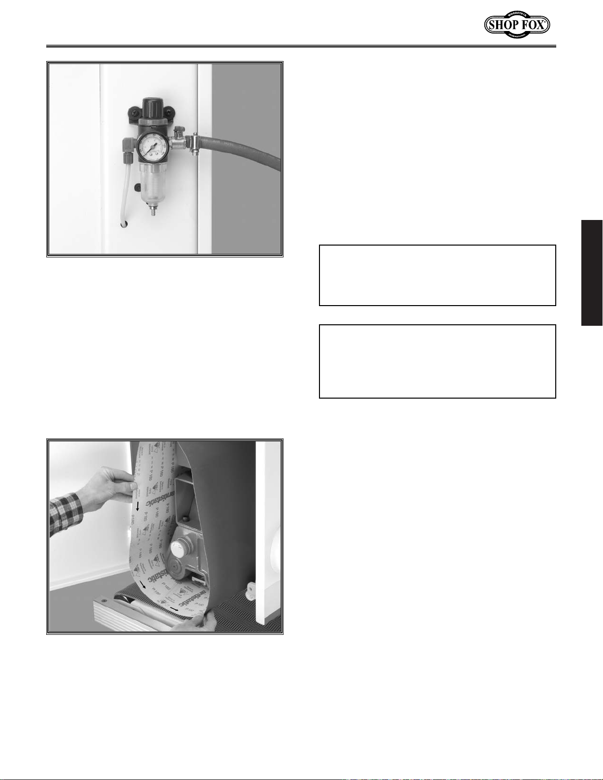
Attaching Air Hose
The regulator on the front of the sander has a
nozzle for attaching the air hose. Connect your
air hose and clamp it in place with a hose clamp
as shown in Figure 11. If you prefer, you can
replace the included air nozzle with a
3
⁄8" male
quick connect air coupling.
When the air hose is installed, regulate the air
pressure to 75 PSI. This is the required operating
pressure for this sander.
Installing
Sanding Belt
The sanding belt must be installed from the left
side of the sander. Before installing, make sure
the protective grease has been cleaned (as
described in “Cleaning Machine” instructions)
from the metal sanding belt rollers.
Pay special attention to the direction of the
arrows on the inside of the sanding belt. These
arrows show the direction that the sanding belt
is designed to rotate during operation. Facing
the inside of the left-hand access door, the
sanding belt will rotate counterclockwise.
Install the sanding belt as shown in Figure 12
and center it on the rollers.
Figure 11. Air hose attached to regulator.
Figure 12. Installing sanding belt over rollers.
The arrows on the inside must point in the
same direction as belt rotation.
DO NOT exceed 75 PSI or damage to the air
system may result!
NOTICE
Keep the air pressure shut off when not in
use to reduce wear and tear on the air system.
NOTICE
Page 16
ASSEMBLY
-14-
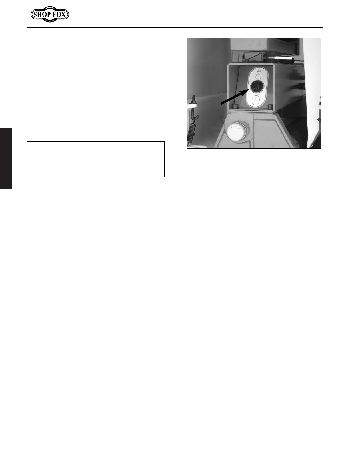
Figure 13. Belt tension switch.
Tensioning Belt
The switch shown in Figure 13 controls the
sanding belt tension. When the air pressure is
connected and the switch is flipped up, the belt
will automatically tighten to the correct tension. Flipping the switch down will immediately
release the belt tension. The belt tension will
only engage while the sander has air pressure.
Likewise, the belt tensioner may not work correctly if the air pressure is not set to the
required 75 PSI.
Pressure Rollers
The pressure rollers are factory set, but we
recommend checking them as follows to minimize the potential for personal injury:
1. Make sure that the sander is unplugged
from the power!
2. Make sure that the platen is even with the
sanding belt rollers before continuing.
3. Obtain a board of uniform thickness that is
at least 24" long. Place the board in the center of the conveyor belt and position it
directly under both the front and rear pressure rollers.
4. The air pressure should be connected and
the sanding belt should be installed and tensioned for this next step. Look underneath
the sanding head at the pressure rollers and
sanding belt. Slowly raise the table and confirm that the board makes contact with
both pressure rollers before it touches the
sanding belt.
If the board DOES NOT make contact with both
pressure rollers before touching the sanding
belt, then the pressure rollers must be adjusted.
Refer to the Adjustments section for step-bystep instructions on how this can be done.
The belt must be tightened before starting
the sander!
NOTICE
Page 17

ASSEMBLY
-15-
Dust Collection
The Model W1689 features a 5" dust port that is
located on top of the machine. Before performing any sanding operations, a working dust collector must be attached to the sander as shown
in Figure 14.
The dust collector that is attached to the
Model 1689 must be able to move 800-1200
CFM at the sander dust port. Make sure that
your dust collector and dust collection system
have the ability to move this volume of dust, or
dust buildup will affect the performance of your
sander.
A fine layer of dust may be present on your
stock as it comes out of the sander. This is normal.
Figure 14. Dust collection hose
attached to dust port.
Always wear a dust mask
in addition to using a dust
collector. This machine
produces sawdust that
may cause allergic reactions or respiratory problems.
DO NOT operate this
machine without an adequate dust collection system. This machine creates
substantial amounts of
wood dust while in operation. Failure to use a dust
collection system can
result in short and longterm respiratory illness.
Page 18

ADJUSTMENTS
-16-
ADJUSTMENTS
Make sure that your
machine is unplugged
during any adjustment
procedures unless
instructed to do different! If this warning is
ignored, serious personal injury may occur!
General Information
The adjustments in this section have been factory set and generally do not need to be performed when you first receive your sander; however, we suggest that you become familiar with
these adjustments before operating your
sander. This information will help you understand the machine better and will prepare you
for the types of adjustments that can be made
in the event of any troubleshooting.
Oscillation Timing
When adjusting the oscillation action of the
sander, the first thing you should do is adjust
the balance of the sanding belt side-to-side
movement. When the timing is right, the belt
will take the same amount of time to move in
one direction, as it moved in the other direction. Time the oscillation as follows:
1. With the sanding belt installed and properly
tensioned, open both access doors on the
upper part of the sander, then turn the
sanding belt ON and determine the oscillation timing status.
• If the oscillation timing is correct the sand-
ing belt will move back and forth evenly,
and no further adjustments to the timing
will be needed.
• If the oscillation is incorrect, the belt will
move faster to one side, then slower to the
other—follow step 4 to adjust; or if the belt
comes off the rollers and immediately stops
the sander—follow steps 3-4 to adjust.
3. If the belt moves too far to one side and
stops the sander, then re-adjust the timing
control knob (shown in Figure 15) approxi-
Always wear safety glasses during operations.
Serious injury may occur
if this is warning is ignored!
Always keep loose
clothing and long hair
secured and away from
moving parts.
Figure 15. Oscillation timing knob.
Keep your hands clear of the sanding belt
when making these adjustments!
Page 19

ADJUSTMENTS
-17-
Oscillation Return
The oscillation return is responsible for keeping
the belt in motion during oscillation. Figure 16
shows the valve that controls the oscillation
return. Adjust the oscillation return as follows:
1. Unplug the power but keep the air pressure
going into the machine.
2. Loosen the belt tension and remove the
sanding belt from the sander.
3. Obstruct the airflow between the air eye
fork (shown in Figure 17) with your finger
until the top sanding roller rotates a small
amount then stops.
Oscillation Speed
The valve shown in Figure 16 controls the speed
of the sanding belt oscillation. For normal operations, the oscillation speed should be set so
that it takes approximately 2 seconds to move
each direction of travel or a total of 4 seconds
to move both directions. The oscillation timing
must be balanced before adjusting the speed!
To increase the speed, turn the valve counterclockwise.
To decrease the speed, turn the valve clockwise.
After the speed has been set, tighten the jam
nut under the valve knob so it will not move.
Experiment with different speeds to see how the
results may affect your finished product. Often,
you may find that certain speeds yield better
results for different varieties of stock.
Always keep loose
clothing and long hair
secured and away from
moving parts.
Figure 16. Oscillation speed and oscillation
return control valves.
Figure 17. Air eye fork.
mately 1⁄2
" to the left or right, loosen the
belt tension, recenter the sanding belt on
the rollers and tighten the belt again. Turn
the sanding belt ON and repeat this step
until the belt will not stop the sander when
oscillating.
4. When the belt is oscillating without stopping, loosen the timing knob and slowly
move it until the belt is moving back and
forth in even intervals. Lock the timing knob
to keep the oscillation consistent.
Speed
Return
Page 20

ADJUSTMENTS
-18-
Figure 18. Limit switch adjustment bolt.
4. Keep the airflow blocked and loosen the
jam nut under the valve knob. Turn the
knob clockwise to close the valve.
5. Mover your finger away from the air eye
fork to resume the airflow. Slowly turn the
valve counterclockwise and watch the top
roller for movement.
6. When the top roller starts moving, continue
turning the valve another
1
⁄2 turn. Tighten
the jam nut to keep the new setting in
place. Avoid opening the knob more than
necessary because this will place excessive
pressure on the air system components.
Always wear safety glasses during operations.
Serious injury may occur
if this is warning is ignored!
Limit Switches
Limit switches are placed on both sides of the
belt to act as emergency stops if the belt travels too far to one side during oscillation. Adjust
the limit switches as follows:
1. Release the belt tension, center the sanding
belt on the top roller, then tension the belt
again.
2. Measure the distance from the edge of the
sanding belt to the rubber coated portion of
the limit switch. When correct, the belt and
the switch should be approximately
1
⁄2"
away from each other. If your measurement
is different than this, the limit switch must
be adjusted.
3. The bolt shown in Figure 18 secures the
limit switch to the frame. Loosen this bolt
and slide the limit switch as necessary until
you achieve the proper
1
⁄2" measurement.
4. Tighten the bolt that secures the limit
switch and repeat the adjustment with the
other side if necessary.
5. Plug the sander back in and turn it ON to
ensure that it is working properly. Repeat
these instructions if necessary.
Make sure that your
machine is unplugged
during any adjustment
procedures unless
instructed to do different! If this warning is
ignored, serious personal injury may occur!
Page 21

ADJUSTMENTS
-19-
Figure 19. Platen depth knob.
Figure 20. Boards placed under pressure rollers
as a gauge.
Platen Depth
Occasionally you will need to “reset” the platen
depth and make it even with the sanding belt
rollers. Set the platen depth as follows:
1. Unplug the sander from the power!
2. Lower the conveyor table down as far as it
will go so that you have enough room to
work under the sanding belt rollers.
3. Place a straightedge across the bottom of
both sanding belt rollers.
4. Using the platen adjustment knob shown in
Figure 19, move the platen so that it bare-
ly touches the straightedge, and thus, is
even with both sanding belt rollers.
Pressure Rollers
The pressure rollers can be adjusted in two
ways—the depth and the tension. For proper
depth, the front pressure roller should be
approximately .040" below the level of the sanding rollers and the rear pressure should be
approximate .020" below the level of the sanding rollers. Adjust the pressure roller depth as
follows:
1. Unplug the sander, but keep air pressure
coming in and have the sanding belt
installed and tensioned for the following
steps.
2. Make two adjustment boards that are 24"
long and are of a uniform thickness.
3. Place each board on each side of the conveyor belt so that they are positioned
directly below the front and back pressure
rollers as shown in Figure 20.
Page 22

ADJUSTMENTS
-20-
Figure 21. Pressure roller adjustment bolts.
4. Raise the pressure rollers above the sanding
belt rollers with the adjustment bolts shown
in Figure 21. The pressure roller adjust-
ment bolts can be locked/unlocked with the
recessed setscrews in the head of the bolt.
For the rear pressure rollers, these bolts are
located in the same position on the back
side of the machine.
5. Make sure that the platen is even with the
sanding belt rollers.
6. Raise the table up until the boards barely
touch the sanding belt. This is an important
reference point. Notice the table hand-
wheel position and make a mental note of
its location for the next adjustment.
7. Turn the table handwheel counterclockwise
1
⁄8thof a turn. This will lower the table
approximately
1
⁄
64". Now lower the rear
pressure roller so that both ends barely
touch the boards.
8. Turn the table handwheel counterclockwise
another
1
⁄8thof a turn. Now lower the front
pressure roller so that both ends just touch
the boards.
The pressure rollers should now be properly set.
Keep in mind that roller tension, besides roller
depth, will also affect the feeding operations.
Page 23

ADJUSTMENTS
-21-
Figure 22. Pressure roller adjustment spring.
Figure 23. Motor mount adjustment nuts.
Pressure Roller
Tension
Pressure roller tension is the downward force
that the pressure rollers place on the workpiece
as it passes through the sander. Too little tension will cause the workpiece to pass unevenly
through the sander and may launch the workpiece from the sander. Too much tension may
cause poor and inconsistent sanding results, as
well as premature wear on the conveyor belt.
Adjust the pressure roller tension as follows:
1. Unplug the sander from the power!
2. Verify that the pressure roller depth is set
correctly.
3. Open both access doors on the upper part of
the sander and locate the tension springs
shown in Figure 22.
4. The position of the nut on the adjustment
bolt controls the spring tension. Turn the
nut clockwise to increase the tension and
counterclockwise to decrease the tension.
V-Belt Tension
The V-belts that drive the sanding rollers must
be tensioned properly for best performance.
Tension the V-belts as follows:
1. Unplug the sander from the power!
2. Remove the cover on the right-hand side of
the lower portion of the sander.
3. The two nuts shown in Figure 23 are
responsible for adjusting the V-belt tension.
Turn both nuts clockwise to tighten the Vbelts, or turn both nuts counterclockwise to
loosen the V-belts.
4. The V-belt is properly tightened when it will
move no more than
3
⁄4" in the center with
moderate pressure from your thumb.
Page 24

ADJUSTMENTS
-22-
Feed Belt Tension
The feed belt tension has been set at the factory and should not need to be adjusted when the
machine is new; however, if at any point you
notice that your feed belt is slipping on the
rollers, it should be tensioned. Tension the
feed belt as follows:
1. Unplug the sander from the power source!
2. Position the emergency brake plate up as
far as it will go, so that it is out of the way
of the tension screws (one is shown in
Figure 24). The back feed roller is not
adjustable, and therefore, no adjustment
screws are located at the back of the
sander.
3. Turn the adjustment bolt clockwise to
increase the tension and turn it counterclockwise to decrease the tension. Adjust
each side evenly so that the tracking does
not become misaligned.
4. When the tension is correct, run the belt for
at least three minutes to check the tracking
before resuming sanding operations.
Feed Belt Tracking
If you notice that the feed belt is tracking more
to one side, turn the feed belt OFF immediately
and adjust the tracking. The belt tracking is
adjusted by using the same adjustment screws
that were used during feed belt tensioning.
Tension the feed belt tracking as follows:
1. Use the adjustment screws to position the
feed belt roller evenly on each side.
Measure the roller shaft location in the
mounting brackets with a caliper or fine
ruler to get each side even.
2. Run the feed belt for at least three minutes
to determine if the tracking is correct. If
the belt does not track evenly, make small
adjustments to the side opposite of the belt
travel and repeat this step until it tracks
evenly.
Figure 24. Feed belt tension screw.
Emergency
Brake Plate
Feed Belt
Tension Screw
Page 25

OPERATIONS
-23-
OPERATIONS
Test Run
Once assembly is complete, the machine is
ready for a test run. The purpose of a test run is
to identify any unusual noises and vibrations, as
well as to confirm that the machine is performing as intended. Perform the test run as fol-
lows:
1. Turn both the sanding and feeding belts ON.
2. Once the machine is running, listen for any
unusual noises. A slow, rhythmic air sound
is normal. The machine should run smooth-
ly with little or no vibrations.
3. If there are any unusual noises or vibrations,
shut the machine off immediately.
4. Unplug the machine and investigate the
source of the noise or vibration. DO NOT
make any adjustments to the machine while
it is plugged in. The machine should not be
run any further until the problems are corrected.
Always wear a dust mask
in addition to using a dust
collector. This machine
produces sawdust that
may cause allergic reactions or respiratory problems.
Always wear safety glasses during operations.
Serious injury may occur
if this is warning is ignored!
Always keep loose
clothing and long hair
secured and away from
moving parts.
Selecting Sandpaper
When selecting sandpaper, keep in mind that
the Model W1689 accepts only 16"W x 48"L belts
similar to those shown in Figure 25.
When deciding which grit of sandpaper to use,
consider the type of work, the species of wood
and the stage of finishing. Use these numbers as
a general guide to sandpaper type:
• 60 Grit....................................Coarse
• 80-100 Grit ..............................Medium
• 120-150 Grit ............................Fine
Experiment with each type of sandpaper on
scrap stock that is the same species as your
workpiece.
For best results, do not increase grit numbers
more than 50 on any successive pass.
Figure 25. Sanding belts.
Page 26

OPERATIONS
-24-
Conveyor Table
Height Adjustments
The conveyor table height adjusts by turning the
handwheel shown in Figure 26.
Also shown is the table height scale that measures the movement of the table. This scale is
marked in both inches and millimeters. The
table height scale can be used as a quick guide
to matching workpiece thickness with table
height.
The conveyor table lock knob shown in Figure
27 allows you to lock the table height after
adjustments have been made.
Feed Speed
The feed belt motor offers speeds of 13 and 16
FPM. Figure 28 points out which sprockets are
responsible for which speeds. Change the feed
belt speeds as follows:
1. Unplug the power from the sander!
2. Remove the feed belt motor cover by taking
out the cap screw that secures it.
3. Loosen the four bolts at the motor mount
and slide the motor up. Pull the chain off of
the sprocket that it is currently on.
4. Place the chain on the next sprocket and
slide the motor down to tighten the chain.
Hold the motor down and tighten the motor
mount bolts at the same time.
5. Replace the motor cover before plugging
sander into power!
Figure 26. Table height handwheel and scale.
Figure 27. Handwheel movement diagram.
Figure 28. Feed motor chain and sprockets.
Table
Height
Scale
Table Height Handwheel
Table Height Lock Knob
13 FPM
16 FPM
Page 27

OPERATIONS
-25-
Using Load Meter
The load meter shown in Figure 29 is an impor-
tant gauge for determining how deep of a cut
the sander can take while you are feeding the
workpiece. The load meter displays the current
amperage draw of the sander. As the depth of
cut increases, so does the amperage draw. Use
this meter for consistent sanding depths and to
avoid overloading your sander.
Never exceed 26 amps on the load meter! This
is the maximum amount that the sander can
safely handle.
Operating Sander
The normal depth of cut is no more than 1⁄64".
This depth is the equivalent of turning the table
height handwheel
1
⁄8thof a turn. DO NOT raise
the table more than
1
⁄8thof a turn on one suc-
cessive pass. Attempting to remove too much
material can cause workpiece burning, premature paper wear, paper tearing and undesirable
finished results. Basic sanding operations are
performed as follows:
1. Put on safety glasses and a dust mask, and
start the dust collector.
2. Make the thickness adjustment slightly larger than your workpiece.
Figure 29. Load meter.
Emergency Stop
Figure 30. Emergency stop plate.
The emergency stop shown in Figure 30 is provided to stop the sander quickly. The emer-
gency stop is engaged as follows:
1. Push the bottom of the emergency stop
plate as far as it will go.
2. Hold the emergency stop plate until the
sander has come to a complete stop.
For best results, feed each piece through the
sander two or three times without adjusting
the depth of cut. Turn the workpiece 180˚
and feed it through two or three more times
at this same depth. As always, use your best
judgement. If you no longer hear the sanding belt making contact with the workpiece
on successive cuts, then no further passes are
needed at that depth.
Quick Tip
Page 28

OPERATIONS
-26-
Adjusting Platen
The adjustable platen allows you to achieve different results from your sander, depending on
how it is positioned. To move the platen up or
down, use the knob shown in Figure 32 and
gauge the depth/height by using the scale on
the knob. The three possible platen positions
are as follows:
Platen Up — The platen is moved above the
sanding rollers. The rollers then act like a drum
sander and allow for increased stock removal. In
this position, the ideal belt grit is #100 or coarser. The scratch pattern in this mode will be
short and deep, relative to grit size.
Platen Even — The platen is set even with the
sanding rollers. The rollers act together with the
platen pressure to achieve intermediate or final
finishing. In this position, the ideal belt grit is
between #100 and #180. The scratch pattern in
this position is moderate, relative to grit size.
Platen Down — The platen is moved below the
sanding rollers. With the platen down, the workpiece contact with the sandpaper is only made
at the platen. This position is used for fine finishing, sanding repairs, or sanding lacquer. The
ideal belt grit is #180 or finer. Generally sanding
with the platen down will remove .004" or less.
The scratch pattern in this position will be long
and shallow, relative to grit size.
Figure 32. Platen depth knob.
The platen depth should never be more
than .2mm below the sanding belt rollers or
sanding belt damage/stretching may occur.
This depth can be determined by watching
the scale on the platen knob. (.2mm is the
equivalent of one full turn of the knob.)
NOTICE
3. Feed the workpiece as shown in Figure 31.
4. Adjust the table height while watching the
load meter— remember not to exceed 26
amps!
5. When you achieve a good cut, lock the table
in place and pass the workpiece through the
sander again.
Figure 31. Operator feeding workpiece in
correct position.
Page 29

MAINTENANCE
-27-
MAINTENANCE
Lubrication
Since all bearings are shielded and permanently
lubricated, simply leave them alone until they
need to be replaced. Do not lubricate them.
For other items on this machine, lubricate the
items shown in Figure 33-35. Before applying
lubricant, wipe the area clean.
Your goal is to achieve adequate lubrication.
Too much lubrication will attract dirt and sawdust. These parts of your machine could lose
their freedom of movement as a result.
Regular periodic maintenance on your Model
W1689 will ensure its optimum performance.
Make a habit of inspecting your machine each
time you use it. Check for the following condi-
tions and repair or replace when necessary:
• Loose mounting bolts.
• Worn switch.
• Worn or damaged cords and plugs.
• Damaged drive belt.
• Any other condition that could hamper the
safe operation of this machine.
• Check the entire air system for leaks.
General
Make sure that your
machine is unplugged
during any maintenance
procedures except
where instructed otherwise! If this warning is
ignored, serious personal injury may occur.
Figure 33. Clean and lubricate feed speed chain
with chain lubricant monthly or as needed.
Figure 34. Lubricate table rack with a light
lithium grease monthly or sooner if needed.
Figure 35. Lubricate table column often with
mineral oil.
Page 30

MAINTENANCE
-28-
The filters on the two regulators need to be
emptied and cleaned whenever they get more
than half full. The inside filter shown in Figure
37 will need service more frequently than the
filter on the front of the machine.
Servicing Filters
The graphite pad on the platen will eventually
wear out with use. Replace the graphite sheet
as follows:
1. Remove the platen with the platen puller
tool (shown in Figure 38).
2. Remove the screws and the clamp bar to
separate the graphite pad from the platen.
3. Install the new graphite pad, making sure
that it is wrapped in the same direction as
the old pad, and re-install the clamp bar
and screws.
Platen Graphite
To increase working life of your sanding belts,
we recommend that you routinely clean them
with Pro-Stik
®
Cleaning Pads (shown in Figure
36).
To clean the belts, simply set your table to the
thickness of the cleaning pad and run the pad
through the sander two or three times. DO NOT
take too deep of a cut. The belt should just
barely touch the cleaning pad!
Clean sanding belts whenever they decrease in
performance due to heavy loading.
Cleaning Belts
Figure 36. Pro Stik®cleaning pad.
Figure 38. Platen puller tool.
Figure 37. Check this filter often for service.
Page 31

MAINTENANCE
-29-
Figure 39. Pull casting off of roller ends.
Figure 40. Remove large roller nut.
Figure 41. Remove front sanding roller.
Changing V-Belts
Check the V-belts periodically to check for signs
of glazing, cracking or fraying. If any of these
conditions are present, change both V-belts.
Change the V-belt as follows:
1. Unplug the sander from the power and
shut off the air pressure!
2. Loosen the top nut (turn counterclockwise)
on the motor adjustment bolt. See page 21
for motor adjustment controls. Turn the
bottom nut counterclockwise (or pry motor
up) to loosen and remove the V-belts.
4. In order to take the V-belts off of the roller
pulleys, the rollers must be removed from
the sander. Open both access doors on the
upper part of the machine. At the left-hand
access side, remove the platen knob by
loosening the setscrew near its dial.
5. Remove the two setscrews that secure the
dial plate to the casting and then remove
the two large cap screws that secure the
top of the casting.
6. Pull the casting off of the roller ends as
shown in Figure 39.
7. At the other side of the machine (the righthand side from the front), remove the large
nut shown in Figure 40. The roller may turn
if not held from the other side. This secures
the other end of the front roller shaft to the
sander body.
8. Now, move back to the left-hand side of the
machine and carefully pull out the front
sanding belt roller as shown in Figure 41.
The V-belts can now be easily removed.
9. Install the new V-belts in the reverse order
of removal. To make this process easier,
have a helper hold the V-belts up at the
other side of the sander when you re-install
the roller. When you retighten the large
roller shaft nut, have your helper stand at
the other side of the sander to keep the
roller from turning.
Page 32

MAINTENANCE
-30-
Figure 42. Brake assembly.
Figure 43. Brake caliper removed for access to
brake pads.
Servicing Brake
Any type of foreign material on the brake rotor
creates the potential for improper performance.
Check the brake rotor (shown in Figure 42) reg-
ularly to make sure it is clean. If it needs cleaning, only use automotive brake parts cleaner
and a dry rag. DO NOT use water!
The brake pads (shown in Figure 43) will eventually need to be replaced. Check the brake
pads for replacement as follows:
1. Unplug the sander from the power source
and shut off the air pressure!
2. Remove the motor cover to access the brake
components.
3. The brake pads are made up of a metal
plate and a composite pad. Measure the
thickness of each pad with a fine ruler. If
either of the pads is below
1
⁄
8", then
replace both.
Replace the brake pads as follows:
1. Unplug the sander from the power source
and shut off the air pressure!
2. Remove the caliper from the mounting
bracket. It is held in place by hex nuts and
snap rings on each mounting pin. You may
need to remove the air line to the caliper to
relieve any built up pressure.
3. Remove the cap screws that hold the brake
pads to the caliper. One of these can only
be reached if the caliper is disassembled.
4. Remove the brake rotor and have it professionally surfaced at an automotive or
machine shop. Clean the rotor with automotive brake parts cleaner and handle it with
a dry rag when installing.
5. To finish the job, install the new brake
pads, reassemble and mount the caliper,
and reconnect the air line.
Brake
Rotor
Brake
Caliper
Brake Pads
Page 33

MAINTENANCE
-31-
Troubleshooting
SYMPTOM
Motor will not start.
Motor will not start; fuses or
circuit breakers blow.
Motor overheats.
Motor stalls (resulting in blown
fuses or tripped circuit).
Machine slows when operating.
Loud, repetitious noise coming
from machine
Machine is loud, overheats or
bogs down in the cut.
Edges of wood are rounded.
Uneven thickness from left to
right of board.
Workpiece slips on feed belt.
Straight strip of notches on
workpiece.
Snake shaped marks on workpiece.
POSSIBLE CAUSE
1. Low voltage.
2. Open circuit in motor or loose connections.
1. Short circuit in line cord or plug.
2. Short circuit in motor or loose connections.
3. Incorrect fuses or circuit breakers
in power line.
1. Motor overloaded.
2. Air circulation through the motor
restricted.
1. Short circuit in motor or loose connections.
2. Low voltage.
3. Incorrect fuses or circuit breakers
in power line.
4. Motor overloaded.
1. Feed rate too high.
2. Depth of cut too great.
1. Pulley set screws or keys are missing or loose.
2. Motor fan is hitting the cover.
3. V-belt is defective.
1. Excessive depth of cut.
2. Dull sanding belt.
1. Excessive depth of cut.
1. Feed table not parallel to sanding
roller.
2. Feed belt is worn.
1. Pressure rollers set too high.
2. Dirty feed belt.
3. Feed belt is worn.
1. Pressure rollers are dirty or damaged.
1. Sanding belt damaged or dirty.
HOW TO REMEDY
1. Check power line for proper voltage.
2. Inspect all lead connections on motor for loose or open connections.
1. Inspect cord or plug for damaged insulation and shorted
wires.
2. Inspect all connections on motor for loose or shorted terminals or worn insulation.
3. Install correct fuses or circuit breakers.
1. Reduce load on motor.
2. Clean out motor to provide normal air circulation.
1. Inspect connections on motor for loose or shorted terminals
or worn insulation.
2 Correct the low voltage conditions.
3. Install correct fuses or circuit breakers.
4. Reduce load on motor.
1. Feed workpiece slower.
2. Reduce depth of cut.
1. Inspect keys and set screws. Replace or tighten if necessary.
2. Tighten fan or shim cover.
3. Replace V-belt. See Maintenance section.
1. Decrease depth of cut.
2. Replace sanding belt.
1. Reduce depth of cut.
1. Adjust the table.
2. Replace feed belt.
1. Lower pressure rollers.
2. Clean feed belt.
3. Replace feed belt.
1. Clean or repair pressure rollers.
1. Clean or replace sanding belt.
Page 34

MAINTENANCE
-32-
Troubleshooting
SYMPTOM
Lines across width of workpiece.
Glossy spots or streaks on
workpiece.
Sanding belt clogs quickly.
Sanding belt does not tension
correctly; rollers slip under
belt.
Sanding belt runs off to one
side, stopping the sander.
Sanding belt will not start.
Poor, non-aggressive sanding
results.
Conveyor belt not tracking in
center.
Conveyor belt slipping.
Emergency brake stops slow.
Grinding noise when braking.
POSSIBLE CAUSE
1. Sanding belt seam is open or damaged.
1. Worn sanding belt.
2. Rear pressure roller too low.
1. Sanding belt grit too small for particular job.
2. Excessive depth of cut.
3. Wood is too moist.
1. Low air pressure.
2. Air leaks in system.
1. Air eye fork clogged.
2. Oscillation return valve closed.
3. Oscillation timing incorrect.
1. Sanding belt is not tensioned.
2. Limit switches engaged.
3. Emergency stop plate engaged.
1. Platen adjusted incorrectly, above
bottom surface level of lower sanding rollers.
2. Sanding belt loaded with sawdust.
3. Sanding belt worn out.
1. Conveyor rollers moved out of
adjustment.
1. Conveyor rollers have incorrect
tension.
2. Conveyor rollers contaminated with
dirt or dust.
1. Air pressure incorrect.
2. Air leak in system.
3. Brake rotor contaminated with oil.
4. Brake pads worn out.
1. Brakes severely worn out.
HOW TO REMEDY
1. Repair or replace sanding belt.
1. Replace sanding belt.
2. Raise rear pressure roller. (See warning in Pressure Roller
section!)
1. Replace with a coarser grit sanding belt.
2. Reduce depth of cut.
3. Allow wood to dry out.
1. Adjust air pressure to 75 PSI at primary regulator.
2. Inspect all hoses and connections for leaking air; use water
on suspected area to detect bubbles.
1. Clean the intake hole on the air eye fork.
2. Open valve.
3. Adjust oscillation timing.
1. Tension sanding belt.
2. Center sanding belt so it is not touching the limit switches.
3. Make sure emergency stop switch is released.
1. Adjust platen on the same plane as, or lower than, bottom
surface level of lower rollers.
2. Clean sanding belt to unload sawdust.
3. Replace sanding belt with a new one.
1. Re-adjust conveyor rollers.
1. Adjust conveyor rollers to increase tension.
2. Clean conveyor rollers.
1. Adjust air pressure to 75 PSI.
2. Find and fix air leaks.
3. Clean brake rotor with automotive brake parts cleaner.
4. Replace brake pads.
1. Replace brake pads, have rotor turned (possibly replaced).
Page 35

220 Volt Single Phase
MAIN MOTOR
4
1
3
2
BELT
LIMIT
SWITCH
4
1
3
2
EMERGENCY STOP
LIMIT SWITCH
4
1
1
2
3
4
5
6
FEED BELT MOTOR
1
4
5
2
3
6
3
2
12 13 3 3 5 5 U2
V2
W2
U1
V1
W1
Page 36

D
I
C
N
A
I
T
R
O
E
R
W
O
P
X1 X2
E
D
E
F
21
22
B
E
P
L
O
T
T
S
220 Volt Single Phase
E
E
D
F
X2
X1
21
22
B
T
E
R
L
A
T
T
S
N
A
D
S
I
N
G
B
P
E
O
L
T
T
S
14 13
13 14
14 13
21 22
2 3 5 6 8 9 10 11 14 15
X2
X1
21
22
N
A
D
S
I
N
G
B
T
E
R
L
A
T
T
S
E
R
T
13 14
21 22
E
S
T
R
E
S
E
14 13
Page 37

220 Volt Single Phase
-35-
220V POWER
TO REMAIN BLANK
R S T
TO EMERGENCY
THIS TERMINAL
STOP LIMIT
12 13 3 3 5 5 U2
2 3 5 6 8 9 10 11 14 15
TO BELT
LIMIT SWITCHES
TO ELECTRICAL
SWITCH PANEL
TO FEED
MOTOR
W2
V2
TO MAIN MOTOR
U1
V1
W1
2A FUSES
1L13L25
CN 25
2T14T26
L3
T3
23
21
FN1853-39
RESET
26
29
31
A(R.C.)
1L13L25
CN11
2T14T26
13
NC
L3
T3
RESET
1.7
1.9
1.5
1.3
2.1
A(R.C.)
FN1853-39
14
NC
1L13L25
CN11
2T14T26
13
NC
L3
T3
14
NC
Page 38

PARTS
-36-
The following pages contain parts diagrams/lists
and a warranty card for your SHOP FOX
®
Model
W1689.
If you need parts or help in assembling your
machine, or if you need operational information, we encourage you to call our Service
Department. Our trained service technicians will
be glad to help you.
If you have comments dealing specifically with
this manual, please write to us using the address
in the General Information. The specifications,
drawings, and photographs illustrated in this
manual represent the Model W1689 as supplied
when the manual was prepared. However, due
to Woodstock International, Inc.’s policy of continuous improvement, changes may be made at
any time with no obligation on the part of
Woodstock International, Inc. Whenever possible, though, we send manual updates to all owners of a particular tool or machine that have registered their purchase with our warranty card.
Should you receive one, add the new information to this manual and keep it for reference.
We have included some important safety measures that are essential to this machine’s operation. While most safety measures are generally
universal, we remind you that each workshop is
different and safety rules should be considered
as they apply to your specific situation.
We recommend you keep this manual for complete information regarding Woodstock
International, Inc.’s warranty and return policy.
Should a problem arise, we recommend that you
keep your proof of purchase with your manual.
If you need additional technical information
relating to this machine, or if you need general
assistance or replacement parts, please contact
the Service Department at 1-360-734-3482 or email: tech-support@woodstockint.com
.
Additional information sources are necessary to
realize the full potential of this machine. Trade
journals, woodworking magazines, and your
local library are good places to start.
The Model W1689 is specifically designed for
sanding operations. DO NOT MODIFY AND/OR
USE THIS MACHINE FOR ANY OTHER PURPOSE.
MODIFICATIONS OR IMPROPER USE OF THIS
TOOL WILL VOID THE WARRANTY. If you are
confused about any aspect of this machine, DO
NOT use it until all your questions have been
answered.
CLOSURE
Operating this equipment creates the potential for flying debris to cause eye injury.
Always wear safety glasses or goggles when
operating equipment. Everyday glasses or
reading glasses only have impact resistant
lenses, they are not safety glasses. Be certain the safety glasses you wear meet the
appropriate standards of the American
National Standards Institute (ANSI).
As with all power tools, there is danger
associated with the Model W1689. Use the
tool with respect and caution to lessen the
possibility of mechanical damage or operator injury. If normal safety precautions are
overlooked or ignored, injury to the operator or others in the area is likely.
Page 39

PARTS
-37-
1 XPWR1214 COMBO WRENCH 12/14MM
2 X1689002 BOX WRENCH 30/37MM
3 X1689003 PHILLIPS SCREWDRIVER
4 X1689004 TOOL BOX
5 X1689005 ACCESS DOOR HANDLE
6 X1689006 PLATEN TOOL
7 XPWR1719 COMBO WRENCH 17/19MM
8 XPWR1113 COMBO WRENCH 11/13MM
9 XPWR810 COMBO WRENCH 8/10MM
10 X1689010 ALLEN WRENCH SET (10)
REF PART # DESCRIPTION
REF PART # DESCRIPTION
W1689 Parts & Replacement Items
1
2
3
4
5
7
9
8
6
10
Page 40

PARTS
-38-
154
124
160
128
126
157
123
161
127
153
158
155
122
152
150
121
119
149
42
118
120
148
117
143
147
114
116
142
146
144
113
145
115
139
109
108
140
137
125
129
138
156
130
107
102
132
101
103
131
104
136
133
106
105
135
159
134
162
110
141
111
112
Page 41

PARTS
-39-
REF PART # DESCRIPTION REF PART # DESCRIPTION
101 X1689101 QUILL BASE
102 XPLW06M LOCK WASHER 10MM
103 X1689103 WORM GEAR SHAFT
104 XP6203ZZ BEARING 6203-ZZ
105 X1689105 BUSHING
106 XPR18M RETAINING RING S17
107 X1689107 RACK
108 X1689108 CONVEYOR SUPPORT FRAME
109 XPLW04M LOCK WASHER 8MM
110 X1689110 HANDWHEEL
111 XPW03M FLAT WASHER 6MM
112 X1689112 HANDLE M10-1.5 x 20
113 X1689113 SETTING SHAFT
114 XPSS09M SETSCREW M8-1.25 X 20
115 XPSB62M CAP SCREW M10-1.5 X 12
116 XPW06M FLAT WASHER 12MM
117 X1689117 BRAKE PIN
118 XPLW06M LOCK WASHER 10MM
119 X1689119 BRAKE CALIPER
120 XPS14M CAP SCREW M6-1.0 X 12
121 X1689121 BRAKE
122 XPS47M PHLP HD SCR M6-1.0 X 25
123 X1689123 TOP COVER
124 X1689124 PLASTIC CONNECTOR
125 XPB501M HEX BOLT M10-1.5 X 30
126 X1689126 BRAKE ROTOR
127 XPSB75M CAP SCREW M10-1.5 X 18
128 XPSS13M SETSCREW M10-1.5 X 12
129 X1689129 MACHINE BASE
130 XPSB64M CAP SCREW M10-1.5 X 25
131 X1689131 LOCKING HANDLE M10-1.5 x 50
132 XP51102 BEARING 51102
133 XPR34M RETAINING RING R40
134 XPSB64M CAP SCREW M10-1.5 X 25MM
135 X1689135 WORM GEAR
136 X1689136 GEAR SHAFT
137 X1689137 QUILL
138 XPSB74M CAP SCREW M6-1.0 X 18
139 XPSB12M CAP SCREW M8-1.25 X 40
140 XPSB12M CAP SCREW M8-1.25 X 40
141 XPS24M PHLP HD SCR M6-1.0 X 10
142 X1689142 MACHINE BASE COVER
143 X1689143 MOTOR BASE
144 X1689144 LOCK BUSHING
145 XPW04M FLAT WASHER 10MM
146 X1689146 ADJUSTABLE SCREW
147 XPN09M HEX NUT M12-1.75
148 X1689148 EXT RETAINING RING 13MM
149 XPN02M HEX NUT M10-1.5
150 X1689150 BRAKE PAD
151 X1689151 SPRING
152 X1689152 PLATE
153 X1689153 DIAPHRAGM
154 XPS20M PHLP HD SCR M5-.08 X 15
155 X1689155 SPINDLE MOTOR 5HP
156 XPLW06M LOCK WASHER 10MM
157 XPLW06M LOCK WASHER 10MM
158 X1689158 MOTOR PULLEY
159 X1689159 QUILL COVER
160 XPS47M PHLP HD SCR M6-1.0 X 25
161 XPVA78 BELT A78
162 X1689162 MACHINE ID/WARNING LABEL
Page 42

PARTS
-40-
236
REF PART # DESCRIPTION
REF PART # DESCRIPTION
201 X1689201 ROLLER BRACKET L
202 XPLW04M LOCK WASHER 8MM
203 XPSB40M CAP SCREW M8-1.25 X 35
204 XPLW04M LOCK WASHER 8MM
205 X1689205 LIMIT SWITCH BASE
206 XPS14M PHLP HD SCR M6-1.0 X 12
207 XPW05M FLAT WASHER 4MM
208 XPN04M HEX NUT M4-0.07
209 XPRP03M PIN 5 X 20MM
210 XP6305ZZ BEARING 6305-ZZ
211 XPSS39M SETSCREW M10-1.5 X 50
212 XPLW04M LOCK WASHER 8MM
213 X1689213 LIMIT SWITCH
214 X1689214 MAIN ROLLER
215 X1689215 MOTOR PANEL
216 XPR11M RETAINING RING S25
217 XPSB74M CAP SCREW M6-1.0 X 18MM
218 X1689218 CHAIN WHEEL 19T X 24T
219 X1689219 CHAIN
3
⁄8" X 48PC
220 XPSB37M CAP SCREW M6-1.0 X 50
221 XPLW04M LOCK WASHER 8MM
222 XPW01M FLAT WASHER 8MM
223 XPLW04M LOCK WASHER 8MM
224 X1689224 CONVEYOR BELT 380 X 1620
225 X1689225
CONVEYOR SUPPORT FRAME
226 X1689226 ROLLER BRACKET R
227 XPB07M HEX BOLT M8-1.25 X 25
228 X1689228 BRASS ROLLER
229 XPN03M HEX NUT M8-1.25
230 XPW03M FLAT WASHER 6MM
231 XPS48M PHLP HD SCR M4-.07 X 50
232 X1689232 E-BRAKE PANEL
233 XPR11M RETAINING RING S25
234 X1689234 CONVEYOR AXLE
235 X1689235 CONVEYOR ROLLER
236 X1689236 BEARING SEAT
237 XPB09M HEX BOLT M8-1.25 X 20
238 XPR25M RETAINING RING R47
239 XPK60M KEY 8 X 8 X 15MM
240 XP6205ZZ BEARING 6205-ZZ
241 X1689235 BEARING COVER
242 X1689237 BUSHING
243 X1689243 FEED MOTOR
1
⁄4 HP
244 X1689244 ROLLER CHAIN COVER
245 XPN03M HEX NUT M8-1.25
246 XPB26M HEX BOLT M8-1.25 X 30
247 XPB09M HEX BOLT M8-1.25 X 20
248 XPSS02M SETSCREW M6-1.0 X 6
249 XP6204ZZ BEARING 6204-ZZ
250 X1689250 CHAIN WHEEL 12T, 14T
251 XPSS40M SETSCREW M6-1.0 X 66
249
238
214
239
215
240
245
243
221
241
216
217
222
242
246
251
223
218
248
250
247
220
244
241
229
204
205
225
228
237
212
201
202
227
209
203
231
207
226
208
213
233
224
230
206
234
235
211
210
232
Page 43

PARTS
-41-
312
354
314
355
344
303
343
310
381
315
302
349
351
311
346
305
308
350
309
348
306
307
347
313
301
342
361
345
320
352
360
304
341
353
319
359
318
358
317
357
316
356
324
365
329
369
325
328
366
368
327
337
326
378
370
379
338
367
372
339
371
330
377
335
331
321
333
373
332
375
362
334
374
322
376
336
340
380
364
323
363
Page 44

PARTS
-42-
REF PART # DESCRIPTION
REF PART # DESCRIPTION
301 XPLW06M LOCK WASHER 10MM
302 X1689302 SWITCH PLATE
303 XPLW06M LOCK WASHER 10MM
304 X1689304 COVER
305 XPLW04M LOCK WASHER 8MM
306 X1689306 FORK
307 XPS14M PHLP HD SCR M6-1.0 X 12
308 XPSS02M SETSCREW M6-1.0 X 6MM
309 XPLW04M LOCK WASHER 8MM
310 X1689310 TOP ROLLER SUPPORT
311 XPSS41M SETSCREW M8-1.25 X 18
312 XPSB26M CAP M6-1.0 X 12MM
313 X1689313 ECCENTRIC SHAFT
314 XP6205ZZ BEARING 6205-ZZ
315 X1689315 TOP ROLLER SHAFT
316 X1689316 DIAPHRAGM
317 X1689317 PLATE
318 X1689318 SPRING
319 XPS06M PHLP HD SCR M5-.08 X 20
320 XPN02M HEX NUT M10-1.5
321 XPR11M RETAINING RING S25
322 XP6005ZZ BEARING 6005-ZZ
323 X1689323 ROLLER SHAFT
324 XPR11M RETAINING RING S25
325 XP6005ZZ BEARING 6005-ZZ
326 X1689326 ROLLER SHAFT
327 X1689327 ROLLER BASE
328 XPSB04M CAPSCREW M6-1.0 X 10
329 XPSS02M SETSCREW M6-1.0 X 6
330 X1689330 CONNECTION COUPLING
331 X1689331 SUPP WORM GEAR SHAFT
332 X1689332 GRAPHITE BASE R
333 X1689333 GEAR BUSHING
334 XPB03M HEX BOLT M8-1.25 X 16
335 X1689335 PLATEN (FEMALE)
336 XPSB58M CAP SCREW M8-1.25 X 12
337 X1689337 CARBON GRAPHITE
338 XPW05M FLAT WASHER 4MM
339 X1689339 LINING 30 X 415MM
340 XPN28M HEX NUT M20-2.5
341 X1689341 CONTACT BASE ROLLER
342 XPSB72M CAP SCREW M10-1.5 X 30
343 XPW04M FLAT WASHER 10MM
344 XPSB72M CAP SCREW M10-1.5 X 30
345 XPS02M PHLP HD SCR M4-.07 X 12
346 XPB07M HEX BOLT M8-1.25 X 25
347 XPW03M FLAT WASHER 6MM
348 X1689348 CYLINDER ROLLER FRAME
349 X1689349 SUPPORT TUBE
350 XPSB76M CAP SCREW M8-1.25 X 18MM
351 XPLW04M LOCK WASHER 8MM
352 X1689352 TOP ECCENTRIC FRAME
353 X1689353 KNOB BOLT M8 X 55
354 XPR11M RETAINING RING S25
355 X1689355 TOP ROLLER
356 X1689356 TOP COVER
357 XPS14M PHLP HD SCR M6-1.0 X 12
358 X1689358 SHAFT
359 X1689359 BOTTOM COVER
360 XPR05M EXT RETAINING RING 15MM
361 X1689361 OSCILLATION SQUARE
362 XPR25M RETAINING RING R47
363 X1689363 CONTACT ROLLER
364 X1689364 SLEEVE
365 XPR25M RETAINING RING R47
366 X1689366 SUPPORT ROLLER
367 X1689367 BUSHING
368 X1689368 MICROMETER BASE
369 X1689369 MICROMETER
370 X1689370 MAIN WORM GEAR SHAFT
371 XPSS01M SETSCREW M6-1.0 X 10
372 X1689372 GRAPHITE BASE L
373 X1689373 WORM GEAR
374 XPLW04M LOCK WASHER 8MM
375 X1689375 VERT MICROMETER SCREW
376 XPW01M FLAT WASHER 8MM
377 X1689377 PLATEN (MALE)
378 X1689378 SET PLATE
379 XPS38M PHLP HD SCR M4-.07 X 10
380 XPLW07M LOCK WASHER 20MM
381 X1689381 SANDING BELT
Page 45

PARTS
-43-
447
REF PART # DESCRIPTION REF PART # DESCRIPTION
401 X1689401 ACCESS DOOR RH
402 X1689402 LOCK
403 X1689406 LOAD METER
404 XPS531M PHLP HD SCR M6-1.0 X 35
405 XPLW03M LOCK WASHER 6MM
406 X1689406 TILTING ARM
407 X1689407 POWER INDICATOR
408 X1689408 START BUTTON
409 X1689409 STOP BUTTON
410 X1689410 EMERGENCY STOP BUTTON
411 X1689411 PRESSURE ROLLER
412 X1689412 SPECIAL NUT M8-1.25
413 X1689413 PLASTIC CONNECTOR L6-
1
⁄8"
414 X1689414 SILENCER
1
⁄8"
415 X1689415 LINING
416 XPS02M PHLP HD SCR M4-.07 X 12
417 XPS06M PHLP HD SCR M5-.08 X 20
418 X1689418 PLATE
419 X1689419 BOTTOM ALUMINUM COVER
420 X1689420 CUP
1
⁄4"
421 X1689421 PLASTIC CONNECT C6-
1
⁄4"
422 X1689422 MACHINE FRAME403
423 X1689423 ACCESS DOOR LH
424 X1689424 OPERATING PANEL
425 X1689425 PRESSURE ROLLER FRAME
426 XPSB06M CAPSCREW M6-1.0 X 25
427 XPSS26M SETSCREW M5-08 X 6MM
428 X1689428 SPRING HOOK
429 XPN03M HEX NUT M8-1.25
430 XPR01M RETAINING RING S10
431 XP6001ZZ BEARING 6001-ZZ
432 X1689432 PRESSURE SHAFT
433 XPSS42M SETSCREW M8-1.25 X 50
434 X1689434 SWITCHING VALVE
1
⁄8"
435 X1689435 PLASTIC CONNECTOR C6-
1
⁄8"
436 XPS49M PHLP HD SCR M3-.5 X 5
437 X1689437 TOP ALUMINUM COVER
438 X1689438 PLASTIC CONNECT M6 X
1
⁄4"
439 X1689439 DIAPHRAGM
440 X1689440 PLASTIC CONNECT
1
⁄8" X 1⁄8"
441 X1689441 CONNECTOR
1
⁄4"
442 X1689442 SPRING
443 XPW01M FLAT WASHER 8MM
444 X1689444 SET PIN
445 X1689445 BEARING COVER
446 X1689446 SPACER
447 X1689447 LABEL-UNPLUG POWER
448 X1689447 LABEL-KEEP DOOR CLOSED
449 X1689449 LABEL-SAFETY GLASSES
450 X1689450 LABEL-READ MANUAL
402
448
423
402
406
426
405
445
431
411
432
427
430
428
442
444
429
443
425
439
419
418
440
421
412
420
422
403
433
441
449
410
450
408
401
409
434
415
417
437
407
404
413
414
446
416
424
404
435
436
438
Page 46

PARTS
-44-
REF PART # DESCRIPTION
REF PART # DESCRIPTION
501 XPS12M PHLP HD SCR M3-.5 X 6
502 X1689502 SILENCER
1
⁄8"
503 X1689503 PLASTIC CONNECT C6-
1
⁄8"
504 XPS50M PHLP HD SCR M3-.5 X 12
505 X1689505 PLASTIC CONNECT C6-
1
⁄8"
506 XPS52M PHLP HD SCR M4-.7 X 20
507 X1689507 PLASTIC CONNECT 6T
508 XPN08 HEX NUT
3
⁄8"-16
509 X1689509 LIMIT SWITCH 8166
510 X1689510 PLASTIC CONNECT
1
⁄8" X 3⁄8"
511 X1689511 PLASTIC CONNECT L6-
1
⁄8"
512 X1689512 PLASTIC CONNECT B6-
1
⁄8"
513 X1689513 SILENCER
1
⁄8"
514 XPS51M PHLP HD SCR M4-.7 X 30
515 X1689515 AIR COCK
1
⁄4" X 5⁄16"
516 XPS14M PHLP HD SCR M6-1.0 X 12
517 X1689517 PLASTIC CONNECT C6-
1
⁄8"
518 X1689518 SWITCHING VALVE
519 XPS12M PHLP HD SCR M3-.5 X 6
520 X1689520 AIR EYELET (OUT)
3
⁄8"
521 X1689521 SENSOR PIN
522 XPS34 PHLP HD SCR M3-.5 X 25
523 X1689523 AIR VALVE
1
⁄8"
524 X1689524 PLASTIC CONNECT L6-
1
⁄8"
525 X1689525 PLASTIC CONNECT 6Y
526 X1689526 PLASTIC CONNECT C6-
1
⁄8"
527 X1689527 BUSHING 10MM
528 X1689528 AIR VALVE
1
⁄
8"
529 X1689529 SOLENOID VALVE
1
⁄8" X 220V
530 X1689530 PLASTIC CONNECT L6-
1
⁄8"
531 X1689531 CONNECTOR
532 XPN04M HEX NUT M4-0.7
533 X1689533 PRESSURE GAUGE
K-1000FR2
534 XPW03M FLAT WASHER 6MM
535 X1689535 TENSION CYLINDER
63 X 40ST
536 X1689536 SILENCER 1⁄4"
537 X1689537 PLASTIC CONNECT L6-
1
⁄
8"
538 X1689538 BRASS NUT
3
⁄8"-UNF X 1⁄4"
539 X1689539 PLASTIC CONNECT L6-
1
⁄4"
540 X1689540 SWITCH VALVE BLOCK
501
518
519
502
538
517
540
536
506
505
503
524
521
504
522
523
507
509
535
526
525
508
520
537
510
527
528
511
532
514
539
529
530
531
513
512
515
534
516
533
Page 47

PARTS
-45-
REF PART # DESCRIPTION
REF PART # DESCRIPTION
601 X1689602 LOCK
602 X1689602 TERMINAL BOARD
603 X1689603 GROUND WIRE PANEL
604 X1689604 MAGNETIC CONTACT
605 X1689605 MAGNETIC CONTACT
606 X1689606 MAGNETIC CONTACT
608 X1689608 CURRENT TRANSFORMER
609 X1689609 CONTROL PANEL
610 X1689610 TERMINAL BOARD
611 X1689611 TERMINAL BOARD
612 X1689612 WIRE SLEEVE
613 X1689613 WIRE SLEEVE
614 X1689614 WIRE SLEEVE
615 X1689615 WIRE CONNECTOR (IN)
616 XPN01M HEX NUT M6-1.0
617 X1689617 CONTROL BOX
618 X1689618 WIRE SLEEVE
619 X1689619 WIRE SLEEVE
620 X1689620 WIRE SLEEVE
621 XPS24M PHLP HD SCR M6-1.0 X 10
622 X1689622 LOOM COVER
618
613
619
614
617
620
612
615
621
608
610
609
603
622
616
611
611
602
606
604
605
601
617
601
Page 48

PARTS
-46-
724
REF PART # DESCRIPTION
REF PART # DESCRIPTION
701 XPN03 HEX NUT M8-1.25
702 XPW01M FLAT WASHER 8MM
703 X1689703 SUPPORT LINING
704 XPW03M FLAT WASHER 6MM
705 X1689705 RETRACTABLE ROD
706 XPN02M HEX NUT M10-1.5
707 XPN27M HEX NUT LH M10-1.5
708 X1689708 ECCENTRIC SHAFT RH
709 XPSB62M CAPSCREW M10-1.5 X 12
710 XPW04M FLAT WASHER 10MM
711 XPR47M EXT RETAINING RING 13MM
712 X1689712 ROLLER SHAFT
713 XPRP28M PIN 5 X 40MM
714 X1689714 KNOB
715 XPR39M RETAINING RING S8
716 X1689716 PLASTIC COVER
717 XPLW04M L0CK WASHER 8MM
718 X1689718 TABLE SUPPORT
719 XPS11M PHLP HD SCR M6-1.0 X 16
720 XPN01M HEX NUT M6-1.0
721 XPSS10M SETSCREW M10-1.5 X 20
722 X1689722 ECCENTRIC SHAFT LH
723 XPLW06M LOCK WASHER 10MM
724 XPN02M HEX NUT M10-1.5
725 XPLW06M LOCK WASHER 10MM
726 X1689726 INFEED TABLE FRAME
727 X1689727 ROLLER BUSHING
728 X1689728 CONVEYOR TABLE
729 X1689729 EMERGENCY BRAKE PANEL
730 X1689730 BRAKE ROD
731 X1689731 SPRING
708
728
721
703
719
702
717
701
716
718
706
705
704
720
722
714
707
709
723
725
712
727
730
715
731
710
726
711
713
729
Page 49

-47-
CUT ALONG DOTTED LINE
___Air Compressor ___Panel Saw
___Band Saw ___Planer
___Drill Press ___Power Feeder
___Drum Sander ___Radial Arm Saw
___Dust Collector ___Shaper
___Horizontal Boring Machine ___Spindle Sander
___Jointer ___Table Saw
___Lathe ___Vacuum Veneer Press
___Mortiser ___Wide Belt Sander
___Other__________________________________________________
11. Which benchtop tools do you own? Check all that apply.
___1" x 42" Belt Sander ___6" - 8" Grinder
___5" - 8" Drill Press ___Mini Lathe
___8" Table Saw ___10" - 12" Thickness Planer
___8" - 10" Bandsaw ___Scroll Saw
___Disc/Belt Sander ___Spindle/Belt Sander
___Mini Jointer
___Other__________________________________________________
12. Which portable/hand held power tools do you own? Check all that apply.
___Belt Sander ___Orbital Sander
___Biscuit Joiner ___Palm Sander
___Circular Saw ___Portable Planer
___Detail Sander ___Saber Saw
___Drill/Driver ___Reciprocating Saw
___Miter Saw ___Router
___Other__________________________________________________
13. What machines/supplies would you like to see?
_________________________________________________________
_________________________________________________________
_________________________________________________________
_________________________________________________________
14. What new accessories would you like Woodstock International to carry?
_________________________________________________________
_________________________________________________________
15. Do you think your purchase represents good value?
___Yes ___No
16. Would you recommend SHOP FOX
®
products to a friend?
___Yes ___No
17. Comments:________________________________________________
__________________________________________________________
__________________________________________________________
__________________________________________________________
__________________________________________________________
__________________________________________________________
__________________________________________________________
1. Where did you purchase your SHOP FOX
®
machine?
_________________________________________________________
2. How did you first learn about us?
___Advertisement ___Friend
___Mail order Catalog ___Local Store
___World Wide Web Site
___Other__________________________________________________
3. Which of the following magazines do you subscribe to.
___American Woodworker ___Today’s Homeowner
___Cabinetmaker ___Wood
___Family Handyman ___Wooden Boat
___Fine Homebuilding ___Woodshop News
___Fine Woodworking ___Woodsmith
___Home Handyman ___Woodwork
___Journal of Light Construction ___Woodworker
___Old House Journal ___Woodworker’s Journal
___Popular Mechanics ___Workbench
___Popular Science ___American How-To
___Popular Woodworking
___Other__________________________________________________
4. Which of the following woodworking/remodeling shows do you watch?
___Backyard America ___The New Yankee Workshop
___Home Time ___This Old House
___The American Woodworker ___Woodwright’s Shop
___Other__________________________________________________
5. What is your annual household income?
___$20,000-$29,999 ___$60,000-$69,999
___$30,000-$39,999 ___$70,000-$79,999
___$40,000-$49,999 ___$80,000-$89,999
___$50,000-$59,999 ___$90,000 +
6. What is your age group?
___20-29 ___50-59
___30-39 ___60-69
___40-49 ___70 +
7. How long have you been a woodworker?
___0 - 2 Years ___8 - 20 Years
___2 - 8 Years ___20+ Years
8. How would you rank your woodworking skills?
___Simple ___Advanced
___Intermediate ___Master Craftsman
9. How many SHOP FOX®machines do you own? _____________
10. What stationary woodworking tools do you own? Check all that apply.
Name __________________________________________________________________________________________
Street __________________________________________________________________________________________
City ____________________________________________________________________State________Zip_________
Phone Number_______________________E-Mail_________________________________FAX___________________
MODEL #______________________________ Serial #___________________________________________________
The following information is given on a voluntary basis and is strictly confidential.
WARRANTY CARD
Page 50

TAPE ALONG EDGES--PLEASE DO NOT STAPLE
FOLD ALONG DOTTED LINE
FOLD ALONG DOTTED LINE
WOODSTOCK INTERNATIONAL, INC.
P.O. BOX 2309
BELLINGHAM, WA 98227-2309
Place
Stamp
Here
Page 51

Page 52

 Loading...