

Page 1

INSTRUCTION MANUAL
MODEL W1684
8" Jointer
Phone: 1-360-734-3482 • On-Line Technical Support: tech-support@woodstockint.com
COPYRIGHT © SEPTEMBER, 2002 BY WOODSTOCK INTERNATIONAL, INC.
WARNING: NO PORTION OF THIS MANUAL MAY BE REPRODUCED IN ANY SHAPE OR FORM WITHOUT
THE WRITTEN APPROVAL OF WOODSTOCK INTERNATIONAL, INC.
Printed in Taiwan
Page 2

WARNING
Some dust created by power sanding, sawing, grinding, drilling, and other construction activities contains chemicals known to the State of California to
cause cancer, birth defects or other reproductive
harm. Some examples of these chemicals are:
• Lead from lead-based paints.
• Crystalline silica from bricks, cement, and
other masonry products.
• Arsenic and chromium from chemically
treated lumber.
Your risk from these exposures varies, depending on
how often you do this type of work. To reduce your
exposure to these chemicals: work in a well ventilated area, and work with approved safety equipment, such as those dust masks that are specially
designed to filter out microscopic particles.
Page 3

Table Of Contents
PAGE
1. INTRODUCTION..............................................................................................2
About Your New Jointer ............................................................................2
Woodstock Service and Support....................................................................2
Warranty and Returns ................................................................................3
Machine Specifications ..............................................................................3
2. SAFETY ......................................................................................................4
Standard Safety Instructions ....................................................................4-5
Additional Safety Instructions for Jointers ......................................................6
Avoiding Potential Injuries ..........................................................................7
220V Operation ........................................................................................8
Extension Cords........................................................................................9
Grounding ..............................................................................................9
3. ASSEMBLY INSTRUCTIONS ..............................................................................10
Unpacking ............................................................................................10
Box Contents..........................................................................................10
Shop Preparation ....................................................................................11
Cleaning Machine ....................................................................................11
Beginning ..............................................................................................12
Mounting Jointer ....................................................................................12
Installing V-belt ......................................................................................12
Dust Port ..............................................................................................13
Installing Fence ..................................................................................13-14
Cutterhead Guard....................................................................................14
Belt Cover ............................................................................................15
Knife Gauge ..........................................................................................15
Control Panel ........................................................................................15
Checking Knives......................................................................................16
Adjusting Knives ....................................................................................17
Table Gibs ............................................................................................18
Adjusting Tables ................................................................................18-19
Fence Stops ..........................................................................................20
4. OPERATIONS ..............................................................................................21
Starting Jointer ......................................................................................21
Basic Operations ....................................................................................21
Operation Musts......................................................................................22
Surface Planing ......................................................................................23
Edge Jointing ........................................................................................24
Bevel Cutting ........................................................................................25
Rabbet Cutting ......................................................................................26
5. MAINTENANCE ............................................................................................27
General ................................................................................................27
Table Surface ........................................................................................27
Lubrication ............................................................................................28
Sharpening Knives ..................................................................................28
Troubleshooting..................................................................................29-30
Wiring Diagram ......................................................................................31
6. CLOSURE ....................................................................................................32
Parts Breakdowns and Parts Lists ............................................................23-38
Warranty Information ..........................................................................39-40
ASSEMBLY OPERATIONS
MAINTENANCE
PARTS
ADJUSTMENTSSAFETYINTRODUCTION
USE THE QUICK GUIDE PAGE LABELS TO SEARCH OUT INFORMATION FAST!
Page 4

INTRODUCTION
-2-
INTRODUCTION
About Your New Jointer
Your new SHOP FOX®Jointer has been specially designed to provide many years of trouble-free service.
Close attention to detail, ruggedly built parts and a rigid quality control program assure safe and reliable operation.
The Model W1684 is capable of a wide variety of operations, including surface jointing/planing, edge
jointing, beveling and rabetting. The handwheels allow you to make precision table adjustments, the
control panel is easily accessible and the solid, cast-iron cabinet provides a vibration dampening base
for smooth-quality cuts.
Woodstock International, Inc. is committed to customer satisfaction in providing this manual. It is our
intent to make sure all the information necessary for safety, ease of assembly, practical use and durability of this product be included.
If you have any comments regarding this manual, please feel free to contact us at:
Woodstock Service And Support
We stand behind our machines! In the event that a defect is found, parts are missing or questions arise
about your machine, please contact Woodstock International Service and Support at 1-360-734-3482 or
send e-mail to: tech-support@woodstockint.com
. Our knowledgeable staff will help you troubleshoot
problems, send out parts or arrange warranty returns.
Woodstock International, Inc.
Attn: Technical Support Department
P.O. Box 2309
Bellingham, WA 98227
Page 5

INTRODUCTION
-3-
INTRODUCTION
Warranty And Returns
Woodstock International, Inc. warrants all SHOP FOX®machinery to be free of defects from workmanship and materials for a period of 2 years from the date of original purchase by the original owner. This
warranty does not apply to defects due directly or indirectly to misuse, abuse, negligence or accidents,
lack of maintenance, or to repairs or alterations made or specifically authorized by anyone other than
Woodstock International, Inc.
Woodstock International, Inc. will repair or replace, at its expense and at its option, the SHOP FOX
®
machine or machine part which in normal use has proven to be defective, provided that the original
owner returns the product prepaid to the SHOP FOX
®
factory service center or authorized repair facility
designated by our Bellingham, WA office, with proof of their purchase of the product within 2 years, and
provides Woodstock International, Inc. reasonable opportunity to verify the alleged defect through
inspection. If it is determined there is no defect, or that the defect resulted from causes not within the
scope of Woodstock International Inc.'s warranty, then the original owner must bear the cost of storing
and returning the product.
This is Woodstock International, Inc.'s sole written warranty and any and all warranties that may be
implied by law, including any merchantability or fitness, for any particular purpose, are hereby limited
to the duration of this written warranty. We do not warrant that SHOP FOX
®
machinery complies with
the provisions of any law or acts. In no event shall Woodstock International, Inc.'s liability under this warranty exceed the purchase price paid for the product, and any legal actions brought against Woodstock
International, Inc. shall be tried in the State of Washington, County of Whatcom. We shall in no event
be liable for death, injuries to persons or property or for incidental, contingent, special or consequential damages arising from the use of our products.
Every effort has been made to ensure that all SHOP FOX
®
machinery meets high quality and durability
standards. We reserve the right to change specifications at any time because of our commitment to continuously improve the quality of our products.
Machine Specifications
Motor Size ..............................................................2 HP, 220V, Single-Phase
Motor Speed ..............................................................................3450 RPM
Amps ................................................................................................14
Maximum Width of Cut............................................................................8"
Maximum Depth of Cut ..........................................................................
1
⁄8"
Maximum Table Depth ..........................................................................
1
⁄2"
Maximum Rabbet ................................................................................
1
⁄
2"
Cutterhead ..................................................................3 Knife, 3" Diameter
Cutterhead Speed ........................................................................5500 RPM
Cuts Per Minute ..............................................................................16,500
Fence Tilt ........................................................................45˚L, 90˚, 45˚ R
Machine Weight ..............................................................................465 lbs
Page 6

SAFETY
-4-
READ MANUAL BEFORE OPERATING MACHINE.
FAILURE TO FOLLOW INSTRUCTIONS BELOW WILL
RESULT IN PERSONAL INJURY.
SAFETY
Standard Safety Instructions
1. Thoroughly read the instruction manual before operating your machine. Learn the applications,
limitations and potential hazards of your machine. Keep this manual in a safe, convenient place for
future reference.
2. Keep the work area clean and well lighted. Clutter and inadequate lighting invite potential haz-
ards.
3. Ground all tools. If a machine is equipped with a three-prong plug, plug it into a three-hole ground-
ed electrical outlet or grounded extension cord. If using an adapter to aid in accommodating a twohole receptacle, ground using a screw to a known ground.
4. Wear eye protection at all times. Use safety glasses with side shields, or safety goggles that meet
the national safety standards, while operating this machine.
5. Avoid dangerous environments. Do not operate this machine in wet or open flame environments.
Airborne dust particles could cause an explosion and severe fire hazard.
6. Ensure all guards are securely in place and in working condition.
7. Make sure the power switch is in the “OFF” position before connecting power to machine.
8. Keep the work area clean, free of clutter, sawdust, dirt or grease.
9. Keep visitors at a safe distance away while operating this machine.
10. Childproof the workshop with padlocks, master switches or by removing starter keys.
11. Disconnect the machine when cleaning, adjusting or servicing.
Indicates an imminently hazardous situation which, if not avoided, WILL
result in death or serious injury.
Indicates a potentially hazardous situation which, if not avoided, COULD
result in death or serious injury.
Indicates a potentially hazardous situation which, if not avoided, MAY
result in minor or moderate injury.
Indicates a potentially hazardous situation which, if not avoided, may
result in property or machine damage.
NOTICE
Page 7

SAFETY
-5-
12. Do not force the machine. The machine will do a safer and better job at the rate for which it was
designed.
13. Use the correct tool. Do not force the tool or attachment to do a job for which it was not designed.
14. Wear the proper apparel. Do not wear loose clothing, neck ties, gloves, jewelry, keep long hair tied
up, etc.
15. Remove all adjusting keys and wrenches. Before turning the machine on, make it a habit to check
that all adjusting keys and wrenches have been removed.
16. Use proper extension cord. Examine the extension cord to ensure it is in good condition. Use the
chart below to determine the correct length and gauge of extension cord needed for your particular
needs. The amp rating of the motor can be found on its nameplate. If the motor is dual voltage, be
sure to use the amp rating for the voltage you will be using. If you use an extension cord with an
undersized gauge or one that is too long, excessive heat will be generated within the circuit increasing the chance of a fire or damage to the circuit. Only use an extension cord that has a ground pin.
Immediately replace an extension cord if it shows any signs of damage.
17. Keep your footing stable and keep your balance at all times.
18. Do not leave the machine unattended. Wait until it comes to a complete stop before leaving the
area.
19. Perform all machine maintenance and follow all lubrication instructions in this manual.
20. Keep the machine away from open flame. Operating machines near pilot lights and/or open flames
creates a high risk if dust is dispersed in the area. Dust particles and an ignition source may cause
an explosion. Do not operate the machine in high-risk areas, including but not limited to, those mentioned above.
21. If at any time you are experiencing difficulties performing the intended operation, stop using the
machine! Then contact our service department or ask a qualified expert how the operation should
be performed.
22. Habits—good and bad—are hard to break. Develop good habits in your shop and safety will become
second-nature to you.
Always wear safety glasses or goggles when
operating equipment. Operating this equipment creates the potential for flying debris
to cause eye injury. Everyday glasses or
reading glasses only have impact resistant
lenses, they are not safety glasses. Be certain the safety glasses you wear meet the
appropriate standards of the American
National Standards Institute (ANSI).
Length And Gauge
Amp Rating 25ft 50ft 100ft
0-6 #18 #16 #16
7-10 #18 #16 #14
11-12 #16 #16 #14
13-16 #14 #12 #12
17-20 #12 #12 #10
21-30 #10 #10 No
Extension Cord Requirements
Page 8

SAFETY
-6-
Additional Safety Instructions For Jointers
Use this and other machinery with caution
and respect. Always consider safety first, as
it applies to your individual working conditions. No list of safety guidelines can be complete—every shop environment is different.
Failure to follow guidelines could result in
serious personal injury, damage to equipment or poor work results.
1. JOINTING SAFETY BEGINS WITH YOUR LUMBER. Inspect your stock carefully before you feed it over
the cutterhead. If you have any doubts about the stability or structural integrity of your stock, DO
NOT JOINT IT! Unstable workpieces can result in kickback.
2. MAINTAIN THE PROPER ALIGNMENT of the outfeed table with the cutterhead knife.
3. ALWAYS USE PUSH BLOCKS WHEN JOINTING. Never allow your hands to get near the cutterhead.
4. SUPPORT AND MAINTAIN CONTROL OVER THE WORKPIECE at all times during operation.
5. WHEN JOINTING, DO NOT STAND DIRECTLY BEHIND THE WORKPIECE. Position yourself just to the
side of the infeed table to avoid possible kickbacks.
6. NEVER MAKE CUTS deeper than
1
⁄8".
7. NEVER JOINT A BOARD THAT HAS LOOSE KNOTS, NAILS, STAPLES, OR EMBEDDED DIRT/STONES.
All defects and foreign objects should be removed before use.
8. NEVER JOINT END GRAIN.
9. WITH THE EXCEPTION OF RABBETING, all operations must be performed with the guard in place.
After rabbeting, be sure to replace the guard.
10. NEVER CHANGE FEEDING DIRECTIONS DURING A CUT. Any time the workpiece moves backwards,
the chances of kickback and injury are greatly increased.
11. “KICKBACK” is when the workpiece is thrown off the jointer table by the force of the cutterhead.
Always use push blocks and safety glasses to reduce the likelihood of injury from “kickback.” If you
do not understand what kickback is, or how it occurs, DO NOT operate this machine.
12. BE AWARE THAT CERTAIN WOODS MAY CAUSE AN ALLERGIC REACTION in people and animals,
especially when exposed to fine dust. Make sure you know what type of wood dust you will be
exposed to and always wear an approved respirator.
Read and understand this
entire instruction manual
before performing any
operations with your
machine. Serious personal
injury may occur if safety
and operational information is not understood and
is not followed. Do not risk
your safety by not reading!
Page 9
SAFETY
-7-
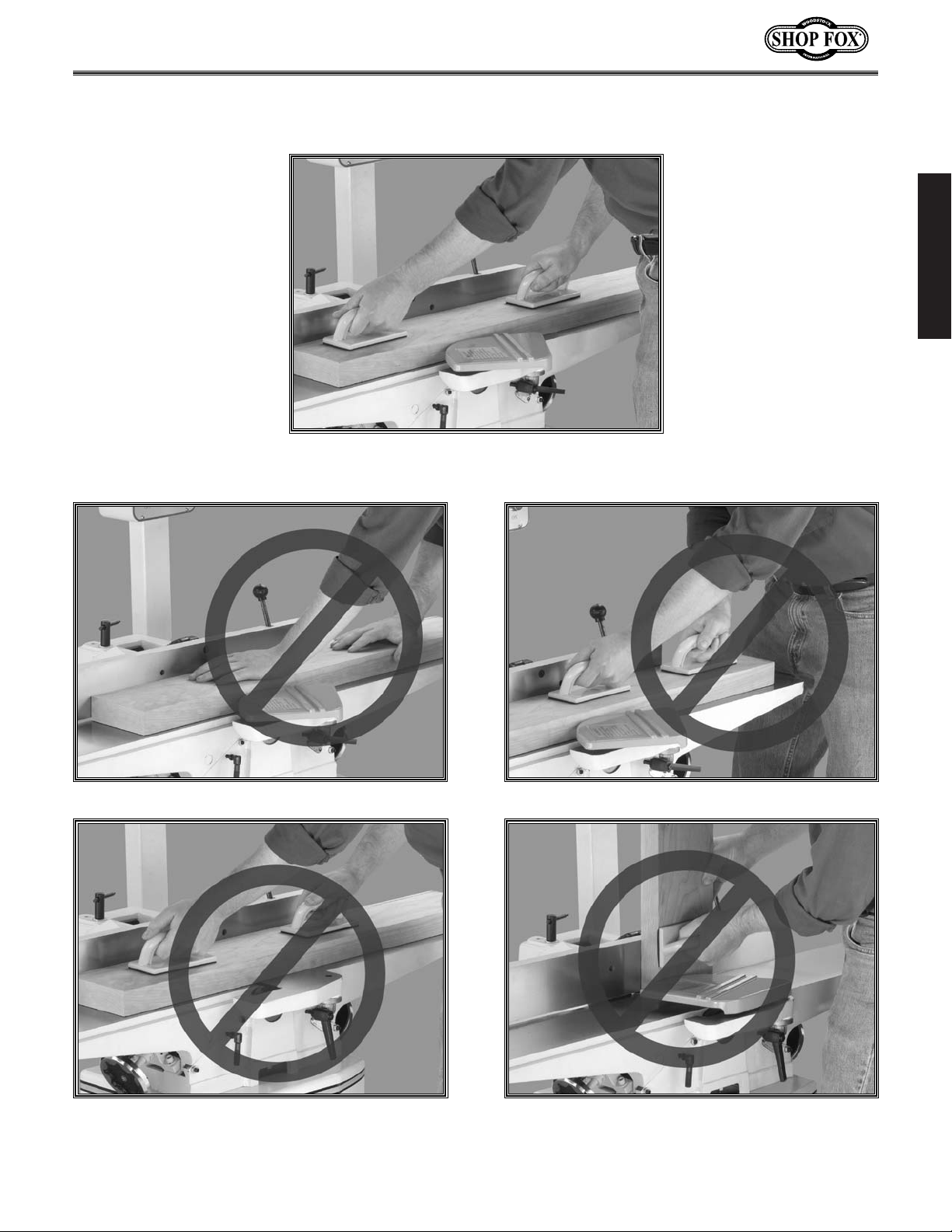
Avoiding Potential Injuries
Figure 1. Correct operator and workpiece position,
guard is in place, and push blocks are being used.
Figure 2. Never surface plane without push blocks!
Figure 4. Never plane/edge-joint with
the guard removed!
Figure 5. Never joint end grain!
Figure 3. Never stand directly behind the workpiece!
Page 10
SAFETY
-8-
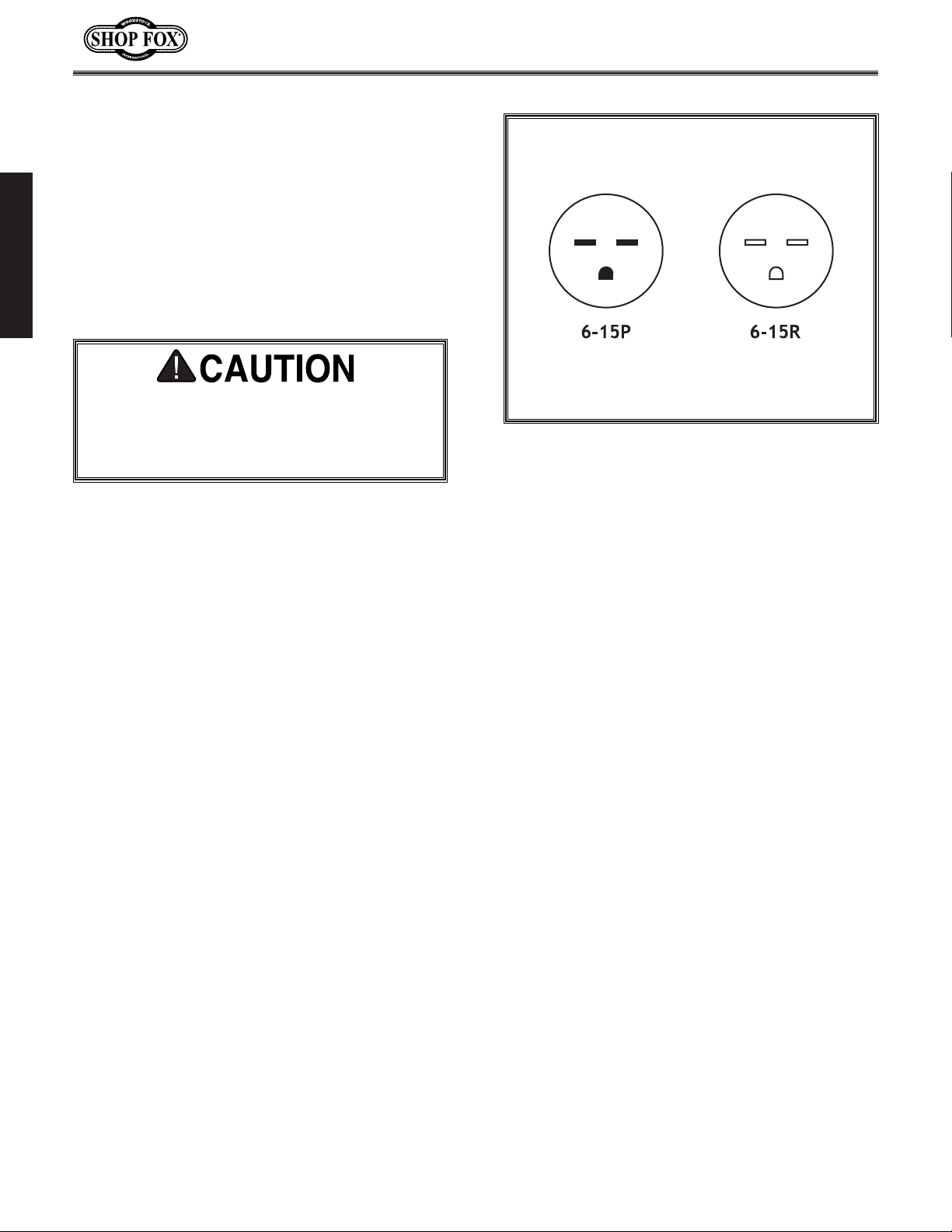
220V Operation
The SHOP FOX®W1684 must be operated at 220
volts. The motor supplied with your new
machine is rated at 2 HP and will draw approximately 14 amps during single-phase, 220 volt
operation. When choosing a circuit for this
machine, consider using one with a 15 amp circuit breaker or fuse.
Figure 8. NEMA-style 6-15 plug and outlet.
Never replace the circuit breaker with one
rated at a higher amperage or damage to
the circuit may occur, and a fire may
result!
When choosing plug and outlet, use a NEMAstyle 6-15 as shown in Figure 8. Keep in mind
that a circuit being used by other machines or
tools at the same time will add to the total load
being applied to the circuit. Add up the load ratings of all machines on the circuit. If this number exceeds the rating of the circuit breaker or
fuse, use a different circuit.
Page 11

SAFETY
-9-
We do not recommend using an extension cord
for 220V equipment. Instead, arrange the
placement of your machinery and installed
wiring to eliminate the need for extension
cords. If you must use an extension cord:
• Make sure it is rated Hard Service (grade S)
or better.
• The extension cord must always contain a
ground wire and plug pin.
• Always repair or replace extension cords
when they become worn or damaged.
• Use at least a 14 gauge cord (preferably 12
gauge).
• DO NOT use a cord over 25 feet long.
Extension Cords Grounding
This machine must be grounded! The electrical
cord supplied with the Model W1684 is not
equipped with a 220 volt plug. Use a plug with a
ground pin. If your outlet does not accommodate a ground pin, have the outlet replaced by a
qualified electrician or have an appropriate
adapter installed and grounded properly. An
adapter with a grounding wire does not guarantee the machine will be grounded. A ground
source must be verified.
Do not remove the grounding pin from any plug and
always make sure all wiring
to the machine is grounded
before operating. Any electrical outlet and circuit that
you plug your machine into
must be grounded. Serious
injury may occur if this
warning is ignored!
Page 12
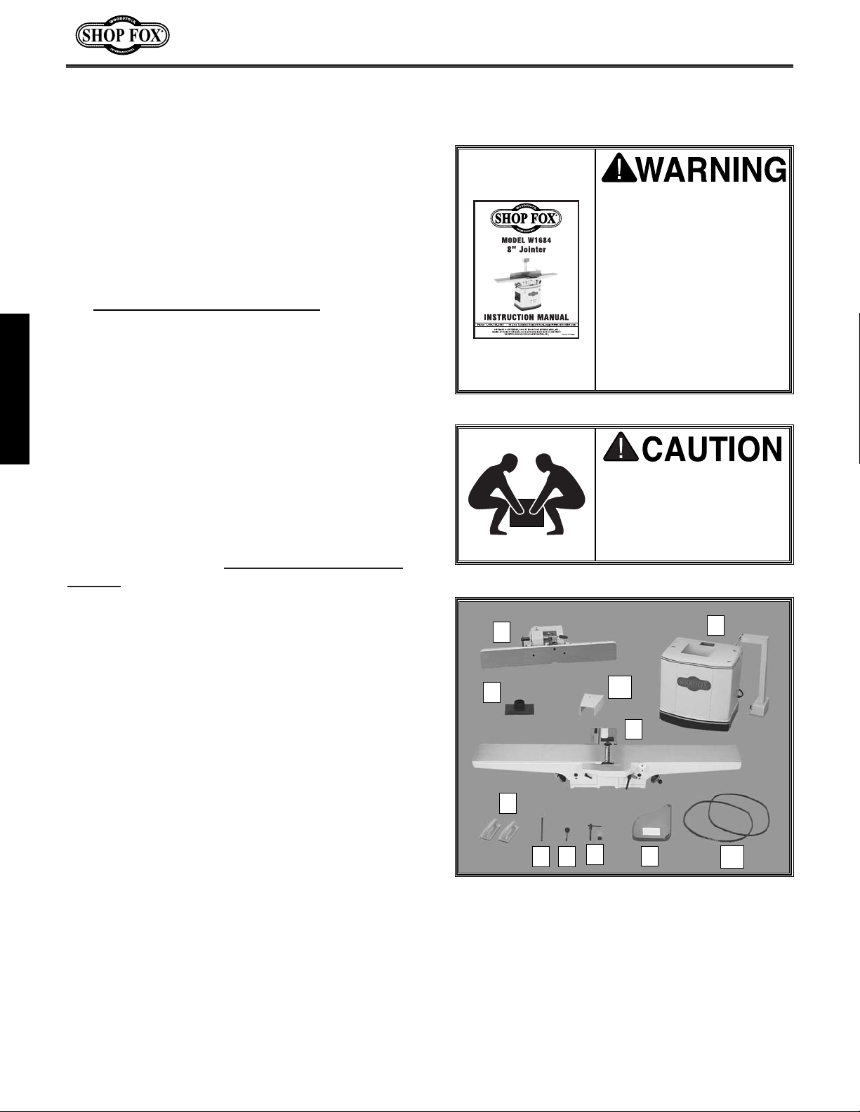
The following is a description of the components
shipped with the SHOP FOX
®
W1684. We recommend that the components be laid out in a similar fashion to those in Figure 9. This will help
in identification before beginning assembly.
Should any part be missing, examine the packaging carefully. If any key parts are missing, find
the part number in the back of this manual and
call Woodstock International, Inc. at 360-7343482 or e-mail at: tech-support@woodstock
-
int.com.
1. Stand, Motor, and Control Panel 1
2. Jointer Assembly w/Handwheels 1
3. Fence Assembly 1
4. Push Blocks 2
5. Cutterhead Guard 1
6. Fence Support Key 1
7. Dust Port 1
8. Fence Tilt Lever
3
⁄8"-16 x 23⁄4"1
9. Lock Handle
1
⁄
2"-12 X 3
3
⁄
4"1
w/Special Nut
1
⁄2
"-12 1
w/Flat Washer 1⁄2" 1
10. V-Belts 2
11. Belt Cover 1
12. Hardware Bags (not shown):
Hex Bolts
3
⁄
8"-16 x
3
⁄
4"3
Flat Washers
3
⁄8"3
Hex Bolts
5
⁄16"-18 x 21⁄2"1
Hex Bolts
5
⁄
16"-18 x 1" 4
Hex Nuts
5
⁄16"-18 4
Flat Washers
5
⁄16"13
Phillps Head Screws
5
⁄
16"-18 x
1
⁄
2"4
Knife Setting Gauge Kit 1
Open End Wrench 8/10MM 1
Allen Wrench 3MM 1
Item Qty.
Figure 9. Jointer components removed from
the boxes and laid out for identification.
ASSEMBLY
-10-
Unpacking
Box Contents
The Model W1684 has been carefully packaged
for safe transporting. If you notice the machine
has been damaged or is missing any parts,
please contact Woodstock International Service
and Support at 1-360-734-3482 or send e-mail
to: tech-support@woodstockint.com
.
Seek lifting assistance
before beginning assembly. The Model W1684 is
a heavy load at 465
pounds.
ASSEMBLY INSTRUCTIONS
Read and understand this
entire instruction manual
before performing any
operations with your
machine. Otherwise, serious personal injury may
occur if safety and operational information is not
understood and followed.
Do not risk your safety by
not reading!
1
2
3
4
5
7
6 8
9
10
11
Page 13
ASSEMBLY
-11-
Shop Preparation
• Floor Load: Your Model W1684 represents a
large weight load in a small footprint. While
most commercial floors are suitable for this
jointer, some residential floors may require
additional bracing to support both machine
and operator.
• Working Clearances: Consider existing and
anticipated needs, size of material to be
processed through each machine, and space
for auxiliary stands, work tables or other
machinery when establishing a location for
your machine.
• Lighting and Outlets: Lighting should be
bright enough to eliminate shadow and prevent eye strain. Electrical circuits should be
dedicated or large enough to handle amperage requirements. Outlets should be located near each machine so power or extension cords are clear of high-traffic areas.
Observe local electrical codes for proper
installation of new lighting, outlets, or circuits.
Cleaning Machine
The table and other unpainted parts of the
Model W1684 are coated with a waxy grease that
protects them from corrosion during shipment.
For optimum performance from your machine,
make sure you clean all moving parts or sliding
contact surfaces that are coated. Clean this
grease off with a solvent cleaner or citrus-based
degreaser. DO NOT use chlorine-based solvents—
if you happen to splash some onto a painted surface, you will ruin the finish.
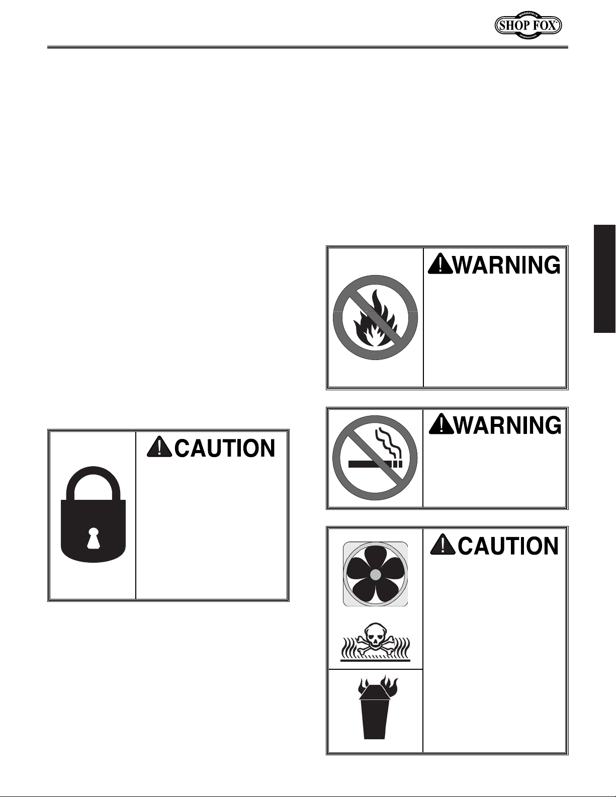
Always make sure that all
entrances to your shop are
locked or that machines
are equipped with safety
lock-out devices to protect
curious children or visitors
from serious injury. Never
allow unsupervised people
in your shop who have not
been fully trained!
Never use flammables
such as gas or other petroleum-based solvents to
clean your machine.
These products have low
flash points and present
the risk of explosion and
severe personal injury!
Never smoke while using
any cleaning solvents.
Smoking may cause explosion or risk of fire when
exposed to these products!
Most solvents used to
clean machinery are
toxic when inhaled or
ingested. Always work in
a well ventilated area
when using these products and keep away from
any potential ignition
sources (pilot lights).
Always dispose of any
waste rags in a ANSI
approved container to
make sure they do not
cause fire hazards.
Page 14

Figure 11. Motor mount bolts (stand tipped
upside down for clarity).
Installing V-Belt
ASSEMBLY
-12-
Beginning
Although the main components of the SHOP
FOX
®
W1684 are assembled at the factory, some
assembly is required. The following series of
instructions are the recommended sequence
best suited for final assembly.
Mounting Jointer
1. Determine the best place for the jointer in
your shop. Get assistance lifting the cabinet
stand and place it in your desired location.
2. With the help of a friend, lift the jointer
assembly onto the stand so the cutterhead
pulley is positioned directly over the slot in
the top of the stand.
3. Align the mounting holes (shown in Figure
10) on the stand to the jointer assembly,
and secure the jointer assembly with the (3)
3
⁄8"-16 x 3⁄4" hex bolts and lock washers from
the hardware bag.
Figure 10. Secure table to stand at these locations.
Make sure that your
machine is unplugged
during all assembly procedures! If this warning
is ignored, serious personal injury may occur.
1. Figure 11 shows the jointer motor mount
bolts (accessible inside stand—picture shows
stand tipped upside down only for clarity).
Loosen the nuts so you can slide the motor
up and install the V-belt.
2. With the V-belt in the grooves of both the
motor pulley and the cutterhead pulley,
pull the motor down tightly by hand and
tighten one corner bolt.
DO NOT over-tighten the belt! Do not use
pry bars or any other device to force the
motor down as this may over-tighten the
belt, which may damage the balance of the
motor shaft or bearings and increase the
wear of the power transfer components.
Page 15

ASSEMBLY
-13-
Figure 12. Pulley and V-belt alignment.
Figure 13. Dust port mounting holes.
3. Place your straightedge against the face of
both pulleys, and swivel the motor as necessary until both pulleys line up with each
other. Tighten the other three motor mount
bolts.
4. Halfway between the two pulleys, lightly
squeeze each side of the belt together to
check the tension.
Belt too loose? If each side of the belt
squeezes toward each other more than
1
⁄2",
increase the tension by repeating steps 2
and 3.
5. Check the V-belt pulley alignment. Minor
adjustments may be made by loosening the
pulley setscrew and sliding the pulley along
the shaft. See Figure 12 for details.
Dust Port
Using the (4) phillips head screws from the hardware bag, attach the dust port over the dust
chute at the mounting holes shown in Figure 13.
Installing Fence
3. Locate the threaded hole on the back of the
infeed side of the fence and install the
fence tilt lever into the fence.
Figure 14. Installing key into fence support.
1. The fence support key has a roll pin fitted in
the center. Install the key into the fence
support keyway and fit the roll pin into the
provided hole. Figure 14 shows the key
installed correctly.
2. Get a friend to help you lift and place the
fence on this support.
DO NOT slide the fence across the outfeed
table. Scratching will result.
NOTICE
Key
Fence
Support
Page 16

ASSEMBLY
-14-
Cutterhead Guard
1. Remove the setscrew from the slot in the
end of the cutterhead guard shaft.
2. Rotate the spring housing clockwise (looking
at the face of the knob) 1 full turn and
insert the cutterhead shaft into the pivot
hole as shown in Figure 16.
3. Fit the shaft slot over the flat metal piece
inside the spring housing. The shaft should
drop through the bottom of the housing.
4. When installed, the cutterhead guard
should press firmly against the fence and
should be completely covering the cutterhead as shown in Figure 17.
5. Move the cutterhead guard back and forth
to make sure that it automatically returns
back to its proper position against the fence
and over the cutterhead.
6. Make sure the cutterhead guard has the
correct return pressure. If the pressure is
weak or there is no return pressure at all,
remove the shaft, tighten the spring housing
by rotating clockwise, and re-install the
shaft to check for proper operation.
7. Replace the setscrew at the end of the
shaft, so that the cutterhead guard cannot
be removed from the pivot hole.
Figure 17. Guard in proper position against
the fence and completely over the cutterhead.
Figure 16. Rotate spring housing clockwise 1 full
turn and insert cutterhead guard shaft.
Figure 15. Installing lock handle and special nut.
4. Place the 1⁄2" flat washer over the lock han-
dle and install the special nut from underneath the fence support as shown in Figure
15.
5. Make sure the splines on the special nut pro-
trude into the adjustment slot, then insert
the handle shaft through the fence housing
and thread it into the special nut.
Special
Nut
Lock
Handle
Tilt
Lever
Cutterhead
Guard
Shaft
Spring
Housing
Pivot
Hole
Page 17

ASSEMBLY
-15-
Figure 18. Attach belt guard to stand
with the hex bolt.
Belt Guard
Attach the belt cover to the cabinet stand with
the
5
⁄16"-18 x 21⁄2" hex bolt and 5⁄16" flat washer
as shown in Figure 18.
Knife Gauge
The knife gauge consists of a steel rod, two
adjuster arms and two E-clips.
To assemble the knife gauge:
1. Insert the steel rod through each adjuster
arm.
2. Snap the E-clips into the grooves at the ends
of the steel rod so your assembly looks like
the knife gauge shown in Figure 19. See
page 16-17 for usage instructions.
Control Pedestal
1. Mount the control pedestal to the back of
the cabinet stand as shown in Figure 20.
2. Secure the control pedestal with the (4)
5
⁄16"-18 x 1" hex bolts, (4) 5⁄16"-18 hex nuts
and (8)
5
⁄16" washers from the hardware
bag.
Figure 19. Knife setting gauge.
Figure 20. Mounting pedestal switch to stand.
Make sure that your
machine is unplugged
during all assembly procedures! If this warning
is ignored, serious personal injury may occur.
Page 18

ADJUSTMENTS
-16-
ADJUSTMENTS
Checking Knives
The cutterhead knives have been set at the factory and should require no adjustments when
you first receive your jointer. However, it is
always a good idea to verify the accuracy of any
adjustments that will affect your finished product.
As your jointer gets used, the knives will need to
be routinely inspected, adjusted, and ultimately sharpened or replaced.
To inspect the knife position in the cutterhead:
1. Unplug the jointer!
2. Remove the cutterhead guard from the
table, so that you have clear access to the
top of the cutterhead.
3. Remove the pulley cover at the back of the
machine and slowly turn the cutterhead
with the pulley until one of the knives is
exposed and is easily accessible.
4. Place the knife setting gauge on the cutterhead as shown in Figure 21 to check the
height of each knife. Both gauge feet should
sit solidly on the cutterhead and the contact
point in the center of the gauge arm should
barely touch the tip of the knife.
If the gauge fits on the cutterhead as
described above, then the knife height is correct. Move on to the next knife and check in the
same manner. If all of the other knives are at
the correct height, then no adjustments are
necessary.
If either gauge arm does not fit on the cutterhead as described above, or if the center contact point does not touch the knife, then the
knife position needs to be adjusted. Refer to
the “Adjusting Knives” instructions in this section and adjust the knives.
Figure 21. Place the knife setting gauge on the
cutterhead as shown to inspect accuracy of
knife position in cutterhead.
Make sure that your
machine is unplugged
during any adjustment
procedures! If this
warning is ignored, serious personal injury may
occur.
The cutting edges on this
equipment are extremely sharp and could cause
deep cuts! Be very careful when working around
these edges. Never directly grab the cutterhead to move it!
These Points Must
All Touch Evenly
Page 19

ADJUSTMENTS
-17-
Adjusting Knives
The knives in the Model W1684 come from the
factory with jack screws installed. Springs are
also included as an option for knife adjustments,
depending on your preference. Figure 22 shows
an illustration of the cutterhead components.
To adjust the knives:
1. Unplug the jointer!
2. Remove the cutterhead guard from the
table, so that you have clear access to the
top of the cutterhead.
3. Remove the pulley cover at the back of the
machine and slowly turn the cutterhead
with the pulley until one of the knives is
exposed and is easily accessible.
4. Loosen the cutterhead gib bolts so that the
knife is loose. The first time you set your
knives, remove either the jack screws or
springs, depending on which option you do
not want to use.
5. Place the knife gauge on the cutterhead as
described in the “Checking Knives” instructions and as shown in Figure 22.
6. Jack Screws—Adjust the jack screws with
an Allen wrench until the knife edge barely
touches the contact point on the knife setting jig. Snug the gib bolts but do not fully
tighten them. Repeat this step with each
jack screw on each knife.
Springs—The springs will push the knife
against the setting jig (.070" above cutterhead body). Keep downward pressure on the
jig until you tighten the gib bolts. Repeat
this step with the other knives, then snug
the gib bolts without fully tightening them.
7. Start at the beginning knife and slightly
tighten each gib bolt on each knife in the
sequence shown in Figure 23. Repeat this
step two or three times until all gib bolts
are completely tight. All knives should be
set within .002" from one end to the other
and within .002" from one knife to another.
Figure 22.
Understanding cutterhead assembly.
Figure 23.
Gib bolt tightening sequence.
NOTICE
Uneven tightening of the gib bolts may cause
the cutterhead to become unbalanced,
which will lead to premature wear and tear
of the knives and produce poor results!
Wear heavy leather gloves when loosening/tightening gib bolts in case the wrench
slips and your hand hits the knife. Jointer
knives are dangerously sharp. If care is not
taken, serious injury may occur.
Page 20

Figure 24. These are the table gib controls.
Table Gibs
The table gibs allow you to control how easy the
table moves up or down and control the precision of the table movement along the dovetail
ways. Since the table gibs are factory set, they
do not need to be adjusted unless the table is
too loose or too tight when moving along the
dovetail ways. (Always make sure the table lock
is released before determining whether the
table travel is too loose or too tight.)
To adjust the table gibs:
1. Unplug the jointer!
2. Locate the setscrews and jam nuts shown in
Figure 24. These are used to tighten/loosen
the table gibs.
3. Use the trial-and-error method by adjusting
the setscrews and moving the table to
achieve the correct table movement. When
both tables move smooth and responsive,
with no indication of side-to-side movement, then the table gibs are set right.
ADJUSTMENTS
-18-
Figure 25. This is the outfeed table lock handle.
Adjusting Tables
Figure 26. Top dead center.
The tables are adjusted by rotating the handwheels. In order to accurately joint or plane a
piece of stock, both tables must be properly
adjusted, starting with the outfeed table.
To adjust the outfeed table:
1. Unplug the jointer!
2. Make sure that the knives have been prop-
erly adjusted before continuing.
3. Turn the lock handle counterclockwise to
loosen the lock, so that the outfeed table
can move freely. Figure 25 shows the outfeed table lock handle.
4. Remove the motor pulley cover to expose
the V-belts and pulleys. Rotate the cutterhead by turning the cutterhead pulley until
one of the blades is at the highest point in
its arc (top dead center) as illustrated in
Figure 26.
Page 21

ADJUSTMENTS
-19-
Figure 29. Pointer set to “0”.
Figure 28. Infeed table even with outfeed.
Scale can now be set to “0”.
Figure 27. Straightedge centered on outfeed
table and even with knife at top dead center.
5. Place a good quality straightedge across the
length of the outfeed table and just over
the cutterhead as shown in Figure 27. (This
adjustment works best if the straightedge is
placed in the center of the outfeed table.)
6. Using the handwheel under the outfeed
table, raise or lower the outfeed table until
the straightedge barely touches the edge of
the knife.
7. Rotate the cutterhead back and forth to
verify that it is still positioned at top dead
center.
8. Tighten the table lock handle and double
check your adjustment for accuracy.
After adjusting the outfeed table and ensuring
its accuracy, it can be left alone until the next
time you adjust the knives or if you notice that
it might have moved. The infeed table, on the
other hand, will regularly be adjusted to set the
cutting depth. When the jointer is new, the
pointer on the depth scale must be calibrated to
ensure that the infeed table movement is accurate if read from the scale.
To calibrate the pointer on the depth scale:
1. Loosen the infeed table lock handle.
2. Place a good quality straightedge in the
center and along the length of the outfeed
table.
3. Slide the straightedge over the infeed table.
4. Raise the infeed table so that it barely
touches the bottom of the straightedge as
shown in Figure 28.
5. Secure the infeed table with the lock handle
and set the pointer on the depth scale to
“0” as shown in Figure 29. You can now use
the scale to adjust your depth of cut when
it is time to operate the jointer.
Page 22

ADJUSTMENTS
-20-
Figure 30. Fence stops and fence-tilt lock handle.
Figure 31. Squaring fence with a try square.
Figure 32. This is the fence in the 45˚ R position.
Fence Stops
Stop bolts on the back of the fence (shown in
Figure 30) allow you to quickly and accurately
move the fence to 90˚, 45˚ R (to the right) and
45˚ L (to the left). The position of these stops
must be checked and possibly adjusted before
they are used for the first time.
The fence stops are simple hex bolts (a nut for
45˚ L) that thread in or out to match the depth
required. Each fence stop has a jam nut to lock
the stops in place for repeatable accuracy.
To check/adjust the fence stops:
1. Unplug the jointer!
2. 90˚ Stop — Loosen the fence-tilt lock han-
dle. Move the fence into an upright position
so the 90˚ stop is resting against the metal
tab. Place a try square on the table and
against the fence as shown in Figure 31. If
the square does not line up with the table
and fence evenly, adjust the 90˚ stop bolt
until it does. Tighten the jam nut down to
prevent it from moving and retighten the
fence-tilt lock handle.
3. 45˚ R Stop — Make sure the fence-tilt lock
handle is loose, then slide the 90˚ stop tab
out of the way and tilt the fence back into
position shown in Figure 32. The fence
should rest on the stop. Check the angle
with a 45˚ angle gauge to verify for accuracy. Adjust the stop if needed and tighten
the jam nut. Retighten the fence-tilt lock
handle before operation.
4. 45˚ L Stop — Loosen the fence-tilt lock handle. Move the fence 45˚ to the left so it tilts
toward the table and stops on the 45˚L stop
nut. Adjust the stop nut if necessary and
tighten the jam nut (the second nut behind
the first) to the stop nut to keep it from
moving. Retighten the fence-tilt lock handle
before operation.
Always double check the stop bolt position
after tightening the jam nuts!
45˚L
Fence-Tilt
Lock Handle
45˚R
90˚
Page 23

OPERATIONS
-21-
OPERATIONS
Starting Jointer
Basic Operations
Once assembly is complete and adjustments
have been made, the jointer is ready for a test
run. The purpose of a test run is to identify any
unusual noises and vibrations, as well as to confirm the machine is performing as intended.
1. With your finger poised to hit the STOP but-
ton if there is a problem, turn on the jointer by pressing the START button on the
power switch.
2. Once the jointer is running, listen for any
unusual noises. It should run smoothly with
little or no vibrations. If there are any
unusual noises or vibrations, shut the jointer off immediately. It should not be run any
further until the problems are corrected.
3. Unplug the jointer and investigate the
source of the noise or vibration. DO NOT
make any adjustments to the machine while
it is plugged in.
4. Repeat Steps 1-4 until the jointer runs
smoothly.
Always wear safety glasses during operations.
Serious injury may occur
if this is warning is ignored!
Always keep loose
clothing and long hair
secured and away from
moving parts.
All operations on the jointer are made by placing the workpiece firmly against the infeed table
and the fence, and then passing the workpiece
completely over the cutterhead.
Operational tips as well as specific types of cuts
are mentioned further on in this section. If you
are a beginner, practice each new type of cut
with the fence in the desired position, with the
tables set even, and the machine turned OFF.
Get a feel for board control and hand position,
and practice feeding the board across the table
while maintaining absolute control. When you
are ready for the actual cut, keep in mind that
shallow cutting depths allow you to have more
control.
Always wear a dust mask
and safety glasses in addition to using a dust collector. This machine produces sawdust that may
cause allergic reactions
or respiratory problems.
DO NOT operate this machine without an adequate dust collection
system. This machine
creates substantial
amounts of wood dust
while in operation.
Failure to use a dust collection system can result
in short and long-term
respiratory illness.
Page 24

OPERATIONS
-22-
Operation Requirements
• Never allow hands or push blocks to come
within 4" of the cutterhead while it is moving.
• Carefully inspect any lumber that you plan
to run through the jointer. Some defects
such as moderate twisting, loose knots or
severe cracks may make the stock unusable.
• Only use clean stock. See Figure 33.
Remove all dirt, nails, staples, imbedded
gravel, etc. from any lumber you plan on
using. A hidden nail in a workpiece will
instantly damage the sharp edges of the
knives. This will cause unsatisfactory results
in future operations.
• Use ONLY natural wood fiber. Never use
wood composites such as particle board,
plywood or MDF. Also, never use laminates,
formica or other synthetic materials.
• Always cut WITH the grain. Cutting against
the pattern of the growth rings will chip the
wood instead of cutting it. This will make
the workpiece look rough and irregular and
may increase the chances of a kickback.
To determine if you are going to be cutting
with the grain, look at the pattern on the
side of the board. If the arc of the cutterhead knife will follow the same lines in the
grain pattern, then you will be cutting WITH
the grain. If the arc of the cutterhead knife
will cross the lines in the grain pattern,
then you will be cutting AGAINST the grain.
Refer to Figure 34 for clarification.
• Avoid using wood with a high moisture content. Stock with more than 20% moisture, or
stock that has been exposed to rain or snow,
will cut poorly and cause unnecessary wear
on the knives and motor. Excess moisture
may also cause rust or corrosion problems.
• Never take cuts deeper than
1
⁄8" and plan on
taking multiple cuts before you can achieve
a completely flat surface.
Figure 33. Only plane clean stock.
Figure 34.
Correct and incorrect grain
alignment to cutterhead.
• Sharpen knives immediately if they show
any signs of dulling during operation. We
recommend keeping a spare set of knives at
all times.
• Keep your work area clear. Always make
sure that long workpieces are supported and
have enough room to exit the jointer.
Page 25

OPERATIONS
-23-
Surface Planing
One of the most common operations on the jointer is surface planing. Surface planing produces
one flat surface on a piece of stock as shown in
Figure 35.
After being surface planed, the stock is usually
run through a thickness planer so the board
thickness is consistent from one end to the
other.
Figure 36 shows an example of an operator
using the jointer to surface plane a piece of
wood stock. Notice that the operator’s body is
not directly behind the stock and that the operator is using push blocks to feed the board.
To perform a surface planing operation:
1. Make sure you have read and are familiar
with Section 1: Safety and the “Operation
Musts” in this section.
2. Place the workpiece so the concave side is
down on the infeed table and press the
workpiece firmly against the fence.
3. Start the jointer.
4. Using push blocks with both hands and keep-
ing firm (not hard) pressure on the fence
and table, feed the workpiece into the cutterhead.
5. As your leading hand gets within 4" of the
cutterhead, lift the push block up and over
the cutterhead and place it on the workpiece as it passes over the outfeed table. Do
the same thing when your trailing hand
nears the cutterhead and try to maintain
pressure on the outfeed table. Never let
your hands get closer than 4" from the cutterhead!
6. Repeat steps 4-5 until the surface is flat.
Figure 35. Surface planing produces a flat sur-
face from concave stock.
Portion
Removed With
Jointer
Always wear safety
glasses to prevent serious personal injury!
Figure 36. This is an example of a surface
planing operation.
Page 26

OPERATIONS
-24-
Edge Jointing
Edge jointing is passing the workpiece over the
jointer on its edge as shown in Figure 37. This
process makes the edges of a workpiece perfectly flat.
Stock must be edge jointed on the concave side.
The convex side should then be cut straight with
a table saw. This process is commonly used to
prepare the workpiece to be glued-up as part of
a larger assembly or to simply salvage warped
stock.
Figure 38 shows an example of an operator edge
jointing. Notice that the operator’s body is not
directly in line with the stock and that he maintains a stable hand position while keeping the
board firmly on the table and against the fence.
To perform an edge jointing operation:
1. Follow Section 1: Safety and the “Operation
Musts” in this section.
2. Place the workpiece so the concave edge is
down on the infeed table and press the
workpiece firmly against the fence.
3. Start the jointer.
4. Using a tight grip with your hands in a sta-
ble position and keeping the workpiece
firmly against the table and fence, feed the
workpiece into the cutterhead.
5. If your leading hand gets within 4" of the
cutterhead, lift it up and over the cutterhead and place it on the workpiece as it
passes over the outfeed table. Do the same
thing when your trailing hand nears the cutterhead and try to maintain pressure on the
outfeed table. Never let your hands get
closer than 4" from the cutterhead!
6. Repeat steps 4-5 until the surface is flat.
Figure 37. Edge jointing produces one flat edge.
Portion
Removed With
Jointer
Always wear safety
glasses to prevent serious personal injury!
Figure 38. This is an example of an edge
jointing operation.
Page 27

OPERATIONS
-25-
Bevel Cutting
Bevel cutting is very similar to edge jointing, but
done with the fence tilted to a specific angle in
order to produce an angled edge as shown in
Figure 39. Usually bevel cuts are made on two
boards that will be joined together at a corner.
For bevel cuts, the Model W1684 has preset
stops at 45˚ L and 45˚ R. If a different angle is
desired, use a bevel gauge to set the fence,
then lock it in position.
Figure 40 shows an example of an operator
bevel cutting at 45˚ R. Notice that the operator’s body is not directly in line with the stock
and that he maintains a stable hand position
while keeping the board firmly on the table and
against the fence.
To perform a bevel cutting operation:
1. Follow Section 1: Safety and the “Operation
Requirements” in this section.
2. Set the fence to the desired angle. Place
the workpiece down on the infeed table and
press it firmly against the fence.
3. Start the jointer.
4. Keep the workpiece firmly against the table
and fence, and feed the workpiece into the
cutterhead.
5. As your leading hand gets within 4" of the
cutterhead, lift the push block up and over
the cutterhead and place it on the workpiece as it passes over the outfeed table. Do
the same thing when your trailing hand
nears the cutterhead and try to maintain
pressure on the outfeed table. Never let
your hands get closer than 4" from the cutterhead and always make sure that you have
control over the workpiece.
6. Repeat steps 4-5 until the surface is flat.
Figure 39. Bevel cutting produces an
angled edge.
Portion
Removed With
Jointer
Figure 40. This is an example of a bevel cut-
ting operation with the fence set at 45˚.
Always wear safety
glasses to prevent serious personal injury!
Page 28

OPERATIONS
-26-
Rabbet Cutting
Rabbet cutting recesses a section of a workpiece
edge to create a strong but simple joint. Figure
41 illustrates a basic rabbet cut and two common joints.
Figure 42 shows an operator performing a rabbet cut. Notice that the fence is positioned close
to the edge of the table. The operator’s body is
not directly in line with the stock and he maintains a stable hand position while keeping the
board firmly on the table and against the fence.
To perform a rabbet cutting operation:
1. Follow Section 1: Safety and the “Operation
Musts” in this section.
2. Determine the width of your desired rabbet
and set the fence that distance away from
the edge of the knives.
3. Place the workpiece down on the infeed
table and press it firmly against the fence.
4. Start the jointer.
5. Keep the workpiece firmly against the table
and fence, and feed the workpiece into the
cutterhead.
6. As your leading hand gets within 4" of the
cutterhead, lift it up and over the cutterhead and place it on the workpiece as it
passes over the outfeed table. Do the same
thing when your trailing hand nears the cutterhead. Never let your hands get closer
than 4" away from the cutterhead!
7. Repeat steps 4-6 until you have achieved
your desired rabbeting depth. The maximum rabbet depth for the Model W1684 is
1
⁄2".
Figure 41.
Figure 42. This is an example of a rabbet
cutting operation.
Rabbet Joints
Rabbet Cut
Always wear safety
glasses to prevent serious personal injury!
Page 29

MAINTENANCE
-27-
MAINTENANCE
Regular periodic maintenance on your Model
W1684 will ensure its optimum performance.
Make a habit of inspecting your machine each
time you use it. Check for the following conditions and repair or replace when necessary.
1. Loose mounting bolts.
2. Worn switch.
3. Worn or damaged cords and plugs.
4. Damaged drive belt.
5. Any other condition that could hamper the
safe operation of this machine.
6. Dull or loose knives.
General
Make sure that your machine is unplugged during all maintenance procedures! If this warning
is ignored, serious personal injury may occur.
Always wear safety
glasses to prevent serious personal injury!
Always keep loose
clothing and long hair
secured and away from
moving parts.
Table Surface
Tables can be kept rust-free with regular applications of products like SLIPIT
®
as shown in
Figure 43. For long term storage you may want
to consider products like Boeshield T-9™.
Whichever product you ultimately choose for a
table lubricant, make sure that it protects
against rust, allows the stock to slide easily and
will not stain expensive stock.
Figure 43. Applying lubricant to table surface.
Page 30

MAINTENANCE
-28-
Lubrication
Since all bearings are sealed and permanently
lubricated, simply leave them alone until they
need to be replaced. Do not lubricate them.
For the moving mechanisms on the fence assembly, an occasional application of light machine
oil is all that is necessary. Before applying lubricant, wipe the fence clean. Lubricate the pivot
points and move the fence back and forth as
shown in Figure 44. Your goal is to achieve adequate lubrication. Too much lubrication will
attract dirt and sawdust.
Finally keep the sliding surfaces clean and free
of any dirt or sawdust. Give these areas, especially the key and keyway, an application of
white lithium grease as shown in Figure 45. Dry
graphite is also a great alternative to grease for
these areas because it does not attract dirt or
sawdust.
Figure 44. Lubricating fence pivot points.
Figure 45. Greasing fence keyway.
Figure 46. Motor mount bolts (stand tipped
upsidedown for clarity).
Sharpening Knives
Unless you are well experienced with knife
sharpening, have your knives sharpened by a
professional or simply replace them.
Replacing V-Belt
If the V-belt becomes worn, cracked or glazed,
replace it.
To replace the V-belt:
1. Unplug the jointer!
2. Open the access door and loosen the motor
mount bolts shown in Figure 46 to loosen
the V-belt.
3. Remove the V-belt from the pulleys.
4. Follow the “Installing V-Belt” instructions
on page 12 to install the V-belt.
Page 31

MAINTENANCE
-29-
Troubleshooting
SYMPTOM
Motor will not start and fuses or
breakers blow.
Motor will not start.
Motor overheats.
Motor stalls, resulting in blown
fuses or tripped breaker.
Loud, repetitious noise coming
from jointer.
Jointer slows when operating.
Jointer cuts loud, overheats or
bogs down in cut.
Gouge in the end of board that is
uneven with rest of cut (snipe).
Workpiece stops or bumps outfeed table in middle of cut.
POSSIBLE REASON
1. Short circuit in line cord or plug.
2. Short circuit in motor or loose connections.
3. Incorrect fuses or circuit breakers in
power line.
1. Voltage too low.
2. Open circuit in motor or loose connections.
1. Motor overloaded.
2. Restricted air circulation through
motor.
1. Short circuit in motor or loose connections.
2. Voltage too low.
3. Incorrect fuses or circuit breakers in
power line.
4. Motor overloaded.
1. Pulley setscrews or keys are missing
or loose.
2. Motor fan is hitting the cover.
3. V-belt is defective.
1. Too fast of a feed rate.
2. Too deep of cut.
1. Too deep of cut.
2. Knives are dull.
1. Outfeed table set too low.
1. Outfeed table set too high.
HOW TO REMEDY
1. Inspect cord or plug for damaged insulation and shorted
wires.
2. Inspect all connections on motor for loose or shorted terminals or worn insulation.
3. Replace with correct fuses or circuit breakers.
1. Call an electrician to correct power line voltage.
2. Inspect all lead connections on motor for loose or open
connections.
1. Reduce load on motor.
2. Clean out motor to provide proper circulation.
1. Inspect connections on motor for loose or shorted terminals or worn insulation.
2. Call an electrician to correct power line voltage.
3. Replace with correct fuses or circuit breakers.
4. Reduce load placed on motor.
1. Replace or tighten setscrews or keys if necessary.
2. Tighten fan or shim motor cover.
3. Replace V-belt. See page 28.
1. Feed workpiece at a slower rate.
2. Decrease depth of cut.
1. Decrease depth of cut.
2. Replace or sharpen knives.
1. Set outfeed table even with cutterhead knife at top dead
center. See page 18-19.
1. Set outfeed table even with cutterhead knife at top dead
center. See page 18-19.
Page 32

MAINTENANCE
-30-
Troubleshooting
SYMPTOM
Chipping occurs on workpiece.
Grain is fuzzy after jointing.
Lines or ridges in board.
Uneven knife marks on board.
Wavy surface or chatter marks on
board.
Edge is concave or convex after
edge jointing.
Workpiece tapered after jointing.
POSSIBLE REASON
1. Grain direction incorrect or knots in
workpiece.
2. Dull knives.
3. Too fast of a feed rate.
4. Too deep of cut.
1. Wood may have high moisture content. Check with moisture meter.
2. Dull knives.
3. Wood is figured or is a species that
has naturally fuzzy characteristics.
1. Nicked or chipped knives.
1. One or more knives out of adjustment.
1. Too fast of a feed rate.
2. One or more knives out of adjustment.
1. Workpiece not held with even pressure on infeed and outfeed table.
2. Workpiece began too uneven.
3. Workpiece has excessive bow or
twist along its length.
4. Insufficient number of passes.
5. Outfeed table not properly aligned
with cutterhead.
1. Outfeed table set too low.
HOW TO REMEDY
1. Feed workpiece with the grain. Inspect stock for knots or
try again with different stock.
2. Replace or sharpen knives.
3. Feed the workpiece at a slower rate.
4. Decrease depth of cut.
1. Allow wood to dry.
2. Replace or sharpen knives.
3. Use different wood or plan on extra sanding.
1. Inspect and replace or sharpen knives.
1. Reset/adjust knives in cutterhead. See page 17.
1. Feed the workpiece at a slower rate.
2. Reset/adjust knives in cutterhead. See page 17.
1. Hold workpiece with even pressure as it moves through
the cutterhead. See “Edge Jointing” on page 24.
2. Take partial cuts to remove extreme high spots before
doing a full pass.
3. Surface plane one face so there is a good surface to position against the fence.
4. Three to five passes may be needed to achieve a perfect
edge, depending on starting condition and depth of cut.
5. Set outfeed table even with cutterhead knife at top dead
center. See page 18-19.
1. Set outfeed table even with cutterhead knife at top dead
center. See page 18-19.
Outfeed table set too low. Outfeed table set too high.
Outfeed
Table
Feed Direction
Infeed
Table
Cutterhead Rotation
Page 33

MAINTENANCE
W1684 WIRING DIAGRAM
SINGLE-PHASE
220V POWER SOURCE
A
L1/1 L3/5 7L2/3
T1/2 T3/6 8
U/2
T2/4
V/4
W/6
96 98
95
MOTOR
13
AMP
B
RESET
16
19
Page 34

PARTS
-32-
The following pages contain parts diagrams/lists
and a warranty card for your SHOP FOX
®
Model
W1684.
If you need parts or help in assembling your
machine, or if you need operational information, we encourage you to call our Service
Department. Our trained service technicians will
be glad to help you.
If you have comments dealing specifically with
this manual, please write to us using the address
in the General Information. The specifications,
drawings, and photographs illustrated in this
manual represent the Model W1684 as supplied
when the manual was prepared. However, due
to Woodstock International, Inc.’s policy of continuous improvement, changes may be made at
any time with no obligation on the part of
Woodstock International, Inc.
We have included some important safety measures that are essential to this machine’s operation. While most safety measures are generally
universal, we remind you that each workshop is
different and safety rules should be considered
as they apply to your specific situation.
We recommend you keep this manual for complete information regarding Woodstock
International, Inc.’s warranty and return policy.
Should a problem arise, we recommend that you
keep your proof of purchase with your manual.
If you need additional technical information
relating to this machine, or if you need general
assistance or replacement parts, please contact
the Service Department at 1-360-734-3482 or email: tech-support@woodstockint.com
.
Additional information sources are necessary to
realize the full potential of this machine. Trade
journals, woodworking magazines, and your
local library are good places to start.
The Model W1684 is specifically designed for
wood cutting operations. DO NOT MODIFY
AND/OR USE THIS MACHINE FOR ANY OTHER
PURPOSE. MODIFICATIONS OR IMPROPER USE
OF THIS TOOL WILL VOID THE WARRANTY. If
you are confused about any aspect of this
machine, DO NOT use it until all your questions
have been answered.
CLOSURE
Always wear safety glasses or goggles when
operating equipment. Operating this equipment creates the potential for flying debris
to cause eye injury. Everyday glasses or
reading glasses only have impact resistant
lenses, they are not safety glasses. Be certain the safety glasses you wear meet the
appropriate standards of the American
National Standards Institute (ANSI).
Use the tool with respect and caution to
lessen the possibility of mechanical damage
or operator injury. As with all power tools,
there is danger associated with the Model
W1684. If normal safety precautions are
overlooked or ignored, injury to the operator or others in the area is likely.
Page 35

PARTS
-33-
51
45
19
43
17
31
17
44
20
37
9A
6
33
34
9
11
12
2
32
3
22
7
24
41
8
35
36
40
21
48
28
10
28
49
27
14
is below. Failure
to comply will
result in serious
personal injury!
DO NOT remove
this guard! A high
speed cutterhead
push blocks!
18
Always use
1
30
5
29
42
23
39
16
15
49
24
50
41
3
46
27
12
48
4
48
8
11
7
34
9
33
9A
6
47
25
Page 36

PARTS
-34-
105
101
126
104
123
114
119
130
104
126
116
112
106
129
107
127
118
125
121
117
110
122
108
103
109
118
102
120
124
111
115
128
Page 37

PARTS
-35-
REF PART # DESCRIPTION REF PART # DESCRIPTION
1 X1684001 INFEED TABLE
2
XPSS01
SETSCREW
5
/16"-18 x 1"
3 X1684003 TABLE ADJUST ROD
4 X1684004 GIB
5 X1684005 TABLE LOCK HANDLE
6 XPB22 HEX BOLT
5
/16"-18 x 13/4"
7 XPSS11 SETSCREW
1
/4"-20 x 1/4"
8 X1684008 LEAD SCREW BRACKET
9 X1684009 HANDWHEEL
09A X168409A KNOB
10 X1684010 SPRING PIN
11 X1684011 LOCK COLLAR
12 X1684012 LEAD SCREW
13 XPRO1M EXT RETAINING RING 10MM
14 XPSS08 SETSCREW
5
⁄16"-18 x 1⁄2"
15 X1679238 SCALE
16 X1679239 RIVET
17 XPB24 HEX BOLT
3
⁄8"-16 x 11⁄4"
18 X1684018 CUTTERHEAD GUARD
19 X1684019 FENCE SUPPORT KEY
20 XPW02 FLAT WASHER
3
⁄8"
21 X1684021 SPRING
22 XPB17 HEX BOLT
5
⁄
16"-18 x 2
3
⁄
4"
23 X1684023 W1684 SERIAL# LABEL
24 XPW07 FLAT WASHER
5
⁄16"
25 XPS01 PHLP HD SCREW 10-24 x
1
⁄
2"
27 XPW07 FLAT WASHER
5
⁄16"
28 X1684028 EXTENSION BRACKET
29 XPW02 FLAT WASHER
3
⁄
8"
30 X1684030 BASE
31 X1684031 OUTFEED TABLE
32 XPN02 HEX NUT
5
⁄
16"-18
33 X1684033 SPACER
34 XPN02 HEX NUT
5
⁄16"-18
35 X1684035 BELT GUARD
36 XPW07 FLAT WASHER
5
⁄16"
37 X1684037 W1684 CUTTERHEAD LABEL
38 X1684038 STUD
39 X1679244 LOCK HANDLE
5
⁄16"-18 x 11⁄4"
40 X1684040 SPRING PIN
41 XPSB03 CAP SCREW
5
⁄16"-18 x 1"
42 X1679013 POINTER
43 X1684043 FENCE SUPPORT
44 XPW02 FLAT WASHER
3
⁄8"
45 X1684045 SPRING PIN
46 XPS23 PHLP HD SCREW 8-32 x
1
⁄4
"
47 XPW03 FLAT WASHER #10
48 XPW01 FLAT WASHER
1
⁄2"
49 XPB09 HEX BOLT
5
⁄16"-18 x 1⁄2"
50 XPB24 HEX BOLT
3
⁄8"-16 x 11⁄4"
51 W1400 PUSH BLOCK
101 X1684101 FENCE
102 X1679102 SPECIAL SCREW
3
⁄8"-16 X 11⁄2"
103 X1684103 FENCE HINGE
104 X1679101 PIVOT STUD
1
⁄2"-20 X 3⁄4"
105 X1679104 SPECIAL SCREW
5
⁄16"-18 X 13⁄4"
106 X1684106 TILT LEVER
107 X1684107 KNOB
3
⁄
8"
108 XPN19 HEX NUT
7
⁄16"-14
109 X1684109 FENCE BRACKET
110 X1684110 FENCE STOP BRACKET
111 X1679107 FENCE TILT CLAMP
112 XPRP18M ROLL PIN 4 x 12L
113 X1684113 GUARD
114 X1679109 STOP TAB
115 X1679110 FENCE TILT SLEEVE
116 XPW01 FLAT WASHER
1
⁄2"
117 X1679132 SPECIAL NUT
1
⁄
2"-12
118 XPN02 HEX NUT
5
⁄16"-18
119 XPN01 HEX NUT
1
⁄2"-20
120 XPN08 HEX NUT
3
⁄
8"-16
121 X1679121 SPECIAL SCREW
5
⁄16"-18 X 11⁄4"
122 X1679123 90º STOP TAB
123 X1679124 SPECIAL BOLT
5
⁄16"-18 X 5⁄8"
124 XPN09 HEX NUT
5
⁄
16"-18
125 X1684125 FENCE BASE
126 X1679111 LOCKING SCREW
1
⁄
2"-12 X 3
3
⁄
4"
127 XPB03 HEX BOLT
5
⁄16"-18 x 1"
128 XPB22 HEX BOLT
5
⁄16"-18 x 13⁄4"
129 X1679130 SUPPORT
130 XPW01 FLAT WASHER
1
⁄2"
Page 38

PARTS
-36-
212
209
204
208
202
210
207
203
206
205
203
201
211
209
208
214
202
210
207
213
213
Page 39

PARTS
-37-
336
310
357
337
328
325
305
325
351B
325
301
311
351
351A
353
333
332
321
313
314
345
344
330
314
303
326
335
331
334
356
o
M
o
M
u
C
u
C
u
C
a
M
a
M
e
F
u
C
W
o
t
o
t
t
t
s
t
t
t
x
x
c
n
t
t
g
i
e
W1684 8" Jointer
H
2
:
r
e
p
S
r
d
a
e
h
r
e
M
r
e
P
a
C
g
n
i
m
u
m
i
m
u
m
:
i
t
l
i
T
e
d
a
e
h
r
e
6
4
:
t
h
V
0
2
2
,
5
P
4
,
3
:
d
d
e
e
e
p
S
:
e
t
u
n
:
i
y
t
i
c
a
o
p
h
t
d
i
:
t
W
e
b
b
a
,
R
L
˚
5
if
4
n
K
3
:
.
s
b
l
5
347
s
a
h
P
-
e
l
g
n
i
S
,
M
M
P
P
R
R
0
0
0
5
,
5
:
0
0
5
,
6
1
'
''
'
1
2
/
8
:
t
u
C
f
'
'
1
2
R
/
e
t
˚
e
5
4
m
,
a
˚
i
0
D
9
''
3
,
e
304
319
317
327
320
302
325
306
307
325
324
301
355
322
323
348
.
E
SULT IN
N
I
H
C
A
ILL RE
M
G
S W
N
I
T
R
A
T
S
ARNING
E
R
.
O
WARNING
Y
F
L
E
N
B
HESE W
O
.
L
T
D
A
E
A
.
U
L
E
R
N
I
T
H
A
.
A
U
R
M
N
H
O
E
O
D
T
I
G
D
T
N
T
AL INJURY:
N
E
U
A
C
D
O
O FOLLOW T
T
C
E
.
L
N
S
T
G
R
U
E
.
R
O
N
E
O
I
R
S
E
R
V
T
R
E
U
D
P
O
S
G
C
M
N
I
E
U
ILURE T
E
Y
U
T
O
J
Y
L
S
T
E
D
L
D
.
O
T
FA
N
L
A
T
S
N
I
C
R
A
E
A
E
A
R
D
W
V
R
T
E
O
D
I
R
O
O
A
A
D
.
W
O
H
L
SERIOUS PERSON
G
L
E
E
C
S
S
G
N
&
/
I
R
C
O
Y
D
R
"
C
G
A
H
I
A
N
.
E
K
L
N
.
O
V
1
I
A
W
C
P
W
C
R
G
H
H
L
A
O
L
E
N
T
N
A
I
I
E
B
P
A
S
O
T
C
K
S
.
L
G
R
R
O
A
C
2
D
C
I
U
T
A
O
L
R
K
L
T
E
P
R
S
"
A
P
S
S
O
G
R
U
F
I
O
E
.
E
U
G
O
R
3
O
R
V
R
P
L
L
S
O
E
D
L
R
F
R
N
R
A
F
E
E
E
A
.
.
O
P
B
G
,
E
W
G
4
E
N
E
H
D
O
N
W
I
E
A
C
T
E
P
T
K
T
D
N
T
.
G
T
R
O
E
S
S
N
.
E
C
A
N
U
S
5
U
E
H
T
E
L
J
L
A
T
S
O
N
F
D
P
N
D
F
N
E
N
I
A
I
E
'
e
O
O
R
'
.
L
Y
E
8
6
C
O
E
L
.
G
H
F
S
R
I
N
R
N
T
M
E
I
A
D
A
E
E
B
S
R
P
H
W
H
.
E
E
T
A
O
T
7
A
L
D
R
R
N
T
E
B
N
I
N
P
E
N
B
A
U
E
1
"
L
S
E
T
⁄
I
8
H
L
E
.
V
S
8
A
S
R
W
E
N
S
U
I
E
M
R
E
A
T
S
P
T
R
C
H
N
L
O
I
T
E
N
.
T
A
N
O
E
E
I
S
N
J
F
I
S
R
R
O
E
E
O
E
R
O
D
J
T
R
N
O
M
.
A
U
K
E
9
E
E
S
C
R
M
L
I
V
N
U
B
E
H
O
E
S
T
A
N
M
T
E
.
A
N
E
I
0
K
L
E
R
'
.
1
'
P
A
1
H
4
S
⁄
⁄
T
T
M
K
T
O
R
C
O
.
N
N
I
1
O
T
O
1
O
L
O
S
H
J
B
T
T
D
R
N
D
H
I
.
E
E
S
2
V
W
M
1
U
E
T
P
N
I
N
S
'
E
'
U
1
2
.
⁄
S
J
3
r
U
1
D
R
.
S
A
O
G
Y
E
N
A
I
K
N
W
A
L
N
M
A
U
R
R
.
E
4
S
V
I
1
E
R
N
E
T
.
5
N
I
1
O
J
346
309
308
329
312
338
339
340
343
316
341
314
342
315
318
Page 40

PARTS
-38-
REF PART # DESCRIPTION REF PART # DESCRIPTION
201 X1684201 CUTTERHEAD
202 XPN11 HEX NUT
3
⁄8"-24
203 X1684203 SPRING
204 X1684204 KNIFE GIB
205 X1684205 GIB BOLT
206 X1684206 KNIVES SET OF THREE
207 X1684207 STUD
208
XP62042RS BEARING 6204-2RS
209 X1684209 BEARING BLOCK
210 XPLW04 LOCK WASHER 3/
8"
211 XPK23M KEY 5 x 5 x 25L
212 XPSS02 SETSCREW
5
⁄
16"-18 x
3
⁄
8"
213 XPFH05M FLAT HD ALLN SCR M5-.08 X 12
214 X1684214 PULLEY
216 X1684216 KNIFE SETTING GAUGE
301 XPN02 HEX NUT
5
⁄16"-18
302 XPB507 HEX BOLT 5⁄16"-18 x 3⁄4"
303 XPW02 FLAT WASHER 3⁄
8"
304 XPSS15 SETSCREW
3
⁄8"-16 x 3⁄8"
305 XPB32 HEX BOLT 5⁄16"-18 x 5⁄8"
306 XPB65 HEX BOLT 3⁄
8"-16 x
5
⁄
8"
307 XPW02 FLAT WASHER
3
⁄8"
308 XPWR810 WRENCH 8/10MM
309 XPAW03M ALLEN WRENCH 3MM
310 X1684310 PEDESTAL ARM
311 XPS01 PHLP HD SCREW 10-24 x 1⁄2"
312
XPWRCRD220S
MOTOR CORD
313 XPFS01 FLANGE SCREW 10-24 x 1"
314 XPN07 HEX NUT 10-24
315 X1679019 WIRE CONNECTOR
316 XPFS02 FLANGE SCREW 10-24 x 11⁄
4"
317 X1684317 MOTOR PULLEY
318 X1679020 NYLON CABLE TIE
319 XPVM55 V-BELT M-55
320 X1684320 MOTOR 2HP
321 XPS08 PHLP HD SCREW 10-24 x
3
⁄4"
322 X1679022 UPPER COLOR STRIPE
323 XPHTEK10 SELF TAPPING SCREW #8 X 3⁄8"
324 X1684324 MOTOR BRACKET
325 XPW07 FLAT WASHER 5⁄16"
326 XPB21 HEX BOLT 3⁄8"-16 x 3⁄4"
327 XPK12M KEY 5 x 5 x 30L
328 XPB03 HEX BOLT 5⁄16"-18 x 1"
329
XPWRCRD220L
POWER CORD
330 X1684330 CABINET STAND
331 XPN08 HEX NUT 3⁄8"-16
332 X1684332 CABINET DOOR
333 X1679008 KNOB BOLT 3⁄8"-16 x 11⁄2"
334 X1684334 LATCH
335 XPW02 FLAT WASHER 3⁄8"
336 X1684336 SWITCH BOX
337 X1684337 PLATE
338 X1679036 FLEXIBLE WIRE(YELLOW)
339 X1679013 FLEXIBLE WIRE(BLACK)
340 X1679037 CABLE MARKER
341 XPW03 FLAT WASHER #10
342 X1679042 STRAIN RELIEF 1⁄2"
343 X1684343 CORD
344 XPW03 FLAT WASHER #10
345 X1679044 CABLE CLAMP
346 X1679045 BOTTOM COLOUR STRIPE
347 X1684347 SHOP FOX LOGO PLATE
348 X1684348 MACHINE ID/WARNING LABEL
351 X1684351 EMERGENCY STOP SWITCH
351A X1684351A
MOTOR ON PILOT LIGHT
351B X1684351B
ON SWITCH
353 X1684353 MAGNETIC SWITCH
354 W2001 DUST PORT
355 X1684355 READ W1684 MANUAL LABEL
356 XLABEL01 WEAR SAFETY GLASSES LABEL
357 XLABEL04 ELECTRICITY LABEL
Page 41

CUT ALONG DOTTED LINE
10. What stationary woodworking tools do you own? Check all that apply.
___Air Compressor ___Panel Saw
___Band Saw ___Planer
___Drill Press ___Power Feeder
___Drum Sander ___Radial Arm Saw
___Dust Collector ___Shaper
___Horizontal Boring Machine ___Spindle Sander
___Jointer ___Table Saw
___Lathe ___Vacuum Veneer Press
___Mortiser ___Wide Belt Sander
___Other__________________________________________________
11. Which benchtop tools do you own? Check all that apply.
___1" x 42" Belt Sander ___6" - 8" Grinder
___5" - 8" Drill Press ___Mini Lathe
___8" Table Saw ___10" - 12" Thickness Planer
___8" - 10" Bandsaw ___Scroll Saw
___Disc/Belt Sander ___Spindle/Belt Sander
___Mini Jointer
___Other__________________________________________________
12. Which portable/hand held power tools do you own? Check all that apply.
___Belt Sander ___Orbital Sander
___Biscuit Joiner ___Palm Sander
___Circular Saw ___Portable Planer
___Detail Sander ___Saber Saw
___Drill/Driver ___Reciprocating Saw
___Miter Saw ___Router
___Other__________________________________________________
13. What machines/supplies would you like to see?
_________________________________________________________
_________________________________________________________
_________________________________________________________
_________________________________________________________
14. What new accessories would you like Woodstock International to carry?
_________________________________________________________
_________________________________________________________
15. Do you think your purchase represents good value?
___Yes ___No
16. Would you recommend SHOP FOX
®
products to a friend?
___Yes ___No
17. Comments:________________________________________________
__________________________________________________________
__________________________________________________________
__________________________________________________________
__________________________________________________________
__________________________________________________________
__________________________________________________________
1. Where did you purchase your SHOP FOX
®
machine?
_________________________________________________________
2. How did you first learn about us?
___Advertisement ___Friend
___Mail order Catalog ___Local Store
___World Wide Web Site
___Other__________________________________________________
3. Which of the following magazines do you subscribe to.
___American Woodworker ___Today’s Homeowner
___Cabinetmaker ___Wood
___Family Handyman ___Wooden Boat
___Fine Homebuilding ___Woodshop News
___Fine Woodworking ___Woodsmith
___Home Handyman ___Woodwork
___Journal of Light Construction ___Woodworker
___Old House Journal ___Woodworker’s Journal
___Popular Mechanics ___Workbench
___Popular Science ___American How-To
___Popular Woodworking
___Other__________________________________________________
4. Which of the following woodworking/remodeling shows do you watch?
___Backyard America ___The New Yankee Workshop
___Home Time ___This Old House
___The American Woodworker ___Woodwright’s Shop
___Other__________________________________________________
5. What is your annual household income?
___$20,000-$29,999 ___$60,000-$69,999
___$30,000-$39,999 ___$70,000-$79,999
___$40,000-$49,999 ___$80,000-$89,999
___$50,000-$59,999 ___$90,000 +
6. What is your age group?
___20-29 ___50-59
___30-39 ___60-69
___40-49 ___70 +
7. How long have you been a woodworker?
___0 - 2 Years ___8 - 20 Years
___2 - 8 Years ___20+ Years
8. How would you rank your woodworking skills?
___Simple ___Advanced
___Intermediate ___Master Craftsman
9. How many SHOP FOX
®
machines do you own? _____________
Name __________________________________________________________________________________________
Street __________________________________________________________________________________________
City ____________________________________________________________________State________Zip_________
Phone Number_______________________E-Mail_________________________________FAX___________________
MODEL #______________________________ Serial #___________________________________________________
The following information is given on a voluntary basis and is strictly confidential.
WARRANTY CARD
Page 42

TAPE ALONG EDGES--PLEASE DO NOT STAPLE
FOLD ALONG DOTTED LINE
FOLD ALONG DOTTED LINE
WOODSTOCK INTERNATIONAL, INC.
P.O. BOX 2309
BELLINGHAM, WA 98227-2309
Place
Stamp
Here
 Loading...