

Shimadzu UW6200HV, UW420HV, UW2200HV, UX220H, UW4200HV Instruction Manual
...
Electronic Balance Instruction Manual
UW series
UX series
321-56829-21E
Oct. 2008
For Basic Operation
Read the instruction manual thoroughly before you use the product.
Keep this instruction manual for future reference.


Requests
• Provide this manual to the next user in the event that the instrument is transferred.
• To ensure safe operation, contact your Shimadzu Balance representative for installation,
adjustment, or reinstallation after moving the instrument to a different site.
Notices
• The content of this manual is subject, without notice, to modifications for the sake of improve-
ment.
• Every effort has been made to ensure that the content of this manual was correct at the time
of creation. However, in the event that any mistakes or omissions are discovered, it may not
be possible to correct them immediately.
• The copyright of this manual is owned by Shimadzu Corporation. Reproduction and duplica-
tion of whole or part of the content without permission of the company are strictly prohibited.
• "Microsoft", "Windows", "Windows Vista" and "Excel" are registered trademarks of Microsoft
Corporation of the U.S.A. in the United States and other countries. All other company names
and product names that appear in this manual are trademarks or registered trademarks of the
companies concerned. Note that ™ and
• The company names, organization names and product names in this manual are trademarks
or registered trademarks of the companies and organizations concerned.
• Shimadzu does not guarantee that the WindowsDirect communication function will operate
without problems on all PCs. Shimadzu will accept no responsibility for any trouble that arises
as a result of using this function. You are recommended to back up all important data and pro-
grams in advance.
®
indications are not used.
For Basic Operation
© 2002-2008 Shimadzu Corporation. All rights reserved.
- I -
Notation Conventions
Note
This instruction manual uses the following notation conventions to indicate
Safety Precautions and additional information.
Caution
Note
For Basic Operation
Other conventions used in this manual include:
Item Description
1, 2, 3 .... Indicates the step number in a procedure or a sequence of changes in the balance display.
[ ] key Indicates the operation key on the balance. See 2.2.
mass display
No.
Indicates that the balance is in the weighing mode and mass is displayed in one of the weighing units.
These sections include information to make using the balance more convenient.
Indicates the menu item to be selected.
The number in the
See 7.2 “Menu Map”.
Notes on the use of verified balances as legal measuring instruments
Indicates a potentially hazardous situation that may
result in injury to personnel or equipment damage.
Provides additional information needed to properly
use the balance.
is the number of the menu item on the Menu Map.
Important notes about the use of verified balances as legal measuring
instruments in the EU are highlighted with the shadow.
Examples:
Using a verified balance as a legal measuring instrument in the EU:
Not applicable to a verified balance as a legal measuring instrument
in the EU:
There are special requirements on using a verified balance as a legal mea-
suring instrument in the EU. With the verified balances, some of the func-
tions are either unavailable or restricted.
“EU” includes the signatories of the European Economic Area agreement.
- II -
Safety Precautions
To be strictly observed
To ensure that you use the balance safely and correctly, read the following precautions carefully and
observe them.
The levels of danger and damage that will arise if the balance is used incorrectly are classified and
indicated as shown below.
Indicates a potentially
hazardous situation which,
if not avoided, may result in
minor to moderate injury or
equipment damage.
WARNING
Indicates a potentially
hazardous situation which,
if not avoided, could result in
serious injury or possibly death.
CAUTION
Precautions are classified and explained by using one of the symbols below, depending on the
nature of the precaution.
Indicates an action that must be
performed.
Instructions Prohibitions
Indicates an action that must
NOT be performed.
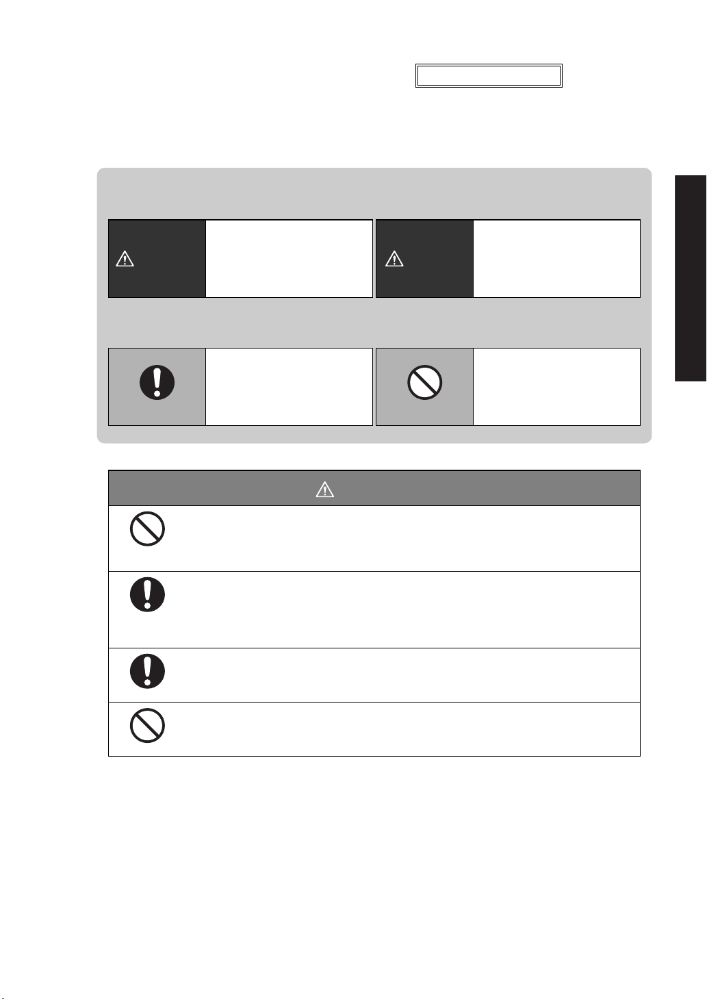
WARNING
Never disassemble, modify or attempt to repair this product or any
accessory.
Prohibitions
Instructions
Instructions
Prohibitions
You could sustain an electric shock or the product could operate abnormally.
If you believe that the balance has failed, contact your Shimadzu representative.
Use the balance with the specified power supply and voltage.
Using the balance with an incorrect power supply or voltage will lead to fire or trouble
with the balance.
Note also that if the power supply or voltage is unstable or if the power supply capacity
is insufficient, it will not be possible to obtain satisfactory performance from the balance.
Use the correct weighing units.
Using incorrect weighing units can lead to accidents as a result of weighing errors.
Check that the weighing units are correct before starting weighing.
Do not use the balance outdoors or anywhere where it will be exposed to
water.
You could sustain an electric shock or the product could operate abnormally.
For Basic Operation
- III -
Prohibitions
For Basic Operation
Instructions
Instructions
Instructions
Prohibitions
Instructions
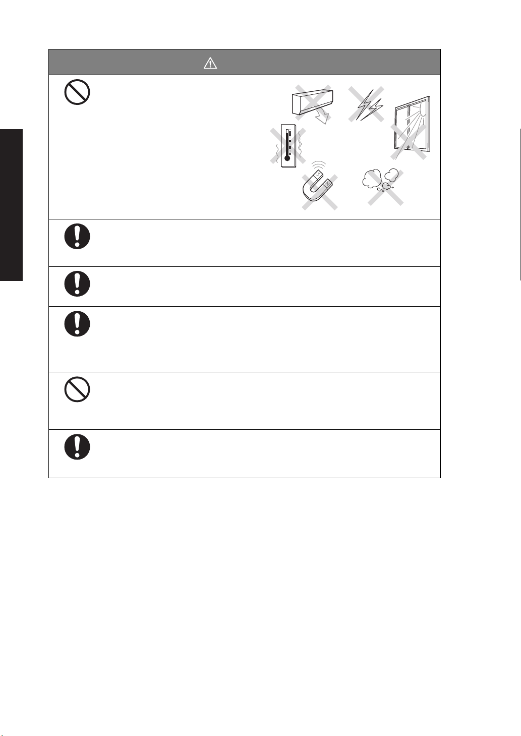
CAUTION
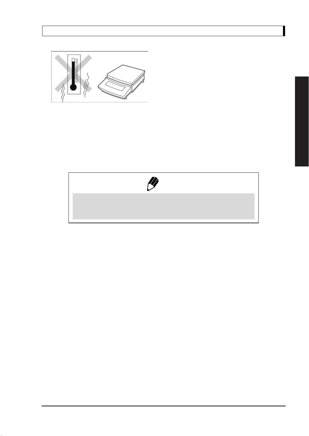
Avoid locations where the balance
will be exposed to any of the
following.
This could cause accidents or poor
performance.
• Air flow from an air conditioner,
ventilator, door or window
• Extreme temperature changes
•Vibration
• Direct sunlight
• Corrosive or flammable gases
• Dust, electromagnetic waves or a
magnetic field
Install the balance on a strong and stable flat table or floor.
Placing the balance in an unstable site could lead to injury or trouble with the balance.
When selecting the installation site, take into account the combined weight of the
balance and the item to be weighed.
After a power outage, turn the power back ON.
When a power outage occurs, the power is shut off automatically. Therefore, begin
operation from 4.4 “Turning ON the Power” (^ page 18) again.
Treat the balance with care and respect.
The balance is a precision instrument. Subjecting it to impacts could cause it to fail.
When moving the balance, remove pan and pan supporter. Grasp it firmly with both
hands to carry it.
If the balance has to be stored for a long time, store it in the packaging box in which it
was delivered.
Do not connect anything other than peripheral devices specified by
Shimadzu to the balance’s connector.
If you do, the balance may stop working normally.
In order to avoid trouble, always connect peripheral devices in accordance with the
directions in this manual.
If you detect anything abnormal (e.g. a burning smell) disconnect the AC
adapter immediately.
Continuing to use the balance with an abnormality could lead to fire or an electric
shock.
- IV -

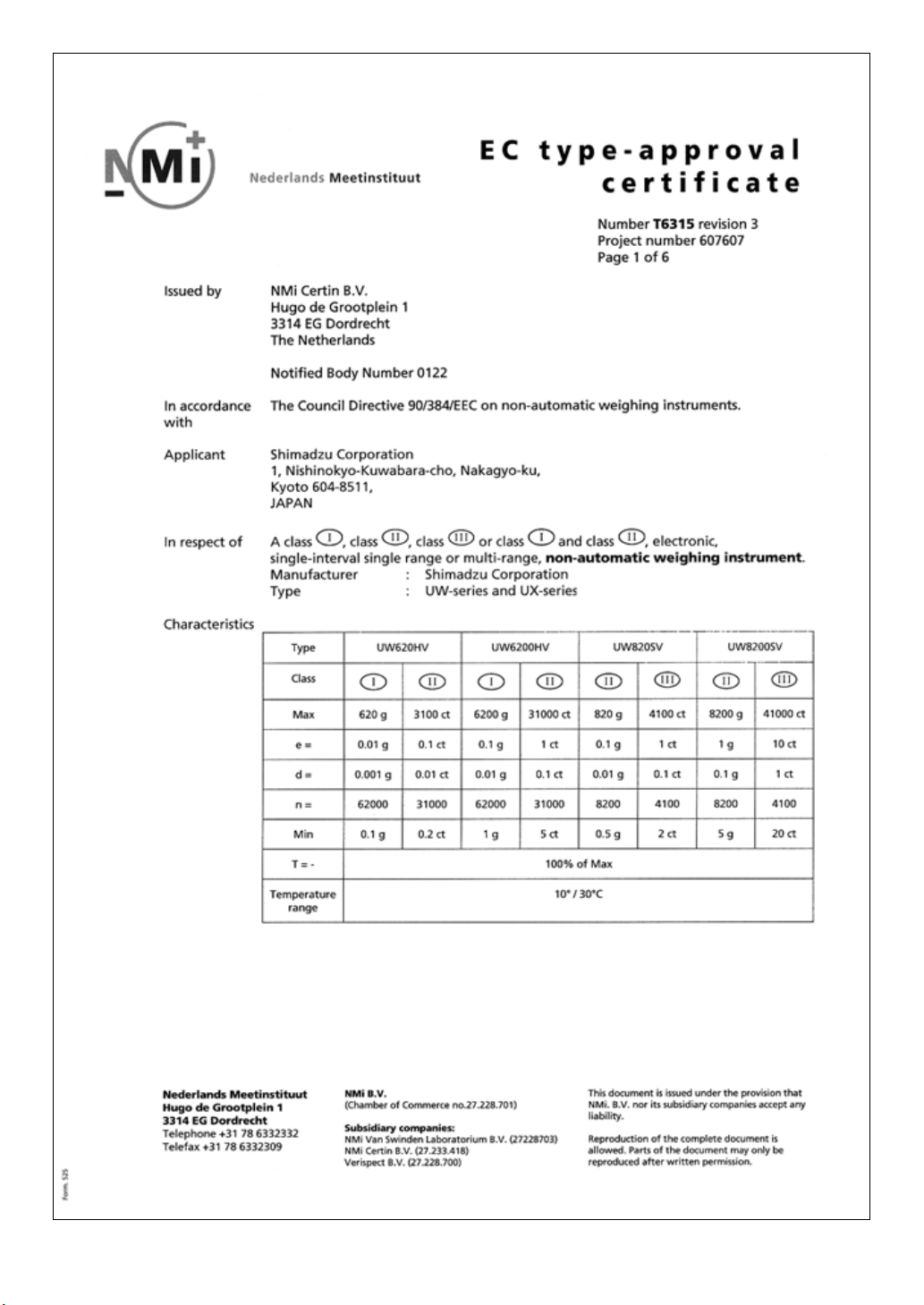
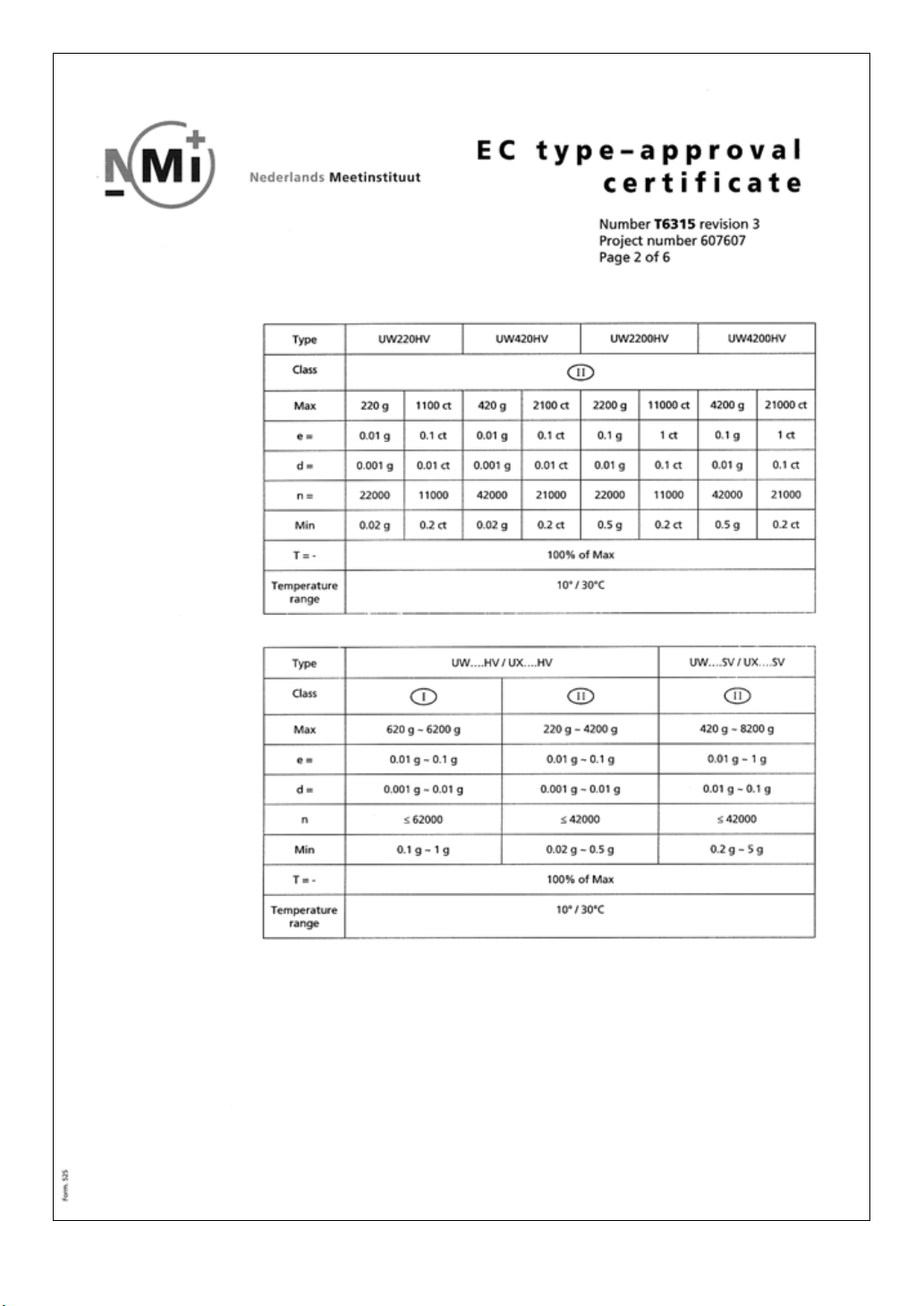
Declaration Of Conformity
Shimadzu Corporation declares that the following products:
UW Series and UX Series Electronic Balances
conform to the following directives.
Directives
EMC directive 89/336/EEC amended by 92/31/EEC, 93/68/EEC
EN55022: 1994 / A1: 1995 / A2: 1997 (Class B)
EN55024: 1998
EN61000-3-2: 1995 /A1: 1998 /A2: 1998, EN61000-3-3: 1995
Low Voltage directive 73/23/EEC amended by 93/68/EEC
EN60950: 1992 /A1: 1993 /A2: 1993
Weighing Instruments Department
Analytical & Measuring Instruments Division
SHIMADZU CORPORATION
1, Nishinokyo-Kuwabaracho
Nakagyo-ku, Kyoto-shi
604-8511 JAPAN
- V -
- VI -
- VII -

- VIII -

Shimadzu Balances and 21 CFR Part 11
21 CFR Part 11
21 CFR Part 11, Electronic Records, Electronic Signatures, Final
Rule (often referred to as Part 11) is the United States Food and
Drug Administration (FDA) regulation affecting computer resources
and electronic records that are used for any document that is
required to be kept and maintained by FDA regulations.
Requirements concerning computer resources security are key elements in Part 11.
The controls implemented as a result of security related requirements are intended to result in trusted records.
Shimadzu CLASS-Balance Agent
Shimadzu provides a means for compliance with 21 CFR Part 11
with Shimadzu CLASS-Balance Agent software, part of a comprehensive laboratory data management system, Shimadzu CLASS
Agent.
Ask your Shimadzu representative about it.
Shimadzu WindowsDirect
When Shimadzu balances are integrated with laboratory software by
means of our WindowsDirect function, no communication software is
required or used.
The Shimadzu balance functions as a primary device in the system,
just as a keyboard, mouse or other data entry hardware does.
For this reason, system validation and compliance may be greatly
simplified with the use of Shimadzu balances.
Two-way Communication
Shimadzu balances have always been computer friendly and they
can be set up for bi-directional communication as part of a fully automated production system or LIMS.
This manual includes the command codes and information needed
by programmers to integrate Shimadzu balances with their software.
- IX -

Action for Environment (WEEE)
To all user of Shimadzu equipment in the European Union:
Equipment marked with this symbol indicates that it was sold on or after 13th August 2005,
which means it should not be disposed of with general household waste. Note that our equip-
ment is for industrial/professional use only.
Contact Shimadzu service representative when the equipment has
reached the end of its life.
They will advise you regarding the equipment take-back.
With your co-operation we are aiming to reduce contamination from
waste electronic and electrical equipment and preserve natural
resource through re-use and recycling.
Do not hesitate to ask Shimadzu service representative, if you require
further information.
WEEE Mark
- X -

Contents
1. Introduction ........................................................................................................... 1
2. Name and Function of Components ......................................................... 2
2.1 Components ...................................................................................................... 2
2.2 Key Panel and Operation
2.3 Balance Display and Function
3. Specifications ....................................................................................................... 6
4. Installation ............................................................................................................. 8
4.1 Choosing the Installation Site ............................................................................. 8
4.2 Unpacking and Delivery Inspection ..................................................................... 10
4.3 Installation
4.4 Turning ON the Power
4.5 Span Calibration ............................................................................................... 19
......................................................................................................... 13
5. Basic Operation ................................................................................................... 22
5.1 Weighing ........................................................................................................... 22
5.2 Changing the Unit Display .................................................................................. 23
................................................................................... 4
............................................................................ 5
....................................................................................... 18
6. WindowsDirect Function ................................................................................ 24
6.1 Introduction: Experience it! ................................................................................. 24
6.2 Set Up WindowsDirect ....................................................................................... 24
6.2.1 Setting Up the Balance
6.2.2 Cable Connection
6.2.3 Setting Up the Computer ........................................................................ 25
6.2.4 Start and Checking Operation
6.3 Troubleshooting the WindowsDirect Communication Function
........................................................................... 24
.................................................................................. 25
................................................................. 27
............................. 28
7. Menu Item Selection ......................................................................................... 30
7.1 What is the Menu? ............................................................................................. 30
7.2 Menu Map
7.3 Menu Item Selection Procedure
7.4 Setting Numeric Values ...................................................................................... 33
7.5 Related Useful Functions
7.5.1 Last Menu Recall
7.5.2 Returning to the Default Settings (menu reset)
7.5.3 Menu Lock
......................................................................................................... 30
.......................................................................... 31
................................................................................... 34
................................................................................... 34
........................................ 34
............................................................................................. 35
- i -

Contents
8. Built-in Clock Set-up .......................................................................................... 36
8.1 Date ................................................................................................................... 36
8.2 Date Output Style
8.3 Time
8.4 Setting Display During Stand-by .......................................................................... 37
................................................................................................................... 37
............................................................................................... 36
9. Display Selection ................................................................................................. 38
9.1 Bar graph display ................................................................................................ 38
9.2 Changing the Minimum Display Digit (10d:1d)* .................................................... 38
10. Calibration ........................................................................................................... 39
10.1 What is calibration? ............................................................................................ 39
10.2 Calibration Execution ......................................................................................... 40
10.2.1 Span Calibration Using the Built-in Weight (UW Series Only)
10.2.2 Calibration Check Using the Built-in Weight (UW Series Only)
10.2.3 Span Calibration Using External Weights* ............................................... 42
10.2.4 Calibration Check Using External Weights*
10.3 Calibration Setting
10.3.1 Selecting the Calibration Type
10.3.2 PSC Fully-automatic Calibration (UW series only)
10.3.3 Clock-CAL Fully-automatic Calibration (UW series only) ........................... 45
10.3.4 PCAL: Calibration of the Built-in Weight (UW series only)*
10.3.5 PCAL Password Setting (UW series only)*
10.4 For GLP/GMP/ISO Conformance ........................................................................ 48
10.4.1 Calibration Report Setting ....................................................................... 48
10.4.2 Balance ID Setting
.............................................................................................. 44
................................................................. 44
.................................................................................. 48
.............................................. 43
.................................... 44
.............................................. 47
................... 40
.................. 41
....................... 46
11. Environment ....................................................................................................... 49
11.1 Overview ............................................................................................................ 49
11.2 Stability and Response (Averaging)
11.3 Stability Detection and Settings
11.3.1 Stability Detection Band .......................................................................... 51
11.3.2 Timing of Stability Mark Illumination and Data Output ............................... 52
11.4 Tracking
............................................................................................................. 52
..................................................................... 49
........................................................................... 50
12. Units ....................................................................................................................... 53
12.1 Unit Display Set-up ............................................................................................ 53
12.2 Percentage (%) Conversion
*Not applicable to a verified balance as a legal measuring instrument in the EU
................................................................................ 54
- ii -

Contents
13. Enhancing Productivity ............................................................................... 55
13.1 Checkweighing and Target Display ..................................................................... 55
13.1.1 Checkweighing (Comparator) Display Type 1
13.1.2 Checkweighing (Comparator) Display Type 2
13.1.3 Target Mode .......................................................................................... 57
13.2 Piece Counting (PCS)
13.3 Auto Print
13.4 Auto Zero* ......................................................................................................... 61
13.5 Zero Range
13.6 Taring/Printing at Stability*
13.7 Pretaring Value* ................................................................................................ 64
.......................................................................................................... 59
....................................................................................................... 62
........................................................................................ 58
................................................................................. 63
.......................................... 56
.......................................... 56
14. Application Functions .................................................................................. 65
14.1 Solid Specific Gravity Measurement ................................................................... 65
14.2 Liquid Density Measurement .............................................................................. 67
14.3 Peak Hold*
14.4 Interval Timer*
14.5 Add-on Mode ..................................................................................................... 72
14.6 Animal Weighing*
14.7 Formulation Mode
........................................................................................................ 69
................................................................................................... 71
.............................................................................................. 74
.............................................................................................. 77
15. Connecting Peripheral Instruments ...................................................... 79
15.1 Electronic Printer ............................................................................................... 79
15.2 Personal Computer - RS-232C -
15.2.1 Connecting the Cable ............................................................................ 80
15.2.2 Data Format
15.2.3 Using Command Codes ......................................................................... 83
15.2.4 Multi-Connection Mode
15.3 Communication Setting
15.3.1 Overview
15.3.2 Handshaking
15.3.3 Format ................................................................................................... 92
15.3.4 Communication Speed
15.3.5 Parity / Bit Length
15.3.6 Stop Bit .................................................................................................. 92
15.3.7 Delimiter
15.4 Decimal Point Symbol in Output Data
........................................................................................... 81
...................................................................................... 91
............................................................................................... 91
.......................................................................................... 91
................................................................................................ 93
......................................................................... 80
.......................................................................... 88
........................................................................... 92
................................................................................... 92
................................................................. 93
16. Maintenance and Transportation ........................................................... 94
16.1 Maintenance ...................................................................................................... 94
16.2 Moving the Balance ........................................................................................... 94
*Not applicable to a verified balance as a legal measuring instrument in the EU
- iii -

Contents
17. Troubleshooting ............................................................................................... 95
17.1 General Display .................................................................................................. 95
17.2 Error Display
17.3 Troubleshooting
17.4 LCD (Liquid Crystal Display) Check ..................................................................... 97
Appendices ..................................................................................................................... 98
A-1. Menu Map .......................................................................................................... 98
A-2. Standard Accessories and Maintenance Parts List
A-3. Optional Accessories List ................................................................................... 104
A-4. Specifications of Connectors ............................................................................... 105
A-5. Table of Unit Conversion Constants
A-6. Performance Checks .......................................................................................... 107
A-7. Below-Weigh Hook Dimensions .......................................................................... 108
A-8. Index
.................................................................................................................. 109
...................................................................................................... 96
.................................................................................................. 97
............................................... 103
.................................................................... 106
- iv -
1. Introduction
1. Introduction
Shimadzu UW/UX series of toploading balances are a product of our 80 year history of developing and
manufacturing weighing instruments.
Shimadzu UW/UX series of toploading balances utilize the patented Shimadzu UniBloc sensor, intro-
duced in 1989, to achieve high performance, fast response, and durability. Available features include
multiple units of measure, piece counting, checkweighing functions, auto print, and GLP/GMP/ISO out-
put including date and time data from a built-in clock.
The new series also features Shimadzu’s WindowsDirect communication, requiring no software instal-
lation to quickly integrate balances with lab or business software. This function eliminates data input
errors and offers extensive flexibility for application development without compromising compliance or
data security.
The UW series balance incorporates a motor-driven built-in calibration weight that can automatically
calibrate sensitivity without the use of external weights.
Read this manual carefully before using this instrument and keep it with the balance for future refer-
ence.
For Basic Operation
This manual refers to the different types of UW and UX series (UW/UX series) balances as follows:
H type: UW/UX H
S type: UW/UX S
Where: represents the figure indicating the capacity, H indicates high resolution and
S indicates standard resolution.
Suffix “V” is added for models with EC Type Approval.
The type of balance is classified as “large pan” or “small pan” depending on the capacity. The small
pan models with minimum display of 0.001g come with a standard windbreak. Accordingly, the models
are classified into the following three groups in “4. Installation”.
a. Large pan models: Capacity 2200g or higher
b. Small pan models: Capacity 820g or lower (minimum display 0.01g)
c. Small pan models: Capacity 820g or lower (minimum display 0.001g, windbreak standard)
For information on the following points, please contact your Shimadzu Balance representative.
• Product warranty
• After service
1
2. Name and Function of Components
2. Name and Function of Components
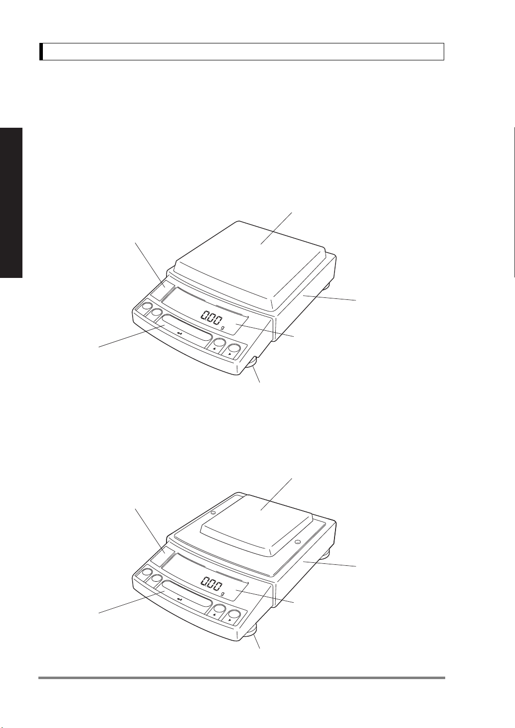
2.1 Components
a. Large pan model
Label
(Shows model name. "Max", "Min", "e" and "d"
are indications required by legal metrology,
which do not restrict the weighing range
in general use.)
For Basic Operation
Operation keys
(Used to tare, execute calibration
and functions, program functions,
input numerical values)
b. Small pan model (minimum display 0.01g)
Label
(Shows model name. "Max", "Min", "e" and "d"
are indications required by legal metrology,
which do not restrict the weighing range
in general use.)
Pan
(Supports the object to be weighed)
Main body
Display panel
(Shows weighed result, information on
programming function, indicates current
setting, working function, necessary
operation, and error message)
Level screws
(Adjust to level the balance)
Pan
(Supports the object to be weighed)
Operation keys
(Used to tare, execute calibration
and functions, program functions,
input numerical values)
2
Main body
Display panel
(Shows weighed result, information on
programming function, indicates current
setting, working function, necessary
operation, and error message)
Level screws
(Adjust to level the balance)

2. Name and Function of Components
r
c. Small pan model (minimum display 0.001g, windbreak standard)
Pan
(Supports the object to be weighed)
Label
(Shows model name.
"Max", "Min", "e" and "d"
are indications required by
legal metrology, which do not
restrict the weighing range
in general use.)
Operation keys
(Used to tare, execute calibration
and functions, program functions,
input numerical values)
a, b, c. common
Windbreak set
(Included with models with
minimum display of 0.001g.
Prevents possible affect by air flow)
For Basic Operation
Main body
Display panel
(Shows weighed result, information on
programming function, indicates current
setting, working function, necessary
operation, and error message)
Level screws
(Adjust to level the balance)
Below-weigh hook cap
Below-weigh hook cap
Theft preventing ring
RS-232C
Connector
DATA I/O
Connector
(Connectors on the back)
KEY Connector
AUX
Connector
DC IN
Connecto
3
2. Name and Function of Components
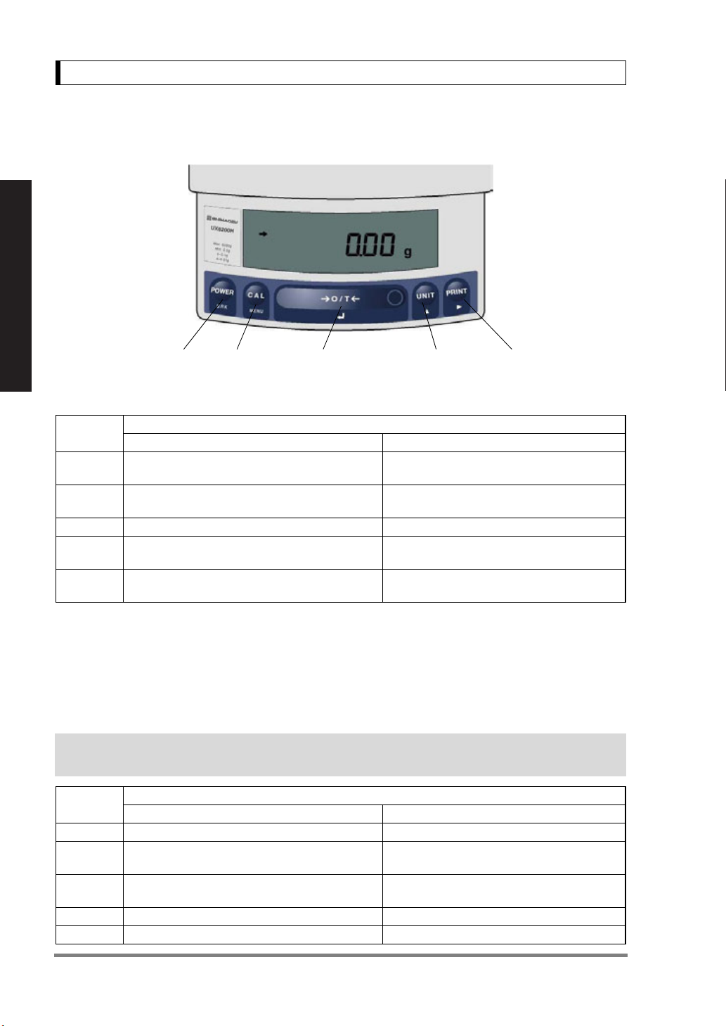
2.2 Key Panel and Operation
For Basic Operation
[POWER] key [CAL] key [O/T] key [UNIT] key [PRINT] key
Functions of the keys
Key
[POWER]
[CAL]
[O/T] Tares the balance. (Displays zero.) (*2) (*5) (*6) Displays the Pretare value.(*7)
[UNIT]
[PRINT] Sends the displayed value to a peripheral device.
*1 This key is used to set values when percent (%), number (PCS), solid specific gravity (Td), or liquid specific
gravity (d) are displayed.
*2 When a Pretare value is set, zero is not displayed and [-Pretare value] is displayed. (*7)
*3 Units other than “g” must be set up before they can be used for measurement. Only gram (g), percent (%), and
piece counting (PCS) are set-up before shipment. To set up other units or specific gravity measurement, refer
to section 12., or 14.1, 14.2.
*4 When the unit is set to 10d, the resolution of the minimum display is decreased by one decimal place.
*5 In Pouring mode (See 11. 2), the right-most part of [O/T] key marked with a circle functions as the switch for
environmental condition setting. Otherwise this part functions the same way as the other parts of [O/T] key.
*6 Either “Taring” (at a weight exceeding 2.0% of the capacity) or “Zeroing” ( at a weight within 2.0% of the capac-
ity) takes place with a verified balance as a legal measuring instrument in the EU.
*7 Not applicable to a verified balance as a legal measuring instrument in the EU.
Switches between the operation and standby
modes.
Enters span calibration or menu item selection.
(*1)
Changes the weighing unit or selects specific
gravity measurement. (*3)
Press Once and Release Press and Hold for About 3 Seconds
During Weighing
Exits the application function and returns to
the mass display.
Displays the last menu item that was set.
(Last menu recall)
Switches between the 1d and 10d display. (*4)
(*7)
Sends the date and time to a peripheral
device.
Key
[POWER] Returns to the previous menu level Returns to the mass display.
[CAL] Moves to the next menu item.
[O/T]
[UNIT] Increases the numeric value of the blinking digit by 1. No operation.
[PRINT] Moves to the next digit during numeric value entry. No operation.
Selects or sets the currently displayed menu item,
or enter into the displayed menu.
Press Once and Release Press and Hold for About 3 Seconds
During Menu Item Selection
Displays the last menu item that was set.
(Last Menu Recall)
No operation.
4
2. Name and Function of Components
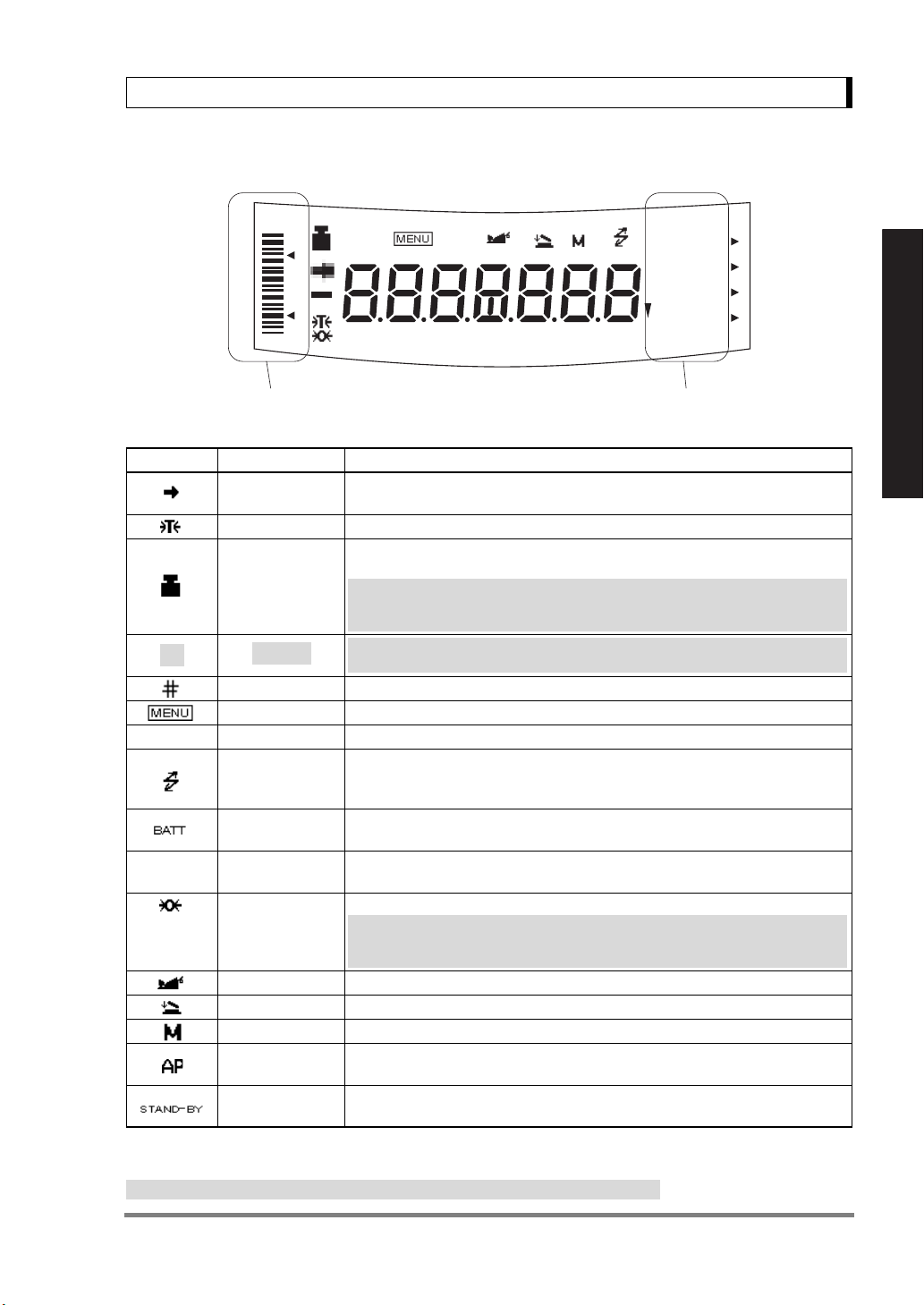
2.3 Balance Display and Function
HI
# ∗
%NETBPTG
PCS lbGN
GO
LO
Analog display section Unit display section
Display Name Description
Stability mark
Tare symbol Indicates that a Pretare value has been set.(*2)
[ ] Bracket
∗ Asterisk Indicates that the displayed numeric value is not a mass value.
T
*1 Stability mark
The displayed value may change while the stability symbol remains illuminated if the load is changing slowly or
if the stability detection band has been set to a large value.
*2 Not applicable to a verified balance as a legal measuring instrument in the EU
Weight symbol
Number symbol Indicates numeric value entry.
Menu symbol Indicates that the menu lock is on. Illuminates during menu item selection.
Communication
symbol
Battery symbol
Inverse triangle
symbol
Zero symbol Indicates the set-up of Auto Zero function.(*2)
Animal symbol Indicates the set-up of Animal Weighing function.(*2)
Add-on symbol Indicates the set-up of Add-on mode or Formulation mode.
Memory symbol Indicates the set-up of Formulation mode.
Auto Print
symbol
Stand-by symbol Illuminates when the balance power is in the standby mode.
BATT
Indicates that the weighed value is stable. (*1) In menu item selection, indicates currently selected item.
Illuminates during span calibration. In menu selection, indicates setting related
to calibration. Blinks before automatic span calibration starts.
Note: Using a verified balance as a legal measuring instrument in the EU:
When PSC fully-automatic span calibration is not activated, operator must
carry out span calibration with the built-in weight upon blinking of this symbol.
Note: Using a verified balance as a legal measuring instrument in the EU:
The figure bordered by the bracket is the auxiliary indicating device.
Illuminates during communication to external equipment through the RS232C or DATA I/O connector. In menu selection, indicates setting related to
communication.
When the balance is operated with the optional battery pack, this symbol illuminates to indicate that the battery voltage has dropped.
Indicates the set-up of solid specific gravity measurement. Used as a substitute for the decimal point.
Note: Using a verified balance as a legal measuring instrument in the EU:
Indicates that the balance is set exactly to "Zero" with the zero-setting function(+/-0.20e: e = verification scale interval).
Indicates the set-up of Auto Print function.
Also illuminates when the application function has entered the standby mode.
AP WARM-UP STAND-BY
mg mom
ctdwt
kg
oztl
For Basic Operation
5

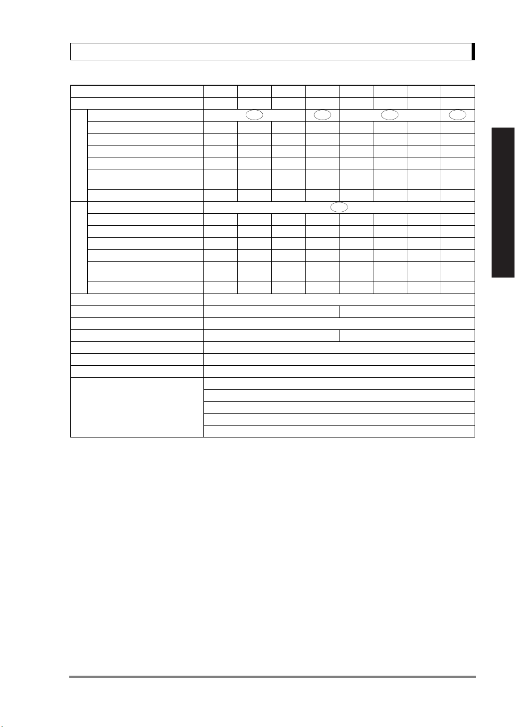
3. Specifications
3. Specifications
UW Series Model UW220H UW420H UW620H UW2200H UW4200H UW6200H UW420S UW820S UW4200S UW8200S
Capacity 220g 420g 620g 2200g 4200g 6200g 420g 820g 4200g 8200g
Minimum display 0.001g 0.001g 0.001g 0.01g 0.01g 0.01g 0.01g 0.01g 0.1g 0.1g
Calibration range
with external weights
Repeatability (σ) ≤0.001g ≤0.01g ≤0.008g ≤0.08g
Linearity ±0.002g ±0.02g ±0.01g ±0.1g
Response time (s) 1.5 - 2.5 0.7 - 1.2
Ambient temperature (°C)
Temperature coefficient of sensi-
For Basic Operation
tivity (ppm/°C) (10 - 30°C)
Pan size (mm) approx.
Main body dimensions (mm) approx.
Weight (kg) approx. 3.4 4.6 3.4 4.6
Display LCD with backlight
Power requirements DC, 10 to 15.5V, 500mA (plug polarity: center negative)
Data I/O RS-232C
Features
100 - 220g 100 - 420g 100 - 620g
108 X 105 170 X 180 108 X 105 170 X 180
Analog display, % display, PCS, User unit, Animal weighing, Specific gravity measurement S/W, Checkweighing
1000 - 2200g 1000 - 4200g 1000 - 6200g
5 - 40
±3 ±5
190W X 317D X 78H
WindowsDirect
PSC
Clock-CAL
GLP/GMP/ISO conformance
100 - 420g 100 - 820g
1000 - 4200g 1000 - 8200g
UX Series Model UX220H UX420H UX620H UX2200H UX4200H UX6200H UX420S UX820S UX4200S UX8200S
Capacity 220g 420g 620g 2200g 4200g 6200g 420g 820g 4200g 8200g
Minimum display 0.001g 0.001g 0.001g 0.01g 0.01g 0.01g 0.01g 0.01g 0.1g 0.1g
Calibration range
with external weights
Repeatability (σ) ≤0.001g ≤0.01g ≤0.008g ≤0.08g
Linearity ±0.002g ±0.02g ±0.01g ±0.1g
Response time (s) 1.5 - 2.5 0.7 - 1.2
Ambient temperature (°C)
Temperature coefficient of sensitivity (ppm/°C) (10 - 30°C)
Pan size (mm) approx.
Main body dimensions (mm) approx.
Weight (kg) approx. 2.7 2.9 2.7 2.9
Display LCD with backlight
Power requirements DC, 10 to 15.5V, 500mA (plug polarity: center negative)
Data I/O RS-232C
Features
100 - 220g 100 - 420g 100 - 620g
108 X 105 170 X 180 108 X 105 170 X 180
Analog display, % display, PCS, User unit, Animal weighing, Specific gravity measurement S/W, Checkweighing
1000 - 2200g 1000 - 4200g 1000 - 6200g
5 - 40
±3 ±5
190W X 317D X 78H
WindowsDirect
GLP/GMP/ISO conformance
100 - 420g 100 - 820g
1000 - 4200g 1000 - 8200g
6
3. Specifications
UW Series (ECTA) Model
UX Series (ECTA) Model
g Accuracy class IIIIII
Capacity 820g 220g 420g 620g 8200g 2200g 4200g 6200g
Verification scale interval (e) 0.1g 0.01g 0.01g 0.01g 1g 0.1g 0.1g 0.1g
Number of verification scale interval 8200 22000 42000 62000 8200 22000 42000 62000
Scale interval (d) 0.01g
Range of use 0.5g -
Tare range (by subtraction) -820g -220g -420g -620g -8200g -2200g -4200g -6200g
ct Accuracy class II
Capacity N/A 1100ct 2100ct 3100ct N/A 11000ct 21000ct 31000ct
Verification scale interval (e) N/A 0.1ct 0.1ct 0.1ct N/A 1ct 1ct 1ct
Number of verification scale interval N/A 11000 21000 31000 N/A 11000 21000 31000
Scale interval (d) N/A 0.01ct 0.01ct 0.01ct N/A 0.1ct 0.1ct 0.1ct
Range of use N/A
Tare range (by subtraction) N/A -1100ct -2100ct -3100ct N/A
Ambient operating temperature(°C) 10 - 30
Pan size (mm) approx. 108 X 105 170 X 180
Main body dimensions (mm) approx. 190W X 317D X 78H
Weight (kg) approx. 3.4 4.6
Display LCD with backlight
Power requirements DC, 10 to 15.5V, 500mA (plug polarity: center negative)
Data I/O RS-232C
Features
UW820SV UW220HV UW420HV UW620HV
UX820SV UX220HV UX420HV UX620HV
0.001g 0.001g 0.001g
820g
0.02g 220g
N/A
0.2ct 1100ct
Analog display, % display, PCS, Specific gravity measurement S/W, Checkweighing
0.02g 420g
0.2ct -
2100ct
0.2ct -
3100ct
GLP/GMP/ISO conformance
UW8200SV UW2200HV UW4200HV UW6200HV
UX8200SV UX2200HV UX4200HV UX6200HV
0.1g 0.01g 0.01g 0.01g
0.1g 620g
WindowsDirect
5g -
8200g
N/A
N/A
PSC (UW***V only)
Clock-CAL (UW***V only)
0.5g -
2200g
5ct -
11000ct
-11000ct -21000ct -31000ct
0.5g -
4200g
5ct -
21000ct
1g -
6200g
For Basic Operation
5ct -
31000ct
7
4. Installation
4. Installation
4.1 Choosing the Installation Site
(1) Power supply
• Select an installation site that is near a power source to ensure that the attached AC adapter
is used properly. If this is not possible, an optional battery pack is available as a special
accessory.
• Verify that the supply power voltage conforms to that indicated on the AC adapter.
For Basic Operation
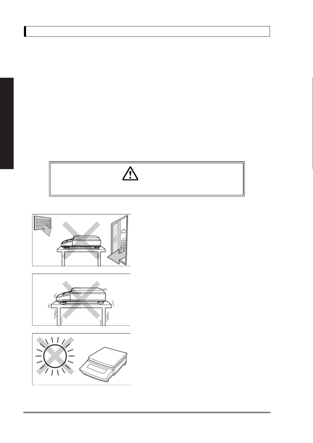
(2) Installation site
Caution
Avoid sites where the balance will be exposed to the following:
• Air flow from air-conditioner, open window, or venti-
lator
•Vibration
• Direct sunlight
(Continued)
8
4. Installation
• Extreme temperature, temperature changes or
humidity
• Corrosive or flammable gasses
• Dust, wind, electromagnetic waves, or magnetic fields
Large capacity balances should be installed on a sturdy floor and table that can support the total load
of the balance AND object to be weighed.
Note
Using a verified balance as a legal measuring instrument in the EU:
The balance must be used within the temperature range indicated on the
verification label.
For Basic Operation
9

4. Installation
4.2 Unpacking and Delivery Inspection
Unpack and remove all the items from the delivery box. Check if all the listed items are present and
nothing has been damaged. Contact your local distributor in case of damaged or missing items.
Standard packed item and quantity
Type a. Large pan model
Model
(UW/UX is “UW or UX”. Additional
suffix may appear after H or S on
For Basic Operation
your balance.)
Balance main body 111
Pan supporter cap 444
Pan 111
AC adapter 111
In-use protective cover 111
Main 001
Windbreak set
Rubber cap 0
Stainless screw 022
Instruction manual (incl. explanatory operation sheet)
Lid 001
Fixing knob 002
UW/UX2200H,
UW/UX4200H,
UW/UX6200H,
UW/UX4200S,
UW/UX8200S
111
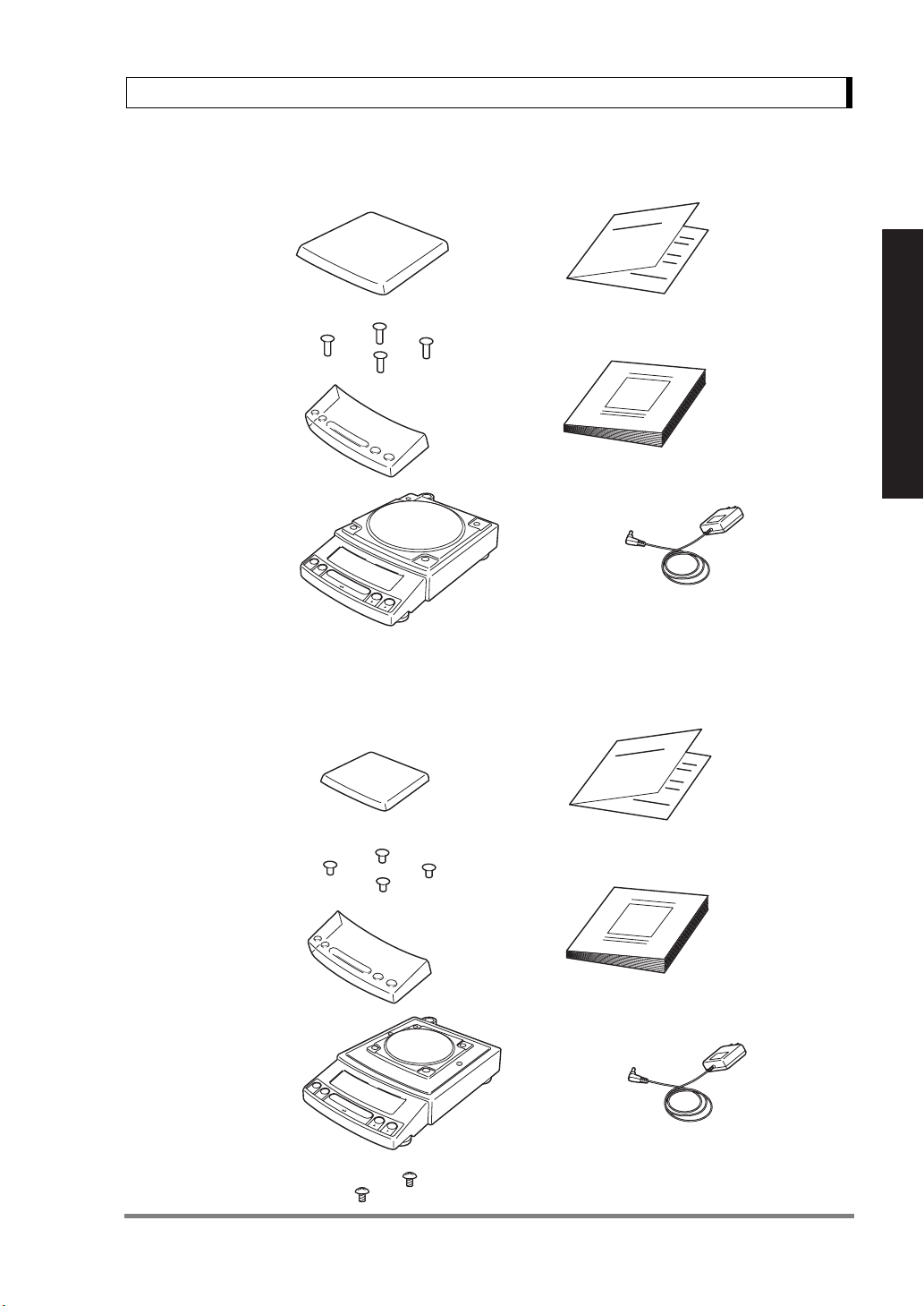
b. Small pan model
(Minimum display 0.01g)
UW/UX420S,
UW/UX820S
2 (installed on balance
main body)
c. Small pan model
(Minimum display 0.001g)
UW/UX220H,
UW/UX420H,
UW/UX620H
2 (installed on balance
main body)
10
a. Large pan model
4. Installation
Pan
Pan supporter caps
In-use protective
cover
Balance
main body
b. Small pan model (minimum display 0.01g)
Pan
Explanatory operation sheet
For Basic Operation
Instruction manual
AC adapter
(The shape of the adapter supplied with
the balance may differ from this figure.)
Pan supporter caps
In-use protective
cover
Balance main body
(with rubber caps)
Stainless screws
Explanatory operation sheet
Instruction manual
AC adapter
(The shape of the adapter supplied with
the balance may differ from this figure.)
11
4. Installation
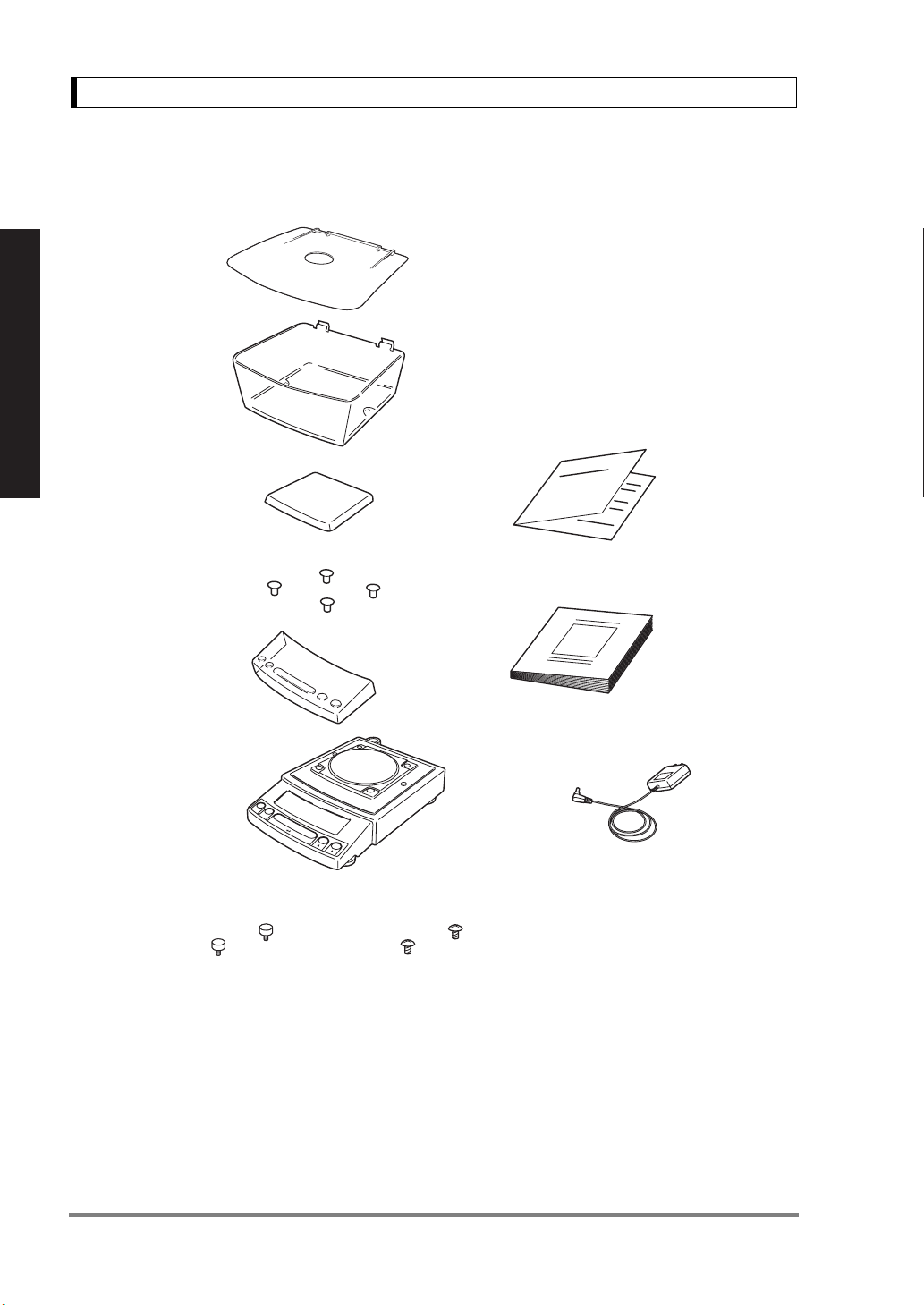
c. Small pan model (minimum display 0.001g)
Windbreak Lid
Windbreak Main
For Basic Operation
Pan
Pan supporter caps
In-use protective
cover
Balance main body
(with rubber caps)
Explanatory operation sheet
Instruction manual
AC adapter
(The shape of the adapter supplied with
Stainless screwsFixing knobs for windbreak
the balance may differ from this figure.)
12
4. Installation
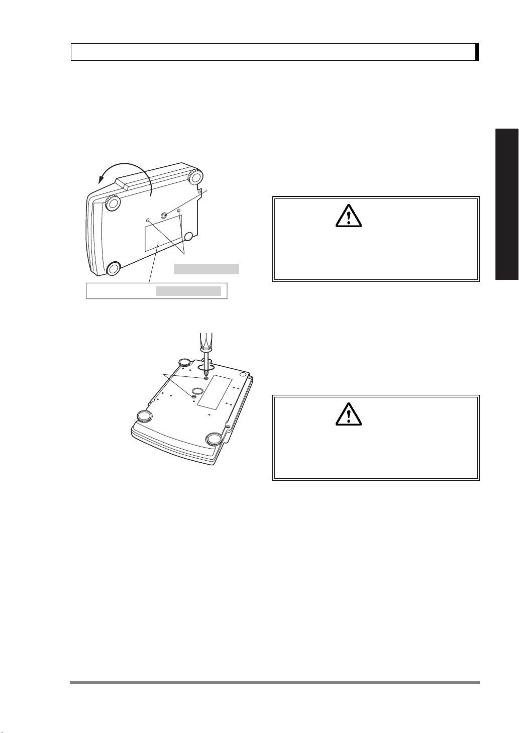
4.3 Installation
(Start at step 3 when installing a UX series balance. Prepare a plus (+) screw driver for a UW series
balance.)
1 Place the balance main body upside down.
Below-weigh
hook cap
(UW only)
Caution
Transportation screws
(only for UW series)
Explanation label (only for UW series)
Transportation screws
Do not operate step 2 with the balance placed
on its side.
Place the balance on a smooth surface.
2 Referring to the explanation label on the bottom
of the balance, turn the two transportation screws
counterclockwise until they tighten again.
(UW only)
Caution
When moving the balance again, turn the two
transportation screws clockwise until they
tighen. (UW only)
For Basic Operation
13
4. Installation
3
Level
screw
Left front
For Basic Operation
2
[Large pan model]
Level indicator
Level screw
(At the shortest
point when
starting
adjustment)
3
Level screw
1
3 This balance has three level screws (adjustable
feet) at the right front, left front and right rear cor-
ners.
Turning a level screw clock-wise stretches the leg
to raise the balance body there. Turning anti-
clockwise withdraws the leg and lowers the bal-
ance body.
The level indicator locates at left rear. The bubble
of it is off center when the balance is not placed
level.
(1) Adjustment is made with the two front level
screws only. Accordingly, first turn the right rear
level screw
leg completely.
(2) While adjusting level screws and observing
the bubble, gently press the left front corner of
the balance
feet
3 are touching the table surface.
1 anti-clockwise to withdraw its
2 so that both front level screw
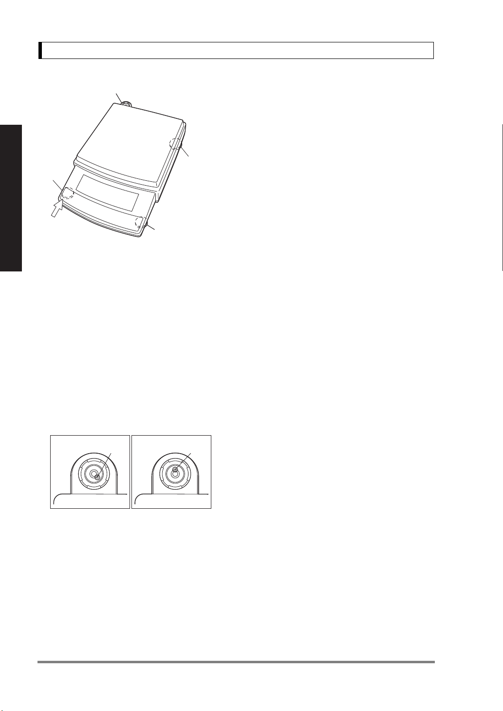
Case 1 Case 2
Bubble Bubble
(3) Bubble moves to the highest position. There-
fore, adjust level screws
main body is lowered in the direction of the
bubble.
Case 1: Right front of the balance is too high.
Turn right front level screw anti-clockwise so
that the bubble moves towards center.
Case 2: Front of the balance is too low. Turn
both front level screws clockwise so that the
bubble moves towards center.
(4) When the bubble has come to the center of
the red circle, turn the right rear level screw
clockwise until its foot softly touches the table
surface. Verify the balance sits stable with four
feet.
3 so that the balance
14
 Loading...