

Shimadzu UV-1700 series Service Manual

206-98366A
UV-Vis Spectrophotometer
UV-1700 series
SERVICE MANUAL
206-55401-34 for 230V CE
206-55401-91 for 100V
206-55401-92 for 120V
206-55401-93 for 220V
206-55401-94 for 240V
SHIMADZU CORPORATION
ANALYTICAL INSTRUMENTS DIVISON
KYOTO JAPAN

Contents
1. Introduction 1-1
1.1 About the Service Manual 1-2
1.2 UV-1700 Outline 1-2
1.3 Intended Use 1-2
1.4 Warning Labels on Instrument 1-3
2. Installation 2-1
2.1 Inspection of Parts 2-2
2.2 Selection of Installation Site 2-4
2.3 Installation of UV-1700 2-5
2.4 Instrument Baseline Correction 2-6
3. Performance Checks 3-1
3.1 Notes on the Performance Checks 3-2
3.2 How to Use Instrument Validation 3-3
3.3 ROM Check 3-6
3.4 Wavelength Accuracy 3-7
3.5 Wavelength Repeatability 3-10
3.6 Resolution 3-11
3.7 Baseline Stability 3-12
3.8 Baseline Flatness 3-13
3.9 Noise Level 3-15
3.10 Photometric Accuracy 3-17
3.11 Photometric Repeatability 3-20
3.12 Stray Light 3-22
4. Acceptance Procedures 4-1
4.1 Acceptance Procedures 4-2
5. Periodical Check 5-1
5.1 Daily Checks 5-2
5.2 Monthly Checks 5-2

6. Troubleshooting 6-1
6.1 An Error Occurs During Initialization 6-2
6.2 Baseline Flatness Exceeds Specification 6-5
6.3 Noise Level Exceeds Specification 6-5
6.4 Wavelength Accuracy Exceeds Specification 6-6
6.5 Wavelength Repeatability Exceeds Specification 6-6
7. Parts Replacement 7-1
7.1 Main Unit Cover Removal 7-2
7.2 Console PCB Removal 7-3
7.3 Preamplifier PCB Removal 7-3
7.4 Power PCB Removal 7-4
7.5 CPU PCB Removal 7-4
7.6 ROM Replacement 7-5
7.7 Battery Replacement 7-5
8. Adjustment Procedures 8-1
8.1 Jigs and Tools Required 8-2
8.2 Before Starting Adjustment 8-3
8.3 Adjustments 8-17
9. Configuration 9-1
9.1 Optical System 9-2
9.2 Beam Position in Sample Compartment 9-4
9.3 Electric System 9-5
9.4 Instrument Assignment Explanation 9-6
10. Parts List 10-1
10.1 Instrument Configuration List 10-2
10.2 UV-1700 Main Unit 10-3
10.3 Main Unit 10-4
10.4 Cover Unit 10-5
10.5 Transformer Assy 10-6
10.6 Light Source Assy 10-7
10.7 Optical Unit Assy 10-8
10.8 Cell Housing Assy 10-9
10.9 Slit & Filter Assy 10-10
10.10 PCB ASSY, CPU 10-11
10.11 PCB ASSY, Power 10-14
10.12 PCB ASSY, Preamp 10-15

10.13 PCB ASSY, Console 10-16
11. Electric Circuit Diagram 11-1
11.1 Electrical Block Diagram 11-2
11.2 CPU P.C.Board 11-3
11.3 Preamp P.C.Board 11-9
11.4 Power P.C.Board 11-10
11.5 Console P.C.Board 11-11

Chapter 1
Introduction
This chapter explains instrument outline, intended use of
service manual and warning labels.
1.1 About the Service Manual
1.2 UV-1700 Outline
1.3 Intended Use
1.4 Warning Labels on Instrument
1-1

1.1 About the Service Manual
This service manual explains the procedures for installing, performance checking,
troubleshooting and adjusting for the UV-Vis Spectrophotometer UV-1700.
1.2 UV-1700 Outline
UV-1700 PharmaSpec - a spectrophotometer for ultraviolet and visible region that is the first
in its class to amply clear the 1nm resolution barrier to conform to wavelength resolution
regulations specified in the European Pharmacopoeia - is a sister instrument to the highly
rated UV-1600.
The UV-1700 has the following features.
Conforms to specifications and functions (wavelength accuracy, resolution and
photometric accuracy, etc.) laid down in the European, USA and Japanese
Pharmacopoeias.
Provided with hardware validation functions as standard.
Supports IQ and OQ.
Compact, light spectrophotometer
LCD and designated keys enhance ease of operation.
1.3 Intended Use
Receiving service training is a prerequisite for the correct use of this manual.
Note that Shimadzu will not bear responsibility for problems that may occur when a person
who has not received specific service training operates the instrument according to this
manual.
1-2
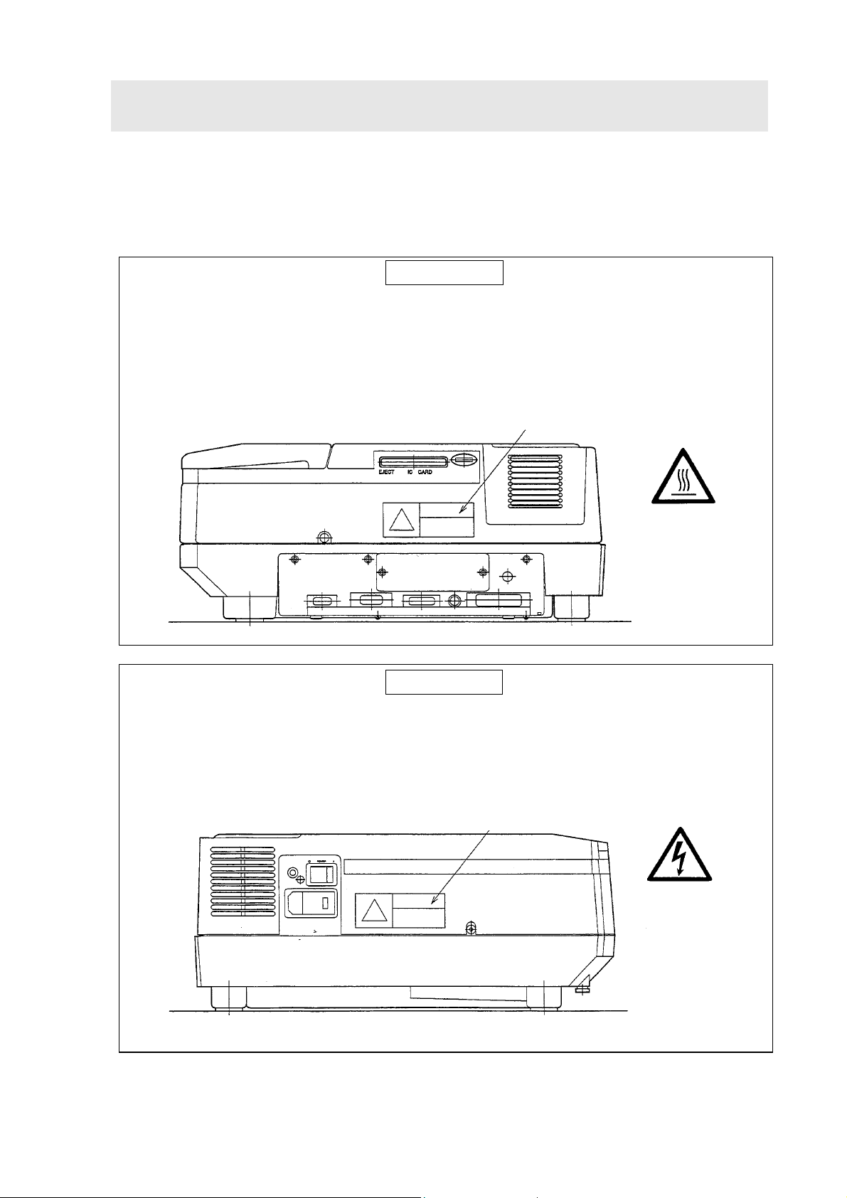
1.4 Warning Labels on Instrument
Warning labels are attached to the UV-1700 in the following two locations. Be sure to
thoroughly read the instruction manual in advance and adhere to instructions provided
when replacing lamps or fuses to avoid injuries such as burns and electric shocks.
WARNING
DANGER, High Temperature
The light source and light source compartment become extremely hot during operation.
To replace the lamp, turn the power OFF, wait at least ten minutes for the lamp to
sufficiently cool. Check that the lamp has cooled down, and then replace.
Warning label
WARNING
DANGER, Electric Shock
Be sure to turn OFF power and disconnect power cable before replacing a fuse to avoid
electric shock.
Warning label
1-3

Chapter 2
Installation
This chapter explains how the UV-1700 is installed. Be sure to
adhere to the procedures in this chapter when performing
installation work so that the instrument performs appropriately
to ensure customer satisfaction.
2.1 Inspection of Parts
2.2 Selection of Installation Site
2.3 Installation of UV-1700
2.4 Instrument Baseline Correction
2-1
2.1 Inspection of Parts
UV-1700 standard contents are shown in Table 2.1 and figure 2.1. Check these together with the
customer to see that all parts have been delivered.
Table2-1 Standard Contents
Description P/N Qty.
1 Spectrophotometer UV-1700 Main unit
For 230V CE area
For 100V area
For 120V area
For 220V area
For 240V area
2 Standard Accessories (One of the following)
For 100V-120V area
For 220V-240V area
2-1 AC Power Cable (One of the following)
For 100V-120V area
For 220V-240V area
2-2 Fuse (One of the following)
4.0A (For 100V-120V) area
2.0A (For 220V-240V) area
2-3 Grounding Adaptor ( For100V-120V only ) 071-60803-01 1
206-55403-34
206-55403-91
206-55403-92
206-55403-93
206-55403-94
206-67099
206-67099-01
071-60814-01
071-60814-05
072-02004-22
072-02004-19
1
1
2
3 Instruction Manual
(Installation & Maintenance)
4 Instruction Manual (Operation) 206-94785 1
5 Certificate of Compliance 206-84934-56 1
206-94783 1
2-2
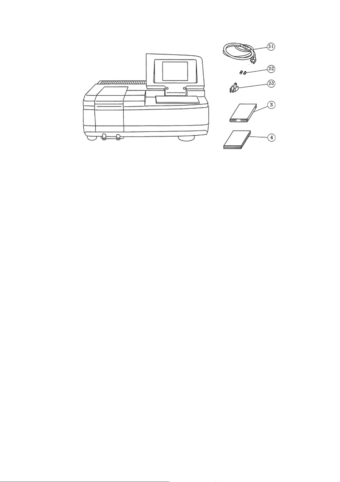
Fig.2-1 Standard contents (items 5 is not displayed)
2-3

2.2 Selection of Installation Site
Meet with the customer and decide upon a suitable installation site before commencing
installation of the UV-1700. And be sure to install the instrument in a site that conforms to
the following parameters to ensure that the instrument will perform appropriately and
stably over a long period.
Room temperature: 15°C to 35°C
Out of direct sunlight
No strong vibration or continuous weak vibration
Away from devices emitting strong magnetic fields, electromagnetic fields or high
frequencies
Humidity: 45% to 80%
Away from corrosive gases and organic or non-organic gases with absorbency in the
ultraviolet region
Away from dust
Installation workbench must be able to bear the UV-1700’s weight of 17kg (if a PC
system is to be used, PC and printer weights must be taken into consideration as well)
Note that the dimensions of the UV-1700 are W 550 x D 470 x H 380mm (200mm high when
LCD is retracted). Therefore the installation site needs to be at least W 700 x D 500mm. A
power switch and cooling fan are mounted on the left side of the main unit. Install the
instrument in a location where ventilation will not be hindered.
2-4

2.3 Installation of UV-1700
Once the installation site has been decided, install the UV-1700 in accordance with the
following procedures.
2.3.1 Power Check
The UV-1700 uses a 130VA power supply. Be sure to use a power supply of at least 130VA
(if a PC system is to be used, PC and printer power supplies must be taken into
consideration as well). Also, power supply voltage fluctuation tolerance is
low-voltage instrument if voltage fluctuation exceeds
±10%.
±10%. Use a
2.3.2 Grounding
The UV-1700 power cable has three wires including a ground wire. Check to see that the
power outlet has a ground terminal. If the power outlet does not have ground terminal, be
sure to ground the instrument using the ground terminal of the standard accessory ground
adapter (071-60803-01) or the ground terminal on the left side of the instrument.
2.3.3 Instrument Installation and Power Cable Connection
1) Install UV-1700 in location that will not hinder ventilation for cooling fan situated on
left side of instrument.
2) Check that the power switch on the main unit is OFF (with O pressed).
3) Check that the voltage setting of the input voltage changeover switch corresponds to
the working supply voltage. If differing power voltages are displayed, open the fuse
holder using a slotted screwdriver, pull out the round plug and insert it at the location
displaying the used power voltage.
4) Check that a 4.0A fuse is used in the 100V system and that a 2.0A fuse is used in the
200V system.
5) Insert the provided power cable to the power connector on the left side of the main
unit.
6) Insert the power cable in the power outlet.
2-5
2.4 Instrument Baseline Correction
Once installation is complete, be sure to carry out instrument baseline correction following
the steps below.
1) Turn ON the power switch of the UV-1700.
After checking that initialization has ended
correctly, energize the instrument for at
least 30 minutes to stabilize it.
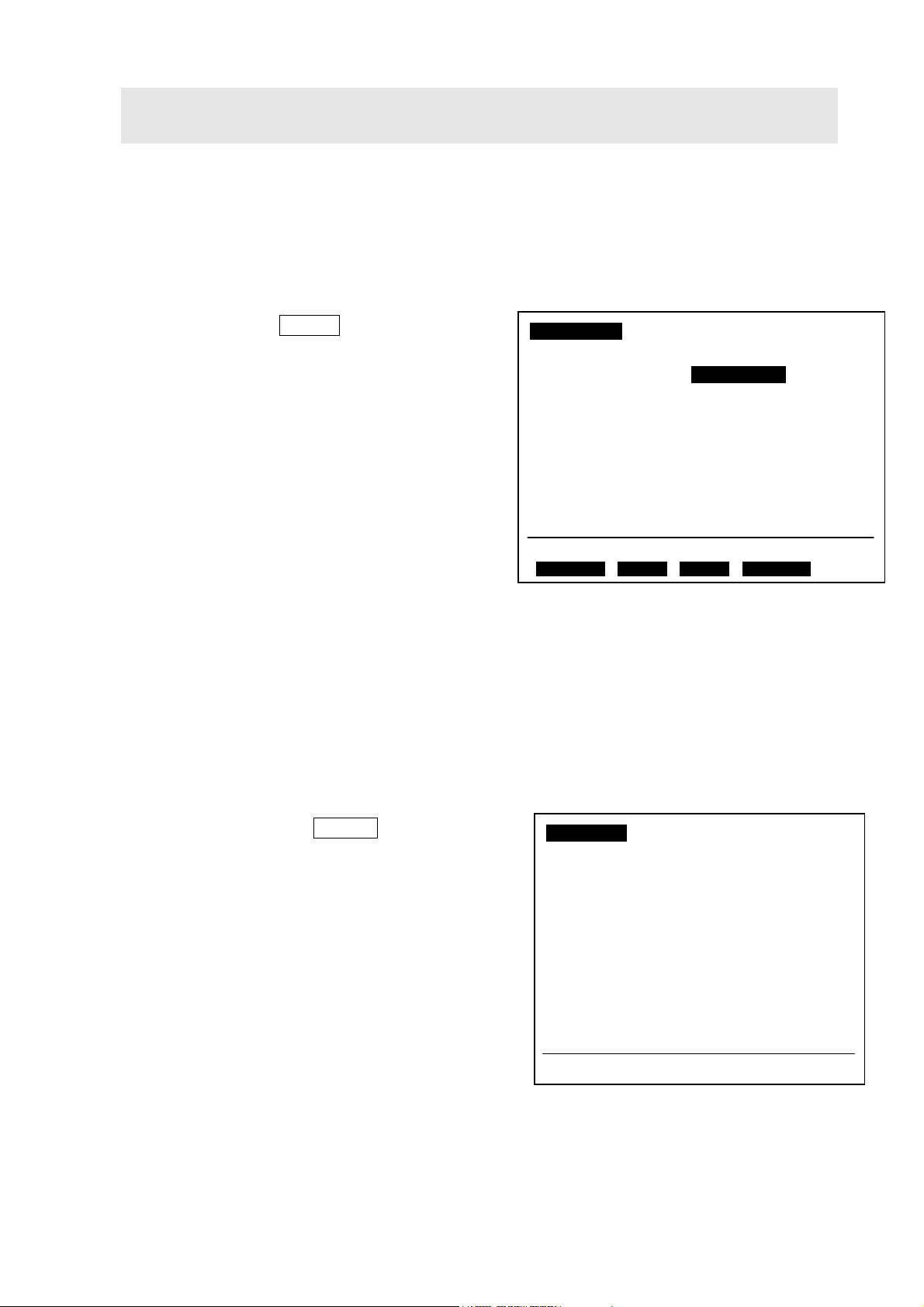
2) Press the [F3] key Mainte. on the Mode
selection screen to display the screen on the
left.
3) Press the [2] key to execute instrument
baseline correction.
4) Instrument baseline correction requires
approximately 15 minutes. Once correction
is complete, correction date and time will be
displayed in the column where previous correction date and time were located.
Note
Press the [START/STOP] key during instrument baseline correction to halt correction
Maintenance
1.Validation
2.Instrument Baseline Correction
Corrected date: 01/03/30 11:36:00
3.Lamp time used
WI Lamp: 200hours
D2 Lamp: 120hours
Input item No.
Fig.2-2 Maintenance screen
operation. If correction operation is halted, the “Not corrected” will be displayed in the column
where previous correction date and time were located. A problem may occur if measuring is
performed with instrument baseline correction in the halted status. Be sure to rerun
instrument baseline correction after resolving problems whenever this operation is halted for
whatever reason.
2-6

Chapter 3
Performance Checks
This chapter explains how to check basic performance of the
UV-1700. Note that items accompanied by an asterisk (*) require
checking as part of the acceptance procedures.
3.1 Notes on the Performance Checks
3.2 How to Use Instrument Validation
3.3 ROM Check*
3.4 Wavelength Accuracy*
3.5 Wavelength Repeatability
3.6 Resolution
3.7 Baseline Stability
3.8 Baseline Flatness*
3.9 Noise Level*
3.10 Photometric Accuracy
3.11 Photometric repeatability
3.12 Stray Light
3-1

3.1 Note on the Performance Checks
3.1.1 About ROM Check
Activating the instrument while holding down the [F1] key sets the instrument validation
measuring parameters and pass criteria values to the default settings, which are different
to the normal parameters.
3.1.2 Checking of Baseline Stability
To implement baseline stability inspection, the instrument power supply must be turned
ON for at least one hour prior to inspection. A warning message will be displayed if one
hour has not elapsed from when the power was turned ON.
3.1.3 Checking of Baseline Flatness
To implement baseline flatness inspection, the instrument power supply must be turned
ON for at least one hour prior to inspection. A warning message will be displayed if one
hour has not elapsed from when the power was turned ON.
3-2
3.2 How to Use Instrument Validation
p
Use the instrument validation functions installed in the UV-1700 to check basic performance.
This item explains how these functions are used.
3.2.1 How to Enter Instrument Validation Mode
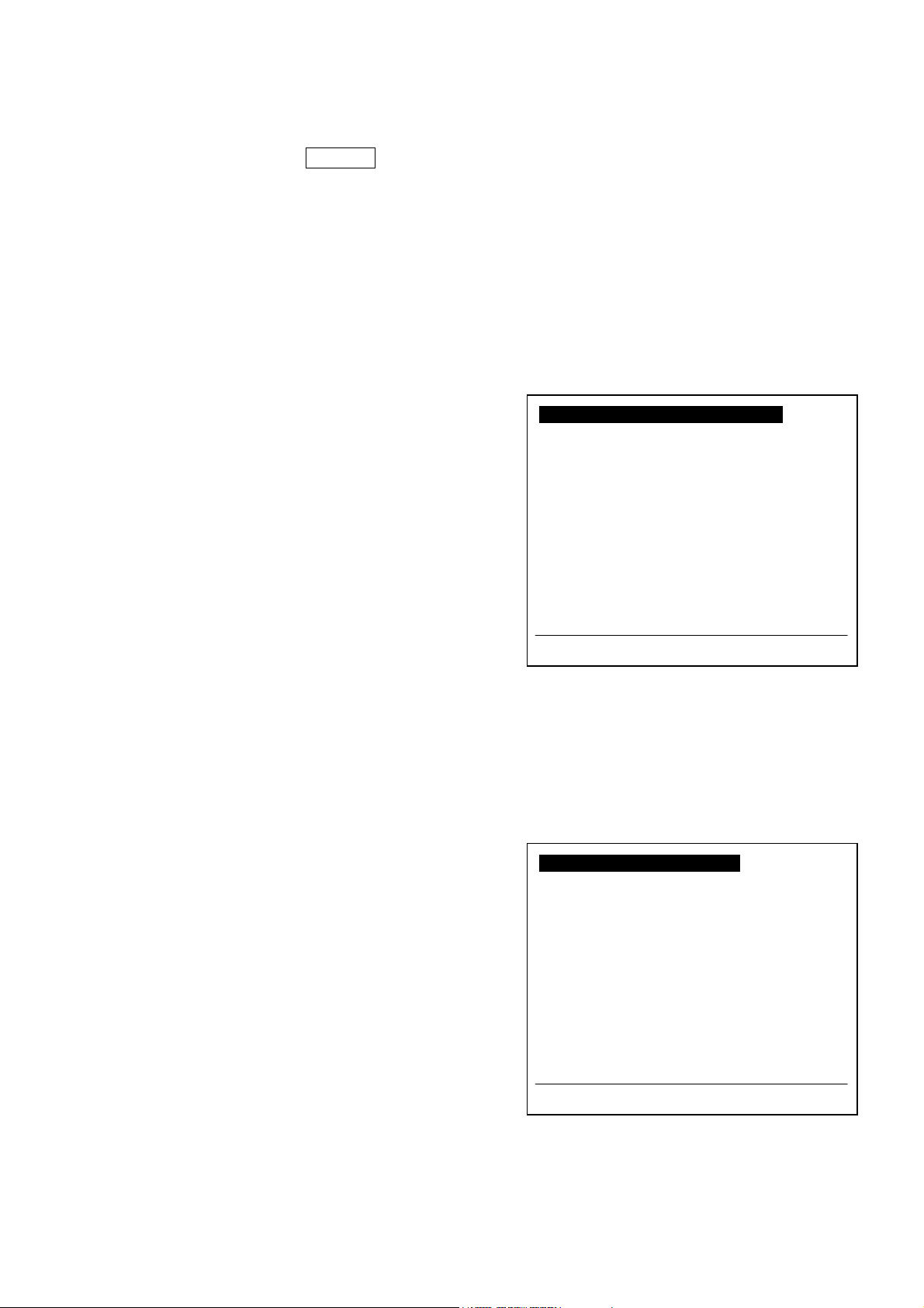
1) Press [F3] key Mainte. at the mode selection
screen to display the Maintenance screen.
Next, select “1. Validation” to display the
validation screen.
2) The check item selected for implementation
is highlighted. For example, wavelength
accuracy (WL Accuracy) is highlighted for
implementation in figure 3-1.
3) Press the [START] key to execute inspection
of the highlighted item.
4) There are two types of check available:
“Semi-Auto items” and “Auto items”.
Semi-automatic inspection is divided into items that require manual tasks such as filter
changing. Automatic inspection is divided into items that the instrument automatically
checks without any need for manual tasks.
Validation
1.Semi-Auto items 2.Auto items
PhotoAccuracy WL Accuracy
PhotoRepeatability WL Repeatability
Stray Light Resolution
Baseline Stability
Baseline Flatness
Noise Level
Init. Record
Input item No. ( To start: [START] )
PrintOut Settings
Fig.3-1 Instrument validation screen
3.2.2 Inspection Settings
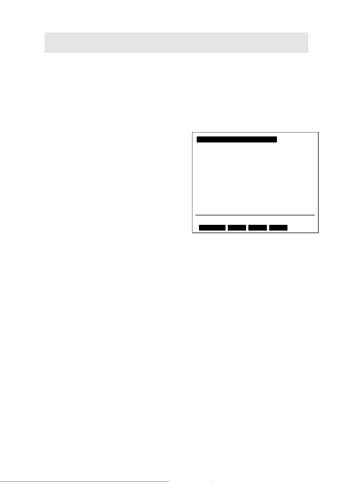
1) Press the [F4] key Settings at the instrument
validation screen to display the settings screen
for inspections.
2) Press the [1] key to enable input of password.
A password can be input in instrument
validation to prevent unauthorized changing of
validation parameters.
3) Press the [2] key to switch auto print ON and
OFF. If auto print is set to ON, inspection
results and data will be automatically printed
out when validation inspection items are
implemented. Set this to ON for performance
checks.
3-3
Settings
1.Changing a Password
2.
Auto print: OFF
In
ut item No.
Fig.3-2 Inspection settings screen
3.2.3 Printout
p
Press the [F1] key PrintOut to printout the inspection results just obtained. Inspection
results are stored in backup memory, so they will be saved even if the power is turned OFF.
Note, however, that the printout function does not printout graph data such as spectrum
and time course. To printout inspection results containing such graph data, set auto print
to ON at the inspection settings menu (see item 3.2.2), and actually implement the
inspections.
3.2.4 Semi-Auto Validations
1) Press the [1] key at the instrument validation
screen (see Fig. 3-1). Now select “1. Semi-auto
items”, the password screen will appear, so
input the password (just press the [ENTER]
key if a password is not required). The
"Settings of Semi-Auto items" screen will be
displayed.
2) Select one of the items (1 to 3) to enter the
parameter settings screen for that inspection
item. Setting changes to “Inspection: Ye s/No”,
inspection parameters and pass criteria
values can be made here (see inspection items
for details).
3.2.5 Auto Validations
1) Press the [2] key in the instrument validation
menu (see Fig. 3-1). Now select “2. Auto
items”, the password screen will appear, so
input the password (just press the [ENTER]
key if a password is not required). The
Settings of Auto items screen will be
displayed.
Settings of Semi-Auto items
1.Photometric Accuracy
2.Photometric Repeatability
3.Stray Light
In
ut item No. to change parameters.
Fig.3-3 Semi-auto inspection parameter
Settings of Auto items
1.Wavelength Accuracy
2.Wavelength Repeatability
3.Resolution
4.Baseline Stability
5.Baseline Flatness
6.Noise Level
7.Initialization Record
Input item No. to change parameters.
settings screen
3-4
Fig.3-4 Auto inspection parameter settings
screen

2) Select one of the items (1 to 7) to enter the parameter settings screen for that inspection
item. Setting changes to “Inspection: Yes/No”, inspection parameters and pass criteria
values can be made here (see inspection items for details).
Note
A password can be eliminated, when the administrator of UV-1700 forgets the password and
does not put into the condition setting screen of Semi-Auto items / Auto items. Please perform
“4.Data init. after battery change” from “3.Condition set” in the maintenance mode. However,
since the following information stored in backup RAM will also be eliminated if “4.Data init.
after battery change” is performed. Please be sure to acquire recognition of the administrator
in advance.
* Instrument baseline correction data
* Measurement data memorized in file No.0 - 5
* Measurement parameter file memorized in No.1 - 14
3-5

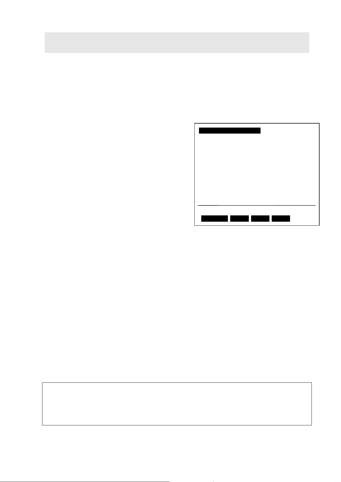
3.3 ROM Check
Specification: Latest checksum value
[Checking Method]
1) Hold down the [F1] key and turn ON the
power. Release the key once the buzzer
beeps.
2) Initialization starts and the initialization
menu will be displayed on the LCD.
3) The ROM checksum values will be displayed
to the right of the ROM Check items. Check
that they are the latest checksum values.
4) Press the [F1] key when initialization is
complete to display the mode selection
screen.
Initialization : Pass
LSI Initialize : 0
ROM Check : 30957
RAM Check : 0
Filter Origin : 0
Light Source Org.: 0
λ Org. (coarse) : 19185
W Lamp Energy : 21032
λ Org. (fine) : 64928
D2 Lamp Energy : 21913
λ Check : 6956
Ver. 1.10
Fig.3-5 Initialization setting screen
Note
Activating the instrument while holding down the [F1] key sets the instrument validation
measuring parameters and pass criteria values to the default settings, which are different to
the normal parameters.
[Checksum Value]
UV-1700 Japanese UV-1700 English
Ver. No. Checksum
1.10 16422 From 2001/3 1.10 31765 From 2001/3
1.20 15720 From 2001/6 1.20 30957 From 2001/6
Implementation period
Ver. No. Checksum
Implementation period
3-6

3.4 Wavelength Accuracy
In the case of the UV-1700, wavelength accuracy can be checked with the following two
methods.
a) Method employing a D
b) Method employing wavelength correction filter
Use method a) to check wavelength accuracy at time of installation.
Note that at time of shipping, wavelength is corrected using the Holmium oxide solution
filter (NIST SRM2034, P/N 220-92917-01).This item explains the wavelength accuracy
checking method using the Holmium oxide solution filter.
lamp line (656.1nm, 486.0nm)
2
3.4.1 Method Employing a D2 Lamp Line
Specification: Within ±
[Checking Method]
1) Press the [1] key at the auto items screen to
display the wavelength accuracy parameter
settings screen.
2) Set the parameters to match those shown in
figure 3-6.
Inspection
Each press of the [1] key selects (Yes) or
deselects (No) the inspection. Set inspection
to the "Yes” item.
Method
Press the [2] key to open an interactive
0.3nm
Wavelength accuracy
1.Inspection: Yes
2.Method: D2 Lamp
3.Check λ(nm): 486.0nm, 656.1nm
4.Tolerance: ± 0.3 nm
Input item No.
Recomnd
Fig. 3-6 Wavelength accuracy parameter
settings screen 1
screen that enables selection of either “D2 Lamp” or “Filter”. Select “D2 Lamp”.
Check λ
The wavelength changes depending on settings for inspection method. When “D2 Lamp”
is selected as the inspection method, the “486.0nm”, “656.1nm” or “Both” items can be
selected by pressing the [3] key. Select the “Both” item.
Tolerance
Press the [4] key to enable input of pass criteria value. Input range is 0.1 to 0.9. Input
“0.3”.
3-7

Recommended Value
The pass criteria value can be set to a recommended value. Do not use this item at this
point.
3) Press the [RETURN] key twice to return to the instrument validation screen. Now press
the [START] key to implement inspection followed by printout of results.
4) Check that wavelength accuracy is within
Note
With instrument validation, set inspection items will be automatically implemented in order.
Setting (selecting “Yes” for) all of the parameters in the three items (“3.4 Wavelength
Accuracy”, “3.8 Baseline Flatness” and “3.9 Noise Level”) in the acceptance procedures at time
of installation makes inspections more convenient.
±0.3nm.
3.4.2 Method Employing Holmium Oxide Solution Filter
Specification: Within
Jig: Holmium oxide solution filter (NIST SRM2034, P/N 220-92917-01)
The Holmium oxide solution filter (NIST SRM2034, P/N 220-92917-01) is also used to check
wavelength accuracy in addition to the Hg and D2 lamps at time of shipping of the UV-1700.
±0.5nm ( For NIST SRM2034)
This explanation is for the Holmium oxide solution filter.
Note
There are numerous Holmium oxide solution filters other than NIST SRM2034 that are used to
correct the wavelength of the UV-1700. Validation accuracy varies depending on the type of
Holmium filter used. Be sure to take into consideration the validation value accuracy of the
filter being used.
* The validation value accuracy for NIST SRM2034 is ±0.1nm.
* Wavelength accuracy specification for NIST SRM2034( Within ±0.5nm) includes the error of
peak pick function(±0.1nm).
[Checking Method]
1) Press the [1] key at the auto items screen to display the wavelength accuracy parameter
settings screen.
2) Set the parameters to match those shown in figure 3-7.
3-8

Inspection
Each press of the [1] key selects (Yes) or
deselects (No) the inspection. Set
inspection to the "Yes” item.
Method
Press the [2] key to open an interactive
screen that enables selection of either “D2
Lamp” or “Filter”. Select “Filter”.
Check λ
The wavelength changes depending on
settings for inspection method. When
“Filter” is selected as the inspection
Wavelength accuracy
1.Inspection: Yes
2.Method: Filter
3.Check λ(nm):
640.5 536.6 485.3 467.8 416.3
385.7 361.3 345.5 333.4 287.2
278.1 249.9 241.1 0.0 0.0
4.Tolerance: ± 0.5 nm
5.Filter
S/N; 12345678 GOOD THRU; 01/03/30
Input item No.
Recomnd
Fig. 3-7 Wavelength accuracy parameter
settings screen 2
method, enter the wavelength in order by
pressing the [3] key. Enter "0" and press the [ENTER] key to complete entry.
Tolerance
Press the [4] key to enable input of pass criteria value. Input range is 0.1 to 0.9. Input
the “0.5” value. ( ±0.5nm includes the accuracy of NIST SRM2034(±0.1nm) and the
accuracy of peak pick function(±0.1nm). )
Filter
Input the serial number (S/N) and expiration date for the correction filter to be used. A
filter that has passed the expiration date cannot be used for an inspection.
Recommended Value
The pass criteria value can be set to a recommended value. Do not use this item at this
point.
3) Press the [RETURN] key twice to return to the instrument validation screen. Now press
the [START] key to implement inspection followed by printout of results.
4) Check that wavelength accuracy is within
±0.5nm.
3-9
3.5 Wavelength Repeatability
This checks wavelength repeatability by measuring the D
lamp line (656.1nm, 486.0nm)
2
three times, and verifying the deviation between the average value and each individual
measuring value.
Specification: Within
±0.1nm
[Checking Method]
1) Press the [2] key at the auto items screen to
display the wavelength repeatability
parameter settings screen.
2) Set the parameters to match those shown in
figure 3-8.
Inspection
Each press of the [1] key selects (Yes) or
deselects (No) the inspection. Set inspection
Wavelength repeatability
1.Inspection: Yes
2.Tolerance: Ave. ± 0.1 nm
Input item No.
Recomnd
to the "Yes” item.
Tolerance
Press the [2] key to enable input of pass
Fig.3-8 Wavelength repeatability parameter
settings screen
criteria value. Input range is 0.1 to 0.9. Input “0.1”.
Recommended Value
The pass criteria value can be set to a recommended value. Do not use this item at this
point.
3) Press the [RETURN] key twice to return to the instrument validation screen. Now press
the [START] key to implement inspection followed by printout of results.
4) Check that wavelength repeatability is within
±0.1nm.
3-10

3.6 Resolution
This measures the 656.1nm line of the D
lamp, takes the peak half height width of the
2
spectrum waveform, defines it as a resolution and checks that value.
Specification: 1.0nm or less
[Checking Method]
1) Press the [3] key at the auto items screen to
display the resolution parameter settings
screen.
2) Set the parameters to match those shown in
figure 3-9.
Inspection
Each press of the [1] key selects (Yes) or
deselects (No) the inspection. Set
inspection to the "Yes” item.
Tolerance
Resolution
1.Inspection: Yes
2.Tolerance: 1.0 nm or less
Input item No.
Recomnd
Fig.3-9 Resolution parameter settings screen
Press the [2] key to enable input of pass
criteria value. Input range is 0.1 to 9.9. Input “1.0”.
Recommended Value
The pass criteria value can be set to a recommended value. Do not use this item at this
point.
3) Press the [RETURN] key twice to return to the instrument validation screen. Now press
the [START] key to implement inspection followed by printout of results.
4) Check that wavelength accuracy is within
±0.1nm.
3-11
3.7 Baseline Stability
This measures the time variation in the vicinity of zero absorption (0Abs) for the specified
wavelength, and checks the hourly rate of variation.
Specification: Within 1.0mAbs/h ( @700nm )
[Checking Method]
1) Press the [4] key at the auto items screen to
display the baseline stability parameter
settings screen.
2) Set the parameters to match those shown in
figure 3-10.
Inspection
Each press of the [1] key selects (Yes) or
deselects (No) the inspection. Set inspection
to the "Yes” item.
Check λ
Press the [2] key to enable input of
wavelength to be measured for time
variation. Input “700.0”.
Tolerance
Press the [3] key to enable input of pass criteria value. Input range is 0.0 to 99.9. Input the
“1.0” value.
Baseline Stability
1.Inspection: Yes
2.Check λ: 700.0 nm
3.Tolerance: 1.0 mABS/H
Input item No.
Recomnd
Fig.3-10 Baseline stability parameter settings
screen
Recommended Value
The pass criteria value can be set to a recommended value. Do not use this item at this
point.
3) Press the [RETURN] key twice to return to the instrument validation screen. Now press
the [START] key to implement inspection followed by printout of results.
4) Check that baseline stability is within 1.0mAbs/h.
Note
To implement baseline stability inspection, the instrument power supply must be turned ON
for at least one hour prior to inspection. A warning message will be displayed if one hour has
not elapsed from when the power was turned ON.
3-12
3.8 Baseline Flatness
This corrects the baseline to a blank status at both the sample (S) and reference (R) sides of
the sample compartment, measures the spectrum, and uses the amount of curve to check
baseline flatness.
Specification: Within
[Checking Method]
1) Press the [5] key at the auto items screen to
display the baseline flatness parameter
settings screen.
2) Set the parameters to match those shown in
figure 3-11.
Inspection
Each press of the [1] key selects (Yes) or
deselects (No) the inspection. Set inspection
to the "Yes” item.
Scanning Range
Press the [2] key to enable input of the
wavelength scanning range to be measured
for the spectrum measurement. Set to the “1100.0nm to 190.0nm” range.
±2mAbs (note that shock noise should be within 4mAbs)
Baseline flatness
1.Inspection: Yes
2.Scanning Range: 1100.0 ~ 190.0 nm
3.Tolerance: ± 2 mABS
Input item No.
Recomnd
Fig.3-11 Baseline flatness parameter settings
screen
Tolerance
Press the [3] key to enable input of pass criteria value. Input range is 1 to 99. Input the
“2” value.
Recommended Value
The pass criteria value can be set to a recommended value. Do not use this item at this
point.
3) Press the [RETURN] key twice to return to the instrument validation screen. Now press
the [START] key to implement inspection followed by printout of results.
4) Check that baseline flatness is within
shock noise is within 4mAbs.
* Shock noise easily occurs at the following stray light cut filter switching wavelengths and
light source switching wavelengths: 760nm, 536nm, 416nm, 365nm, 305nm, 340.8nm.
±2mAbs. Also, visually check spectrum to see that
3-13

Note
To implement baseline flatness inspection, the instrument power supply must be turned ON
for at least one hour prior to inspection. A warning message will be displayed if one hour has
not elapsed from when the power was turned ON.
3-14
3.9 Noise Level
This measures for one minute the time variation in the vicinity of zero absorption (0Abs) for
the specified wavelength, and checks the P-P noise from that amplitude. It also calculates
the RMS value from the one-minute data.
Specification: P-P Within 2mAbs (same for each wavelength)
RMS 0.2mAbs or less (@700nm)
0.3mAbs or less (@500nm)
0.4mAbs or less (@250nm)
[Checking Method]
1) Press the [6] key at the auto items screen to
display the noise level parameter settings
screen.
2) Set the parameters to match those shown in
figure 3-12.
Inspection
Each press of the [1] key selects (Yes) or
deselects (No) the inspection. Set inspection
to the "Yes” item.
Check λ
Press the [2] key to enable input of
wavelength to be measured for time
variation. Input “700.0”.
Tolerance
Press the [3] key to enable input of pass criteria value. Input range is 0.0 to 99.9. Input
“2” as the P-P value and “0.2” as the RMS value.
Noise level
1.Inspection: Yes
2.Check λ: 700.0 nm
3.Tolerance: P-P 2.0 mABS or less
RMS 0.2 mABS or less
Input item No.
Recomnd
Fig.3-12 Noise level parameter settings
screen
Recommended Value
The pass criteria value can be set to a recommended value. Do not use this item at this
point.
3) Press the [RETURN] key twice to return to the instrument validation screen. Now press
the [START] key to implement inspection followed by printout of results.
4) Set the inspection wavelength to 500nm and the RMS value of the pass criteria to within
0.3mAbs. And inspect the noise level.
3-15

5) Set the inspection wavelength to 250nm and the RMS value of the pass criteria value to
within 0.4mAbs. And inspect the noise level.
6) Check that each inspection result conforms to the specification.
3-16

3.10 Photometric Accuracy
This measures the optic filter for transmittance correction, checks the deviation against the
validation value and makes the result the photometric accuracy.
Check photometric accuracy using the semi-automatic inspection item in the instrument
validation functions.
Specification: Within
Within
Jig: NIST substandard filter (P/N 755-03576)
CPS-240A (P/N 204-05837-01)
[Pre-inspection Preparation]
Bring the NIST substandard filter to a constant temperature.
1) Turn ON the power for the CPS-240A. Set temperature to 23.5°C.
2) Set the NIST substandard filter in the cell holder of the CPS-240A. Maintain the filter at
a constant temperature.
Cell position 1: None
Cell position 2: 10%T (vicinity of 1Abs) filter
Cell position 3: 30%T (vicinity of 0.5Abs) filter
Note
The NIST substandard filter must be maintained at 23.5°C during inspection because the
measuring value varies with the temperature of the filter.
±0.002Abs (vicinity of 0.5Abs)
±0.004Abs (vicinity of 1.0Abs)
[Checking Method]
1) Press the [1] key at the semi-auto items
screen to display the photometric accuracy
parameter settings screen.
2) Set the parameters using those shown in
figure 3-13 as reference.
3-17
Photometric accuracy
1.Inspection: Yes
2.Meas. mode: Abs
3.Check λ(nm):
635.0/ 590.0/ 546.1/ 465.0/ 440.0
4.10% Filter: S/N; 12345678
Good THRU; 01/03/30 Tolerance; ±4mAbs
5.30% Filter: S/N; 87654321
Good THRU; 01/03/30 Tolerance; ±2mAbs
Input item No.
Recomnd
Fig.3-13 Photometric accuracy parameter
settings screen
 Loading...