

Page 1
S321-78282
Aug. 2019
Top-loading Balance
UPX Series
UP223X, UP423X, UP623X, UP823X, UP1023X
UP422X, UP822X
UP2202X, UP4202X, UP6202X
UP4201X, UP8201X
UPY Series
UP223Y, UP423Y, UP623Y, UP823Y, UP1023Y
UP422Y, UP822Y
UP2202Y, UP4202Y, UP6202Y
UP4201Y, UP8201Y
Instruction Manual
Read the instruction manual thoroughly before you use the product.
Keep this instruction manual for future reference.
Foreword
Name and Function
1.
of Components
2. Installation
3. Basic Operation
4.
Menu Item Selection
5.
Built-in Clock Set-up
6. Display Selection
7. Calibration
8. Environment
9.
Unit Display Set-up
Enhancing
10.
Productivity
UP0000x
3
UP0000x3UP0000x
3
Application
11.
Functions
Connections and
Communications with
12.
External Equipment
Maintenance and
13.
Transportation
14.
Troubleshooting
Appendices
Page 2

No text
Page 3
Foreword
Read the instruction manual thoroughly before using the product.
Thank you for purchasing the Shimadzu Top-loading Balance UP Series.
This instruction manual provides details on how to use the balance and on the accessories and options,
etc., that are related to it. Read the manual thoroughly and make sure it is used in accordance with the
details listed herein. The following instruction manual is also supplied with this product.
Simple Sheet: Operation Guide 321-78282 Operation descriptions in a simple diagram format.
Store the instruction manuals together with the product in an easily-accessible location.
The instruction manuals (PDF format) can also be downloaded from the Shimadzu website
(https://www.an.shimadzu.co.jp/balance/)
Balances
Notices
• If the balance is to be operated by a different user or transferred to a different location, make sure the
instruction manuals are also provided to the subsequent users.
• Contact the Shimadzu sales office or agency in the event of the instruction manuals were lost or
mislaid.
• Safety precautions are listed in the instruction manual to ensure safe usage. Read the section on
[Safety Precautions] thoroughly prior to using the balance.
• You are requested to complete the user registration procedure to ensure that your balance can be
used without anxiety. This is required when making claims against the product warranty, and you are
requested to complete either of the following two user registration procedures.
(1) Fill in the details on the rear of the [Product Warranty] card provided, and send it to us by facsimile.
(2) Access our website and will in the details accordingly.
(https://www.an.shimadzu.co.jp/balance/user/index.html)
SEARCH
Click
Once you have completed the user registration procedures, you will be given precedence with
regard to receiving information on product warranty and Shimadzu products and services.
(You are also requested to fill in the questionnaire.)
Notices
• The content of this manual is subject, without notice, to modifications for the sake of improvement.
• Every effort has been made to ensure that the content of this manual was correct at the time
of creation. However, in the event that any mistakes or omissions are discovered, it may not be
possible to correct them immediately.
• The copyright of this manual is owned by Shimadzu Corporation. Reproduction and duplication of
whole or part of the content without permission of the company are strictly prohibited.
• Windows is the registered trademark of Microsoft Corporation of the U.S.A. in the United States
and other countries. All other company names and product names that appear in this manual are
trademarks or registered trademarks of the companies concerned. Note that ™ and ® indications
are not used.
• UniBloc and Smart+ are the registered trademarks of Shimadzu Corporation in Japan.
• Shimadzu does not guarantee that the serial communication functions will operate without problem
on all PCs. Shimadzu will not accept responsibility for any trouble that arises as a result of using this
function. It is recommended that all important data and programs are backed up in advance.
© 2019 Shimadzu Corporation. All rights reserved.
I
Page 4
Foreword
Notation Conventions Used within the Instruction Manual
The instruction manual uses the following notation conventions in accordance with the degree of risk and
damage to equipment.
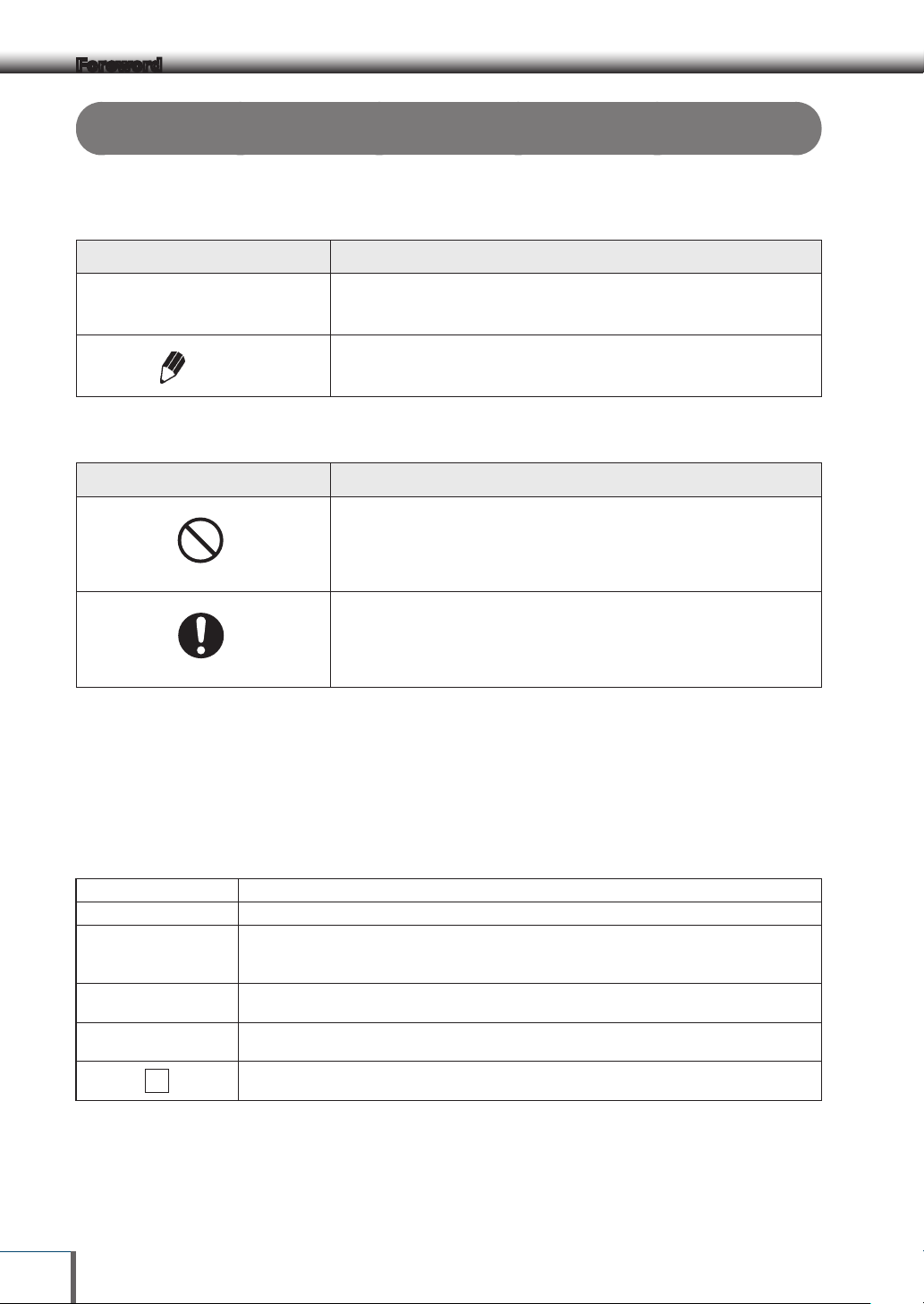
Notation Description
!
Caution
Indicates a potentially hazardous situation which, if not avoided,
may result in minor to moderate injury or equipment damage.
Provides additional information needed to properly use the
Note
balance.
Descriptions of the other pictograms used within the instruction manual are listed below.
Pictogram Description
Indicates an action that must NOT be performed
Prohibitions
Indicates an action that must be performed.
Instructions
The functions available for use and the selectable items differ in accordance with the model with the UP
Series. Read the sections concerning the model in use.
Other conventions used in this manual include:
1, 2, 3, … Indicates the step number in a procedure
[POWER] key Indicates the operation key on the balance.
Items displayed on the balance display are shown in [ ] brackets.
[E-CAL ] etc...
mass display
Mass display
1
This also includes displayed items when selecting a menu item and is also used to identify
menu items.
Indicates that the balance is in the weighing mode and mass is displayed in one of the
weighing units.
Indicates that the balance display is in one of the mass units and that the value displayed will
change according to the load on the pan.
Indicates the menu item to be selected.
In the number of the menu item on the Menu Map. See A-2 “Menu Map”.
II
Page 5
UP Series
The UP Series comprises of the Top-loading equilibrium balances mounted with aluminum UniBloc sensors. This
instruction manual provides details on operating the UP Series models listed below. The functions available differ
in accordance with the model, so check the product label located on the front or back of the balance and read the
sections concerning the model in use.
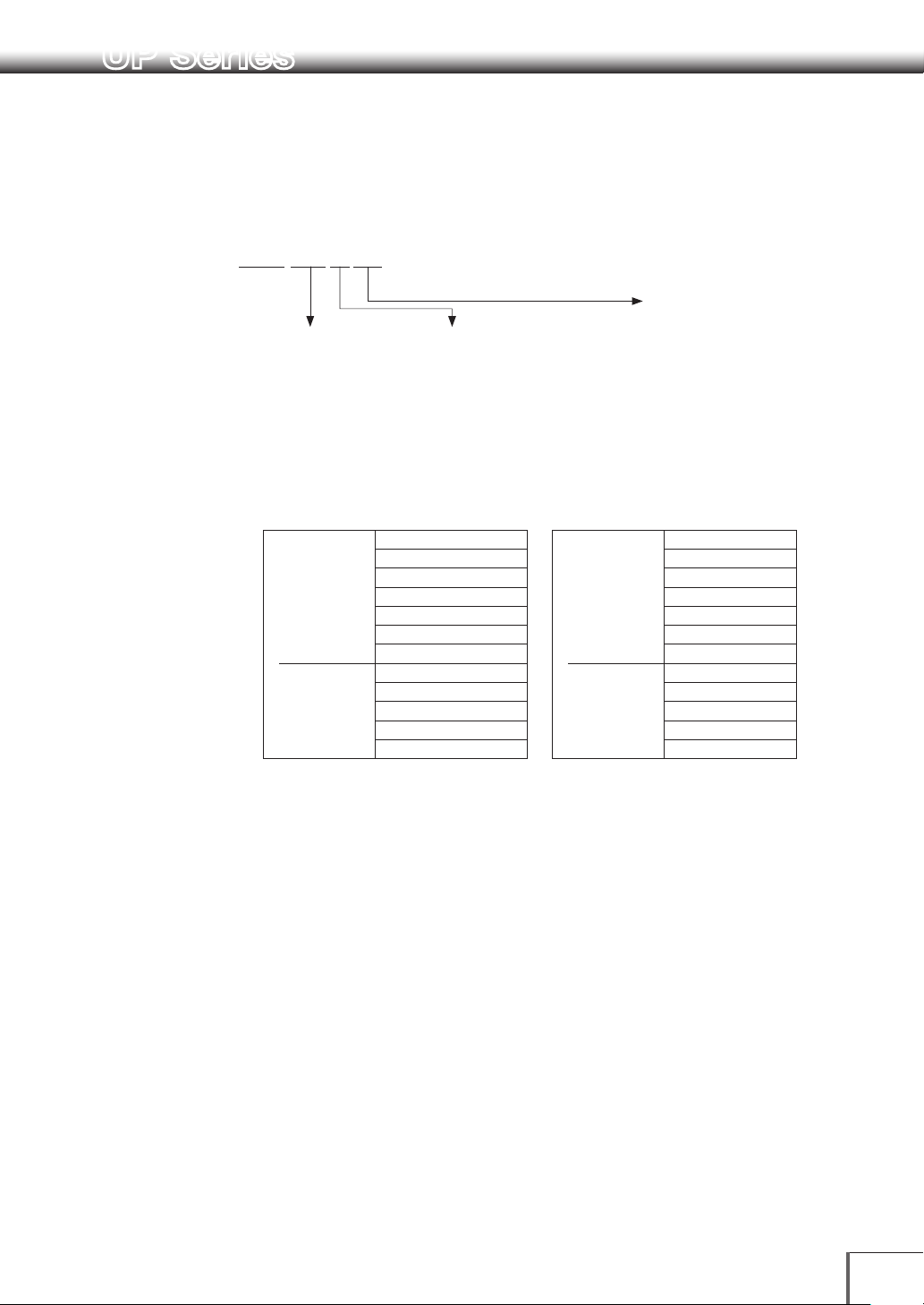
About the model name
Example:
UP Lineup
UP223X
Model
name
Capacity
22: 220g
42: 420g
62: 620g
82: 820g
102: 10 20 g
220: 2200 g
420: 4200 g
620: 6200 g
820: 8200g
UPX Series UP223X UPY Series UP223Y
Small pan type
Large pan typ e
Minimum display
1: 0.1 g
2: 0.01 g
3: 0.001 g
UP423 X
UP623X UP623Y
UP823X UP823Y
UP10 23X UP10 23Y
UP422X U P422Y
UP822X UP822Y
UP2202X
UP4202X UP420 2Y
UP6202X UP6202Y
UP42 01X UP4201Y
UP8 201X UP 820 1Y
Small pan type
Large pan typ e
Series name
X : X Series (with built-in
calibration weight)
Y : Y Series
UP423Y
UP2202Y
For information on the following points, please contact your Shimadzu Balance representative.
• Product warranty
• After service
III
Page 6
Prohibitions
Prohibitions
Safety Precautions
Precautions on Use
To be strictly observed
To ensure that you use the balance safely and correctly, read the following precautions carefully. The details listed
below provide important information on safety, and must be observed at all times.
Precautions Related to Usage
■
CAUTION
!
Prohibitions
Cannot be used as proof of transactions.
The balance is not permitted by law to be used as proof of transaction for drug formulation, etc.
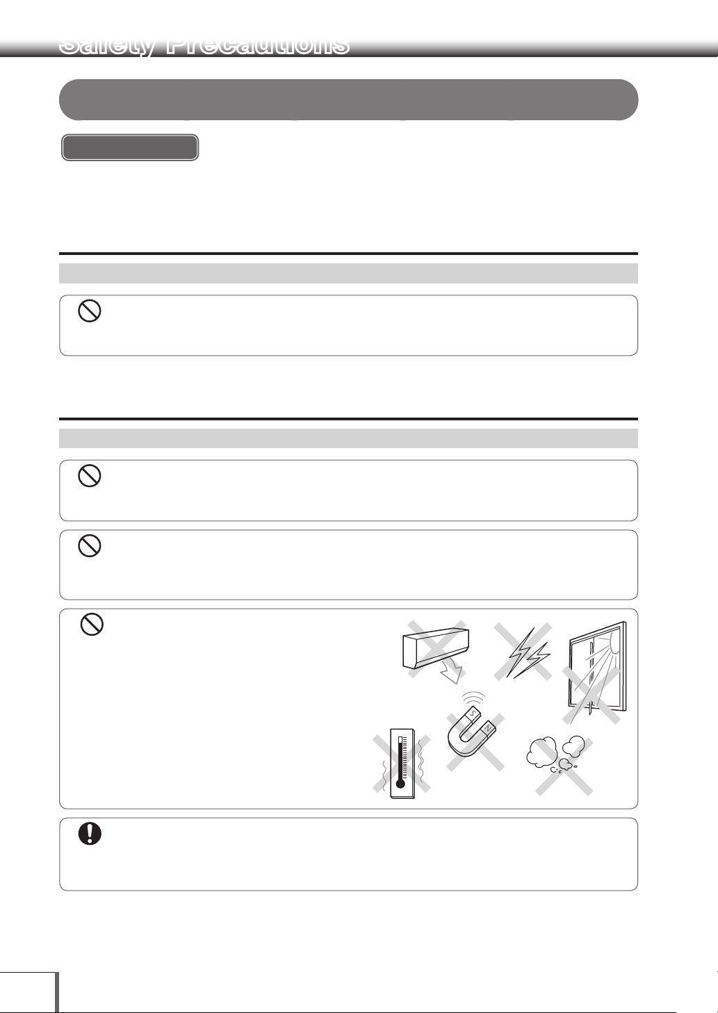
Precautions Related to Place of Installation
■
CAUTION
!
Do not use the balance outdoors or anywhere where it will be exposed to water.
You could sustain an electric shock or the product could operate abnormally.
Prohibitions
Avoid locations where the balance will be exposed to volatile gas, flammable
gas or corrosive gas.
Failure to observe this may result in the outbreak of fire and accidents.
Avoid locations where the balance will
be exposed to any of the following.
This could cause accidents or poor performance.
• Air flow from an air conditioner, ventilator, door or
window
• Extreme temperature changes
• Vibration
• Direct sunlight
• Dust, electromagnetic waves or a magnetic field
• Condensation
IV
Instructions
Install the balance on a strong and stable flat table or floor.
Placing the balance in an unstable site could lead to injury or trouble with the balance. When selecting the
installation site, take into account the combined weight of the balance and the item to be weighed.
Page 7
Safety Precautions
Prohibitions
Instructions
Instructions
Precautions Related to Installation Work
■
CAUTION
!
Do not connect anything other than peripheral devices specified by Shimadzu to the balance’s connector.
If you do, the balance may stop working normally. In order to avoid trouble, always connect peripheral devices
in accordance with the directions in this manual.
Instructions
Instructions
Instructions
Use the correct power supply and voltage with the AC adapter supplied.
Using the balance with an incorrect power supply or voltage may result in the outbreak of fire or malfunctions. Note also that if the power supply
or voltage is unstable or if the power supply capacity is insuf ficient, it will not be possible to obtain satisfactory performance from the balance.
The included AC adapter is for use with this product only.
Do not use the included AC adapter with any other devices. Doing so could cause fires or other damage.
Install measures to prevent the balance from toppling over in the event of earthquakes, etc.
If the balance topples over as a direct result of vibrations, it may result in injury.
Plug the AC adapter into an easily accessible power outlet.
During emergencies, it is necessar y to unplug the AC adapter from the power outlet.
Instructions
Beware of the gaps between equipment during installation.
Failure to observe this may result in fingers getting caught, leading to injury. Place fingers on the indentations
on the sides of the unit and grip it firmly with both hands during installation.
Precautions Related to Work/Operations
■
CAUTION
!
Use the correct weighing units.
Using incorrect weighing units can lead to accidents as a result of weighing errors. Check that the weighing
units are correct before starting weighing.
Instructions
Prohibitions
Treat the balance with care and respect.
The balance is a precision instrument. Subjecting it to impact may result in malfunctions. When moving the balance, remove the pan,
the pan supporter the shield plate, fix the glass draft shield, the Draf t shield inner plate, the Power pack, the Stage, the Shield case
and the Multi-stand, etc in place, and grasp it firmly with both hands when carrying it. If the balance is to be stored for long periods of
time, place it in the packaging box which was used for delivery and store it in a safe location with few temperature fluctuations.
Risks Involved in Repairs/Dismantling/Modifications
■
CAUTION
!
Never disassemble, modify or attempt to repair this product or any accessory.
You could sustain an electric shock or the product could operate abnormally. If you believe that the balance
has failed, contact your Shimadzu representative.
V
Page 8
Safety Precautions
Instructions
Precautions Related to Inspections/Maintenance
■
CAUTION
!
Prohibitions
The design standard period of usage for this product is ten years. Using
the product for more than the design standard period may result in it being
impossible to maintain performance or malfunctions, etc.
• A fee is charged for safety inspections. Direct all requests to our sales offices, dealers or the service
agencies specified by the company.
• The design standard period is the standard period during which the product can be used safely without
malfunctions, and it does not represent the valid period of product warranty.
• See [Chapter 13. Maintenance and Transportation] for details on daily maintenance inspections and
replacement parts.
Instructions
Instructions
Unplug the power cord from the AC adapter during inspections, maintenance and
when replacing parts.
Failure to observe this may result in accidents caused by electric shocks or shor t-circuits.
Always use the parts specified in the instruction manual when replacing parts.
The use of non-specified parts may result in them becoming damaged and unusable.
Measures to be Observed during Emergencies
■
CAUTION
!
If you detect anything abnormal (e.g. a burning smell), immediately disconnect the
AC adapter from the power outlet.
Continuing to use the balance with an abnormality could lead to fire or an electric shock.
Measures to be Observed during Power Outages
■
CAUTION
!
Instructions
VI
After a power outage, turn the power back ON.
When a power outage occurs, the power is shut off automatically. Therefore, begin operation from “Turning on
the Power” (P.15) again.
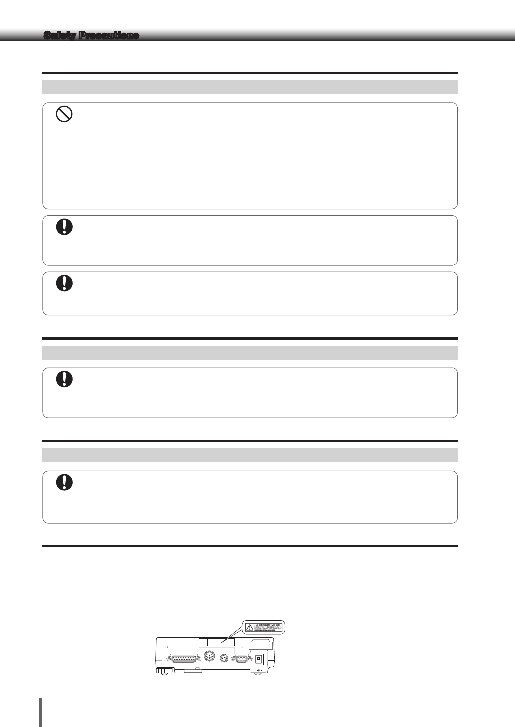
Caution Labels
■
Cautions labels are placed in necessary locations on the balance to ensure that it is used correctly. In the event of
these labels being mislaid or damaged, contact a Shimadzu sales office or service agency to request new labels,
and then make sure they are situated in the correct locations.
[UP223X example]
Use the AC adapter supplied
with the specified power supply
DATA I/ORS232C AUX KEY
DC IN
Page 9
Safety Precautions
Residual Risk Information
■
Residual risk refers to the risks that could not be removed or reduced during the design and manufacturing stages.
Check the [Residual Risk Maps] for each area with inherent risks and implement protective measures while
referring to the [List of Residual Risks].
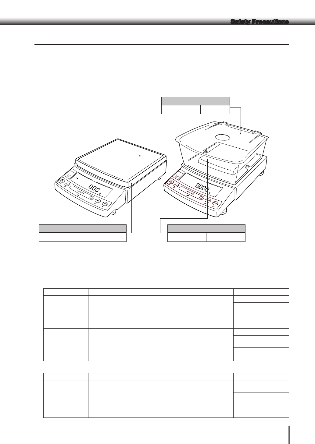
■ Residual Risk Maps
The [Equipment Location] and [No.] shown below match up with the [List of Residual Risks].
Refer to the [List of Residual Risks] for further details.
Location A: Windbreak set
! Caution
No.1
UP0000x
3
Location C: Large pan windbreak
! Caution
No.2
UP0000x3UP0000x
3
Location B: Pan
! Caution
No.3
■ List of Residual Risks
The [No.] and [Equipment Location] shown below match up with the [Residual Risk Maps].
Check the [Residual List Maps] for fur ther retains on the relevant [Equipment Location].
Read and fully comprehend the details listed in [Refer To] and implement protective measures without fail.
Measurement Preparations
No.
Equipment Location
1 A
If you attempt to move the
balance while holding the
windbreak set, the windbreak
will detach from the balance.
2 C
When setting the large pan
windbreak, holding it by the
corners could cause you to cut
your hands.
Risk
! Caution
! Caution
Protective Measures Implemented by Users
When moving the balance, do not hold
the windbreak set, instead securely hold
the main body from the bottom using
both hands.
When installing the windbreak, do not
hold it by sharp edges when placing.
— —
Re f er To
Task Moving the
Qualifications
& Training
Re f er To
Task Windbreak
Qualifications
& Training
P10
Balance
Recipients of
Work Training
P12
installation
Recipients of
Work Training
Maintenance
No.
Equipment Location
3 A
Risk
! Caution
Transporting the balance with
the pan and pan supporter
installed could result in damage
to the main body.
Protective Measures Implemented by Users
Always remove the pan and pan
supporter when transporting the
balance for repair.
— —
Refer ToP10
Task Transporting
during repairs
Qualifications
Recipients of
& Training
Work Training
VII
Page 10

Safety Precautions
Product Warranty
Shimadzu provides warranty with regard to the following as a basic principle. See the [Product Warranty]
supplied for further details.
1. Period of Warranty
Valid for one year from the date of purchase. (Restricted to Japan).
2. Items Covered by the Warranty
Malfunctions attributable to Shimadzu occurring within the period of warranty will be repaired or parts
replaced free of charge. (The warranty is only valid within Japan).
3. Limitation of Liability
1) Shimadzu cannot be held responsible for the users’ loss of profit, indirect damages or secondary damages
under any circumstances. The company can also not be held responsible for damages relating to damage
compensation caused to users by third parties.
2) The liability for compensatory damages attributable to Shimadzu is limited to a sum equivalent to the cost of
the product in all cases.
4. Warranty Exemption
The warranty is not valid for malfunctions attributable to the following, even during the period of warranty.
1) Malfunctions occurring as a result of misuse.
2) When the product is repaired or modified, etc., by any company or person other than Shimadzu Corporation.
3) Malfunctions attributable to causes other than the product itself.
4) When used in harsh environments, such as high-temperature and high-humidity environments, environments
subject to corrosive gases, and environments subject to vibrations, etc.
5) Malfunctions caused by fire, earthquakes or other natural disasters, by contamination caused by radioactivity
or toxic substances, or by unavoidable situations, such as war, civil unrest and crime.
6) When moved or transported elsewhere after having been installed.
7) Consumable parts and parts conforming to this designation.
VIII
Page 11

Safety Precautions
Aftercare Services and Part Supply Period
1. Aftercare Service
In the event of the product not operating normally, carry out inspections and resolve the problem in
accordance with the instructions providing in [14.Errors and Recovery] ( P.91). If the problem persists or
other problems that are thought to be malfunctions not covered by the instructions provided arise, contact
the numbers provided on the back cover.
2. Part Supply Period
The period during which replacement parts will be supply for the product is up until seven years after the
termination of manufacture.
Note that there are cases in which it will not be possible to supply replacement parts once this supply
period has elapsed. However, the supply periods stipulated separately by the manufacturers will be
applied for parts not manufactured by Shimadzu.
Inspections and Maintenance
Daily inspections, Periodic inspections and regular calibrations are required to ensure that the
performance of the balance is maintained for long periods of time so that correct measurement data can
be acquired.
• See [Chapter 13. Maintenance/Inspections] for details on daily inspections and part replacement.
• Contact a Shimadzu sales office or service agency, or one of Shimadzu’s service companies to request
Periodic inspections and regular calibrations.
Product Disposal
When disposing of the product, dismantle and dispose of the parts separately in accordance with their
composition in order in consideration of environmental conservation.
Direct all inquiries to the contact numbers provided on the back cover.
IX
Page 12
Safety Precautions
Safety Precautions
Shimadzu Balances and 21 CFR Part 11
21 CFR Part 11
21 CFR Part 11, Electronic Records, Electronic Signatures, Final Rule (often referred to as Part 11) is the
United States Food and Drug Administration (FDA) regulation affecting computer resources and electronic
records that are used for any document that is required to be kept and maintained by FDA regulations.
Requirements concerning computer resources security are key elements in Part 11.
The controls implemented as a result of security related requirements are intended to result in trusted
records.
Shimadzu Lab Solutions Balance
Shimadzu provides a means for compliance with 21 CFR Part 11 with Shimadzu Lab Solutions Balance
software, part of a comprehensive laboratory data management system, Shimadzu Lab Solutions.
Ask your Shimadzu representative about it.
Two-way Communication
Shimadzu balances have always been computer friendly and they can be set up for bi-directional
communication as part of a fully automated production system or LIMS.
This manual includes the command codes and information needed by programmers to integrate
Shimadzu balances with their software.
Action for Environment (WEEE)
To all user of Shimadzu equipment in the European Union:
Equipment marked with this symbol indicates that it was sold on or after 13th August 2005,
which means it should not be disposed of with general household waste. Note that our equipment is for
industrial/professional use only.
Contact Shimadzu service representative when the equipment has reached the end of its life.
They will advise you regarding the equipment take-back.
With your co-operation we are aiming to reduce contamination from waste
electronic and electrical equipment and preserve natural resource through
re-use and recycling.
Do not hesitate to ask Shimadzu service representative, if you require further
information.
For Caifornia, USA Only
This product contains a battery that contains perchlorate material.
Perchlorate Material - special handling may apply.
See www.dtsc.ca.gov/hazardouswaste/perchlorate
WEEE Mark
X
Page 13

Table of Contents
Foreword.......................................................I
UP Series .................................................... III
Safety Precautions .....................................IV
Precautions on Use ............................................ IV
■ Precautions Related to Usage .........................IV
■ Precautions Related to Place of Installation ..... IV
■ Precautions Related to Installation Work ..........V
■ Precautions Related to Work/Operations ......... V
■
Risks Involved in Repairs/Dismantling/
Modifications ..............................................V
■ Precautions Related to Inspections/
Maintenance ...........................................VI
■ Measures to be Observed during
Emergencies .......................................... VI
■ Measures to be Observed during Power
Outages .................................................. VI
■ Caution Labels ................................................ VI
■ Residual Risk Information ............................... VII
Aftercare Services and Part Supply Period .......... IX
Inspections and Maintenance ..............................IX
Product Disposal ................................................. IX
Shimadzu Balances and 21 CFR Part 11 ..............X
Action for Environment (WEEE) ............................. X
Table of Contents .......................................XI
1. Name and Function of Components .. 1
1.1 Components ............................................ 1
1.2 Key Panel and Operation ......................... 3
1.3 Balance Display and Function .................. 4
2. Installation ........................................... 5
2.1 Choosing the Installation Site ................... 5
2.2 Unpacking and Delivery Inspection .......... 7
2.3 Installation .............................................. 10
2.4 Turning on the Power ............................. 15
2.5 Span Calibration .................................... 16
3. Basic Operation The balance can
be used correctly according to the
content of Chapters 1 to 4 ................ 19
3.1 Weighing ................................................ 19
3.2 Changing the Unit Display ...................... 20
4. Menu Item Selection (Read Chapters
4 to 12 before using the balance) ..... 21
4.1 What is the Menu? ................................. 21
4.2 Menu Map .............................................. 21
4.3 Menu Item Selection Procedure ............. 22
4.4 Setting Numeric Values .......................... 25
4.5 Related Useful Functions .......................26
4.5.1 Last Menu Recall....................... 26
4.5.2 Returning to the Default Settings
(menu reset) .............................. 26
4.5.3 Menu Lock ................................ 27
5. Built-in Clock Set-up ......................... 28
5.1 Da t e ....................................................... 28
5.2 Date Output Style .................................. 28
5.3 Time ....................................................... 29
5.4 Setting Display During Stand-by ............ 29
6. Display Selection ..............................30
6.1 Bar graph display ................................... 30
6.2 Changing the Minimum Display Digit .....30
7. Calibration ......................................... 31
7.1 What is calibration? ................................ 31
7.2 Calibration Execution ............................. 32
7.2.1 Span Calibration Using the Built-in
Weight (UPX Series Only) .......... 32
7.2.2 Calibration Check Using the Built-
in Weight (UPX Series Only) ....... 33
7.2.3 Span Calibration Using External
Weights ..................................... 35
7.2.4 Calibration Check Using External
Weights ..................................... 36
7.3 Calibration Setting .................................. 37
7.3.1 Selecting the Calibration Type ... 37
7.3.2 PSC Fully-automatic Calibration
(UPX Series only) ....................... 37
7.3.3 Clock-CAL Fully-automatic
Calibration (UPX Series only) ..... 39
7.3.4 PCAL: Calibration of the Built-in
Weight (UPX Series only) ........... 40
7.3.5 PCAL Password Setting (UPX
Series only) ................................ 41
7.4 Maintaining Calibration Reports… GLP/
GMP/ISO Compliant Measurement
Management Systems ........................... 42
7.4.1 Calibration Report Setting ......... 42
7.4.2 Balance ID Setting ..................... 42
8. Environment ......................................43
8.1 O v e r v ie w ................................................ 43
8.2 Stability and Response (Averaging) ........ 43
8.3 Stability Detection and Settings ............. 45
8.3.1 Stability Detection Band ............ 45
XI
Page 14

Table of Contents
8.3.2 Timing of Stability Mark
Illumination and Data Output .....46
8.4 Tracking ................................................. 46
9. Unit Display Set-up ........................... 47
9.1 Units .......................................................47
9.2 Percentage (%) Conversion .................... 48
10. Enhancing Productivity .................... 49
10.1 Checkweighing and Target Display ........ 49
10.1.1 Checkweighing (Comparator)
Display Type 1 ........................... 50
10.1.2 Checkweighing (Comparator)
Display Type 2 ........................... 50
10.1.3 Target Mode .............................. 51
10.2 Piece Counting (PCS) ............................. 52
10.3 Automatic Printing and Output
(Auto Print) .............................................53
10.4 Automatic Compensation of Zero Point
Drift (Auto Zero) ...................................... 55
10.5 Sample Loading and Unloading
Determination (Zero Range) ...................56
10.6 Taring/Printing at Stability ...................... 57
10.7 Registering Container Weight (Pretaring
Value) ..................................................... 58
11. Application Functions ....................... 59
11.1 Solid Specific Gravity Measurement ...... 59
11.2 Liquid Density Measurement .................62
11.3 Detecting Peak Values (Peak Hold) ........ 65
11.4
Outputting at Fixed Times (Interval Timer) ....... 67
11.5 Measuring a Large Number of Small
Samples (Add-on Mode) ........................68
11.6 Animal Weighing mode .......................... 70
11.7 Formulation Mode .................................. 73
12.5.3 Format ....................................... 88
12.5.4 Communication Speed .............88
12.5.5 Parity / Bit Length ..................... 88
12.5.6 Stop Bit ..................................... 89
12.5.7 Delimiter .................................... 89
12.6 Decimal Point Symbol in Output Data .... 89
13. Maintenance and Transportation ..... 90
13.1 Maintenance ..........................................90
13.2 Moving the Balance ............................... 90
14. Troubleshooting ................................ 91
14.1 General Display ...................................... 91
14.2 Error Display .......................................... 92
14.3 Troubleshooting .....................................93
14.4 LCD (Liquid Crystal Display) Check ........ 93
Appendices ...............................................94
A-1. Specifications ........................................ 94
A-2. Menu Map .............................................. 96
A-3. Standard Accessories and Maintenance
Parts List .............................................. 101
A-4. Optional Accessories List..................... 102
A-5. RS-232C/Specifications of Connectors 10 3
A-6. Unit Conversion Coefficient List ........... 104
A-7. Performance Checks ........................... 105
A-8. Below-Weigh Hook Dimensions ........... 10 6
A-9. Index .................................................... 107
12. Connections and Communications
with External Equipment .................. 75
12.1 Connecting Printers ...............................75
12.2 Connecting Personal Computers ........... 76
12.3 Connecting PLCs and Other Serial
Communications Equipment .................. 78
12.4 Cable Connections (RS232C) ................79
12.4.1 Connecting the Cable ...............79
12.4.2 Data Format .............................. 80
12.4.3 Using Command Codes ............82
12.5 Communication Setting ......................... 87
12.5.1 Overview ................................... 87
12.5.2 Handshaking ............................. 87
XII
Page 15
Large pan windbreak
Labe
Sh
an
re
w
we
us
Operatio
Used
an
inpu
Adjust to level the balance
otects against
Label
Shows model name.
"Max" and "d" ar
indications r
legal metr
not r
range in general use.
or message
Operation keys
Used to tar
and functions, pr
input numerical values
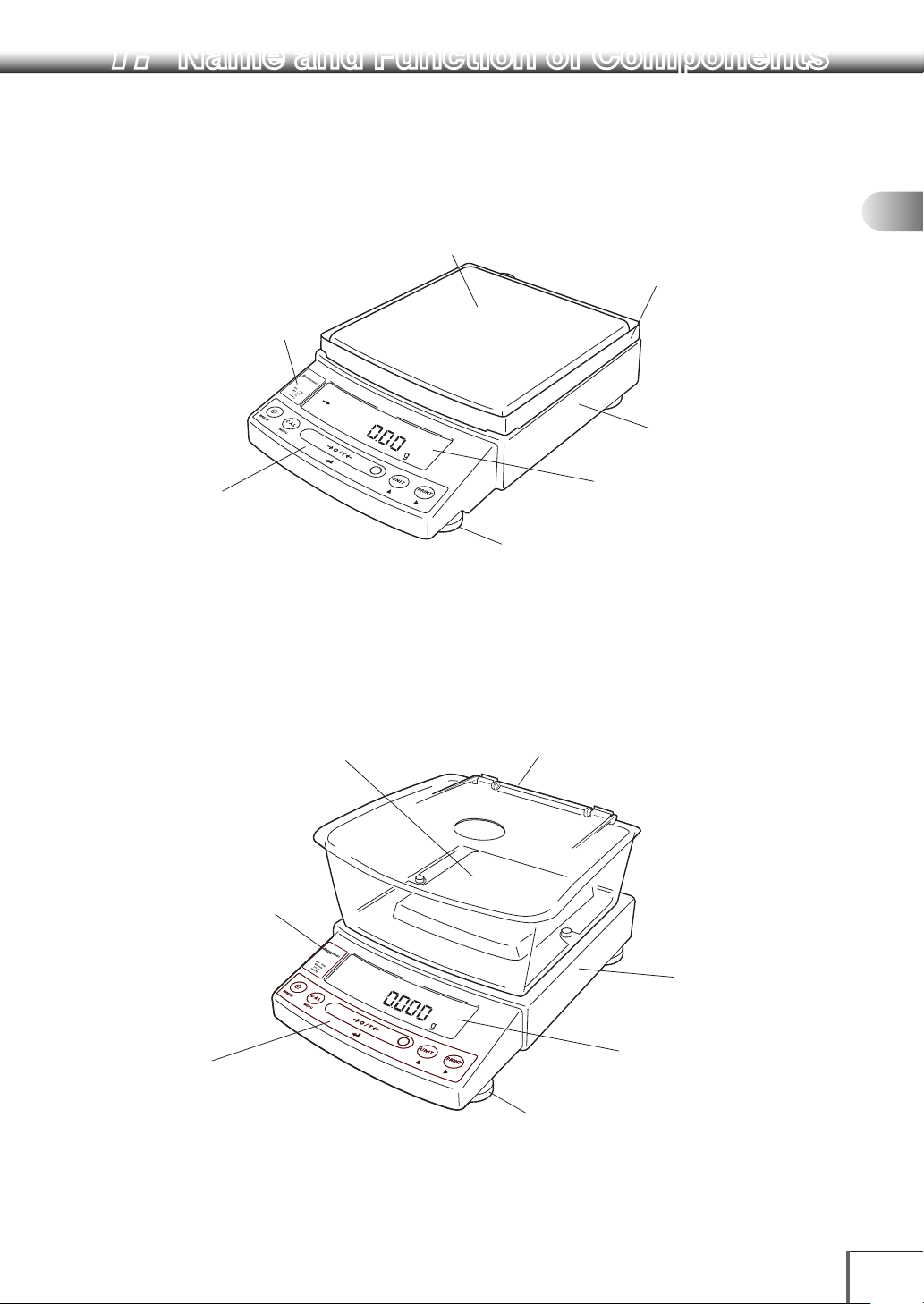
1. Name and Function of Components
1.1 Components
a. Large pan model
Even light breezes can have an effect on
Pan
l
ows model name. "Max"
d "d" are indications
quired by legal metrology,
hich do not restrict the
ighing range in general
e.
n keys
to tare, execute calibration
d functions, program functions,
t numerical values
b. Small pan model (minimum display 0.001g, windbreak standard)
Pan
Supports the object to be weighed
UP0000x
3
Supports the object to
be weighed
measurements, so the windbreak protects
against wind.
The windbreak is not included with models
with a minimum display of 0.1 g.
Main body
Display panel
Shows weighed result, information
on programming function, indicates
current setting, working function,
necessary operation, and error message
Level screws
Windbreak set
Even light breezes can have an effect on
measurements, so the windbreak pr
wind.
1
2
3
4
5
6
7
8
9
e
equired by
ology, which do
estrict the weighing
e, execute calibration
ogram functions,
10
11
UP0000x3UP0000x
3
Main body
12
13
Display panel
Shows weighed result, information
on programming function, indicates
current setting, working function,
necessary operation, and err
Level screws
Adjust to level the balance
14
1
Page 16
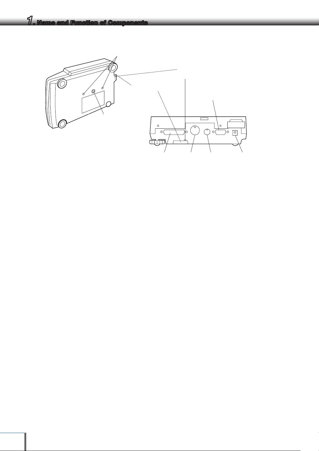
1. Name and Function of Components
RS-232C
Connector
Connector
(Connectors on the back)
KEY Connector
プ
a,b. Common
Transportation screws
(only for UPX Series)
Theft preventing ring
Below-weigh hook cap
下皿フックキャッ
Ground terminal
Connect this terminal to ground if necessary
DATA I/O
Connector
AUX
Connector
DC IN
2
Page 17
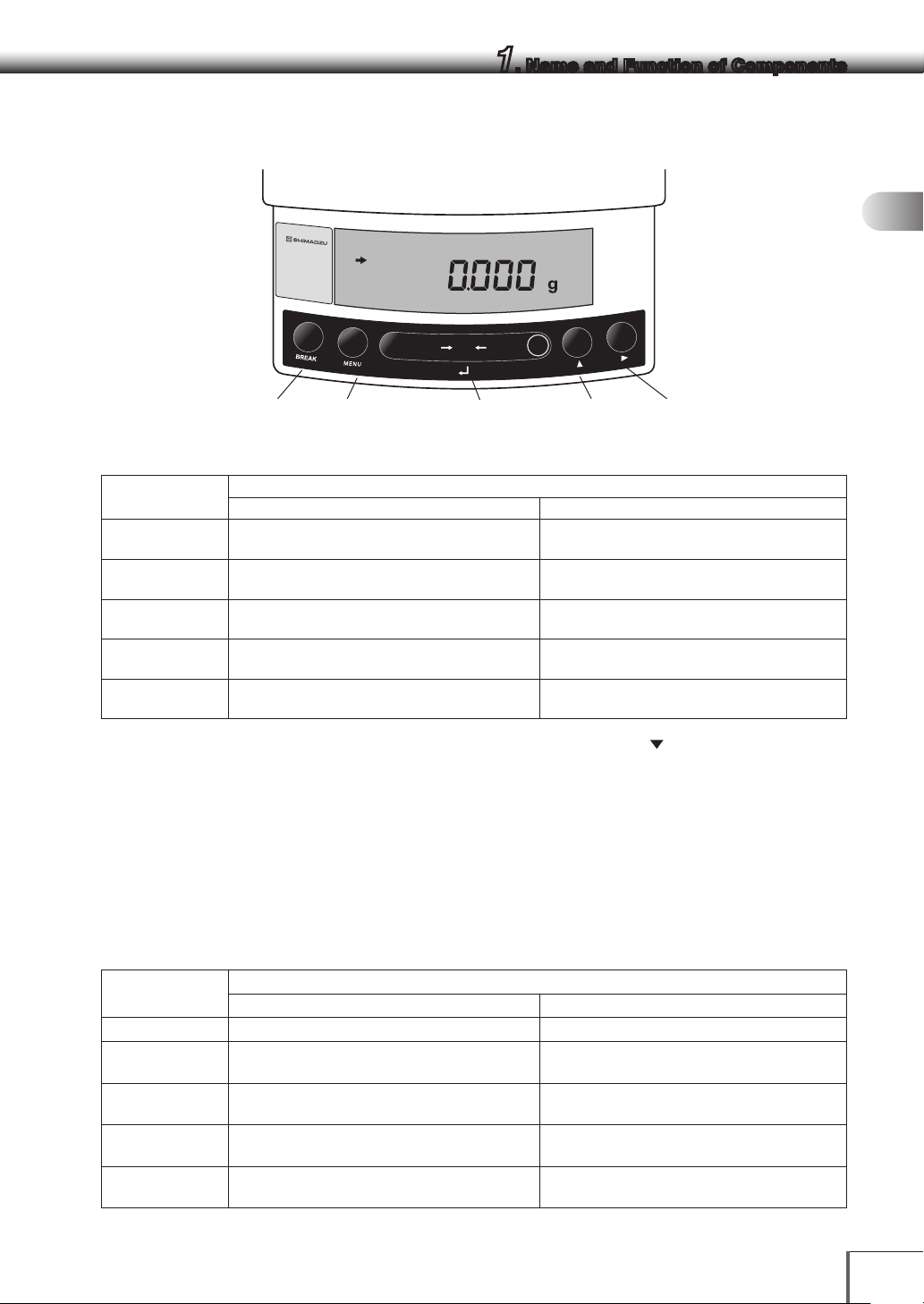
1. Name and Function of Components
1.2 Key Panel and Operation
UP1023X
Max
1020g
d= 0.001g
1
2
POWER
CAL
Functions of the keys
Key
[POWER]
[CAL]
[O/T ] Tares the balance. (Displays zero.) (*2) Displays the Pretare value. (*6)
[UNIT]
[PRINT]
*1 This key is used to set values when percent (%), number (PCS), solid specific gravity ( d), or liquid specific gravity (d)
are displayed.
*2 When a Pretare value is set, zero is not displayed and [-Pretare value] is displayed.
*3 Units other than “g” must be set up before they can be used for measurement. Only gram (g), percent (%), and piece
counting (PCS) are set-up before shipment.
*4 When the unit is set to 10d, the resolution of the minimum display is decreased by one decimal place.
*5 In Pouring mode (See 8.2), the right-most part of [O/T] key marked with a circle functions as the switch for
environmental condition setting. Otherwise this part functions the same way as the other parts of [O/T] key.
*6 Either “Taring” (at a weight exceeding 2.0% of the capacity) or “Zeroing” ( at a weight within 2.0% of the capacity)
takes place with a verified balance as a legal measuring instrument in using region.
*7 Not applicable to a verified balance as a legal measuring instrument in using region.
Switches between the operation and standby
modes.
Enters span calibration or menu item selection.
(*1)
Changes the weighing unit or selects the
specific gravity measurement. (*3)
Sends the displayed value to a peripheral
device.
Press Once and Release Press and Hold for About 3 Seconds
O / T
During Weighing
Exits the application function and returns to
the mass display.
Displays the last menu item that was set. (Last
menu recall)
Switches between the 1d and 10d displays.
(*4) (*7)
Sends the date and time to a peripheral
device. (*6)
UNIT
PRINT
[PRINT] key[CAL] key[POWER] key [UNIT ] key[O/T ] key
3
4
5
6
7
8
9
10
11
12
Key
[POWER] Returns to the previous menu level Returns to the mass display.
[CAL] Moves to the next menu item.
[O/T ]
[UNIT]
[PRINT]
Selects or sets the currently displayed menu
item, or enter into the displayed menu.
Increases the numeric value of the blinking digit
by 1.
Moves to the next digit during numeric value
en try.
Press Once and Release Press and Hold for About 3 Seconds
During Menu Item Selection
Displays the last menu item that was set. (Last
Menu Recall)
No operation.
No operation.
No operation.
13
14
3
Page 18
1. Name and Function of Components
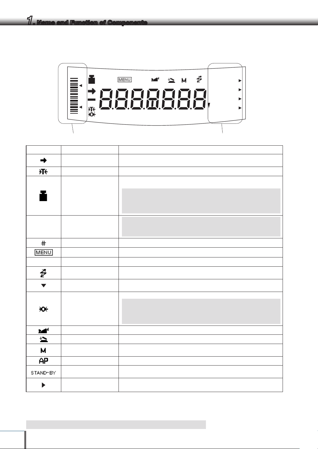
1.3 Balance Display and Function
HI
#
GO
LO
Analog display section Unit display section
Display Name Description
Stability mark
Tare symbol Indicates that a Pretare value has been set. (*3)
Weight symbol
[ ] Bracket
Number symbol Indicates numeric value entry.
Menu symbol Illuminates during menu item selection.
*
Asterisk
Communication symbol
Inverse triangle symbol
Zero symbol
BATT
AP WARM-UPSTAND-BY
Indicates that the weighed value is stable. (*1) In menu item selection, this
symbol indicates currently selected item. (*1)
Illuminates during span calibration.
Blinks before automatic span calibration starts.
Note: Using a verified balance as a legal measuring instrument in
using region:
When PSC fully-automatic span calibration is not activated, operator must
carry out span calibration with the built-in weight upon blinking of this symbol.
Note: Using a verified balance as a legal measuring instrument in
using region:
The figure bordered by the bracket is the auxiliary indicating device.
Indicates that the displayed numeric value is not a mass value. (*2)
Illuminates during communication to external equipment through the
RS-232C or DATA I/O connector.
Indicates the set-up of solid specific gravity measurement. Used as a
substitution of the decimal point.
Indicates the set-up of Auto Zero function.(*3)
Note: Using a verified balance as a legal measuring instrument in
using region:
Indicates that the balance is set exactly to "Zero" with the zero-setting
function(+/- 0.20e: e = verification scale interval).
%NETBPTG
PCS lbGN
mg mom
ctdwt
kg
oztl
Animal symbol
Add-on symbol Indicates the set-up of Add-on mode or Formulation mode.
Memory symbol
Auto Print symbol Indicates the set-up of Auto Print function.
Stand-by symbol
Response stability
setting symbol
*1 Stability mark The displayed value may change while the stability symbol remains illuminated if the load is
changing slowly or if the stability detection band has been set to a large value.
*2 Decimal replacement If there are any decimals to the right of 7 digit numbers, this will be displayed to indicate the
presence of the decimals that are not displayed.
*3 Not applicable to a verified balance as a legal measuring instrument in using region
Indicates the set-up of Animal Weighing function.(*3)
Displays when the net total mass measurement function (memory
function) is ON.
Illuminates when the balance power is in the standby mode.
Also illuminates when the application function has entered the standby mode.
Displays to indicate response stability setting status.
4
Page 19
2. Installation
2.1 Choosing the Installation Site
(1) Power supply
Select an installation site with a power source that allows for proper use of the included AC adapter.
Verify that the supply power voltage conforms to that indicated on the AC adapter.
1
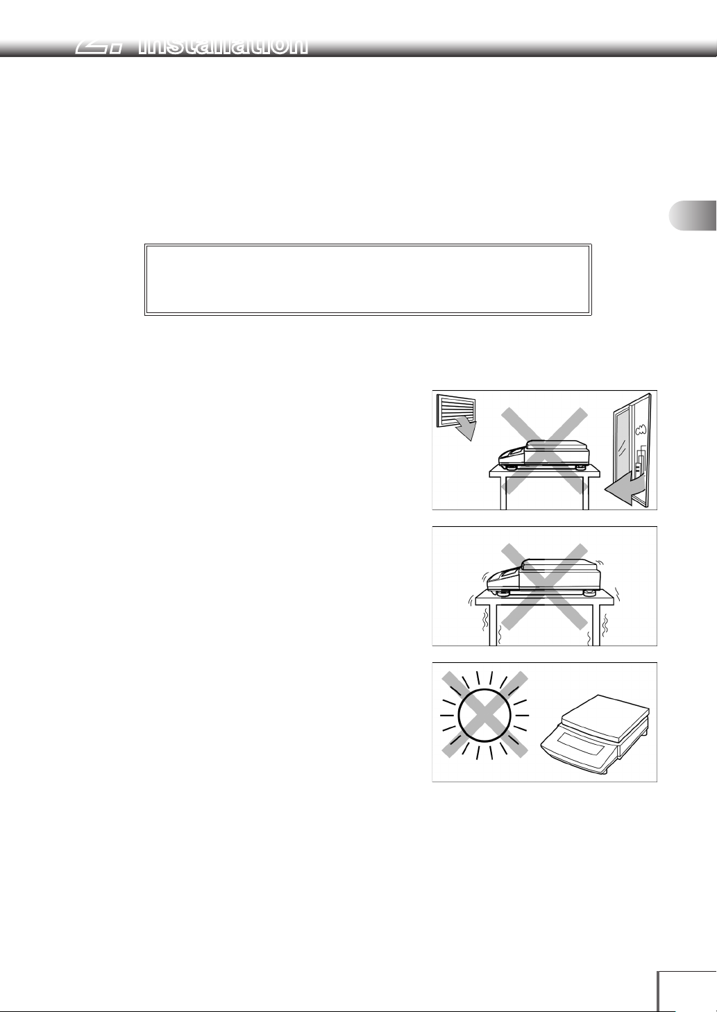
(2) Installation site
Caution
!
Avoid sites where the balance will be exposed to the following:
• Air flow from air-conditioner, open window, or ventilator
• Vibration
2
3
4
5
6
7
8
9
• Direct sunlight
10
11
12
13
Continued
14
5
Page 20
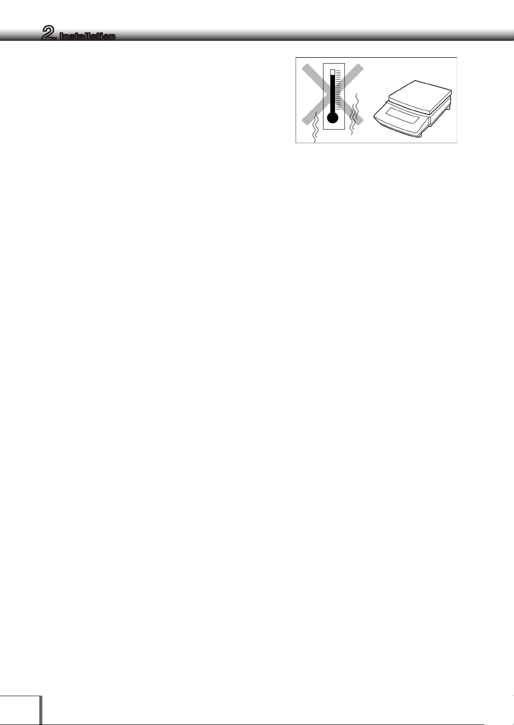
2. Installation
• Extreme temperature, temperature changes or humidity
• Corrosive or flammable gasses
• Dust, wind, electromagnetic waves, or magnetic fields
Install the balance on a strong and stable flat table or floor in the room.
Large capacity balances should be installed on a sturdy floor and table that can support the total load of
the balance and object to be weighed.
6
Page 21
2. Installation
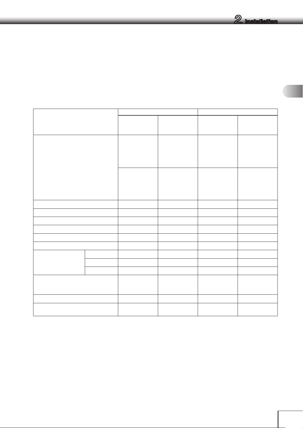
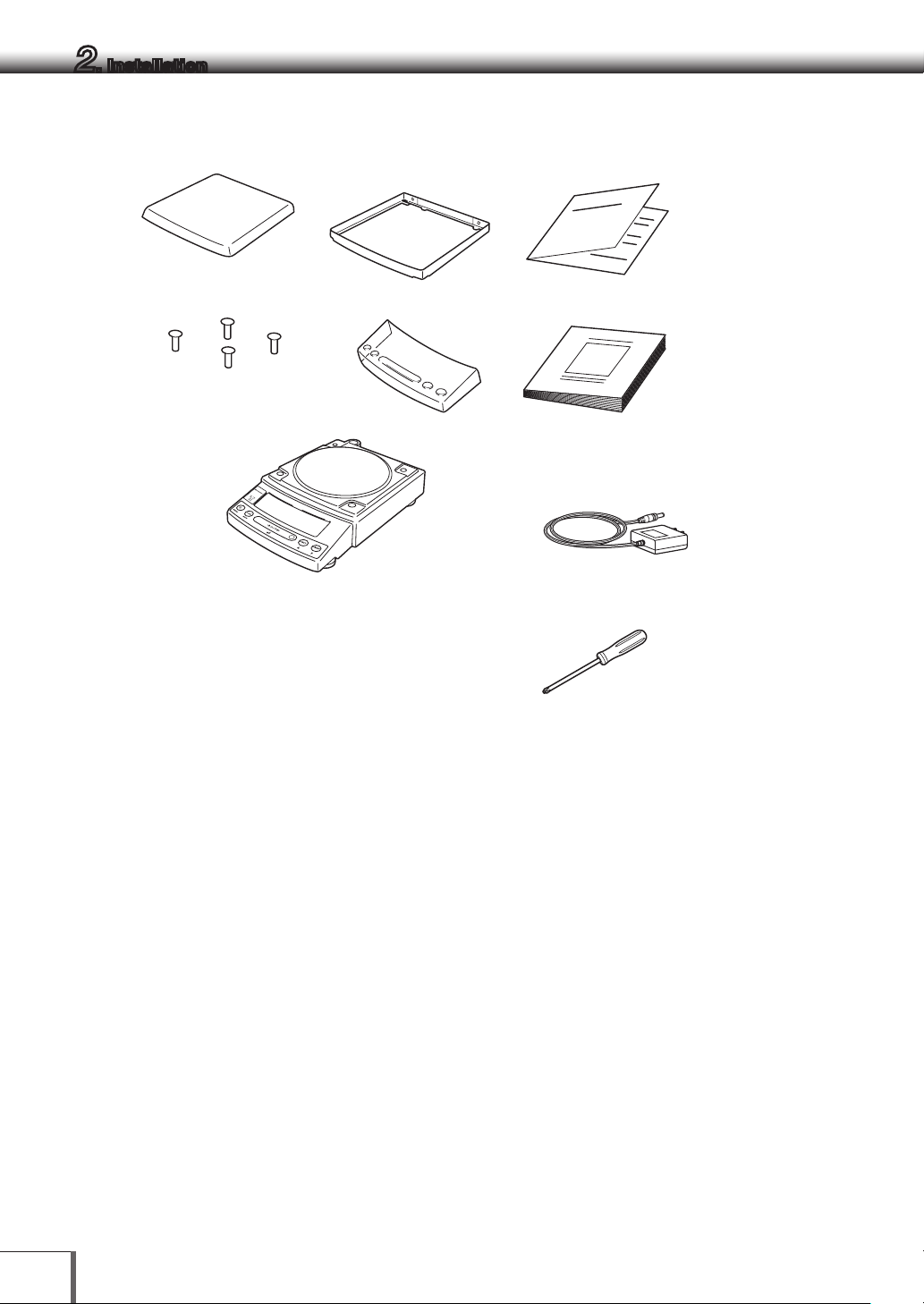
2.2 Unpacking and Delivery Inspection
Unpack and remove all the items from the delivery box. Check if all the listed items are present and
nothing has been damaged. Contact your local distributor in case of damaged or missing items. Contact
information is provided on Last page.
1 Standard packed item and quantity
1
2
a. Large pan model b. Small pan model
Typ e
Model UP4201X
Balance main body 1 1 1 1
Pan supporter cap 4 4 4 4
Pan 1 1 1 1
AC adapter 1 1 1 1
In-use protective cover 1 1 1 1
Windbreak (for Large pan) 0 1 0 0
Windbreak set (for
Small pan)
Rubber cap 0 0 2 (installed on
Stainless screw 0 0 2* 2*
Instruction manual (incl. operation
explanation sheet)
Main 0 0 0 1
Lid 0 0 0 1
Fixing knob 0 0 0 2
Minimum
display d=0.1g
UP8201X
UP4201Y
UP8201Y
1 1 1 1
Minimum
display
d= 0.01g
UP2202X
UP4202 X
UP6202X
UP2202Y
UP4202Y
UP6202Y
Minimum
display
d= 0.01g
UP422X
UP822X
UP422Y
UP822Y
balance main
body)
Minimum
display
d= 0.001g
UP223X
UP423X
UP623X
UP823X
UP1023X
UP223Y
UP423Y
UP623Y
UP823Y
UP1023Y
2 (installed on
balance main
body)
3
4
5
6
7
8
9
10
11
12
* In cases where there is any risk of organic solvents coming into contact with the main body, pull off the 2 rubber caps
from the top of the main body and fasten the included stainless steel screws in the holes.
13
14
7
Page 22
2. Installation
a. Large pan model
■Balance main body
UP0000x
3
■Large pan windbreak
(0.01 g models only)
■In-use protective cover■Pan supporter caps
■Operation explanation sheet■Pan
■Instruction manual
■AC adapter
(The shape of the adapter supplied with
the balance may differ from this gure.)
■ScrewDriver
8
Page 23
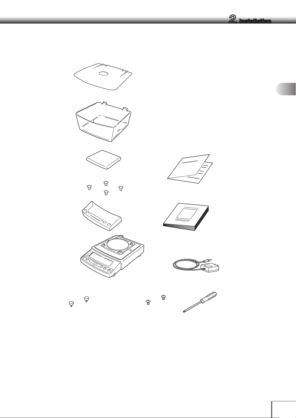
b. Small pan model
■Windbreak Lid
(minimum display0.001gmodelsonly)
2. Installation
1
■Windbreak Main
(minimum display0.001gmodelsonly)
■Pan
■Pan supporter caps
■In-use protective cover
■Balance main body
UP0000x
3
■operation explanation sheet
■Instruction manual
■AC adapter
(The shape of the adapter supplied with
the balance may differ from this figure.)
2
3
4
5
6
7
8
9
(minimum display0.001gmodelsonly)
10
■Stainless screws■Fixing knobs for windbreak
■Screw Driver
11
12
13
14
9
Page 24
2. Installation
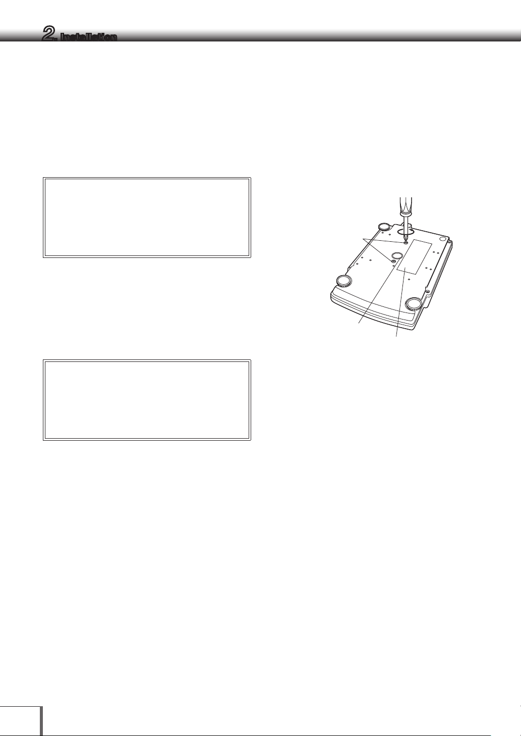
2.3 Installation
Start at step 3 when installing a UPY Series balance. Prepare a plus (+) screw driver for a UPX Series
balance.
1 Place the balance main body upside down. (UPX
only)
Caution
!
Do not operate step 2 with the balance placed
on its side. Place the balance on a smooth
surface.
2 Referring to the explanation label on the bottom
of the balance, turn the two transportation
screws counterclockwise until they tighten
again. (UPY only)
Transportation screws
(only for UPX Series)
Below-weigh
hook cap
Explanation label
(only for UPX Series)
Caution
!
When moving the balance again, turn the two
transportation screws clockwise until they
tighten. (UPX only)
3 Slowly and carefully turn the main body back
over (right side up).
10
Page 25
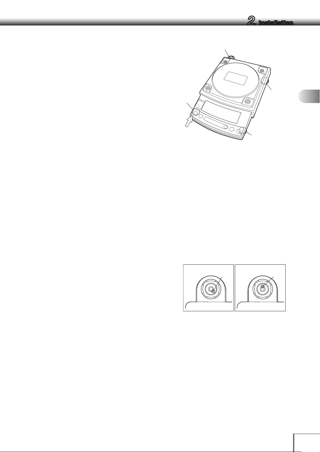
4 This balance has three level screws (adjustable
Level indicator
g
Lef
①
②
eB
feet) at the right front, left front and right rear
corners.
Turning a level screw clock-wise stretches the leg
to raise the balance body there. Turning
anticlockwise withdraws the leg and lowers the
balance body.
The level indicator locates at left rear. The bubble
of it is off center when the balance is not placed
level.
(1) At first, adjust only with the two front
screws. Then, turn the right rear level screw
anticlockwise to withdraw its leg
①
completely.
③
Level
screw
t front
2. Installation
1
Level
83[
J
screw
(At the shortest
point when startin
adjustment)
2
3
③
Level screw
4
[Large pan model]
5
While adjusting level screws and observing the
bubble, gently press the left front corner of the
balance ② so that both front level screw feet ③
are touching the table surface.
(2) Bubble moves to the highest position.
Therefore, adjust level screws ③ so that the
balance main body is lowered in the direction
of the bubble.
Case 1: Right front of the balance is too high.
Turn right front level screw anticlockwise so that the bubble moves
towards center.
Case 2: Front of the balance is too low. Turn
both front level screws clockwise so
that the bubble moves towards center.
(3) When the bubble has come to the center of the
red circle, turn the right rear level screw
clockwise until its foot softly touches the table
surface. Verify the balance sits stable with four
feet.
Case 1 Case 2
Bubbl
6
7
8
9
ubble
10
11
12
13
14
11
Page 26
2. Installation
Cu
Positioners
Large pan
Positioners
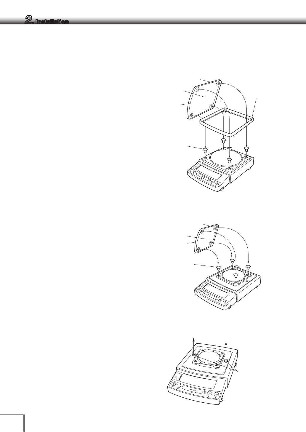
5 Install the pan. With small pan model with
minimum display of 0.001g, the standard
windbreak is also installed here.
a. Large pan model
(1) Insert the four pan supporter caps into the
holes in the top of the balance.
(2) Next, align the large pan windbreak with
the frame and set in place
(3) Lastly, set the pan so that the positioners
on the back of the pan precisely align with
the pan supporter caps as shown in the
figure.
Pan
rved
front
Pan supporter
caps
windbreak
(0.01 g
models only)
83[
b. Small pan model
(minimum display 0.01g ∙ No
windbreak)
Insert the four pan supporter caps into the holes
in the top of the balance. Place the pan gently on
pan supporter caps. Positioners of the pan must
fit pan supporter.
The rubber caps on top of the main body may be
replaced with the stainless screws so that it will be
more secure when exposed to organic solvent.
b. Small pan model
(minimum display 0.001g, windbreak
standard)
(1) Pull out the two rubber caps from the
main body top.
Pan
Curved
front
supporter
caps
Pan
83[
12
83[
Rubber caps
Page 27
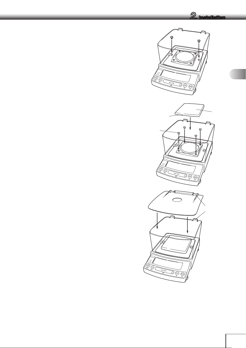
(2) Fit windbreak main on top of the balance main
body, and fasten it with two fixing knobs. In
cases where there is any risk of organic
solvents coming into contact with the main
body, use the included stainless steel screws
to fasten the windbreak instead of the fixing
knobs.
(3) Insert the four pan supporter caps into the
holes in the top of the balance. Place the pan
on them. Positioners on the pan must fit pan
supporter caps.
Pan
supporter
caps
UP0000x
3
Curved
front
2. Installation
Pan
1
2
3
4
5
6
(4) Place windbreak lid on top of windbreak main
fitting the hinge parts.
83[
7
8
9
Hinge parts
10
11
83[
12
13
14
13
Page 28
2. Installation
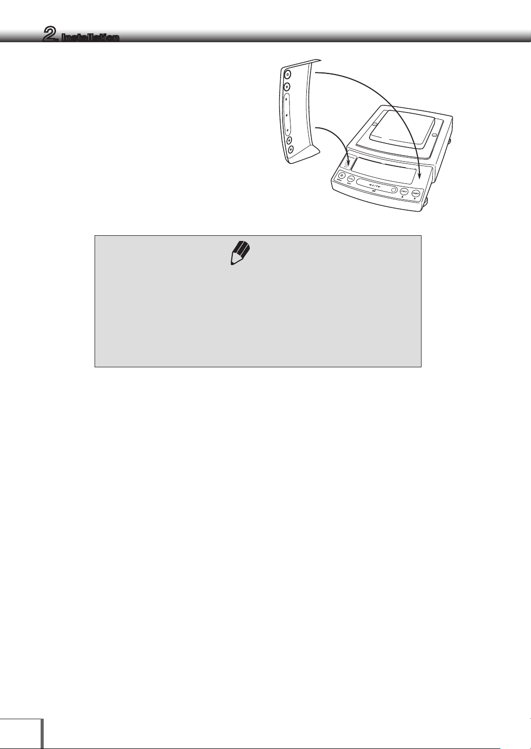
6 If you use in-use protective cover, peel off the
paper to expose the adhesive on it, then fit it on
the display and key part. Press the adhesive
parts gently.
Using a verified balance as a legal measuring instrument in using
region:
Legal regulations require a verified balance be sealed. This control seal is a
self-destructive adhesive label. This seal is irreparably damaged invalidating
the verification, if you attempt to remove it. The balance must then be reverified before it is used for legal measurements.
Note
UP0000x
3
14
Page 29
2.4 Turning on the Power
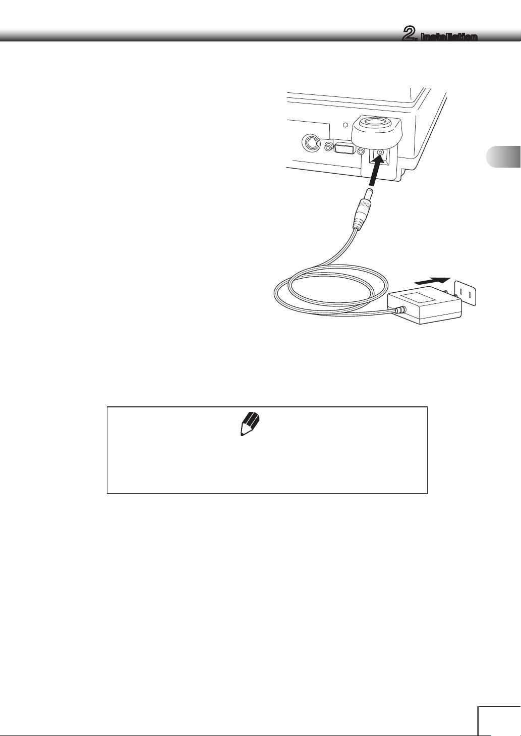
1 Insert the AC adapter plug into the DC IN
connector on the back of the balance.
2 Insert the AC adapter into the power source.
The balance self-check is activated and the
following messages are displayed in the order
indicated.
First, the software version number is displayed.
(Balance self-check display)
[5.00:00]→[CHE 5]→[CHE 4]→
[CHE 3]
→[CHE 2]→[CHE 1]→[CHE 0]→ prompting all
the symbols and segments →[oFF]
* e.g. of the versio n number
([CHE 5] and [CHE 4] are not displayed for the
UPY Series)
2. Installation
1
2
3
4
5
6
3 Press [POWER] key.
All the symbols and segments prompt and then
the display changes to indicate the gram-display.
The backlight is illuminated.
If display all mode (→14.4) is selected, the balance will stop in the display all
state.
Press the [O/T] key afterwards to switch to g display.
Note
* The actual AC adapter shape may be different.
7
8
9
10
11
12
13
14
15
Page 30
2. Installation
2.5 Span Calibration
Note
Using a verified balance as a legal measuring instrument in using region:
Span calibration must be performed once the balance is installed and before
using the balance as a legal measuring instrument in using region. Span
calibration must be performed with the internal calibration weight to
maintain the verification valid. The balance must be connected to power and
warmed up for at least 2 hours prior to span calibration and use as a legal
measuring instrument.
It is necessary to calibrate the balance after it is moved.
Verify that the balance is stable before performing the span calibration. To achieve a very stable state,
ensure that the balance has been turned on with the gram-display for at least one hour, that the
temperature is constant, that there are no breezes or vibrations and that the balance is in an area isolated
from the normal traffic flow.
When carrying out span calibration, it is necessary to make sure the balance
is as stable as possible. In order to ensure this stability, turn the power to the
g display for at least 1 hour and allow the temperature of the balance to
stabilize after installation, before carrying out calibration.
UPX Series
[Span Calibration Using the Builtin Weight]
1 Verify that the balance is in gram-display and
that the pan is empty.
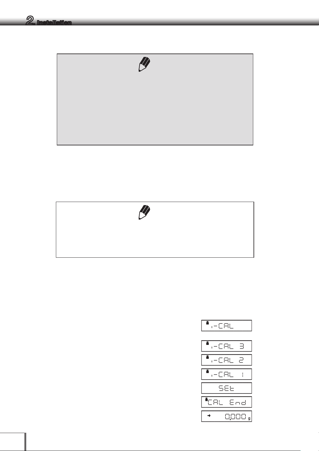
2 Press the [CAL] key once. “i-CAL” is displayed.
3 Press the [O/T] key.
After [i-CAL3] ~ [i-CAL 1] , [SEt] , [CAL End]are
displayed indicating the completion of span
calibration, the gram-display will appear.
Note
This is the standard calibration type. Refer to " 7 for Calibration".
16
Page 31

UPY Series
[Span Calibration Using External Weights]
2. Installation
Not applicable to a verified balance as a legal measuring instrument in using
region.
1 Verify that the balance is in gram-display and
unload the sample from the pan.
2 Press the [CAL] key once. “E-CAL” is displayed.
3 Press the [O/T] key.
The value of the correct calibration weight to be
loaded is displayed and blinks.
Change the weight value to be used
Press the [CAL] key to change the weight value.
Adjust the value using the [UNIT] key and [PRINT]
key then press the [O/T] key. This will set the
modified weight value. Press the [POWER] key to
interrupt modification.
Refer to 5.4 for numerical value input methods.
The range of weights that can be used for
sensitivity calibration is designated separately for
each model. Refer to "External weight calibration
ranges" in "A1. Specifications".
Note that attempting to input a value outside of
the range will cause an error.
4 Load the indicated calibration weight and press
the [O/T] key.
Note
(Example)
UP0000x
3
1
2
3
4
5
6
7
8
9
10
11
12
13
14
17
Page 32

2. Installation
5 When the zero display blinks, unload the weight
from the pan and press the [O/T] key.
[SEt], [CAL End] is displayed briefly to indicate
completion of span calibration. Then the gramdisplay will return.
Span calibration should be performed again : when the location of the
balance is changed, when the room temperature changes considerably,
periodically, according to the quality control plan of the user.
Note
18
Page 33

UP0000x
3
UP0000x
3
3. Basic Operation The bala nce can be used co rrectly acc ording to the co ntent of Chapte rs 1 to 4
3.1 Weighing
1 If a weighing vessel (tare) is used, place it on the
pan and wait for the stability mark to prompt.
1
2
2 Once the display stabilizes, press the [O/T] key.
This will zero the display.
The stability symbol will display to indicate
stability.
3 Place the object to be weighed on the pan.
4 Read the displayed value after the stability mark
is displayed.
Using a verified balance as a legal measuring instrument in using
region:
Indicates that the balance is set exactly to “Zero” with the zero-setting
function (+/-0.20e: e = verification scale interval).
Note
3
4
5
6
7
UP0000x
3
8
9
10
11
12
13
14
19
Page 34

3. Basic Operation
Using a verified balance as a legal measuring instrument in using
region:
The balance must be used within the temperature range indicated on the
verification label.
When PSC (refer to 7. 3. 2), fully-automatic span calibration, is not activated,
operator must carry out span calibration with the built-in weight (refer to 2.5)
upon blinking of the Weight Symbol.
Error Displays During Weighing
Display
[oL] will be displayed if the weighing capacity or measurement ranges are
exceeded.
[-oL] will be displayed when the load on the balance is too light because the pan is
misaligned or due to other causes.
Note
3.2 Changing the Unit Display
Every time the [UNIT] key is pressed, the unit display changes sequentially among those set-up. Gram, %,
and PCS have been set-up before delivery.
Notes
• Before a unit can be displayed it must be registered in "9. Unit Display
Set-up".
• Unplugging then re-plugging in the AC adapter will automatically switch to
g units (registration is saved).
20
Page 35

4. Menu Item Selection (Rea d Chapters 4 to 12 bef ore usi ng the balanc e)
4.1 What is the Menu?
The UP Series is equipped with a number of useful functions. Menus are provided to allow customers to
efficiently select the functions suited to their usage purposes and configure optimal settings. Configuration
of these settings is referred to as "menu settings". Familiarize yourself with the menu setting procedures to
utilize the UP Series functions. Prepare a menu map when configuring menu settings.
1
2
4.2 Menu Map
In the UP Series, menus are broadly categorized into 7 groups, and these can then be divided into further
subgroups where necessary. A menu map is a diagram which illustrates the tree structure of these menus
in an easy to understand manner. It is useful for allowing quick access to the menu items you wish to use.
Menu maps are provided on the operation explanation sheet and in A2.
3
4
5
6
7
8
9
10
11
12
13
14
21
Page 36
4. Menu Item Selection
4.3 Menu Item Selection Procedure
Refer to Menu Maps (explanatory operation sheet and A2. at the end of this document).
UP Series menus are composed of 4 menu levels. Press the [CAL] key three times during mass display to
open the menu. Key operations during menu usage are as shown below.
Key Short press
[POWER] Return to previous (1 step higher) menu level. Return to mass display
[CAL] Move to next menu item. No operation
[O/T ] Confirm menu or move to next menu level. No operation
[UNIT]
[PRINT]
Increases the blinking (selected) digit by +1 when
setting numerical values.
Changes the blinking (selected) digit when setting
numerical values.
Press and Hold for
About 3 Seconds
No operation
No operation
Movement
direction on
menu map
←
↓
→
This instruction manual identifies each menu item by a
Detection Band ” of “8. Environment” are 27 through 33. In the menu map you can see it would be
entered in the order "Menu group 3 (E blinking)" → "Stable detection width".
Example: Select “Stability Detection Band” “4 counts”. The menu item number is 29 on the Menu Map.
The procedures are as follows.
(Menu level 1)
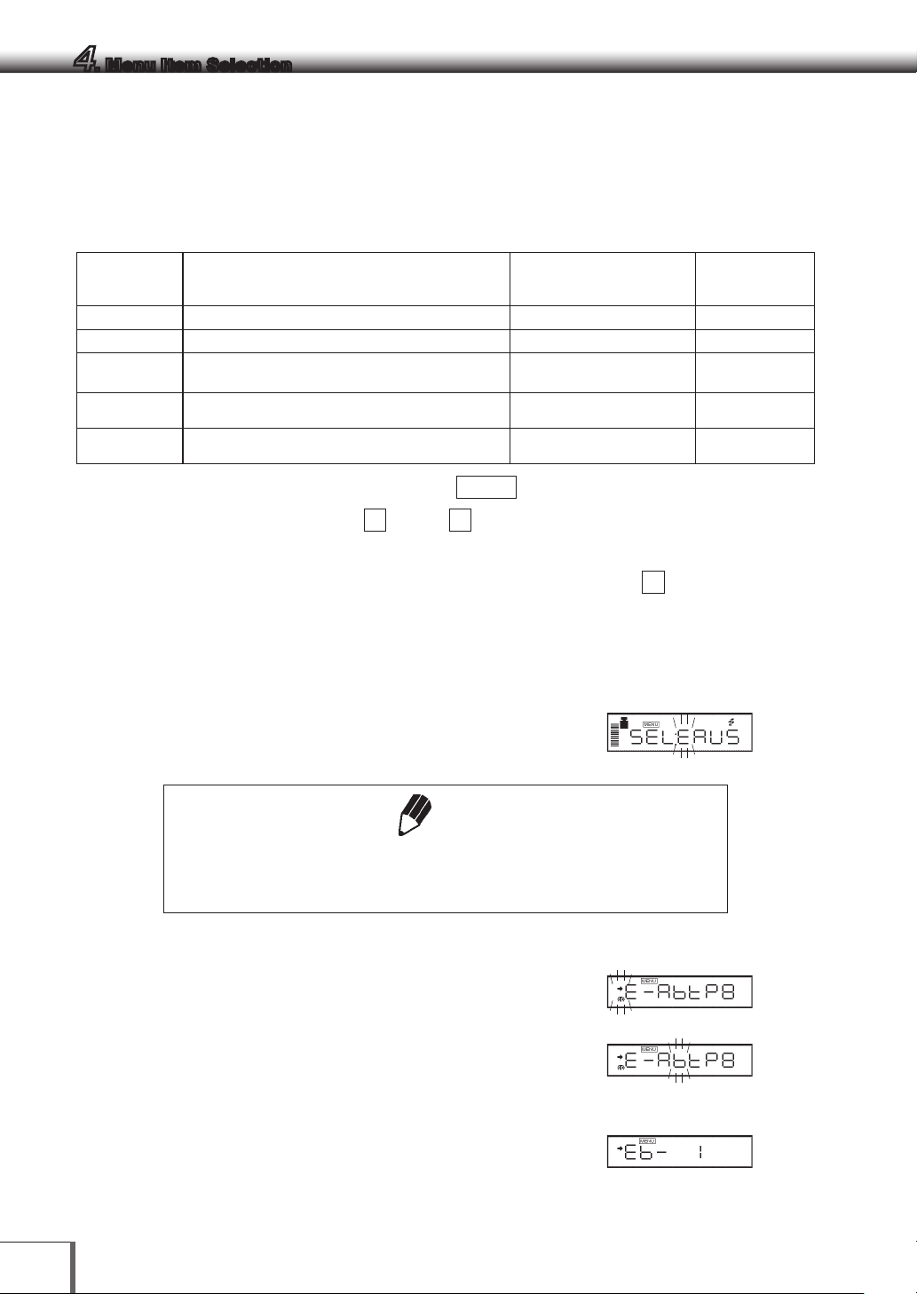
1 Press the [CAL] key repeatedly from the gram
display until “SEL:EAUS” and some symbols are
displayed and “E” blinks.
number
. For example, the menu items of “Stability
Note
Different operations are carried in some cases when using units other than g.
Set the display to g then press the [CAL] key.
2 Press the [O/T] key to select this item.
The [→] in [→E-AbtP8] will blink.
3 Press the [CAL] key 2 times to display the next
item.
The [b] in [→E-AbtP8] will blink.
4 Press the [O/T] key to select this item.
The display will show [Eb-1]. If [Eb-1] is selected
the stability symbol will be displayed.
22
Page 37

5 Press the [CAL] key 2 times to display the next
71
24356
item.
The display will show [Eb-4].
4. Menu Item Selection
Important Note on Menu Item Selection
Even the desired menu item is reached and displayed, it is not yet set unless Stability mark ( ) is
prompted with it. Do not fail to press [O/T] key to put Stability mark before returning to the mass
display.
6 Press the [O/T] key to select this item.
“SEt” is displayed and the stability mark now
appears.
7 Return to the desired menu by pressing the
[POWER] key.
If pressed and held, it returns to the gramdisplay.
Other menu items can also continue to be
selected.
Menu level 1 menu groups
Menu Group
1
2
3
4
5
6
7
Symbol that blinks at
beginning of menu
Symbol
Graphic display Analog display, checkweighing, and target weighing
E (Environment) Installation environment and taring
A (Application) Application measurements and automatic output
U (Unit) Unit conversion and specific gravity measurement
S (System) Clock set-up and calibration record
Symbol
Calibration
Communication with computer and external devices.
Menu Items Included
1
2
3
4
5
6
7
8
9
10
11
12
+,
*2
/2
13
14
23
Page 38

4. Menu Item Selection
Exiting from menu settings
Press and hold the [POWER] key for approximately three seconds during menu settings to return to mass
display.
24
Page 39

4. Menu Item Selection
4.4 Setting Numeric Values
In the UP Series, various settings such as external sensitivity calibration weight value input, checkweighing
for setting threshold values, and medium density during specific gravity measurement, are input as numerical
values in some cases. (see 8.2, 8.3, 11.1, 11. 5 , 11.7 for detail of each item.)
In a menu used to set numeric values, [MENU] and [ ] are both prompted and the digit to be input blinks.
Press the [PRINT] key to move the blinking digit one place to the right.
1
2
Press the [UNIT] key to increase the value of the blinking digit by one.
Press the [O/T] key to store the displayed value in the balance memory.
…“SEt” is displayed when the value has been successfully saved.
…“Err” is displayed when the balance failed to save the value.
Press the [POWER] key to stop numeric entry. “Abort” is displayed briefly and the
display returns to the menu, one level up.
Notes
When setting decimal points (solid specific gravity measurement, liquid
specific gravity measurement, user unit multiplier settings)
1. Press the [PRINT] key repeatedly until the last digit is blinking.
The ▼ symbol or current decimal point will blink, and decimal point
position setting mode will start.
2. Press the [UNIT] key.
The selected decimal point position will move to the right (equivalent to a
value of × 10), so continue pressing until the desired position is blinking.
3. Press the [O/T] key to set the decimal point position. “SEt” is displayed
briefly to indicate that the setting is completed.
Use the optional AKB-301 Application Keyboard to easily set numerical values and decimals.
…
3
4
5
6
7
8
9
10
11
12
13
14
25
Page 40

4. Menu Item Selection
4.5 Related Useful Functions
4. 5.1
This function is convenient when an application requires frequent changes to a specific menu item.
During mass display or menu selection, press and hold the [CAL] key for approximately three seconds.
The last menu item that was changed or set is displayed.
4.5.2
If you are unsure of the configured settings when using the menu, reset the menu. This will restore the
menu to the default settings. Default settings are indicated on the menu map with a # symbol.
Note that PSC will be on (menu
Select menu 72 to reset the menu. Use the following procedures.
Last Menu Recall
Returning to the Default Settings (menu reset)
5
) after a menu reset.
1 In the gram-display, press the [CAL] key
repeatedly until the “S” of “SEL:EAUS” blinks.
2 Press the [O/T] key. [S-dtSCr] =The Menu Group
6 is selected.
3 Press the [CAL] key until the [r] in [S-dtSCr,] is
blinking.
4 Press the [O/T] key to display “rESEt?”
5 Press the [O/T] key again. “rESEt” is displayed to
indicate menu reset completion.
6 Press the [POWER] key several times (or hold it
for approximately 3 seconds) to return to the
gram-display.
• The settings made in “12.6 Decimal Point Symbol in Output Data” and “5.2
Date Output Style” are not be cleared with Menu reset.
• Environmental setting of Pouring mode (8.2) is not cleared with Menu reset.
• Operational condition setting of Animal Weighing mode (11.6) returns to the
default (Cond 1).
26
Notes
Page 41

4. Menu Item Selection
4.5.3
In the UP Series, menu settings can be locked to prevent any accident or erroneous menu changes. This
feature is called "Menu lock".
Menu Lock can be activated or released only at the “oFF” display immediately after the balance is
connected to the power.
(How to lock the menu)
Menu Lock
1 Disconnect power from the balance once. Then,
reconnect power to the balance.
2 Press and hold down the [CAL] key for about
three seconds during “oFF” display.
“LoCKEd” is briefly displayed to indicate that the
menu is locked.
Notes
• is illuminated during “oFF” display or STAND-BY while Menu Lock
is activated.
• “LoCKEd” is displayed upon an attempt of access to the menu including
releasing the currently set function, while Menu Lock is activated.
• The operational condition setting for Animal Weighing (11. 6) and the
environmental setting for Pouring mode (8.2) are also locked under Menu
Lock.
• Change of minimum display (See 6.2, 11.1, 11.2) is not locked by Menu
Lock, also change of unit display (See 3.2) is not locked by Menu Lock.
• If the menu lock is enabled, the date and time printing when pressing and
holding the [PRINT] key for 3 seconds, and the PRINT +, DATE=, TIME=,
and TIME command operations will also be locked.
1
2
3
4
5
6
7
8
9
10
(How to remove Menu Lock)
1 Disconnect power from the balance once. Then,
reconnect power to the balance.
2 When “oFF” is displayed, press and hold down
the [CAL] key for about three seconds.
3 “rELEASE” is briefly displayed to indicate that the
menu lock has been turned off.
11
12
13
14
27
Page 42
5. Built-in Clock Set-up
The built-in clock has to be set up in advance if a calibration record is to be produced or Clock-CAL
function is to be used.
5.1 Date
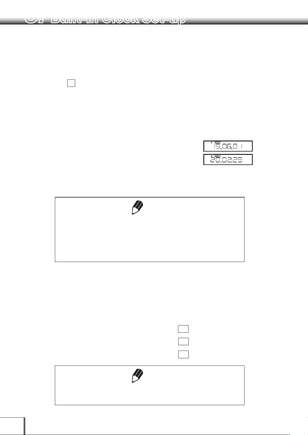
1 Select menu
the year, the month, and the day, in that order.
Press the [UNIT] key to increase the blinking
(selected) digit by 1.
Press the [PRINT] key to move the selection to
the next digit to the right.
Example: June 1st, 2019, set as "19.06.01"
Example: February 29th, 2020, set as “20.02.29”
63
, and set the last two digits of
2 Press the [O/T] key once the date is set. This will
record the set date.
Notes
The built-in clock will automatically compensate for leap years, however no
checks will occur when configuring settings.
When the [O/T] key is pressed in step 2, the seconds will be set to 0, so if the
date is set after the time is set, the seconds setting will be incorrect. Set the
time after setting the date.
(Example)
5.2 Date Output Style
When outputting the date from the balance built-in clock to an external device, the date to be output can
be selected from three different styles of day, month, and year order. The order will not change when
displaying the date on the balance.
To output in the YYYY-MM-DD order, select menu item
To output in the DD-MM-YYYY order, select menu item
To output in the MM-DD-YYYY order, select menu item
Notes
The setting made here on “Date Output Style” will not be cleared with Menu
reset (See 4.5.2).
28
63a
63b
63c
. [ y.m.d]
. [d.m.y]
. [m.d.y]
Page 43

5.3 Time
Select menu item 64 and set the time in the
24 hour system using the [UNIT] and [PRINT] keys,
then press the [O/T] key.
5. Built-in Clock Set-up
1
Example: 1:23 in the afternoon, is set as “13:23”.
Note
The moment the [O/T] key is pressed seconds are set to 00.
(Example)
5.4 Setting Display During Stand-by
Determine what is to be displayed during stand-by.
To display the time during stand-by, select menu item 65 [SS-t]
To display the date during stand-by, select menu item 66 [SS-d]
To display neither during stand-by, select menu item 67 [SS-no]
When displaying the time during power supply standby, press the [UNIT] key to display or hide the
seconds.
2
3
4
5
6
7
8
9
10
11
12
13
14
29
Page 44
6. Display Selection
6.1 Bar graph display
The relative amount of the load on the pan is displayed in the bar graph. This feature helps to prevent
errors due to OL (overload) status. This display can not be used with the Check weighing or Target mode.
A bar displayed in the lower areas of the scale
indicates that the load on the pan is small. (1)
A bar displayed up to the upper areas of the scale
indicates that the load on the pan is close to the
weighing capacity. (2)
Select the menu item 11 to set up Full Scale mode.
Not to display bar graph, select menu item 21
(Examples) (1) (2)
6.2 Changing the Minimum Display Digit
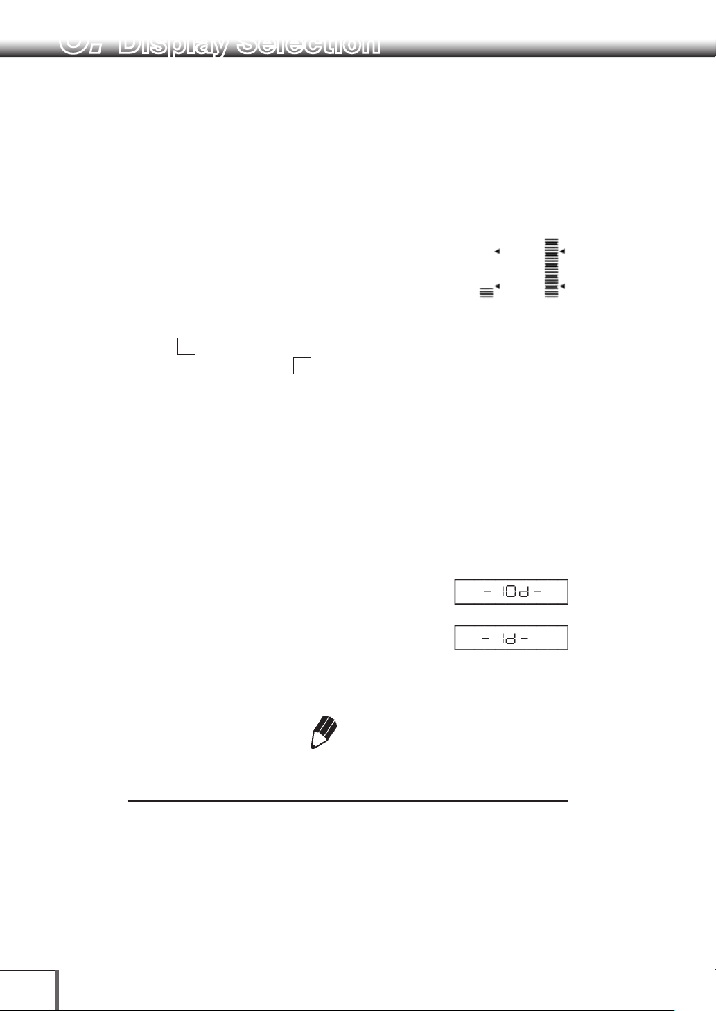
It is possible to decrease the minimum balance
display by one decimal place if necessary.
1 Press and hold the [UNIT] key for approximately
three seconds. “- 10d -” is displayed and the
display is decreased by one decimal place.
2 Press and hold the [UNIT] key for approximately
three seconds. “- 1d -” is displayed and the
display returns to the original number of decimal
places.
The location of the decimal point in the display does not shift. In the “10d”
display, the last digit is empty.
30
Note
Page 45

7. Calibration
7.1 What is calibration?
Calibration is required to accurately weigh items with an electronic balance accurately. Calibration should
be performed:
• When the location of the balance is changed, even within the same room.
• When the room temperature changes considerably.
It is recommended that calibration be carried out every day before use.
1
2
In this instruction manual, the terms span calibration, calibration check, and calibration are used as
follows.
Span Calibration: … Use of a reference mass (calibration weight, etc.) to calibrate the
sensitivity of the balance correctly.
Calibration Check: … Use of a reference mass (calibration weight, etc.) to determine the
amount of drift of the balance sensitivity.
Calibration: … Pertains to both span calibration and calibration check.
Caution
!
Never plug off the balance when the following messages are displayed.
[i-CAL x] [i-tESt x] [wAit] [Abort] [CAL E x] (x represents a number)
In the UPX Series, the built-in weight is not locked in this state, so if the balance
is picked up or moved in this state, it could cause damage to internal
mechanisms. In the event the power supply is disconnected while this
indication is displayed, wait for approximately 10 seconds, then reconnect the
power supply. The [CHE 4] indication time may be slightly longer than normal
in these circumstances.
3
4
5
6
7
8
9
10
Notes
If the following indications are displayed, the balance has not undergone
proper span calibration.
[CAL E1] When the balance will not stabilize
[CAL E2] When there is serious balance zero point drift
[CAL E4] When there is serious balance sensitivity drift
[CAL E5] When the incorrect weight is placed on the balance
11
12
13
14
31
Page 46
7. Calibration
7. 2 Calibration Execution
Notes
• Setting before shipment is as the following:
UPX Series: Span calibration using the built-in weight ([i-CAL])
UPY Series: Span calibration using external weights ([E-CAL])
The type of calibration can be changed (See 7.3).
• Calibration will not be performed when the weight on the pan is not near
zero, or the balance is not stable.
7. 2 .1
The balance is adjusted using the built-in calibration weight.
Span Calibration Using the Built-in Weight (UPX Series Only)
1 Verify that the balance is in mass display and that
the pan is empty.
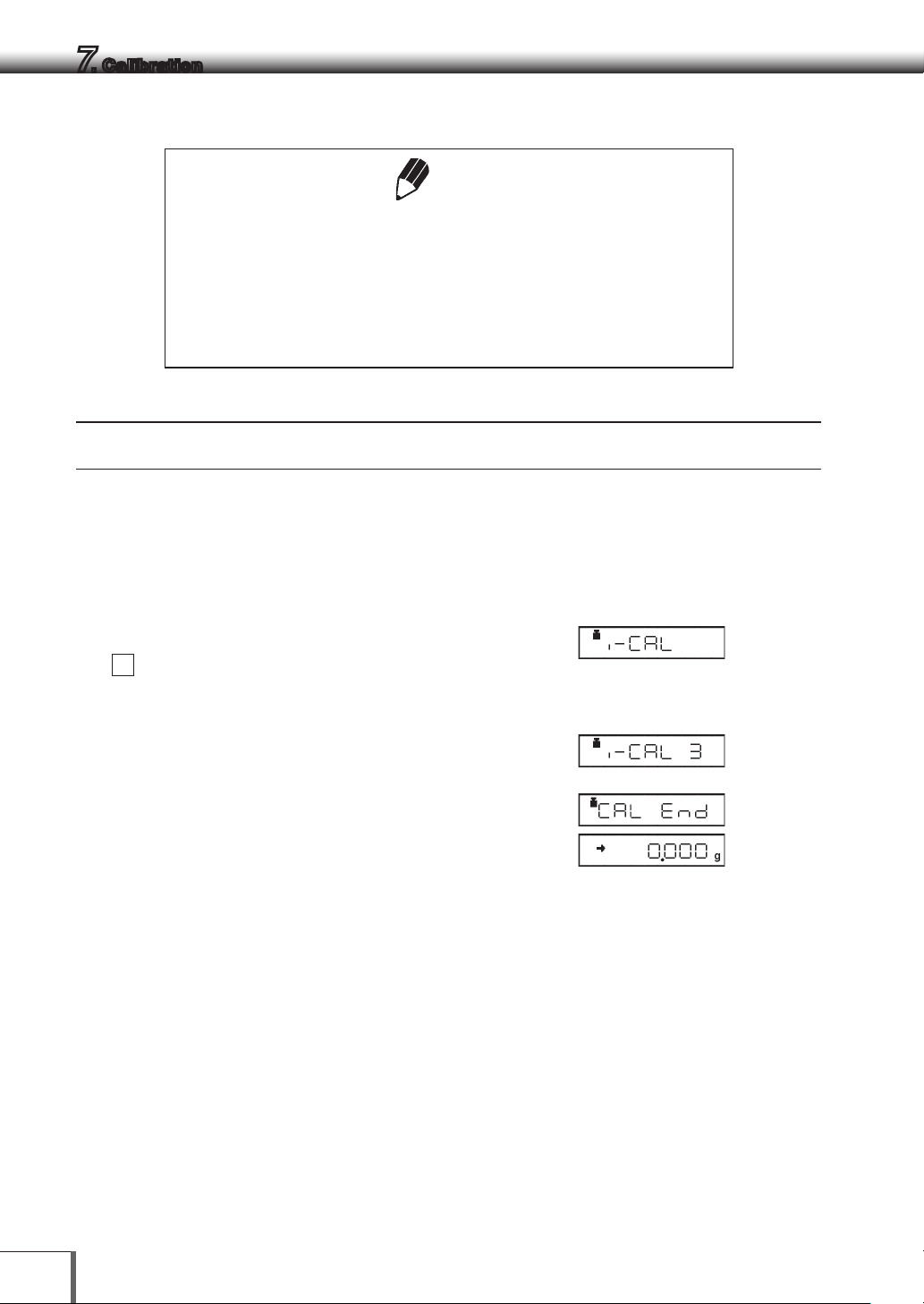
2 Press the [CAL] key once. “i-CAL” is displayed.
If this indication is not displayed, select menu
1
.
Press and hold the [POWER] key for three
seconds after selecting to return to the g display.
3 Press the [O/T] key
[ i-CAL3 ] ~ [ i-CAL 1], [ SEt ], [ CAL End] will be
displayed in that order. Then the mass display
will appear indicating the completion of span
calibration.
…
32
Page 47

7. Calibration
7.2.2
Use of the built-in weight to check and display the degree of balance sensitivity drift.
Calibration Check Using the Built-in Weight (UPX Series Only)
1 Verify that the balance is in mass display and that
the pan is empty.
2 Press the [CAL] key once to display “i-tESt”.
If “i-tESt” is not displayed, return to mass display
and select menu item 2.
Press and hold the [POWER] key for three
seconds after selecting to return to the g display.
3 Press the [O/T] key.
The display changes sequentially from “i-tESt 2”
to the “d xxx” display. (xxx indicates a numeric
value)
This “d” value indicates the difference between
the current calibration weight reading and the
calibration weight reading at the last span
calibration.
1
2
3
4
5
6
7
4 To perform span calibration, change the “d”
value to zero, by pressing the [CAL] key.
“CALEnd” is displayed, indicating the completion
of the calibration check.
Press the [O/T] key to avoid changing the “d” value to
zero. (Pressing the [POWER] key interrupts calibration
and does not change this value to zero.)
Changing the “d” value to zero is equivalent to performing span calibration.
8
9
10
11
Note
12
13
14
33
Page 48

7. Calibration
• The [xxx] numbers displayed in the [d xxx] are the estimated value of the
• Error codes that may be displayed:
Note
drift of the balance display when a weight close to the weighing capacity
is placed on the balance. For example, if [d - 0.3 g] is displayed for the
UP4201X (weighing capacity 4,200 g, minimum display 0.1 g), this
indicates that 3,999.7 g would be displayed if a 4 kg calibration weight
was placed on the balance.
[d ouEr ] (d OVER) indicates that the “d” value is 1000 counts or more.
[d UndEr ] (d UNDER) indicates that the “d” value is -1000 counts or less.
34
Page 49

7. Calibration
7. 2 . 3
Not applicable to a verified balance as a legal measuring instrument in using region
The balance is adjusted using your external standard calibration weight(s).
Span Calibration Using External Weights
1 Verify that the balance is in mass display and that
the pan is empty.
2 Press the [CAL] key once. “E-CAL” is displayed.
If “E-CAL” is not displayed, return to mass display
and select menu item 3.
3 Press the [O/T] key.
The value of the correct calibration weight to be
loaded is displayed and blinks.
Changing the Calibration Weight to be Used
Pressing the [CAL] key allows changes to the weight
value. Modify the value using the [UNIT] key and
[PRINT] key, then press the [O/T] key. Refer to 4.4 for
how to make numerical input. To interrupt
modification, press the [POWER] key.
Calibration range with external weights is designated
to each model. Refer to “1. Specifications” for
calibration range. Attempt of inputting an invalid
calibration weight value causes an error message.
(Example)
1
2
3
4
5
6
7
8
9
4 Load the indicated calibration weight and press
the [O/T] key.
5 Shortly, zero display blinks. Unload the weight
from the pan and press the [O/T] key.
“SEt” is displayed briefly to indicate completion
of span calibration.
OIML Class E2 or F1 calibration weight is recommended for calibration,
depending on your accuracy demand.
Note
10
11
12
13
14
35
Page 50

7. Calibration
7. 2 . 4
Not applicable to a verified balance as a legal measuring instrument in using region
Use of a standard calibration weight to check and display the degree of balance sensitivity drift.
Calibration Check Using External Weights
1 Verify that the balance is in mass display and that
the pan is empty.
2 Press the [CAL] key once to display “E-tESt”.
If “E-tESt” is not displayed, select menu item 4.
3 Press the [O/T] key.
The value of the correct calibration weight to be
loaded is displayed and blinks.
Changing the Calibration Weight to be Used
Pressing the [CAL] key allows changes to the weight
value. Modify the value using the [UNIT] key and
[PRINT] key, then press the [O/T] key. Refer to 4.4 for
how to make numerical input.
To interrupt modification, press the [POWER] key.
Calibration range with external weights is designated
to each model. Refer to “1. Specifications” for
calibration range. Attempt of inputting an invalid
calibration weight value causes an error message.
(Example)
4 Load the indicated calibration weight and press
the [O/T] key. The zero display blinks.
5 Unload the weight from the pan and press the
[O/T ] key.
The display changes to the “d xxx” display.
6 Hereafter the procedure is the same as item 4 in
7.2.2. Calibration Check Using the Built-in
Weight.
36
Page 51

7.3 Calibration Setting
7. Calibration
7. 3 .1
Set the calibration type that will be used in Calibration Execution.
Not applicable to a verified balance as a legal measuring instrument in using region
7. 3 . 2
The UPX Series is equipped with a function (PSC Function) which automatically carries out span
calibration when the ambient temperature changes so that such changes do not impact measurement.
This function can be turned ON and OFF using the following procedure.
Selecting the Calibration Type
To set up “Span calibration using the built-in weight”, (UPX Series only) Select menu item 1.
To set up “Calibration check using the built-in weight”, (UPX Series only) Select menu item 2.
To set up “Span calibration using external weights”, Select menu item 3.
To set up “Calibration check using external weights”, Select menu item 4.
PSC Fully-automatic Calibration (UPX Series only)
1 To turn ON the PSC function, Select menu item
5
2 To turn OFF the PSC function, Select menu item
6
1
2
3
4
5
6
7
8
9
10
11
12
13
14
37
Page 52

7. Calibration
• The weight symbol will blink for approximately two minutes before the
• The following conditions must all be satisfied for the set time in order for the
Notes
automatic span calibration occurs when a temperature change is detected.
If PSC starts while the balance is in use, press the [POWER] key to abort
that cycle.
PSC function to be executed. If these conditions are not satisfied within 1
minute of the specified time, automatic span calibration will not be executed
and that cycle will be skipped.
· The balance must be in mass display mode
· If in mass display mode, the display must be within a 30 count
· The balance must be in a stable state (the stability symbol must be
displayed if in the mass display mode)
· The load on the pan must be near zero
· No other automatic span calibration (PSC or timer CAL) must have
occurred during the same time
Note
Using a verified balance as a legal measuring instrument in using region:
When PSC, fully-automatic span calibration, is not activated, operator must
carry out span calibration with the built-in weight (refer to 7.2 .1) upon blinking
of the Weight Symbol.
If PSC starts while the balance is in use, press the [POWER] key to abort that cycle.
38
Page 53

7. Calibration
7.3.3
In the UPX Series, automatic span calibration of the balance can be carried out at a set time.
It is possible to set up to three specific times for Clock-CAL (“tCALt1”, “tCALt2”, and “tCALt3”). Use the 24
hour system to set menu items 7, 8 and
• Setting to “00:00” releases the function.
Clock-CAL Fully-automatic Calibration (UPX Series only)
9
.
Notes
To execute Clock-CAL, all of the following conditions must be satisfied at the set
time. If these conditions are not satisfied within one minute, the automatic span
calibration is not executed and that cycle is skipped.
• There must be nothing on the pan.
• The balance must be in mass display or the standby mode.
• If in mass display mode, the display must be within a 30 count
• The balance must be stable. (The stability symbol must be illuminated
during mass display.)
• Load on the pan should be near zero.
• No other automatic span calibration (PSC or timer CAL) must have
occurred during the same time
1
2
3
4
5
6
7
Example: Setting “tCAL t1” to twelve noon.
1 Select menu item
7
2 Set the desired time.(Refer to 4.4 for numerical
input.)
(Example)
3 Press the [O/T] key. The set time will be stored.
4 Proceed to next time setting by the [MENU] key,
or return by the [POWER] key.
Skipping Clock-CAL
If Clock-CAL starts while the balance is in use, press the [POWER] key to abort that cycle.
8
9
10
11
12
13
14
39
Page 54

7. Calibration
7. 3 . 4
Not applicable to a verified balance as a legal measuring instrument in using region
PCAL is used to calibrate the built-in weight to a standard calibration weight that is correctly calibrated,
traceable and/or certified. The administrator should set this password (refer to 7. 3 . 5 ).
PCAL: Calibration of the Built-in Weight (UPX Series only)
Notes
If this built-in weight calibration is executed when no accurate standard
weight is available, span calibration and calibration checks using the built-in
weight will not be able to be carried out accurately. Always use a correctly
calibrated, accurate standard weight to carry out built-in weight calibration.
1 Unload the sample from the pan and verify a zero mass display.
2 Select the menu item
10
[PAS:0000 ] is displayed.
3 Enter the PCAL password using the [UNIT] and
[PRINT] keys, then press the [O/T] key.
After “PCAL 3” is displayed, the value of the
standard weight to be loaded blinks.
(Example)
Changing the Calibration Weight to be Used
Pressing the [CAL] key allows changes to the weight
value. Modify the value using the [UNIT] key and [PRINT]
key, then press the [O/T] key. Refer to 4.4 for how to
make numerical input. To interrupt modification, press
the [POWER] key. Calibration range with external weights
is designated to each model. Refer to “1. Specifications”
for calibration range. Attempt of inputting an invalid
calibration weight value causes an error message.
4 Load the standard weight displayed, and press the
[O/T ] key.
Soon, zero is displayed and blinks.
5 Unload the weight and press the [O/T] key.
The display proceeds to “PCAL 0”. When the mass
display appears, calibration is complete.
40
Page 55

Notes
• “SEt” is displayed during the process. Leave the balance in a stable state
until the mass display appears as in step 5.
• In PCAL, the value of the “weight to be loaded” cannot be changed.
• Set the PCAL password using menu item 71 (The default value is 9999.)
7. Calibration
1
2
3
7.3.5
Not applicable to a verified balance as a legal measuring instrument in using region
This password is necessary to access the PCAL function.
It is recommended that the balance administrator set this password to prevent an unauthorized person
from incorrectly calibrating the built-in calibration weight.
Select menu item 71 .
The numerical setting display appears. Enter a 4-digit number from “0000” to “9999”.
Refer to 4.4 for numerical input.
PCAL Password Setting (UPX Series only)
Note
When the menu is reset, the PCAL password is reset to “9999”.
4
5
6
7
8
9
10
11
12
13
14
41
Page 56

7. Calibration
7.4 Maintaining Calibration Reports… GLP/GMP/ISO
Compliant Measurement Management Systems
These settings should be made by the administrator.
7.4.1
Turns the calibration report function ON/OFF. Use this to generate and output a calibration report as for
GLP, GMP or ISO9000. An electronic printer (optional accessory) is required to print the report.
• Turn the printer, EP-100/-110 date printing, ID printing, etc. off for use.
7.4.2
Individual balances can be identified by the serial number on the main body of the balance. The user can
add a four-digit ID number to the calibration report.
Select menu item 70 . Set a 4-digit number from “0000” to “9999”.
Calibration Report Setting
To create calibration report, select menu item 68 [GLP-on ]
To turn off calibration report function, select menu item 69 [GLP-oFF]
Balance ID Setting
42
Page 57

8. Environment
8.1 Overview
Settings on the balance can be changed to compensate for the installation environment such as the
degree of vibration or air movement or for the purpose of weighing a solid, liquid or powder.
1
8.2 Stability and Response (Averaging)
These settings select the degree of display stability and response.
The UP Series features outstanding stability and response, however in general, stability and response are
contradictory, so if settings are changed to give one or the other priority, it will cause some lose in
performance of the other.
In order to maintain compatibility with the UW/UX Series, the stability and response will be the same as the
UW/UX Series in any mode other than automatic mode.
Automatic mode can be switched between [UP.AUto] UP Series automatic mode, and [PrE.AUto] UW/UX
Series automatic mode.
The current mode is the mode on which the stability symbol is delayed on menus 22 to 26 when the
menu is opened.
Auto mode: Select menu item
The balance automatically performs optimum averaging dynamically while
observing the load data. This is the recommended setting and should be used
unless special circumstances exist.
(To use UW/UX Series automatic mode)
Each time the circle (right side) on the [O/T] key is pressed and held during
automatic mode, the balance will switch between UP Series automatic mode
and UW/UX Series automatic mode. In addition, when the settings are changed
a verification of the new settings will be temporarily displayed in the [ ].
UP Series automatic mode [UP.AUto] →UW/UX Series automatic mode [PrE.
AUto] →UP Series automatic mode [UP.AUto]
During measurement in the UP Series automatic mode the ▶ symbol will be
displayed on the right side of the display.
22
[EA-AUto] (Environment/Averaging-AUTOmatic)
2
3
4
5
6
7
8
9
10
11
12
Pouring mode: Select menu item 23 [EA-PoUr] (Environment/Averaging-POURing)
(Filling, dosing) This mode is particularly suitable for dosing or filling purposes.
Note that this mode is very sensitive to wind and vibration.
(Environmental setting in Pouring mode)
Pouring mode allows further adjustments to the surrounding environmental
conditions. Choose the optimal setting for your installation site observing the
response and stability.
13
14
43
Page 58

8. Environment
(Display)
While “Pouring” is selected as the Stability and Response setting, taring the
container or zeroing the display cannot be made by pressing the rightmost
part of [O/T] key. Press the center or the left part of [O/T] key for taring or
zeroing.
Every time the circle in the right part of the [O/T] key is pressed during weighing in
Pouring mode, the environmental setting will be changed and cycles in the
following order. Upon changing the setting, the new setting is briefly displayed as
sh own in “[]”.
normal environment (“norm E”) → unstable environment, (“UnStb E”) → very
stable environment, (“StAbL E”) → normal environment, (“norm E”).
During use, the current environmental setting of Pouring mode can be confirmed
by observing the position of the symbol in the display.
When [PrE.AUto] is selected
When [UnStb E] is selected
When [norm E] is selected
When [StAbL E] is selected
Note
However, when using animal weighing mode (11.6), the animal weighing mode operation settings and
confirmation display (cond 1 to 3) will take priority.
In addition, this will be used as an indicator to display the status of each mode during animal weighing
mode (11.6), solid specific gravity (11.2), and liquid specific gravity (11.3) weighing, so the environmental
settings for pouring mode will not be displayed.
Standard mode: Select menu item 24 [EA-Stnd] (Environment/Averaging-STaNDard)
This mode is suitable for weighing in a normal environment. Averaging is fixed
and does not change dynamically as in the [EA-AUto] mode.
Anti-vibration mode: Select menu item 25 [EA-v ibr] (Environment/Averaging-VIBRation)
Use this mode when the balance is used in a location where there are large
vibrations and the display fluctuates in the [EA-AUto] mode. Response is
deteriorated at small mass amount changes.
Anti-wind mode: Select menu item 26 [EA-w ind] (Environment/Averaging-WIND)
Use this mode when the balance is used in a location where it is exposed to
airflow that causes the display to fluctuate in the [EA-AUto] mode.
Response deteriorates further than the [EAi-vibr] mode, but weighing is
comparatively stabilized.
Note
44
If weighing cannot be performed efficiently even with the [EA-wind] mode,
change the installation site of the balance or use the optional windbreak
(large).
Page 59

8. Environment
8.3 Stability Detection and Settings
Stability detection is an auxiliary function used for the following purposes.
(1) Stability symbol display: When the weigh is stabilized during measurement, Stability mark is
prompted as an auxiliary indication of measurement stability.
(2) Stability link function operation: Operations such as data output and auto zeroing of the below
listed functions are triggered by stability detection. Some data output functions operated with
communication commands (12.4.3) are also linked to stability detection.
(Functions that employ stability detection)
Auto Print (See 10.3), Auto Zero (See 10.4), Taring/Printing at Stability (See 10.6), Peak Hold (See
11. 3 ), Auto-Memory and Zeroing (See 11. 5 ), Animal Weighing (See 11. 6 ), Formulation Mode (See 11.7).
1
2
3
It is possible to adjust the operation with the following stability detection settings.
It is not usually required to change these settings as they are optimized at default. However, it is allowed to
change according to 8 . 3.1 and 8.3.2 when: wishing to ease the criteria of stability detection under very
unstable environmental or sample conditions, or wishing to accelerate automatic data output when using
a function that employs stability detection.
(a) Stability Detection Band (8 . 3.1)
(b) Timing of Stability Mark Illumination and Automatic Output (8.3.2)
Note
Stability mark is an auxiliary device to inform measurement stability. The
displayed value may change while the stability symbol remains illuminated if
the load is changing slowly, or depending on the stability detection settings.
8.3.1
The default setting is “1 count” and the measurement is regarded to be stable when the display has
remained within one display count for a fixed length of time. If stability detection band is set at “2 counts”,
it will be regarded to be stable when the display has remained within two display counts.
Selecting a larger stability detection band generally eases the criteria and makes stability mark illuminate
more readily. However, it will be more likely for the display to further fluctuate after prompt of stability mark.
Try a larger stability detection band when data outputs triggered by stability detection is slow due to very
unstable environmental and/or sample conditions.
Stability Detection Band
4
5
6
7
8
9
10
11
12
13
Stability detection
band
Menu item number
1 count
(default setting)
27 28 29 30 31
2 counts 4 counts 8 counts
16
counts
32
counts
*
32
64
counts
*
33
*
14
45
Page 60

8. Environment
Only use settings [Eb-16] to [Eb-64] when using auto print, animal weighing
mode, and other functions related to output to accelerate stability symbol
display under strict floor and sample vibration conditions.
Note
8.3.2
The prompt of stability mark and automatic data output of the functions employing stability detection take
place at the same timing. The timing after detection of stability is optimized at the default and it is not
necessary to change the setting usually. However, adjustment of the timing is allowed to three levels
according to specific measurement requirements. When wishing to accelerate automatic data output with
functions such as animal weighing, select menu item
mark, select menu item
Timing of Stability Mark Illumination and Data Output
21a
. When wishing to delay the prompt of stability
21c
. Select menu item
21b
to return it to the standard setting.
8.4 Tracking
Tracking is the function that will maintain the current displayed value as long as possible.
To turn ON this function, select menu item 34 [Et-on]
To turn OFF this function, select menu item 35 [Et-oFF]
Zero Tracking Function
In [Et-on], in order to maintain the zero display for as long as possible when the display is zeroed, a "zero
tracking function" will activate which automatically cancels out any minor drift from zero. It is
recommended to set [Et-oFF] to monitor drops of liquid, evaporation processes, or other minute changes
in mass.
46
Note
Using a verified balance as a legal measuring instrument in using
region:
Even when Tracking is ON, the range where it works is restricted to the
vicinity of the zero, and it is subjected to conditions, according to the
regulations.
Page 61

9. Unit Display Set-up
9.1 Units
Note
Using a verified balance as a legal measuring instrument in using
region:
Only g (gramme=gram), ct (carat) weighing units, percentage conversion
and piece counting are available for use. Carat is not available for UP822X
and UP822Y models.
In the UP Series, using the [UNIT] key to switch modes during mass display allows for displaying of mass
in units other than g (refer to 3.2). Configure settings in advance to use only the units you require.
1 Set up the desired units by selecting menu from
54
to 62.
(Before weighing, set the display units to be
used. Gram, %, and PCS (piece counting) are
set up before shipment.)
Refer to 10.3, 11.1, and 11.2 respectively for PCS
57
(menu
(menus 60 and
) and specific gravity measurement
61
).
(Example)
When menu item 58 (carat) has
been selected.
2 It is possible to display units other than “g”. Press
the [UNIT] key in mass display to sequentially
change the selected units.
1
2
3
4
5
6
7
8
9
Notes
• The stability symbol will be displayed for the units set as the "Display units
to use" on the unit settings menu.
• Pressing the [O/T] key while the menu for the currently set units (unit for
which the stability symbol is displayed) is displayed will cancel the setting.
g units cannot be cancelled.
• For user units ([USEr]: display units are ) the values (multipliers) to be
applied to the g units can be set individually. When registering these
values, set a constant other than zero. Setting the values as zero indicates
that they are "not used".
• For user units, the results of the measured value multiplied by the
measured number of grams is displayed.
• Refer to "A2. Menu map" for units when outputting data.
10
11
12
13
14
47
Page 62

9. Unit Display Set-up
Display during measurement
Display
Display Overload: This display appears if the mass display exceeds 7 digits due to
the choice of unit.
9.2 Percentage (%) Conversion
1 Set the % unit with menu item
up.
(The % unit is set before shipment.)
56
if it is not set
2 Press the [UNIT] key several times in the mass
display until the % unit is displayed.
Setting the 100% reference
1 Press the [O/T] key to tare the balance.
2 Load the reference sample that corresponds to
the 100% value. This value must be equivalent to
100 counts or more in the “g” unit.
3 When the stability mark prompts, press the
[CAL] key.
“SEt” is displayed briefly and the reference
sample weight is displayed as 100%.
Note
48
The numbers of digits displayed in the % unit and rounding off of the
minimum digit vary depending on the mass value of the reference sample
and the balance model.
It is not possible to obtain resolution greater than that in the “g” unit.
Page 63

10. Enhancing Productivity
This function is mainly useful for improving productivity at manufacturing sites.
Only one of the functions in the menu group 4 (Refer to 4.3) (41 to 53) can be used at a time. When one of
the functions in menu group 4 is to be used with a weighing unit other than gram, select the function from
the gram-display first. Then, change to the other unit with the [UNIT] key. To release this function, use the
[POWER] key. For returning to the previous function, Last Menu Recall function is convenient. There are
some other combinations of functions that can be used together.
1
2
10.1 Checkweighing and Target Display
HI
GO
LO
Analog display section
The UP Series balance has an analog bar graph located on the left side of the display.
This graph can be conveniently used for checkweighing or cumulative weighing.
The graphic display functions include the two display modes of checkweighing, the target mode, and full
scale mode. Only one of them can be used at a time. Refer to 6.1 for the full scale mode and the no bar
graph display.
[SEt] will be displayed after selecting a type in both target display and checkweighing modes. The
threshold value for level determination is set as a value for the number of display counts (decimal places
are ignored). If the value is not set and left out of the menu settings, only analog display mode types will be
selectable. In addition, these values are recorded individually for each analog display mode.
# ∗
BATT
AP WARM-UPSTAND-BY
%NETBPTG
PCS lbGN
mg mom
ctdwt
kg
oztl
3
4
5
6
7
8
9
10
11
12
When checkweighing is set, a signal can be extracted that corresponds to the HI, GO, LO of the analog
display section from the external key connector on the back of the balance. Refer to A. 4 for optional
comparator lamp.
Refer to 4.4 for threshold value and other value settings.
13
14
49
Page 64

10. Enhancing Productivity
(Displays in use)
(Displays in use)
10.1.1
Checkweighing will be carried out based on the sample load size. Results will be displayed split into
groups.
1 Select menu map item
Checkweighing (Comparator) Display Type 1
15
2 Set the upper threshold value, which
corresponds to the upper triangle mark, with
menu item 16 [UPPEr ]
3 Set the lower threshold value, which
corresponds to the lower triangle mark, with
menu item 17 [LowEr ]
All are set by the number of display counts for
units measured. For example, for types where
200 g is displayed as 200.00 g, the threshold
value would be set as 20000.
The threshold value to be set and the display count value are compared and then the HI, GO, LO
checkweighing results are displayed.
Acceptable Insufficient Excessive
When [UPPEr ] < Display count value HI
When [LowEr ] ≤ Display count value ≤ [UPPEr ] GO
When display count value < [LowEr ] LO
10.1. 2
Use this mode for classification based on the sample weight. The display looks like a bar graph, but also
includes a checkweighing function.
1 Select menu map item
Checkweighing (Comparator) Display Type 2
18
2 Set the upper threshold value, which
corresponds to the upper triangle mark, with
menu item 19 [UPPEr ]
3 Set the lower threshold value, which
corresponds to the lower triangle mark, with
menu item 20 [LowEr ]
All are set by the number of display counts for
units measured. For example, for types where
200 g is displayed as 200.00 g, the threshold
value would be set as 20000.
Acceptable Insufficient Excessive
50
Page 65

10. Enhancing Productivity
(Display examples in use)
The threshold value to be set and the display count value are compared and then HI, GO, LO are
displayed.
When [UPPEr ] < Display count value HI
When [LowEr ] ≤ Display count value ≤ [UPPEr ] GO
When display count value < [LowEr ] LO
1
10.1. 3
This mode is useful for constant amount weighing of liquid or judgment of excess and shortage. The target
will be indicated as the center line in the analog display. The limits will be indicated as triangle marks. A
moving bar represents the current weight on the pan.
1 Select the Target mode with menu item
Target Mode
12
2 Set the “target” value, which corresponds to the
center line of the graphic display, with menu item
13
[tArGEt]
Refer to 4.4 for numerical value settings.
← (target) →
3 Set the “limit” value, which corresponds to the
distance between the center line and upper or
lower triangle marks, with menu item 14 [L im it]
All are set by the number of display counts for
units measured. For types where 200 g is
displayed as 200.00 g, the target value would be
set as 20000.
Without load With a load within the limit
range
2
3
4
5
6
7
8
9
10
11
12
13
14
51
Page 66

10. Enhancing Productivity
10.2 Piece Counting (PCS)
1 Set up the PCS with menu item
(The PCS unit is set before shipment.)
57
if it is not set.
2 Press the [UNIT] key several times in the mass
display until the PCS is displayed.
3 Load the container and press the [O/T] key to
tare the balance.
4 Count exactly five pieces (or 10, 20, 50, 100, or
200 pieces) of sample to be measured and load
them on the pan.
5 Press the [CAL] key.
6 Every time the [CAL] key is pressed, the display
sequentially changes as “Ld 5pcs” ....“Ld
20 0p c s”, “Ld 5pc s ”...
Press the [O/T] key when the display is
equivalent to the number of loaded pieces.
Example: If 50 pieces are loaded, press the [O/T]
key when “Ld 50pcs” is displayed.
This determines the unit weight or
average weight per piece.
As sample is added or removed, the
piece count (number of pieces) is
displayed.
(Example)
Note
When the sample for which piece counting is to be carried out is changed
(also when the production lot changes in some cases), it is necessary to
reconfigure the unit weight settings (3 to 6 above).
Piece Count Menu Display at Next Setting
In this example, when the [CAL] key is pressed in the next PCS menu, display starts from “Ld 50pcs”.
52
Page 67

10. Enhancing Productivity
10.3 Automatic Printing and Output (Auto Print)
Auto Print function allows output of the data automatically without pressing the [PRINT] key for each
sample. The [AP] symbol is illuminated when the Auto Print function is activated.
Six types of Auto Print are selectable. The phrase "near zero" in the explanations refers to a positive or
negative value within the zero range, for which the absolute value is equal to or greater than 5 times the
zero range. Refer to 11.5 for zero range details. Refer to 9.3 for stability detection details.
1
2
Print on loading: Select menu item 42 [on Ld]
Data will be automatically output one time when a positive value is stably
detected after a sample is loaded while a value near zero is displayed. The next
data output is not performed unless the display has returned to a value within the
Zero Range by unloading the sample or pressing the [O/T] key.
Print on loading Select menu item 43[on -Ld]
and unloading: Data will be automatically output one time when a positive or negative value is
stably detected after a sample is loaded or unloaded while an output value near
zero is displayed. The next data output is not performed unless the display has
returned to a value within the Zero Range by unloading the sample or pressing
the [O/T] key.
Print on loading Select menu item 44[on 0Ld]
and on zero: Data will be automatically output one time when a positive value is stably
detected after a sample is loaded while an output value near zero is displayed.
Unload the sample or press the [O/T] key. When the displayed value is within the
Zero Range and stability is detected, data is output again.
Select menu item 45[on -0Ld]
Print on loading,
unloading, and on
zero:
Data will be automatically output one time when a positive or negative value is
stably detected after a sample is loaded or unloaded while a value near zero is
displayed. Data will be output again when a value near zero is stably detected
after a sample is loaded or unloaded again and the [O/T] key is pressed.
3
4
5
6
7
8
9
10
11
Print continuously: Select menu item 46[on Cont]
Not applicable to a verified balance as a legal measuring instrument in using region
By pressing the [PRINT] key while the Auto-Print symbol and Stand-by symbol
are lit, the Stand-by symbol goes out, the Communication symbol lights and the
displayed data is continuously output.
Continuous output stops temporarily when the [PRINT] key is pressed.
12
13
14
53
Page 68

10. Enhancing Productivity
During continuous output, the Communication symbol may appear to
remain lit. If the transfer speed of the data output is slow, the display may
become unstable. Increase the transfer speed as much as possible and set
the handshake off.
Print on “GO” judge of checkweighing:
Select menu item
When the checkweighing function is used and stability is detected in the “GO”
range, the data is output once. The next data output is executed after the
displayed value is within the Zero Range.
• For automatic outputs at preset intervals, see “11. 4 ”.
• Pretaring Value (10.7) function cannot be used with Auto Print functions.
• Auto Print mode setting can be cleared without menu operation, by
pressing the [POWER] key for about three seconds.
• Not more than one of these seven functions can be set at a time. Setting
the second one with the menu will automatically clear the previously set
function; Auto Print(10.3), Auto Zero(10.4), Peak Hold(11.3), Interval
Timer(11.4), Add-on mode(11. 5), Animal Weighing mode(11.6 ), Formulation
mode(11.7 ).
• When minimum display has been switched to 10d (See 6.2), the optimized
Zero Range for 1d display may cause failure in the operation (e.g. Data is
not automatically output as sample is loaded). Select optimal Zero Range
value again when minimum display has been changed (See 10.5 for
details).
47
Note
[on Go]
Notes
54
Page 69

10. Enhancing Productivity
10.4 Automatic Compensation of Zero Point Drift
(Auto Zero)
Not applicable to a verified balance as a legal measuring instrument in using region
When the displayed value is within the Zero Range and stability is detected, zeroing occurs automatically.
The Zero symbol appears in the display when the Auto Zero function is active. Other keys function as
expected with the Auto Zero function activated. Select menu item 48 to activate it.
Refer to 8.3 for stability detection details.
Notes
• Pretaring Value (10.7) function cannot be used with Auto Zero function.
• Auto Zero setting can be cleared without menu operation, by pressing the
[POWER] key for about three seconds.
• Not more than one of these seven functions can be set at a time. Setting
the second one with the menu will automatically clear the previously set
function; Auto Print(10.3), Auto Zero(10.4), Peak Hold(11.3), Interval
Timer(11.4), Add-on mode(11. 5), Animal Weighing mode(11.6 ), Formulation
mode(11.7 ).
• When minimum display has been switched to 10d (See 6.2), the optimized
Zero Range for 1d display may cause failure in the operation. Select
optimal Zero Range value again when minimum display has been
changed (See 10.5 for details).
1
2
3
4
5
6
7
8
9
10
11
12
13
14
55
Page 70

10. Enhancing Productivity
10.5 Sample Loading and Unloading Determination
(Zero Range)
The “Zero Range” value is used in the following functions as a reference for judging whether the sample is
loaded: Auto Print (10.3), Auto Zero(10.4), Peak Hold(11.3), Add-on Mode(11.5 ), Animal Weighing
Mode(11.6 ), and Formulation Mode(11.7 ). Set the "zero range" to a value suited to your purposes when
using these functions.
If the display is within the Zero Range, the balance determines that the balance is not loaded. If the display
reaches five times the Zero Range or more, it determines that a sample is loaded. Functions which
involves judgment of whether a sample is loaded or not work in accordance with the Zero Range setting.
Example: Samples are weighed one after another with UP2202X (minimum display 0.01g) and each
measurement result is automatically output with the Auto Print “on Ld” function (10.3).
Suppose Zero Range is set to 10. As 1 count for UP2202X is 0.01g, Zero Range is 0.10g in this
case. When a sample of 0.50g or more is placed, it is judged to be loaded and the data will be
output. When this sample is removed and the display returns below 0.10g, it is judged that the
balance is unloaded, then it is ready for the next sample. If it does not return below 0.10g, the
previous sample is not judged to be unloaded. Therefore, even when the displayed value
reaches 0.50g again by next loading, the data will not be automatically output. Select Zero
Range value according to the influences of environment (causing difficulty in zero-return), the
weight of the samples, etc. so that Auto Print functions properly.
Set the “Zero Range” value with menu item
The setting range is 01 to 99 with 10 being the default value. Even when weighing will be done in another
unit, Zero Range setting is made by only gram value. Refer to 4.4 for numerical value settings.
48
Notes
• Zero Range value is a common setting for all the Zero Range-linked
functions.
• The application of Zero Range value is different depending on each
function. Refer to the section of each function using Zero Range.
• When a Pretare value is set, the thresholds to determine that there is “no
load” becomes “− Pretare ± Zero Range”.
• When the minimum display is switched to 10d (refer to 6.2), the minimum
display after the switch will be counted as one count for loading and
unloading determination.
As such, for the optimal zero range set before the switch, the value used
for loading and unloading determination may be too big, which could
result in the function not operating correctly (data not being output even if
a sample is loaded, etc.). Reconfigure the zero range settings when
switching the minimum display.
56
Page 71

10. Enhancing Productivity
10.6 Taring/Printing at Stability
Not applicable to a verified balance as a legal measuring instrument in using region
Determine if the balance should wait for stability before printing when the [PRINT] key is pressed or
zeroing when the [O/T] key is pressed. However, if the [PRINT] key is pressed while menu group 4
functions are being used, data will be output without waiting for detection of stability.
1
2
Instant operation setting Operates immediately when a key is pressed without waiting for detection of
stability.
Select menu item 39
Stability wait setting Operations after detection of stability. Select menu item 40
Notes
Operations when waiting for stability (while stability is not detected) are as
follows.
• When the [O/T] key has been pressed,
“---” is displayed. At this occasion, press the [POWER] key if you desire to
disable this function and abort taring.
• When the [POWER] key is pressed
The communication symbol and [STAND-BY] symbol will each be
displayed while waiting for detection of stability. Data will be output once
stability is detected. Even if the [PRINT] key is used to switch to the
standby state while stability is not detected, data will be output when
stability is detected for the next measurement.
• See 8.3 for details of stability detection.
3
4
5
6
7
8
9
10
11
12
13
14
57
Page 72

10. Enhancing Productivity
10.7 Registering Container Weight (Pretaring
Value)
Not applicable to a verified balance as a legal measuring instrument in using region
Notes
• If the weight of the tare (container) varies, accurate measurement with
Pretaring Value function cannot made.
• Pretaring Value function cannot be used with Peak Hold (11.3 ), Add-on
Mode(11.5), Animal Weighing Mode(11.6 ), Formulation Mode (11.7 ) or Auto
Print function (13.3).
This function is used to weigh the mass of a sample packed in a container such as a bottle or bag without
opening the container. Pretare function should be used only if the mass of each container does not vary
from sample to sample. Instead of zero, the pretare value is displayed (as a negative value) when the [O/T]
key is pressed. The pretare value is then subtracted from the total load on the balance pan to display the
weight of the sample.
1 Select menu item
36
2 Use the [UNIT] key and [PRINT] key to set the pretaring value, then press the [O/T] key.
Pretare Value
When a Pretare value other than zero has been set, the symbol illuminates.
• The Pretare value is set using the “g” unit. The maximum value is the weighing capacity of the balance.
Refer to 4.4 for numerical value input methods.
• Cancel the pretaring value by setting it to zero.
• Check the Pretare value by pressing and holding the [O/T] key for approximately 3 seconds during
weighing.
Use the AKB-301 external keypad if you have to change the Pretare value frequently. To configure settings
using the AKB-301, input the pretaring value as numbers, then press the [O/T] key.
58
Page 73

11. Application Functions
These are applied measurement functions that can be used with the balance.
Only one of the functions in the menu group 4 (Refer to 4.3) ( 41 to 53 ) can be used at a time. When one
of the functions in menu group 4 is to be used with a weighing unit other than gram, select the function
from the gram-display first. Then, change to the other unit with the [UNIT] key. To release this function, use
the [POWER] key. For returning to the previous function, Last Menu Recall function is convenient.
There are some other combinations of functions that can be used together. Some functions employ the
value set in Zero Range setting (refer to 10.5).
1
2
11.1 Solid Specific Gravity Measurement
Solid specific gravity measurement refers to the measurement of the sample (solid) weight in the air and in
a liquid of known specific gravity (or density) and the calculation of the sample specific gravity (or density).
The d symbol is used to represent the solid specific gravity in this balance. The data output unit is DS.
Note
Use of the optional SMK101A, or SMK-102 Specific Gravity Measurement Kit
(refer to A-4.) is recommended for efficient measurements. When using the
Gravity Measurement Kit, refer to the instruction manual of the kit. Follow the
instruction below when a hanging pan and a tank are prepared by the user.
1 Select menu item
60-1
: Select either the hold display mode or the
continuous display mode for the specific gravity
value display. Press the [CAL] key repeatedly
until [SG HoLd] appears.
Each time the [O/T] key is pressed the“
”symbol on the left side of the display turns on or
turns off. The display is configured as shown
below according to the on/off state of“ ”
“ ”on : Hold display mode
“ ”off : Continuous display mode (the specific
gravity value is updated according to the change
of weight in water)
Press the [POWER] key repeatedly to return to
the mass display.
Press the [CAL] key to display the medium liquid
density setting screen.
60-2
: Enter the value of the medium liquid
density (or specific gravity (g/cm3)) (water,
alcohol etc.) in which the sample is immersed.
Refer to 4.4 for numerical value input.
60-1, 60-2
in advance.
3
4
5
6
7
8
9
10
11
12
13
14
59
Page 74

11. Application Functions
After entering the value, set using the [O/T] key,
then press the [POWER] key two times to return
to mass display.
2 Remove the below-weigh hook cap from the
bottom of the balance to expose the belowweigh hook.
3 Hook the hanging pan, and then immerse the
hanging pan in the tank filled with the liquid.
4 When the [UNIT] key is pressed a number of
times from the mass display, [Air▼gd] appears for
about two seconds. Afterward, the display
switches to the [▼gd▶] display. This is the weight
measurement in air mode. During weight
measurement in air, “ ” turns on in the upperright of the display.
5 Press the [O/T] key.
6 Place the items to be measured on the pan.
7 When the stability mark appears, press the [CAL]
key. This measures the weight of the item being
measured in air.
8 The display shows [wAtEr
seconds. Afterward, the display switches to the
[▼gd▶] display. This is the weight measurement
in water mode. During weight measurement in
wa ter, “ ” turns on in the lower-right of the
display.
▼
gd] for about two
9 Place the items to be measured on the
immersed hanging pan. The display shows the
weight value in water. Press the [CAL] key to
show the specific gravity value in the set specific
gravity value display mode. Press the [POWER]
key to return to 8. If air bubbles adhered to the
item being measured and the result is a specific
gravity value that differs from the expected value,
you can recalculate the specific gravity value by
retrying the weight measurement in water after
removing the air bubbles from the item.
(Example)
(Example)
(Example)
Hold display mode example
60
Page 75

10 To make the next measurement, unload the
pans, press [CAL], and begin again at Step 5.
When finished measuring specific gravity, press
the [UNIT] key.
11. Application Functions
1
Notes
• Up to four decimal places are displayed for density or specific gravity.
Depending on the measurement conditions, not all digits are stable even
the balance is working normally. The [UNIT] key can also be used to
change the minimum display.
How to change the minimum display in density (specific gravity)
display
When the result is displayed, press and keep holding down the [UNIT] key
for about three seconds. This changes the minimum display to 10d (d:
original minimum display). Every time the same key operation is made, the
minimum display changes and cycles in the order of “1d → 10d → 100d
→ 1000d → 1d →”.
• If liquid specific gravity is input instead of liquid density in Procedure 1
60-2
, the sample specific gravity will be calculated and displayed.
• When placing samples on the immersed hanging pan, make sure the
entire sample is submerged in the liquid.
• If using specific gravity measurement kit (special accessory) SMK101A or
SMK-102, use according to the kit instruction manual.
• Refer to A8. for below-weigh hook shapes.
• UP Series automatic mode (10.2) cannot be used. Change to UW/UX
Series automatic mode.
2
3
4
5
6
7
8
9
The “ ” on the top right and bottom right of the display which indicates environmental settings, will not be
displayed even when using pouring mode (8.2).
The in air and in water weight measurement display will be given priority.
10
11
12
13
14
61
Page 76

11. Application Functions
11. 2 Liquid Density Measurement
Liquid density measurement refers to the measurement of the weight of a reference solid of a known
volume in air and in the sample liquid. Density of the liquid is calculated from these two values.
The display unit for liquid density is “d”. The data output unit is DL.
Note
Use of the optional SMK101A, or SMK-102 Specific Gravity Measurement Kit
(refer to A-4.) is recommended for efficient measurements. When using the
Gravity Measurement Kit, refer to the instruction manual of the kit. Follow the
instruction below when a hanging pan and a tank are prepared by the user.
1 Select menu item
61-1
: Select either the hold display mode or the
continuous display mode for the specific gravity
value display. Press the [CAL] key repeatedly
until [SG HoLd] appears.
Each time the [O/T] key is pressed the “ ”
symbol on the left side of the display turns on or
turns off. The display is configured as shown
below according to the on/off state of “ ”
“ ”on : Hold display mode
“ ”off : Continuous display mode (the specific
gravity value is updated according to the change
of weight in water)
Press the [POWER] key repeatedly to return to
the mass display.
Press the [CAL] key to display the sinker volume
setting screen.
: Enter the value for the volume (cm3) of the
61-2
reference weight. Refer to 4.4 for numerical value
input.
After entering the value, set using the [O/T] key,
then press the [POWER] key two times to return
to mass display.
61-1, 61-2
in advance.
2 Remove the below-weigh hook cap from the
bottom of the balance to expose the belowweigh hook.
3 Hook the hanging pan, and then immerse the
hanging pan in a tank containing the sample
liquid.
62
Page 77

4 When the [UNIT] key is pressed a number of
times from the mass display, [Airgd] appears for
about two seconds. Afterward, the display
switches to the [gd ▶] display. This is the sinker
weight measurement in air mode. During weight
measurements in air, “ ” turns on in the
upperright of the display.
5 Press the [O/T] key.
11. Application Functions
1
2
6 Place the sinker on the balance pan.
7 When the stability mark appears, press the [CAL]
key. This measures the weight of the sinker in air.
8 [wAtEr gd] appears for about two seconds.
Afterward, the display switches to the [gd ▶]
display. This is the sinker weight measurements
in liquid, “ ” turns on in the lower-right of the
display.
9 Place the sinker in the immersed hanging pan.
The display shows the weight value in liquid.
Press the [CAL] key to show the liquid density in
the set specific gravity value display mode. Press
the [POWER] key to return to 8. If air bubbles
adhered to the sinker and the result is a density
that differs from the expected value, you can
recalculate the density by retrying the weight
measurement in liquid.
10
To make the next measurement, press [CAL],
and begin again at Step 5.
(Example)
(Example)
3
4
5
6
7
Hold display mode examlpe
8
9
10
11
12
13
14
63
Page 78

11. Application Functions
Up to four decimal places are displayed for density or specific gravity.
Depending on the measurement conditions, not all digits are stable even
the balance is working normally. The [UNIT] key can also be used to
change the minimum display.
How to change the minimum display in density (specific gravity)
display
When the result is displayed, press and keep holding down the [UNIT] key
for about three seconds. This changes the minimum display to 10d (d:
original minimum display). Every time the same key operation is made, the
minimum display changes and cycles in the order of “1d → 10d → 100d
→ 1000d → 1d →”.
• When loading the reference weight on the pan in the liquid, ensure that the
entire weight is immersed in the liquid.
• The dimensions of the below-weigh hook are shown in A-5.
• UP Series automatic mode (10.2) cannot be used. Change to UW/UX
Series automatic mode.
Notes
64
Page 79

11. Application Functions
11.3 Detecting Peak Values (Peak Hold)
Not applicable to a verified balance as a legal measuring instrument in using region
Detects the peak value of a fluctuating weight. “Peak value” is the highest or lowest value displayed in the
duration after it has changed beyond five times the Zero Range until the first stability detection after that.
The “P” symbol (“P” of Auto-Print symbol) is illuminated when the Peak Hold function is activated. Refer to
8.3 for stability detection details, and 10.5 for zero range details.
Select menu item 49 .
1 In the peak detection standby state with the “P”
symbol and the Stand-by symbols illuminated,
press the [O/T] key to tare the display.
1
2
3
4
2 Press the [PRINT] key. The Stand-by symbol
disappears and peak value detection starts.
3 Upon stability is detected, the operation of peak
value detection is ceased. The detected peak
value is displayed with the “P” symbol and
Asterisk simultaneously illuminated. The peak
value is output to external devices if connected.
After this first stability detection, the peak hold
function will not operate whether the load on the
pan changes or not.
4 Press the [POWER] key. The balance returns to
the peak detection standby state described in
the above step 1.
5
6
7
8
9
10
11
12
13
14
65
Page 80

11. Application Functions
• Press the [POWER] key in the peak detection standby state to initiate the
power standby state.
• Press the [POWER] key during detection of the peak to return to the peak
detection standby state.
• Peak Hold setting can be cleared without menu operation, by pressing
the [POWER] key for about three seconds.
• Polarity of the peak value displayed is “polarity of the displayed value of
the first change (by five times or more of Zero Range) from the display
within Zero Range.”
• Usually the peak value is easily measured by selecting menu item
[EA-PoUr](Pouring mode). Depending on the weighting conditions and the
sample type, this setting may not always be suitable.
• Pretaring Value (10.7) function cannot be used with Peak Hold function.
• Refer to 8.3 for stability detection details, and 10.5 for zero range details.
• Not more than one of these seven functions can be set at a time. Setting
the second one with the menu will automatically clear the previously set
function; Auto Print(10.3), Auto Zero(10.4), Peak Hold(11.3), Interval
Timer(11.4), Add-on mode(11. 5), Animal Weighing mode(11.6 ), Formulation
mode(11.7 ). If a function is set via the menu while another function is
already set, the original function will be automatically cancelled.
• When minimum display has been switched to 10d (See 6.2), the optimized
Zero Range for 1d display may cause failure in the operation. Select
optimal Zero Range value again when minimum display has been
changed (See 10.5 for details).
Notes
23
66
Page 81

11. Application Functions
11. 4
Not applicable to a verified balance as a legal measuring instrument in using region
Automatically outputs the displayed value at preset intervals. The “T” symbol (“T” of the Tare symbol) is
illuminated when the Interval Timer is activated.
1 Select menu item
(00:01 = 1 sec to 99:59 = 99 minutes 59
seconds). Refer to 4.4 for numerical value input
methods.
Outputting at Fixed Times (Interval Timer)
50
and set the output interval
2 In the interval timer standby state when the “T”
and the Stand-by symbols are both illuminated,
press the [PRINT] key.
The first data is output. Data will be automatically
output at the set time intervals thereafter.
3 To stop output, press the [POWER] key.
The balance returns to the interval timer standby
state in step 1).
1
2
3
4
5
6
7
Notes
• Use the [O/T] key to erase the tare or zero the balance at any time.
• Pressing the [POWER] key in the interval timer standby state brings the
power supply standby state.
Interval Timer setting can be cleared without menu operation, by pressing
the [POWER] key for about three seconds. This does not clear the set time
interval value.
To cancel from the menu, set the interval timer value on menu 50 to zero.
• Using the interval timer function to record data over a long period may
cause data error due to balance drift.
• Some instruments receiving the data may not operate normally if the set
time interval is short. To correct this, set the time interval to a longer
period.
• Not more than one of these seven functions can be set at a time. Setting
the second one with the menu will automatically clear the previously set
function; Auto Print(10.3), Auto Zero(10.4), Peak Hold(11.3), Interval
Timer(11.4), Add-on mode(11. 5), Animal Weighing mode(11.6 ), Formulation
mode(11.7 ). If a function is set via the menu while another function is
already set, the original function will be automatically cancelled.
8
9
10
11
12
13
14
67
Page 82

11. Application Functions
11.5 Measuring a Large Number of Small Samples
(Add-on Mode)
This function is convenient for weighing a large number of sample components as they are added on the
balance. The add-on symbol will be displayed when in this mode.
Select menu item 52 . Used when connected to a printer, etc.
1 Load the weighing vessel and press the [O/T]
key in the Add-on standby state (The “Add-on”
and the Standby symbols are lit). Zeroing occurs.
2 Press the [PRINT] key. The Stand-by symbol
disappears, and Add-on measurement starts.
3 Load the first sample. When stability is detected
with a displayed value five times the Zero Range
or more, the displayed value is automatically
output and zeroing occurs.
Even if the displayed value is less than five times
the Zero Range, pressing [PRINT] key at stability
causes the same effect.
4 Additional samples can be added and measured
without pressing the [O/T] key again.
5 Press the [POWER] key.
The total sample mass on the pan is displayed
and the balance returns to the Add-on standby
state.
Press the [PRINT] key to output the total mass.
68
Page 83

11. Application Functions
Notes
• When stability is detected and the displayed value is within Zero Range,
zeroing occurs automatically to maintain the zero display.
• When the [POWER] key is pressed in the Add-on standby state, the power
standby state is initiated.
• Add-on Mode setting can be cleared without menu operation, by pressing
the [POWER] key for about three seconds.
• Pretaring Value (10.7) function cannot be used with Add-on Mode.
• Refer to 8.3 for stability detection details, and 10.5 for zero range details.
• When add-on mode is on, unit switching and minimum display 1d/10d
switching are not allowed.
• When Add-on Mode is ON, fully-automatic span calibration by PSC (7. 3 . 2)
or Clock-CAL (7.3.3) is not performed. Weight symbol keeps blinking
when span calibration is necessary. Span calibration with the built-in
calibration weight or external weights can be performed between sets of
measurements (Add-on standby).
• Not more than one of these seven functions can be set at a time. Setting
the second one with the menu will automatically clear the previously set
function; Auto Print(10.3), Auto Zero(10.4), Peak Hold(11.3), Interval
Timer(11.4), Add-on mode(11. 5), Animal Weighing mode(11.6 ), Formulation
mode(11.7 ). If a function is set via the menu while another function is
already set, the original function will be automatically cancelled.
• Cannot be used together with the EP-100/-110 printer statistical
calculation function.
1
2
3
4
5
6
7
8
9
10
11
12
13
14
69
Page 84

11. Application Functions
11. 6 Animal Weighing mode
Not applicable to a verified balance as a legal measuring instrument in using region
Designed for weighing live animals. Select menu item 53 to activate Animal Weighing mode. Also,
optimize the operational condition (See the following), “Stability Detection Band (8 . 3.1)” and “Timing of
Stability Mark Illumination and Data Output (8.3.2)” depending on the size and movement of the weighed
animal. If you weigh rats or mice, refer to the below table showing the typical settings to obtain optimal
accuracy and efficiency.
Recommended Settings for Rat and Mouse
Animal Operational
condition
(See below)
Rat Cond3
Mouse Cond1 or 2 1 count
Stabilit y detection band
(See 8.3.1 for details)
4 counts (menu item 29) ES-FASt (menu item
(menu item 27 = default setting)
Timing of Stability Mark Illumination
Data Output (See 8.3.2 for details)
ES-FASt (menu item
and
21a
21a
)
)
Operational condition selection according to the level of animal’s movement
Depending on the level of animal’s movement, operational condition (response and stability) can be
optimized within Animal Weighing mode. At zero display in Animal Weighing mode, operational conditions
can be switched using only the [UNIT] key. Select the optimal operational condition by observing the
response and stability of measurement.
(3 operation modes)
Operational mode Level of animal’s movement Remarks
Cond 1 Calm
Cond 2 Moderate Not suitable for weighing animal lighter than 50g.
Cond 3 Active Not suitable for weighing animal lighter than 100g.
Cond 2 and Cond 3 are not suitable for weighing animals lighter than the respectively specified in the
above. When lighter animals are weighed with these settings, the zero return after removing the animal
may be very slow.
(Switching operational conditions)
Every time the [UNIT] key is pressed at the zero display in Animal Weighing mode, the operational
condition will be changed in the following order: The operation mode (Example: [Cond 1]) will be displayed
temporarily when switching modes. Thereafter, the confirmation of the operational condition setting can be
made observing the position of the symbol in the right end of the display.
70
Page 85

(Operational condition setting check display)
(Display)
11. Application Functions
When Cond 3 is selected
When Cond 2 is selected
When Cond 1 is selected
1
Notes
• The pouring mode environmental settings will not be displayed even when
using pouring mode (8.2).
• The animal weighing mode operation mode setting verification will be
given priority.
(Operation)
The Animal symbol is illuminated when this mode is active.
the operation mode setting (refer to the "Operation mode switching" item) will be displayed on the right of
the display.
In addition, the ◀ symbol which indicates
1 Load the weighing vessel and press the [O/T]
key to zero the display.
2 Load the sample (animal) with a mass more than
50 times the Zero Range.
3 When the measurement reaches stability criteria
of Animal Weighing, the weighed value is
automatically output.
2
3
4
5
6
7
8
9
4 Unload the animal or press the [O/T] key
5 When the mass display becomes less than 10
times the Zero Range and stability is detected,
automatic zeroing occurs. The mass of any
residue remaining on the balance (excrement or
fur) is canceled and returns to zero display.
10
11
12
13
14
71
Page 86

11. Application Functions
• Data may be output when a container is loaded, however this is not an
error.
• On the premise of weighing animated objects, the stability detection band is
automatically extended in the Animal Weighing mode. Reproducibility of the
measurement data is slightly less than with other modes. If a larger stability
detection band is selected with the menu (See 8. 3 .1), stability detection is more
readily made and the output of measurement result usually becomes faster.
However, the accuracy may become poorer. When changing stability detection
band, select according to the specific measurement’s requirements on
accuracy, observing the reproducibility on the test run.
• See 8.3 for details of stability detection.
• If the balance is slow to automatically return to the zero display, set a
larger Zero Range value.
• See 10.5 for details of Zero Range.
• When Menu Lock (4.5.3) is activated, operational condition of Animal
Weighing is also locked.
• When Menu reset (4.5.2) is performed, operational condition setting of
Animal Weighing is also returned to the default (Cond 1).
• Animal Weighing mode setting can be cleared without menu operation, by
pressing the [POWER] key for about three seconds.
• Pretaring Value (10.7) function cannot be used with Animal Weighing
mode.
• Small animal bucket set (option, see A-4.) is recommended for weighing
small animals such as mice.
• Not more than one of these seven functions can be set at a time. Setting
the second one with the menu will automatically clear the previously set
function; Auto Print (10.3), Auto Zero (10.4), Peak Hold (11. 3), Interval Timer
(11.4), Add-on mode (11. 5 ), Animal Weighing mode (11.6), Formulation
mode (11.7 ). If a function is set via the menu while another function is
already set, the original function will be automatically cancelled.
• When minimum display has been switched to 10d (See 6.2), the optimized
Zero Range for 1d display may cause failure in the operation (e.g. Data is
not automatically output as animal is placed). Select optimal Zero Range
value again when minimum display has been changed (See 10.5 for
details).
The UP Series animal weighing mode (8.2) cannot be used. Change to UW/
UX Series automatic mode.
• UP Series automatic mode (10.2) cannot be used. Change to UW/UX
Series automatic mode.
Notes
72
Page 87

11. Application Functions
11.7 Formulation Mode
This function is convenient for weighing in the components of a formulation. The mass of each component
is displayed and stored Every time a component is added and [PRINT] key is pressed, the mass of that
component is output through RS-232C or DATA I/O interface and the display will be automatically zeroed.
When all the components have been weighed, the masses are summed up and the total mass is displayed
and output by pressing [POWER] key.
Select menu item 51 .
1
2
(Operation)
1 When Formulation Mode is ON, the display
stands at Formulation stand-by status upon
entering the mass display. Add-on symbol,
Memory symbol and Stand-by symbol are
illuminated in the display.
Place a container (if used) and press [O/T] key to
tare the display. Note that taring with [O/T] key is
not accepted after [PRINT] key is pressed in the
following step 2 until [POWER] key is pressed in
the step 5.
2 Press [PRINT] key. When external device is
connected, “--------- FORMULATION MODE
---------” will be output.
3 Load the first component and press [PRINT] key.
Upon stability is detected at a value higher than
five times Zero Range, the mass value will be
output with a numbering “CMP001 =”. The
display will be automatically zeroed after that.
4 Repeat step 3 until all the components have
been weighed.
Output example: 1st component is 0.5361g,
2nd is 0.5422g, 3rd is 0.4488g.
--FORMULATION MODE--
3
4
5
6
7
8
9
10
11
12
5 Press [POWER] key.
The total mass will be displayed and output to
external devices with a remark “TOTAL =”.
The balance will return to the formulation mode
standby state.
6 Clear the pan.
Start the next set of measurements from the
step 1.
CMP001 =
0.536g
CMP002 =
0.542g
CMP003 =
0.448g
TOTAL =
1.526g
13
14
73
Page 88

11. Application Functions
Notes
• Set the Stability and Response to Pouring mode (menu item
18.2) if faster response is required.
• Formulation Mode setting can be cleared without menu operation, by
pressing the [POWER] key for about three seconds.
• Cannot be used together with Pretaring (10.7).
• See 8.3 for details of stability detection.
• When formulation mode is ON, unit switching and minimum display
1d/10d switching are not allowed.
• When Formulation mode is ON, fully-automatic span calibration by PSC
(7. 3 . 2 ) or Clock-CAL (7.3.3) is not performed. Weight symbol keeps
blinking when span calibration is necessary. Span calibration with the
built-in calibration weight or external weights can be performed between
sets of measurements (Formulation stand-by).
• Not more than one of these seven functions can be set at a time. Setting
the second one with the menu will automatically clear the previously set
function; Auto Print(10.3), Auto Zero(10.4), Peak Hold(11.3), Interval
Timer(11.4), Add-on mode(11. 5), Animal Weighing mode(11.6 ), Formulation
mode(11.7 ).
• Cannot be used together with the EP-100/-110 printer statistical
calculation function.
23
, See
74
Page 89

プリンタ EP-100/EP-110
12. Connections and Communications with External Equipment
Connecting External Equipment
It is possible to output weight values, setting details and other data from printers, PLCs and other serial
communication equipment, and to personal computers. This section explains useful functions for
connecting and outputting data to these types of external equipment. The rear of the balance is equipped
with various types of connectors that are compatible with the external equipment that is to be connected.
12. Connections and Communications with External Equipment
1
2
12.1 Connecting Printers
It is possible to connect the special EP-100/EP-110 printers for printing weight values, setting statuses and
other data. Connect the printer to the balance in accordance with the following procedures.
1 Switch off the power to the balance and the
printer
2 Firmly connect the cable (supplied with the
printer) from the RS232C serial connector on the
balance to the connector on the printer
3 Switch on the power to the balance
4 Switch on the power to the printer
5 Press [PRINT] on the balance, and then check
operations to make sure the measurement
values are printed normally.
EP-10 0 / EP-110 Pr i n ter
Special cable is provided
Rear of the balance
3
4
5
6
7
8
9
10
Note
Points to Note
Switch off the power to the printer before switching off the balance.
Refer to the printer’s instruction manual for details on the printer.
GLP output Function and the Printer’s Statistical calculation Function
The printer’s Statistical calculation function cannot be used when the GLP
output function has been set at ON.
11
12
13
14
75
Page 90

12. Connections and Communications with External Equipment
12.2 Connecting Personal Computers
It is possible to output the weight values as well as the printer, using the (P/N:S321-62520-01 USB-Serial
replacement kit) of optional. Connect personal computers to the balance in accordance with the following
procedures.
1 Switch off the power to the balance.
2 Connect the USB-Serial replacement cable
between the USB connector on the PC.
3 The USB driver will be automatically installed on
the PC.
4 Connect the USB-Serial replacement cable to
the [RS 232C connector] on the rear of the
balance using RS232C cable(25P-9P).
5 Switch on the power to balance.
Notes
If the USB driver does not install correctly
There are cases in which the USB driver will not be installed correctly if the
personal computer concerned is not connected to the Internet (not
connected to a LAN).
In this event, download the following instruction manual and USB driver from
the Internet, and perform the installation procedure once again.
USB Interface Driver and Installation Manual Download Page
https://www.shimadzu.com/an/balance/moisture/moc63u3.html
PC
Connect with a USB-Serial
replacement cable
Rear of the balance
6 Download the [Balance Keys] software for collecting data
(1) Log into a personal computer equipped with Internet access with administrator authority.
(2) Start up the browser, and access the following site.
https://www.shimadzu.com/an/balance/index.html
(3) Click on [Download] on the [Balance Keys Data Collection Software] page, and then download the
file in accordance with the on-screen instructions.
76
Page 91

12. Connections and Communications with External Equipment
Notes
[Balance Keys] data collection software
It is the [Balance Keys] software that enables numerals entered from
keyboards with the use of the balance’s serial communication function to be
easily transferred to the position where the PC cursor lies. Data can be
directly loaded as long as key input is possible, regardless of the application.
Points to Note
• If communications are to be performed with communication software
installed onto the personal computer, make sure the settings are made in
accordance with the instructions for that software.
• Programing that uses command codes is necessary to control the
balance from a personal computer.
1
2
3
4
7 Decompress the downloaded [Balance Keys] file
Right-click on the file downloaded in Step 5, and then click on [Open All] or [Decompress].
8 Set up [Balance Keys]
See the instruction manual for the [Balance Keys Data Collection Software] decompressed in Step 6 for
details on set-up, start up the setup file (Setup.exe), follow the instructions displayed to set it up, and
then set the [Balance Keys] parameters.
9 Confirming operations
Run an operation test while setting the parameters by pressing [PRINT] on the balance and checking
that the measurement values displayed are correct. If everything is normal, press the [TEST OK] button.
Next, start up [Excel] (or [Notepad] or a similar application) on the personal computer Key input will be
enabled, and the cursor will be displayed at a location where input is possible. Press [PRINT] on
Balance, The values displayed on the balance will be transferred to the cursor position.
5
6
7
8
9
10
11
12
Example of balance data loaded onto an Excel worksheet
13
14
77
Page 92
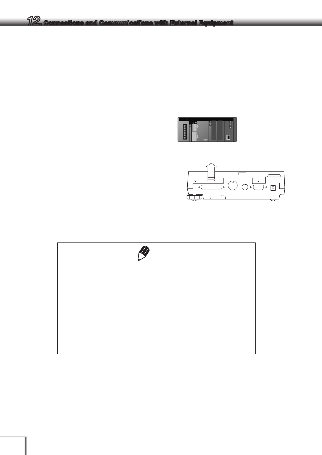
12. Connections and Communications with External Equipment
12.3 Connecting PLCs and Other Serial
Communications Equipment
It is possible to connect PLCs and other serial communication equipment to output weight values, perform
taring and calibration with special commands, and read and write setting values. Connect the equipment
to the balance in accordance with the following procedures in this event.
1 Switch off the power to the balance and other
equipment.
PLCs and other serial communication
equipment
2 Firmly connect the [RS232C] connector on the
rear of the balance to the communication
connector on the equipment with the use of a
special cable prepared by the user.
* See [Cable Connections (RS232C)] (P.79).
Cables to be prepared by the user
3 Switch on the power to the balance.
4 Switch on the power to the equipment.
Rear of the balance
5 Align the Communication settings on the balance to the settings on the equipment.
Notes
Procedures for confirming operations for the serial communications
equipment connected
There are many different types of communications specifications for serial
communications equipment depending on the manufacturer and the
equipment concerned. Read the instruction manual for the relevant
equipment first of all, and then check operations in accordance with the
following procedures.
(1) Check the cable connection, (2) Check that the communication
conditions are in alignment, (3) Establish communications procedures, (4)
Check operations.
6 Either press [PRINT] on the balance or send and receive a command from the equipment to check
whether the weight value has been correctly input and output.
78
Page 93

12. Connections and Communications with External Equipment
12.4 Cable Connections (RS232C)
12.4.1
(1) D-sub9 pin (Cross connection = Reverse
Connecting the Cable
!
• The cable must have the correct connections as shown in the diagram
below.
• Cables with the connections shown below and the special accessory
RS-232 cable are not guaranteed to operate properly for all types of
computers and devices.
connection)
Computer side Balance side
RXD 2 ————— 2 TXD
TXD 3 ————— 3 RXD
DTR 4 ————— 6 DSR
SG 5 ————— 7 SG
DSR 6 ————— 20 DTR
RTS 7 5 CTS
CTS 8 4 RTS
1
Caution
2
3
4
5
6
7
8
9
10
11
12
13
14
79
Page 94

12. Connections and Communications with External Equipment
12.4.2
The detailed information on the standard format for Shimadzu electronic balances (Menu item 77 , “EB
type”. Refer to 12.3.3) is given here.
(1) Basic format
Data Format
An example of data format of a negative value (-186.65g) with delimiter of C/R is shown.
The data length varies depending on attached information, unit expression and delimiter as explained
in (2).
Data length of this example: 12 bytes
Position 1 2 3 4 5 6 7 8 9 10 11 12
ASCII
code
data - 1 8 6 . 6 5 g C/R
Remarks
Position1: For a positive value, " " (space), and for a negative value, "-" is in this position.
Position 2 ~ 9: The absolute value. When the numerical value does not use all the 8
Position 10,11: One or two letters indicating the weighing unit. As shown in this example, the
Position 12: Code for delimiter.
2DH 20H 20H 31H 38H 36H 2EH 36H 35H 67H 20H 0DH
positions, the code for space is entered to each excessive position as shown
in this example.
code for space is entered at position No.11 if only one letter is used for the
unit.
(2) If data length is longer than standard
(i) Output with stability information
When outputting data with stability information (Refer to 12.2.3 (4)-(i)), either of the following
characters is added in front of Character No.1 in the example. Consequently, the data becomes 1
by te longer.
When stable: S
When unstable: U
(ii) When the delimiter “C/R+L/F” is selected (Menu item No. 96 . Refer to 12 . 3 .7.)
The delimiter information requires one more character. Therefore one more byte is added after
Position No.12 in the above example. Consequently, the data becomes 1 byte longer.
80
Page 95

12. Connections and Communications with External Equipment
(3) Data format in case of “oL” or “-oL” (Overload)
The below is the data format for “oL”.
Data length of this example: 12 bytes
Position 1 2 3 4 5 6 7 8 9 10 11 12
ASCII
code
Data O L C/R
For “-oL” (negative overload), Position 1 is replaced with “-” (minus, ASCII code: 2DH).
The following parts appearing in “(2) Information of additional bytes” also apply to (3).
(i) Output with stability information
(ii) When the delimiter “C/R+L/F” is selected, (Menu item No 96 , Refer to 12.3.7.)
20H 20H 20H 20H 20H 4FH 4CH 20H 20H 20H 20H 0DH
1
2
3
4
5
6
7
8
9
10
11
12
13
14
81
Page 96

12. Connections and Communications with External Equipment
12.4.3
Using Command Codes
Note
If communication conditions are incorrectly set, a communication error
message [ComErr] is displayed.
(1) Commands that end with a number, character, or symbol other than [=]: Transmit to the balance with
a delimiter for each command code.
Example 1: PRINT<CR>…The same operation as pressing the [PRINT] key
(2) Commands from (4) below which end in "="
Transmit to the balance with a delimiter added to the end after transmitting a number (including
decimal places in some cases) following one command code.
Example 2: TIME=1234<CR>
…12:34 is set as the current time.
Example 3: P.TARE=1.23<CR> (example of type of the second decimal place)
…1.23g is set as a Pretare value.
Example 4:) P.TARE=0.00<CR> (example of the second decimal place)
…Clears (cancels) the Pretare value.
Note
Number of digits, decimal point, position of decimal point of the numeral
transmitted succeeding to ‘=’ are the same as the case of setting the
numeric value using the AKB-301 Application Keyboard.
Use the same number of decimal places as in the gram-display. This
restriction does not apply to USER=, SOLID=, and LIQUID=.
Weighing capacity work instructions and display of arbitrary numbers on the balance can be
performed from a PC connected to the balance.
These commands will each display as "# = 2.56" and "# = 12.345.67" on the balance display. If the
balance operator presses the [PRINT] key after seeing these messages, the text strings '2-56<CR>'
and '12-345-67<CR>' will be output from the balance.
82
Page 97

12. Connections and Communications with External Equipment
(3) Echo back command
The balance again transmits the character strings of N pieces included between an echo back
command ‘{‘ or ’}’ and the delimiter. An unprocessed echo back command is not left in the receiving
buffer of the balance, N ≤ 30.
Example 5: {ABCDEFG12345<CR>
…After receiving this command, the balance outputs ABCDEFG12345<CR>.
When using the balance together with a printer, these text strings can be printed to the printer.
(Printing of arbitrary text strings)
Note
Only capital alphabets and a part of symbols (decimal point, symbol etc.)
can be used when printing with an electronic printer. A maximum of 15
characters per line.
(4) Command codes for Format EB type (menu item77
78
)
(i) Commands related to output
D01 Continuous output*
D03 Continuous output with stability information*
D05 Single output
D06 Auto Print setting (type of Auto Print is set separately)
D07 Single output with stability information***
D09 Release of continuous output and Auto Print
1
2
3
4
5
) [F-PrEEb]) and Format Old EB type (menu item
6
7
(The balance continuausly outputs
every about 80ms**)
8
9
(ii) Commands related to operation keys
POWER Equivalent to the [POWER] key.
Q Equivalent to the [POWER] key.
MENU Equivalent to the [CAL] key.
TAR E Equivalent to the [O/T] key.
T Equivalent to the [O/T] key.
UNIT Equivalent to the [UNIT] key.
PRINT Equivalent to the [PRINT] key.
POWER+ Equivalent to holding the [POWER] key
MENU+ Equivalent to holding the [MENU] key
UNI T+ Equivalent to holding the [UNIT] key
PRIN T+ Equivalent to holding the [PRINT] key
RECALC Equivalent to the [RECALC] key of the AKB-301 Application Keyboard.
C Equivalent to the [C] key of the AKB-301 Application Keyboard.
*Not applicable to a verified balance as a legal measuring instrument in using region
**Handshake is “OFF” or “Hardware”
***Using a verified balance as a legal measuring instrument: Only output at stable.
10
11
12
13
14
83
Page 98

12. Connections and Communications with External Equipment
(iii) Commands related to application measurement
PEAK Sets the Peak Hold mode.*
AZERO Sets the Auto Zero mode ON.*
INTERVAL Sets the Interval Timer mode.*
MEMORY Sets the Formulation mode.
M Immediately operates after setting the Formulation mode.
ADDON Sets the Add-on mode.
+ Immediately operates after setting the Add-on mode.
A Sets the Animal Weighing mode.*
ANIMAL Sets the Animal Weighing mode.*
R Releases the Application weighing mode.
(iv) Commands related to unit conversion
g Switches to “g” unit.
kg Registration of “kg” unit and switching
mg Registration of “mg” unit and switching.*
PERCENT Registration of “%” unit and switching.
% Sets 100% when display is in “%” unit.
G
PCS Registration of “PCS” unit and switching.
CT Registration of “carat” unit and switching.
MOM Registration of “momme” unit and switching.*
SD Registration of “solid density” unit and switching.
LD Registration of “liquid density” unit and switching.
CU Switches to “user” unit (Set the conversion coefficient beforehand.).
RSTUNIT Returns the default units.
g ← → % switching.
(v) Readout commands of set value
TAR G E T Readout of target set value.
LIMIT Readout of limit set value.
G.LO Readout of lower limit set value in Checkweighing Display 1.
G.UP Readout of upper limit set value in Checkweighing Display 1.
L.LO Readout of lower limit set value in Checkweighing Display 2.
L.UP Readout of upper limit set value in Checkweighing Display 2.
UW Readout of unit weight set value.
G/PCS Equivalent to g/PCS key.
CALW T Readout of external weights set value for span calibration.*
ACALT1 Readout of Clock-CAL time 1.
ACALT2 Readout of Clock-CAL time 2.
ACALT3 Readout of Clock-CAL time 3.
P.TA R E Readout of Pretare set value.*
ZRNG Readout of Zero Range set value.
USER Readout of user unit conversion coefficient.*
VOL Readout of reference weight set value.
DENSE Readout of surrounding liquid density set value.
I.T IME Readout of Interval Timer set value.*
*Not applicable to a verified balance as a legal measuring instrument in using region
84
Page 99

12. Connections and Communications with External Equipment
(vi) Commands for numeric value setting
CA LW T= Sets external weights value for span calibration.*
ACALT1= Sets Clock-CAL time 1.
ACALT2= Sets Clock-CAL time 2.
ACALT3= Sets Clock-CAL time 3.
P.TA R E = Sets Pretare value.*
ZRNG= Sets Zero Range value.
UW= Sets unit weight.
USER= Sets user unit conversion coefficient.*
VO L= Sets volume of reference weight.
DENSE= Sets surrounding liquid density.
I.TIME= Sets interval timer value.*
DAT E= Sets the date.
TIME= Sets the time.
TAR G E T= Sets the target value.
LIMIT= Sets the limit value.
L.LO= Sets the lower limit value of Checkweighing Display 1.
L.UP= Sets the upper limit value of Checkweighing Display 1.
G.LO= Sets the lower limit value of Checkweighing Display 2.
G.UP= Sets the upper limit value of Checkweighing Display 2.
PCS= Sets the arbitrary loading piece.
#= Corresponds to numeral keys of AKB-301 Application Keyboard.
ID= Sets ID.
PASSSET= Sets PCAL password.*
PASS= Inputs PCAL password.*
1
2
3
4
5
6
7
(vii) Commands of special functions
CAL Enters Span Calibration mode.
C18 Enters Span Calibration mode.
LOCK Sets menu lock.
RELEASE Releases menu lock.
TIME Readout of date and time.
RSTMN Menu reset.
{ Echo back.
} Echo back.
*Not applicable to a verified balance as a legal measuring instrument in using region
8
9
10
11
12
13
14
85
Page 100

12. Connections and Communications with External Equipment
(5) Compatible commands with Mettler Toledo® PR and SR Series Electronic Balances
S One time output at a stable state
SI Immediate one time output*
SIR Continuous output*
SR Continuous output at a stable state
T Taring after stabilized
TI Immediate taring*
Z Zero setting (same as immediate taring)*
(6) Compatible commands with Sartorius® IPS Series Electronic Balances
<ESC> P One time output
<ESC> T Taring
Note
<ESC> indicates escape code (1BH).
*Not applicable to a verified balance as a legal measuring instrument in using region
86
 Loading...