

Shimadzu TW Series, TX Series, TXB Series Service Manual

321-78011G
May 2010
Electronic Balances
TW/TX/TXB Series
Service Manual
Precision Balance

- i -
Table of Contents
1. Operations for Adjustment...........................................................................................................................1
1.1. ROM version information.......................................................................................................................................... 1
1.2. Entering the Service Mode ....................................................................................................................................... 1
1.3. Contents of Service Menu ........................................................................................................................................ 2
1.4. Service Mode Functions ........................................................................................................................................... 3
2. Disassembling and Assembling the Balance..........................................................................................5
2.1. TW/TX Series ............................................................................................................................................................... 5
2.1.1. Precautions........................................................................................................................................................... 5
2.1.2. Inspecting the Balance Interior (Removing the Case and Pan Support) ....................................................... 6
2.1.3. Replacing Components....................................................................................................................................... 7
2.2. TXB Series.................................................................................................................................................................. 18
2.2.1. Precautions.........................................................................................................................................................18
2.2.2. Inspecting the Balance Interior (Removing the Case and Pan Support) ..................................................... 19
2.2.3. Replacing Components..................................................................................................................................... 21
3. Checking the Electronic Board.................................................................................................................25
3.1. TW/TX Series ............................................................................................................................................................. 25
3.1.1. Main Board Assy (B2)........................................................................................................................................25
3.1.2. Analog Board Assy (B3).................................................................................................................................... 25
3.1.3. Power Board Assy (B4)..................................................................................................................................... 26
3.2. TXB Series.................................................................................................................................................................. 27
3.2.1. Power Board Assy ............................................................................................................................................. 27
3.2.2. Display Board Assy............................................................................................................................................ 27
3.2.3. Analog Board Assy ............................................................................................................................................ 28
4. Hardware Adjustment.................................................................................................................................29
4.1. TW/TX Series ............................................................................................................................................................. 29
4.1.1. Adjusting the Height of the Detector Assy (U11).............................................................................................29
4.1.2. Adjusting the Tilt Error........................................................................................................................................30
4.1.3. Adjusting the Cornerload Error ......................................................................................................................... 31
4.2. TXB Series.................................................................................................................................................................. 32
4.2.1. Adjusting ZERO balance of load cell ...............................................................................................................33
4.2.2. Adjusting the Corner load Error ........................................................................................................................ 34
5. Software Adjustment...................................................................................................................................35
5.1. EEPROM Initialization.............................................................................................................................................. 35
5.2. Model Selection.........................................................................................................................................................35
5.3. Setting Information Lock ........................................................................................................................................37
5.3.1. Releasing the Setting Information Lock...........................................................................................................37
5.3.2. Setting the Setting Information Lock ................................................................................................................ 37
5.4. Inputting Reference Weight Values for Linearity Adjustment ........................................................................38
5.5. Linearity Adjustment................................................................................................................................................ 39
5.6. Calibration of internal weight ( PCAL ) (Only TW series)................................................................................. 39

- ii -
5.7.
Sensitivity Calibration by External weight .......................................................................................................... 40
5.8. Sensitivity Calibration by internal weight (Only TW series)............................................................................41
5.9. Weight loader check ( Only TW series )...............................................................................................................42
6. EEPROM........................................................................................................................................................43
6.1. PRINT Operations..................................................................................................................................................... 43
6.2. Data Edit (EDIT) Operations ................................................................................................................................... 44
6.3. Backup (BKUP) Operations ...................................................................................................................................44
6.4. Download (RESTR) Operations............................................................................................................................. 44
6.5. All Initialization (INIT) Operations.......................................................................................................................... 45
6.6. EEPROM data editing software............................................................................................................................. 45
7. Updating the Program.................................................................................................................................47
7.1. Programming Tools .................................................................................................................................................47
7.2. Programming............................................................................................................................................................. 47
7.2.1. Downloading the Program to the Tool.............................................................................................................. 47
7.2.2. Preparing the Tool .............................................................................................................................................. 51
7.2.3. Programming...................................................................................................................................................... 52
8. Performance Inspection.............................................................................................................................54
8.1. Reproducibility..........................................................................................................................................................54
8.2. Cornerload Error.......................................................................................................................................................54
8.3. Linearity ...................................................................................................................................................................... 54
8.4. Tilt Error ...................................................................................................................................................................... 54
9. Problems and Solutions.............................................................................................................................56
9.1. General Problem Solutions .................................................................................................................................... 56
9.2. Error Display.............................................................................................................................................................. 57
9.2.1. User Mode Errors............................................................................................................................................... 57
9.2.2. Service Mode Errors..........................................................................................................................................58
9.2.3. Self check when power is turned on ................................................................................................................ 58
10. Troubleshooting.......................................................................................................................................59
10.1. Display Won't Appear..........................................................................................................................................59
10.2. Display Not Showing Correctly......................................................................................................................... 59
10.3. Key Operation Does Not Work.......................................................................................................................... 60
10.4. Poor Reproducibility............................................................................................................................................61
10.5. "ERR H" Is Displayed .......................................................................................................................................... 62
10.6. When Power is Switched On, Display Stops at "CHE 5" or “Software Version” ................................... 63
10.7. When Power is Switched On, Display Stops at "CHE 0".............................................................................64
10.8. Trouble of Weight Loader................................................................................................................................... 65
11. Components List ......................................................................................................................................66
11.1. TW/TWC,TX/TXC series ...................................................................................................................................... 66

- iii -
11.1 .1.
TW/TWC,TX/TXC exploded view .................................................................................................................... 66
11.1 .2. TX/TXC series dedicated jigs ...........................................................................................................................76
11.2. TXB Series ............................................................................................................................................................. 77
11.2 .1. TXB exploded view............................................................................................................................................77
11.2 .2. TXB Series Maintenance Parts ........................................................................................................................ 78
11.2 .3. TXB series dedicated jigs..................................................................................................................................79
11.3. TW/TX/TXB Series Shared Jigs and Tools ..................................................................................................... 79
- 1 -
1. Operations for Adjustment
For the general operations method, see the User's Manual for the TW/TX/TXB Series.
1.1. ROM version information
TX ROM ver. Ver
TX only (except TXC623) Ver 1.XX.XX.XX
TW/TX-L all model Ver 2.XX.XX.XX
TW/TX-N
(*1)
and TW/TX-L all
model
Ver 3.XX.XX.XX
*1: for Japan only
1.2. Entering the Service Mode
Move from user mode to service mode as follows.
(1) In the user mode mass display state, keep pressing (3-5sec.) [BREAK] and [PRINT] keys.
(2) Release the keys.
(3) Press down on the [CAL] and [->O/T<-] keys.
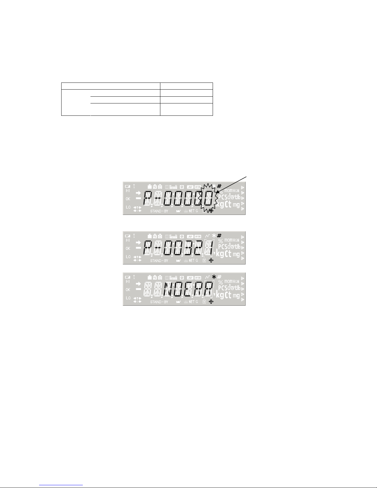
(4) The password input display appears. Flashing
Use the arrow keys to input numbers.
Input 00321 as the maintenance mode password, and press the [MENU/Enter] key.
(5) When the password is approved, the service mode opens.
Alternately, you can enter service mode by inputting the maintenance mode command "@SVC=321" from
the PC.
- 2 -
TYPEDisplay
SHIPDisplay
SoftwareVersion
ADDisplay WAD ※
TAD ※
OAD ※
LAD ※
WG ※
CR ※
SelectType Type list
SetShipment Japan
SI
EXP
ASIA
TA
SirialNO.Input UP5divInput
DOWN5divInput
OEMSetting ON
WeightInput
Min Input
Lock Setting ON ※
NVRAM "PRINT" OUTPUTOFRAMDATA
"EDIT" RAMDATAEDIT
"BK.UP" EEPROM->FLASH
"RESTR" FLASH->EEPROM
"INIT" INITIALIZATIONOFRAMDATA
END
Ok?
Ok?
EditRun
Input
Input
Input
Input
Linear AdjustRun
SettingWeight Input
Ok?
(MaintenanceMode) ※MarkingmeangoingbucktoMeasureMode
AD
ErrorLog
AfterAgeing
Span(ppm/C)
AfterAgeing
ZERODrift(g/C)
BeforeAgeing
Span(ppm/C)
BeforeAgeing
ZERODrift(g/C)
Ok?
OnlyTXBSeries
WeightLoader HOMEPOSITION
LOAD,UNLOAD
OnlyTWSeries
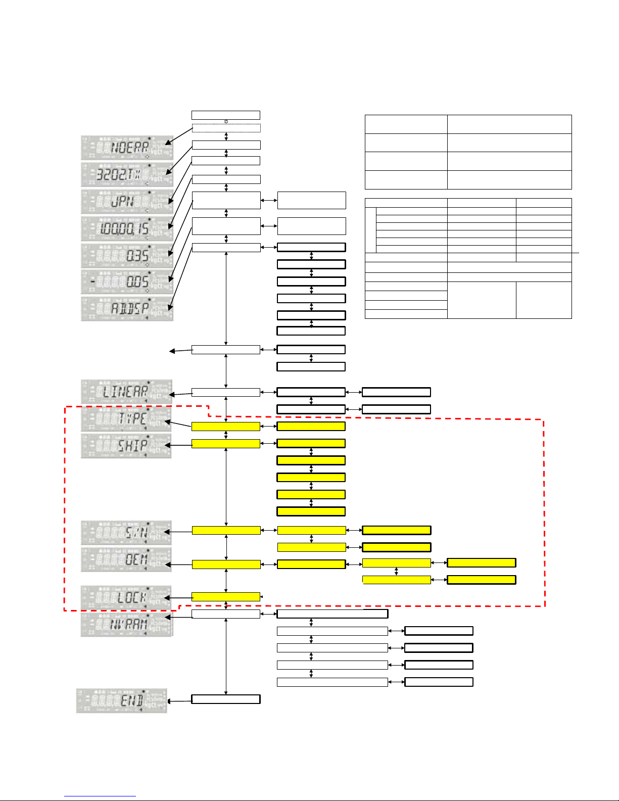
1.3. Contents of Service Menu
The service mode configuration (menu configuration diagram) is shown below.
Display example
[Normal Range (guideline)]
Span after aging
ppm/ °C
0 to ± 3 (TW/TX)
0 to ± 5 (TXB)
Span before aging
ppm/ °C
0 to ± 20 (TW/TX)
0 to ± 80 (TXB)
Zero after aging
g/ °C
0.000 to ± 0.200 (TW/TX/TXB)
Zero before aging
g/ °C
0.000 to ± 0.500 (TW/TX/TXB)
Zero Span
old TXC
1,100,000-2,000,000 2,000,000
common TWC/TXC
200,000-800,000 3,000,000(600ct)
old TX small pan
700,000-1,400,000 2,000,000
common TW/TX small
200,000-1,100,000 2,700,000(420g)
old TX Large pan
500,000-900,000 1,650,000
Wad
(
TW.TX
)
common TW/TX large
200,000-1,100,000 2,700,000(4200g)
WAD (TXB)
60,000 - 80,000 200,000
TAD (TW/TX)(10-30℃)
26,000 – 40,000
TAD (TXB) 15,000 – 29,000
OAD
LAD
WG
CR
±10.000
(g)
Weighing
capacity
(g)
← If no error has occurred,
"NOERR" is displayed.
Press the → key to display
the last five errors recorded
in the log, in order of
occurrence.
Not appear when [LOCK] is ON.
- 3 -
Items in the figure framed in thick lines denote execution items, while those framed in thin lines denote menu
items.
Shaded items are not displayed when the setting information lock is on. Use the arrow keys to move between
items.
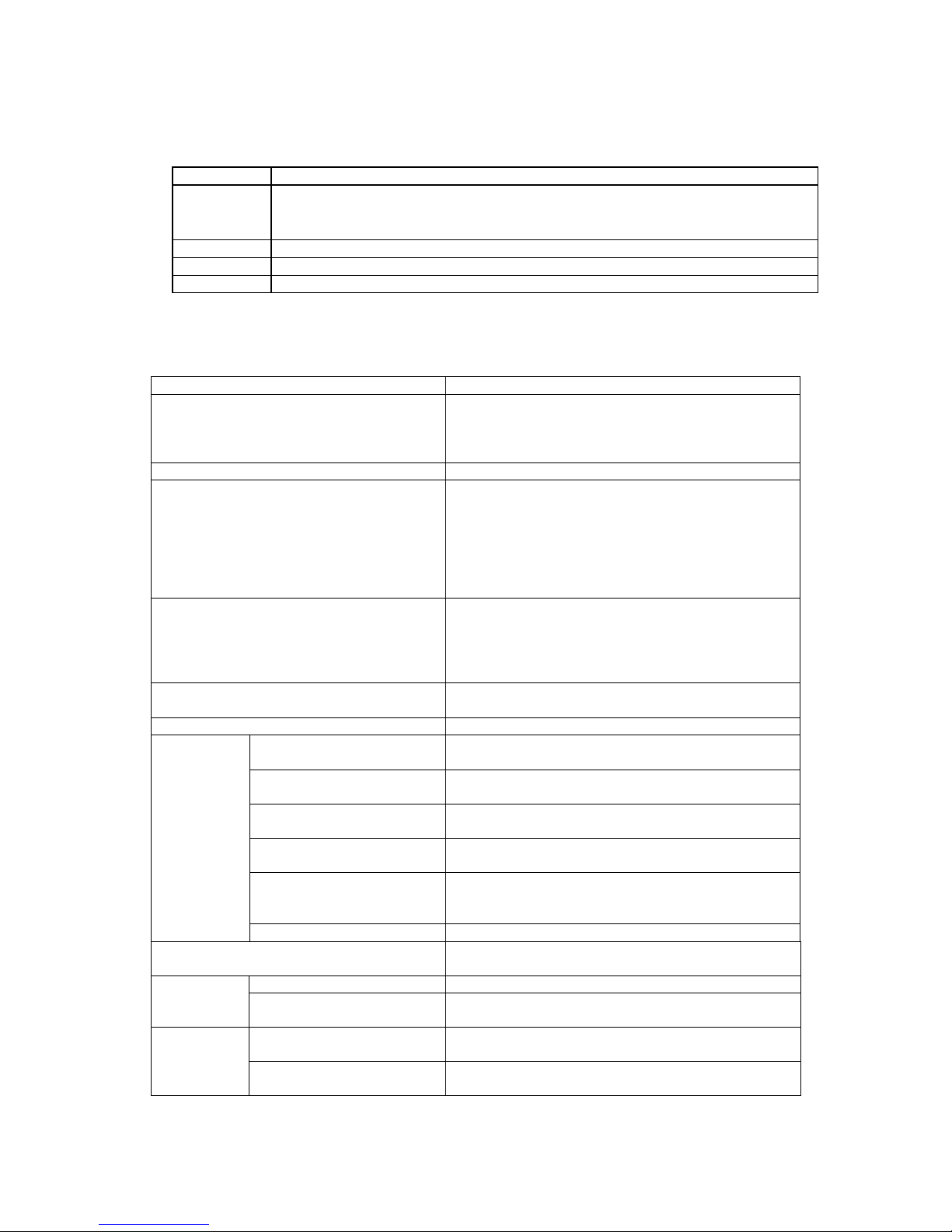
Key Explanation
→
Move to an item in a subordinate menu. If the menu item to the left of the arrow has no asterisk mark and is also
shaded, pressing the Enter key on that item opens a subordinate menu item. (In other words, if the higher menu
accepts the Enter key even if it has no enable/disable switch, pressing the Enter key opens the subordinate menu.)
To open the menu from the mass display state, use the MENU key instead of the → key.
←
Return to the item in the higher menu.
↓
Move to items in order.
↑
Move to items in reverse order.
* For the release method of setting information lock, see " 5.3.1 Releasing the Setting Information Lock".
1.4. Service Mode Functions
Service mode functions are shown below.
Function Outline
Error display Displays error codes for errors that have occurred in user
mode.
If no errors have occurred when service mode is opened,
the error display does not appear.
Model name display Displays the model name setting.
Destination display Displays the destination setting.
Ex.: JPN = Japan
SI = Countries and regions that recognize SI units
only
EXP = Overseas (excluding Southeast Asia)
ASIA = Southeast Asia
TA = Type Approval
Software Ver. display Displays the currently mounted software version.
Ex.: 1.00, ##, XX
In principle, 1.00 is the version number for hardware changes
Next, ## is the version number for manuals and other documentation
changes
Finally, XX is the version number for bug fixes and other minor changes
Span temperature coefficient display Displays the span temperature coefficient for before and
after aging.
Zero drift display Displays the amount of zero drift before and after aging.
AD value
display
Mass data (WAD) display Displays mass data as received from AD converter. (Data
subjected to smoothing)
Temperature data (TAD)
display
Digitally displays voltage of temperature sensor mounted
on UniBloc magnet or load cell.
Temperature-corrected mass
data (OAD) display
Displays WAD mass data subjected to temperature
correction. (Data subjected to smoothing)
Linear-corrected mass data
(LAD) display
Displays OAD mass data subjected to linearity correction.
Absolute load (WG) display Displays mass values shown in g units that are subjected
to all correction processing. Displays mass values not
subjected to zero setting or tare weight.
Creep (CR) display (TXB only) Displays WG mass data subjected to creep correction.
Sensitivity calibration Executes sensitivity calibration using the same operation
as user mode.
Return to initial position Internal weight loader system returns to initial position. Weight
Loader check
(Only TW)
Load and Unload Internal weight is loaded or unloaded to UNIT ASSY.
Linearity adjustment Executes the adjustment operation for calculation of the
linearity correction coefficient.
Linearity
adjustment
Weight value input for linearity
adjustment
Inputs the reference weight value used for linearity
adjustment.
- 4 -
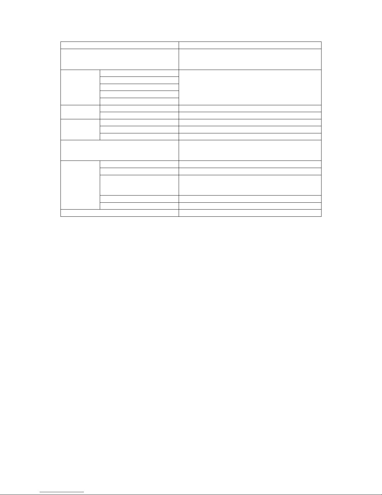
Function General
Model selection Selection of the model name automatically sets the basic
information for weighing capacity, minimum display, and
reference mass for adjustment.
Unit for Japan
SI unit
Overseas unit
Unit for Asia
Shipping
settings
Type Approval
Set the units users can use, depending on shipping
destination.
Initial setting = Unit for Japan
Top 5 digits Input the top 5 digits of serial No. Serial No.
input
Bottom 5 digits Input the bottom 5 digits of serial No.
On Sets to OEM model.
Weighing capacity Changes the weighing capacity.
OEM
Minimum display Changes the minimum display.
Setting information lock (error check) Prevents changes to the model, OEM, shipping, and S/N
settings. When the lock is active, all error checks are
enabled.
Data print Outputs data saved in EEPROM to a dedicated printer.
Data edit Edits data saved in EEPROM on balance display unit.
Backup Of the data saved in EEPROM, backs up temperature
correction coefficient, linearity correction coefficient, and
model setting status data to a Flash memory.
Download Writes to EEPROM the data backed up on Flash memory.
NVRAM
All initialize Initializes all data saved in EEPROM.
END Ends service mode.
- 5 -
2. Disassembling and Assembling the Balance
2.1. TW/TX Series
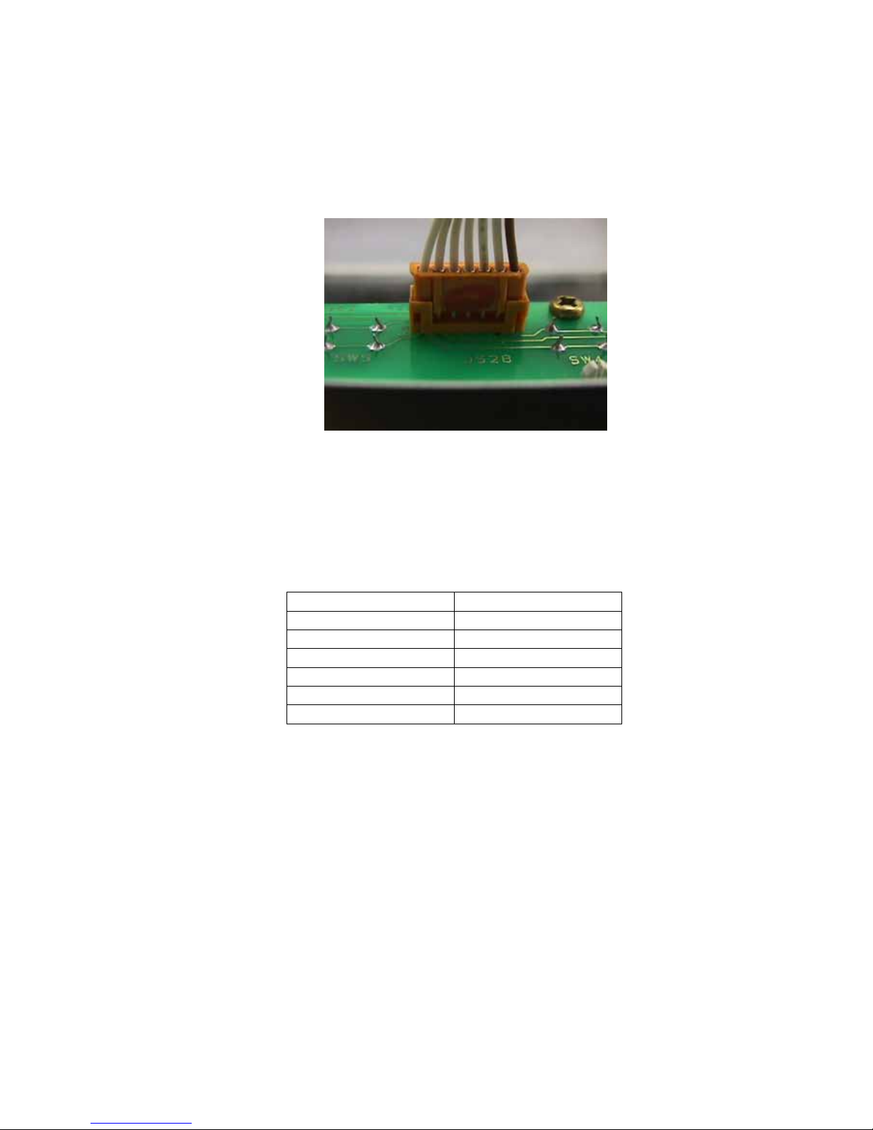
2.1.1. Precautions
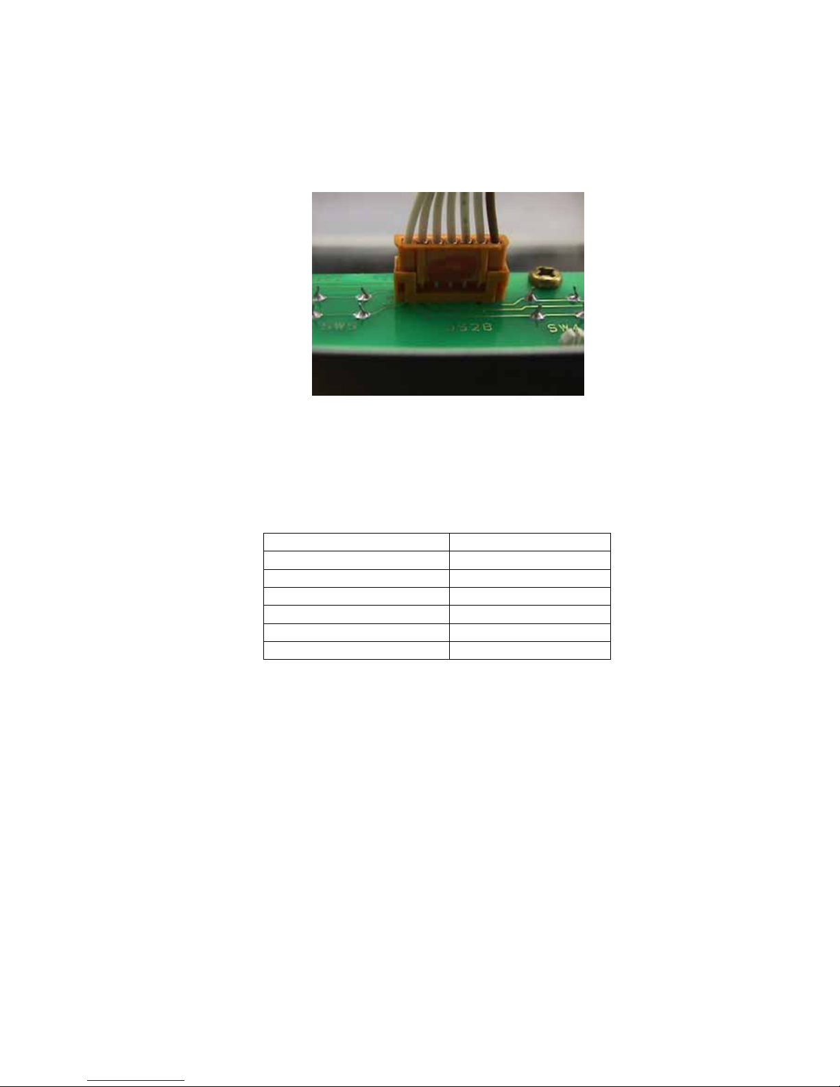
1) Pull the connector straight out when disconnecting. Never pull it out at a bent angle.
* Pulling out at a bent angle could bend the terminal pins, making it difficult to re-insert the
connector.
Fig. 1
2) For disassembly and assembly of the unit Assy TX(1), first insert the OPF positioning pin (J1) as far as the
line set in the lever fixing hole on the OPF surface.
* Lift slightly on the lever Assy (U7) to insert the pin. Be careful not to scratch the elastic support.
3) Use a controlled torque driver to tighten the screws to the torques shown in the table below.
Screw Torque [kgf-cm]
M2 1
M2.5 2.5
M3 pan head 9
M3 hexagonal socket head 15
M4 pan head 18
M4 hexagonal socket head 30

- 6 -
2.1.2. Inspecting the Balance Interior (Removing the Case and Pan Support)
[Disassembly]
1) Detach the AC adaptor, then:
[Carat/small pan only] Remove the pan (6), pan support (4), windbreak ring (7) (carat only), and sole plate
(8).
[Large pan only] Remove the pan (6), pan support cap (5), and sole plate (8).
2) [Carat/small pan only] Remove the knob (C10) on the inside of the ceiling glass set (C5), and slide the
ceiling glass set (C5) backward to remove.
3) Remove the P4 M4×12 screw (22) on the back side of the balance top surface, and pull up slightly on the
back side of the case Assy (3), so that it slides toward the front and separates from the base. (Fig. 2)
* In this condition, the main board Assy (B2), analog board Assy (B3), and power board Assy (B4)
can be inspected.
[Assembly]
1) Place the case Assy (3) over the base Assy (2) so that it catches on the front hooks, and tighten using the
P4 M4×12 screw (22) on the back side of the balance top surface.
2) [Carat/small pan only] Slide in the ceiling glass set (C5) from the back of the designated grooves, and
attach the inner knob (C10).
3) [Carat/small pan only] Mount the sole plate (8), windbreak ring (7) (carat only), pan support (4) and pan (6).
[Large pan only] Mount the sole plate (8), cap (5), and pan (6). (Fig. 2)
Fig. 2
4) Use the two front caster Assys (B6) to adjust the level of the balance so that the air bubbles in the level
come to the center of the framed area.
5) [Large pan only] Lower the two rear caster Assys (B6) until they contact the ground.
6) Attach the AC adaptor to the balance, and check the balance operation.
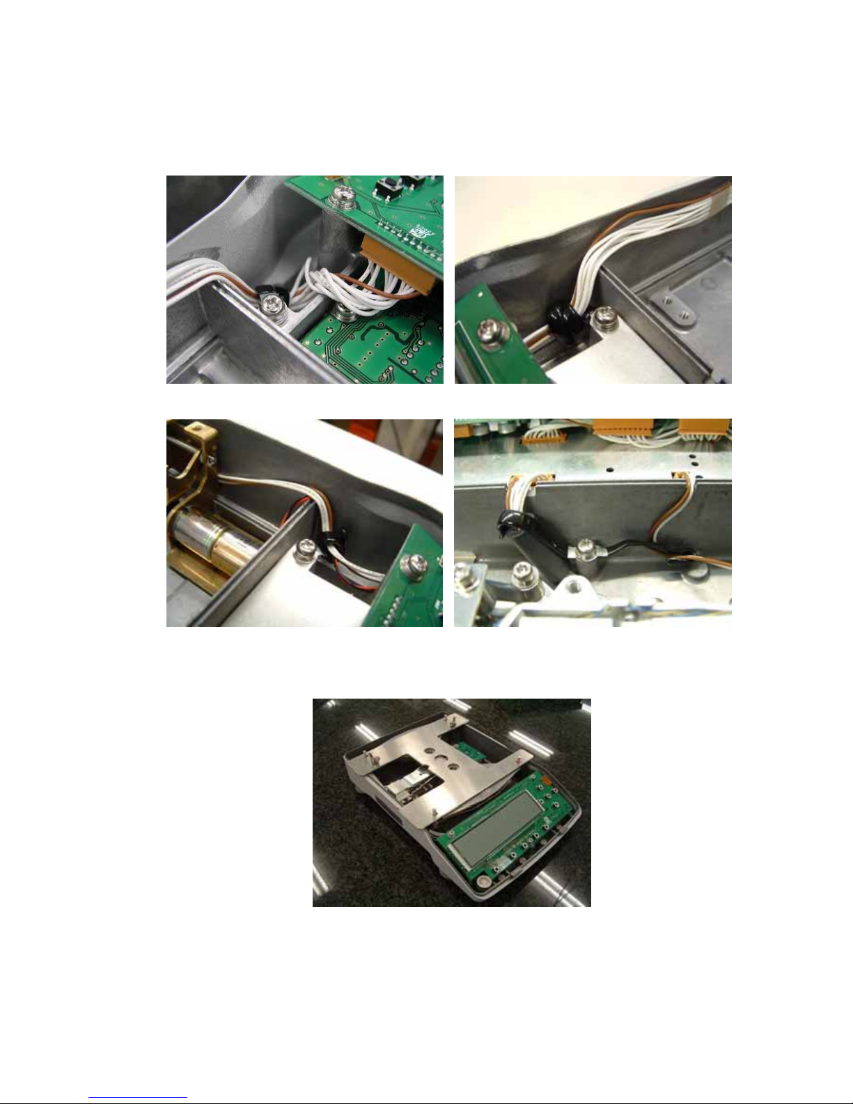
* When placing the case Assy (3) in position, be careful not to pinch the ILS 10S-10S-300 cable or
ILS 11S-11S-440(B9) connected between Main board Assys(B2) and Power Board Assys
(Fig. 3)(Including later procedure after this, photo A shows old TX and B shows TW/TX common.)
- 7 -
Fig. 3-A Fig. 3-B
2.1.3. Replacing Components
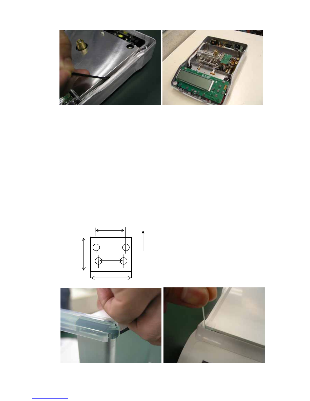
2.1.3.1. Replacing the Front Glass (C8)
1) Detach the AC adaptor, and remove the pan (6), pan support (4), windbreak ring (7) (carat only), and sole
plate (8).
2) Remove the knobs (C10) on the inside of the ceiling glass set (C5) and side glass sets (C6, C7) and slide
the ceiling glass set (C5) and side glass sets (C6, C7) backward to remove.
3) Remove the knobs (C10) in two locations on the front.
4) Tilt the rear surface of the case roof cover
(C4) and remove it. (Fig. 4)
5) Loosen the P4 M4×12 screw (22) holding the case roof (C3), and remove the case roof (C3).
6) Position the front glass (C8) on the back of the case (C1) front groove, and pull upward to remove the front
glass (C8). (Fig. 5)
7) Follow steps 1) to 6) in reverse to attach the new front glass (C8).
C
Top
A Length: A < B,C > D
D
B
Fig. 4 Fig. 5
- 8 -
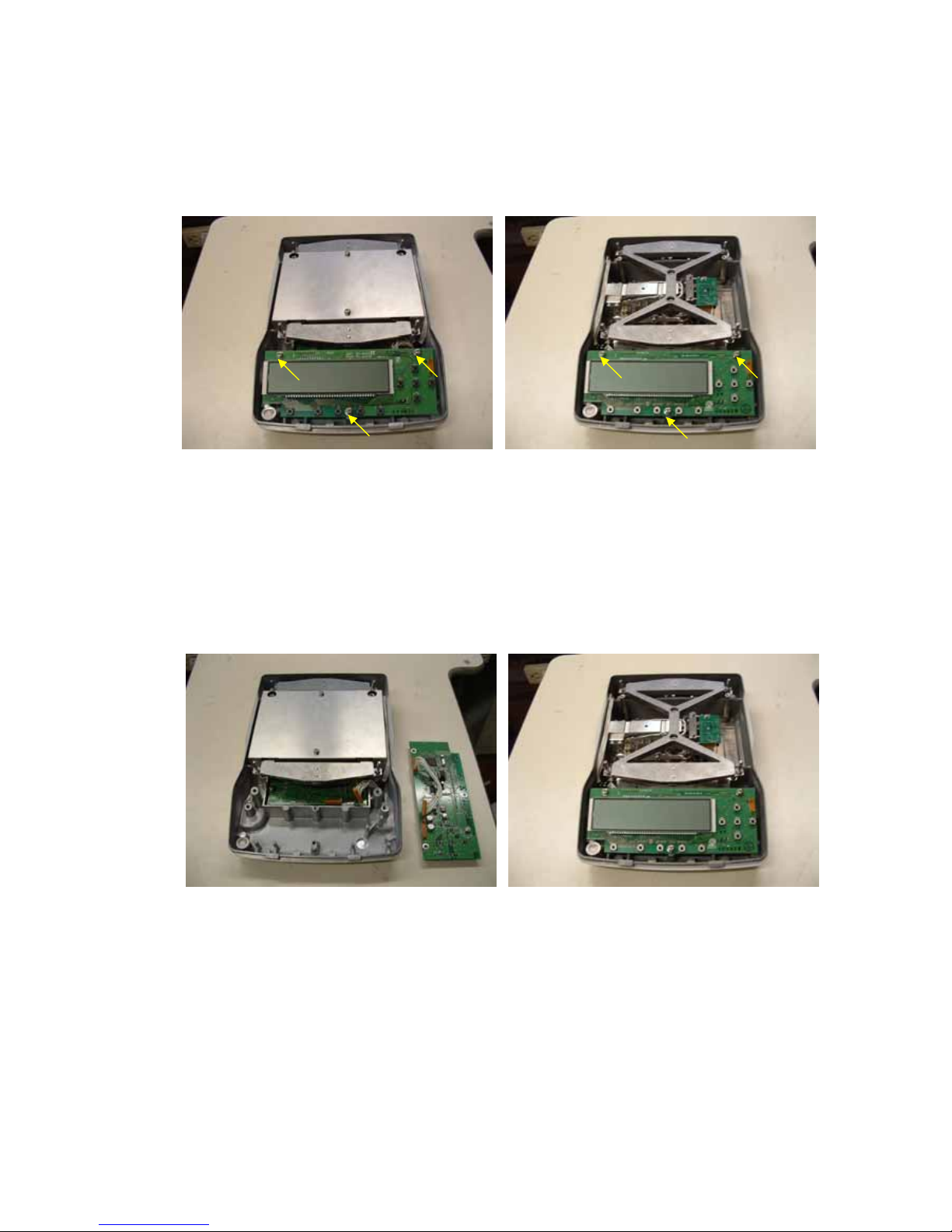
2.1.3.2. Replacing the Main Board Assy (B2)
1) Use the procedure in " 2.1.2 Inspecting the Balance Interior (Removing the Case and Pan Support)" to
remove as far as the case Assy (3).
2) Remove the three P4 M4×8 screws (B22) fixing the main board Assy (B2) in place. (Fig.6)
Fig.6-A Fig.6-B
3) Disconnect the J2,J3 and J4 connectors that are connected to the main board Assy (B2).
4) Place the main board Assy (B2) in a location on the right side of the balance that is free of dirt and static
electricity. (Fig. 7)
5) Remove the EEPROM located on the back side the main board Assy (B2) from the socket, taking care to
avoid damaging the EEPROM feet.
6) Mount the EEPROM on the new main board Assy (B2).
7) Follow steps 1) to 3) in reverse to attach the new main board Assy (B2).
Fig.7-A Fig.7-B
- 9 -
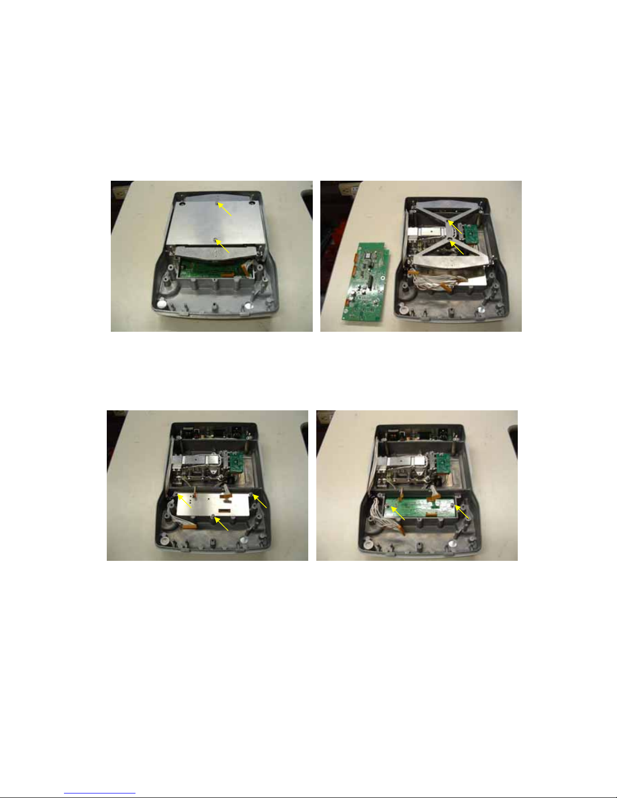
2.1.3.3. Replacing the Analog Board Assy (B3)
1) Use the same procedure as steps 1) to 3) in " 2.1.3.2 Replacing the Main Board Assy (B2)" to remove as far
as the main board Assy (B2).
2) [Large pan only] Loosen the two P4 M4×8 screw (22), and remove the large unit cover (9). (Fig.8)
3) [Large pan only] Insert the OPF positioning pin (J1) as far as the line set in the lever fixing hole on the OPF
surface.
4) [Large pan only] Loosen the two P4 M4×14 bolt (23), and remove the large pan support Assy (4). (Fig.9)
Fig.8 Fig.9
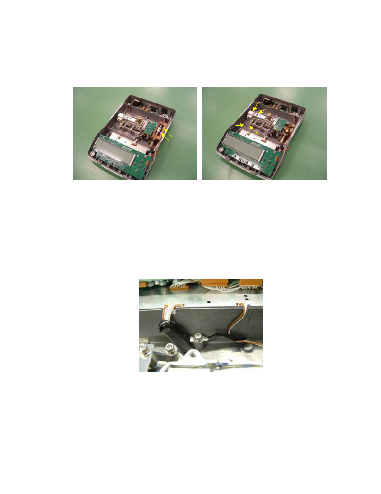
5) Disconnect the J1,J2 and J3 connectors that are connected to the analog board Assy (B3) and
loosen and remove the three P4 M4×8 screws (B22) fixing the cover plate,analog (13) . (Fig. 10)
6) Loosen and remove the two P4 M4×8 screws (B22) fixing the analog board Assy (B3) in place. (Fig. 11)
Fig.10 Fig.11
- 10 -
7) Follow steps 1) to 6) in reverse to attach the new analog board Assy (B3).
* During assembly, use the CS-5 clip (B26) to securely hold the cables for Main board Assy(B2),the
weight loader Assy(27) (TW only) and Unit assy,TX(1) downward so that the large pan support
Assy (4) and the cables do not contact. (Fig. 12)
Fig.12-A Fig.12-B1
Fig.12-B2 Fig.12-B3
*Attach pan support Assy (4) using Unit assy locating jig(J2) (Fig.13)
Fig.13
- 11 -
2.1.3.4. Replacing the Power Board Assy (B4)
1) Use the procedure in " 2.1.2 Inspecting the Balance Interior (Removing the Case and Pan Support)" to
remove as far as the case Assy (3).
2) [Large pan only] Loosen the two P4 M4×8 screw (22), and remove the large unit cover (9).
3) [Large pan only] Insert the OPF positioning pin (J1) as far as the line set in the lever fixing hole on the OPF
surface.
4) [Large pan only] Loosen the two P4 M4×14 bolt (23), and remove the large pan support Assy (4).
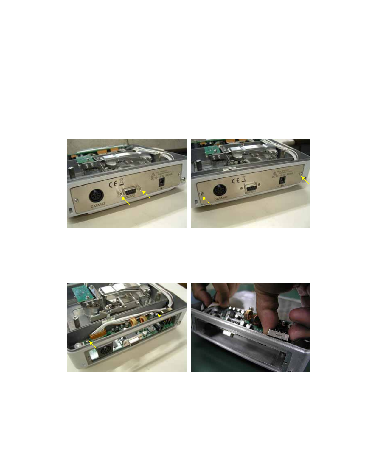
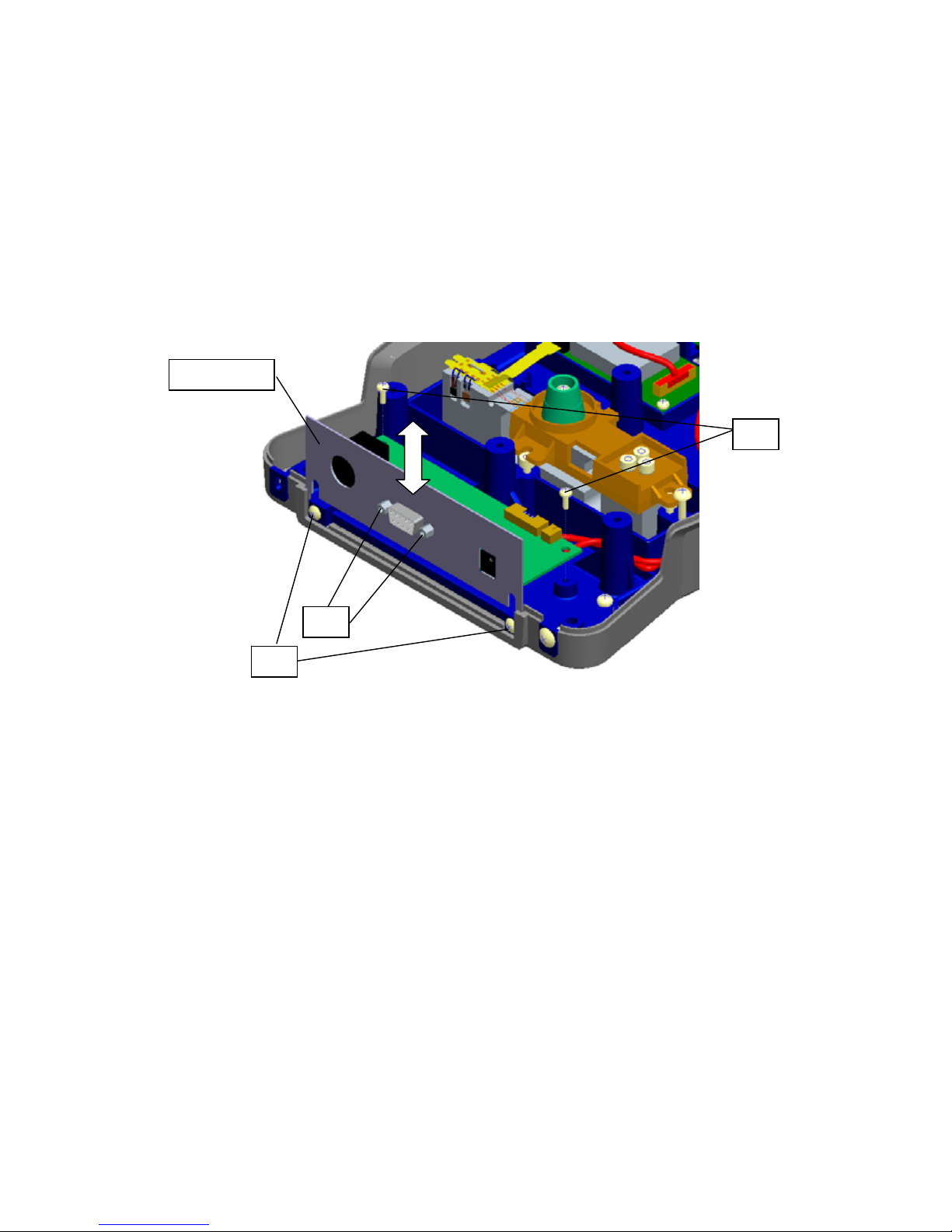
5) Remove the two screws,D-sub (B25) holding the power board Assy (B4) and I/F panel (B5) in place.
(Fig.14)
6) Loosen the two M3×6 button screws (B23) and remove the I/F panel (B5). (Fig. 15)
Fig.14 Fig.15
7) [Common design for TW/TX only] Open the cable clamp for ILS 11S-11S-440(B9).
8) Loosen the two P4 M4×8 screws (B22) fixing the power board Assy (B4) in place, and remove together
with the CS-5 clip (B26). (Fig. 16)
* The power board Assy (B4) can be removed by pulling upward at an angle, as shown in Fig. 17.
Fig.16 Fig.17
- 12 -
9) Disconnect the J4 connector that is connected to the power board Assy (B4).
10) Follow steps 1) to 9) in reverse to attach the new power board Assy (B4).
* During assembly, use the cable clamp and the CS-5 clip (B26) to securely hold the cables for
Power board Assy(B4) downward so that the large pan support Assy (4) and the cables do not
contact. (Fig. 16 and 18)
Fig.18-A Fig.18-B
2.1.3.5. Replacing the Detector Assy (U11)
1) Use the procedure in " 2.1.2 Inspecting the Balance Interior (Removing the Case and Pan Support)" to
remove as far as the case Assy (3).
2) Loosen the P4 M4×8 screw (22), and remove the unit cover (9).
3) Insert the OPF positioning pin (J1) as far as the line set in the lever fixing hole on the OPF surface.
4) [Large pan only] Loosen the P4 M4×14 bolt (23), and remove the large pan support Assy (4).
5) Remove the soldering for the temperature sensor cable connected to the detector Assy (U11). (Fig. 19)
* TP1: Yellow wire, TP2: Blue wire
6) Disconnect the J25 connector for the ILS-7S-7S-130 cable (U19) that is connected to the detector Assy
(U11).
* When removing, be careful not to touch the lever Assy (U7) and scratch the elastic support.
7) Loosen and remove the P3 M3×10 socket head bolt (U53) holding the detector Assy (U11) in place. (Fig.
20)
Fig.19 Fig.20
- 13 -
8) Follow steps 4) to 7) in reverse to attach the new detector Assy (U11).
9) Adjust the detector height by following " 4.1.1
Adjusting the Height of the Detector Assy (U11)".
10) Follow steps 1) to 4) in reverse to restore the original status.
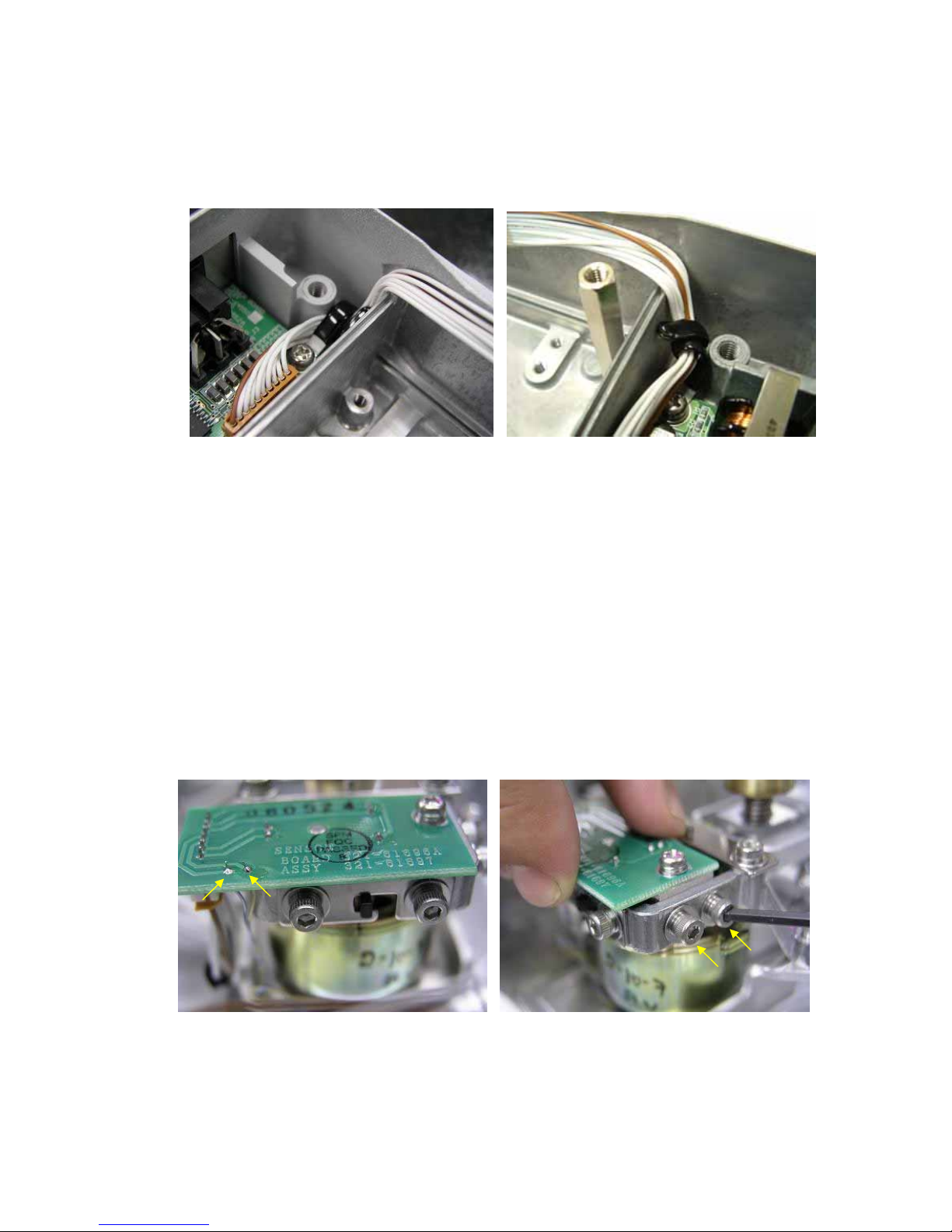
* Clamp to securely hold cable,ILS 7S-7S-130(U19) with short loose length so that the
Assy,Detector (U11) do not receive upward or downward force by it. (Fig. 21)
* [TW only] Clamp to securely hold cable,ILS 7S-7S-130(U19) and wires for the temp.sensor
outside of Magnet frame so that the weight lever for Unit assy,TX (1) and the cables do not
contact. (Fig. 22)
Fig.21 Fig.22
2.1.3.6. Replacing the TX Unit Assy (1)
1) Use the procedure in " 2.1.2 Inspecting the Balance Interior (Removing the Case and Pan Support)" to
remove as far as the case Assy (3).
2) [Non-CE only]Loosen the two P4 M4×8 screw (22), and remove the unit cover (9). (Fig.23)
3) Insert the OPF positioning pin (J1) as far as the line set in the lever fixing hole on the OPF surface.
4) [Large pan only] Loosen the two P4 M4×14 bolt (23), and remove the large pan support Assy (4). (Fig.24)
Fig.23 Fig.24
- 14 -
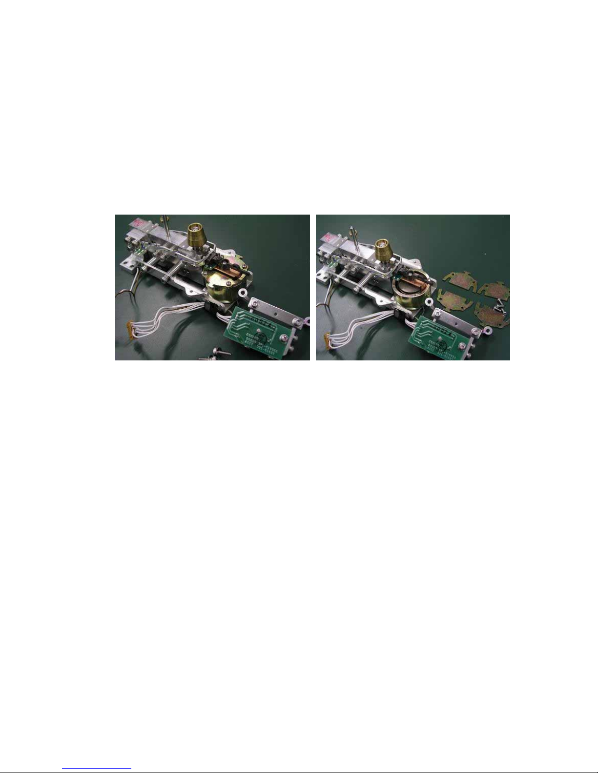
5) [TW only] Loosen the two P4 M3×6 screw (30), and remove the leaf supring,weight loaderr (29) and the
weight(28). (Fig.25)
6) Disconnect the J2 and J3 connectors that are connected to the analog board Assy (B3).
7) Loosen and remove the four P4 M4×14 socket head bolts (23) fixing the TX unit Assy (1) in place. (Fig. 26)
* When lifting up the TX unit Assy (1), do not grab the parallel guide or movable column.
Fig.25 Fig.26
8) Follow steps 4) to 7) in reverse to attach the new TX unit Assy (1).
* During assembly, use the CS-5 clip (B26) to securely hold the cables for Unit Assy,TX(1)
downward so that the large pan support Assy (4) and the cables do not contact. (Fig. 27)
9) Check tilt error and cornerload error by following " 4.1.2 Adjusting the Tilt Error" and " 4.1.3 Adjusting the
Cornerload Error". Adjust them,if they are out of torelance.
10) Follow steps 1) to 3) in reverse to restore the original status.
11) Input EEPROM data of attached with Unit assy.(Refer to 4.1) Address No. 004-05A (Temp. data)
Fig.27
- 15 -
2.1.3.7. Replacing the Weight loader Assy (27)
1) Use the procedure in " 2.1.3.6 Replacing the TX Unit Assy (1)" to remove the TX unit Assy (1).
2) Open the CS-5 clip for the cables of the weight loader assy(27) and disconnect the connector that are
connected to the main board Assy (B2)
3) Loosen and remove the three P4 M3×6 screws (30) fixing the weight loader Assy (27) in place. (Fig. 28)
4) Follow steps 2) to 3) in reverse to attach the new weight loader Assy (B3)
* During assembly, use the CS-5 clip (B26) to securely hold the cable for the weight loader
Assy(27) (TW only) downward so that the large pan support Assy (4) and the cables do not
contact. (Fig. 12)
Fig.28 Fig.29
5) Attach the AC adaptor and turn on the power of balance and enter the service mode and
select ”LD.ULD”and stop the arm weight loader on the lower position.
6) Insert Jig bloc,TW weight arm(J9) between the frame and the arm of weight loader Assy(27) to be the arm
on the level. (fig.30)
7) Tighten the four P4 M4×14 socket head bolts (23) temporarily fixing the TX unit Assy (1) in place.
8) Set location pin,weight loader(J8) on the dint of the arm of the weight loader Assy(27) and the weight
lever of the unit Assy,TX(1) and tighten the bolts for TX unit Assy(1) and screws for weight loader Assy(27)
(fig.31)
Fig.30 Fig.31
- 16 -
2.1.3.8. Replacing the Force Coil Assy (L1)
1) Use the procedure in " 2.1.3.6 Replacing the TX Unit Assy (1)" to remove the TX unit Assy (1).
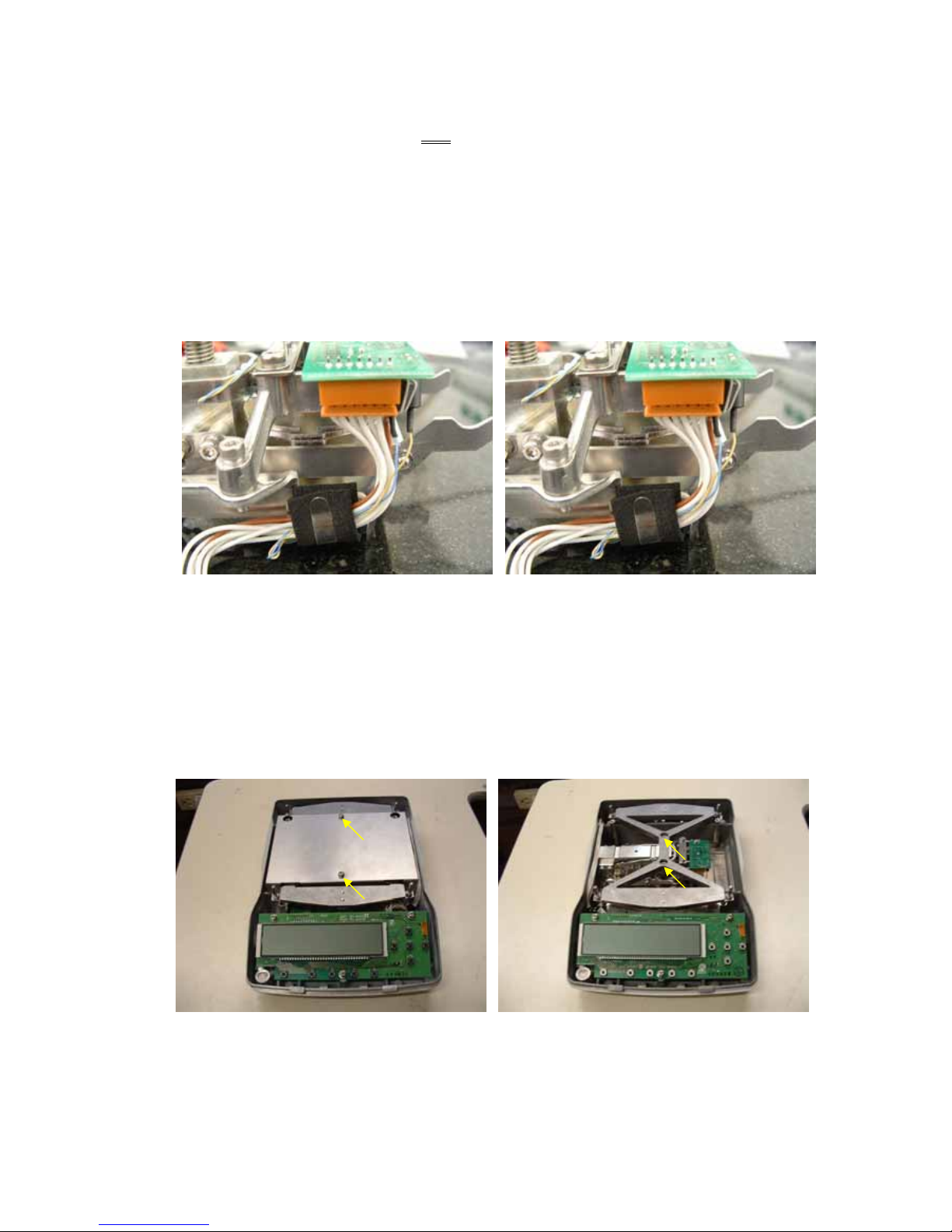
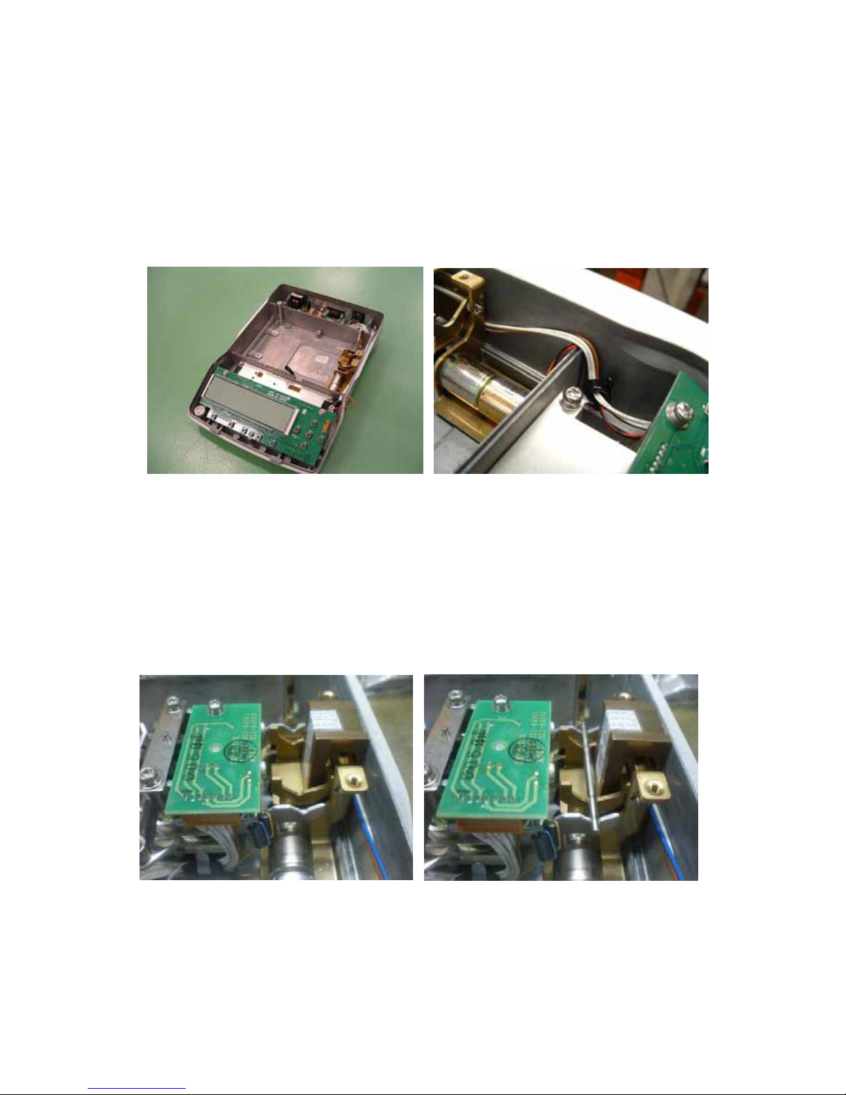
2) Remove the soldering on the lever Assy (U7) side of the two Pt-Ni bands (U17).
* Do not break or damage the PT-Ni bands.
3) Loosen and remove the two P3 M3×14 socket head bolts (U58) fixing the detector frame (U10) in place.
(Fig. 32)
4) Loosen the four M2.5×6 screws (U54) fixing the four magnet lids (U16) in place, and slide the magnet lids
(U16) in the horizontal direction to remove. (Fig. 33)
Fig. 32 Fig. 33
5) Remove the four P3 M3×14 socket head bolts (58) fixing the lever Assy (U7) in place, and remove the lever
Assy (U7) from above.
6) Remove the soldering from the twisted wire (L7) of the force coil Assy (L1) terminal board.
7) Loosen and remove the M2.5×6 screw (L5) and PB SPG M2.6 washer (L6) fixing the force coil Assy (L1) in
place.
8) Use an M2.5×6 screw (L5) to temporarily fix the new force coil Assy (L1) to the lever Assy (U7), and solder
the twisted wire (U7) to the force coil Assy (1). (Fig. 34)
* As viewed from lever Assy (U7) mounting side, Left side: Yellow wire, Right side: Blue wire
9) Insert the lever Assy (U7) from the top of the unit, and use four P3 M3×14 socket head bolts (58) to
temporarily fix it in place.
10) Pass the slit of the lever stopper (U15) attached to the detector frame (U10), and the pinhole of the stopper
plate (U14), through the lever Assy (U7), and use two P3 M3×14 socket head bolts (58) to temporarily fix
the frame detector (U7) in place.
11) Insert the gap setting shim (J3) between the lower edge of the lever shutter on the edge of the lever Assy
(U7) and the lower edge of the slit in the lever stopper (U15), for positioning, and use four P3 M3×14 socket
head bolts (58) to fix in place. (Fig. 35)
12) Remove the temporarily fixed detector frame (U7).
- 17 -
Fig. 34 Fig. 35
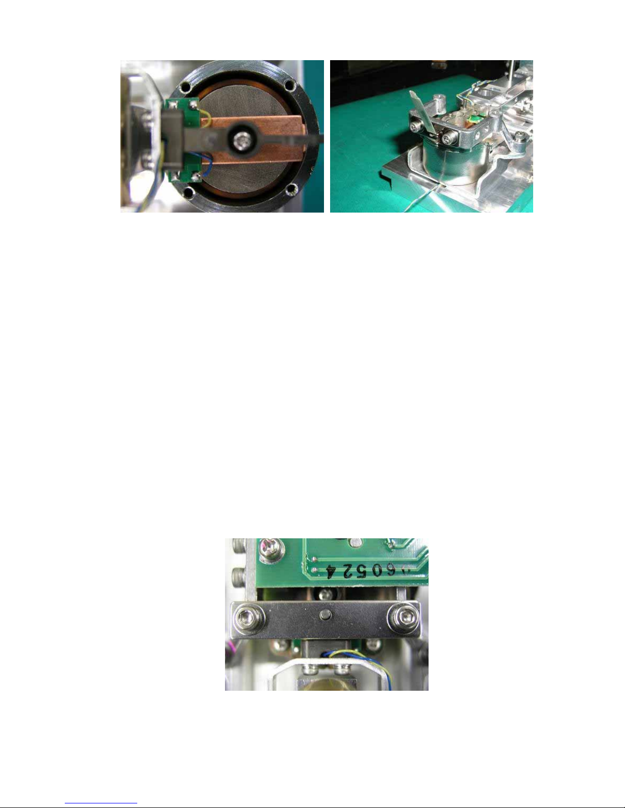
13) Looking at the TX unit Assy (1) from the top, tighten the force coil Assy (L1) at the position where the center
of the magnet Assy (U9) aligns with the center of the force coil Assy (L1).
14) Slide in and attach the four magnet lids (U16) from the horizontal direction and use four M2.5×6 screws
(U54) to tighten in place.
15) Again, pass the slit of the lever stopper (U15) attached to the detector frame (U10), and the pinhole of the
stopper plate (U14), through the lever Assy (U7), and use two P3 M3×14 socket head bolts (58) to tighten
the frame detector (U7) in place.
16) Solder the lever Assy (U7) side of the two Pt-Ni bands (U17).
* When soldering, do not twist or break the Pt-Ni bands.
17) Adjust the stopper plate (U14) to a position aligned with the center of the lever Assy (U7) pin, and use an
M3×6 socket head bolt (U57) and M3 washer (U56) to tighten.(Fig. 36)
18) Remove the OPF positioning pin (J1) from the TX unit Assy (1), then gently shake the TX unit Assy (1) to
check that the lever Assy (U7) moves smoothly up and down and that a clear sound is heard when it strikes
the lever stopper (U15). If it does, assembly of the TX unit Assy (1) is complete.
19) Follow steps 4) to 6) of " 2.1.3.6 Replacing the TX Unit Assy (1)" in reverse to attach the new TX unit Assy
(1).
20) Adjust tilt error and cornerload error by following " 4.1.2 Adjusting the Tilt Error" and " 4.1.3 Adjusting the
Cornerload Error".
21) Follow steps 1) to 3) of " 2.1.3.6 Replacing the TX Unit Assy (1)" in reverse to restore the original status.
Fig. 36
- 18 -
2.2. TXB Series
2.2.1. Precautions
1) Pull the connector straight out when disconnecting. Never pull it out at a bent angle.
* Pulling out at a bent angle could bend the terminal pins, making it difficult to re-insert the
connector.
Fig. 1
2) When handling the load cell Assy, be careful not to apply excessive force.
* The cell could be damaged.
3) Use a controlled torque driver to tighten the screws to the torques shown in the table below.
Screw Torque [kgf-cm]
M2 1
M2.5 2.5
M3 pan head 9
M3 hexagonal socket head 15
M4 pan head 18
M4 hexagonal socket head 30
- 19 -
2.2.2. Inspecting the Balance Interior (Removing the Case and Pan Support)
[Disassembly]
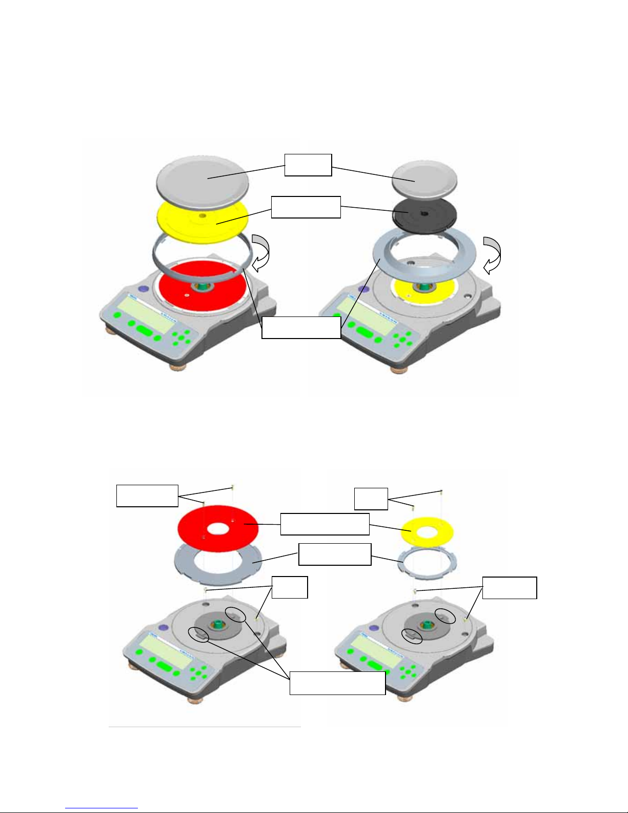
1) Detach the AC adaptor, and remove the pan (1), pan support (2), and windbreak ring (3). To remove the
windbreak ring (3), rotate it clockwise as viewed from above.
Fig. 1 Large Pan Model Fig. 2 Small Pan Model
2) Remove the two M4×10 pan head screws (21), and remove the metal plate (4) and ring spacer (5). Then,
remove the two M4×8 sems screws (22).
Fig. 3 Large Pan Model Fig. 4 Small Pan Model
(1) Pan
(2) Pan support
(3) Windbreak ring
(4) Metal plate
(5) Ring spacer
(21) M4×10
(22) M4×8
(21)
(22)
Ring spacer positioning
- 20 -
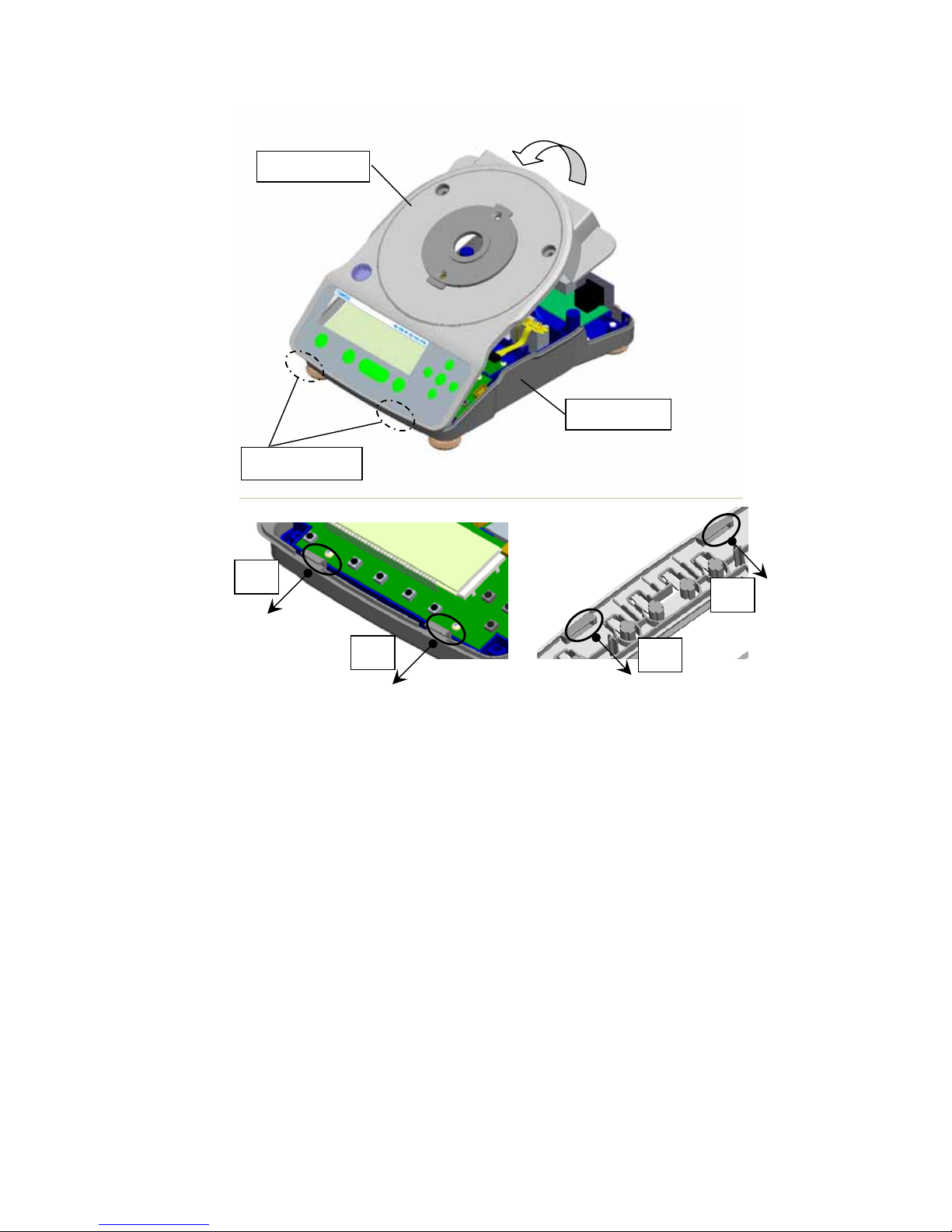
3) Lift up the upper case (6) from the back, and disengage from the hooks at the front of the lower case (7).
Fig. 5 Removing the Upper Case
* In this condition, the main board Assy (B1), analog board Assy (B2), and power board Assy (B3)
can be inspected.
[Assembly]
1) See Fig. 5 to insert the two slits on the front of the upper case (6) into the lower case (7) hooks, and
cover the back of the upper case (6) over the lower case (7).
2) Attach M4×8 sems screws (22) in two locations.
3) Mount the ring spacer (5) to align with the upper case (6) ring spacer positioning projection.
From above, align the metal plate (4) with the pan head screw hole on the ring spacer (5), and attach the
M4×10 pan head screw (21).
4) Attach the windbreak ring (3), pan support (2), and pan (1), in that order.
5) Use the two front level adjustment feet (8) to adjust the level of the balance so that the air bubbles in the
level come to the center of the framed area.
6) [Large pan only] Lower the two rear level adjustment feet (8) until they contact the ground.
7) Attach the AC adaptor to the balance, and check the balance operation.
(6) Upper case
Back: Two hooks
(7) Lower case
@A
@B
@A
@B
- 21 -
2.2.3. Replacing Components
2.2.3.1. Replacing the Main Board Assy (9)
1) Use the procedure in " 2.2.2 Inspecting the Balance Interior (Removing the Case and Pan Support)" to
remove as far as the upper case (6).
2) Disconnect the connector (C1) for cable 9-9 (13) and the connector (C2) for cable 10-10 (14) that are
connected to the main board Assy (9).
3) Remove the three P4 M4×8 screws (23) fixing the main board Assy (9) in place.
4) Place the main board (9) in a location that is free of dirt and static electricity.
5) Remove the EEPROM located on the back side the main board Assy (9) from the socket, taking care to
avoid damaging the EEPROM feet.
6) Mount the EEPROM on the new main board Assy (9).
7) Follow steps 1) to 3) in reverse to attach the new main board Assy (9).
2.2.3.2. Replacing the Analog Board Assy (10)
1) Use the procedure in " 2.2.2 Inspecting the Balance Interior (Removing the Case and Pan Support)" to
remove as far as the upper case Assy (6).
2) Disconnect the connector (C3) for cable 9-9 (13) that is connected to the analog board Assy (10).
3) Remove the cell Assy (12) flexible board (C4).
* Be careful not to damage the cell Assy.
4) Loosen and remove the four P4 M3×8 screws (23) fixing the analog board Assy (10) in place.
5) Follow steps 1) to 6) in reverse to attach the new analog board Assy (10).
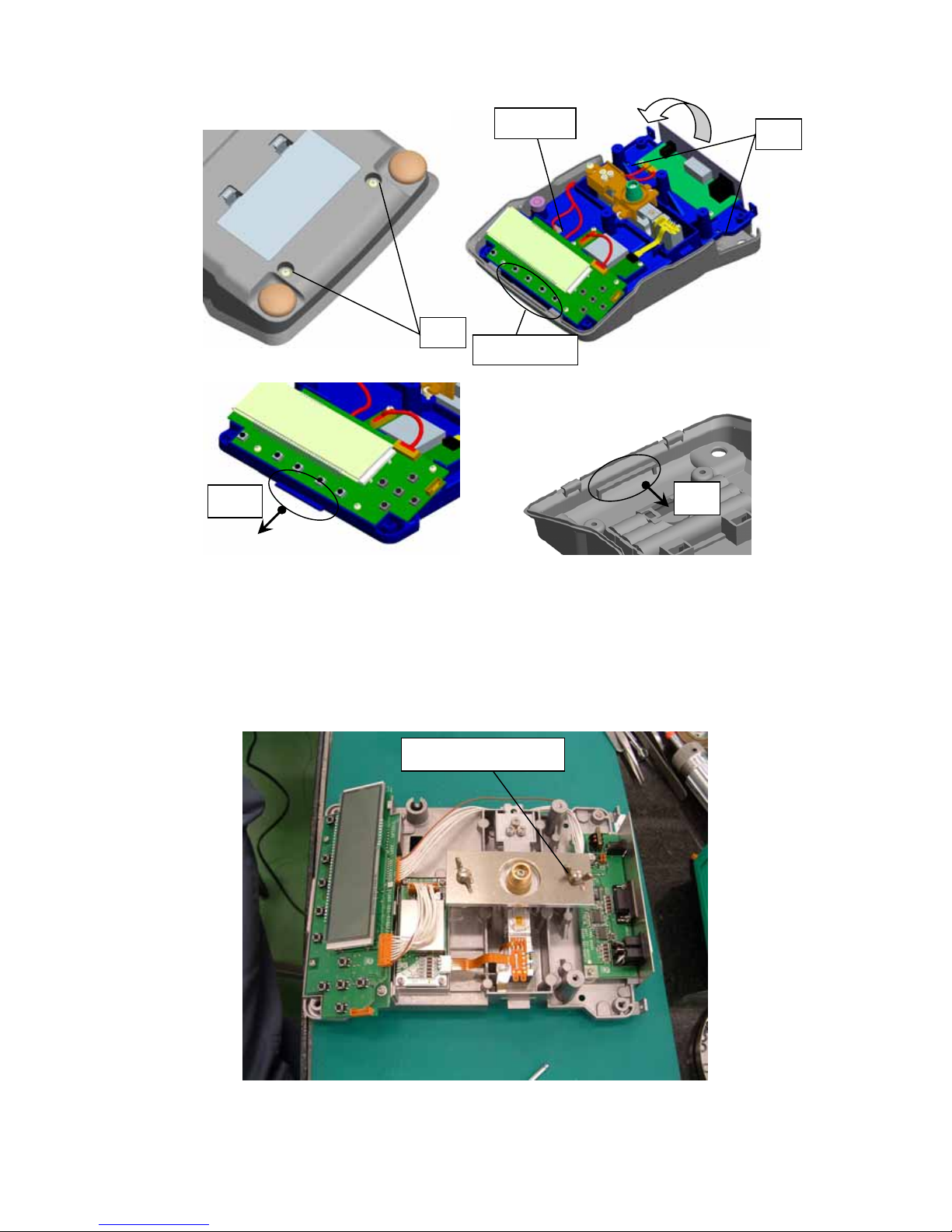
2.2.3.3. Replacing the Power Board Assy (11)
1) Use the procedure in " 2.2.2 Inspecting the Balance Interior (Removing the Case and Pan Support)" to
remove as far as the upper case Assy (6).
2) Disconnect the connector (C5) for cable 10-10 (14), and the connector (C6) for the battery cable (15) that
are connected to the power board Assy (11).
3) Loosen the two M3×6 truss screws (25) fixing the back plate (16) in place.
4) Remove the two M3×8 sems screws (23) fixing the power board Assy (11) in place.
5) Slide the back plate (16) upward, and remove the back plate (16) and power board Assy (11).
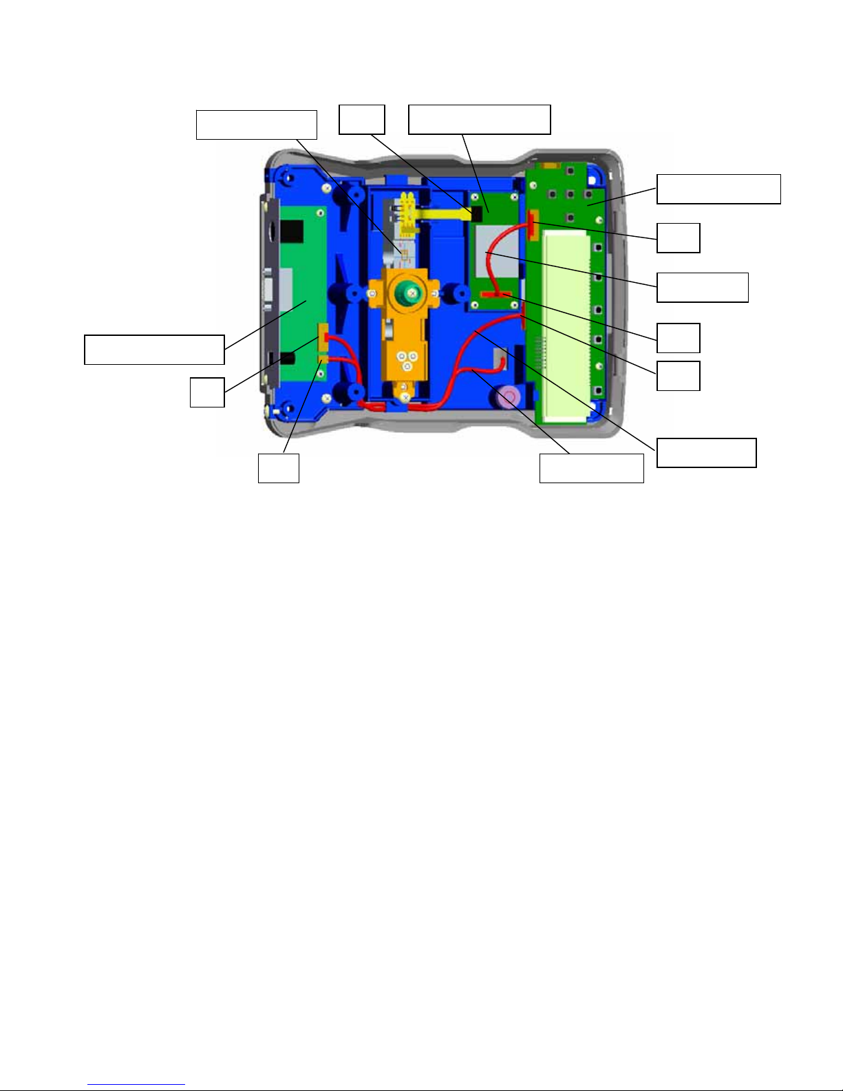
(9) Main board ASSY
(10) Analog board ASSY
(11) Power board ASSY
(12) Load cell ASSY
C1
C2
C3
C4
C5
C6
(13) Cable 9-9
(14) Cable 10-10
(15) Battery cable
- 22 -
6) Remove the two CDHWE101S00 screws (24) fixing the power board Assy (11) and back plate (16) in place.
7) Temporarily tighten the two CDHWE101S00 screws (24) fixing the new power board Assy (11) and back
plate (16) in place.
8) Slide the back plate (16) down, and set the back plate (16) so that it is held down by the M3×6 truss screw
(25).
9) Use two M3×8 sems screws (23) to fix the power board Assy (11) in place.
10) Use two M3×6 truss screws (25) to fix the back plate (16) in place.
11) Tighten the two loosely tightened CDHWE101S00 screws (24).
12) Disconnect the connector for cable ILS 10S-10S-270 (B9) that is connected to the power board Assy (B4).
13) Insert the connector (C5) for cable 10-10 (14) and the connector (C6) for the battery cable (15).
2.2.3.4. Replacing the Load Cell Assy (12)
1) Use the procedure in " 2.2.2 Inspecting the Balance Interior (Removing the Case and Pan Support)" to
remove as far as the upper case Assy (6).
2) Disconnect the connector (C6) for the battery cable (15).
3) Remove the four level adjustment feet (8) on the back of the main body (for the large pan model; the small
pan model has two feet), and the two M4×8 sems screws (22).
* Be careful not to apply force to the load cell Assy.
4) Remove the two M4×8 sems screws (22) fixing the base Assy (17) in place.
5) While removing the connector (C6) from the base Assy (17) hole, lift up the back plate (16) to remove the
base Assy (17).
(16) Back plate
(23)
(24)
(25)
- 23 -
6) Remove the hexagonal socket head bolt on the back of the base Assy (17).
* Be careful not to apply force to the load cell Assy. Also be careful not to drop the load cell Assy.
7) Follow steps 2) to 5) in reverse to attach the new load cell Assy (12).
8) While positioning the load cell Assy with the jig (31), use the hexagonal socket head bolt to attach the load
cell Assy (12).
(22)
(22)
Front hook
s
Cable hole
@C
@C
(31) Cell positioning jig
 Loading...