

Page 1

263-13236E
Magnetically Levitated Turbo Molecular Pump
Model:TMP-3203M (Air cooled type)
Model:TMP-3203MC (Air cooled chemical type)
Model:TMP-3203LM (Wide range type)
Model:TMP-3203LMC (Wide range chemical type)
Model:TMP-3403LMC (Wide range chemical type)
INSTRUCTION MANUAL
Read the instruction manual thoroughly before you use the product.
Keep this instruction manual for future reference.
Semiconductor Equipment Division
Page 2

Introduction
Thank you for choosing the turbo molecular pump made by Shimadzu Corporation.
(hereafter referred to as "turbo molecular pump").
Please read the instruction manual carefully in conjuction with the instruction manual of
"Power Supply Unit" before using turbo molecular pump, and save the instruction manual for
future reference.
Copyrights and Disclaimers
This document is copyrighted by Shimadzu Corporation. Please refrain from reproducing
or copying part or all of this document without permission from Shimadzu.
In an effort to improve the product, this document may be revised in the future without
notice.
Every effort has been made to prepare an accurate and complete manual, but if an error
or omission should be discovered, revisions might not be possible immediately.
Shimadzu does not take responsibility for any effects that may result from the use of this
manual.
Copyright 2003-2006 Shimadzu Corporation.All rights reserved.
©
Magnetically Levitated Turbo Molecular Pump
INSTRUCTION MANUAL
i
Page 3
Precautions for Safe Operation
The instruction manual's nomenclature for warnings and precautions complies with
the following safety warning symbols.
WARNING
CAUTION
NOTICE
Indicates a potentially hazardous situation whitch, if not avoided, could result
in serious injuly or possibly death.
Indicates a potentially hazardous situation whitch, if not avoided, may result in
minor to moderate injuly or equipment damage.
Emphasizes additional information that is provided to ensure the proper use of
this product.
WARNING
Turbo molecular pump repair and/or power supply repair can be very hazardous.
Only trained technicians who are authorized by Shimadzu may do service of
products.
WARNING
Neither overhaul nor modify the pump proper and power supply unit without
admission. Doing so would impair safety of the pump proper.
WARNING
Decisions on system compatibility should be made by the system designer or the person
deciding the specifications after conducting tests as necessary.The responsibility for
guaranteeing the expected performance and safety of the system lies with the person who
decides system compatibility.
ii
263-13236
Page 4

WARNING
・Fix the pump to the device according to 5.1.2.1 and 5.1.2.2. The method to fix the pump is
different depending on the pump model and the size of inlet flange of the pump.
・The device should be fixed to the floor so as not to move. The device should be designed to
endure the torque 1.5 times the rapid shutdown torque to take the safety margin in
preparation for an emergency accident.
・The rotor assembly of the turbo molecular pump rotates at high speed. Large rapid shutdown
torque should be generated when abnormality occurs in the pump by any chance. Incidental
accident will cause the pump to drop out and to make a catastrophe if the pump is fixed by
insufficient method.
WARNING
Do not remove the turbo molecular pump, before safety has been confirmed.
Improper turbo molecular pump use may be hazardous to operator's health in applications not
recommended or approved by Shimadzu. In the event removal of the turbo molecular pump from
an application is required, full protective measures including purging of the turbo molecular pump
with an inert gas and/or apparel are recommended when the turbo molecular pump has been
used in applications that required the use of corrosive, reactive, stimulative, or toxic gases.
Magnetically Levitated Turbo Molecular Pump
INSTRUCTION MANUAL
iii
Page 5

CAUTION
After having operated the turbo molecular pump for evacuation of corrosive gas, keep the
pump internal as vacuumed even after shutdown. Inflow of water content in the air to the pump
internal would cause rapid erosion trouble of the pump internals.
CAUTION
Avoid to install the pump at the following places.
(1) Place where the pump is inevitably exposed to significant vibration and impact.
(2) Unstable place.
(3) Place where the pump is inevitably exposed to magnetic field and radioactive ray.
The pump proper is a precision machine. Be careful not to apply abnormal vibration, shock/
impact to it during transportation.This pump is not connected to grand. Please provide
PE(Protective earth) connection to the chassis of pump in final application.
CAUTION
The following "CAUTIONS" are to prevent operation anomalies.
1.This turbo molecular pump is not approved for use in applications exhausting process gas
containing gallium (Ga, e.g., triethyl gallium, etc.).
2.Protect the pump from any and all types of impact during operation.
3.Do not operate any equipment (i.e. drill motor, welding machine, etc.) that produces electromagnetic pollution, noise, etc., in the immediate proximity of an operating turbo molecular
pumping system (pump, power supply, cables, etc).
4.Do not interrupt the electrical power operating the turbo molecular pump while the turbo
molecular pump is in operation.
5.Do not connect or disconnect the turbo molecular pump control cable during the time the
power supply is "ON".
6.Be sure to use the chemical type pumps to exhaust of gas which contain chlorine, or fluorine.
7.Plasmas may cause the pump rotor to discharge electrically thus damaging the electrical
components.
8.When using the variable speed function to change the pump rotation rate, use a rotation rate
that does not cause resonance with other devices installed at the site.
iv
263-13236
Page 6
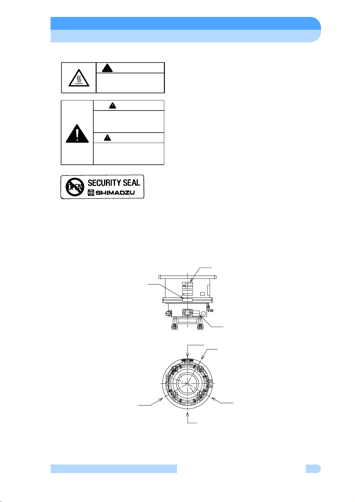
○ Explanation of label
CAUTION
!
HOT SURFACE
Risk of burn. Avoid contact.
やけどのおそれがあります。 触らないで下さい。
高温注意
警 告
ポンプが装置から外れ,人体を傷つける
恐れがあります。取扱説明書に従い確実
にポンプを固定してください。
WARNING
CAN CAUSE INJURY BY DROPED
PUMP, INSTALL PUMP SECURELY
ACCORDING TO INSTRUCTION
MANUAL.
263-16180
(1) HOT SURFACE label
Risk of burn. Keep off from touching surface of the
pump as it is heated.
(2) INSTALL PUMP label
Incidental accident will cause the pump to drop
out and to make a catastrophe if the pump is fixed
by insufficient method.
Fix the pump to the device according to 5.1.2
「Installation of the Pump」.
(3) SECURITY seal
This label certificates that the product was made
or maintenanced by Shimadzu or by Shimadzu
authorized facility .
In case "this label is removed" or "there is a mark
showing once this label has been removed",
Shimadzu warranty shall not be applied to the
product.
○ Location of label
(1)
(3)
(2), (3)
(2)
(2)
(1)
(1)
(1)
Series of TMP-3203 and TMP-3403LMC
Label attachment phase
Magnetically Levitated Turbo Molecular Pump
INSTRUCTION MANUAL
v
Page 7
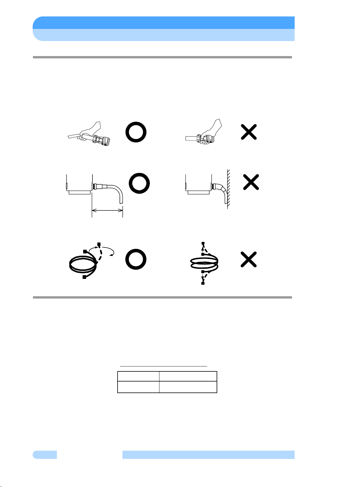
○ Installation Precautions
Do not apply abnormal loads to the turbo molecular pump control cable plug and/or connector.
Abnormal loads may cause cable disconnection.
(1) Do not pull the turbo molecular pump control cable by the connector or plug.
(2) Do not allow any electrical cables to be in tension or to have very tight bending radii.
240mm
(3) Do not twist the turbo molecular pump control cable during connection.
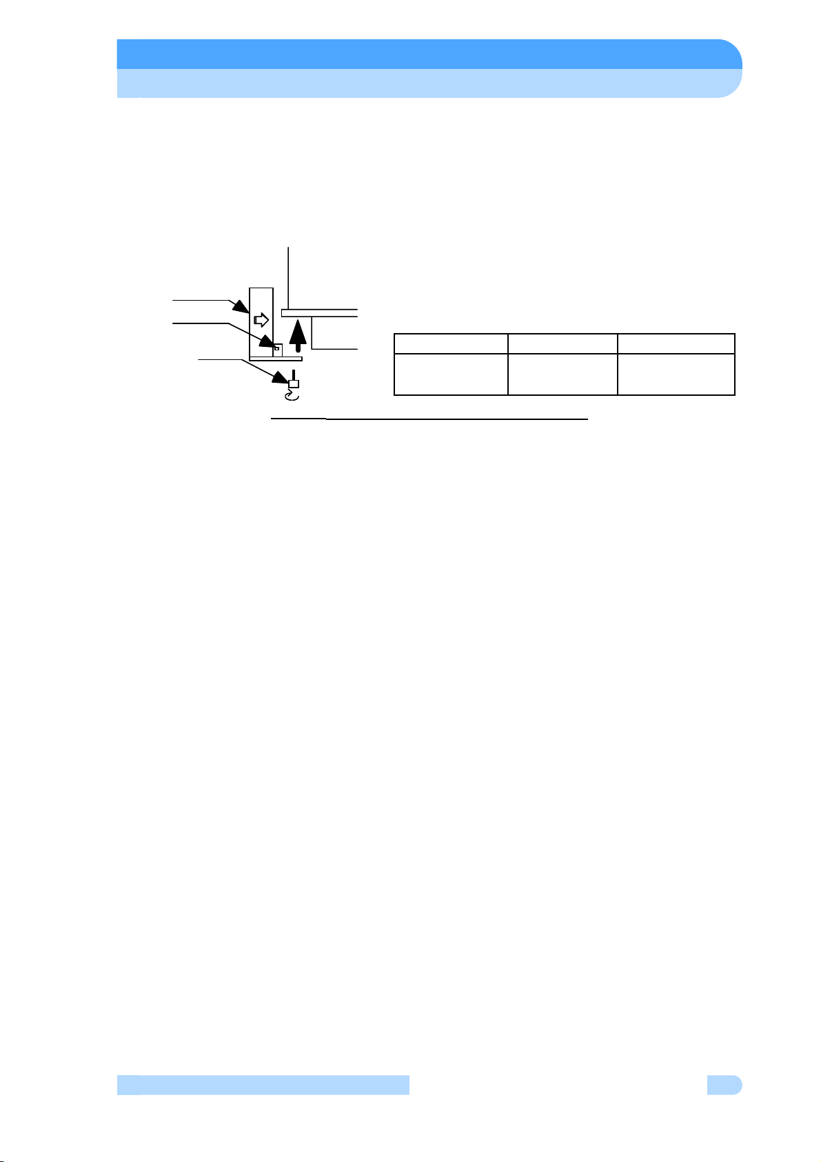
○ Part Replacement
The lifetime of parts are specified as below.
The request for changing parts exceeding the estimated lifetime should be made to Shimadzu
or an approved service company in order for safety and adequate performance of the pump and
power supply unit.
Tabl e 1 Estimated Part Life.
vi
263-13236
Parts List
Cooling fan 5 years
Estimated Part Life
Page 8
○ Air Cooled Turbo Molecular Pump
For the air cooled turbo molecular pumps, it is necessary to clean the cooling fan periodically
because of the cooling fan collecting dust, debris, etc. Shimadzu recommends removal of the
cooling fan for all methods of cleaning (compressed air, etc.) to prevent the particles, cleaning
debris, from accumulating in or on the turbo molecular pump. Please refer to Fig. 1 how to
change fan.
COOLING UNIT
FLOW
CONNECTOR
SCREW
PUMP
Pump model Parts name Parts Number
TMP-3203M
TMP-3203MC
Cooling unit
DV24V
262-76043-01
Fig. 1 How to Change the Cooling Fan Unit
○ Warranty period
12 months on new TMP's from the date of shipment from Shimadzu, or from any of its
worldwide sales offices.
○ Conditional warranty
During the warranty period and under normal operation, if the TMP fails to meet its product
specification due to defects in material and/or workmanship, Shimadzu will, at its discretion,
either repair it or exchange it with a new one for free.
○ Scope of the warranty
The warranty covers only TMPs, controllers and accessories sold by Shimadzu.
○ Warranty of repaired or replacement parts
In-warranty repaired or replacement parts are warranted only for the remaining unexpired
portion of the original warranty period applicable to the parts that have been repaired or replaced.
○ Exemption from the warranty
During the warranty period, Shimadzu will charge for repair or exchange in the following cases:
1) Failure caused by natural disasters or fire.
2) Failure or functional deterioration due to the following:
a) Pumping of special gases and materials
b) Ingestion of foreign objects through the TMP's protective net
c) TMP is operated differently than what is prescribed in the instruction manual
Magnetically Levitated Turbo Molecular Pump
INSTRUCTION MANUAL
vii
Page 9

d) When Shimadzu determines through failure analysis that the cause of failure was due to
abnormal operation or external circumstances. our engineers judge that the cause of the
trouble is an irregular operation
3) Warranty is voided if the "Security Seal" on the product has been removed, hampered with,
or altered.
○ Disposal of Products and Parts
Please contact Shimadzu for proper disposal of its products or parts. There is a possibility to
pollute the environment with the material of the parts, when you dispose this product in an inappropriate way.
○ LIMITATION OF LIABILITY
EXCEPT AS STATED HEREIN, SHIMADZU MAKES NO WARRANTY, EXPRESSED OR
IMPLIED (EITHER IN FACT OR BY OPERATION OF LAW), STATUTORY OR OTHERWISE:
AND, EXCEPT AS STATED HEREIN, SHIMADZU SHALL HAVE NO LIABILITY FOR
SPECIAL OR CONSEQUENTIAL DAMAGES OF ANY KIND OR FROM ANY CAUSE ARISING
OUT OF THE SALE, INSTALLATION, OR USE OF ANY OF ITS PRODUCTS.
viii
263-13236
Page 10

TABLE OF CONTENTS
Introduction
Copyrights and Disclaimers . . . . . . . . . . . . . . . . . . . . . . . . . . . . . . . . i
Precautions for Safe Operation . . . . . . . . . . . . . . . . . . . . . . . . . . . . ii
○ Explanation of label . . . . . . . . . . . . . . . . . . . . . . . . . . . . . . . . . . . v
○ Location of label. . . . . . . . . . . . . . . . . . . . . . . . . . . . . . . . . . . . . . v
○ Installation Precautions . . . . . . . . . . . . . . . . . . . . . . . . . . . . . . . . vi
○ Part Replacement . . . . . . . . . . . . . . . . . . . . . . . . . . . . . . . . . . . . vi
○ Air Cooled Turbo Molecular Pump. . . . . . . . . . . . . . . . . . . . . . . . vii
○ Warranty period . . . . . . . . . . . . . . . . . . . . . . . . . . . . . . . . . . . . . . vii
Table of contents
○ Conditional warranty . . . . . . . . . . . . . . . . . . . . . . . . . . . . . . . . . . vii
○ Scope of the warranty . . . . . . . . . . . . . . . . . . . . . . . . . . . . . . . . . vii
○ Warranty of repaired or replacement parts . . . . . . . . . . . . . . . . . vii
○ Exemption from the warranty . . . . . . . . . . . . . . . . . . . . . . . . . . . . vii
○ Disposal of Products and Parts . . . . . . . . . . . . . . . . . . . . . . . . . viii
○ LIMITATION OF LIABILITY . . . . . . . . . . . . . . . . . . . . . . . . . . . . viii
TABLE OF CONTENTS . . . . . . . . . . . . . . . . . . . . . . . . . . . . . . . . . . ix
Section 1 OUTLINE AND DESCRIPTIONS
1.1 Outline . . . . . . . . . . . . . . . . . . . . . . . . . . . . . . . . . . . . . . . . . . . 2
1.2 Descriptions . . . . . . . . . . . . . . . . . . . . . . . . . . . . . . . . . . . . . . . 3
1.2.1 Outside drawing of Pump Main Unit . . . . . . . . . . . . . . . . . . . . . . . . 3
1.2.1.1 Outside drawing of series of TMP-3203 . . . . . . . . . . . . . . . 3
1.2.1.2 Outside drawing of TMP-3403LMC . . . . . . . . . . . . . . . . . . 5
1.2.2 Standard Accessories . . . . . . . . . . . . . . . . . . . . . . . . . . . . . . . . . . . 6
Section 2 IDENTIFICATION AND FUNCTION
2.1 Pump Main Unit . . . . . . . . . . . . . . . . . . . . . . . . . . . . . . . . . . . . 8
Magnetically Levitated Turbo Molecular Pump
INSTRUCTION MANUAL
ix
Page 11

Table of contents
Section 3 CONSTRUCTION AND PRINCIPLE
3.1 Pump Construction. . . . . . . . . . . . . . . . . . . . . . . . . . . . . . . . . 10
3.2 Principle of Turbo Molecular Pumping . . . . . . . . . . . . . . . . . . 10
Section 4 SPECIFICATIONS
4.1 Pump Main Unit . . . . . . . . . . . . . . . . . . . . . . . . . . . . . . . . . . . 14
4.1.1 Specification of series of TMP-3203 . . . . . . . . . . . . . . . . . . . . . . . 14
4.1.2 Specification of TMP-3403LMC . . . . . . . . . . . . . . . . . . . . . . . . . . . 15
4.2 Standards Fulfilled . . . . . . . . . . . . . . . . . . . . . . . . . . . . . . . . . 16
Section 5 INSTALLATION
5.1 Installation . . . . . . . . . . . . . . . . . . . . . . . . . . . . . . . . . . . . . . . 18
5.1.1 Pump Mounting Direction. . . . . . . . . . . . . . . . . . . . . . . . . . . . . . . . 18
5.1.2 Installation of the Pump . . . . . . . . . . . . . . . . . . . . . . . . . . . . . . . . . 19
5.1.2.1 Installation of series of TMP-3203 . . . . . . . . . . . . . . . . . . 21
5.1.2.2 Installation of TMP-3403LMC . . . . . . . . . . . . . . . . . . . . . . 23
5.1.3 Example of piping connection . . . . . . . . . . . . . . . . . . . . . . . . . . . . 24
5.1.4 Center of gravity of the pump. . . . . . . . . . . . . . . . . . . . . . . . . . . . . 25
5.2 Connection of the Pump to the Power Supply Unit . . . . . . . . 26
5.3 Interlock for Vacuum System . . . . . . . . . . . . . . . . . . . . . . . . . 27
Section 6 OPERATION
6.1 Outline . . . . . . . . . . . . . . . . . . . . . . . . . . . . . . . . . . . . . . . . . . 30
6.1.1 Introduction . . . . . . . . . . . . . . . . . . . . . . . . . . . . . . . . . . . . . . . . . . 30
6.2 Start-up Preparation . . . . . . . . . . . . . . . . . . . . . . . . . . . . . . . . 31
6.2.1 Start-up Preparation . . . . . . . . . . . . . . . . . . . . . . . . . . . . . . . . . . . . 31
6.3 Start-up. . . . . . . . . . . . . . . . . . . . . . . . . . . . . . . . . . . . . . . . . . 31
6.3.1 Start-up Sequence . . . . . . . . . . . . . . . . . . . . . . . . . . . . . . . . . . . . . 31
6.4 Shutting Down . . . . . . . . . . . . . . . . . . . . . . . . . . . . . . . . . . . . 32
6.5 Baking Operation . . . . . . . . . . . . . . . . . . . . . . . . . . . . . . . . . . 34
x
263-13236
Page 12

Table of contents
Section 7 GAS PURGE
Section 8 TURBO MOLECULAR PUMP RECONDITION
8.1 Turbo Molecular Pump Return Request . . . . . . . . . . . . . . . . 40
8.2 Turbo Molecular Pump Decontamination. . . . . . . . . . . . . . . . 41
8.3 Touch-Down Bearing Replacement . . . . . . . . . . . . . . . . . . . . 41
8.4 Check of the rotor blades. . . . . . . . . . . . . . . . . . . . . . . . . . . . 41
Section 9 TROUBLESHOOTING
9.1 Vacuum Pressure Rise . . . . . . . . . . . . . . . . . . . . . . . . . . . . . 44
9.2 Abnormal Noise and/or Vibration . . . . . . . . . . . . . . . . . . . . . . 44
Magnetically Levitated Turbo Molecular Pump
INSTRUCTION MANUAL
xi
Page 13

Table of contents
This page is intentionally left blank.
xii
263-13236
Page 14

1OUTLINE AND
DESCRIPTIONS
1
1.1 Outline
1.2 Descriptions
1.2.1 Outside drawing of Pump Main Unit
1.2.1.1 Outside drawing of series of TMP-3203
1.2.1.2 Outside drawing of TMP-3403LMC
1.2.2 Standard Accessories
Page 15

SECTION 1 OUTLINE AND DESCRIPTIONS
1
1.1 Outline
The turbo molecular pump is a vacuum pump. The turbo molecular pump is used with a
backing vacuum pump to create a high vacuum in a vacuum chamber.
Typical Applications ; Semiconductor equipments,
Industrial equipments,
R&D applications,
The other ultra high vacuum applications.
The turbo molecular pump (one standard set) consists of the following items.
・Pump 1
・Power Supply Unit 1
・Control Cable 1
・Motor Cable 1
・Standard Accessories 1 Set
This instruction manual explains the operation of the pump unit. For more detailed instructions
regarding the power supply unit, please refer to the Power Supply Unit Instruction Manual.
2
263-13236
Page 16
1.2 Descriptions
1.2 Descriptions
1.2.1 Outside drawing of Pump Main Unit
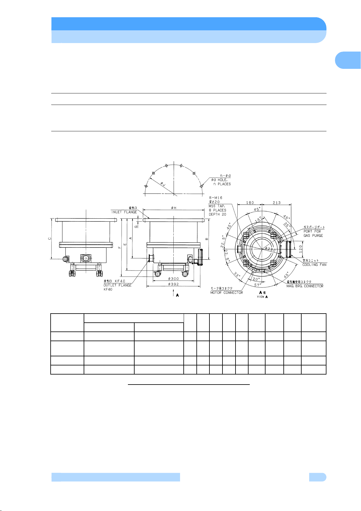
1.2.1.1 Outside drawing of series of TMP-3203
1
INLET
FLANGE
VG350 P/N 262-78430-62 P/N 262-78430-72 287 294 289 375 420 22
ISO320B
Special
VG300 P/N 262-78430-67 P/N 262-78430-77 307 314 309 395 440 18.5
VG250 P/N 262-78430-68 P/N 262-78430-78 331 338 333 419 464 18.5
TMP-3203M TMP-3203MC
P/N 262-78430-63 P/N 262-78430-73 287 294 289 375 420 22.5
Parts number
Fig.1-1
ABCEF G φH φJn-φd
TMP-3203M and TMP-3203MC
Magnetically Levitated Turbo Molecular Pump
INSTRUCTION MANUAL
φ450 φ420 12-φ15
φ425 φ395 12-φ13
φ400 φ370 12-φ13
φ350 φ320 12-φ13
3
Page 17
SECTION 1 OUTLINE AND DESCRIPTIONS
1
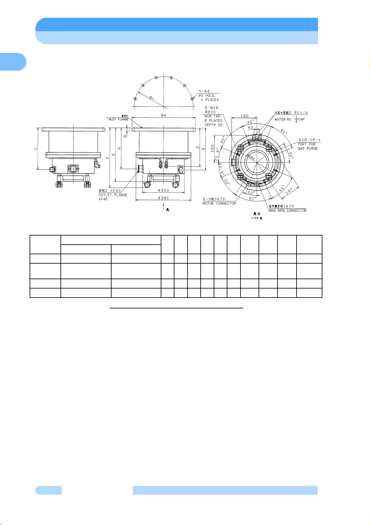
INLET
FLANGE
VG350 P/N 262-78430-42 P/N 262-78430-52 287 294 289 270 375 420 22
ISO320B
Special
VG300 P/N 262-78430-47 P/N 262-78430-57 307 314 309 290 375 440 18.5
VG250 P/N 262-78430-48 P/N 262-78430-58 331 338 333 314 419 464 18.5
TMP-3203LM TMP-3203LMC
P/N 262-78430-43 P/N 262-78430-53 287 294 289 270 375 420 22.5
Parts number
ABCDEF G
Fig.1-2 TMP-3203LM and TMP-3203LMC
φH φJ
φ450 φ420 12-φ15
φ425 φ395 12-φ13
φ400 φ370 12-φ13
φ350 φ320 12-φ13
n-φd
4
263-13236
Page 18
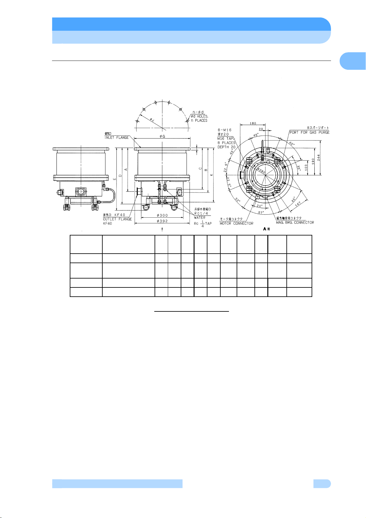
1.2.1.2 Outside drawing of TMP-3403LMC
1.2 Descriptions
1
F
INLET
FLANGE
VG350 P/N 262-78503-52 287 294 270 375 420 22
ISO320B
Special
VG300 P/N 262-78503-57 307 314 290 395 440 18.5
VG250 P/N 262-78503-58 331 338 314 419 464 18.5
Parts number ABCDE F
P/N 262-78503-53 287 294 270 375 420 22.5
Fig.1-3
TMP-3403LMC
φG
φ450
φ425
φ400
φ350
K
φHn-φd
360
φ420 12-φ15
360
φ395 12-φ13
380
φ370 12-φ13
404
φ320 12-φ13
Magnetically Levitated Turbo Molecular Pump
INSTRUCTION MANUAL
5
Page 19

SECTION 1 OUTLINE AND DESCRIPTIONS
1.2.2 Standard Accessories
1
Series of TMP-3203
Description Q'ty Notes Parts number
O-ring gasket for VG350
Gasket for inlet flange
1
(Note)
Bolt set for inlet flange
2
(Note)
3 Centering with O-ring 1
4Clamp 1
5 Instruction manual 1 English
1
1
O-ring gasket for VG300
O-ring gasket for ISO320B Special
O-ring gasket for VG250
VG350:Hex Head, M12 × 40, 12PC
(A2-70)
VG300:Hex Head, M12 × 35, 12PC
(12.9)
ISO320B Special: Hex Head,
M12 × 40, 12PC (12.9)
VG250:Stud Bolt, M12 × 47, 12PC
(12.9)
KF40
KF40
036-13516
036-13515
036-15554-55
036-13514
─
035-06004-14
035-06004-03
263-13236
TMP-3403LMC
Description Q'ty Notes Parts number
O-ring gasket for VG350
Gasket for inlet flange
1
(Note)
Bolt set for inlet flange
2
(Note)
3 Centering with O-ring 1
4Clamp 1
5 Instruction manual 1 English
(Note) One of followings.
1
1
O-ring gasket for VG300
O-ring gasket for ISO320B Special
O-ring gasket for VG250
VG350:Hex Head, M12 × 40, 12PC
(12.9)
VG300:Hex Head, M12 × 35, 12PC
(12.9)
ISO320B Special: Hex Head,
M12 × 40, 12PC (12.9)
VG250:Stud Bolt, M12 × 47, 12PC
(12.9)
KF40
KF40
036-13516
036-13515
036-15554-55
036-13514
─
035-06004-14
035-06004-03
263-13236
6
263-13236
Page 20

2IDENTIFICATION AND
FUNCTION
2
2.1 Pump Main Unit
Page 21

SECTION 2 IDENTIFICATION AND FUNCTION
2.1 Pump Main Unit
2
1
5
4
3
TMP-3203LM/LMC TMP-3403LMC
1
5
1
5
4
3
26
6
2
8
4
3 2 7
TMP-3203M/MC
Fig.2-1 Pump Main Unit
(1) INLET FLANGE . . . . . . . . . . . . . Inlet flange, joint the turbo molecular pump, VG350,
ISO320B Special, VG30, VG250 are also available.
(2) PORT FOR GAS PURGE . . . . . Gas purge adaptor port
(see Section 7 "GAS PURGE")
(3) OUTLET FLANGE. . . . . . . . . . . Outlet flange, connect a backing vacuum pump or its
related pipe connection, KF40.
(4) MOTOR CONNECTOR. . . . . . . Motor cable receptacle
(5) CONTROL CONNECTOR. . . . . Control cable receptacle
(6) COOLING WATER PIPELINE. . Cooling water pipe connector, Rc1/4
(7) COOLING FAN . . . . . . . . . . . . . Cooling Fan
263-13236
Page 22

3CONSTRUCTION AND
PRINCIPLE
3
3.1 Pump Construction
3.2 Principle of Turbo Molecular Pumping
Page 23

SECTION 3 CONSTRUCTION AND PRINCIPLE
3.1 Pump Construction
Fig. 3-1 is a sectional drawing of the TMP-3203LM and TMP-3203LMC and TMP-3403LMC
3
magnetic bearing type turbo molecular pump. The built-in high frequency motor (1) is accelerated
to the specified revolutions (speed) by the high frequency power supply unit. Rotor blades (4) are
fitted onto the drive shaft (3) and the stator blades (5) are arranged in between the rotor blades.
A positioning spacer (6) is inserted between the stator blades. The configurations and profiles of
the stator blades and rotor blades are designed for high efficiencies in various applications. The
upper stages of the rotor blade and stator blade configurations are ideally designed for high gas
throughput. The compression ratio of the stator blades and rotor blades becomes higher as the
gas molecules converge into the lower stage configurations. The profiles of the stator blades and
rotor blades are matched for the desired function.
A radial magnetic bearing (7) is used at the top and bottom of the drive shaft. The axial
magnetic bearings (8) are used to levitate a disk attached to the drive shaft between the axial
magnetic bearings. Each magnetic bearing is provided with a gap sensor (10) to detect the rotor
position. Fig. 3-2 illustrates the outline of 5 - axes control. The rotor is levitated by the control of
these 5 axes allowing rotational freedom.
A touchdown bearing is used at the top and bottom of the casing for safety protection of the
rotor and pump should the magnetic bearings become damaged. The touchdown bearings are
dry and oil free.
The cooling water pipe (14) is provided to cool the pump. With the air-cooled turbo molecular
pumps TMP-3203M and TMP-3203MC, cooling fans are provided instead of the cooling water
pipe (14).
Fig. 1-1 through Fig. 1-3 show the outside dimensions of the turbo molecular pump.
3.2 Principle of Turbo Molecular Pumping
The principle of turbo molecular pumping assumes gas molecules collide with a surface plane
(the blade of the pump rotor) moving in a radial span of very high speed in a space with an
enlarged mean free gas path (generally a vacuum area of less pressure than 0.1 Pa). Assuming
no heat is exchanged between the gas molecule and the pump rotor blade, the speed of the
pump rotor blade is added to the speed of the gas molecule, converting the gas molecule's nonoriented thermal motion to a motion with direction. Thus the gas molecule has received an
impulse in a desired flow direction.
10
263-13236
Page 24

④
3.2 Principle of Turbo Molecular Pumping
⑬
3
⑪
⑩
③
①
⑭
⑫
⑩
⑤
⑥
⑨
⑦
②
⑨
⑧
Fig.3-1 Pump Sectional Drawing
(1) High frequency motor (6) Spacer (11) Inlet flange
(2) Receptacle (7) Radial magnetic bearing (12) Outlet flange
(3) Drive shaft (8) Axial magnetic bearing (13) Protective net
(4) Rotor blade (9) Touch-down bearing (14) Cooling water pipeline
(5) Stator blade (10) Gap sensor (pipe connection port)
Magnetically Levitated Turbo Molecular Pump
INSTRUCTION MANUAL
11
Page 25

SECTION 3 CONSTRUCTION AND PRINCIPLE
The movement of an object has 6 degrees of freedom. Levitation can be achieved in a turbo
molecular pump by controlling the following 5 degrees of freedom (excluding the rotational
degree (Z axis) of freedom).
Z
3
rotational axis
Parallel movement
Rotation
X
Y
ZZ Z
X Y Y
Radial displacement Axial displacement
Z
X
Z
Y
Movement of rotor and restricted five degrees of freedom
12
263-13236
Z
X
1
X
2
Y
1
Y
2
Fig.3-2 Outline of 5-Axes Control
5-axes control
① X
1
② Y
1
③ X
2
④ Y
2
⑤ Z
Page 26

4SPECIFICATIONS
4
4.1 Pump Main Unit
4.1.1 Specification of series of TMP-3203
4.1.2 Specification of TMP-3403LMC
4.2 Standards Fulfilled
Page 27

SECTION 4 SPECIFICATIONS
4.1 Pump Main Unit
4.1.1 Specification of series of TMP-3203
Turbo molecular pump model TMP-3203M TMP-3203MC TMP-3203LM TMP-3203LMC
Cooling method Cooling fan Water
4
Ultimate pressure (Note 1) 10
Maximum Argon gas through put
(Note 2)
Maximum allowable inlet pressure
(Nitrogen gas)
Maximum allowable outlet
pressure
Pumping speed N
(Note 3) He
Compression ratio N
Rated speed 21000 rpm
Start-up time 13 minutes
Mounting position
Bake-out temperature at an inlet
flange
Vibration level (by Shimadzu's
method)
Inlet flange
Outlet flange KF40
Mass 70 kg
Admissible throughput of purge
gas
Admissible pumping speed of
backing vacuum pump in case of
gas purge
Environmental Temperatures
H
He
H
2
2
2
2
-9
Pa order 10-8 Pa order 10-9 Pa order 10-8 Pa order
250 mL/min 400 mL/min 1200 mL/min 2200 mL/min
0.4 Pa 40 Pa
40 Pa 270 Pa
3200 L/s
3000 L/s
2400 L/s
1 × 10⁹ or more
3 × 10
1 × 10
In any desired direction(Note 4)
120 ℃ or less
0.01 μm or less (0-peak)
VG350(Note 5)
20 to 30 mL/min(Note 2)
1500 L/min or more
Operation : 0 to 40 ℃ / Storage : -25 to 70 ℃
5
4
14
Admissible ambient magnetic field
Water Flow rate
Radial direction
Axial direction
Pressure
Temperature
N/A
3 mT
15 mT
2 to 4 L/min
0.2 to 0.5 MPa
5 to 25 ℃
(Note 1) When using a metal gasket at the inlet flange. When using an o-ring gasket , the
-7
ultimate pressure is 10
Pa order.
(Note 2) mL/min : volume flow rate at 0 ℃ , 1 atm. (Compatible with SCCM.)
(Note 3) Without a protective net. Pumping speed for N
is 2950 L/s with a protective net.
2
(Note 4) The outlet flange of the turbo molecular pump should face horizontally or vertically
when installing the pump horizontally and obliquely.
(Refer to 5.1.1「Pump Mounting Direction」)
(Note 5) VG300, VG250 and ISO320B Special are also available.
263-13236
Page 28

4.1.2 Specification of TMP-3403LMC
Turbo molecular pump model TMP-3403LMC
Cooling method Water
Ultimate pressure 10
Maximum Argon through put
(Note 1)
Maximum allowable inlet pressure
(Nitrogen gas)
Maximum allowable outlet
pressure
Pumping speed N
2
(Note 2) He
H
2
Compression ratio N
He
H
2
2
Rated speed 22020 rpm
Start-up time 15 minutes
Mounting position
In any desired direction(Note 3)
Bake-out temperature at an inlet
flange
Vibration level (by Shimadzu's
method)
0.01 μm or less (0-peak)
Inlet flange
Outlet flange KF40
Mass 70 kg
Admissible throughput of purge
gas
20 to 30 mL/min(Note 1)
Admissible pumping speed of
backing vacuum pump in case of
gas purge
Environmental Temperatures
Operation : 0 to 40 ℃ / Storage : -25 to 70 ℃
-7
Pa order
2200 mL/min
10 Pa
270 Pa
3300 L/s
3100 L/s
2400 L/s
1 × 10
1 × 10
6 × 10
120 ℃ or less
VG350(Note 4)
1500 L/min or more
4.1 Pump Main Unit
4
9
5
4
Admissible ambient magnetic field
Radial direction
Axial direction
Water Flow rate
Pressure
Temperature
3 mT
15 mT
2 to 4 L/min
0.2 to 0.5 MPa
5 to 25 ℃
(Note 1) mL/min : volume flow rate at 0 ℃ , 1 atm. (Compatible with SCCM.)
(Note 2) Without a protective net. Pumping speed for N
is 3000 L/s with a protective net.
2
(Note 3) The outlet flange of the turbo molecular pump should face horizontally or vertically
when installing the pump horizontally and obliquely.
(Refer to 5.1.1「Pump Mounting Direction」)
(Note 4) VG300, VG250 and ISO320B Special are also available.
Magnetically Levitated Turbo Molecular Pump
INSTRUCTION MANUAL
15
Page 29

SECTION 4 SPECIFICATIONS
4.2 Standards Fulfilled
EN61010-1; 2001
4
Safety
EMC
UL61010A-1
SEMI S2
EN1012-2; 1996
EN61326-1; 1997 + A1; 1998 + A2; 2001 class A
EN61000-3-2; 1995 + A14; 2000
SEMI F47
16
263-13236
Page 30

5INSTALLATION
5
5.1 Installation
5.1.1 Pump Mounting Direction
5.1.2 Installation of the Pump
5.1.2.1 Installation of series of TMP-3203
5.1.2.2 Installation of TMP-3403LMC
5.1.3 Example of piping connection
5.1.4 Center of gravity of the pump
5.2 Connection of the Pump to the Power Supply Unit
5.3 Interlock for Vacuum System
Page 31

SECTION 5 INSTALLATION
5.1 Installation
5.1.1 Pump Mounting Direction
This turbo molecular pump can be installed in vertical, the horizontal, inverted, oblique position.
5
The outlet flange of the pump should face horizontally or vertically when installing the pump
horizontally and obliquely.
When an installation direction is non-appropriate, reliability of operation may deteriorate.
(Refer to Fig. 5-1)
Inverted position
Vacuum
chamber
Horizontal position
Outlet
Oblique position
gravity
direction
Horizontal
position
Oblique position
Vertical position
Outlet
upward
18
Vertical position
downward
Fig. 5-1 Mounting Direction of Magnetic Levitated Turbo Molecular Pump
263-13236
gravity
direction
Page 32

5.1 Installation
5.1.2 Installation of the Pump
WARNING
・Fix the pump to the device according to 5.1.2.1 and 5.1.2.2. The method to fix the pump is
different depending on the pump model and the size of inlet flange of the pump.
・The device should be fixed to the floor so as not to move. The device should be designed to
endure the torque 1.5 times the rapid shutdown torque to take the safety margin in
preparation for an emergency accident.
・The rotor assembly of the turbo molecular pump rotates at high speed. Large rapid shutdown
torque should be generated when abnormality occurs in the pump by any chance. Incidental
accident will cause the pump to drop out and to make a catastrophe if the pump is fixed by
insufficient method.
5
CAUTION
Avoid to install the pump at the following places.
(1) Place where the pump is inevitably exposed to significant vibration and impact.
(2) Unstable place.
(3) Place where the pump is inevitably exposed to magnetic field and radioactive ray.The
pump proper is a precision machine. Be careful not to apply abnormal vibration, shock/
impact to it during transportation.
This pump is not connected to grand. Please provide PE(Protective earth) connection to the
chassis of pump in final application.
NOTICE
Before touching the pump internals and the vacuum chamber, put a pair of nylon gloves without
fail. Avoid direct touch with them. Internal contamination of the vacuum chamber or the pump
would cause failure of adequate vacuuming performance.
When using a hydraulic rotary pump with vibration of wide amplitude, as a backing vacuum
pump, undertake proper anti-vibration measure. (As a guideline, control the vibration to 0.1 G /
50 Hz max at the outlet connection port of the turbo molecular pump.)
This pump is a precision pump. To protect the pump from torsion due to external piping load,
use a bellows joint or a flexible tube to either the pump inlet or outlet, without fail.
Magnetically Levitated Turbo Molecular Pump
INSTRUCTION MANUAL
19
Page 33

SECTION 5 INSTALLATION
CAUTION
The center of gravity of the pump is indicated in Fig. 5-8. Be sure that the pump does not move
or fall down during installation or storage.
5
CAUTION
The casters provided with the pump are only auxiliary equipment for installation and storage.
Use a trolley etc. for long-distance transportation.
Fix the pump in the manner shown in Fig. 5-2
Vacuum
chamber
PUMP
Fig. 5-2 Lifting Method
Vacuum
chamber
PUMP
20
263-13236
Page 34

5.1 Installation
5.1.2.1 Installation of series of TMP-3203
Please fix the inlet flange of turbo molecular pump to the flange of vacuum chamber , and the
base bottom of the pump to the frame of the device by the bolts of regulated grade, size, number,
and tightening torque for each flange. (Refer to Table 5-1 and Table 5-2)
When you fix the pump, use all of the bolt holes of the inlet flange of the pump.
When you connect piping and the valve, etc. between the vacuum chamber and the turbo
molecular pump
,please fix all the bolt holes to those connection points by the method of fixing
the recommendation shown in Table 5-1and Table 5-2.
VACUUM
CHAMBER
OUTSIDE
DEVICE
DEVICE
FRAME
BASE
BOTTOM
RAPID SHUTDO WN
TORQUE
INLET
FLANGE
Rods whitch have the
sufficient torque
strength.
Fixed both by the inlet flange and the base of TMP
Description Rapid Shutdown Torque
TMP-3203M/MC/LM/LMC
Fig. 5-3 Installation of series of TMP-3203
Table 5-1 The recommended fixing bolt
Fixing method Both by the inlet flange and the base (recommended method)
Inlet flange VG350 VG300
Bolt Size,
Quantity
Inlet flange
Base
Material stainless steel
Grade
Washer
Plain washer and
spring lock washer
VACUUM
CHAMBER
INLET
FLANGE
RAPID SHUTDOWN TORQUE
OUTSIDE
DEVICE
Fixed only by the inlet flange of TMP
59,100 N
・
m
ISO320B
Special
VG250
M12,12PC
M16,8 PC
A2-70(JIS B 1054)
Special washer (Note) and spring lock washer
5
Fixing method Only by the inlet flange
Inlet flange VG350 VG300
Bolt Size,Quantity
M12,12PC
ISO320B
Special
Material stainless steel SCM435 (JIS G 4105) or equivalent
Grade
Washer
A2-70(JIS B 1054)
Plain washer and
spring lock washer
Special washer (Note) and spring lock washer
12.9 (JIS B 1051)
(Note ) The special washers are attached to the inlet flange of TMP when shipping.
Do not remove them at the time of TMP installation.
Refer to Fig. 5-4 for the details of the bolt attaching part.
Magnetically Levitated Turbo Molecular Pump
INSTRUCTION MANUAL
VG250
21
Page 35

SECTION 5 INSTALLATION
Bolt hole
Inlet flange
Spring lock washer
5
Special washer
Fixing bolt
Vacuum chamber
Inlet flange
Special washer
When shipping After installation
Fig. 5-4 Example of the fixing method using the special washer
Table 5 - 2 Tightening torque of the fixing bolt
Size of bolt Tightening torque [N•m]
M12
M16
16
41
~ 26
~ 66
22
263-13236
Page 36

5.1 Installation
5.1.2.2 Installation of TMP-3403LMC
Please fix the inlet flange of turbo molecular pump to the flange of vacuum chamber , and
the base bottom of the pump to the frame of the device by the bolts of regulated grade, size,
number, and tightening torque for each flange. (Refer to Table 5-2 and Table 5-3)
When you fix the pump, use all of the bolt holes of the inlet flange of the pump.
When you connect piping and the valve, etc. between the vacuum chamber and the turbo
molecular pump
,please fix all the bolt holes to those connection points by the method of fixing
the recommendation shown in Table 5-2 and Table 5-3.
VACUUM
CHAMBER
OUTSIDE
DEVICE
DEVICE
FRAME
BASE
BOTTOM
RAPID SHUTDO WN
TORQUE
INLET
FLANGE
Rods whitch have the
sufficient torque
strength.
Fixed both by the inlet flange and the base of TMP
Description Rapid Shutdown Torque
TMP-3403LMC
Fig. 5-5 Installation of TMP-3403LMC
Table 5-3 The recommended fixing bolt
Fixing method Both by the inlet flange and the base (recommended method)
Inlet flange VG350 VG300
Bolt Size,
Quantity
Inlet flange
Base
Material stainless steel
Grade
Washer
Plain washer and
spring lock washer
VACUUM
CHAMBER
INLET
FLANGE
RAPID SHUTDOWN TORQUE
OUTSIDE
DEVICE
Fixed only by the inlet flange of TMP
60,800 N
・
m
ISO320B
Special
VG250
M12,12PC
M16,8 PC
A2-70(JIS B 1054)
Special washer (Note) and spring lock washer
5
Fixing method Only by the inlet flange
Inlet flange VG350 VG300
Bolt Size,Quantity
M12,12PC
ISO320B
Special
Material SCM435 (JIS G 4105) or equivalent
Grade 12.9 (JIS B 1051)
Washer
Plain washer and
spring lock washer
Special washer (Note) and spring lock washer
(Note ) The special washers are attached to the inlet flange of TMP when shipping.
Do not remove them at the time of TMP installation.
Refer to Fig. 5-4 for the details of the bolt attaching part.
Magnetically Levitated Turbo Molecular Pump
INSTRUCTION MANUAL
VG250
23
Page 37

SECTION 5 INSTALLATION
5.1.3 Example of piping connection
Connect a backing vacuum pump or its related pipe connection flange to the outlet flange of
the pump. (See Fig. 5-6)
VACUUM CHAMBER
*
5
MAIN VALVE
*
TURBO MOLECULAR PUMP
FOREVACUUM VALVE
*
FLEXIBLE TUBE
*
BACKING VACUUM
*
PUMP
* marks are not attached to this turbo molecular pump set.
Fig. 5-6 Example of Exhaust Line
When gas purge required, connect the gas purge pipeline to the gas purge port. (For the gas
purge detail, see Section 7 "Gas Purge")
After complete piping connection, check for perfect airtightness by helium leak test.
24
263-13236
Page 38

5.1 Installation
Connection of Cooling Water Line:
Connect cooling water pipes to these pumps. When connecting the cooling water pipes, screw
the pipe joint while also holding the nozzle of the pump with a spanner in order to avoid deforming
the cooling water pipe, as illustrated in Fig. 5-7.
PIPE JOINT
Fig. 5-7 Cooling Water Piping Connection
5.1.4 Center of gravity of the pump
The center of gravity of the pump is shown in Fig. 5-8. Fix securely to avoid moving or falling
down in the event of an earthquake.
155mm
156mm
5
Series of TMP-3203 TMP-3403LMC
Fig. 5-8 Center of gravity of the pump
Magnetically Levitated Turbo Molecular Pump
INSTRUCTION MANUAL
25
Page 39

SECTION 5 INSTALLATION
5.2 Connection of the Pump to the Power Supply Unit
CAUTION
Insert straight the control cable connector after checking its key direction.
Inserting it in oblique direction would cause damage of the connector pins. After the insertion,
5
turn the cable connector clockwise until the rotation lock clicks.
CAUTION
Don't disconnect each cable while the pump is running. Particularly before disconnecting the
control cable, Check complete shutdown of the pump by ROTATION lamp goes out and,
thereafter, turn off the POWER switch.
For information regarding cable connections please refer to the Power Supply Unit Instruction
Manual.
26
263-13236
Page 40

5.3 Interlock for Vacuum System
5.3 Interlock for Vacuum System
(1) When using, as a backing vacuum pump, a vacuum pump with no check mechanism
(backstream flow prevention) such as dry vacuum pump, etc., install a forevacuum valve
between the turbo molecular pump and the backing vacuum pump to prevent rapid inverse
flow of exhausted gas. And close the forevacuum valve before the backing vacuum pump
stops. (See Fig. 5-4)
(2) Even when "ALARM" signal is emitted, don't cut off the power supply while "ROTATION"
signal is being emitted. Even when ALARM lamp lights, don't cut off the power supply while
ROTATION lamp lighting.
(3) If "ALARM" signal is emitted or ALARM lamp lights, shut down the backing vacuum pump
or close the forevacuum valve immediately. Furthermore, when main valve is installed
between the turbo molecular pump and the vacuum chamber, close this valve, too.
Provide a flowmeter on the downstream of cooling water line, otherwise the turbo molecular
pump will shut down and otherwise set up the interlock which the pump can not start against
cut off of water supply.
5
For more information regarding signals, please refer to the Power Supply Unit Instruction
Manual.
Magnetically Levitated Turbo Molecular Pump
INSTRUCTION MANUAL
27
Page 41

SECTION 5 INSTALLATION
5
This page is intentionally left blank
28
263-13236
Page 42

6OPERATION
6
6.1 Outline
6.1.1 Introduction
6.2 Start-up Preparation
6.2.1 Start-up Preparation
6.3 Start-up
6.3.1 Start-up Sequence
6.4 Shutting Down
6.5 Baking Operation
Page 43

SECTION 6 OPERATION
6.1 Outline
CAUTION
Neither disconnect and reconnect each cable while the pump is running.
Particularly for unplugging the control cable from the receptacle, check complete shutdown of
the pump by ROTATION lamp goes out and, thereafter, turn off the POWER switch.
6
CAUTION
Do not turn the power off while the pump is running. The touch-down bearing may need to be
replaced if the power is turned off repeatedly during operation.
If the power is turned off during rotation, power from regenerative braking will keep the rotor
levitated. After slowing down, levitation stops and the rotor is supported by the touchdown
bearing. Therefore, repeated touchdowns will reduce the life of the bearing.
6.1.1 Introduction
Please operate by the Power Supply Unit. For more information regarding an operation, please
refer to the Power Supply Unit Instruction Manual.
30
263-13236
Page 44

6.2 Start-up Preparation
6.2 Start-up Preparation
Please select "LOCAL" or "REMOTE" at the switch of the Power Supply Unit.
For more information regarding operation, please refer to the Power Supply Unit Instruction
Manual.
6.2.1 Start-up Preparation
(1) Feed the cooling water into the cooling line. (for cooling water method)
(2) Turn on the POWER switch of the power supply unit and check if the POWER lamp lights.
And the rotor of the turbo molecular pump is levitated by the magnetic bearing.
(3) Evacuate the turbo molecular pump by using a backing vacuum pump.
(4) Start-up preparation is complete if the pressure in the turbo molecular pump reduces
below 200 Pa.
6
6.3 Start-up
6.3.1 Start-up Sequence
(1) Start-up begins when the 6.2.1 "Start-up Preparation Sequence in LOCAL Mode" is
complete.
(2) For more information regarding an operation, please refer to the Power Supply Unit
Instruction Manual.
REFERENCE
A pressure check using the vacuum gauge attached to the pump inlet shows that the pressure
reduces gradually after rotation starts.
Magnetically Levitated Turbo Molecular Pump
INSTRUCTION MANUAL
31
Page 45

SECTION 6 OPERATION
6.4 Shutting Down
CAUTION
After having operated the turbo molecular pump for evacuation of corrosive gas, keep the
pump internal as vacuumed even after shutdown. Inflow of water content in the air to the pump
internal would cause rapid corrosion trouble of the pump internals. The pump corrosion may
6
result in damaging the vacuum vessel interior and other units, causing pressure fluctuation by
stopping the pump and dispersal of parts.
CAUTION
When reducing internal pressure of the turbo molecular pump up to around the atmospheric
pressure by use of inert gas, etc., adjust the pressure reducing valve so that the internal pressure
of the same pump does not exceed 20 kPa [GAUGE].
For shut-down of the turbo molecular pump, follow the sequence below.
Preparations Prior to Shutting Down Operation:
(1) Check that process gas inflow is in complete stop. When main valve is provided between
the turbo molecular pump and vacuum chamber, close the valve, too.
(2) When purge gas is being fed into the turbo molecular pump, stop the gas feed, too.
(3) When forevacuum valve is provided between the turbo molecular pump and backing
vacuum pump, close the valve, too.
Shutting Down Sequence in LOCAL Mode:
(1) For more information regarding an operation, please refer to the Power Supply Unit
Instruction Manual.
(2) Stop the cooling water flow. (for cooling water method)
When the turbo molecular pump is turned off after pumping a corrosive gas, maintain a vacuum
inside the turbo molecular pump or purge the interior of the pump with an inert gas.
Further, in such a case when a hydraulic rotary vacuum pump is used as backing vacuum
pump and there is possible reverse flow and diffusion of oil from the backing vacuum pump,
return the pump internal pressure to atmospheric pressure using dry nitrogen gas, after complete
shut-down of the pump [ROTATION lamp goes out], to prevent the turbo molecular pump from
being contaminated with oil vapor.
For shutting down the turbo molecular pump in running at high speed with infeed of dry nitrogen
gas to the pump, keep the nitrogen gas flow rate at 1500 mL/min maximum.
32
263-13236
Page 46

6.4 Shutting Down
REFERENCE
ROTATION lamp goes out or "ROTATION" signal turns off when the pump rotational speed is
60rpm or less. Turning off the POWER switch permits the pump rotor to be supported by the
touch-down bearings.
6
Magnetically Levitated Turbo Molecular Pump
INSTRUCTION MANUAL
33
Page 47

SECTION 6 OPERATION
6.5 Baking Operation
CAUTION
During baking operation, cool down the turbo molecular pump in either cooling water or cooling
fan.
6
NOTICE
Baking temperature is not allowed to exceed 120 ℃ .
The baking heater is installed near the inlet flange.
BAKING HEATER
Fig. 6-1 Installation of Baking Heater
Perform baking treatment when the inlet pressure of the turbo molecular pump is 1x10⁻³ Pa or
less. It is necessary to apply baking to not only the vacuum chamber but also the pump proper
in order to keep an exhausting vessel at super high vacuum. However, the baking temperature
is not allowed to exceed 120
of aluminum alloy.
For baking application to the pump proper, carefully adjust the baking temperature. For the
purpose, special heater is supplied with the pump system considering the temperature
requirements. Use this heater for control of the baking temperature.
℃ because generally the rotor of the turbo molecular pump is made
INLET FLANGE
34
263-13236
Page 48

7GAS PURGE
7
Page 49

SECTION 7 GAS PURGE
The turbo molecular pump incorporates a gas purge port (Fig. 2-1 (2)). Gas purging is not
required for ordinary evacuation. However, a purge gas flow is recommended to protect the
bearings during evacuation of large quantities of corrosive gas during an etching process, for
example. An inert and chemically stable non-condensing gas is most suitable for the purge gas.
Nitrogen is the most popular purge gas. A purge gas flowrate between 20 and 30 mL/min is
appropriate.
Please consult your shimadzu representative, during evacuation of corrosive gas.
The gas-purge adaptor is available without an orifice (recommended) or with an orifice (option).
Refer to Fig. 7-1 to check whether the gas-purge adaptor attached to the purchased pump
incorporates an orifice. Connect the gas-purge adaptor correctly, according to the piping
diagrams below. The diagram shows the KF10 joint, but the method of recognizing the orifice is
the same for all joints.
7
Orifice insertion
position
Without orifice
With orifice
Fig. 7-1 How to Recognize if the Gas-purge Adaptor Incorporates an Orifice
Fig. 7-2 shows an example of a gas-purge piping diagram. Use a filter element size of 5 μm,
or less. Use a stop valve to start and stop the purge gas flow.
Gas supply
± 10 kPa gauge pressure (nitrogen gas)
20
Gas feed start After starting backing vacuum pump; before evacuating process gas
Gas feed stop
After exhausting process gas sufficiently; before stopping backing vacuum
Type of gas Nitrogen gas or argon gas (Purity > 99.99%)
VACUUM CHAMBER
PURGE PORT
TURBO MOLECULAR
PUMP
VALVE
BACKING VACUUM PUMP
FLOWMETER WITH
CONTROL VALVE
REGULATOR
FILTER
GAS
SOURCE
Fig. 7-2 Gas Purge Method (diameter of orifice is φ0.5mm)
36
Joint PART No. Description
KF10 262-77592-19 GP ADAPTOR, 0.5 KF10
UJR 6.35 263-14770 GP ADAPTOR, 0.5 UJR
SWAGELOK
φ6.35
263-14771 GP ADAPTOR, 0.5 SWG
4-VCR 263-14772 GP ADAPTOR, 0.5 VCR
Table. 7-1 Table of Gas-purge Ports (diameter of orifice is φ0.5mm)
263-13236
Page 50

OPTION
A gas purge adaptor with an orifice is available as an option. The gas purge adaptor with an
orifice maintains the purge gas flow between 20 and 30 mL/min if the gas-supply pressure lies
within the range below. Flow control with a flowmeter is not required.
Note: Gas purge adaptors with no orifice
are recommended for applications in which large
amounts of reaction products are generated (e.g., metal etchers). Adaptors with an orifice
willcause clogging.
Gas supply
± 10 kPa gauge pressure (nitrogen gas)
20
Gas feed start After starting backing vacuum pump; before evacuating process gas
Gas feed stop After fully exhausting process gas; before stopping backing vacuum pump
Type of gas Nitrogen gas or argon gas (Purity > 99.99%)
VACUUM CHAMBER
PURGE PORT
TURBO MOLECULAR
PUMP
VALVE
BACKING VACUUM PUMP
FLOWMETER WITH
FLOW ALARM
REGULATOR
FILTER
GAS
SOURCE
Fig. 7-3 Gas Purge Method (diameter of orifice is φ0.05mm)
Joint PART No. Description
KF10 262-77592-03 GP ADAPTOR, 802 KF10
UJR 6.35 262-77592-01 GP ADAPTOR, 802 UJR
SWAGELOK
φ6.35
262-77592-06 GPA, SS-400 STRAIGHT
4-VCR 262-77592-14 GP ADAPTOR, 4-VCR
7
Table. 7-2 Table of Gas-purge Ports (diameter of orifice is φ0.05mm)
Magnetically Levitated Turbo Molecular Pump
INSTRUCTION MANUAL
37
Page 51

SECTION 7 GAS PURGE
7
This page is intentionally left blank.
38
263-13236
Page 52

8TURBO MOLECULAR
PUMP RECONDITION
8
8.1 Turbo Molecular Pump Return Request
8.2 Turbo Molecular Pump Decontamination
8.3 Touch-Down Bearing Replacement
8.4 Check of the rotor blades
Page 53

SECTION 8 TURBO MOLECULAR PUMP RECONDITION
8.1 Turbo Molecular Pump Return Request
WARNING
Improper turbo molecular pump use may be hazardous to operator's health in applications not
recommended or approved by Shimadzu. In the event removal of the turbo molecular pump from
an application is required, full protective measures including purging of the turbo molecular pump
with an inert gas and/or apparel are recommended when the turbo molecular pump has been
used in applications that required the use of corrosive, reactive, stimulative, or toxic gases.
8
Annual overhaul is recommended.
Overhaul, re-manufacturing, refurbishing, or repair of the turbo molecular pump system should
always be performed by Shimadzu or an approved service company. (A copy of this from is
printed at the end of this manuals "Repair of Magnetic Bearing Turbo Molecular Pump")
The following precautions are required before forwarding the turbo molecular pump to
Shimadzu or an approved service company for all service related requests.
(1) The turbo molecular pump must be void of all process gases. Turbo molecular pumps that
were operated in applications using special gases (doping gas, epitaxial gas, film forming
gas, etching gas, etc.), likely have the process by-products, reaction-produced matter, etc.
Remove them from the turbo molecular pump by repeated gas purge to the pump and fill the
pump with an inert gas. The pump interior must be adequately purged with inert gas before
uninstalling from the unit.
(2) The customer is required to submit MSDS (Material Safety Data Sheet) sheets and
information of all gases, materials, etc. that have been associated with the turbo molecular
pump.
Shimadzu will accept and perform service only on turbo molecular pumps that have been
properly prepared as stated in (1) and (2) above. Shimadzu will advice the customer of any failure
precaution/prevention procedures that are appropriate to each individual turbo molecular pump
service request.
40
Remove the pump in the manner shown in Fig. 8-1.
Vacuum
chamber
263-13236
Vacuum
chamber
PUMP
Fig. 8-1 Way to remove the pump
PUMP
Page 54

8.2 Turbo Molecular Pump Decontamination
8.2 Turbo Molecular Pump Decontamination
All expenses incurred with the decontamination of the turbo molecular pump are the
responsibility of the customer.
8.3 Touch-Down Bearing Replacement
The touch-down bearing (Fig. 3-1 (9)) is the only component of Shimadzu's turbo molecular
pump that is subjected to friction and wear, normally occurring only during electrical power
failure. Repeated and/or frequent rotor touch down will cause wear and bigger rotational
resistance and require replacement of touch down bearings.
Shimadzu recommends replacement of the touch-down bearing by Shimadzu or an approved
service company.
8
8.4 Check of the rotor blades
Rotor blades of turbo molecular pump are high-speed rotor made of aluminum alloy. It has the
possibility that material strength deteriorates, specially when corrosive gas is evacuated. Regular
check (Customer is liable for the cost.) by Shimadzu or a Shimadzu approved/authorized service
center is suggested. (Every one year is recommended.) Shimadzu and/or the service center
perform fluorescence penetrant testing of rotor blades in every overhaul task and check and
suggest a rotor replacement to customers if any cracks are found out.
Magnetically Levitated Turbo Molecular Pump
INSTRUCTION MANUAL
41
Page 55

SECTION 8 TURBO MOLECULAR PUMP RECONDITION
8
This page is intentionally left blank.
42
263-13236
Page 56

9TROUBLESHOOTING
9
9.1 Vacuum Pressure Rise
9.2 Abnormal Noise and/or Vibration
Page 57

SECTION 9 TROUBLESHOOTING
9.1 Vacuum Pressure Rise
A rapid rise of vacuum pressure in the turbo molecular pump causes the internal motor of the
turbo molecular pump to start braking and the ALARM lamp lights.
9.2 Abnormal Noise and/or Vibration
Should the turbo molecular pump ever generate abnormal noise and/or vibration, the turbo
molecular pump operation is to be stopped immediately.
But there is possible that a race of touch-down bearing (Fig. 3-1 (9)) may make sounds for
seconds when the pump internal pressure gets back to atmospheric pressure using air (or nonactivity gas). This phenomena is not abnormal and make no damage to the pump, because the
air whirlpool sometimes occurs and then makes the touch-down bearing rotate slightly.
9
44
263-13236
Page 58

Index
B
backing vacuum pump ...................... 8、14、15、24
C
CE MARKING ........................................................ 16
Cooling fan ........................................................vi
cooling water .....................................................8
corrosive gas ......................................................... 41
G
gap sensor ............................................................. 10
gas purge ........................................ 14
、15、36、37
、vii
、25
Index
I
inlet flange ........................................................8、11
O
outlet flange ......................................................8、11
overhaul ................................................................. 40
P
port for gas purge .................................................... 8
R
rapid shutdown torque ........................................... 23
rotor ................................................................10
、11
S
SEMI F47 ............................................................... 16
SEMI S2 ................................................................. 16
T
touch-down bearing ........................................11、41
U
UL .......................................................................... 16
263-13236
Magnetically Levitated Turbo Molecular Pump
INSTRUCTION MANUAL
Index-1
Page 59

Index
This page is intentionally left blank.
Index-2
Magnetically Levitated Turbo Molecular Pump
INSTRUCTION MANUAL
263-13236
Page 60

Excerpt from No. FE8A-0049F
Declaration of Conformity
SHIMADZU CORPORATION SEMICONDUCTOR EQUIPMENT DIVISION
Address :380-1,HORIYAMASHITA,HADANO-CITY,
KANAGAWA, 259-1304, JAPAN
as the Manufacturer
declares in sole responsibility that the following product
Product Name Turbo Molecular Pump
Model name , P/N
Vacuum Pump Power Supply
Model name P / N Model name P / N
TMP-3203LM/LMC/M/MC
TMP-3403LM/LMC/M/MC
Note: –xx (P/N)means 00 to 99 or blank
referred to in this declaration conforms with following directives and standards
Machinery directive 98/37/EC amended by 98/79/EC
EN292-1:1991, EN292-2:1991+A1:1995,
EN1012-2:1996
Low Voltage directive 73/23/EEC amended by 93/68/EEC
EN61010-1:1993+A2:1995
EN61010-1:2001
EMC directive 89/336/EEC amended by 91/263/EEC, 92/31/EEC, 93/68/EEC, 93/97/EEC
EN61326:1997+A1:1998+A2:2001, class A
Note 1) This declaration becomes invalid if technical or operational modifications are
introduced without manufacturer’s consent.
Note 2) This declaration is valid if this product is used alone or in combination with the
accessories of this product or other instruments which fulfill with the
requirement of mentioned directive.
Note3) Importer/Distributor and Authorized Representative in EU is as follows:
KRATOS ANALYTICAL LTD.
Address :
Hadano, JAPAN 3 April 2003
place and date of issue signature
Whartisid, Trafford Wharf Road, Manchester M17 1GP England
262-78430-xx
262-78503-xx
EI-D3203M
EI-D3403M
262-78685-xx
262-78694-xx
Shinzo Inoue
name
Manager of Quality Assurance Dept.
Semiconductor Equipment Division
Shimadzu Corporation
Position
Page 61

FE9M-E0122
TMP Evaluation Form
Please fill out this evaluation form and attach to the product when you send it back to Shimadzu Service Center for repair
service, etc. When you fill out this form, please describe the details as much as possible.
Evaluation items (Please check the item box, and fill out the information at the underline.)
Returned
Request : □ Overhaul □ repair □ others
: □ Pump Type TMP- Product No.
□ Power source Type EI- Product No.
Detail
Alarm name: (If there is status indication lamp, light No is : )
System/Equipment name:
Date of request (date of occurrence): Expected date of treatment completion:
Total operation hours: hrs. Date of operation start: Date of delivery:
Please fill out the following items to make sure of worker's safty.
[Announcement of attraction material and gas]
Repair etc. may not be accepted when attraction material and gas is not removed.
・Type of attraction material:
(Please fill out the etched material in etch system/equipment (GaAs substrate etc.).Please fill out
the material of target in PVD system/equipment (sputter, vacuum evaporation etc.).
・Type of attraction gas
□ Air, nitrogen, etc. (name: ) □ Inert gas such as helium, etc. (name: )
□ Corrosive gas (name: ) □ Reactive/active gas (name: )
□ Virulent gas (name: ) □ Others (name: )
Attraction gas (
□:removed, □:not removed) Influence on man's body.( □ YES, □ NO)
Treatment procedure, handling precaution, etc. for case when attraction gas is not removed.
・Is there a color changes and adhesion at inlet and outlet flange? □ Yes □ No
If there is a color changes and adhesion, we wash the TMP to keep an appropriate performance of
vacuum pump.(additional charges)
Customer(Company)
:Division: Phone #:
Contact Person: (ext.#) Authorized signature:
Use condition of equipment :
Gas purge:□ Used ( ml/min) □ Not used (none)
For the oil type bearing:
Oil type:□ Standard oil □ Fluorine base oil(designated oil) □ Others( )
Oil level:□ near upper limit □ medium point □ near lower limit □ less than lower limit
Others :
Dealer name: Contact Person: Tel
SHIMADZU CORPORATION
Page 62

SHIMADZU CORPORATION. Internatinal Marketing Division
3. Kanda-Nishikicho 1-chome, Chiyoda-ku, Tokyo 101-8448, Japan
Phone:81(3)3219-5641 Fax:81(3)3219-5710
SHIMADZU PRECISION INSTRUMENTS, INC.
Santa Clara Office Vacuum Technology Group
2350 Walsh Avenue, Santa Clara, CA95051, U.S.A.
Phone:1(408)566-0960 Fax:1(408)566-0961
KRATOS ANALYTICAL LTD.
Wharfside, Trafford Wharf Road, Manchester M17 1GP U.K.
Phone:44(161)888-4400 Fax:44(161)888-4402
SHIMADZU (ASIA PACIFIC) PTE LTD.
16 Science Park Drive #01-01 The Pasteur Singapore Science Park, Singapore 118227,
Republic of Singapore
Phone:65-778-6280 Fax:65-779-2935
SHIMADZU INTERNATIONAL TRADING (SHANGHAI) Co., LTD.
24th Floor, Shanghai Xin-Hualian Building No.755 Huaihai Zhong Lu, Shanghai 200020
Phone:86(21)6472-8442 Fax:86(21)6472-8648
 Loading...