

Page 1
O P E R A T I O N G U I D E
OPERATION GUIDE
M517-E077A
Page 2
Notation
The following notation is used in this operation guide.
Notation Meaning
● Denotes the contents of the operation
1, 2, 3
… Denotes the contents of the operation step by step
Denotes the consequences of the operation
Caution Denotes a special notice of the operation
Note
Denotes the information which helps operation
Denotes points and notices of the operation
This operation guide is intended to compliment each "Operation Manual" of Sonialvision
Safi re II / Safi re 17 and concisely describes its basic operations.
Prior to using this guide, make sure to carefully read all "Operation Manual" booklets of
Sonialvision Safi re II / Safi re 17 and fully understand them.
In case of Sonialvision Safi re II,
• Digital Radiography System DAR-8000f Operation Manual (M517-E060)
• X-ray High Voltage Generator UD150B-40 Operation Manual (M501-E052)
• Remote-Controlled X-ray Diagnostic Table ZS-100I/IR Operation Manual (M506-E034)
In case of Sonialvision Safi re 17,
• Digital Radiography System DAR-8000f Operation Manual (M517-E060)
• X-ray High Voltage Generator D150BC-40, GSC-2002L Operation Manual (M501-E093)
• Remote-Controlled X-ray Diagnostic Table ZS-100I/IR Operation Manual (M506-E034)
Page 3
M517-E077A
OPERATION GUIDE
System Overview........................... 4
Configuration................................................................ 4
Diagnostic table console.............................................. 5
X-ray high voltage generator console..........................6
Digital image processor main screen...........................6
Operation flow chart.....................................................7
1
2
3
4
5
6
7
System Startup and Shutdown .... 8
Startup ......................................................................... 8
Shutdown..................................................................... 9
FPD calibration .......................................................... 10
Enter Study .................................. 13
Defining usual study................................................... 13
Defining patient information in an emergency............ 14
Choosing types of study............................................. 15
Fluoroscopy/Radiography.......... 16
Setting radiography condition .................................... 16
Radiography............................................................... 17
· SPOT radiography/SERIAL radiography …… 17
· DSA radiography (Option) ……………………18
· Digital tomography (Option)…………………… 19
Process Images........................... 20
Printing images.......................................................... 20
Sending by DICOM function ...................................... 23
Close Study.................................. 24
Closing active study................................................... 24
Troubleshooting .......................... 25
Emergency stop/Recovery.........................................25
Error messages.......................................................... 26
Actions after power failure ......................................... 30
Page 4
4
M517-E077A
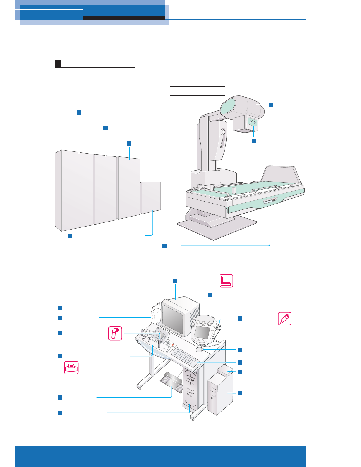
1 System Overview
Automatic
collimator
FPD
(Flat panel detector)
Hand switch
Speaker unit
Microphone
Diagnostic table console
Foot switch
X-ray high voltage
generator console
Image monitor
Exposure switch
Mouse
Keyboard
Control cabinet
(Diagnostic table)
Subsystem control cabinet
(Flat panel detector)
Diagnostic table
Selector
(attached mouse,
monitor and keyboard)
PCU
(FPD control)
Control cabinet
(Flat panel detector)
Control cabinet
(X-ray high voltage generator)
X-ray
tube unit
Control cabinet
(Digital image processor)
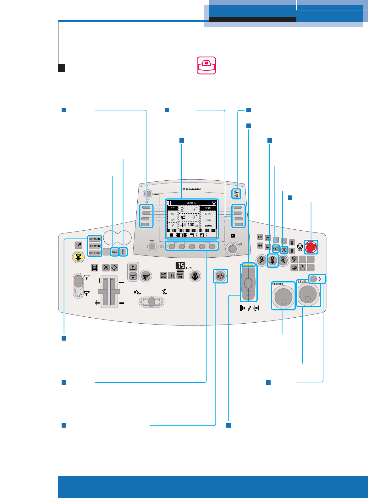
1
Configuration
System Overview
Page 5
5
M517-E077A
1 System Overview
R1 - R4
Selects the APR.
Table to the vertical position
T
able to the
horizontal position
SID selector switches
Display panel
Exposure indicator
Exposure switch
Reverse the image
vertically
Reverse
the image
horizontally
Stop switch
Adjusts the contrast
of the image.
Adjusts the
brightness of image.
Joystick
Table/imaging unit control lever
F1 - F5
Sets up the Subdivisional Acquisition
for SPOT radiography.
Sets up the tomography parameter
for tomography (Option).
Fluoroscopy selection switch
Oblique projection
center switch
L1 - L4
Selects the magnifi cation
size of FPD.
Diagnostic table console
Page 6
6
M517-E077A
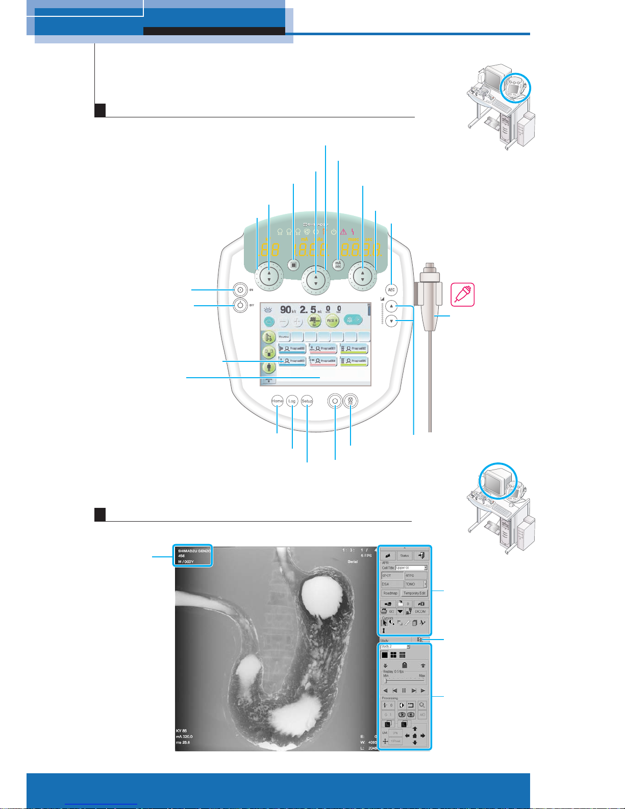
1 System Overview
1 2 3
+5
0
-5
Focus button
kV up/down button
(Adjust in small increments)
kV shuttle (Adjust in large increments)
Power ON button
Power OFF button
Home button
Log button
Setup button
mA/mAs up/down button
(Adjust in small increments)
mA/mAs shuttle
(Adjust in large increments)
sec up/down button
(Adjust in small increments)
sec shuttle
(Adjust in large increments)
AEC button
Hand switch
Density up/down button
X-ray radiography button
Radiography preparation button
mA/mAs switch button
Standard control
panel
Expanded control
panel
Standard control
panel/thumbnail
display button
Patient
information
Radiography program button
Touch panel
Digital image processor main screen
X-ray high voltage generator console
Page 7
7
M517-E077A
1 System Overview
Start study P.13
Choose type of study P.15
Set Fluo/Rad condition P.16
Fluoroscopy/Radiography P.17
Print image P.20
Send by DICOM P.23
Close study P.24
Shut down system P.9
∗ Repeat as required.
Start up system P.8
Calibrate FPD P.10
Operation flow chart
Page 8
8
M517-E077A
2 System startup and shutdown
1
Verify
● Image monitor of digital image
processor and peripherals are turned
OFF.
2
Press
will be illuminated after approx.
2 seconds.
Image monitor, peripherals, and
control cabinet are turned ON.
1 2 3
+5
0
-5
Digital image processor
While the system is running the
power up self-testing routine, a
splash screen appears.
Startup is completed when the
following screen appears.
X-ray high voltage generator console
Stand-by indicator
Main image area
2
System startup and shutdown
Startup
Page 9

9
M517-E077A
2 System startup and shutdown
1
Close active study
1 Click on the Standard control
panel.
A confirmation dialog appears.
2 Click [OK].
The study is closed.
2
Close the application
program
1 Click on the Standard control
panel.
A confirmation dialog appears.
2 Click [Yes].
The system will be automatically
shut down and the control
cabinet will be turned OFF.
X-ray high voltage generator console
3
Turn OFF the X-ray high
voltage generator
Press OFF.
ON lamp is turned off, and then
OFF lamp is turned ON.
After pressing the OFF button on the X-ray high voltage generator
console, do not press the ON button for at least 10 seconds. If you
do, the system may not operate properly.
Caution
Digital image processor
1 2 3
+5
0
-5
Shutdown
Page 10
10
M517-E077A
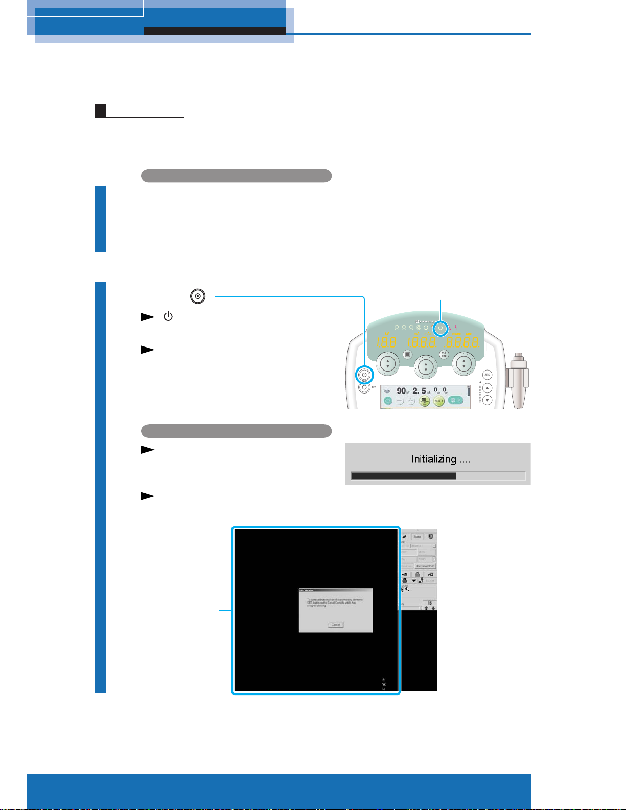
2 System startup and shutdown
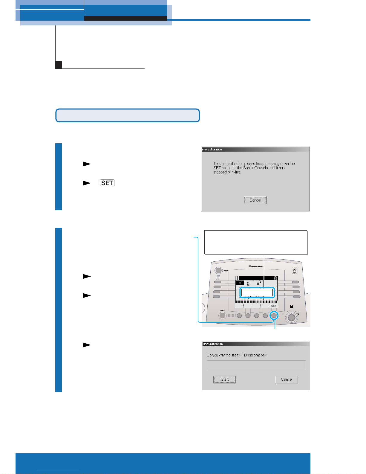
This operation maintains the quality of fl uoroscopy/radiography images. Be sure to perform
the FPD calibration once a day after system startup. Verify that no substance is located on
the diagnostic table during FPD calibration. Approx. 15 minutes is required to complete the
FPD calibration.
Auto FPD calibration on system startup
Perform when the system starts up.
1
Start up the system
After system startup, an FPD
calibration dialog appears.
A on diagnostic table console
blinks, and the message appears.
2
Press and hold the [SET]
on the diagnostic table
console
The diagnostic table moves to
calibration position.
It sounds beep when the diagnostic
table arrives in calibration position.
An FPD Calibration start dialog
appears.
FPD calibration
Press [F5 : SET] to move Table to
calibration starting position.
Press [F5 : SET] to move Table to
calibration starting position.
[SET]
Page 11

11
M517-E077A
2 System startup and shutdown
3
Click [Start]
An FPD Calibration starts.
[Close] button appears when FPD
calibration is complete.
4
Click [Close]
Make sure there are no personnel in the study room before
performing FPD calibration procedure as the diagnostic table
exposes X-ray during the procedure.
Caution
Page 12

12
M517-E077A
2 System startup and shutdown
FPD Calibration from Right-click menu
Perform while the system is running.
Perform FPD calibration after the study is fi nished because the operation cannot be
performed during study.
1
Right-click on the main
image area
The right-click menu appears.
2
Select [FPD Calibration]
The FPD Calibration dialog
appears.
The following procedures are same
as auto FPD calibration in system
startup steps.
Page 13
3 Enter study
13
M517-E077A
Enter the patient information to start study.
3
Enter study
Defining usual study
1
Open Patient List window
1 Click on the Standard control
panel.
A Patient List window appears.
2 Click [New].
A Patient Information window
appears.
2
Enter patient information
● Patient Name
● Patient ID
● Patient DOB
…
Fields indicated by an asterisk (∗)
are required.
3
Click [Open]
The Patient Information window is
closed, and then the study starts.
A patient’s information appears on
the upper left corner of main image
area.
Page 14

14
M517-E077A
3 Enter study
The system automatically sets a tentative data such as a patient’s name and patient
ID when the time is pressing or the patient’s information is unknown during emergency
medical service.
Defining patient information in an emergency
1
Open Patient List window
1 Click on the Standard control
panel.
A Patient List window appears.
2 Click [Emergency]
.
The Patient List window is
closed, and then the study
starts.
The patient’s information appears
on upper left of the main image
area.
The following patient information
is automatically defined.
• Patient Name (Last Name):
ELNMyyyymmdd
↓
Current year/month/date is set.
• Patient Name (First Name):
EFNMhhmmss
↓
Current hour/minute/second is set.
• Patient ID:
EPIDyyyymmdd
-hhmmss
↓
Current year/month/date-
hour/minute/second is set.
• Sex: OTHER
The tentative data must be
corrected after the study.
ELNM20060501 EFNM121342
EPID20060501-121342
OTHER
Page 15

3 Enter study
15
M517-E077A
Choosing types of study
1
Choose [Cell Title]
according to types of
study
The top 4 APRs according to type
of study appear.
Diagnostic table console display panel
The top 4 APRs registered by
digital image processor appear.
Page 16

16
M517-E077A
4 Fluoroscopy/Radiography
4
Fluoroscopy/Radiography
Setting radiography condition
1
Select APR
Diagnostic table console
Press any key of R1 - R4 on the
console to select APR.
Digital image processor
The APRs selected on the
diagnostic table console appear on
the Standard control panel.
X-ray high voltage generator console
The radiography program
associated with APR is displayed.
2
Select the magnification
size
Press any key of L1 - L4 on the
console to select FPD magnification
size.
R1 - R4
L1 - L4
APR Cell titleRadiography item
Page 17

4 Fluoroscopy/Radiography
17
M517-E077A
SPOT radiography/SERIAL radiography
Set the radiography condition prior to radiography as necessary.
Radiography
1
Verify
● Patient information
● Types of study
(APR cell title and radiography item)
2
Select
1 Select APR for SPOT or SERIAL
radiography.
SPOT radiography
2 Select Subdivisional Acquisition
format from [F1] - [F4].
The selected Subdivisional
Acquisition format is displayed
inverted.
3
Fluoroscopy
1 Verify that the fluoroscopy selection
switch
illuminates.
The X-ray is not exposed when the
fluoroscopy selection switch
is
not illuminated even if the foot switch
is pressed. Press the fluoroscopy
selection switch
to light.
2 Press down the foot switch.
The exposure indicator illuminates.
The fluoroscopy image appears on the
main image area of digital image processor.
4
Expose
Press exposure switch.
SERIAL radiography
X-ray exposure terminates after images are acquired within preset time.
Acquired images are serially displayed (Auto Replay: ON) or the last
image appears (Auto Replay: OFF) after exposure.
Releasing the exposure switch stops the image acquisition during exposure.
F1 F2 F3 F4
Confirm the [IBS] and [Pulse
Fluoroscopy] are selected
on touch panel of X-ray high
voltage generator console
([IBS] lights up when ON).
IBS
Pulse Fluoroscopy
Note
Page 18

18
M517-E077A
4 Fluoroscopy/Radiography
DSA radiography (Option)
1
Verify
● Patient information
● Type of study
(APR cell title and radiography item)
2
Select
Select APR for DSA radiography.
3
Fluoroscopy
1 Confirm that the fluoroscopy selection switch illuminates.
The X-ray is not exposed when the fluoroscopy selection switch is
not illuminated even if the foot switch is pressed. Press the fluoroscopy
selection switch
to light.
2 Press down the foot switch.
The exposure indicator illuminates.
The fluoroscopy image appears on the main image area of digital image
processor.
4
Prepare injector
5
Expose
Press and hold down the hand switch.
Mask images followed by live images are acquired (automatically).
The DSA image appears on the main image area of digital image processor.
X-ray exposure terminates after images are acquired within preset time.
Releasing the exposure switch stops the image acquisition during
exposure.
Page 19

4 Fluoroscopy/Radiography
19
M517-E077A
Digital tomography (Option)
1
Verify
● Patient information
● Types of study
●
must be selected.
2
Select
Select APR for tomography.
3
Set up parameters
1 To select a parameter,
press [F2: Select].
2 To change the value,
press [F3: Value] or [F4: Value].
The exposure time is automatically
determined when the diagnostic table
moves to the starting point of tomography .
4
Move diagnostic table
to starting point
Press [F5: SET] until the key is highlighted.
Press [F1: Cancel] for canceling the exposure operation.
5
Exposure
Press and hold down the hand switch.
The tomography image appears on the main image area after each exposure.
Hold down the hand switch until the table stops.
When the hand switch is released during the process, the images for which the
exposures have been completed are stored on the hard disk.
Returning angle of X-ray tube unit
Press the oblique projection center switch .
TEST
RUN
● Layer height
● Pitch
● Number of exposure
(serial mode)
F1 F2 F3 F5F4
Page 20
20
M517-E077A
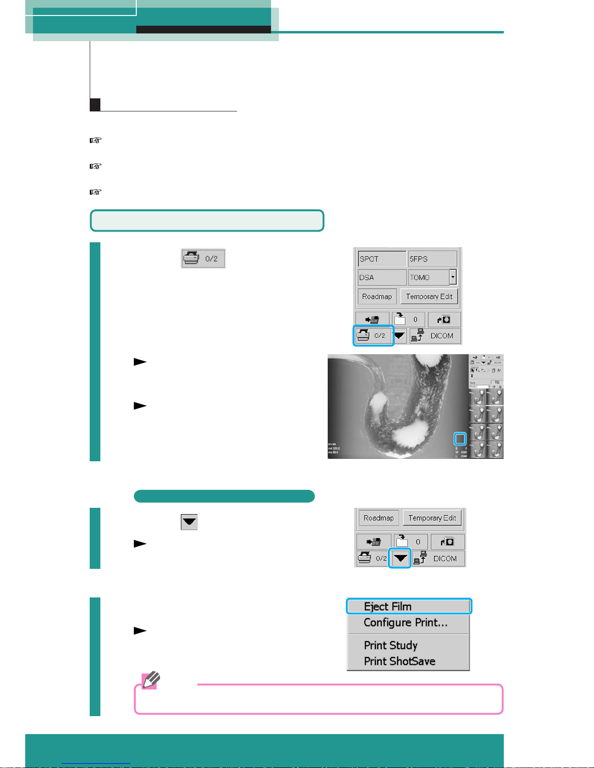
5 Process images
Do one of the following to print images.
Click [Print Image] : Confi rm the actual image displayed on the main image area and
print the image.
Select from right-click menu: Confi rm the actual image on the main image area and
select/deselect to print the image.
Select from Patient List: Entire patient fi le or specifi c study can be printed.
5
Process Images
Printing images
Print by [Print Image]
1
Click
A mark "S" appears in the lower
right corner on the main image
area.
The images will be printed when
the number of frames reaches the
quantity of film format (up to 12
frames).
S
Print image without sending specific quantity
2
Click
The Print Layout menu appears.
3
Select [Eject Film]
The images will be printed.
Printed images are saved in the "Print ShotSave" folder.
Note
Page 21

21
M517-E077A
5 Process images
Print from Right-click menu
1
Right-click on the main
image area
The Right-click menu appears.
2
Select [Print Select]
H
A mark "H" appears in the lower
right corner of the main image
area.
The mark "H" appears when the
image to be printed is selected.
To delete the mark "H", select
[Print Select] from Right-click menu
again.
3
Select [Print Start]
The image will be printed.
Page 22

22
M517-E077A
5 Process images
Print from Patient List
1
Click on the
Standard control panel
The Patient List window appears.
2
Select patient file or
study
Patient
Study
Print
Study
Print
Patient
Either the patient file or specific
study can be selected from Patient
List window.
3
Click either [Print Patient]
or [Print Study]
The Configure Print Settings dialog
appears.
Clicking [Print Patient] , all
images in the selected patient file
are printed.
Clicking [Print Study] , all
images in the selected study are
printed.
4
Change or set the
configurations
5
Click [OK]
All images are printed.
Page 23

23
M517-E077A
5 Process images
The images including study can be sent to CD-R or DICOM network (Option) in DICOM
format in the following ways.
CD-R
• Export to DICOM CD from Patient List
DICOM network (Option)
• Manual DICOM Send • Auto DICOM Send
• DICOM Send from Patient List • DICOM Send from Thumbnail
This clause describes only Manual DICOM Send.
For more DICOM exporting, refer to "DAR-8000f Operation Manual".
Sending by DICOM function
Manual DICOM Send (Option)
For manual DICOM send, open the patient fi le including image and allow that image to be
displayed on the main image area.
1
Click on the
Standard control panel
The DICOM menu appears.
2
Choose [Send Study] or
[Send ShotSave]
Clicking [Send Study] sends the
entire image in selected study.
Clicking [Send ShotSave] sends
images in ShotSave folder.
The Archive Destinations dialog appears.
3
Select the destinations
4
Click [OK]
The Archive Destinations dialog is closed
and a confirmation window appears.
5
Click [OK]
The image or patient files are sent.
The patient file is closed.
Page 24

24
M517-E077A
6 Close Study
Close Study
6
Closing active study
1
Click on the
Standard control panel
A confirmation dialog appears.
2
Click [OK]
The patient file is closed.
Page 25

25
M517-E077A
7 Troubleshooting
Troubleshooting
7
Emergency stop/Recovery
Emergency stop the diagnostic table operation
Press the stop switch on either the diagnostic table console or diagnostic table.
● Diagnostic table console
● Diagnostic table
Recovery from emergency stop
To recover from emergency stop, be sure to turn the stop switch clockwise.
Ensure to pause 10 seconds or more between halt and recovery.
Caution
Page 26

26
M517-E077A
7 Troubleshooting
• X-ray high voltage generator console
When the system detects a fault, an error message appears on X-ray high voltage
generator console.
Touch the
key to close the message screen, and then take action described
below for the error message.
Error messages
Messages related to the X-ray high voltage generator
(fault indicator) on the console illuminates and one of the following error messages
appears.
The system cannot expose while these messages are displayed.
Message Meaning
Radio Over Current
Radiography tube current
exceeded set value
+ 200 mA.
Measured kV OVER
Measured tube voltage
exceeded permitted range.
Starter ERR
Starter is in abnormal
situation or condition.
Starter is not working
Starter is not working when
fl uoroscopy.
I.F. OVER
Abnormal fi lament heating
current.
Line Voltage OVER
Supply voltage exceeded
permitted range.
Charge Volt ERR
Abnormal charging voltage of
primary smoothing capacitor.
Power Down
Abnormal control circuit
supply voltage.
H. V. T Not Connected
Abnormal connection to
high-voltage transformer.
Arcing Trouble Repeated arcing occurred.
Procedure
If this message appears
repeatedly, contact
Shimadzu service
representative.
Contact Shimadzu service
representative.
Page 27

27
M517-E077A
7 Troubleshooting
Messages related to the radiography conditions
(caution indicator) on the console illuminates and one of the following error
messages appears.
The system cannot expose while these messages are displayed.
Message Meaning
mAs OVER
mAs value exceeded set
value by 800 mAs.
mAs too small
mAs value was less than
0.5 mAs. Or, tube current
was below minimum value
for mAs setting method.
Emission OVER
Emission characteristics out
of range.
Generator Load OVER Equipment ratings exceeded.
mAs/Time OVER
mAs value too large and
radiography time exceeded
10 sec. Or, radiography time
exceeded permitted range.
2 control range OVER
Setting out of range for mAs
setting method.
Procedure
Change the set value.
Increase radiography
tube voltage or reduce
radiography tube current.
Decrease radiography tube
voltage or radiography tube
current.
Reduce the set value of
mAs or sec.
Reduce the set value.
Messages related to the radiography conditions
One of the following error messages appears.
The system cannot expose while these messages are displayed.
Message Meaning
HU OVER Predicted
Value predicted to go out
of range if the heat units
increase from the current
heat unit value according to
the set radiography.
HU Full Stored
Heat units reached the
permitted limit.
Thermal OVER
X-ray tube unit temperature
exceeded the permitted limit.
Procedure
Change the radiography
conditions or cease
operation until heat unit
value reduces.
Cease operation until heat
unit value reduces.
Page 28

28
M517-E077A
7 Troubleshooting
Error messages at power ON
Message Meaning
Panel Battery WARNING
The data recording battery in
the operation panel must be
replaced soon.
Cabinet Battery WARNING
The data recording battery in
the control cabinet must be
replaced soon.
Panel Battery EMPTY
The data recording battery in
the operation panel is empty.
Cabinet Battery EMPTY
The data recording battery in
the control cabinet is empty.
X-ray switch ERR
The radiography button
remains ON.
Fluo switch ERR
The fl uoro foot switch
remains ON.
Procedure
Contact Shimadzu service
representative.
Messages related to Communication (Option)
(caution indicator) on the console illuminates and one of the following error
messages appears.
The system cannot expose while these messages are displayed.
Message Meaning
Communication ERR
Received radiographic
conditions cannot be set for
the equipment.
Procedure
Change the setting at the
external instrument.
Other messages
(caution indicator) on the console illuminates and one of the following error
messages appears.
The system cannot expose while these messages are displayed.
Message Meaning
Door/Interlock
The examination room door
is open.
AEC OVER
AEC failed and AEC backup
was used during AEC
radiography.
The fl uoroscopy table is not
prepared
The fl uoroscopy table is not
prepared due to incorrect
position of X-ray tube.
Procedure
Close the door.
Increase radiography
tube voltage or extend the
radiography time.
Confi rm the diagnostic
table confi guration.
Page 29

29
M517-E077A
7 Troubleshooting
• Diagnostic table console
Message Meaning
Position Detect Error XXX
Position detect error in
operating parts
Position Error XXX Potentiometer break detect
Motor Error XXX Motor error
Procedure
Reset by pushing STOP
switch, or re-startup the
system. If the system is not
restored, contact Shimadzu
service representative.
Page 30

30
M517-E077A
7 Troubleshooting
In case of power failure due to lightning, UPS (Uninterruptible Power Supply) contained
in control cabinet detects the power failure, and then automatically shuts down the FPD
(PCU). Without automatic startup for FPD (PCU) after power failure recovery (backup by
UPS), perform manual startup.
Actions after power failure
1
Turn ON the system
"Startup" P.8
2
Turn ON the power
switch of PCU
Application software "Xcat" for FPD
control starts up automatically.
Approx. 5 minutes is required to
complete the startup.
3
Shut down the system
Turn ON the system
again
4
Verify the FPD power
control condition
Click [Tool], and then click [Power…].
A HV Power Control dialog
appears.
● Verify that the check boxes of
[Synchronize with the host system]
and [Enable timer control] are filled.
Note
Battery backup time by UPS is approx. 3 minutes.
It sounds beep from control cabinet while the power is being backed up by UPS.
If the power fails because backup time for UPS expires, call a Shimadzu service
representative.
Page 31

Page 32

TOKYO OFFICE
3, Kanda-Nishikicho 1-chome, Chiyoda-ku, Tokyo 101-8448,
Japan
Phone: 81(3)3219-5641 FAX: 81(3)3219-5710
Cable Add.: :SHIMADZU TOKYO
Overseas Telex No.: 0232-3291 (SHMDT J)
KYOTO OFFICE
1, Nishinokyo-Kuwabaracho, Nakagyo-ku, Kyoto
604-8511, Japan.
Cable Add.: SHIMADZU KYOTO
Overseas Telex No.: 05422-166 (SHMDS J)
SHIMADZU EUROPA GmbH
Albert-Hahn-Strasse 6-10, D-47269 Duisburg, F.R. Germany
Phone: 49(203)7687-0 Fax: 49(203)7666-25
 Loading...