

Page 1

228-30179
DIFFERENTIAL REFRACTIVE DETECTOR
RID-1
OA
FOR
SHIMADZU
HIGH
-
PERFORMANCE
LIQUID
CHROMATOGRAPH
USER’S
MANUAL
Read the instruction manual thoroughly before you use the product. Keep
this
instruction
manual
with care
so
that you can use it any time you need it.
SHIMADZU
CORPORATION
CHROMATOGRAPHIC & SPECTROPHOTOMETRIC
INSTRUMENTS DIVISION
KYOTO,
3APAN
Page 2

Copyright 0 Shimadzu Corporation
1995.
.
All rights are reserved, including those to reproduce
this
publication or
parts
thereof in any
form without permission in writing from Shimadzu Corporation.
Information in this publication is subject to change without notice and does not represent
a
commitment on the part of the vendor.
Any errors or omissions which may have occurred in this publication despite the utmost care
taken in its production will be corrected
as
soon
as
possible, but not necessarily immediately
upon detection.
Note that Shimadzu does not have any obligation concerning the effects resulting from the
application of the contents of this manual.
MS, MS
-
DOS, Microsoft and Visual Basic are registerd trademarks, and Windows is
a
trademark of Microsoft Corporation
in
the USA.
IBM is a registerd trademark
of
International Business Machines Corporation in the USA.
TrueType
is
a
registerd trademark of Apple Computer, Inc in the USA.
Page 3

The
RID-1
OA
is the differential refractive index detector for the high-performance liquid
chromatograph.
In
order to operate the unit safely, strictly observe the following points.
1.
Do
not
use
the unit for any purpose other than the above mentioned analysis.
2.
Follow the procedures described in the instruction manual.
3.
Observe the warnings and cautions.
4.
Do
not disassemble
or
modify the unit without approval
from
Shimadzu. Failing to do
so
may lead to a dangerous situation or damage of the unit.
5.
For internal repair of the product, contact your Shimadzu Service Representative.
6.
The pink-color pages and the meshed parts are for our service engineers, and are not
intended for our clients.
Do
not attempt installation of the instruments
as
serious damage
could result.
WARNING IN
THE
INSTRUCTION MANUAL
This instruction stipulates the content of warnings as follows:
-1
Applied in a case that could result in death or serious injury.
-1
Applied in a case that could result in slight injury or physical
damage.
-1
Applied for improvement of operating efficiency or help in
understanding.
I
Page 4
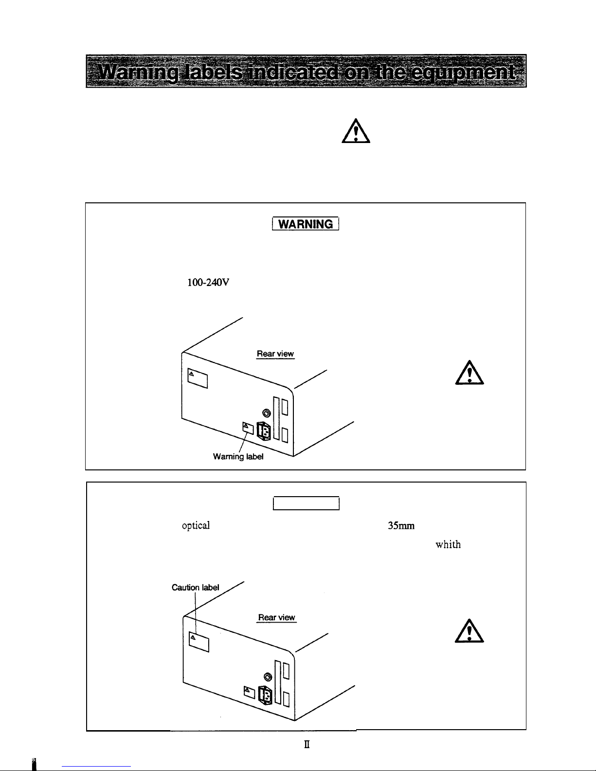
For safety
of
operation, this unit is provided with
the
A
mark
at the portion where special
When operating the
parts
where
this
mark
is
indicated, exercise
special
caution
after
reading
cautions are required.
the
manual.
Replacement
of
fuses
This
unit uses the
following
fuse. Be sure to replace the fuse
of
same
type
and
capacity.
Rated voltage
:
100-24OV
Part
NO.
072-01652-23 250V 5AT
I
CAUTION
I
Do
not bend the optical cable for remote control with the radius
of
35mm
or less.
Bending it with the radius smaller than 35mm may damage the cable,
whith may cause
malfunction
of
the
unit.
Page 5
m
VAOS
I
AOX-022
VAOSI
A02
I
96-000ZE-822
26-0002€-822
VAOS
I
hpedea
A001
16-000Zf-822
a3NlOS
JaMOd
'ON
lred
Page 6

8.
Solvent
not
usable
HFIPA
(Hexafluoroisopropyl alcohol) affects the materials used in the flow path and
deteriorate the strength of the material. In the worst case, pipe may explode and high
-
pressure solvent scatters.
As
it is very dangerous, never
use
HFIPA.
9.
Others
The equipment should not be exposed to direct sunlight or strong air currents.
It
is
also
recommended to install in a room where temperature fluctuation
is
small.
N
Page 7
Liquid chromatography using flammable organic solvents as mobile phase requires proper care
against
fire,
explosion, etc. Pakcularly, among various possible accidents, those caused by static
electricity are difficult to anticipate, and tend to occur only with unexpected conditions which
often make countermeasures insufficient.
At a site where preparative liquid chromatography is practiced, a large amount of flammable
substances may be used. Therefore, once an accident happens, it could lead to tremendous
damage.
The mechanism of accident caused by static electrical discharge and preventive measures are
described below. Take due care in safety measures in handling of equipment.
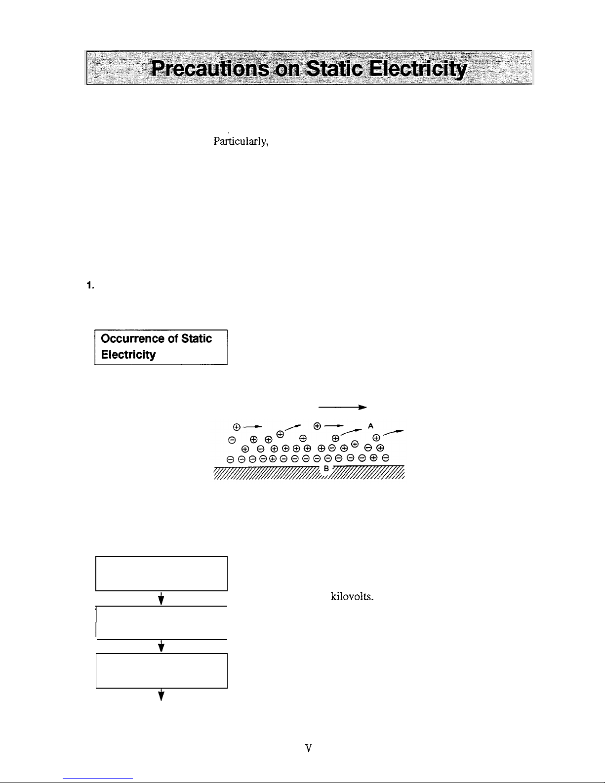
1.
Mechanism
of
Static Electrical Discharge Accident (Example)
Accidents caused by static electricity take place through the following processes.
When liquid is fed at high speed through a small
-
diameter
tube like the pipe of a liquid chromatograph, static electrical
charge occurs by friction between solid and liquid
as
shown in
Fig.
1.
Occurrence
of
Static
Electricity
1
$
-
Flowing liquid
A
Solid
body
A
:
Electric charge
moving with
flowing liquid
B
:
Electric charge
being fixed
to
the
solid surface.
Fig. 1 Occurrence
of
Static Electricity by Friction between Solid and Liquid
Charging and storage
of
static electricity
t
1
Energy release by
1
I
discharge
I
3.
Ignition
of
combustible
substances
f
When the charged liquid is collected in an insulated vessel,
the static charge accumulates gradually, and the voltage can
easily reach
a
few kilovolts.
If
some other conductive object
is
brought near the vessel,
electricity is discharged at a certain distance from the vessel
releasing heat energy.
If flammable gas of sufficient concentration exists nearby,
ignition is caused by this energy.
Page 8
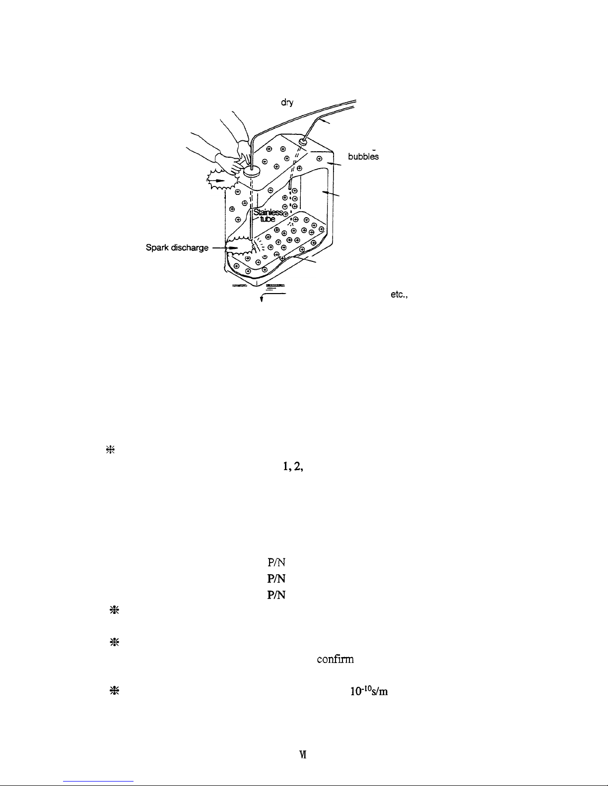
If
air drv
\
Liquid is flowing at high
speed
through a
small
diameter tube.
*Charge is easily accumulated if
bubbles are included in the liquid.
Insulated vessel
(like polyethylene)
Spark discharge
-
””;”oyc
I
Ill
/
Inflammable gas is stored in the
head space
of
the vessel.
(\
n\
Inflammable organic solvent is
charged
to
a great extent.
e
- - -
-
Floor covered
with
rubber, etc.,
provides unwanted insulation.
Fig. 2 Conditions which may cause Accidents
2.
Preventive Measures against Accidents
The principal preventive measure is the prevention of “charging and storage of static
electricity” among those items shown in “Mechanism
of
Static Electrical Discharge
Accident.” The preventive measures are shown below. It is recommended to exercise two
or more measures simultaneously.
3K
Particularly when a large quantity of flammable solvent is held in a large vessel,
be
sure
to observe the preventive measures
1,2,
and
3.
Preventive measure
1.
Use metallic (conductive) waste liquid vessel which is well grounded.
This
releases the
charge of the waste liquid and vessel to ground.
The following items are available.
(1)
Grounding
wire
with clip P/N
228-21353-91
(2)
Metallic
18
liter can
P/N
038-00044
(3)
Metallic 4 liter can
P/N
038-00043-01
3K
+E
Be sure to ground the vessel properly. Disconnecting of grounding wire or poor
grounding defeat the purpose of using
a
metallic vessel.
There are some metallic cans which have no conductivity
due
to
an
oxidized coating
or lacquer on their surface. Be
sure
to
confirm
the grounding
of
vessels by a tester
before application.
When a liquid with almost no conductivity (of
10-lOs/m or less) is discharged into the
vessel, it is necessary to
mix
it with another liquid with some conductivity. (The other
liquid can be placed in the vessel
in
advance.)
%
Page 9
Preventive measure
2.
Minimize the clearance
of
both inlet and outlet
of
vessel to prevent flame from entering the
vessel.
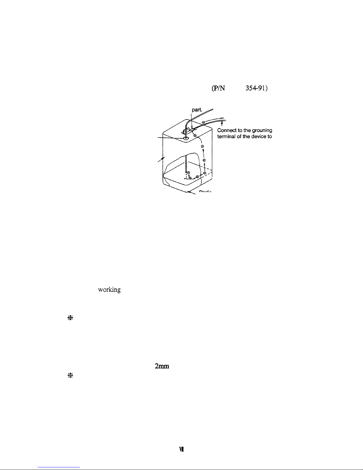
(1)
Cap with three holes for
18
liter and 4 liter cans
(P/N
228-21
354-91)
is available.
Connect clip to metallic
Minimize clearance
by
attaching a cap.
ground the metallic vessel.
Metallic
18
litter can
(A
plated can is recommended.)
Static electricity
of
the liquid
is released via vessel.
Fig. 3 Anti-Static Electricity Measures for Vessel
Preventive measure
3.
Do
not approach the vessel with charged objects including the human body.
Charging prevention measures for human body
a)
b) Grounding
of
human body
c) Make
working floor conductive
Prevention of charging of shoes and clothes
Suitable products to be used for those measures a), b), and c) are available on the
market.
When persons who use no charge prevention measures approach dangerous sections,
they have to be grounded beforehand. (For example, they should contact grounded
metal by hand.)
%
Preventive measure
4.
Use pipes with inner diameter of
2mm
or more for waste liquid line for large flow rates.
3%
Inclusion
of
bubbles in the
tube
may increase the amount of charging by ten times.
Check that there is no inclusion
of
air
via
tube
joints.
Page 10

Preventive measure
5.
When it is impossible to use a conductive vessel, use caution in the following points.
a)
Set the vessel
so
that the pipe outlet will be placed below the liquid
level
in the
vessel. Or, dip a grounded metal (ex. pipe connected
to
the main body of device) in
the liquid.
This
method is not effective
for
liquid with small conductivity (10-I0s/m
or
less).
Use
a
vessel
of
the
smallest possible capacity to minimize the damage by
fire
if it
should occur.
Prevent the
room
from
being
dry.
Humidity of
65% or
more has charge prevention
effects.
+E
b)
c)
a
Page 11
1ChapterlI
General
1.1
Outline
..........................................................................................................
1-2
1.2
Features
........................................................................................................
1-3
1.3 Principle
of
Measurement
.............................................................................
1-4
1.4
Row Schematic
............................................................................................
1-6
1
Chapter2 1 Parts List
2.1 Parts and Accessories
...................................................................................
2-2
-1
Component Location and Function
3.1 Front View
....................................................................................................
3-2
3.2 Interior
of
Front Cover. Right Side
..............................................................
3-3
3.3 Rear View
.....................................................................................................
3-4
I
Chapter4 1 Installation
4.1 Basic Installation Requirements
...................................................................
4-2
4.2 Example
of
System Layout
..........................................................................
4-3
4.3
Stacking Modules
.........................................................................................
4-4
4.4 Electrical Connections
..................................................................................
4-5
4.6 Connecting the Recorder and Integrator
.......................................................
4-11
4.7
4.5 Plumbing Connections
..........................................
:
......................................
4-6
Connecting the Drain Tube
for
Solvent Leakage
...........................................
4-13
1-1
Operation
5.1
Precautions
for
Operation
.............................................................................
5-2
5.2 Fundamentals
of
Operation
..........................................................................
5-3
5.3 Plumbing
of
the Flow Selection Block
.........................................................
5-13
5.4
5.5
Creating and Executing
Tie
Programs
.......................................................
5-16
Additional Functions (AUX
-
FUNC)
............................................................
5-21
1
ChaDter
6
I
Initial Performance Test
6.1
System Performance Check
............................................................................
6-2
-1
Control from External Equipment
7.1 Connection with System Controller SCL-1 OA
.............................................
7-2
7.2 Control
form
the SCL-IOA
...........................................................................
7-3
7.3
Connecting External Input and Output Terminals
........................................
7-10
I
Chapter
8 1 Maintenance
8.1
Cleaning the Flow Lines
...............................................................................
8-2
8.2 Span Adjustment
..........................................................................................
8-3
8.3 Replacement
of
Fuse
....................................................................................
8-7
8.4 Periodical Cleaning
......................................................................................
8-8
Page 12
1-1
Performance Verification
9.1 Component Validation
..................................................................................
9-2
9.1
.
1
Test Procedures
of
Stand-alone Unit
......................................................
9-3
9.1.2
Test Procedures Controlled
from
the
SCL
-
1
OA
......................................
9-5
9.2 System Validation
.........................................................................................
9-9
9.2.1 Test Procedure
of
Isocratic LC System
..................................................
9-9
1-1
Troubleshooting
10.1
10.2
Symptoms. Causes and Remedies
................................................................
10-2
List
of
Error
Messages
..................................................................................
10-4
-1
Specifications
...............................................................................
1 1 . 1
RID-1
OA
Specifications 11-2
[-I
Replacement Parts
12.1
Consumables
and
Repair
Parts
.....................................................................
12-2
12.2 Optional
Parts
...............................................................................................
12-4
rChapterl31
Reference
13.1 Solvent Characteristics
.................................................................................
13-2
.
Page 13

Chapter
1
General
1.1
Outline
.....................................................................................................
1-2
1.2
Features
...................................................................................................
1-3
1.3
Principle
of
Measurement
.......................................................................
1-4
1.4
Flow
Schematic
.......................................................................................
1-6
1-1
RID-1OA
-
Page 14
RID-1OA
is
the
differential refractive index detector for the high
performance liquid
chromatogaph developed as a module
of
the
LC
-
1
OA
series.
The
RID-10A
improves analysis productivity and convenience
of
use like a
UV
detector. Its shortened stabilization time, the fact that
it covers various applications from high sensitivity analysis to
sampling analysis preparation
and
more,
RID-1OA
is much
improved in convenience than conventional models.
Only handling instructions for
RID
- 1 OA
and related accessories
are
described
in
this
instruction manual.
For
handling instructions of
other components, please refer to the pertinent instruction manual.
1-2
-
RID-1OA
Page 15
1.
Excellent
stability
Stabilization time after turning on the power has been shortened to
reduce the waiting time for
start
of
analysis. Excellent stability has
been realized by employing the dual temperature control structure
of
the optical system and by improving the thermal design.
-
0
r
t
By adapting the original four-partitioned photodiode,
this
equipment
now covers the wide dynamic range of various applications from
high
sensitive analysis to large scale preparation of high concentration
samples.
2.
Various
applications
3.
Safety measure
4.
Corresponding to the
LC-1OA
series
The standard model is equipped with a leak sensor which enables
automatic performance
of
operations such
as
stopping the pump in
the early stage of organic solvent leakage.
This
equipment is designed for the
LC
-
1
OA
series to have excellent
operability
as
a
component of the total system, including control
from the
SCL-1OA
and
data
processing in the
CLASS
workstation,
etc.
1-3
RID-1OA
-
Page 16
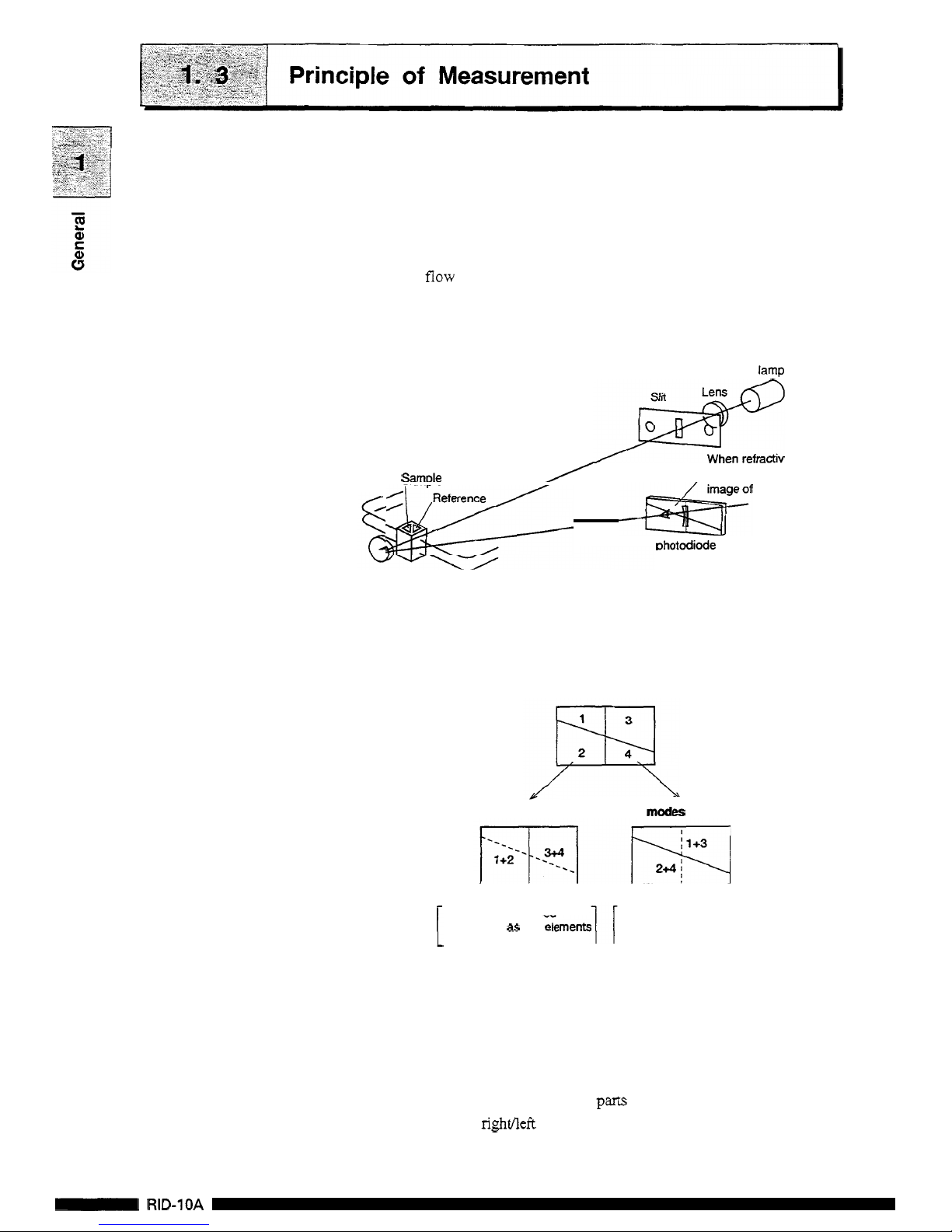
The optical system of this unit is shown in following illustration.
The light radiated from the lamp passes through the lens slit and
through the cell in the form of parallel rays, which is then reflected
by
the
mirror and passed through the cell
to
form an image of the
slit
on
the photodiode.
The
flow
cell consists of the sample side and the reference side.
When
the refractive index
in
the sample side cell varies,
the
image
of the slit moves horizontally.
W
lamp
#
When refractive index
I
When refractive index
,
in the
flow
cell
vanes,
Samole
/
<\-&
~&zf
the
slit
moves.
Dhotodiode
This
unit has a photodiode partitioned in four
as
shown in the figure
below. When selecting a piece of photodiode to use among these
four, the unit is able to provide measurements for both analytical
and preparative work.
In
modes
P
and
L
In
mode
A
1
A
signal is processed
divided into up and down.
regarding
it
as
two
regarding
it
as
two
elements
A
signal is processed
divided into right and left.
Signal processing
in
mode
A
A
signal
is
processed using the right and left portions of the
photodiode
as
individual elements. Data processing is performed as
a two
-
partitioned photodiode divided into right and left.
When the refractive index in the
cell
varies,
the
balance of the incident
light intensity into right and left
parts
of
the photodiode changes. The
change
in
the right/left balance
is
converted into refractive index and
then can
be
recorded.
1-4
-
RID-1OA
Page 17
1.3
Principle
of
Measurement
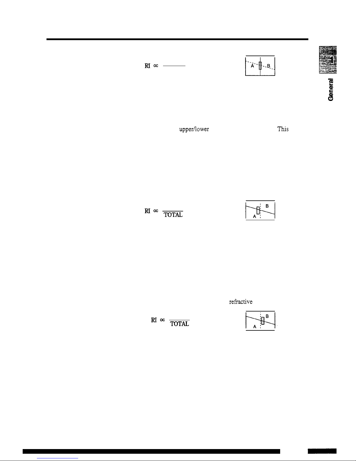
A-B
RIx
TOTAL
Signal processing in mode
P
-
E
a,
Signal processing is performed using the upper and lower parts of
L
Q
the photodiode
as
individual elements. Since the boundary between
the upper and lower parts
is
slanted against a horizontal line, when
an
image of the slit moves horizontally, the balance of the light
intensity
in
the upper/lower parts
of
the diode changes.
This
change
in balance is converted into refractive index. The change
of
the bal
-
ance against the variation
of
the
refractive index is one-twentieth
that
of
mode
A.
In
mode
A,
when the slit image goes beyond the
center line, measurement becomes impossible because the balance
value stops varying, while in mode
P,
measurement is possible
under
these
conditions enabling measurement of a sample with high
concentration.
A-B
TQTU
Signal processing in mode L (An optional
flow
selection
block
is necessary)
Signal processing is performed
as
the same
as
in mode
P,
using
each
of
the upper and lower parts of the diode
as
individual ele
-
ments. However, since the reference side with less flow line resis
-
tance is used
as
the sample cell, the image moves in the reverse
direction
of
that
of
mode
P.
Thus polarity is turned over
before
the
change in balance
is
converted into a refi-active index.
B-A
TOTAL
w.
A
1-5
RID-1OA
-
Page 18

The diagram shows flow lines
in
the RID-10A.
At R flow
OFF
When the R flow switch is
OFT,
the solenoid valve is open at side
A.
The solvent passing through the sample cell flows into the outlet
port, not into the reference cell.
At
R
flow
ON
When the R flow switch
is
ON,
the solenoid valve is open at side
B.
The solvent passing through the sample cell flows into the outlet
port after passing through the reference cell. This
is
used to fill the
sample cell and the reference cell with solvent of equal refractive
index before starting the measurement.
R
flow
ON
Q
!
Outlet
port
Inlet
port
Tubing
volume (At R flow
OFF)
Inlet port to flow cell
63.5
pL
Flow cell volume
9pL
Flow cell to cell outlet port
280.2
pL
S:
Sample
R:
Reference
1-6
-
RID-1OA
Page 19
Chapter
2
Parts List
c
v)
3
2.1
Parts
and
Accessories
..............................................................................
2-2
1
CONTENTS
1
2
-
1
RID-1OA
-
Page 20

1
[Caution]
Part
Name
Signal cable
When connecting the flow line and performing maintenance, be
sure
to use the
parts
described on this page or
“1
2.1,
Consumable
and Repair
Parts
”.
Normal
function
of
the system
is
not
,guaranteed
when
other
parts
are
used.
Parts
No.
Quantity
228-25089-92
1
This equipment consists of the following components. Upon
unpacking,
confirm that all
parts
listed below
are
included
in
your
shipment.
0
RID-IOA
Main Body
Power supply cord
(
120V)
(220-240V)
Optical cable
0
Standard Accessories
071-608 14-
01
1
07 1-608 14-06
070
-
92025-5
1
1
sus
tubing
Teflon tubing
228-22310-00 lm
228-22305-00
50
crn
228- 18495-03 2m
Remote
cable
I
228-28253-91
I
1
Locking plate
Instruction
manual
SC
Coil
ASSY
(220-24OV)
Syringe
Syringe adapter
228-15672-91
Coupling 1.6C
228-16004-03
Male nut PEEK
228- 18565
228
-
1875
1
1
228-301 78
1
228-34050-9
1
1
Drain tubino
kit
I
228-18495-03
I
1
I
2-2
-
RID-1OA
-
Page 21

Chapter
3
Component Location
and Function
3.1
Front
View
...............................................................................................
3-2
3.2
Interior
of
Front Cover,
Right
Side
.........................................................
3-3
3.3
Rear View
................................................................................................
3-4
c
0
(D
0
0
-
c
3-1
RID-1OA
-
Page 22
w
S
Q,
c
0
E
s
0
I
RID-1OA
I
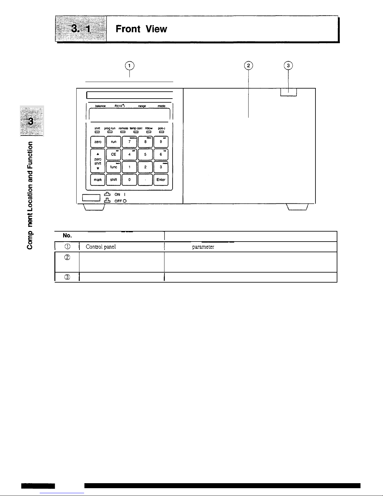
Front cover
The front cover is opened for mounting
and
dismounting of
flow
cell
and
piping.
~ ~~
I
No-
I
Description
7
Function
~~~
1-0
I
controipanel
I
Performs
parasnetex
setting
and
displays
set
values.
I
@
I
Front cover opening
button
1
Press
this
button
to
open the front cover.
3-2
0
RID-1OA
Page 23
ON
I
I%
OFF0
No.
0
0
0
Description Function
Refer
to
page
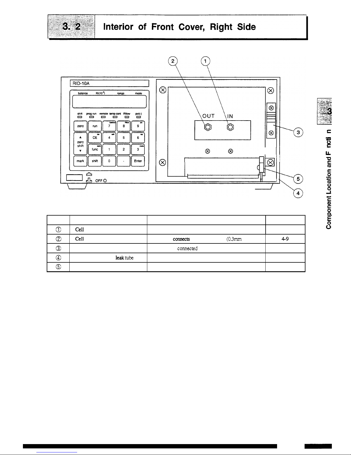
Cell inlet
port
Connects the
tube
from
column.
4-8
I II
@I
@
@
@
HI1
I
Cell outlet
port
Tube
holder
Connection
port
for leak
tube
Normally
COM~C~S
back
pressure
tube
(03mm
ID.
x
Im).
4-9
Secures
the connected
tube.
Connects the leak
tube
to
this
port.
4-13
Solvent
leak
sensor
Detects
solvent leaks and
outputs
an
error signal.
10-4
n
I
\
/
S
0
0
E
3
LL
-
c
3-3
RID-1OA
-
Page 24
E
0
0
E
3
LL
.-
c
No.
3
6
6
@
c9
‘c,
E
Q
Description
Function
Refer
to
page
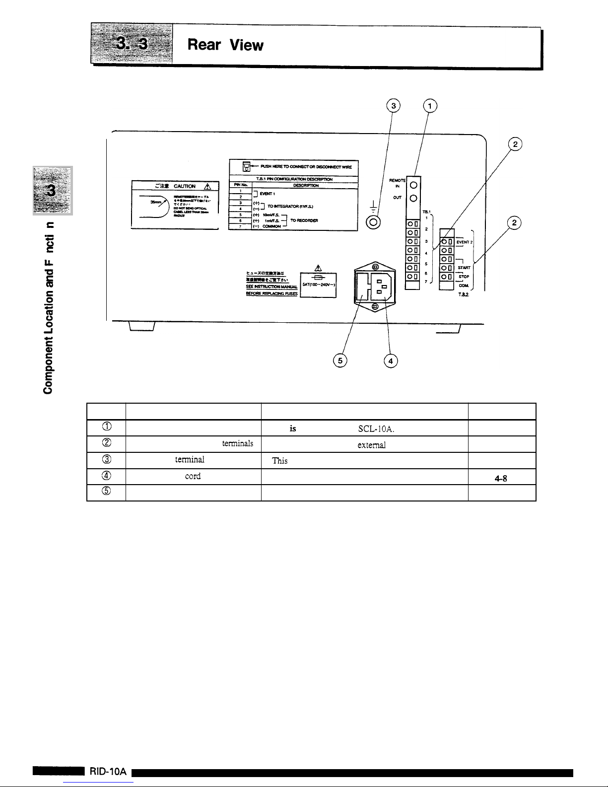
This
is
the connector for
SCL-IOA.
7-2
7
-
16
REMOTE
connector
External
input and output
texminals
Grounding terminal
Power supply cord connector
Fuse holder
These terminals connect
external equipment.
This
terminal
is
used
for grounding.
The power supply
cord
is
connected here.
4-8
Two fuses
are
provided
in
this
holder.
8-7
r
I---
I
i
Ta2
I
I
I
\
I
I
3-4
-
RID-1OA
Page 25

Chapter
4
Installation
~~~ ~~~~ ~
(,,NTENTs
1
4.1
Basic Installation Requirements
.............................................................
4-2
4.2
Example
of
System Layout
....................................................................
4-3
4.3
Stacking Modules
...................................................................................
4-4
4.4
Electrical Connections
............................................................................
4-5
4.5
Plumbing Connections
...........................................................................
4-6
4.6
Connecting the Recorder
and
Integrator
................................................
4
-
1 1
4.7
Connecting the
Drain
Tube for Solvent Leakage
...................................
4-13
4-1
RID-1OA
-
Page 26
Basic Installation Requirements
pAGiiiq
To
take full advantage of the RID-1OA’s performance capabilities
and
to
ensure its operational stability over a long service life,
verify that
the
selected installation site satisfies the following
requirements.
1.
Ventilation
2.
Fire
3.
Sink
Ventilate the room where
the
high-perfomance liquid chromatograph
is located since the solvent used is flammable
andor toxic.
Never use
fre in the same room where the high performance liquid
chromatograph is installed. Also, avoid installation in the same
room of other devices which may spark.
Always
keep
a
fire
extinguisher nearby
in
case of accident.
Install a sink nearby for flushing eyes
or
skin which have been in
contact with solvent.
4.
Corrosive gas and dust
Avoid installation in a place exposed to corrosive
gases
or dust.
5.
Electromagnetic noise
Avoid locations subject to intense magnetic or electromagnetic
fields. Use
an
additional noise filter if power line noise interferes.
6.
Space requirements
This system is designed to be used on a table
or
stand, preferably a
solid and flat surface with
a
depth of 60cm
or
more.
See
“4.2,
Example of System Layout” for typical confi,o;urations of systems
and installation space.
7.
Others
Select
an
installation site with
the
following parameters to maintain
full performance of the system.
(1)
Maintain
room temperature within
4--35”C,
without extreme
fluctuations.
(2)
Avoid direct output of a heater or a cooler.
(3)
Avoid exposure to direct sunlight.
(4)
Avoid locations subject to strong vibrations
or
prolonged
weak vibrations.
(5)
Maintain relative humidity within
45-85%.
4-2
-
RID-1OA
Page 27
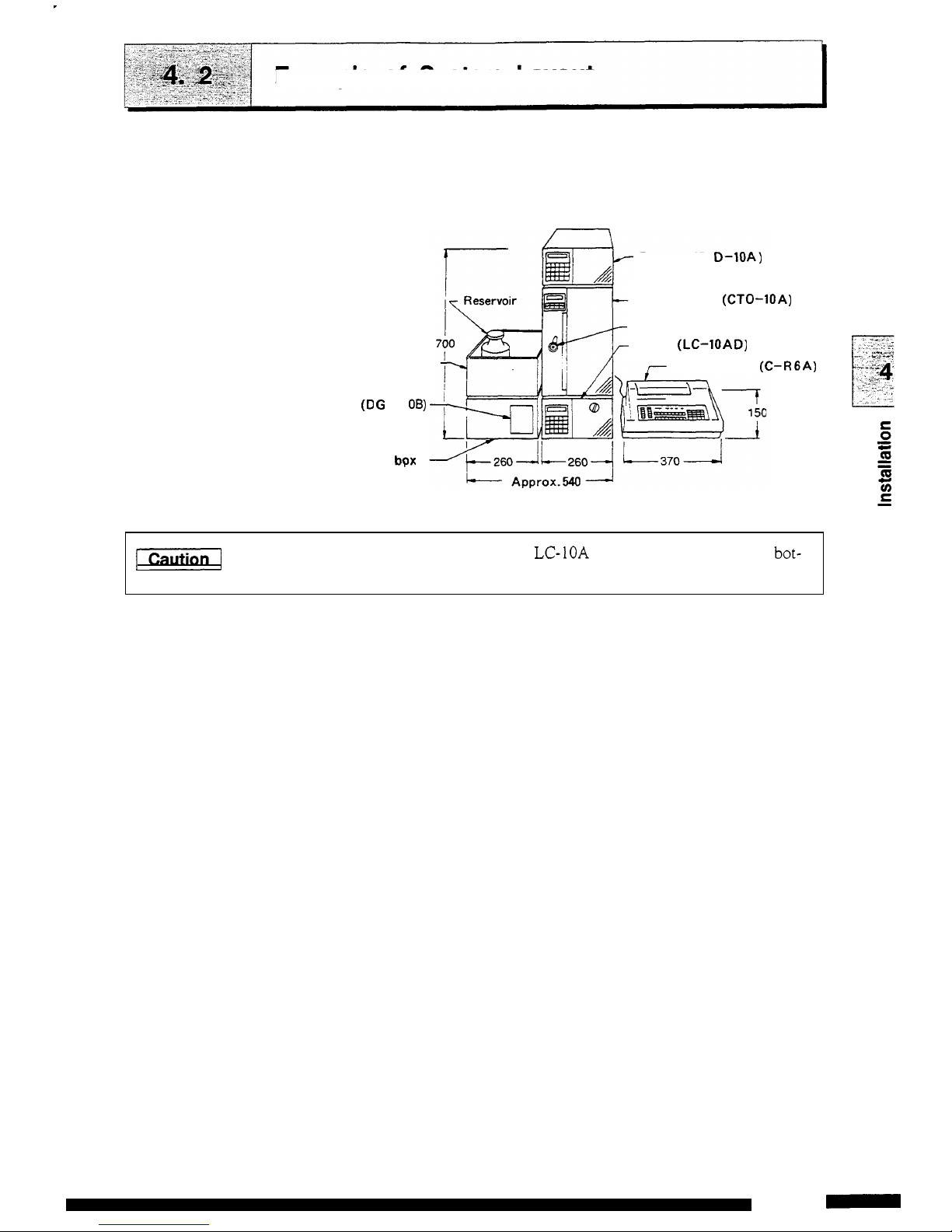
Example
of
System
Layout
Example
of
liquid chromatograph system layout using this equip
-
ment
and
space requirements
are
shown below.
Detector
(RI
0-1QA)
Column oven (CTO-1OA)
Manual injector
(7725)
Pump (LC-IOAD)
Reservoir
box
Chrornatopac (C-RGA)
Degasser
(D
G
U -1
06)
Option
bpx
S
[Caution/
Each component
of
the
LC-1OA
has a little clearance at the bot-
tom. Be careful to keep fingers clear when installing the unit.
4-3
RID-1OA
-
Page 28
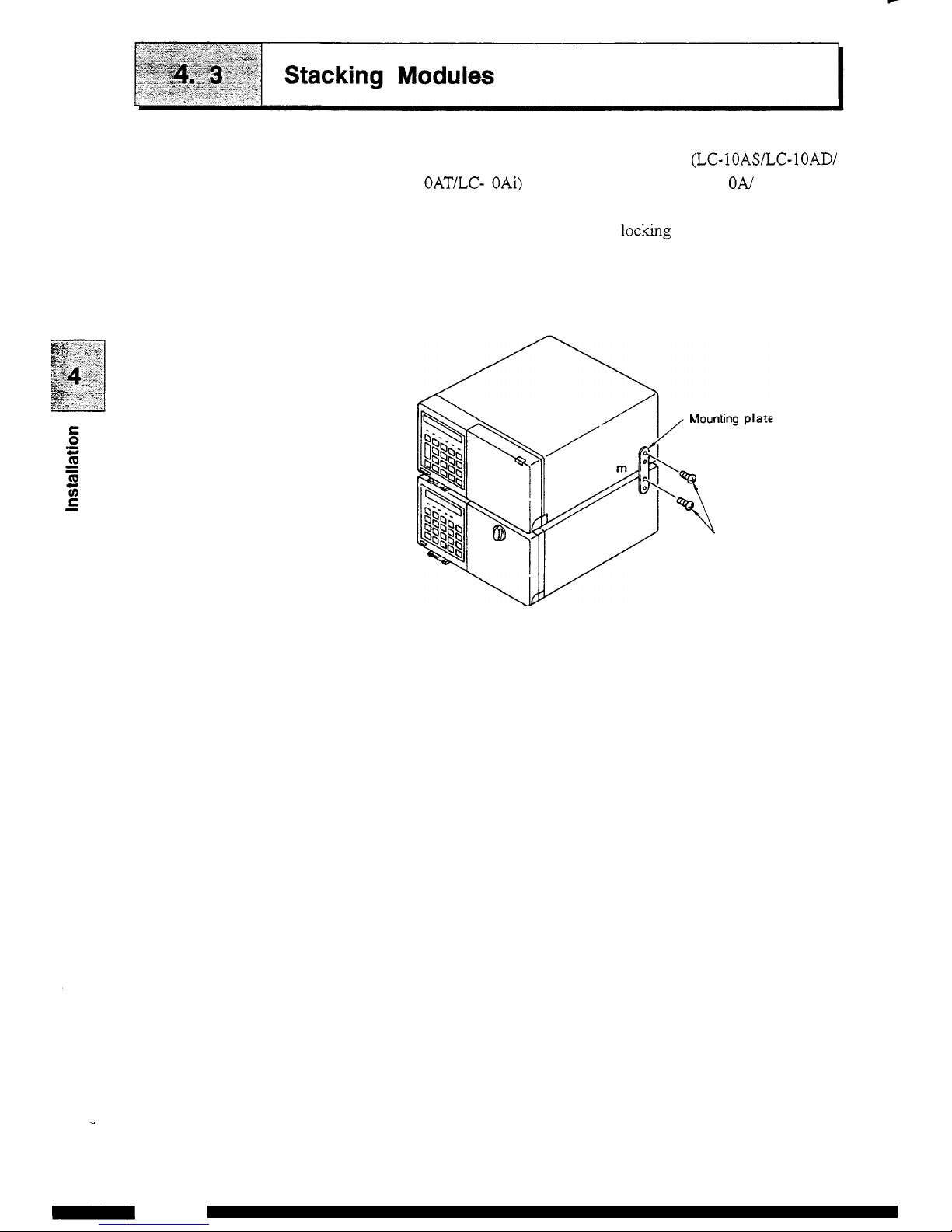
RID-1OA may
be
stacked on the pump (LC-IOASLC-lOAD/
LC- 1 OAT/LC- 1 OAi) or the column oven (CTO
-
1
ON
1 OAC). The
equipment can
be
stacked and locked for safety in case of
an
earthquake, etc. using the supplied locking plate.
(1) Refer to the figure below and remove the screws fastening
the equipment cover.
(2)
Attach the mounting plate using the removed screws.
Tighten the
mounting
plate
using the removed screws.
4-4
-
RID-1OA
Page 29
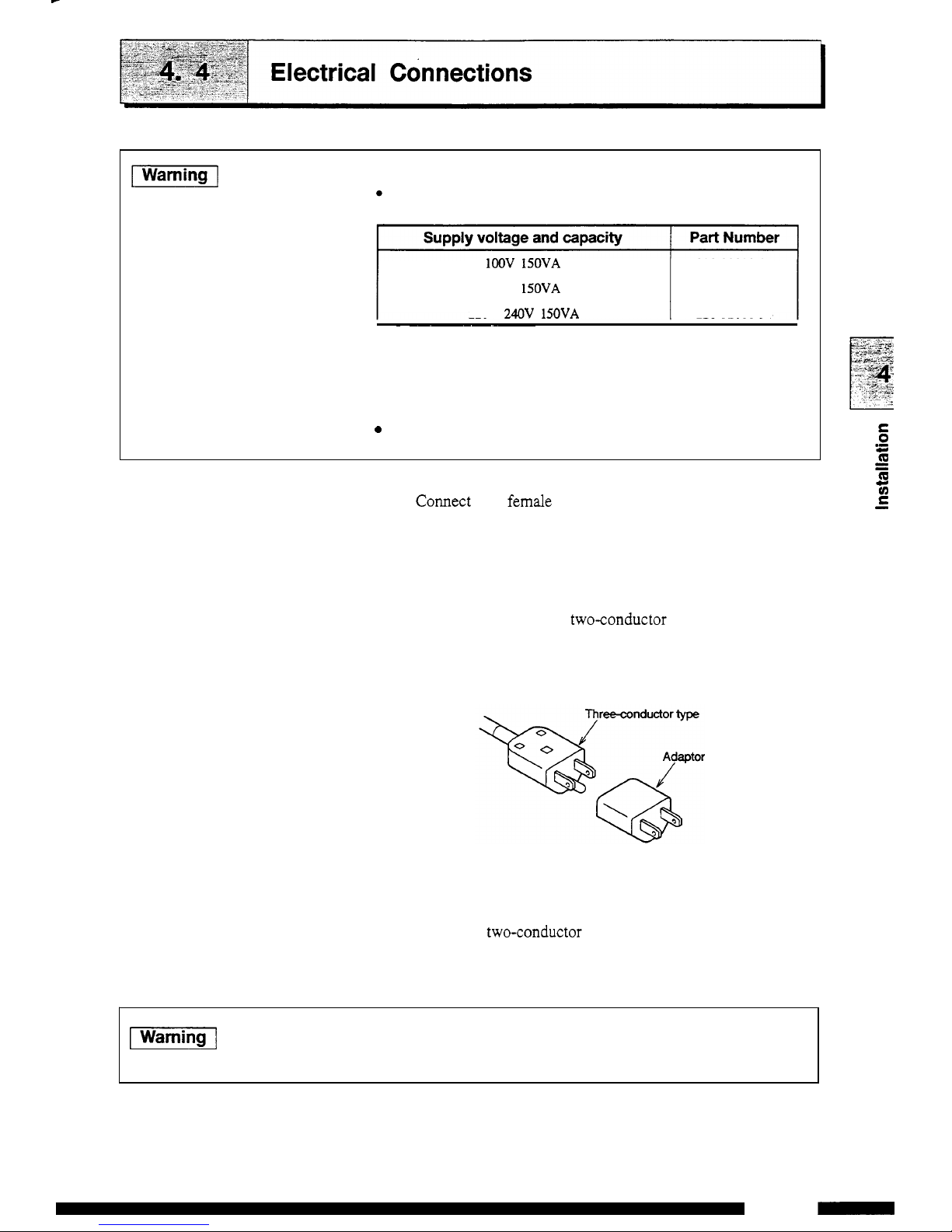
piEG@-[
Check the following points before connecting power supply.
Supply voltage and capacity
lOOV 150VA 228-32000-91
120V
150VA 228-32000-92
220
-
240V 150VA 228-32000-94
~ ~~~~~~~
When the power supply
is
not stable or the capacity insufficient,
satisfactory performance is not possible. Verify the total power
supply for the system before preparing the power supply.
0
Verify that the power switch of the main unit is
turned
OFF.
1.
Connection
to
outlet
(1)
Connect the female connector of the power supply cord
supplied with the unit to the power supply cord connector at
the rear
of
the unit, and plug the male connector into a power
supply outlet.
The supplied power cord is a three
-
conductor (3-prong) type.
When connecting to a
twoconductor (2-prong) type power
supply outlet, use the provided power supply adapter.
(2)
2.
Grounding
(1)
(2)
When the three
-
conductor type power supply outlet
is
used,
the unit is grounded by the power supply cord.
When the
two-conductor type power supply outlet is used,
the unit is not grounded.
In
this
case, ground
from
the
grounding terminal on the
rear
panel of the unit.
piiGi@l
To
prevent electric shock and to secure safe operation of the
system, always ground the unit.
4-5
RID-1OA
-
Page 30
F
-
7
umbing
Connections
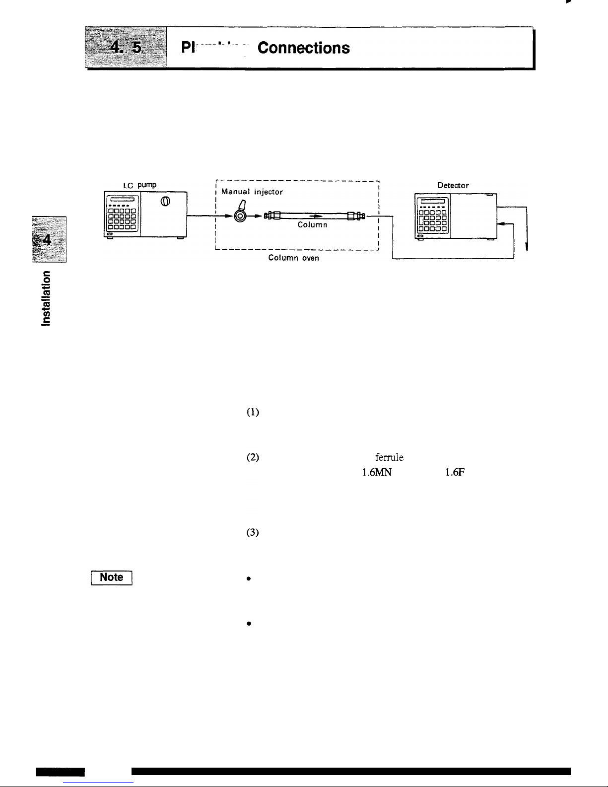
This section describes proper connection in a typical
flow
line as
shown
in the figure below:
1.
Flow
line in the system
Refer to the column oven instruction manual for installation
of
the
manual injector and column oven. When the column oven is
not
used, an injector holder and a column holder are optionally
available for installation of the manual injector and the column.
2.
Connecting the solvent delivery pump and manual injector
Connection of the solvent delivery pump and the manual injector
are described below.
Cut the
SUS
pipe
(1.6
x
0.3 supplied
as
a liquid pump
accessory) to the necessary length for the pump outlet and
injector port
2.
Install
the male nut and ferrule to both ends of the
SUS
pipe.
Attach the male nut
1.6MN
and ferrule
1.6F
(accessories of
the pump)
to
the pump outlet side, and the male nut and
ferrule (accessories of the manual injector) to the manual
injector.
Connect
an
end of the
SUS
pipe to the pump outlet and the
other end to the injector.
(Notel
Connect the
drain
tube to the manual injector ports 5 and
6.
Adjust the tip of the
drain
tube to meet the needle port of the
injector.
For all connections of the manual injector, use the male nut and
ferrule supplied
as
the manual injector accessory.
4-6
-
RID-1OA
Page 31

4.5
Plumbing
Connections
/
T
Manual
injector
Injector
holder
3.
Connecting injector and column
A typical connection
of
a manual injector and a column is
shown
below:
(1)
Cut the
SUS
pipe
(1.6
x
0.3
supplied to the pump, to the
necessary length for connecting the injector and the column.
(2)
Attach a male nut and a ferrule to the ends
of
this
pipe.
(3)
Connect the ends
of
the
SUS
pipe to the injector and the
column respectively.
Attach the ferrule and the male nut supplied with the injector to
the injector and those supplied to the pump to the column.
Make the pipe length between the injector and the column
as
short
as
possible to prevent sample band broadening.
Cut the pipe on the perpendicular and connect
it
securely to
avoid dead volume.
4-7
RID-1OA
-
Page 32

4.5
Plumbing
Connections
SUS
pipe
PEEK
pipe
Cut perpendicularly
with
a cutter knife.
Cylinder Cut perpendicularly.
&
I
\
d
\
I
Mail nut
1.6MN PEEK
Ferrule
1.6F PEEK
Mail nut
1.6MN
Ferrule
1.6F
Rear
of
manual injector
I
J
To
detector
4.
Connecting detector and column
A
typical connection between the RID-1OA and a column is
described in this section.
(1) Cut
the
supplied
SUS
tubing (50cm long) to the necessary
length for connecting the column outlet and the cell inlet
Po*.
Cut the tube on the perpendicular. When the
tube
is cut on a diagonal,
dead volume is generated which deteriorates separation.
When the flow selection block (option) is used, refer to section
5.3
Piping of
Flow
Selection Block (Option).
Connect the tubing between the column and the detector inlet with
the supplied male PEEK nut
as
shown in the next fi,we. lighten
the male PEEK nut fmly without using tools.
I
Note
I
Insert the tubing into the column joint and the male union securely
until it comes
to
the
end and then tighten the male
PEEK
nut.
Similarly, insert the cell inlet pipe until it comes to the end
and
tighten the male
PEEK
nut
so
that dead volume is minimized.
4-8
-
RID-1OA
Page 33

4.5
Plumbing
Connections
Tubing
(cut
the 50cmlong tube for use)
Manual injector
Main
body
IN
port
Male
nut
PEEK
(Tighten by
hand)
Manual injector
I
by
hand)
5.
Detector outlet side piping
(1)
Prepare a waste liquid bottle.
Connect the
drain
tube to the detector outlet. Select one
from
applied flow rate. Insert the outlet
of
the
drain
tube into the
waste liquid bottle.
the
drain
tubes listed
in
the table below depending on the
C
0
m
-
c
Max.
flow rate
Drain
tube
For extension
Remarks
[Wmin]
Fside diameter (mm) x length
(cm)]
[Inside diameter
(mm)
x
length (cm)]
3
0.3
X
100
1.ox
100
5
0.5
X
100 1.ox 100
20
0.8 X
100 1.6X
100
150
1.6X 100
1.6X
100 At mode L (option)
When using the FFX-1OA fraction collector, connect the inlet tube
of
the FRC-1OA to the detector outlet directly. Note that the
maximum
flow rate varies depending on the preparative head
of
the
FRC.
FRC
-
1OA
inlet pipe
Inside diameter
[m]
x
Length
[cm]
FRC-10A outlet pipe
Inside
diameter
[mm]
x
Length
[cm]
Max.
operating
flow
rate
[mVmin]
Fraction correction head with valve
0.8X
100
1.6X 100
20
(150')
Fraction
correction head with valve
0.3
X
100 1.6X
100
3
Fraction correction head without valve
FRC- 1OA preparative
head
0.3
X
100
*)
An
optional flow selection
block
is necessary.
The solenoid valve and flow cells may
be
damaged by application
of
back
pressure which exceeds the detector resistance pressure.
Do
not use the pipes listed
in
the table which
are
out
of
range.
I
Note
1
To
prevent the detector
from
being damaged by back pressure, it is
useful to connect the relief valve (option) to the detector outlet
when the
unit
is
used with large flow rate, or the piping
is
clogged.
4-9
RID-1OA
-
Page 34

4.5 Plumbing
Connections
Main
body
outlet
port
When piping
for
the detector inlet and outlet is completed, secure
the two piping tubes
in
the tube holder
as
shown
in the
figure
below.
I
1
I
RID-1
OA
I
Fit the tubes
in the tube holder.
/
When the front cover is
dosed.
4-10
-
RID-1OA
Page 35

1.
Connection
with
recorder
Connect the
RECORDER
terminal
of
the
RID-1OA
and the
recorder using the supplied
signal cable.
Recorde-
-t
RID-1OA
[
Tk15th terminal
of
RID-1OA
Recorder
Recorder
Recorder GND
(1
OmV
full
scale recorder)
or
the
6th
terminal
(I
mV
full
scale recorder)
The 7th terminal
of
RID-1OA
Green
~
Green
'
Grounding terminal
When using a stranded wire, twist the end tightly, or tin it with
solder.
Using
a small screwdriver or other tool, depress the rectangular
button adjacent to the appropriate terminal hole. Insert the wire and
release the button to
clamp
the wire
in
position,
as
shown
in the
flapre below.
Wire
-
Press
4-1
1
RID-1OA
-
Page 36

4.6
Connecting the Recorder and Integrator
~~
2.
Connecting
with
Chrornatopac (integrator)
Connect the Chromatopac to the
INTEGRATOR
terminals
(TBl
No. 3 and
No.
4)
in
the external inpuvoutput terminals at the rear
of
the
RID
-
1
OA.
The connection procedure is similar to that in
“1.
Connecting with
recorder.” Connect the cable supplied with the Chromatopac to the
Chromatopac side and connect each terminal
of
the signal cable to
the
terminal block supplied with the Chromatopac.
To
Chromatooac
Terminal
Mock
supplied
with
Chromatopac
supplied
with
Chromat
412
-
RID-1OA
Page 37

Each component
in
the LC-1OA series is designed
so
that solvent
leakage is discharged
from the liquid leak tube connection port
either at
the
right side
or
the lower front side
of
the equipment.
Connect the liquid leak tube if necessary.
1.
Connecting liquid
leak
tube in
LC-1OA
system
Connect the supplied L-type leak tube to the connecting port in
each component.
Connect the straight type joint to the liquid
leak
tube at the bottom
of the equipment
and
insert it into the drain bottle.
L-type leak tuhe
Liqiud leak tube
U
Connecting port
of
\
liquid leak tube Straight
type
joint
Drain
bottle
Use a T-type joint to connect liquid leak tubes for multiple
instruments.
Cut
the
supplied
drain
tube
to an appropriate len,ath.
Attach the
L-type
leak tubes horizontally or downward. Secure
them
to
the side panels
of
the equipment with the supplied lock
catches.
Position
the
waste liquid bottle lower than the bottom
of
the
equipment.
4-13
RID-1OA
-
Page 38

Chapter
5
Operation
5.1
Precautions for Operation
........................................................................
5-2
5.2
Fundamentals of Operation
.....................................................................
5-3
5.3
Plumbing
of
the
Flow
Selection Block
...................................................
5-1
3
5.5
Additional Functions
(AUX-FUNC)
.......................................................
5-21
1
CONTENTS
1
5.4
Creating and Executing Time Programs
.................................................
5
-
1
6
5
-
1
RID-1OA
-
Page 39

I
Caution
I
1.
Be sure to close the front cover during measurement.
The baseline fluctuates when the front cover is opened or
closed during high sensitivity analysis. Noise may be
increased when the front door is kept open.
2.
Precautions to prevent clogging
of
the flow cell.
Dusty
or
clogged flow cells are the most frequent causes
of
trouble in any detector. After analyzing a high concen
tration sample, thoroughly flush it from the flow cell,
using
a
large amount
of
mobile phase.
Buffer solution crystallizes upon drying, and can clog the
flow cell and tubing. Never leave buffer solution in the
unit
as
mobile phase. Always flush the flow lines prior to
shutdown
of
the instrument.
Turn
ON R flow several
times during solvent delivery and replace the reference
flow cell with water.
5-2
-
RID-1OA
Page 40

1.
Turning
power
ON
(1)
Push the power switch
on
the front panel to turn the power
ON
and
OFF.
\
d-
\
"7--
1
Power switch
OFF state
Power switch
ON
state
(2)
When the power is tumed
ON,
the
RID-10A
operates
as
follows:
Turning power
ON
All
of the dots in the display
unit
and all of the indicator
lamps light.
Control program version
No.
is displayed.
balance
wn0-I
ranae
mode
f
Rl
D-1
OA
V%.
%
1
The motor for optical balance adjustment is moved to the
set position and the instrument
seeks
the home position.
-
M(101
rsnge
mode
f'
S
EE
K
I
N
G
H
O
M
E
The position is adjusted
so
that the optical balance is at
the
optimum
position.
balance
RI(10
range
mode
(10
BALANCE
A
(3)
After turning the power
ON,
a memory check is automatically
performed and when no error is
detected
the following display
appears, indicating
that
operation is possible.
This
is the initial
State.
0
4
shift
progrun
remQte
tanpcolll
Rlbw
pol(-)
t=l~nOot=l
The
balance
and
RI
values vary depending
on
the
types
of
instrument.
E
0
-
c
E
Q)
op
5-3
RID-1OA
-
Page 41

5.2
Fundamentals
of
Operation
a
(3
@
0
a
0
2.
Display
unit
RI
(
loa)
Displays refractive index (unit
:
X
lo4
FUU)
Displays full scale of refractive index output to the recorder terminal (unit : XlOkIU)
mode Displays measurement mode.
shift Shift key indicator lamp.
prog run
remote
Time
pro,oram operation indicator lamp. Lights when time program is being executed.
Remote mode indicator lamp. Blinks when
contmlled by
SCL-
1OA.
If
[
NOT
PROTECTED
)
message is displayed and an alarm sounds
after turning the power
ON,
press
a
key. When this message is
displayed, the time program
is
initialized.
When any other error message
is
displayed,
turn
the power
OFF
and contact your Shimadzu Service Representative.
temp cont
The display unit consists of display screen and indicator lamps as
shown below.
Lights when the power is being supplied
to
the temperature controlled heater for optical
system unit.
P PP?
8
@
No.
1
Display
ordescription
I
Function
R flow
Reference flow indicator
lamp. Lights when the liquid is being supplied to the reference
flow line side.
pol
(-1
Polarity indicator lamp.
@I
balance
I
Displays position of the light on photodiode.
3.
Keyboard
The nineteen keys on the front
are
used for operation and
settings and classified into the following
three
types.
(1)
STD-func keys
Press these keys to perform a specified operation immediately
-
(
[Zero
1
key, etc.)
(2)
Shift-func keys
Press
these keys after pressing a
[
shift
1
key to perform
a
specified opeAtion
((7-1
key, etc.).
1-
5-4
-
RID-1OA
Page 42

5.2
Fundamentals
of
Operation
(3)
Edit keys
Use these keys to input parameters and edit a time program
(ten
-
key, etc.).
shift
El
I-1
I.'1
shift
[T]
0
I21
'i
Enter
(1)
STD-func
keys
Auto zero key
(-1
Zero
shift
key
[mark]
Mark key
I.1.)
Run key
(2)
shift-func
keys
(+)key
(shlft)
+
[GGF)
key
(shlftj
+
[R]
key
Press this key to perform zero adjustment. Returns the baseline to
the zero position
set
by
[-)
.
Press
this
key to move the zero position on the recorder. It is
moved upward by pressing
A
side and downward by pressing
V
side.
Press this key to add Mark to the data being recorded in the recorder
by pressing this key. Mark is not valid in the integrator output.
This key is a switch to
start
and stop a time program.
These keys move
to
time program creation mode.
These keys drive the zero glass and adjust its position to'optimal.
These keys switch the solenoid valve to replace the liquid inside
the reference cell with the mobile phase.
@
+=
key
These keys switch the polarity of recorder output.
[pol
(-1
1
LED
is lit for
(-)
polarity.
E
0
.-
c
f
op
5-5
RID-1OA
-
Page 43

5.2 Fundamentals
of
Operation
=+
(mode]
key
(shlftJ+
@
key
(3)
edit
keys
-
19)
Numerical keys
CEnfer)
Enter key
@
Clear key
a3
0"
(shlft+m
Delete key
uu
Function key
m+m
Back key
-
-
4.
Basic
operation
These keys select the measurement mode.
The measurement mode changes
from
A
+ P +
L
3
A.
A
:
Analytical mode
P
:
Preparativemode
L
:
Large-scale preparative mode
For
the operation
of
each mode, refer to section
5.3.2,
Changing the
Measurement Mode.
These keys can be used to set time constant.
Values from
1
to
10
can be set. For the relation between each value
and time constant, refer to section
5.2.9,
Setting the Response.
Input numerical values.
Sets input values.
Returns the display screen to the initial state.
Press
this key to clear an input value when entering a numerical
value. Press this key to clear the display and alarms when an
error
is
displayed. Equipment failure errors cannot be cleared with this key.
Deletes a line in the time program.
Advances to
the
next item in
the
display screen.
AUX.
FUNC
setting screen
is
forwarded.
Returns to the previous item.
AUX.
FUNC
setting screen
is
scrolled backward.
Before starting analysis, flush the detector flow line with mobile
phase. Supply the mobile phase at a flow rate of
1
mUmin, and
then press
(shlftl
and
B.
The solenoid valve is switched and
the
(R)
lamp is lit. Solvent flows
through
the sample and the
reference sides
of
the
detector cell replacing solvent
in
each. Supply
solvent for approximately
20
minutes with Wow ON. Then,
turn
Rflow ON/OFF several times to drive the bubbles out of the cell.
Retum to Mow
OFF
state, and wait
until
the baseline stabilizes.
When the balance value is
more
than
50,
press
and
[F)
to perform optical balance adjustment.
When the baseline
is
stabilized,
start
analysis.
5-6
-
RID-1OA
Page 44

5.2
Fundamentals
of
Operation
I
Note
I
When the liquid inside the flow lines is not sufficiently replaced
with the mobile phase, the baseline takes longer to become stabilized
and the
drift
becomes large.
To
perform effective replacement, turn
R
flow
ON/OFF
several times at an interval of
two
minutes.
Switching flow lines during solvent delivery at large flow rate
in mode
L
may damage the solenoid valve and the flow cell.
Thus, the following message appears when performing
R
flow
in mode
L.
f
CHECK
FLOW
7
Press
[E)
after the flow rate is changed to 1 mumin.
To
avoid trouble caused by bubbles, refer to the following.
When the pump sucks bubbles, degas the solvent with the
ultrasonic cleaner. If dirt on
the suction filter is the cause,
clean the filter with the ultrasonic cleaner or replace it.
Bubbles may not be easily removed when using
an
aqueous
solvent. Flush the flow lines with methanol
or
acetone.
When replacing the aqueous solvent with organic solvent or
vice versa, bubbles may be generated successively. If
bubbles can be observed, flush the flow lines with thoroughly
degassed solvent.
5.
Setting the measurement mode
(Example)
When changing the measurement mode from
A
to
P
Press
[shift)
and
.
The mode is changed to P to perform optical balance
adjustment.
balance
RI
(lo)
range
mode
100
BALANCE
P
0
0
4
P
5-7
RID-1OA
-
Page 45

5.2
Fundamentals
of
Operation
I
Note
I
I
Note
I
When the above operation is repeated, the mode is changed form
LA-+P+LJ
.
Mode L is only applicable when an optional
flow selection block is installed. When
the
block is
not
installed, do
not perform measurement in mode
L.
Refer
to
5.3.1 for the mode setting when using the flow selection
block.
Mode
I
Refractive
index
measurement range
I
Input step
0.01
step
for
0.01
to
1
1
step
for 1 to
500
1 A 1
0.Ol-500X1O4RIU
I
P-L
~1-smx1o"RIu
I
1
step
for
I
to 5000
Select the mode corresponding to the refractive index
of
the
sample
to
be
measured. When the index is
500
x
10"
FUU
or less, use
mode A.
Note that the setting of mode
P
has wider measurement range while
it
has
the larger baseline noise.
The range value will
default to 100 when
the
mode
is
changed
as
described below.
0
When
the
mode
is
switched
to
mode P or L during measurement
with the range
of
0.01
to
1
.OO
in mode
A.
0
When the mode is switched to mode A during measurement
with the range of 501
to
5000
in mode
P
or
L.
6.
Setting measuring range
The procedure to set the recorder range is
as
follows:
Changing the range
from 4 to
16 X lo4
FUUFS
(1)
Press
[f..c)
once in the initial state to access the range
parameter (blinking).
balance
wr10-7
Rnpe
mode
(2)
Input
0,
@and
(E.t.f)
ba)uue
warn
rangs
mode
0
0
16
A
(3)
After a value is input, it
returns
to the initial
state.
5-8
-
RID-1OA
Page 46

5.2 Fundamentals
of
Operation
7.
Changing
the
range
(1)
When a recorder
is
connected
to
the
RECORDER
terminal,
set the range at a value about
1.2
times as much
as
the
expected maximum peak value. Maximum peak will be
about
80%
of the full scale ensuring that peaks remain
on
-
scale.
(2)
When a Chromatopac (integrator)
is
connected
to
the
RECORDER terminal
(lOmV terminal),
peaks
having
refractive index up to about
100
times as much
as
the setting
range can be recorded. Set the measurement range at
a
value
about
1/80
of the expected maximum peak refractive index.
Normally, the recorder range
is
set
at
a value
of
about from
1
to 10 and the plot full scale is adjusted by changing
AmN
on
the
Chromatopac side. The relationship
of
the
setting
range and attenuation of Chromatopac
(ATTEN)
for the plot
full
scale
when connected to the RECORDER terminal
(10mV) is
as
follows:
Plot
full
scale
Plot full
scale
=
Setting range
x
2-/10
[
x
IO?RUFS]
5-9
RID-1OA
-
Page 47

5.2
Fundamentals
of
Operation
AUX RANGE
value
1
2
(Exam
p I e)
When that range
=
1,
ATTEN
=
2
:
Plot full scale
=
1
x
22/10
=
0.4
[
x
lO-kUFS]
(3)
When a Chromatopac is used as a recorder, connect it to the
INTEGRATOR terminal and set the range at
A?TEN on the
Chromatopac side.
It
is
also
necessary to make a rough range
setting on the detector side since the dynamic range
of
the
detector is extremely wide. This setting
is
made by setting a
value in
the
parameter AUX RANGE. Relation between
AUX RANGE value and
INTEGRATOR
terminal output
are
listed in the table below:
INTEGRATOR
terminal output
Remarks
1
x
~O~RIUN
1
x
103
RIUN
Compatible
with
AUX-L
of
RID-6A
~
4
I
~
Compatible
with
AUX-H
of
RD6A
2.5
X
lo4
RIUN
Plot full scale for Chromatopac determined by AUX RANGE value
and
AmN value is
as
follows
:
Plot full scale refractive index
(X
lo4
RIUIFS)
determined
by
AUX RANGE value and AlTEN value.
I
I
AUXRANGE
I
O
I
Oel
I
1
I
10
1
0.25
I
I
1
I
0.21
21
20
I
0.5
I
(Example)
When
AUX
RANGE = 2 and Chromatopac AmN
=
7,
the plot
scale becomes
128~ 1 O%U.
5-10
-
RID-1OA
Page 48

5.2
Fundamentals
of
Operation
8.
Zero adjustment
of
recorder
Before starting analysis, adjust the zero position of the recorder
as
follows:
(1)
Set the measuring range to 0 to short-circuit the recorder
output. SHORT is displayed in the range display. (Refer
to
section
5.2.6,
Setting the Range.)
Adjust the pen position to
0
scale on the chart paper using
the pen position recorder adjusting knob.
(2)
(3)
(4)
Reset the measuring range at a value required for the analysis.
F’ress- ,and the
pen
returns to almost 0 scale on the chart
paper.
(5)
Press
(zeroshiftAV1
to move the baseline to a desired
position and
start
analysis.
(6)
Press the
key to return the baseline to the previous
position.
9.
Setting the
RESPONSE
In
this
equipment, a digital noise filter is used to improve
SIN
ratio.
Response improves when setting the filter response low, but the
noise reduction effect becomes small.
On
the contrary, response is
worsened when setting the response high, but the noise reduction
effect becomes large. Ten digital filter response steps are available
when setting the parameter to
RESPONSE.
RESPONSE
values and
corresponding time constants for analog filters are
as
shown in the
table below:
c
0
-
c
f
00
5-1
1
RID-1OA
-
Page 49

5.2
Fundamentals
of
Operation
value
1
E
0
Q
.
-
+.I
5
op
(
Letters in brackets are response
ofRID6A.
)
at half-height
0.05
sec
0.2
sec
RESPONSE
I
Corresponding time constant of analog
CR
filter
I
Minimum peak width
I
2
3
4
5
6
7
0.1
sec
0.4
sec
0.5
xc
(
F
A
S
T
)
2.2
sec
1.0
sec
4.8
sec
1.5
sec
(STD)
7.2
sec
3.0
sec
(SLOW)
13
sec
6.0
sec
26
sec
9
10
18
I
8.0
sec
I
36
sec
I
10.0
sec
45
sec
2.0
sec
9
sec
1
\\ I //
// I \\
5
[
RESPONSE
@
O
Input a value using numeral keys and press
(Enter).
Press
@
to return to the initial display.
(Note)
As
response is increased,
data
processor response
decreases, peak height decreases, and width at half
-
height
increases. It is recommended that response
be
set at a
value such that, for a given half
-
height width, the peak
height drops no more than
10%.
The relation between
response time,
peak
half-height width, and peak height
reduction is shown in the figure below.
To select a response using the figure, determine the width
at half
-
height of the narrowest peak of interest. Using the
graph,
find the point of intersection between that width
value and the
90%
height value. Set the response which
corresponds to a value
I
the time constant
as
read
from
the graph. Note that response has no effect on peak
area.
Peak
area
does not change even when a low response
value broadens the peak.
100%
-
I
0)
al
r
05
SCC
Y
([I
al
1.0
Scc
a
3.0
fo~
6.0
scc
_-
0
10
10
Peak
width
at half-height
5-12
-
RID-1OA
Page 50

1.
Usage
of
each mode
Refractive index measuring range
(xlobRIU)
Measurement mode
When the RID-1OA is equipped with the flow selection block
(option), measurement mode can be selected for high sensitivity
analysis, preparative and large
-
scale preparative mode. Operation
in
the large scale preparative mode requires the optional block.
Flow
rate range Tubing
(mUmin) connection
Mounting of the flow selection block is performed by a service
engineer. Refer to section
12.3.
Analytical
(A)
Preparative
(P)
Large-scale preparative
(L)
Preparative
-
500
20
Fig.
1
-
5000
20
Fig.
1
-
5000
150
Fig.2
Large-scale
preparative
Mode Setting Application
Analytical A For general analysis. The flow
lines
are
the same
as
that
of
the
RID-10A without
the
flow selection
block. This mode is compatible
with the
FUD-6A.
P
For measuring samples of high
concentration. Samples ten times
S
as
concentrated
as
those for mode
0
-
c
A can
be
measured.
f
L
For measuring samples of high
op
concentration at large flow rate.
Samples
of
the same concentration
as
those of the mode P can be
delivered
at
150
mUmin.
2.
Changing the measurement mode
(1) Selection of mode setting
The
current mode is displayed on the
LED
display. Switch
the
measurement mode by pressing
and
@
.
1
A
:
Analytical mode
L
P
:
Preparative mode
1
L
:
Large-scale preparative mode
Mode setting must be accompanied with corresponding
tubing connection
as
shown in Figs.1 and
2.
5-13
RID-1OA
-
Page 51

5.3
Plumbing
of
the
Flow
Selection
Block
~
Max
flow
rate
(mumin)
50
1.50
E
0
I
c.
f
8
~~~~ ~ ~ ~~ ~~
Drain tubing
For
extension
0.
D.
x
1.
D.
x
Length [rnm]
0.
D.
x
1.
D. x Length [mm]
1.6X0.8X lo00
3.2X 1.6x lo00
3.2 X 1.6 X lo00
3.2 x 1.6
X
lo00
Drain
tube
Use the following types
of
drain
tube for large-scale preparative
Max
flow
rate
(mumin)
50
mode. The longer and/or smaller
I.D.
tubing than the specified
one causes
high
back
pressure beyond the value
in
the specifications
of the detector, which may lead to damage of the detector.
FRClOA
inlet tubing
0.
D.
x
1.
D.
x
Length [mrn]
1.6 X 0.8
x
lo00
(FRC-
1OA
accessory)
FRClOA
outlet tubing
0.
D.
x
1.
D. x Length [rnrn]
3.2
X
1.6
X
lo00
(FRC-
1
OA
accessory)
3.2
X
1.6 X lo00
[Note)
When a fraction collector
FRC-1OA
is
used,
use the following tubing.
I
I
150
I
3.2X 1.6X lo00
I
(FRC- 1
OA
accessory)
When using a fraction collector made by other manufacturer, check
that the back pressure caused by connecting
the
fraction collector
does not exceed the limit that the detector can resist. Pay attention
to pressure change,
as
well
as
back pressure when switching the
preparative valve.
(2)
Changing the tubing connection
Open the front panel and change the piping connection
because large
-
scale preparative mode has different plumbing.
+column
1
Drain
Fig. 1 Tubing connection
in
the
analytical and
preparative
modes.
5-14
-
RID-1OA
Page 52

5.3
Plumbing
of
the
Flow
Selection
Block
f-
Column
Fig.
2
Do
not
tubing
Tubing connection in the largescale preparative mode
set the instrument to mode L with analytical
and
preparative
connection. Similarly, do not set the instrument to mode
A
t
0
or
P
in
large-scale preparative tubing connection.
-
c
0"
5-15
RID-1OA
-
Page 53

t
0
-
c
E
a
OQ
Command
ZERO
MARK
RNGA
1.
Command
list
Commands which can be used for a time progam
are
listed below.
Description Setting range Remarks
Execution of zero adjustment
Marking on output for recorder
Designation
of
output range for recorder (mode A)
Not applicable
Not applicable
0,O.Ol-
500
Unit: x106RIUFS,
RNGP
RESP
Designation
of
output range for recorder (mode
P)
Designation
of
output range for recorder (mode
L)
Designation
of
response
0,
1
-
5000
Recorder is short-circuited when
set to
0.
Refer
to
section
5.2.
Fundamentals
of Operation.
1
-
10
1
EVNT
1
EVEhToutputON/OFF
0,
1,2,
12
Refer
to
section
5.5,
Additional
Functions
.
1
POL
1
~olaritysetting
STOP
I
O’I
Ends a program. Not applicable
Positive polarity
Negative polarity
RNGA
(setting value)
1.40
150
I
LOOP
I
Repeats all preceding steps in
the
pro,.ram.
10-25255
I
Value
0
repeats
a program
256
times.
RNGE
(execution value)
1-00
2.00
[Notel
Setting the RNGA at decimal number
RNGA enables increments
of
0.01
unit steps. However, when set
at
a
range more
than
1.00,
fraction
of
5
and over is counted
as
unit
and
the
rest is omitted.
(Example)
I
Note
I
Execution of RNGA and RNGP
RNGP setting during
a
time promoram is ignored in mode
A.
RNGA setting during a time program is ignored in mode P or
L.
5-16
-
RID-1OA
Page 54

5.4
Creating and Executing Time Programs
2.
Explanation
of
display
screen
The edit mode is used to create a time program.
(1)
Press and
@.
A
screen similar
to
the one below
will
be
displayed.
b
Q
0
Number
of
steps already set
0
Number
of
remaining steps
The above example
shows
that the time program is
set
for
10
steps and there are
22
remaining steps.
(2)
PressLEnter 1 to display the following:
I
I
I
6
@
@
Commandname
0
Setvalue
Elapsed time fiom time program
start
(minute)
(3)
Press
[Enfet)
again, to display the following:
The contents in the display are
the
same
as
those
in
(2)
balance
RI(t0
range
mode
\\I//
f
1.00
ZERO
1
The above display shows that
AUTO
ZERO
is.activated
one minute
after
start
of the time program.
E
0
-
c.
E
Q)
8
5-17
RID-1OA
-
Page 55

5.4
Creating and Executing Time Programs
3.
Flow
of
setting
Flow
in
setting a time program is shown below
:
0
4
A\j
Press lshlftjandm.
I
(CE)
baknce
RI
(104)
ranga
mode
0
USED
32
LEFT
Press
CEnter).
RI
(lo4)
range
mode
\\I I I I
//
//I
I
I I
\\
TIME
FUNC
VALUE
I
J
\\I
I
I
I
//’
//I I I
I
\\
0. 00
ZERO
Input time with numerical keys and then press [Enter).
balance
(lo4)
range
mode
10.
00
ZERO
--@
\\I
I
I I
//
//I I I I
\\
Each time
Ifunc>
is
pressed, commands are
displayed sequentially. Press
IEnter)
when the
objective command is displayed to set the command.
batance
(lo4)
range
mode
1
0.
0
0
RANGA
/ylAL,UIE
\\I I I I I
I//
When a command except
for
ZERO,
MARK,
and
STOP
is selected, input a set value for the command
with
numerical keys
and
then press
(Enter).
I
Next setting
If
no program
is
input (even
a step):
Operation
of
Is1.ft1
and
[fun,,,)
in
this
state returns the display to
the previous setting.
5-18
-
RID-1OA
Page 56

5.4
Creating and Executing Time Programs
4.
Deleting
a
step
(Example)
5.
Start
and stop
It is unnecessary to set the time order
of
steps as they are
automatically rearranged.
Set a
STOP
command at the end
of
a
program unless the
program is to
be
operated continuously.
0
When selecting a function, the previous function is displayed
by
-
-
pressing and
w.
Display the step to
be
deleted and press
@
and
@
.
Deleting the fmt step
in
the program set in the previous section.
(1)
Display the step
to
be
deleted.
(2)
Press
lshlftl
and
.
120.
00
RANGA
21
The
first
step in the program
is
deleted and the second step is
displayed. When the second step
is
not set, the following is
displayed:
-
m(lo3
law
mode
0
USED
32
LEFT
After setting a time program,
start
and stop the program according
to the following:
(1)
Press
(Nnj
.
The LED for
I
prog
run
1
is lit, and the time
program
starts.
There
are
two
methods
to
stop a time program: forced stop
of a time program in
process, and stop of a time program
using the
STOP
command in the program.
To
stop the time
program forcibly, Press again. The LED for
[El
is
dimmed,
and the program stops.
(2)
5-19
RID-1OA
-
Page 57

5.4
Creating and Executing
Time
Programs
6.
LOOP
command
A
program can be repeated any number of times using a LOOP
command.
E
0
-
c
f
OP
TIME
mc
VALUE
15.00
ZERO
20.00
MARK
30.00
LOOP
3
According to the above setting, steps
(1)
and
(2)
are repeated
3
times at
an
interval of
30
minutes.
When parameter is changed while executing a time program, the
changed value
is
valid only until the end
of
the program. On
completion of the time program, the parameter is reset to the
value set before executing the time program.
Any
number up to
255
can
be
set
to the
VALUE
for the LOOP
command. When
0
is
set for the value, LOOP
is
repeated
256
times.
The
program
that
was
set
after
the
LOOP
command is not executed.
The program stops at the end of the LOOP command.
5-20
-
RID-1OA
Page 58

Add
i
ti
ona
I Functions
(A
UX-
FU
N C)
Type
4
4
The following Additional Functions are equipped with the
RID
-
1
OA.
Command Function
TOTAL EN
CELL
Indicates the total quantity of light irradiated on the photodiode.
Displays the quantity of light irradiated on
each of the right and the
left
side of
photodiode.
1
1
1
I
1
I
CELLTEMP
I
Sets the cell temperature.
I
AUX
RANGE
EVENT
EXT-S
Sets output range to
in
integrator.
Controls output relays on
the back of the
FUD-IOA.
Sets
control mode for the control of external equipment
through
the EVENT
I
4
I
ACTTEMP
I
Displays the actual temperature of the optical unit.
I
1
4
3
output relays.
Monitors when running a time program.
Displays the lamp lit time.
Locks
the keypad, preventing unwanted entries.
MONITTIME
LAMPTIME
CLOSE
KEY
1
1
1
~-
-
~
--~___~-~
1
Sets address of the
RID
1OA
for control via system controller.
SPAN
A
SPAN P
SPAN
L
Inputs the span value of the analysis mode.
Inputs the span value
of
the preparative mode
Inputs the span value
of
large-scale preparative mode
(An
optional
flow
selection block is necessary.)
I1
ImAL
I
Selects independent operation or control via system controller.
I
I
1
1
LAMPVOLT
I
setting of the lamp voltage
I
“Type”
in
the above table indicates a kind of operating procedure.
Type
1
:
Input a value using numerical key
and
then press[=] key.
Type
3
:
Press
[Enfer)
key to execute the function.
Type
4
:
The status
is
displayed.
2.
Setting procedures for AUX.
FUNC
TOTAL
EN
(Total
lamp energy)
CELL
(Lamp energy of each photodiode.)
[
TOTAL
EN
7000
Displays the total quantity of light irradiated into the photodiodes.
(unit
:
mV)
CELL
3550
3450
I
E
0
-
c
f
8
Displays the quantity
of
light irradiated into each of the right and
left photodiode. (unit
:
mV)
5-21
I
RID-1OA
-
Page 59

5.5
Additional Functions
2
IX~O-~
RIU
N
Compatible
with
AUX-L
of
RIDdA
3
1
x
RIUN
4
25x10a
RIUN
Compatible
with
AUX-H
of
RlD-6A
t
CELL
TEMP
(Cell temperature setting)
ACT TEMP
(Monitors actual cell temperature)
AUX RANGE
(Integrator output
full
scale)
EVENT
(Event output terminals)
balance
wriol
lam
mode
(CELL
TEM
P
40.0
Sets the cell temperature at the measuring
unit.
When the
flow
rate is larger than
3
dmin,
turn
this
OFF.
When the
flow
rate is less than
3
mL/min,
set the temperature to
the room temperature
+
12
“c
balpma
m(103
range
mode
(ACT TEMP
40.0
I
Displays the actual cell temperature
in
the optical unit.
[
AUX
RANGE
-
7
I
1
I
1x10~
RIUN
I
I
[
EVENT
This
function
sets
the relays
accessed
by the
EVENT
output terminals
on
the back
of
the
FUD-1OA.
OFF
is
an open relay and
ON
is
closed.
Input the desired value and press
(GI.
Setvalue
I
EVENT1
I
EVENT2
I
5-22
-
RID-1OA
Page 60

5.5
Additional Functions
Set
value
0
1
EXT-S
(External
starts,
sets specific
Control
mode
Relay contact points
are
controlled by the
EVENT
set
value.
Relay
1
(EVENT
1
terminals) closes
at
the
start
of
a time
pro-
gram.
Useful
starting
data
processors or
zeroing detectors.
bamca
RI(10-7
range
mode
EXT-S
-
2
3
functions for the
EVENT
output
terminals)
This
feature is typically used to control external equipment
through
the
EVENT
output (relay 1 and
2).
Input the desired value, then press
(GI.
Relay
2
(EVENT
2
terminals) closes on detection
of
the error
of
the
RIDlOA.
Useful
for
communicating
to
external equipment
Both functions described above
are
enabled.
MONIT-TIME
(Monitors program elapsed time)
LAMP
TIME
(Monitors the lamp
lit
time)
r
0
Q
d)
-
c
L
When
running
a time program, the time elapsed
from
the
start
of
8
the program is displayed.
Input the desired value, and press
(K]
.
Sets
display
of
elapsed
time.
When setting this function, the time program display during
operation
is
as
follows:
-
W(f0)
ranee
mode
,
.
\
Elapsed
time
from
the
start
of
the
program.
-
R(103
rage
mode
LAMP
TIME
150
Displays the integration time of the lamp lighting. (unit : hour)
The
life
of
a lamp
is
20,000
hours.
When the lamp life
is
close to the
end, contact your
Shimadzu Service Representative.
I
5-23
RID-1OA
-
i
Page 61

5.5
Additional Functions
Set
value
0
CLOSE
KEY
(Prohibition of key input)
Function
Allows
control
via
an
SCL
-
10A.
ADRS
(Remote address)
1
C
0
0
LOCAL
I
c,
Independent
operation
(local
mode).
L;
Q)
(Setting of the local mode)
op
LAMP VOLT
(Lamp voltage)
SPAN
A
(Span factor in mode
A)
SPAN
P
(Span factor in mode
P)
balance
RI(10)
range
mode
CLOSE
KEY
This function locks keypad, preventing entry, and is invoked by
pressing
(=]when the above display is shown.
To
restore
-
-
keypad function, press
and
a
simultaneously.
balmce
RI(10)
range
mode
ADRS
3
Sets a remote address setting (port
No.)
when
this
equipment is
connected to the system controller
(SCL-IOA)
for use. Input the
address number, then press(
Enter
.
For port
No.,
see
section
7.1,
Connection with System Controller
SCL
-
1
OA.
[
LOCAL
Selects independent control or control via an
SCL-1OA
system
controller.
A
set value 1 allows the
RID-1OA
to
be
controlled from
its
own
keypad even when connected to an
SCL
-
1
OA.
Input the desired value, and then press
[GI.
Sets a lamp voltage. (Input range
:
0
to
5.00)
Normally, input the value such that value of
TOTAL
EN
is
within
the range from
6,000
to
9,OOO.
balsra,
RI(10-7
range
mode
(SPAN
A
1.
00
1
Inputs the span value of the analytical mode.
balsra,
W(10-7
me
mode
(SPAN P
1.
00
I
Inputs
the span value of the preparative mode.
5
-
24
-
RID-1OA
Page 62

5.5
Additional
Functions
SPAN
L
(Span factor
in
mode
L)
baiance
FII(I~
range
mode
SPAN
L
1.
00
Inputs
the
span value
of
large-scale preparative mode.
Large
-
scale preparative mode is applicable when the
flow
selection
block option
is
installed.
I
5-25
1
RID-1OA
-
Page 63

c
Chapter
6
Initial
Performance
Test
-1
6.1
System
Performance
Check
....................................................................
6-2
6
-
1
RID-1OA
-
Page 64

This
chapter contains
an
explanation
of
the operation check for the
simple system
in
the
figure
below.
Detector
(RID-1OA)
Column oven (CTO-1OA)
Manual injector
(7725)
Pump (LC-IOAD)
Reservoir
box
rchromatopac
(C-RGA)
D
9
sser
(DGU-1OB
I
Option
box
S
L370d
-Approx.
540
DGU-1OB
LC-1
OAD
CTO-1
OA
RID-1OA C-R6A
Helium gas
L---L
__--
J
Manual Column
injector
Reservoir
1.
Preparation
2.
Connection
3.
Operation
Prepare
required
reservoirs.
Prepare mobile phase. (Refer to section
4.)
Connect the input cable of the Chromatopac to the
INTEGRATOR
output terminal
of
this
equipment
using
the
signal cable supplied
to
this
equipment through the terminal
block supplied to the Chromatopac.
Turn
ON
the system power.
Open
the
drain
valve of the pump
and
purge the entire flow
line to prime the pump. Suck out about
4OmL
using the
syringe.
Close the
drain
valve and operate the pump at 1 mWmin.
Verify
that pump pressure
is
stable
and
mobile phase
is
flowing
from
the outlet.
Set
the temperature of
CTO-1OA
to
4Q°C.
Set parameter
AUX
RANGE
of
RID-1OA
to
2.
(AUX
output
range
becomes
1
x
~O-~RIUN.)
Set the Chromatopac
AmN
to
4.
(Plot full scale
of
the
Chromatopac becomes equivalent to
16
x
lo-.)
6-2
-
RID-1OA
Page 65

6.1
System Performance Check
(8)
Press
[ZERO
I,
Is) , lo)
and
[
Enter
1
on the Chromatopac to
center
the
Den Position.
(9)
Press mid
on
the ChromatoDac to dot the
output.
(10) Wait
till
the
baseline becomes stable.
Good
example
0
Stable
Bad
examples
x-
There are
spi kings.
Increases
with
the
X
.-H
lapse of
time.
'-\
Decreases with the
lapse
of time.
'X
Unstable
(11) Set
AmN
to 8 on the Chromatopac. (Chromatopac full
scale becomes equivalent to about
256
x
10-6RIU)
(12)
Press
(5)
,
,
-
and (=)on
the
Chromatopac.
plotting.
(14) Inject sample to the injector.
(15)
Press [=]of the Chromatopac simultaneously with the
sample injection.
4.
Example
of
analysis
result
An example
of
analysis under the following conditions
is
shown
below.
Mobile phase
:
AcetonitrilelWater
=
75/25
Column
:
Asahipak
NH2P-50
4.6mm
0
x
25cm
Flow rate
:
1
mwmin
Column temp
:
40°C.
Sample
:
Fructose
in
loomL
water,
lo&
Grucose 100 mg injection
Sucrose 100 mg
Maltose
100 mg
Raffmose
100 mg
RID-1OA
-
Page 66

6.1
System
Performance
Check
(Example
of
chromatogram)
C
Fructose’i.
379
Grucosel9.349
SucroseiIZ.
664
f
’hia
t
tose/’lj.
324
**
CALCULATION
REPORT
**
CH
PKNO
TIME
AREA
1
-
7.379
s40909
s
9.349 551971
9
11.661
862498
10
15.324
533931
12
22.591
761268
TOTAL
-
3553579
--------
HEIGHT
33027
27933
30889
14479
12786
139055
---
!.IF
IDNO
COSC
XAYE
1
..
Fructose
?’
-
Grucose
3
Sucrose
v
4
31a I t
ose
J
Raf
f
i
nose
7
-
---------_
0
6-4
-
RID-1OA
Page 67

Chapter
7
Control
from
the
External Equipment
7.1 Connection
with
System Controller
SCL-1OA
.......................................
7-2
7.3 Connecting External
Input
and
Output
Terminals
......................................
7-10
7.2 Control
from
the
SCL-IOA
....................................................................
7-3
I
7
-
1
~
RID-1OA
-
Page 68

c
t
P
3
U
w
i!
-
1.
Preparation
(1)
Using the supplied optical cable, connect the
REMOTE
connector at the rear panel
of
the RID-1OA and the
REMOTE
connector
of
the
SCL
-
1
OA
r(
RlPlOA
(SIL)
(FRC)
REMOTE
1-17
1-21
1-37
1-47
r5-1
r61
r?l
r87
4
Do
not bend the
remote
control optical cable at less
than
a
120"
I
angle.
(2)
Set a value
for
ADRS
in
AUX.
FUNC.
Input the
port
No.
of
the
SCL-IOA
to
which
the optical cable is connected to the
parameter
ADRS
of
this equipment.
7-2
-
RID-1OA
Page 69

Refer to the SCL-1OA System Controller Instruction Manual for
basic operation of the system controller.
1.
Power
ON
and
CONFIG
screen
Turn
ON
the SCL power switch to display the CONFIG screen.
When the detectors and the
SCL
are properly connected,
(LINKED1
is displayed at the right side of both
[=I
and (when
two
detectors
are
connected).
Equipment connection for controlling the detectors by SCL
is
defined on
this
screen. Highlighting the name of the unit defines
it
as
being present and the system controller will
perform
a link check
upon power up. Unit definitions are displayed only once after the
initial installation. These definitions are stored in the SCL and are
required
only
once unless the system configuration is changed.
Module name
-
SYSTEM
CONFIGURATION
L
INKED
L INKED
L INKED
L
INKED
FRC L INKED
~
SUBC
L INKED
.-.
pr.88
MENU
PUMP.
B
LINKED
LOCAL
DET.
B
LINKED LOCAL
LINKED LOCAL
,
Function line
Define
the
detector connection according to the following procedure
:
(1) Display line a in the function line
as
in the following
figure. When b is displayed in the function line, press
[G)
once to change the display.
a
CI
I
(2)
Select the detector connected to the function key and the
equipment name is highlighted on the screen.
Equipment of display
does
not accept control by
SCL
even when its name is highlighted. Refer to section
5.5,
Additional
Functions to change the local mode to the remote mode.
RID-1OA
-
Page 70

7.2
Control
from
the SCL-1OA
2.
Main menu screen
Press
(menu)
in
the
CONFTG
screen to display the main menu
screen. Press to access the
main
menu from any screen
.
MENU
ANALYSIS FILE PARAMETERS
:o
TIME PROGRAM
:I
PUMP CONTROL
:2
DET CONTROL
:3
FRACTION COLLECTOR
:4
AUTO !NJECTOR/ANAL SEQUENCE:S
MON I TOR
:6
SYSTEM
:7
tus
9999.9
0
/o
0
READY
3.
Setting initial parameters
Press numeric key 0 in the main menu screen or move the cursor
to
the number 0 and press
[s)
to display the parameter screen for
analysis file.
This screen
also
displays parameters for equipment other than
detectors. These parameters can be reset.
I
I
ANALYTICAL PARAMETERS
FILE
0
-------PUMP-------
- -
- - - -
-
DET.
A
(
ISO.
)
RANGE
100.
00
A. FLOW
0.
000
ml/min
POL
1
8.
FLOW
0.
000
ml/min
CELL. T
40.
0
Detector
Sub-controller
J
I
___-_--
DET.
6-
C. FLOW
0.
000
ml/min
A. PRES
0
k
g/cm2
k
g/cm2
WAVE
195
nm
B.
PRES
0
k
g/cm2
nm
C.
PRES
0
P. MAX
100
kg/cmz
WAVE2
200
P. MIN
0
k
g/cmz
sv
0
RV. A
0
EVENT
0
RV.
B
0
POWER
1
RV.
C
1
Multiple
terminal
box
OVEN.
T
40
t
RV.
D
1
DEGAS
0
Solvent delivery unit
RANGE
2.
5600
AUFS
___________________---__------------------
T. MAX
85
t
SVR.
SI
1
p
I/S
SVR.
SO
1
p
I/t
Solenoid
valve
Contact
output
Column
oven
Help
display
By pressing
Ifunc),
the
setting range for the
highlighted parameter
can
be
displayed on
the screen.
When detectors are connected, the control parameters for the
detectors are displayed in
[DET.AI
and
ml
as in the
previous figure.
Other parameters necessary for the detector are displayed and set
in
the
DET
CONTROL
screen.
7-4
-
RID-1OA
Page 71

7.2
Control
from
the
SCL-1OA
4.
DET
CONTROL
screen
Press
I3
I
in the
main
menu screen to select the
I
DETECTOR
CONTROL
I
screen.
The detector parameters, which cannot be input on the
ANALYTICALPARAMETERS
1
screen, can
be
input on the
DETECTOR
CONTROL
1
screen. These detector parameters
control the operation of the detector
from
the
SCL
(described in
section
5.2,
Fundamentals of Operation).
Press
[z)on the
SCL
keyboard to
turn
ON
the
-1
lamp.
men the
v1
lamp is lit,
the
parmeters set in
this
screen
are sent to the detector.
(Example)
If the
FI
parameter is set
to
-
1,
the
LED
for polarity on the
detector is lit and the polarity is reversed.
DETECTOR CONTROL
FILE
0
___-_-. DET.
A
-
---
--
(
RID
RANGE
100.
00
RESP
5
POL
-
1
CELL. T
40
t
MODE
0
AUX
RUG
3
~___
In
the
I
DE-ECToRCONTROL
I
screen above, where the
RID-1OA
is connected
as
detector
A,
the
me
and parameters for
one detector
are
displayed.
When no detector is connected, the following display appears in the
center of the screen.
L
DETECTOR
IS
NOT CONNECTED
When
two
detectors are connected,
use
the function keys
[
DET.A
I
and
1
DET.B
I
to switch between detectors.
(1)
Press
[z]
to change the function display to the following
display:
7-5
RID-1OA
-
Page 72

7.2
Control from the
SCL-1OA
Parameter
RANGE
RESP
(2)
Using function key
(
lf41
),
select the detector
where parameters are to be set. This is only necessary
when two detectors
(e.g., A and
B)
are connected. When
a detector
B
is selected and only one detector is connected,
Description Setting range Minimum Unit
Defaultvalue
Range
for
recorder
in
mode
A
(X
RIU)
0,O.O
1-500
(0.01-1.00)
0.01
100
Range
for
recorder
in
modes
P
and
L
(X
RIU)
0,
1-5000
1
100
Response
1-10
1
5
(1-500)
1
I
DETECTOR
IS
NOT CONNECTED
1
is disulaved.
AUXRNG
(3)
Move the
cursor
to select the parameter with the cursor keys
(
It)
and
11)
),
input a desired value, and press
[s)
.
Set
and select the range and minimum parameter
steps after accessing the help line with the
[fu.c)
key.
To
set the parameters for two detectors, refer
to
item
(2)
above. Parameters which can be set in the
DET CONTROL
screen
are
listed in the table below:
(4)
AUXrange
1-4
1
2
W
Parameter summary
POL
1
Polarity
I I I
11
-
1
or
1
CELL.T
I
Cell
temmrature
setting
I
O(-OFF),30-60
I
0.1
I
401
MODE
I
Measurementmode
I
0-2
I
1
I
OI
(5)
The following operations are possible in the detector control
screen using the function keys.
I I
-
-
[=I
(I)
Outputs detector parameters being displayed to
the
printer of
the
Chromatopac (requires the current loop interface).
Resets the parameters (including parameters for other devices such
as
solvent delivery unit, etc.) in the file
No.
being displayed to the
initial values.
Copies parameter values
from
the
currently displayed file to another
file.
Performs zero adjustment
of
a detector
A.
-
RID-1OA
Page 73

7.2
Control
from
the
SCL-1OA
Performs zero adjustment of a detector
B.
6.
Time
program
Program
input line
H
Operation
Sends marker signal to the recorder connected to the detector
A.
Sends marker signal to the recorder connected to
the
detector
B.
Toggles between the detector A or B for parameter display.
Disables acceptance of any key input except for
I
KEYLOK
I
(lock
release).
After
setting
the
initial
parameters in the I DET
CONTROL
I
screen,
press
[x)
to
retum
to
the
main
menu
to
select
I
TIME
PROGRAM
I
.
In
the
time program
screen,
similar
program
to
the
time
program
is
set
on the
SCL
side
(refa
to
section
5.4,
Creating
and
Editing
Time
Programs).
In
the time
program
set in this
screen,
commands for the
detector
as
well
as
other instruments
are
included, e.g., solvent delivery
unit,
etc.
TIME PROGRAM
FILE
0
(B. GE)
300
STEPS LEFT
#I
TIME I FUNC I VALUE
30. 00
E.
CONC 100
?'
50.
55'RANGE
Ai
4
2
1.6-0 0 0. 0
STOP
I
;
I-
I
51
!I
I
I
I
I
FUNCTION FOR (PUMP DELTXh DET. B OTHER)
31 RESP
134 CELL. TI44
R.
CLOS146 RNG. A
32
MARK
135 ZERO
145
R.
FLOW147 RNG.
P
33 POL
143
BALANCl
I
tlme
a.1110
ampl/lnj
frc
at-tua
9999. 9
0
/O
0
READY
Command
table
3
(1)
When no program
is
set and the cursor flashes in the
[TIME[column
in
step o (see example above), input the
desired time for the
start
of
a command and press
-1.
The cursor then moves to the item
FUNC.
(2)
Press
cfuncl
to change the function to the following display:
I
I
7-7
RID-1OA
-
Page 74

7.2
Control
from
the
SCL-1OA
Marks
on the
recorder
output.
Polarity
Cell temperature setting
Performs
zero
adjustment.
Performs optical balance adjustment.
Closes
reference
flow
lines.
-
tu
U
f
%
w
-
-
-
--
1
0
(-OFF),
0.1
40
-1 or
1
-
-
30-60
--
I
-
-
-
-
-
--
-
-
--
--
(3)
Move the cursor to a desired device name in the following
line using
-1
(m)
and
-1
(
(f4)).
Recorder range
in
mode
A
(x
io4w
Recorder
range
in
modes P and
L
(X
104Rnr)
~ ~~
FUNCTION
FOR
(PUMP
DET. B OTHER)
I
I
0,O.Ol-500 0.01 (0.01-1) 100
1
(1-500)
0,
1-5ooo
1
100
Commands corresponding to the selected module are displayed in
the command table.
An
example
for
the command table is
shown
below:
31
RESP
134
CELL.
1144
R.
CLOS146 RNG.
A
32
MARK
135
ZERO
145
R.
FLOW147 RNG.
P
33
POL
143
BALANCl
I
Command summary
for
time
program
Parameter
pE
I
-*=
I
R.CLOS
I
R.FLOW
I
RNG.A
Description
I
Settingrange
1
Minimumunit 1 Defaultvalue
Response
I
1-10
I
1
I
5
--
I
-
-
I
-
-
Purges reference
flow
lines.
I
The
following
operations are possible in
the
time program screen
using
the
function
keys.
I
I
7-8
-
RID-1OA
Page 75

7.2
Control
from
the
SCL-1OA
Outputs the time program on display to the printer connected to the
Chromatopac
.
Erases all
of
the time program
in
the file being displayed.
Copies the file being displayed to a different
file.
Moves the cursor at the device name in the command table
to
the
left.
Moves the cursor at
-
the device name
in
the command table to the
right.
Press
(funcl
to
change the function to the following display:
I I
Disables acceptance
of
any key input except
[-I
(lock
release).
7-9
RID-1OA
-
Page 76

The
two
external input
and
output terminals
are
T.B.
1
and
T.B.
2.
5
(+lOmV
F.S.)
6
(+lmV
F.S.)
7
(-COMMON)
c
S
P
S
W
W
Q
Q,
X
E
-
-
E
CI
RECODER
output terminal recorder.
Signal output terminal connected
to
ili
T.B.l
..
External
o
equipment
input
terminal
p
+I
1
+-
7
II
1OmV
full
scale
IL1
recorder
1-i
-
-
1mV recorder
External
terminal
T.B.2
u
T.
B.
1
of
EVENT
parameter in
AUX.
FUNC.
~
INTEGRATOR
output terminal Chromatooac. (1V
F.S.)
Signal output terminal connected to
Note)
F. S.
stands
for full scale.
7-10
-
RID-1OA
Page 77

7.3
Connecting External Input and Output Terminals
7.1
Appendix
EVENT2
(
Event output terminal
2
T.
B.
2
Relay contact It is turned
ON/OFF
according to the
program or the set value of
EVENT
parameter in
AUX.
FUNC.
Signalname
I
Explanation
I
START
input terminal
Time program is started
by
shorting this terminal
with COM terminal.
09
STOP
nnnnn
QQ\ooooo
I
7
is stopped
by
shorting this terminal
input terminal
I
with COM terminal.
I
COM.
I
COM terminal for START and STOP terminals.
I
(1)
Strip the sheath of the connecting cable for approximately
lOmm in len,@h at
the
end.
(It
is unnecessary for supplied
remote cable.)
When
the
core
wire is solid, insert it into the hole
of
a terminal
while pressing the button above the hole using a small
screwdriver. When the wire is stranded, twist the end well
and insert it into the hole while pressing the button above
the
hole using a small screwdriver.
To
disconnect the cable,
press the button and remove the cable from the terminal.
(2)
A
remote cable is supplied with the IUD-IOA.
To
protect the
cable wire
from breaking, use stranded cables. When connecting
two
or
more circuits to the terminal, use the following wires
with core diameter
as
indicated below:
Stranded wire
Element wire diameter
:
@
0.18 at the minimum
Solid wire
@
0.4-@1.0
(AWG
26-18)
:
0.3mmz-0.75 mm2
(AWG
22-20)
7-1
1
RID-1OA
-
Page 78

Chapter
8
Maintenance
8.1 Cleaning the
Flow
Lines
.........................................................................
8-2
8.2
Span
Adjustment
.....................................................................................
8-3
8.3 Replacement
of
Fuse
...............................................................................
8-7
Q,
8.4 Periodical Cleaning 8-8
0
f
0
r
C
Q,
c
.................................................................................
CI
-
8-1
RID-1OA
-
Page 79

Dirty cells and piping may cause phenomena such as an unstable
baseline or a large baseline noise due to pulsation
of
the solvent
delivery pump.
In
this
case, clean the flow lines with the following
procedures.
Item
to
be
prepared
Syringe
oty
1
I
Adapter
111
I
Water
Il~I
I
Acetone
I
5OmL
I
I
0.1N
nitric
acid
I
5OmL
I
I
-
Mixing nitric acid with organic solvent may
form
an explosive
substance. Be extremely careful when handling
mitric acid.
Deliver acetone from the inlet port using the syringe and
adapter. During supply, turn the Mow
on(*)
to deliver
solvent to the reference side.
(*)
The state in which Mow lamp is
lit
when
@
and
Use distilled water to flush the flow lines as in step
1.
Flush the flow lies with
0.1N
nitric acid.
Flush out the nitric acid with distilled water.
Replace with mobile phase. When the mobile phase used for
analysis is not miscible with water, replace the flow lines
with acetone and replace
it
with the mobile phase.
(Rflow)
ispmsxi
8-2
-
RID-1OA
Page 80

F
-
polarity
mode
Span adjustment should be performed over each mode of
A,
P
and
L.
When a Chromatopac is used, refer to
8.2.1,
and when
an
LC
workstation is used, refer to
8.2.2.
Inject
the
standard solution whose refractive index is
known,
and
adjust the detector output
so
that the signal intensity can be verfied.
Following
is
the description for mode A span adjustment.
+
A
(When performing mode A
span
adjustment)
I
Items to be prepared
I
Qty
I
Chromatopac
or
LC
workstation
Sy-ringe
.
Adapter
Water
(HPLC
grade)
lmL
I
Refractiveindex standardsample*
I
lOOmL
I
*
Refractive index standard sample:
glycerin solution 0.872
gL
Dissolve 43.6 g of glycerin
(USP
grade or equivalent)
in
the
1L
of
water, and dilute this solution
50
times for the refractive index
standard solution. (Reference document
ASTM
E1303-89) This
sample shows difference of
100
x
10
"
RIU
from that
of
pure water.
8.2.1
When span adjustment
is
performed
using the Chromatopac
(1)
Turn
ON
the power.
(2)
Set the parameters of the detector
as
follows:
I
L
ILOCAL I1
(*I
I
m
E
Q)
E
c
-
*
When the
RID-
1
OA
is
controlled from the system controller
SCL
-
1
OA:
This
adjustment is performed by the detector independently. First, input
LOCAL
=
1
to
separate control
(link)
from the
SCL.
After that, input
each
set
value using the numerical keys of the detector
main
unit
8-3
RID-1OA
-
Page 81

8.2
Span
Adjustment
AUXRANGE
of the detector
2
4
Set the detector
so
that the plot full scale of the Chromatopac
becomes
128
x
1
0-6
RTU.
AlTEN of
the Chromatopac
7
9
Chromatopac
model
C-R7A
Flow distilled water from the inlet port using the syringe and
the adapter.
Make
Mow on(*) to purge the reference side flow lines with
water.
(*)
@and
(Rflow)
is pressed, and
Fl
lamp is lit.
After
the
sample celyreference cell inside is replaced with
distilled water, make
Rflow
OFF.
When the baseline is stabilized, press
Ishlftl
and
[%)
and perform optical balance adjustment.
Press
(zerol
,
and
record the baseline level when the cell
is
fdled with distilled water.
Inject the standard solution from the inlet port. The baseline
will move up ward by
80%
of the full scale. Record the base
-
line level in
case
of standard solution.
Read the difference between the base line levels of the
distilled water and
of
the standard solution, and convert the
value into
RI
unit.
Full
scale
on
chart
paper
150mm
(Example)
When the base line moves
120
mm on the chart paper with the
Chromatopac
C-R7A, the difference value can be converted into
RI
unit with the of following formula.
1 20
128X 10
"
[RIUI
XT
mm=
102.4X 10
"
[RlUI
150
:
Plot scale
of
the C-R7A
(see
following table)
*
When
the
Chromatopac is used, record the value by
pressing
the
(
PLOT
]
key. The plot scale is as follows:
I
C-RSAR6A
I
135m
I
(10)
As a result of measurement, when the refractive index of the
standard sample is
R
x
lod
RIIJ,
the span factor can be
calculated by the following equation:
[SPAN
-
A] (new) = [SPAN-A] (old)
x
100/R
8-4
-
RID-1OA
Page 82

8.2
Span
Adjustment
(Example)
When the measured refractive index is
102.4
R
x
old span factor is
0.90,
the new span factor is:
(1
1)
Input the new span factor obtained by the above formula into
SPAN-A.
(12)
Inject distilled water from the inlet port and finish the span
adjustment.
(13)
For
span adjustment of mode P/mode
L,
change the mode
setting in
(2)
above to P or
L,
and follow the procedures
from
(4)
above. Input the span value obtained at each mode
into
SPAN-P
and
SPAN-L
each.
[RIU]
and the
0.90 x 100/102.4
=
0.88
t
New
SPAN-A
8.2.2
When span adjustment
is
performed
using
the
LC
workstation
(1)
(2)
Turn
ON
the power
of
the
IUD-1OA
and
LC
workstation.
Set the parameters of the
RID-1OA
as
follows:
Example
1
(CLASS-VP)
'Ddecta A :
RID-IOA
MODE
171
RANGE
vj
WL
ELLT
AUXRNG
I
I
RIP1
OA
parameters
Q,
0
H
Example
2
(CLASS-LClO)
Eolariir
@GJ
0
-
Measure Mode
0
khairticai
0
1:Preparative
Cell
TernPAC1
140
I I
II
V
3:
1
.LIE
-
5
RIU/mV
I
d+!T-7
RnllmU
8-5
Page 83

8.2 Span
Adjustment
(3)
Change display ATTEN
so
that the vertical axis
of
the
chromatogram on the analysis screen becomes more than
100
pRru.
(Example)
When AUX
RANGE
setting is 2, set ATTEN
=
7.
(4)
Supply distilled water from the inlet port using the syringe
and adapter. Then, replace the reference flow line with
distilled water,
After both sample cell and reference cell
are
filled with
distilled water, close R. flow.
Press
ITest/..r.l
and
[El,
and wait until the baseline
is stabilized.
Adjust the
zero
position, and record the baseline when the
inside of
the
cell is filled with distilled water.
Inject
the
standard sample from the inlet port. The baseline
will move toward
+
direction about 100
mu.
When the baseline is stabilized, move the cursor to read the
difference between the levels of
the
distilled water and the
standard sample.
(10) When the refractive index of
the
standard sample
is
R
x
1
Od
RIU,
the span factor
is
calculated by the following equation:
(5)
(6)
(7)
(8)
(9)
[SPAN-A]) (new) = [SPAN-A] (old) x lOO/R
(Example)
When the measured refractive index is 102.4 x 10'
NU]
and the
old span factor
is
0.90,
the new span factor is
as
follows.
0.90
x
100/102.4
=
0.88
t
new SPAN-A
(1 1) Input the SPAN
-
A value in local mode.
Press
(fu..]
several
times and set LOCAL to
1.
Press the
(func)
key several
times and input the value obtained into SPAN
-
A.
After setting a the new value, set LOCAL to
0
again to
return to
the
remote mode.
(12)
Inject distilled water from the inlet port and complete the
span adjustment.
(13) As for the adjustment of modes
P
and
L,
change the mode
setting, and repeat procedures from
(4)
to (12). Input the
span value obtained in each mode into SPAN
-
P and
SPAN-L.
8-6
-
RID-1OA
Page 84

-1
This unit uses two pieces of the following fuses. Be sure to
replace the fuses
of
the
same type and capacity.
Rated voltage: 100
-
240 VAC
250V, 5AT
Part
NO.
072-01 652-23
Replace the blown fuse according to the following procedure:
(1)
(2)
(3)
Turn
the power switch
OFF.
Disconnect the power cord from the power supply connector.
Catch the fuse holder cover with a regular screwdriver and
take it out to
this
side.
Fuse
holder
-cover
(4)
Replace
the
fuse and pus it in until it clicks.
Fuse
holder cover
q
Fuses
8-7’
RID-1OA
-
Page 85

Periodical
Cleaning
If
the cover or the
panel
of
the unit is
stained,
wipe out dirt or dust
with
soft
cloth or a piece
of
paper.
If
necessary, use a non-ionic detergent.
8-8
-
RID-1OA
Page 86

Chapter
9
Performance
Verification
9.1 Component Validation
.............................................................................
9-2
9.1
.I
Test Procedure
of
Stand-alone Unit
.................................................
9-3
9.1.2 Test Procedure Controlled
from the SCL
-
1
OA
.................................
9-5
9.2 System Validation
....................................................................................
9-9
9.2.1 Test Procedure
of
Isocratic
LC
System
............................................
9-9
1
CONTENTS
1
9
-
1
RID-1OA
-
Page 87

1.
~~~
SCL
-
1OA
2.
Chromatopac
9-6
Overview
Each unit of the RID-10A system has been inspected stringently at
the factory during the production process. The inspection procedures
described
m
this
manual
have
been
produced
by
compiling
and indicating
the inspection activities that are bothactually necessary and can be
practically executed by the user. That is, this
manual
is intended to
serve
as
a reference
book
for inspection procedures that do not
require specialized expensive equipment that is used at the factory
during
manufacture.
When inspection
results
obtained by the procedure
described in
this
manual meet the acceptance criteria, the
RID-
10A
can
be
used without problem.
Frequency for executing hardware validation
Roughly speaking, perform hardware validation every 6 to
12
month. Adjust the frequency of the inspection based on the actual
operating
conditions
of
the
LC system. When the
LC
unit is
operated
continuously,
day
and night, the intervals between inspections will
necessarily
be
shorter.
As
mentioned above, when the equipment is
judged to be improper, hardware validation must
be
executed
immediately to
comt any possible malfunctions.
3.
Validation item
With the
RID-IOA,
validation is performed
on
the following items.
Statement is made in reference to the regulation
in
the ASTM
(American Society
for
Testing and Materials) E1303-89.
(1)
(2)
Checking the lamp intensity
(3)
(4)
Checking the span
Checking the
lamp
lit time
Checking the temperature control system
4.
Validation procedure
Validation procedure differs depending on the system configuration
with which the
RID-1OA
is
used.
This
chapter describes the following
methods of validation.
I
Control
of
the
RID-1OA
I
Data
orocessina
unit
I
Paae
I
I
Stand
alone
I
Chromatopac
I
9-3
I
9-2
-
RID-1OA
Page 88

7
9.1
Component
Validation
9.1.1
Test
Procedure
of
Stand-alone Unit
1.
Checking the lamp
lit
time
Content
of
inspection
This
test checks the lamp lit time.
Test procedure
(1)
(2)
Press the
[G]
key several times to display LAMP
TIME.
Record the value
as
the
lamp lit time.
Acceptance criteria
LAMP
TIME
is less than
20,000.
The lamp life is approximately
20,000
hours. This
is
equivalent to
approximately
7
years of use 8 hours a day. It is recommended that
the lamp
be
replaced before the expected end of life to avoid the
inconvenience of instrument failure. To replace the lamp, contact
your Shimadzu representative or service engineer.
2.
Checking the lamp intensity
Content
of
inspection
This
test checks whether the light source intensity is sufficient.
Test procedure
(1)
Fill
the cell with distilled water.
(2)
Press the key several times to display TOTAL
EN.
(3)
Record the light intensity value.
AcceDtance criteria
TOTAL
EN
is
more than
6.000.
When the value does not fall within reference value,
first
clean the
flow cell. (Refer to the section 8.1 Cleaning the Flow Lines.) Then
increase the value of the LAMP VOLT to
6000
or more. (Refer to
the section
5.5
Additional Functions.)
3.
Checking the temperature control system
Content
of
inspection
This
test verifies whether the temperature control is working properly.
Test procedure
(1)
(2)
(3)
(2)
Press the
(funcl
key several times to display CELL TEMP.
Record the value
as
the set temperature.
Press the
Ifunc)
key again to display ACT TEMP.
Record the value
as
the actual temperature.
Acceptance criteria
ACT
TEMP
value is within
+/
-
0.1
"C of CELL TEMP.
The
CELL
TEMP
value must
be
12
(C
higher
than
room temperature.
9-3
RID-1OA
-
Page 89

9.1
Component Validation
4.
Checking the span
Content
of
inspection
This test checks whether the refractive index value
is
accurately
measured and displayed by testing the standard sample whose
index is already
known.
The test requires the following reagents and equipment.
Distilled water
Standard sample (Glycerin solution)
Syringe
Data processor
Refer to the section
8.2
Span Adjustment.
Test procedure
(1)
Set the parameters
of
the detector
as
follows.
CELL
TEMP:
40
polarity:
+
mode: A (When performing mode A span adjustment)
Set the detector
so
that the plot full scale of the data processor
becomes
128
x
10%.
AUX RANGE of the detector 2 (or
4)
A?TEN of the Chromatopac:
7
(or
9)
Use the syringe and adapter to deliver distilled water to the
(2)
(3)
-
inlet port. During delivery,
press
the and
[
R
flow)
keys
to flow the water to the reference flow lines.
After the inside of the sample
celvreference cell is replaced
with distilled water,
turn
Mow
OFF
by pressing
the
@
and
[R)
keys again.
When the baseline is stabilized, press the
@
and
[G)
keys to perform optical balance adjustment.
Press the
@
key and record the baseline level when the
cell is filled with distilled water.
Inject the standard solution from
the
inlet port. The baseline
moves up ward by
80%
of
the
full scale.
(4)
(5)
(6)
(7)
Record the baseline level when the cell is filled with
standard solution. When
the
Chromatopac is used, press the
[
P
LOT
J
key to record the baseline.
(8)
Read the difference of the baseline level between the
distilled water and the standard solution, and convert the
value into
RI
unit.
9-4
-
RID-1OA
Page 90

9.1
Component
Validation
C-R4A
(Example)
When the baseline moves
120
mm
on the chart paper with the
Chromatopac
C-R’IA, the value
can
be
converted into the
RI
unit
with the following formula.
128
X
[Rnr] x 120 [mr11]/15O[mm] = 102.4
x
[RKJ]
150
:
Plot full scale
of
the
C-R7A.
(See the table below.)
160
mm
~______
~ ~~
I
Chromatopac
model
Full
scale
on
chart
paper
I
I
C-R7A
I
150
mm
I
Acceptance criteria
100+/-5~10-~m1
When the value does not fall within reference value, perform span
adjustment according to the section
8.2
Span Adjustment.
9.1.2
Test
Procedure
Controlled
from
the
SCL-IOA
1.
Checking the lamp lit time
Content
of
inspection
This
test checks the lamp lit time.
Test procedure
(1)
Select the
[6.
MONITOR]
on the main menu of the
SCL-10A
to open the monitor screen.
(Example
of
MONITOR
screen]
ACT.TMP
40.0
T0TAL.E
7566
BALANCE
10
LAMP.Th4
86
(Lamp lit time)
_____
DET-A
_____________________--
(2)
Record
the value
as
the lamp lit time.
Acceptance criteria
LAMP TIME
is
less than
20,000.
The lamp life is approximately
20,000
hours.
This
is equivalent to
approximately
7
years
of
use
8
hours
a
day.
It
is recommended
that
the
lamp
be
replaced before the expected end of life to avoid the
inconvenience of instrument failure. To replace the lamp, contact
your
Shimadzu representative
or
service engineer.
c
0
0
0
=
-
c
-
E
z
a
0
E
b
‘t
n
a
9-5
Page 91

9.1
Component
Validation
2.
Checking the lamp intensity
Content
of
inspection
This
test checks whether the light source intensity
is
sufficient.
Test procedure
(1)
Fill the cell with distilled water.
(2)
Select the
[6.
MONITOR]
on the main menu
of
the SCL-IOA
to open the monitor screen.
(Example
of
MONITOR screen]
ACT.TMP
40.0
T0TAL.E
7566
(Lamp intensity)
BALANCE
10
LAh4P.m
86
____
DET.A
__________I______-________
......................................
(3)
Record the light intensity value.
AcceDtance criteria
TOTAL
EN
is
more
than
6,000.
3.
When the value
does
not fall within reference value,
first
clean the
flow cell. (Refer to the section 8.1 Cleaning the Flow Lines.) Then
increase the value of the LAMP VOLT to
6,000
or more. (Refer to
the section
5.5
Additional Functions.)
Checking the temperature control system
Content
of
inspection
This test verifies whether the temperature control is working
properly.
Test procedure
(1)
Select the
[3.
DET CONTROL] on the main menu
of
the
SCL-1OA
to
open the parameter control screen
of
the detector.
(2)
Record the value
of
CELL.T
as
the set temperature.
9-6
-
RID-1OA
Page 92

9.1
Component
Validation
(3)
Select the
[6.
MONITOR]
on the main menu
of
the SCL-1OA
to open the monitor screen.
(Example
of
MONITOR
screen]
ACT.TMP
40.0
T0TAL.E
7566
BALANCE 10
LAMP.TM
86
----DET
A-----------------------------
(4)
Record the value
of
ACT-TMP
as
the actual temperature.
Acceptance criteria
ACT TEMP value
is
within
+
/
-
0.1
"C
of
CELL
TEMP.
The CELL
TEMP
value must be 12 "C higher than room temperature.
4.
Checking the span
Content
of
inspection
This
test checks whether the refractive index value
is
accurately
measured and displayed by testing the standard sample whose
index is already
known.
The test requires the following reagents and equipment.
Distilled water
Standard sample (Glycerin solution)
0
Syringe
Data processor
Refer to the section 8.2 Span Adjustment.
Test procedure
(1)
Set the parameters
of
the detector
as
follows.
LOCAL:
1
(*)
CELL
TEMF?
40
(
indicated
as
OFF)
polarity:
+
mode: A (When performing mode A span adjustment)
*This test must be performed in LOCAL mode not in
REMOTE
mode. After changing the operation mode, other
parameters,
such
as
CELL
TEMP,
polarity, and mode,
should be set directly to the detector.
Set the detector
so
that the plot full scale
of
the data processor
becomes 128
x
lo-.
AUX
RANGE
of
the detector: 2 (or
4)
AmN
of
the Chromatopac: 7 (or
9)
(2)
9-7
I
RID-1OA
-
Page 93

9.1
Component Validation
(3)
Use the syringe and adapter
to
deliver distilled water to the
inlet port. During delivery, press
them and
[s)
keys
to flow the water to the reference flow lines.
After the inside of the sample
celvreference cell is replaced
with distilled water,
turn Mow
OFF
by pressing the
@
and
[flow)
keys again.
When the baseline is stabilized, press the
(shlft)
and
[F)
keys to perform optical balance adjustment.
Press the
[zero)
key and record the baseline level when the
cell is filled with distilled water.
lnject the standard solution from the inlet port. The baseline
moves
to
the
+
direction by
80%
of the full scale.
Record the baseline level when the cell is filled with
standard solution. When the Chromatopac is used, press the
(E]
key to record the baseline.
(8)
Read the difference of the baseline level between the
distilled water and the standard solution, and convert the
value into
RI
unit.
(4)
(5)
(6)
(7)
(Example)
When
the
baseline moves 120 mm on the chart paper with the
Chromatopac
C-R7A, the value can be converted into the
RI
unit
with the following
formula.
128
x
lo4
Ifuv]
x
120 [mm]/l50[mm] = 102.4
x
[RIU]
150 : Plot full scale
of
the C-R7A.
(See
the table below.)
I
Chromatopac
model
I
Full
scale
on
chart
paper
I
I
C-R7A
I
150
mm
I
I
C-R4A
I
16OmIIl
I
~ ~~~ ~~
~
~~
Acceptance criteria
100+/-5x104~]
When the value does not fall within reference value, perform span
adjustment according to
the
section 8.2 Span Adjustment.
9-8.
-
RID-1OA
Page 94

1.
Outline
For the holistic validation of HPLC system, chromatographic
analysis is performed under the analytical conditions specified by
the manufacturer. The system status can be judged based on the
obtained results.
This
is because the failure
of
the LC system may
depend on the analytical conditions. Holistic validation procedure
described in
this
manual is the standard for checking the status
of
the LC system, serving as the basis of inspection.
In routine operation, the operators must perform a system suitability
test under the predetermined analytical conditions. If any problem
occurs under such conditions, perform holistic
validation first
described in
this
manual. If the result of holistic validation meets
the acceptance criteria, the LC system itself is working properly
and the cause of the problem is relate to the analytical method
itself.
On
the other hand, if the results do not meet the acceptance
criteria for holistic validation, it implies that there is a problem in
the LC system itself and modular validation should
be
performed
for diagnosis of each LC module.
2.
Procedures for inspection
Details of standard operating procedure for holistic validation are
described in
9.2.1.
The repeatability (relative standard deviation) of retention time,
peak area, and peak height is measured to check whether the values
meet the acceptance criteria.
9.2.1
Test Procedure
of
lsocratic
LC
System
1.
Purpose
The purpose of
this
test is to confirm that the chromatographic data
can be obtained with good repeatability for the LC system to be
inspected.
An
HPLC System for
this
inspection consists
of
the pump, detector,
column oven, auto injector, system controller, and data processor.
2.
Preparation for Inspection
(1)
Prepare the following parts and reagents.
(a) Isocratic LC system
(b)
(c)
Column
(Shim-pack HRC-ODs or equivalent,
Mobile phase
(acetonitrile/water
=
41
(v/v))
*
Use acetonitrile and water of HPLC grade.
4.6mm
ID
x
15Omm)
9-9
RID-1OA
-
Page 95

9.2
System Validation
(d)
Sample
*
Anthracene in acetonitrile
[Method for sample preparation]
Place 2OOmg of anthracene in the volumetric flask of
lOOmL capacity and add acetonitrile of HPLC grade
to it.
(e)
(f)
Isopropyl alcohol
Water (HPLC grade or equivalent)
(2)
(3)
Check the connection
of
the units. Refer to the instruction
manuals for details of the connection of each unit.
Before installing the column, observe tubing connection
of
the LC system. Use tubing with 0.3mm
I.D.
or
less
from
the
outlet of auto injector to the column inlet and
from
the column
outlet
to
the detector inlet. Length of the tubing should
be
30cm or less
to
minimize the extracolumn band broadening.
Flush the flow line with appropriate solvents dependent on
the operation status of the system. General guideline is
shown below.
To
flush the flow line with solvents, connect
the inlet and outlet tubing of the column directly using
a
proper
union.
Column should be connected after flushing.
(4)
0
Newly installed system
Flush
the flow line with isopropyl alcohol, then with water at
a flow rate of
2
mL/min
for ten minutes.
0
When
low
polarity solvent (such
as
hexane) is used
as
the mobile phase in the system
Flush the flow line with isopropyl alcohol, then with water at
a
flow rate of 2 Wmin for ten minutes.
0
When mixture of water and organic solvent, or
organic solvent miscible with water (methanol,
acetonitrile, etc.), or buffer solution is used as the
mobile phase in the system
Flush the flow line with water at a flow rate
of
2
mL/min
for
ten minutes.
(5)
Set the mobile phase (b) and flush the flow line, then connect
the column (c) to the LC system.
9-10
-
RID-1OA
Page 96

9.2
System
Validation
3.
Procedure
Outline
of
procedure is described
as
below:
(1)
Set the
flow
rate
of
the pump
to
ldmin and column oven
temperature
to
40
"C.
Start
pump
flow
and temperature control.
Then, confirm that the solvent comes out
from the outlet tubing
of
the detector and no leak
of
solvent
is
observed at the
connection.
Set the parameters
of
the
RID
detector.
AUX RANGE
:
2
(1
x
RIUN)
RESPONSE
:
5
WIDTH
:
5 SLOPE
:
loo
DRTFT
:o
h4IN.AREA
:
100,000
T.DBL
:o
STOP.TM
:
7
ATIEN
:4
SPEED
:5
Set the parameters
of
the data processor.
Monitor the baseline. When a stable baseline
is
obtained,
press the zero point adjustment key
of
the detector. Then,
inject
lOuL
of
mobile phase and confirm no peak
is
observed.
Inject
10
uL
of
test sample solution. Repeat measurement at
least five times.
Obtain the chromatographic data
of
retention time, peak
area,
and peak height
from
five successive analyses.
Calculate the average
(X)
of
the data and %RSD
using
the
equations
as
shown below.
SD
=
JF
XA
=
(Xl
+x2
+
......
+
X4+X5)
/
5
%RSD = (SD
/
XA)
*
100
X1
.....X5
:
Data
XA
:
Average
SD
:
Standard deviation
%RSD
:
Relative standard deviation
9-1
1
RID-1OA
-
Page 97

9.2
System
Validation
1
4.
Parameter Setting for
Parameters
to
be set
for
the equipment at measurement
Inspection
described below.
[LC
parameters]
*
Initial condition
*
LC Time program
FLOW
:1
7.00
STOP
0VEN.T
:40
P.MAX
:
200
*
Auto injector [SIL-10NlOAil
SAMPLING SYRINGE SPEED
:
2
EXCESS VOLUME
:
50
(Use default value
for
others.)
*
Detector
[RID-1OA
]
AUX
RANGE
:
2
(1 x 10'~
m/v)
RESPONSE
:
5
are
5.
Acceptancecriteria
The
acceptance criteria for the %RSD are
shown
below.
Retention time
:
0.5%
or less
Peak area
:
1.0%
or
less
Peak height
:
1
.O%
or
less
9-12
-
RID-1OA
Page 98

Chapter
10
Troubleshooting
J
10.1
Symptoms,
Causes
and Remedies
.....................................................................
10-2
10.2
List of
Error
Messa~es
........................................................................................
10-4
1
CONTENTS
I
L
10-1
RID-1OA
-
Page 99

1
Symptoms,
Causes
and
Remedies
When
an
abnormality
occurs
in
the
equipment,
follow
the proce
-
dures
below
for
checking
the
unit.
Symptom
OVER
is
displayed
on
the display for
the refractive index.
Recorder baseline does not change.
Using Chromatopac, the obtained
values for
peak
area or height are
different from those obtained
form
the
FUD-6A.
LED of
INT
ALARh4
remains lit.
*
The
LED
is lit when the
TOTAL
EN'
value is larger than
9o00,
or less than
SOOO.
OVER
is displayed on the display
for BALANCE.
Possible
cause
Recorder
terminals
are
saturated
in
the negative end.
No
signal
will
be
output
(1)
Range is set to 0.
(2)
Lamp does not light.
(3)
OVERcondicionexist
seeoVERsymptom
AUX
RANGE
setting
is inappropriate.
(1)
The solution in the reference
cell is different
from
that
in
the
sample cell.
(2)
Bubbles
are
stagnant in the
flow cell.
(1) Optical balance adjustment is
requested.
(2) Bubbles
are
stagnant in the
flow
cell.
Remedy
Press
I.
(1)
Set appropriate range.
(2)
Light the lamp.
(3)
Press
I.
Refer to Chapter
5.2.7
Changing the range.
*
*
Purge the solution in the reference cell.
Perform optical balance adjustment by
pressing and
(balance).
*
Adjust lamp voltage.
*
*
Purge the solution in the reference cell.
Perf- optical balance adjustment by
pressing and
(E).
10-2
-
RID-1OA
Page 100

10.1
Symptoms,
causes,
and
Remedies
spiking
_/L/L/L
Sawtooth baseline
Symptom
of
malfunctions Possible cause
Bubbles flowing
-
Continuous
I.
through
the
cell
-
Bubbles trapped
at every stroke of
Spikin: occumng
1
I
.
I
the pump
-
-
Swell
No
equilibrationA
of baseline
(4)Check the pump,
Impurities
in
the
-
The
drift
stops after
stopping
mobile phase
liquid
supply.
stained.
1
Drift
~
Noise is
Confirmation
of
cause Countermeasures
With the flow cell tubing
connected, remove the
cell, and check
it
under
flow conditions, then
check for bubbles and
lens
or
cell fouling.
excessive
2
(1)
Degas the mobile
phase.
I
,(2) Use
methanol to
rinse the cell
interior. Remove the
cell inlet tubing
connector and force
methanol from the
outlet side with a
syringe, then remove
bubbles.
\
Should
any
trouble persist, contact
our
nearest branch office, sales
office
or
agent.
10-3
RID-1OA
-
 Loading...