

Page 1

Manual No.: M503-E329
Revision: B
Mobile X-ray System
High Power Type(32kW)
INSTALLATION MANUAL
This manual is for professional service engineers.
It bears no relation to the usual operation.
Page 2

TABLE OF CONTENTS
Chapter 1. Introduction
1.1 Directions for using the unit...............................................................................1-2
1.2 Document List...................................................................................................... 1-3
Chapter 2. Outline
2.1 Conditions for Installation (using).....................................................................2-2
2.2 Conditions for Transportation and Storage......................................................2-3
2.3 Name of Each Part of the Unit............................................................................2-4
2.4 Name of Each Circuit Board and Layout of the Circuit Boards...................... 2-6
Chapter 3. Preprations for installation
3.1 Tools Required for Installation........................................................................... 3-2
3.2 Unpacking.............................................................................................................3-3
3.3 Discharging the Internal Capacitor.................................................................... 3-6
3.3 How to Open/Close the Covers..........................................................................3-8
Chapter 4. Installation
4.1 Installation Procedures....................................................................................... 4-2
4.2 Check Safety function......................................................................................... 4-5
4.3 Changing According to the Power Supply........................................................4-6
4.4 Checking Performance of Each Part .................................................................4-7
4.5 Installing the arm cover ......................................................................................4-12
4.6 Attaching the knob for locking collimator rotation.......................................... 4-13
4.7 Attaching screw caps.......................................................................................... 4-14
4.8 Installing the apron hanger.................................................................................4-15
4.9 Reset of all parts usage information .................................................................4-15
4.10 Assembler Test..................................................................................................4-15
4.11 Charging the Battery after installation............................................................4-16
Page 3

Chapter 5. Installing the Options
5.1 Installing Remote Controller Option..................................................................5-2
5.2 Installing folding–type Protective Screen Option ............................................ 5-6
5.3 Installing Dose Area Product Meter Option......................................................5-10
5.4 Installing Dose Area Product Meter Option for UL...........................................5-17
5.5 Installing the Dose Calculation Unit .................................................................. 5-24
5.6 Installing the Distance Indicator ........................................................................ 5-31
5.7 Keyless Entry.......................................................................................................5-36
5.8 Adjusting the Height of the Driving Handle......................................................5-40
5.9 Illuminated Hand Switch ..................................................................................... 5-46
5.10 Additional Hand Switch.....................................................................................5-48
5.11 Installing the Grid Case Option........................................................................ 5-51
5.12 Installing the Large Cassette Box Option.......................................................5-55
5.13 FPD Upgrade Kit ................................................................................................ 5-58
5.14 Decoration label................................................................................................. 5-59
Chapter 6. Specifications
6.1 Specifications.......................................................................................................6-2
6.2 Dimensional Drawing of the Unit ....................................................................... 6-10
6.3 X-ray Reference Axis and Focal Spot Position.................................................6-11
6.4 Exposure Condition............................................................................................. 6-12
Appendix A. DIP Switches and Jumpers Setting on Each
Board
A.1 NEX-SH Board ..................................................................................................... A-2
A.2 X-CONT2008 Board.............................................................................................A-4
A.3 INVERTER UNIT Board.......................................................................................A-4
A.4 MU DRIVER 07 Board..........................................................................................A-5
Page 4

Appendix B. Adjustment Mode
B.1 How to Get Into Adjustment Mode .................................................................... B-3
B.2 Initialization of NEX-SH Board........................................................................... B-6
B.3 Adjustment Mode List......................................................................................... B-7
B.4 Adjustment of Tube Current .............................................................................. B-9
B.5 Adjustment of the Handle................................................................................... B-16
B.6 Adjustment of the Battery Voltage Detection Circuit......................................B-18
B.7 Setting Date and Time ........................................................................................B-20
B.8 Display and Reset of Error Log .........................................................................B-22
B.9 Displaying Running Speed.................................................................................B-23
B.10 Battery Voltage Drop Check Mode..................................................................B-25
B.11 Battery code setting mode............................................................................... B-27
B.12 Dose area product meter adjustment mode...................................................B-35
B.13 Dose calculation adjustment mode................................................................. B-43
B.14 Battery usage setting mode............................................................................. B-53
B.15 CPU board battery usage information setting mode ................................ B-55
B.16 Emergency brake release battery usage information setting mode............B-57
B.17 X-ray tube unit usage information setting mode...........................................B-59
B.18 Motor usage information setting mode ..........................................................B-61
B.19 Usage information collective setting mode....................................................B-63
Appendix C. Adjusting Methods
C.1 Preparation .......................................................................................................... C-2
C.2 Adjusting the battery-voltage detection circuit ............................................... C-3
C.3 Adjusting MUX CHARGE 32K board ................................................................. C-4
C.4 Adjusting mAs circuit of X-CONT2008 board...................................................C-6
C.5 Adjusting inverter control circuit of X-CONT2008 board................................ C-7
C.6 Operation Check of Capacitor Charging ..........................................................C-10
C.7 Checking the X-ray exposure.............................................................................C-12
C.8 Checking battery charging................................................................................. C-16
C.9 Volume control of a buzzer................................................................................C-18
C.10 Finish..................................................................................................................C-19
Appendix D. Error Message List
D.1 Error Message List..............................................................................................D-2
Page 5

Appendix E. Maintenance and Inspection
E.1 Expendable Parts List.........................................................................................E-2
E.2 Batteries Replacement........................................................................................ E-4
E.3 Replacement of the Motor..................................................................................E-9
E.4 CPU Backup Battery Replacement....................................................................E-14
E.5 Collimator lamp Replacement............................................................................ E-15
E.6 Maintenance of rotary X-ray tube section.........................................................E-17
E.7 Centering the Collimator and X-Ray Focus...................................................... E-22
E.8 Adjustment of Collimator lamp voltage............................................................E-26
E.9 Cleaning and disinfections.................................................................................E-28
E.10 Replacing the Emergency Brake Release Battery......................................... E-30
E.11 Version up of S/W for NEX-SH.........................................................................E-32
E.12 PC Maintenance Function ................................................................................ E-38
Appendix F Operation of High-Voltage Cable
F.1 Spare parts with high-voltage cable..................................................................F-2
F.2 Installation procedure of the high-voltage generator side plug..................... F-3
F.3 Installation procedure of the X-ray tube assembly side mini-plug................F-4
Page 6

Chapter
1
Introduction
Before installing the unit, fully grasp the contents of this Installation Manual, and
install it so that the system may deliver its full performance and functions.
Besides, thoroughly refer to the Operation Manual and Survice Manual of this
unit.
1.1 Directions for using the unit
1.2 Document List
1
Chapter Contents
MobileArt Evolution High Power Type(32kW) Installation Manual
1-1
Page 7

Chapter 1 Introduction
1.1 Directions for using the unit
Directions about safety are described in this Section. Read this before
installing the unit without fail.
The meanings of the following precaution and prohibition terms used
in the operation manual are defined as below:
States a direct danger that may cause death
or serious injury if it is not avoided.
States an indirect or potential danger that may
cause death or serious injury if it is not
avoided.
States a danger that may cause slight or
medium injury or may cause damage in
equipment or fire if it is not avoided.
States the information which helps to use the
system correctly.
In this system, large-capacity capacitors are connected to the battery.
Even after turning OFF the key switch or the main breaker, electrical
charge remains in the capacitor.
Be sure to discharge the capacitor when working on this system.
(Refer to 3.3)
MobileArt Evolution High Power Type(32kW) Installation Manual
1-2
Page 8

Chapter 1 Introduction
1.2 Document List
If necessary, the following documents can be obtained. Contact the responsible service shop of Shimadzu
Corporation.
Document Document Number
MobileArt Evolution operation Manual M503-E027
MobileArt Evolution Installation Manual M503-E329
X-ray tube assembly Operation Manual M535-E219
MobileArt Evolution Parts List M503-4011
MobileArt Evolution Connection Diagram There is no document
number.
MobileArt Evolution High Power Type(32kW) Installation Manual
1-3
Page 9

Chapter
Outline
This chapter describes the outline and features of the equipment.
Read this chapter before installing the system.
2.1 Conditions for Installation (using)
2.2 Conditions for Transportation and Storage
2.3 Name of Each Part of the Unit
2.4 Name of Each Circuit Board and Layout of the Circuit Boards
2
2
Chapter Contents
MobileArt Evolution High Power Type(32kW) Installation Manual
2-1
Page 10

Chapter 2 Outline
2.1 Conditions for Installation (using)
Use environment
Ambient temperature : 10℃ to 40℃
Relative humidity : 30% to 85% (no dew condensation)
Atmospheric pressure : 700 hPa to 1060 hPa
The battery must be changed in the use environment.
Do not do it in the storage environment.
Storage environment ( without a package for transport and sto rage )
Ambient temperature : -10℃ to 40℃
Relative humidity : 30% to 85% (no dew condensation)
Atmospheric pressure : 700 hPa to 1060 hPa
Power supply
AC power
System : Single phase AC
Frequency : 50/60 Hz
Standard voltages : 100, 110, 120, 200, 220, 230, 240 V
Voltage variation range : ±10% of standard voltages
Supply capacity : 1kVA
Supply Impedance : 100, 110, 120 V : 1.0Ωor less
200, 220, 230, 240 V : 4.0Ωor less
Earth
Earth terminal : Earth resistance of 100Ωor less
Additional earth terminal : Earth resistance of 100Ωor less
MobileArt Evolution High Power Type(32kW) Installation Manual
2-2
Page 11
Chapter 2 Outline
2.2 Conditions for Transportation and Storage
This condition is applied only at packed condition for transportation and
storage.
Transportation and Storage environment
Ambient temperature: -10℃ to 40℃
(The upper bound of the temperature is allowed up to 50℃ only for the
period of less than one month.)
Relative humidity: 10% to 95%
Atmospheric pressure: 700hPa to 1060hPa
• When the unit is kept in storage for a long time until its installation, it is
recommended to charge the battery within the following period in order to
keep the performance of the battery:
Storage temperature 40℃: Once every 2 months
30℃: Once every 4 months
25℃: Once every 6 months
• When the unit is kept in storage for a long time until its installation, it is
recommended to travel the motor once every 3 month in order to keep
the performance of the motor.
DO NOT CHARGE THE BATTERY WHEN PACKED.
Place the system in a well-ventilated area to charge the battery.
MobileArt Evolution High Power Type(32kW) Installation Manual
2-3
Page 12
Chapter 2 Outline
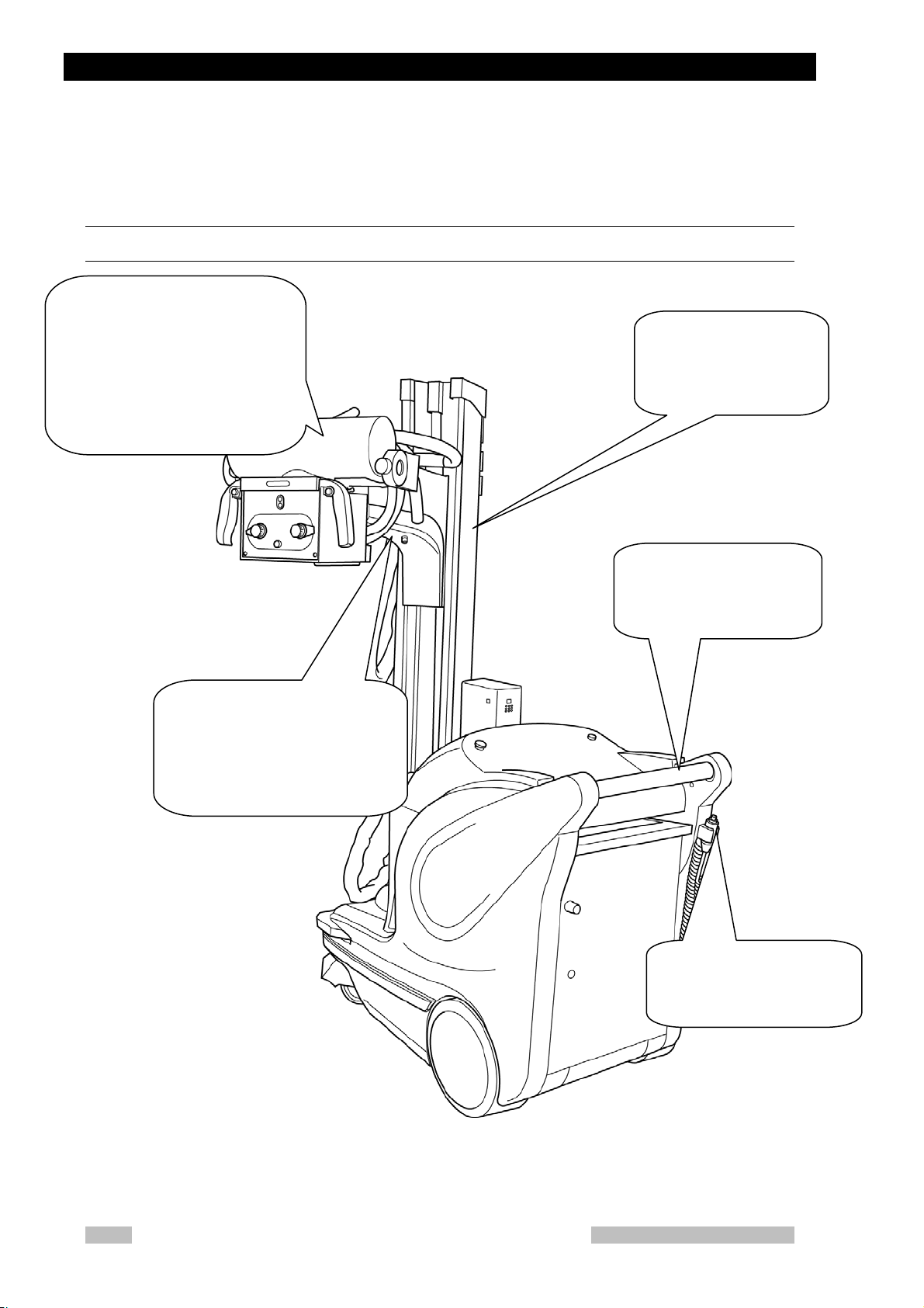
2.3 Name of Each Part of the Unit
Appearance
X-ray tube unit:
The X-ray tube with the collimator
can turn around the X-ray focus.
This makes a positioning and
adjustment of the irradiation field
and small movement of the unit.
Column:
Holds the X-ray tube
assembly and arm. It can
turn itself
Arm:
Holds the X-ray tube assembly. It
can slide vertically along the
column and the arm itself can
stretch in the horizontal direction.
Grip bar(Driving handle):
The handle for the system
driving.
Hand switch:
The switch to make X-ray
exposures
MobileArt Evolution High Power Type(32kW) Installation Manual
2-4
Page 13
Chapter 2 Outline
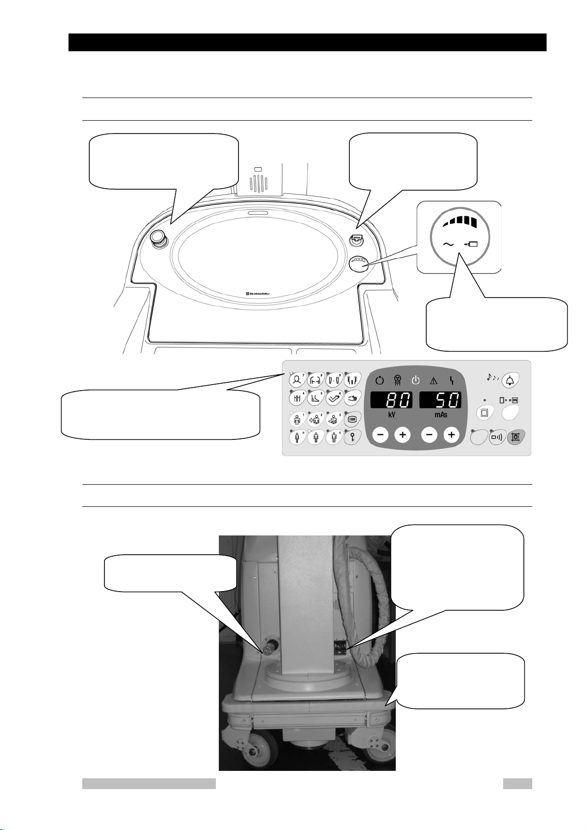
Operating section
Emergency stop switch:
Use to stop the motor in an
emergency case.
X-ray control panel:
Refer to Operation Manual.
Key switch:
Turns the system on/off.
Battery indicator:
Indicate remaining charge of
the battery.
Power plug and main circuit breaker
Power plug:
Use to charge the battery.
Main circuit breaker:
Turning off this breaker cut
off power for the whole unit.
The lid can be opened by
pressing and releasing it.
Obstruction detector:
Stop the unit in the event
of a collision
MobileArt Evolution High Power Type(32kW) Installation Manual
2-5
Page 14

Chapter 2 Outline
2.4 Name of Each Circuit Board and Layout of the
Circuit Boards
Right side of the unit
Left side of the unit
Discharge Switch
Bus Extender
MUX CAPACITOR
BOARD
Xcont-2008
BOARD
NEXSH
BOARD
Breaker NFB1
Under side is ON
MUX-LC1BF
MobileArt Evolution High Power Type(32kW) Installation Manual
2-6
BOARD
MUX
Power 32K
MUX
BOARD
Charge 04B
Inverter Unit
32K
MUX
Charge 32K
BOARD
Page 15

Chapter 2 Outline
Lower part of the unit
MU DRIVER-07
BOARD
MobileArt Evolution High Power Type(32kW) Installation Manual
2-7
Page 16

Chapter 3
Preparations for installation
Before installing the unit, thoroughly read this Chapter and make necessary
preparations.
Chapter Contents
3
3.1 Tools Required for Installation
3.2 Unpacking
3.3 Discharging the Internal Capacitor
3.4 How to Open/Close the Covers
MobileArt Evolution High Power Type(32kW) Installation Manual
3-1
Page 17

Chapter 3 Preparations for installation
3.1 Tools Required for Installation
When installing the unit, prepare the following tools:
• Screw drivers and Philips screw drivers
• Hexagonal bar L-type spanners: No. 2.5~10
• Nipper
• Pliers
• Tester
• Insulok
• Grease
• Cutter
• Waste cloth
• Alligator clip
• Alcohol for cleaning
• Oscilloscope
• Hexagonal bolt M8 x 16: (Only for exchanging X-ray tube assembly)
• Pliers for FU Lock nut AW04: (Only for exchanging X-ray tube
assembly)
• Spring gauge: (Only for adjusting X-ray tube assembly or adjustment
of handle)
3-2
MobileArt Evolution High Power Type(32kW) Installation Manual
Page 18

3.2 Unpacking
3.2 Unpacking
Make sure that the following items are contained:
Quantity Description
MobileArt Evolution type 32kW 1
Components
Options
Arm cover 1
Spare
parts
Operation Manual 1
Installation Manual 1
Parts List 1
Fuse,313.500 1
Fuse,313001 1
Fuse,313002 1
Fuse,313005 1
Fuse,3136.25 1
Fuse,326010 1
Fuse,660CF-10UL 1
Label, Input Voltage 1
Cap 5 White
Cap 2 Blue
Release Switch Label 2
SH_MUX200 S/W 1
Remote controller
Protective screen
Dose area product meter
Dose calculation unit
Distance indicator
Keyless entry
Changing the grip bar height
Luminous hand switch
Additional a hand switch
Grid case
Large cassette box
MobileArt Evolution High Power Type(32kW) Installation Manual
3-3
Page 19

Chapter 3 Preparations for installation
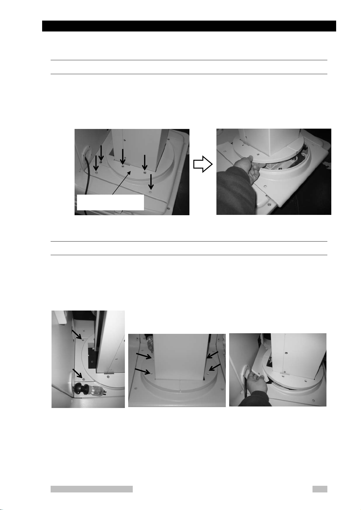
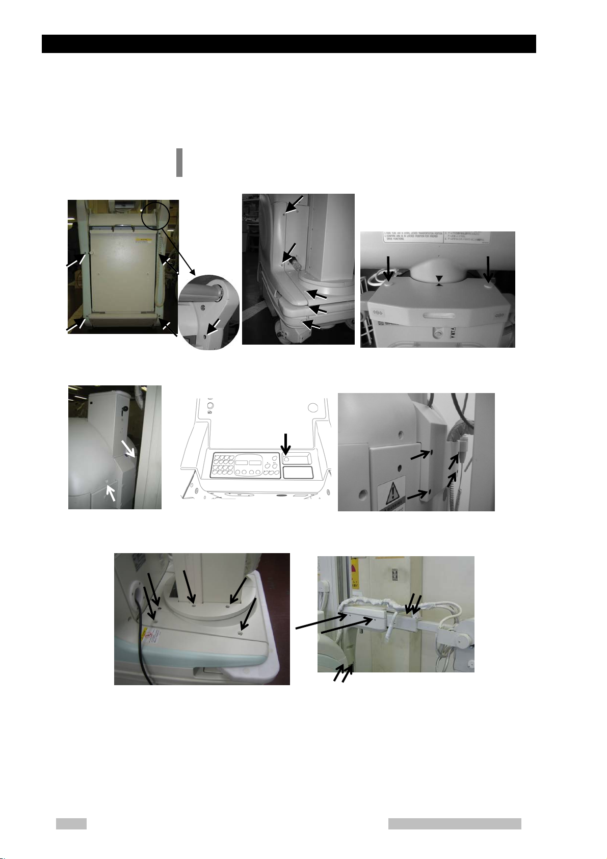
Remove Fixing bracket for device shipment
1. Remove the red plate fixing the column rotation-lock pin. Then, paste the
attached sponge on the place, where the red plate was fixed.
Fixing plate
Fig.3- 1
2. Remove the column rotation-lock pin.
3. Remove both sides of the fixing bracket for Tube rotation-lock and the arm
extension retaining at tip of arm.
Fixing bracket
3-4
Fig.3- 2
MobileArt Evolution High Power Type(32kW) Installation Manual
Page 20

3.2 Unpacking
4. Unscrew the weight fixing bolt. If it is hard to remove, loosen the bolt (a) at
the arm fixing bracket shown in the following figure.
Arm fixing bracket
(a)
Fig.3- 3
(a)
Weight fixing bolt
5. Finally remove the arm fixing bracket.
6. After unpacking, turn ON the main breaker and the switch (see Fig.3- 6),
move to the place, where X-ray radiography is executable and there is a
power outlet. The main breaker is at the front side of the system.
ON
ON
OFF
OFF
Fig.3- 4 Key switch
Fig.3- 5 Main breaker
When the system is parked for long time, this might flat the wheels where
contacts the floor. Runing the system, the wheels will be back the original
shape gradually.
Use the fixing brackets for transportation when the system is transported by
a track etc.
MobileArt Evolution High Power Type(32kW) Installation Manual
3-5
Page 21

Chapter 3 Preparations for installation
3.3 Discharging the Internal Capacitor
In this system, large-capacity capacitors are connected to the battery.
Even after turning OFF the key switch or the main breaker, electrical
charge remains in the capacitor.
Be sure to discharge the capacitor when working on this system.
1. Confirm that both the key switch and the main breaker are turned OFF.
2. Remove the right-side cover.
3. Confirm that the discharge switch is set to “NORMAL” (left side).
4. Disconnect the CN1/CN2 cable from the CN2 connector “NORMAL” on the
MUX CAPACITOR board and connect it to the CN1 connector
“DISCHARGE”. If electrical charge is remaining in the capacitor, the LED
on the MUX CAPACITOR board will be lit.
3-6
Fig.3- 6
5. Set the discharge switch to “DISCHARGE” (right side).
Discharge of the internal capacitor is started.
MobileArt Evolution High Power Type(32kW) Installation Manual
Page 22

3.3 Discharging the Internal Capacitor
7
Fig.3- 7
6. Five minutes or more will be required to reach the capacitor voltage to 1 V
or less. Capacitor voltage can be checked by using check pins CP1-CP2
on the MUX CAPACITOR board.
7. After all work is finished, to return the system to normal operation status,
confirm again that both the key switch and the main breaker are turned
OFF, then set the discharge switch to “NORMAL” (left side), and reconnect
the CN1/CN2 cable to the CN2 connector “NORMAL” on the MUX
CAPACITOR board.
MobileArt Evolution High Power Type(32kW) Installation Manual
3-
Page 23

Chapter 3 Preparations for installation
3.4 How to Open/Close the Covers
Be sure to turn off the main breaker. There is a danger of receiving
electric shock.
Name and Layout of the Covers
Front cover
Top co ver
Side cover
Fig.3- 8 Name and layout of the covers
Arm joint section
Cable cover
Do NOT pull the imaging unit's cable.
If the cable catches on something, do NOT pull on the imaging unit.
Doing so can cause in cable damage, fire, electric shock, unit damage,
or malfunction.
3-8
MobileArt Evolution High Power Type(32kW) Installation Manual
Page 24

3.4 How to Open/Close the Covers
1. Remove eight screws shown in Fig.3- 9.
Fig.3- 9 Points to screw on the side cover
2. Pull the side cover sideways to detach.
Be careful to remove the right side cover. The right side cover and the
main unit are connected with the cable of the hand switch.
MobileArt Evolution High Power Type(32kW) Installation Manual
3-9
Page 25

Chapter 3 Preparations for installation
How to Open/Close the Top cover
1. Unscrew screws as shown in Fig.3- 10 (a).
2. Unscrew screws on the Top cover as shown in Fig.3- 10 (b).
3. Pull up the front part of the top cover (Fig.3- 11).
The top cover and the main unit are connected with the cables. Be
careful to remove the top cover.
(a) (b)
Fig.3- 10 Screw cramp positions of the top cover
3-10
Fig.3- 11 How to open/close the top cover.
MobileArt Evolution High Power Type(32kW) Installation Manual
Page 26
3.4 How to Open/Close the Covers
How to Open/Close the Front Cover
1. Unscrew screws as shown in Fig.3- 12 and remove the top cover to the
side of the unit.
2. Slightly holding up the column under-cover, pull out forward and remove
the cover.
Column under-cover
Fig.3- 12 Method of opening/closing the front cover
How to Open/Close the Front Rear Cover
3. Unscrew 2 screws as shown in Fig.3- 13 (a).
4. Unscrew 4 screws in the column under-cover as shown in Fig.3- 13 (b).
5. Remove the front rear-cover, slightly holding up the column under-cover, as
shown in Fig.3- 13 (c).
(a) (b) (c)
Fig.3- 13 Method of opening/closing the front rear-cover
MobileArt Evolution High Power Type(32kW) Installation Manual
3-11
Page 27

Chapter 3 Preparations for installation
How to Open/Close the Cable Cover
1. Loose 4 hexagon socket head cap screws as shown in Fig.3- 14.
2. Pull the cable cover upward and remove it.
Cable Cover
Fig.3- 14 Screw cramp positions of the cable cover
How to Open/Close the Front Cover
1. Remove the front side cover and front rear cover.
2. Remove the cable cover.
3. Remove the cable guard and cable holder.
4. Remove the code guide.
5. Unscrew 4 screws as shown in Fig.3- 15 and remove the front cover.
3-12
Cable Holder
MobileArt Evolution High Power Type(32kW) Installation Manual
Cable Guard
Fig.3- 15 Screw cramp positions of the front cover
Cord guide
Page 28

3.4 How to Open/Close the Covers
A
How to Open/Close the Arm Joint Section
1. Remove the upper cover and the cable cover.
2. Unscrew the hexagon socket head cap screws at 4 locations indicated in
Fig.3- 17.
3. Remove the knob of the arm lock release lever by turning it
counterclockwise.
4. Pull out the top plate and the main cover of the arm joint section.
Top plate
Main cover of arm joint
section
rm Lock release lever
Cable Cover
Fig.3- 16 Name of each part of the arm joint section
Hexagon socket head
cap screw M4
Fig.3- 17 Screw cramp positions of Top plate
MobileArt Evolution High Power Type(32kW) Installation Manual
3-13
Page 29

Chapter 4
Installation
Install the system properly in the procedures described in this Chapter.
4.1 Installation Procedures
4.2 Check Safety function
4.3 Changing According to the Power Supply
4.4 Checking Performance of Each Part
4.5 Installing the arm cover
4.6 Attaching the knob for locking collimator rotation
4.7 Attaching screw caps
4.8 Installing the apron hanger
4.9 Reset of all parts usage information
4.10 Assembler Test
4.11 Charging the Battery after installation
4
Chapter Contents
In this system, large-capacity capacitors are connected to the battery.
Even after turning OFF the key switch or the main breaker, electrical
charge remains in the capacitor.
Be sure to discharge the capacitor when working on this system.
(Refer to 3.3)
MobileArt Evolution High Power Type(32kW) Installation Manual
4-1
Page 30
Chapter 4 Installation
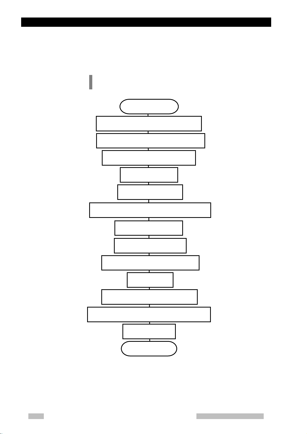
4.1 Installation Procedures
Install the system according to the flowchart below.Fill in the
Installation Performance Check Sheet in accordance with table 4-1.
Changing According to the Power Supply
Checking Performance of Each Part
Attaching the knob for locking collimator rotation
Check Safety function
(Refer to Chapter 5)
Installing the arm cover
Attaching screw caps
Installing the apron hanger
Reset of all parts usage information
Start
(Refer to 4.2)
(Refer to4.3)
(Refer to 4.4)
Installing options
(Refer to4.5)
(Refer to 4.6)
(Refer to 4.7)
(Refer to 4.8)
(Refer to4.9)
Assembler Test
(Refer to 4.10)
4-2
Charging the Battery after installation
(Refer to 4.11)
Explanation of MobileArt Evolution operation to
customer
Clinical application
End
MobileArt Evolution High Power Type(32kW) Installation Manual
Page 31

4.1 Installation Procedures
Table 4- 1 fill-in position of the Installation Performance Check Sheet
Installation
4.2Check Safety function
4.3Changing According to the Power Supply
Aging
Check tube current
Checking Movement
4.4
Chapter 5 Installing options
4.5 Installing the arm cover
4.6 Attaching the knob for locking collimator
of the Collimator Unit
Checking Movement
the Unit
Checking the each
parts movement and
the lock function
rotation
4.7 Attaching screw caps
4.8 Installing the apron hanger
4.9 Reset of all parts usage information
4.10 Assembler Test
4.11 Charging the Battery after installation
Explanation of the operation to customer
Clinical application
Performance
Check Sheet
①
②
③
④
⑤
⑥
⑦
⑨
⑧
⑩
MobileArt Evolution High Power Type(32kW) Installation Manual
4-3
Page 32

Chapter 4 Installation
4-4
MobileArt Evolution High Power Type(32kW) Installation Manual
Page 33

4.2 Check Safety function
4.2 Check Safety function
Check the function of Key switch
Confirm that the key switch is able to be ON/OFF.
Check the fucntion of brake
1. Grip the brake release bar to see the brake can be released.
2. Release the brake bar to see the brake is ON.
Check the function of emergency brake release
1. Turn off the key switch
2. Press the emergency stop switch.
3. Press the emergency brake release switch to release the brake.
Check the function of emergency stop
1. Press the emergency stop switch.
2. It bans the running and x-ray radiography.
MobileArt Evolution High Power Type(32kW) Installation Manual
4-5
Page 34

Chapter 4 Installation
4.3 Changing According to the Power Supply
Change the power plug and the connections of the connector P1
and P2 in the system (Fig.4- 1 ) according to the voltage of the
power supplied to use's place.
1. Turn off the main circuit breaker.
2. Change the power plug according to use's place.
3. Open the right Side cover.
4. Change the connections of the connector P1 and P2 according to Table
4- 2
5. Stick the supply voltage indication label above the outlet of the power
plug. (The label is included in the maintenance parts.)
6. Turn on the main circuit breaker.
7. Make sure the circuit breaker NFB1 is ON (under side).
Be sure to change the connections according to the supply voltage at
the installation site. Charging the battery with wrong connections may
cause burning of the electric parts or fire.
(The connections are set for 100V when the system is shipped from the
factory.)
Table 4- 2 Changing the connection according to supply voltage
Supply voltage
240V±10%
230V±10%
220V±10%
200V±10%
120V±10%
110V±10%
100V±10%
Connector
P1
A0 A240
A+10 A220
A0 A220
A0 A200
A0 A120
A+10 A100
A0 A100
Fig.4- 1 Connector P1 and P2
Connector
P2
XCONT-2008
NEXSH
Connector
P1 and P2
4-6
MobileArt Evolution High Power Type(32kW) Installation Manual
Page 35

4.4 Checking Performance of Each Part
4.4 Checking Performance of Each Part
Make sure of the connections according to the supply voltage at the
installation site before the performance check.
Aging
Perform aging of the system. Make exposures from step 1 to step 11
according to "Table 4- 3".
If anything is wrong with the system during the aging, go back 2-steps.
To measure the tube voltage waveform, check CP9 TKV (tube voltage
feedback signal 1 V/20 kV) of the XCONT-2008 board by using an
oscilloscope.
Table 4- 3 Aging steps
Step
1 60 10 2 40
2 70 10 2 40
3 80 10 2 40
4 90 10 2 40
5 100 10 2 40
6 110 10 2 40
7 115 10 2 40
8 120 10 2 40
9 125 10 2 40
10 130 10 2 40
11 133 10 2 40
Tube voltage
(kV)
Tube current
–time
product(mAs)
Number
of
exposures
Pause time
(Sec.)
While aging, defend enough from the radiation by closing the collimator
completely and using the defense apron or the screen.
MobileArt Evolution High Power Type(32kW) Installation Manual
4-7
Page 36

Chapter 4 Installation
Check tube current
(1) Large focus
(2) Small focus
Check tube current as following steps.
1. Enter the Adjustment mode. (Refer to B.1)
2. Enter the tube current two-point adjustment mode. (See B.4)
3. Check that tube current value displayed on panel is within the range
below. Adjust tube current when the tube current is not within the range.
1. 80kV, 50mA : 45 – 50 mA
2. 80kV, 400mA : 370 – 400mA
1. 80kV, 50mA : 45 – 50 mA
2. 80kV, 200mA : 185 – 200mA
Checking Movement of the Collimator Unit
Make sure that the collimator is correctly mounted.
1. Loose the rotation-lock screw for the collimator.
2. Check that there is no large play on the rotation of the collimator section.
Make sure whether the light field is normal.
1. Turn the Irradiation field adjusting knob completely open.
2. Push the collimator lamp switch and confirm the light field.
3. Turn the Irradiation field adjusting knob completely close.
4-8
4. Push the collimator lamp switch and confirm the light field is completely
shaded.
When matching the centers of the collimator and X-ray focus, refer to
appendix E.7.
MobileArt Evolution High Power Type(32kW) Installation Manual
Page 37

4.4 Checking Performance of Each Part
rotation-lock knob
Arm Lock
Release switch
SID Measure
Irradiation field
adjusting knob
Inch-Mover Buttons
Collimator lamp switch
Fig.4- 2 Name of parts of the collimator
Arm lock
release switch
Irradiation field
adjusting knob
MobileArt Evolution High Power Type(32kW) Installation Manual
4-9
Page 38

Chapter 4 Installation
Checking Movement the Unit
Check functions of the driving handle and the Inch-Mover Buttons.
The Inch-Mover Button is at the front of the collimator.
1. Turn on the key switch.
2. Confirm the system runs forward when pushing the driving handle.
3. Confirm the system runs backward when pulling the driving handle.
4. Push the arm lock release switch and lift up the X-ray tube assembly.
5. Confirm the system moves to correct direction when pushing the
Inch-Mover Buttons.
6. Confirm the system stops when pushing the both Inch-Mover Buttons at
the same time.
The Inch-Mover Buttons do not work when the driving handle is pushed or
pulled, because safety function works.
Inch-Mover Button
(To Forward)
Inch-Mover Button
(To Backward)
4-10
Fig.4- 3 Inch-Mover Button
MobileArt Evolution High Power Type(32kW) Installation Manual
Page 39

4.4 Checking Performance of Each Part
Checking the each parts movement and the lock function
Checking the arm stretch, up/down and rotation.
1. Move the stretch, up/down and rotation of the arm with pressing the “Arm
Lock Release Button”. Confirm whether there is neither abnormal noise
nor stroke shortage.
2. Confirm the arm locks when “Arm Lock Release Button" is released.
MobileArt Evolution High Power Type(32kW) Installation Manual
4-11
Page 40

Chapter 4 Installation
4.5 Installing the arm cover
Installation procedure of arm cover
1. Lift up the arm and expand it.
2. Remove the Cable Guide from the Middle Arm. (M5 bolt, 4places. Fig.4- 4
(c))
3. Attach the Upper arm cover to the Arm. (M4 screw, 4places, Fig.4- 4
(d))
4. Attach the Lower arm cover to the Arm. (M4 screw, 6places, Fig.4- 4 (e))
5. Attach the Cable Guide to the Middle arm. (Fig.4- 4 (f))
(b) (c)
M4 screw (4 places)
Upper arm cover
M4 screw (6 places)
Cable guide
4-12
(d) (e) (f)
Fig.4- 4 Procedures to attach the arm cover
MobileArt Evolution High Power Type(32kW) Installation Manual
Lower arm cover
Page 41

4.6 Attaching the knob for locking collimator rotation
4.6 Attaching the knob for locking collimator
rotation
Attach a knob for locking collimator rotation. It is packed together with screws
for adjustment of X-ray axis.
Fig.4- 5 Attaching the knob for locking collimator rotation
MobileArt Evolution High Power Type(32kW) Installation Manual
4-13
Page 42
Chapter 4 Installation
4.7 Attaching screw caps
Attach screw caps to places shown in Fig.4- 6 . Screw caps are
included in spare parts.
Side cover: 8 places (16 places in total for left and right) Collimator upper part: 2 places
Top cover: 3 places Cable cover: 4 places
4-14
Front cover: 4 places, Front rear cover: 2 places, Arm cover: 6 places
Support stand cover: 4 places 10 places in total Middle arm part: 2 places
Fig.4- 6 Places to attach screw caps
MobileArt Evolution High Power Type(32kW) Installation Manual
Page 43

4.8 Installing the apron hanger
Ap
r
4.8 Installing the apron hanger
Do when the user wants to change the position where the apron hanger is
installed.
Installation procedure of the apron hanger
1. Remove 2 screws from the upper surface of top cover, and remove the
top cover.
2. Remove the screw which installs the apron hanger, and install the apron
hanger in the arbitrary position shown in Fig.4- 7.
Top cover
ron hange
Position where apron
hanger can be installed
Fig.4- 7 Apron hanger
4.9 Reset of all parts usage information
Clear all parts usage information from the system by Usage information
collective setting mode(refer to B.18)
4.10 Assembler Test
In USA, execute the assembler test according to the ASSEMBLER
TEST MANUAL (Document No.M503-E330).
MobileArt Evolution High Power Type(32kW) Installation Manual
4-15
Page 44

Chapter 4 Installation
4.11 Charging the Battery after installation
• Check the charge function and LED display functions correctly.
• In order to make the battery stable after installation, charge the battery after
using it as much as the red LED of the battery indicator comes on. Instruct
users of the system to repeat three times the cycle of charging and
discharging the battery. (Refer to operation manual.)
• The battery remaining amount is decreasing due to the natural discharge
during the time from factory shipment to the installation and also the
discharge of installation procedure. Please explain to the user that if starts
using the device without charging, the recharging will be needed earlier than
usual.
4-16
MobileArt Evolution High Power Type(32kW) Installation Manual
Page 45

Chapter 5
Installing the Options
How to install the options is described in this Chapter.
Chapter Contents
5.1 Installing Remote Controller Option
5.2 Installing folding–type Protective Screen Option
5.3 Installing Dose Area Product Meter Option
5.4 Installing Dose Area Product Meter Option for UL
5.5 Installing the Dose Calculation Unit
5.6 Installing the Distance Indicator
5.7 Keyless Entry
5.8 Adjusting the Height of the Driving Handle
5.9 Illuminated Hand Switch
5.10 Additional Hand Switch
5.11 Installing the Grid Case Option
5.12 Installing the Large Cassette Box Option
5.13 FPD Upgrade Kit
5.14 Decoration label
5
MobileArt Evolution Installation Manual
5-1
Page 46
Chapter 5 Installing the Options
5.1 Installing Remote Controller Option
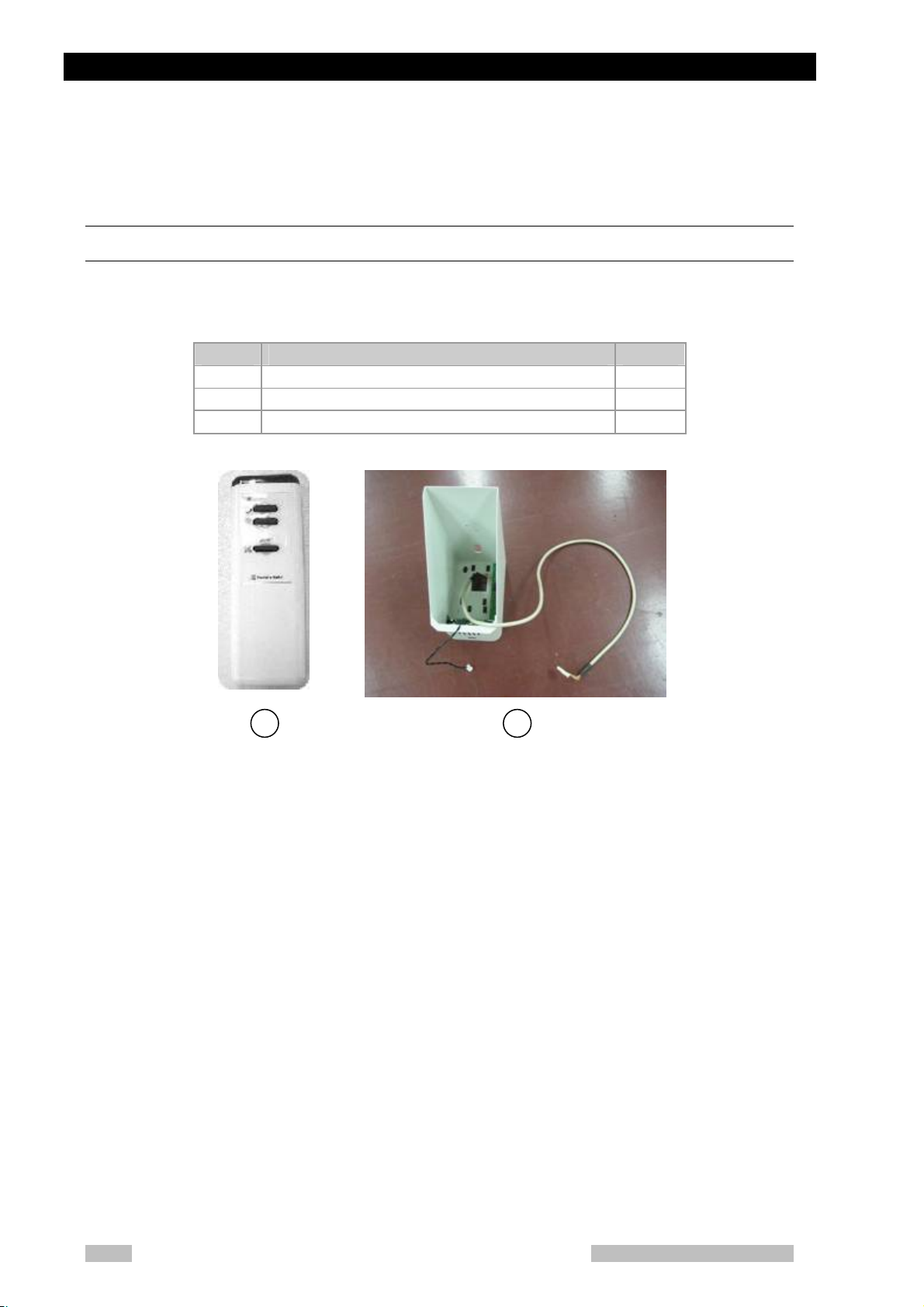
Component of Remote Controller Option
The Remote controller option consists of the following parts. Make sure that all
these parts are contained in the package.
Parts Name Quantity
1 RC Transmitter 1
2 Receiver ASSY 1
3 AA battery 2
1 2
Fig. 5-1 Component of Remote controller option
5-2
MobileArt Evolution High Power Type(32kW) Installation Manual
Page 47

5.1 Installing Remote Controller Option
Mounting the Receiver Assy
Procedures for mounting the Receiver Assy
1. Remove the side covers, the top cover and the cover of the arm joint
section. (Refer to Chapter 3.)
2. Mount the Receiver Assy in place of the removed cover of the arm joint
section. Use the resin top cover and socket head bolt that have been
attached as they are.
3. Connect and layout the cable extending from the photo-receptor for the
remote controller to JREM of XCONT-2008 board as shown in Fig. 5-2.
4. Turn on the DIP switch SW3-4 on the NEX-SH board.
5. Connect the speaker’s cable.
6. Attach the removed covers again.
JREM
JREM
Fig. 5-2 Wiring to the XCONT-2008 board for the remote controller option
JREM
XCONT 2008
NEXSH
CPU
MobileArt Evolution High Power Type(32kW) Installation Manual
5-3
Page 48

Chapter 5 Installing the Options
Checking Performance of the Remote Controller
Open the lid at the back of the remote controller, and insert two "B" size batteries.
To enable the function of the remote controller, push the remove controller
Button on the X-ray operation panel and LED is illuminated. (Fig. 5-3 ).
After preparations, check the performance of the keys listed in Table 1.
Transmit from the gray area shown in Fig. 5-5 to the arm attaching part.
Fig. 5-3 Remote Controller switch
Table 1 Name and basic function of each key of the remote controller
Key Name Normal function
① Exposure preparation
switch
② Exposure switch Pressing this switch together with the exp osure
③ Collimator lamp switch Turns on/off the collimator lamp.
1 2 3
Starts the preparation for exposures.
preparation switch makes exposures.
5-4
Fig. 5-4 Remote controller
MobileArt Evolution High Power Type(32kW) Installation Manual
Page 49

5.1 Installing Remote Controller Option
Fig. 5-5 Range where remote control can be operated
270°,Radius 5m
MobileArt Evolution High Power Type(32kW) Installation Manual
5-5
Page 50

Chapter 5 Installing the Options
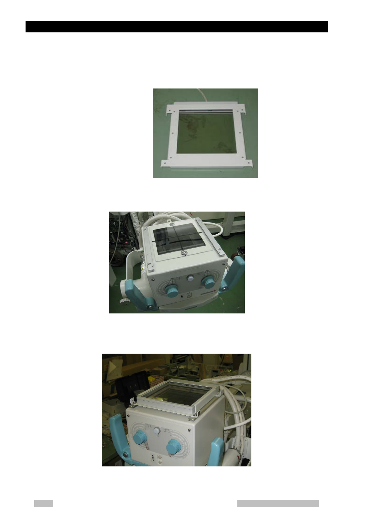
5.2 Installing folding–type Protective Screen
Option
Component of folding-type Protective Screen Option
The Protective screen option consists of the following parts. Make sure that all
these parts are contained in the package.
Parts Name Quantity
1 Protective screen assy 1
2 Top plate 1
3 S-shape large washer D16M4 (accessory) 3
4 SEMS SCREW M4x10(accessory) 3
5 BUMPER, SJ-5303 CLEAR 2
6 BUMPER, SJ-5023 WHITE 2
7 Pattern paper 2
①
Fig. 5-6 Folding-type Protective Screen Option
⑦
⑥
⑤
5-6
MobileArt Evolution High Power Type(32kW) Installation Manual
Page 51

5.2 Installing folding–type Protective Screen Option
7
A
A
A
Installation of the Protective Screen Option
7. Remove the top plate and the knob of the arm lock release lever, then
remove the top plate joint cover and the spacers.
Spacer
rm lock release
lever knob
Fig. 5-7 Remove the joint cover
Top plate
rm lock joint
section cover
Top co ver
Screws
rm lock joint section cover
8. Mount the joint section cover. Attach the knob of the arm lock release lever,
and put the Protective screen on the joint section cover, and fix the
Protective screen with the washers [3] and the SEMS screws M4 [4] (three
points).(Fig. 5-8)
Protective screen
[3] [4]
Fig. 5-8 Installing the protective screen
9. Attach the top plate on the Protective screen and fix the protective screen.
MobileArt Evolution High Power Type(32kW) Installation Manual
Top plate
Fig. 5-9 Installing the protective screen
5-
Page 52

Chapter 5 Installing the Options
10. Using the pattern paper [7], paste two types of bumper [5] and [6] onto two
places on upper cover sheet panel.
How to paste
a. See the side [A], [B] shown on the pattern paper [7], and face it respectively to
the bottom and lateral side of the upper cover sheet panel, then paste by the
tape.
B side
A side
Fig. 5-10 Pasting the pattern paper
b. Paste the bumpers respectively at the place shown in the following figure,
matching the paper shape.
⑥bumper
⑤bumper
Fig. 5-11 Bumpers pasting position
c. When the bumpers are pasted completely, remove the paper.
Fig. 5-12 Bumpers pasting position
5-8
MobileArt Evolution High Power Type(32kW) Installation Manual
Page 53

5.2 Installing folding–type Protective Screen Option
Checking movement of the Folding-type protective screen option
Set up and down the protective screen several times.
Check the movement is nomally or not.
Confirm that the protective screen correctly contacts to bumpers pasted on the
upper cover sheet panel so that this protects the contact of the sheet panel.
MobileArt Evolution High Power Type(32kW) Installation Manual
5-9
Page 54

Chapter 5 Installing the Options
5.3 Installing Dose Area Product Meter Option
Component of Dose Area Product Meter Option
The Dose Area Mater Option consists of the following parts. Make sure that all
these parts are contained in the package.
No Parts Name Quantity
1 Dose Area Product Meter Adapter 1
2 Dose display panel 1
3 Sub Weight 2
4 DAP relay cable A 1
5 DAP relay cable B 1
The Dose Area Product Meter is not included. Purchase it separately.
Installing Dose Area Product Meter Option
Procedures of mounting
1. Remove 2 plates fixed in Dose Area Product Meter.
Fig. 5-13
unscrew
5-10
MobileArt Evolution High Power Type(32kW) Installation Manual
Page 55

5.3 Installing Dose Area Product Meter Option
2. Fix the Dose Area Product Meter to the adapter by the screw which was
removed previous step.
Fig. 5-14 Fixing Dose Area Product Meter
3. Remove the collimator rail.
Fig. 5-15
4. Fix together the collimator rail and adapter.
Fig. 5-16
MobileArt Evolution High Power Type(32kW) Installation Manual
5-11
Page 56

Chapter 5 Installing the Options
A
5. Detach the arm cover.
Fig. 5-17 Detach the arm cover
rm cover
6. Connect the DAP relay cable B from the connector of Dose Area Product
Meter to the relay connector of the Arm section. Wire the DAP relay cable
B along the collimator cable. (Leave the wire of shield free.) (Fig. 5-18 and
Fig. 5-19)
The Dose meter cable from the system to the arm is already wired at the
factory.
DAP relay cable B
Relay connector
To the Dose Area
Product Meter
Fig. 5-18 Wiring under the arm
DAP relay cable B
To the arm
Relay connector
Fig. 5-19 Connecting with connector
5-12
MobileArt Evolution High Power Type(32kW) Installation Manual
Page 57

5.3 Installing Dose Area Product Meter Option
7. Connect DAP relay cable A between the connector of dose meter at the
unit and XCONT board JDAP connector. (Leave the wire of shield free.)
DAP relay cable B
DAP relay cable A
Dose display panel
DAP
Display panel cable
Dose meter cable
(Wired of factory)
Fig. 5-20
MobileArt Evolution High Power Type(32kW) Installation Manual
5-13
Page 58

Chapter 5 Installing the Options
Adjustment of vertical motion balance
Adjustment procedure
1. The column top cover is detached.
2. The arm is lowered most below, and the weight in the column is lifted to the
uppermost part.
Fig. 5-21 Positioning of arm
3. Two sub weights are installed, and the vertical motion balance of the arm
part is adjusted.
Fig. 5-22 Installing section of sub weights
Sub weight
Nut
5-14
MobileArt Evolution High Power Type(32kW) Installation Manual
Page 59

5.3 Installing Dose Area Product Meter Option
Installing the Dose Display Panel
Installing procedure
1. Remove the upper cover and the left side cover
2. Remove the cover shown in Fig. 5-23 and attach the dose display panel
Cover
Fasten with nuts
Fig. 5-23 Installing the Dose Display Panel
3. Connect the cable supplied with the dose display panel to the JDOSE
connector on the X-CONT board. (Leave the wire of shield free.)
4. Re-attach the upper cover and the left side cover.
Setting of DIP Switch
Set the Dip switch SW3-5 to “ON” on the NEX-SH Board.
Operation check of Dose Area Product Meter
Operation check of Dose Area Product Meter
1. Turn ON the power.
2. Following the adjustment method of the Dose Area Product Meter
described in Appendix B.12, adjust the Dose Area Product Meter.
3. When adjusted completely, operate the Dose Area Product Meter to check
that the Dose Area Product Meter works correctly.
MobileArt Evolution High Power Type(32kW) Installation Manual
5-15
Page 60

Chapter 5 Installing the Options
Be sure to follow the adjustment method of the Dose Area Product Meter
when adjust the Dose Area Product Meter.
If the Dose Area Product Meter is used without adjustment, the Dose Area
Product might not be detected correctly.
The unit of the Dose Area Product at the display is “mGy・cm2”.
The unit of the Dose Area Product for the DICOM image header is “dGy・
cm2”.
5-16
MobileArt Evolution High Power Type(32kW) Installation Manual
Page 61
5.4 Installing Dose Area Product Meter Option for UL
7
5.4 Installing Dose Area Product Meter Option for
UL
Component of Dose Area Product Meter Option for UL
The Dose Area Product Meter Option consists of the following parts. Make sure
that all these parts are contained in the package.
No Parts Name Quantity
1 Distance piece for Dose Area Product Meter 1
2 Dose Area Product Meter Adapter 1
3 Dose display panel 1
4 Sub Weight 2
5 DAP relay cable A 1
6 DAP relay cable B 1
7 Screw, SST HEXSOCH Buttom M4x6 4
8 M3X12 hexagonal head cap screw 4
The Dose Area Product Meter is not included. Purchase it separately.
Installing Dose Area Product Meter Option for UL
Procedures of mounting
1. Remove two plates fixed in Dose Area Product Meter.
Fig. 5-24
unscrew
MobileArt Evolution High Power Type(32kW) Installation Manual
5-1
Page 62
Chapter 5 Installing the Options
2. Fix the Dose Area Product Meter to the adapter by the screw, which was
removed previous step.
Fig. 5-25 Fixing Dose Area Product Meter
3. Remove the collimator rail.
Fig. 5-26
4. Fix together the collimator rail and adapter by M3X10 hexagonal head cap
screw.
Fig. 5-27
5-18
MobileArt Evolution High Power Type(32kW) Installation Manual
Page 63

5.4 Installing Dose Area Product Meter Option for UL
A
5. Attach Distance piece for Dose Area Product Meter by M4 HEXSOCH
screw.
6. Detach the arm cover.
Fig. 5-28 Detach the arm cover
rm cover
7. Connect the DAP relay cable B from the connector of Dose Area Product
Meter to the relay connector of the Arm section. Wire the DAP relay cable
B along the collimator cable.
The Dose meter cable from the unit to the arm is already wired at the
factory.
The cable is relayed under the arm.
DAP relay cable B
To the Dose Area
Product Meter
MobileArt Evolution High Power Type(32kW) Installation Manual
Relay connector
Fig. 5-29 Wiring under the arm
5-19
Page 64

Chapter 5 Installing the Options
To the arm
DAP relay cable B
Relay connector
Fig. 5-30 Connecting with connector
8. Connect DAP relay cable A between the connector of dose meter at the
unit and XCONT board JDAP connector.
DAP relay cable B
DAP relay cable A
Dose display panel
Display panel cable
DAP
Dose meter cable
(Wired of factory)
Fig. 5-31
5-20
MobileArt Evolution High Power Type(32kW) Installation Manual
Page 65

5.4 Installing Dose Area Product Meter Option for UL
Adjustment of vertical motion balance
Adjustment procedure
1. The column top cover is detached.
2. The arm part is lowered most below, and the weight in the column is lifted
to the uppermost part.
Fig. 5-32 Positioning of arm
3. Two supplementary weights are installed, and the vertical motion balance
of the arm part is adjusted.
Fig. 5-33 Installing section of sub weights
Supplementary weight
Nut
MobileArt Evolution High Power Type(32kW) Installation Manual
5-21
Page 66
Chapter 5 Installing the Options
Installing the Dose Display Panel
Installing procedure
1. Remove the top cover and the left side cover
2. Remove the cover shown in Fig. 5-34 and attach the dose display panel
3. Connect the cable supplied with the dose display panel to the JDOSE
4. Re-attach the top cover and the left side cover.
Setting of DIP Switch
Set the Dip switch SW3-5 to “ON” on the NEX-SH Board.
Fasten with nuts
Cover
Fig. 5-34 Installing the Dose Display Panel
connector on the X-CONT PCB.
5-22
Operation check of Dose Area Product Meter for UL
Operation check of Dose Area Product Meter
1. Turn ON the power.
2. Following the adjustment method of the Dose Area Product Meter
described in Appendix B.14, adjust the Dose Area Product Meter.
3. When adjusted completely, operate the Dose Area Product Meter to check
that the Dose Area Product Meter works correctly.
MobileArt Evolution High Power Type(32kW) Installation Manual
Page 67

5.4 Installing Dose Area Product Meter Option for UL
Be sure to follow the adjustment method of the Dose Area Product Meter
when adjust the Dose Area Product Meter.
If the Dose Area Product Meter is used without adjustment, the Dose Area
Product might not be detected correctly.
The unit of the Dose Area Product at the display is “mGy・cm2”.
The unit of the Dose Area Product for the DICOM image header is “dGy・
cm2”.(Only for FPD upgrade)
MobileArt Evolution High Power Type(32kW) Installation Manual
5-23
Page 68

Chapter 5 Installing the Options
5.5 Installing the Dose Calculation Unit
Component of the Dose Calculation Unit
The Dose Caluculation Unit consists of the following parts; Make sure that all
these parts are contained in the package.
No Parts Name Quantity
1 Dose Caluculation Unit 1
2 Bracket 2
3 Cover 1
4 Calculation dose display panel 1
5 Display cable 1
6 SESD cable B 1
7 Screw, SST HEXSOCH Buttom M4x6 4
8 Screw, SST FLAT HEAD M3x12 2
9 Sub Weight 2
Installing the Dose Calculation Unit
Procedure to install the Dose Calculation Unit
1. Rotate the collimator to face upwards.
2. Remove the M3 bolts from the rail indicated in Fig. 5-36 and remove the rail.
Fig. 5-35 Dose Calculation Unit
M3 bolts × 2
Remove this rail.
5-24
Fig. 5-36 Remove the Collimator Rail
MobileArt Evolution High Power Type(32kW) Installation Manual
Page 69

5.5 Installing the Dose Calculation Unit
3. At the left side of the collimator, fix together the bracket [2] and the rail by
M3 bolt, which was unscrewed before.
[2] Bracket
Rail
Fig. 5-37 Left side of the Collimator
4. At the right side of the collimator, fix together the bracket [2], the rail, and
the cover [3] in order by the attached Flat head screw M3X12.
Cover [3] Bracket [2]
M3X12 Flat head screw
Fig. 5-38 Right of Collimator
Left
Fig. 5-39 Final figure of Collimator
Rail
Right
MobileArt Evolution High Power Type(32kW) Installation Manual
5-25
Page 70

Chapter 5 Installing the Options
5. Fix the Dose Calculation Unit to the collimator by the attached M4
HEXSOCH screw.
(a)Standard (b)UL version
Fig. 5-40 Mounting the Dose Calculation Unit
6. Finally wire the cables.
Fig. 5-41 Completion of the Dose Calculation Unit mounted
7. Remove the arm cover.
5-26
Fig. 5-42 Arm cover
MobileArt Evolution High Power Type(32kW) Installation Manual
Arm cover
Page 71

5.5 Installing the Dose Calculation Unit
7
8. Connect the dosimeter cable and the SESD cable A at the base part of the
arm using the attached relay cable. (Leave the wire of shield free.)
Connect cables like Fig. 5-43.
SESD cable A
Dosimeter cable
SESD cable B
Fig. 5-43 Cable connection
9. Attach again the arm cover.
10. Connect the unit side connector of dosimeter cable to XCONT board
connector JUSD. (Leave the wire of shield free.)
MobileArt Evolution High Power Type(32kW) Installation Manual
5-2
Page 72

Chapter 5 Installing the Options
Adjustment of vertical motion balance
Adjustment procedure
1. The column top cover is detached.
2. The arm part is lowered most below, and the weight in the column is lifted
to the uppermost part.
3. Two supplementary weights are installed, and the vertical motion balance
of the arm part is adjusted.
Fig. 5-44 Installing section of sub weights
Supplementary weight
Nut
5-28
MobileArt Evolution High Power Type(32kW) Installation Manual
Page 73

5.5 Installing the Dose Calculation Unit
Installing the Dose Display Panel
Installing procedure
1. Remove the upper cover and the left side cover
2. Remove the cover shown in Fig. 5-45 and attach the dose display panel
Cover
3. Connect the cable supplied with the dose display panel to the JDOSE
4. Re-attach the top cover and the left side cover.
Setting of DIP switch
Set the DIP switch SW3-5 to “OFF” on the NEX-SH board.
Fasten with nuts
Fig. 5-45 Installing the Dose Display Panel
connector on the X-CONT board. (Leave the wire of shield free.)
To run the dose calculation unit be sure to set SW3-5 (Dose Area Product
Meter) OFF at NEX-SH board. When SW3-5 is ON, the dose calculation unit
cannot run.
MobileArt Evolution High Power Type(32kW) Installation Manual
5-29
Page 74

Chapter 5 Installing the Options
Operation check of dose calculation unit
Operation check of dose calculation unit
1. Turn the key switch on.
2. Calibrate the Dose Calculation Unit in accordance with “B.13 Dose
Calculation Adjustment Mode”.
3. Check the performance of the Dose Calculation Unit.
Calibrate the dose calculation unit after the installation.
Without the calibration, the dose calculation unit might not function correctly.
5-30
MobileArt Evolution High Power Type(32kW) Installation Manual
Page 75

5.6 Installing the Distance Indicator
5.6 Installing the Distance Indicator
The Distance indicator is used in combination with the Dose calcuration unit.
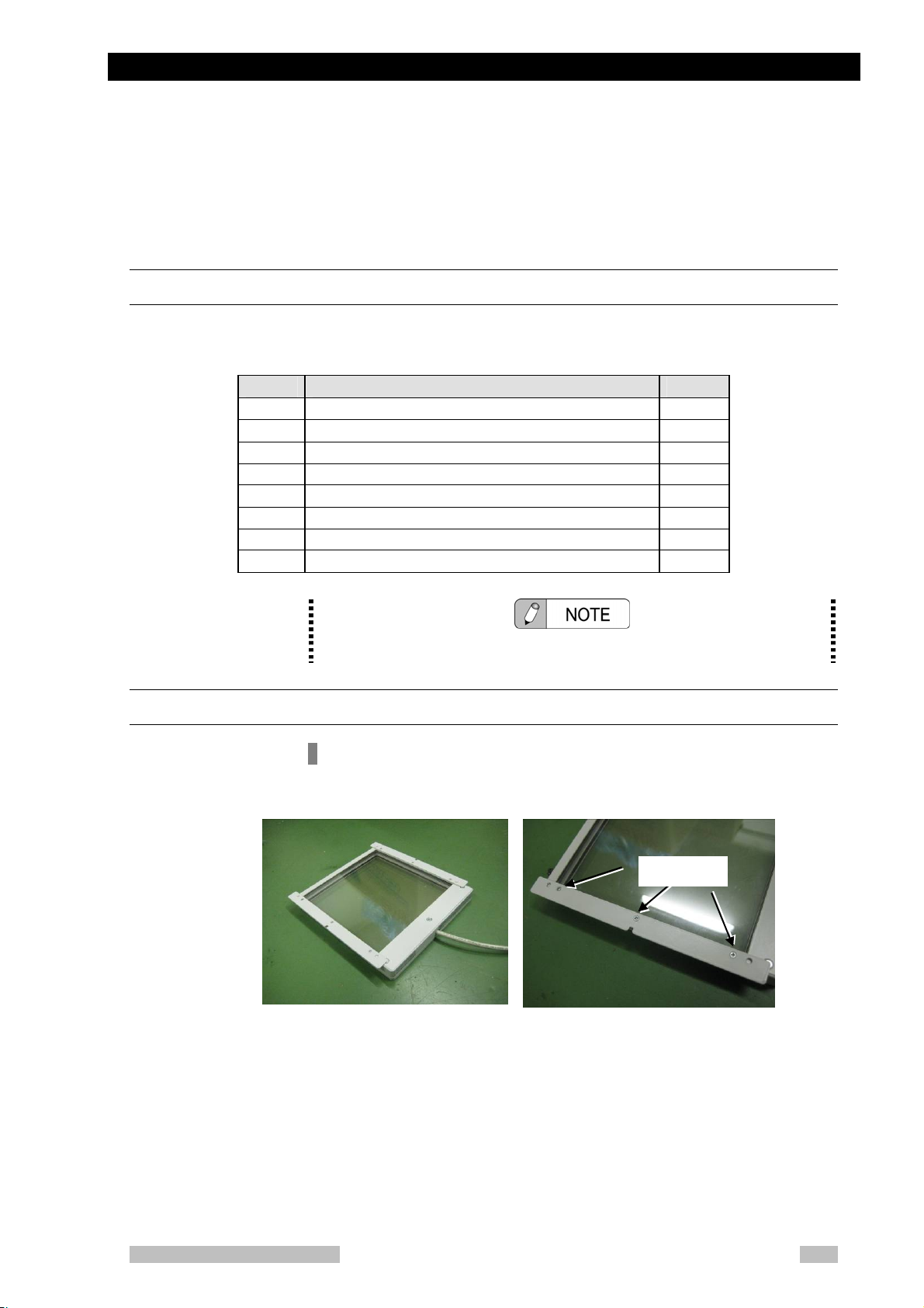
Component of the Distance Indicator
The distance indicator consists of the following parts; Make sure that all these
parts are contained in the package.
No Parts Name Quantity
1 Cover with distance indicator 1
2 Distance Indicator PCB 1
3 Spacer 4
4 SEMS screw M4x8 4
Installing the Distance Indicator
Procedure to install the Distance Indicator
1. Remove the cover with the status indicator lamp from the top of the
collimator.
Loosen the screws. Slide the cover slightly forward and then lift it off.
Loosen the screws and remove the cover.
Fig. 5-46 Collimator Unit
MobileArt Evolution High Power Type(32kW) Installation Manual
5-31
Page 76

Chapter 5 Installing the Options
A
2. Disconnect the connector for the status indicator lamp in the cover.
Fig. 5-47 Location of the Connector
3. Rotate the collimator to face upwards.
Connector
Fig. 5-48
4. Remove the screws indicated in Fig. 5-49 and remove the collimator lamp
cover and the collimator cover.
Collimator Lamp Cover
3 Positions
Fig. 5-49 Collimator Lamp Cover and Collimator Cover
Collimator Cover
lso on opposite side
4 positions
5-32
MobileArt Evolution High Power Type(32kW) Installation Manual
Page 77

5.6 Installing the Distance Indicator
5. Pass the cable from the cover with the distance indicator through the
collimator and connect it to the connector for the status indicator lamp.
Fig. 5-50 Cable Connections
Cover with distance indicator
6. Attach the cover with distance indicator.
7. Attach the collimator cover and the collimator lamp cover.
Fig. 5-51 Distance Indicator
8. Wire the distance indicator cable along the cable of the Dose calculation
unit to the base of the arm.
Fig. 5-52 Wiring the Cable
MobileArt Evolution High Power Type(32kW) Installation Manual
5-33
Page 78

Chapter 5 Installing the Options
9. Remove the arm cover.
Fig. 5-53
10. Attach the Distance Indicator board with the spacer at the bottom of the
arm.
Arm Cover
Fig. 5-54 Distance Indicator board
Distance Indicator board
11. Connect the dosimeter cable, SESD cable A and distance indicator
cable to the Distance Indicator board, as shown in the diagram. (Leave
the wire of shield free.)
Distance
indicator cable
5-34
Dosimeter cable
(Wired at factory)
MobileArt Evolution High Power Type(32kW) Installation Manual
Distance indicator
board
SESD cable A
Dose calculation unit
Fig. 5-55 Connections to the Distance Indicator board
Distance
Indicato
Page 79

5.6 Installing the Distance Indicator
12. Check setting of DIP switches in accordance with following table.
Switch name SW1-1 SW1-2 SW1-3 SW1-7
ON/OFF OFF ON ON OFF
Switching the displayed unit.
Contents Setting of offset value
OFF:「cm」
ON:「inch」
13. Move objects away from around the system. Set the Arm position so
that the distance from floor to the focus is 1m.
14. Calibrate the distance indicator board. The gain correction is possible
by setting DIP switches. Set the Gain correction value so that the
distance indicator shows 100cm±2cm.
Switch name SW1-4 SW1-5 SW1-6 Correction value
ON/OFF
OFF OFF OFF 0
ON OFF OFF +2
OFF ON OFF +4
ON ON OFF +6
OFF ON ON 0
OFF ON ON -2
OFF ON ON -4
OFF ON ON -6
15. Attach the Arm cover.
MobileArt Evolution High Power Type(32kW) Installation Manual
5-35
Page 80

Chapter 5 Installing the Options
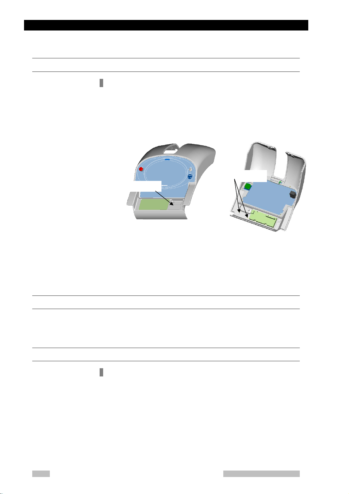
5.7 Keyless Entry
Keyless entry configuration
Keyless entry is composed of the following parts. Check them when unpackage.
No. Item Qty.
1 Keyless switch 1
2 Fixing plate 1
Mount Keyless entry
1. Remove the upper cover.
2. Remove the yellow rotation-lock cover of key switch, turn the stop lever to
Fig. 5-56
How to mount Keyless entry
disassemble the key switch.
5-36
Fig. 5-57 Mounting Keyless switch
MobileArt Evolution High Power Type(32kW) Installation Manual
Page 81

5.7 Keyless Entry
7
3. Unscrew two flange nuts from the rear side, then remove the key switch
and the fixing bracket.
Fig. 5-58
4. Disassemble the removed key switch and remove the rotation-lock ring in
order to use it when mount the keyless switch.
Fig. 5-59
5. Fix the keyless switch fixing bracket from the rear side of main panel by the
flange nut which was removed previous step.
Fig. 5-60
MobileArt Evolution High Power Type(32kW) Installation Manual
5-3
Page 82

Chapter 5 Installing the Options
6. Insert the keyless switch from the front side of main panel and fix it by the
rotation-lock ring and the resin nut from the rear side. Mount the switch
placing the switch lever’s white mark directly below.
Fig. 5-61
Be carefull the direction to fix the rotaion-lock ring. The projecting part is for
fixing at the fixing plate.
Be sure to surely put the projecting part of rotation-lock ring in the notch of
fixing plate.
Otherwise, the switch part might be rotated.
7. Reassemble the keyless switch in the reverse order of the step 2.
5-38
Fig. 5-62
MobileArt Evolution High Power Type(32kW) Installation Manual
Page 83

5.7 Keyless Entry
8. Attach again the upper cover.
Setting of DIP switch
Set the DIP switch SW3-2 to “ON” the NEX-SH board. (Refer to Appendix A)
Fig. 5-63
MobileArt Evolution High Power Type(32kW) Installation Manual
5-39
Page 84

Chapter 5 Installing the Options
5.8 Adjusting the Height of the Driving Handle
The Driving Handle Height Adjustment Option comprises the following parts:
Make sure that all these parts are contained in the package.
No Parts Name Quantity
1 Handle Option ASSY 1
2 Handle Arm 60R 1
3 Handle Arm 60L 1
4 Handle Arm 40R 1
5 Handle Arm 40L 1
6 Handle Arm Cover 60 1
7 Handle Arm Cover 40 1
8 Guide R 1
9 Guide L 1
10 SKM2 1
11 Hexagon Socket Head Screw M6X16 4
Changing the Set Height
The Handle Option ASSY increases the handle height by 90 mm. If the customer
wishes to increase the height by 40 mm or 60 mm, replace the handle arm and
handle cover.
1. Remove the handle arm cover, joint ASSY.
Photosensor
cable
Joint ASSY
Handle arm
5-40
Fig. 5-64
MobileArt Evolution High Power Type(32kW) Installation Manual
Handle arm
cover
Page 85

5.8 Adjusting the Height of the Driving Handle
j
2. Fix the brake bar and the grip by tape etc.
Without fixing the brake bar and the grip by tape etc,the brake bar and the
grip go into pieces.
3. Pull the photosensor cable out of the hole in the handle arm and then
remove the handle arm.
Fig. 5-65
4. Attach the handle arm for the required driving handle height. At this stage,
temporarily fasten the handle arm and don’t attach screw caps. Take care
not to trap the cables.
5. Pass the photosensor cable through the handle arm as shown in Fig. 5-66.
6. Attach the joint ASSY
Temp ora ry
oint
Fig. 5-66
MobileArt Evolution High Power Type(32kW) Installation Manual
5-41
Page 86

Chapter 5 Installing the Options
7. Attach the handle arm cover.
Fig. 5-67
5-42
MobileArt Evolution High Power Type(32kW) Installation Manual
Page 87

5.8 Adjusting the Height of the Driving Handle
Replacing the Handle
1. Open the left and right side covers.
2. Remove the photosensor connector and ground cable.
3. Remove the handle cover and guide. Remove the standard handle.
Handle cover
Guide
Fig. 5-68
4. Pass the handle cover through the High Handle ASSY, as shown in Fig.
5-69. Place it on the handle base and attach the optional guide. (Install the
guide in contact with the 3 contact faces on the handle base.)
Guide
(Option)
Fig. 5-69
MobileArt Evolution High Power Type(32kW) Installation Manual
5-43
Page 88

Chapter 5 Installing the Options
5. Make sure that the clearance between slide plate and guide is 0.2 - 0.5mm.
If the clearance is out of range, make adjustments to the clearance by
loosening the fixing screws.
Guide
Fig. 5-70
Slide plate
0.2-0.5mm
6. Confirm that the handle moves smoothly. Fully tighten the arm screws.
Fig. 5-71
7. Connect the photosensor connector and ground cable.
8. Lift the circuit breaker to turn on the power. Check the travel operation.
9. Close the side covers.
5-44
MobileArt Evolution High Power Type(32kW) Installation Manual
Page 89

5.8 Adjusting the Height of the Driving Handle
Adjustment of the Handle after the exchange
Be sure to adjust the handle after the handle exchange.
As steering performance will be changed, change user settings if necessary
(Refer to Operation Manual).
MobileArt Evolution High Power Type(32kW) Installation Manual
5-45
Page 90

Chapter 5 Installing the Options
5.9 Illuminated Hand Switch
Component of Illuminated Hand Switch
No Parts Name Quantity
1 Illuminated Hand Switch 1
Installing of Illuminated Hand Switch
1. Turn off the circuit breaker, and open the right side cover. Note that that the
hand switch cable is attached to the cover.
Fig. 5-72
2. Disconnect the hand switch connector.
5-46
Fig. 5-73
3. Remove the fixing bracket and remove the hand switch from the side cover.
MobileArt Evolution High Power Type(32kW) Installation Manual
Page 91

5.9 Illuminated Hand Switch
7
4. Attach the illuminated hand switch to the side cover.
Fig. 5-74
5. Connect the illuminated hand switch connector and close the side cover.
6. Check the operation.
(For details about the illumination, see the operation manual.)
MobileArt Evolution High Power Type(32kW) Installation Manual
5-4
Page 92

Chapter 5 Installing the Options
5.10 Additional Hand Switch
Component of Additional Hand Switch
No Parts Name Quantity
1 Holder mount 1
2 Illuminated Hand Switch, C2U-23 1
3 Hand SW I/F board ASSY 1
4 Hand SW cable, J9B 1
5 CABLE TIE,CV-100N 1
6 SUS sems screwP3 M4X8 2
7 Flat head screw M3×8 2
8 Flat head screw M4×8 2
Installing of Additional Hand Switch
1. Open the both side cover and the upper cover.
2. Remove the cable cover.
3. Attach the holder for additional hand switch to the cable cover.
Flat head screw M4×8
Fig. 5-75
Flat head screw M3×8
5-48
MobileArt Evolution High Power Type(32kW) Installation Manual
Page 93

5.10 Additional Hand Switch
4. Connect Hand SW cable J9B between the Hand Switch I/F board and
XCONT-2008 board connector J9B.as shown in Fig. 5-76.
Hand Switch
I/F board
To XCONT2008
Connector J9B
Fig. 5-76
5. Connect the hand switch to the Hand Switch I/F board.
XCONT2008
Fig. 5-77
6. Fix the Hand Switch I/F board to the control unit.
Fig. 5-78
MobileArt Evolution High Power Type(32kW) Installation Manual
5-49
Page 94

Chapter 5 Installing the Options
7. Attach the cable cover. Make sure that the hand switch protrudes through
the cutout at the bottom of the cable cover.
Fig. 5-79
8. Attach the side cover and check the operation.
Fig. 5-80
5-50
MobileArt Evolution High Power Type(32kW) Installation Manual
Page 95

5.11 Installing the Grid Case Option
5.11 Installing the Grid Case Option
Component of the Grid Case option
The Grid Case Option comprises the following parts: Make sure that
all these parts are contained in the package
No Parts Name Quantity
1 Grid Case 1
2 Handle 1
3 Rubber 2
4 Hexagon Head Bolt M5X10 2
5 Hexagon Socket Head Cap Screw M4X12 2
6 Screw,SST Bind M4X12 2
7 Nut,SUS M4 2
8 Washer,S Plain Large M4 2
9 Washer,SST Plain M4 4
① ② ③
Fig. 5-81 Remove the Collimator Rail
MobileArt Evolution High Power Type(32kW) Installation Manual
5-51
Page 96

Chapter 5 Installing the Options
Cassette Box
Hexagon Head Bolt
M5x10
Rubber
Was h e r Plai n M 4
Screw, SST Bind
M4x12
Cassette Box
Detail A
Detail B
M4 Nut
Grid Box
Washer Large
Was h e r Plai n M 4
Hexagon socket
head cap screw
M4x12
Grid Case
Fig. 5-82 Remove the Collimator Rail
Handle
5-52
MobileArt Evolution High Power Type(32kW) Installation Manual
Page 97

5.11 Installing the Grid Case Option
Installing of the Grid case option
Procedure to install the Grid case
1. Remove the two caps attached to the center of the both side ends of the
cassette box.
cap
Screw hole
Fig. 5- 83 Hole position for grid case installation
2. Set a M4 flat washer and a M4 flat large washer over each of the two
M4×12 hexagon socket head cap bolts. At this time, set the flat washer first
and then the flat large washer so that the flat washer comes next to the
head of the bolt.
Loosely screw the bolts in the screw holes in the bottom as shown in Fig.
5-82 detail B.
3. Fit the grid case to the bolts which were screwed in Step 2.
When fitting the grid case, set the notch on the bottom of the grid case
between the washer and the large washer (Fig. 5-82 detail B), and then
screw down the bolts.
4. Fix the cassette box and the grid case by bind screw M4x12, washer M4,
rubber and nut M4 as shown in Fig. 5-82 detail A.
5. After checking on the mounting position of the grid case, screw down the
screws.
Fig. 5-84
MobileArt Evolution High Power Type(32kW) Installation Manual
5-53
Page 98

Chapter 5 Installing the Options
Procedure of install the handle
1. Remove 2 covers on the handle foreside of cassette box.
2. Attach the handle with Hexagon head bolts M5X10 shown Fig. 5-85
handle
Fig. 5-85 position of attaching the handle
5-54
Fig. 5-86
MobileArt Evolution High Power Type(32kW) Installation Manual
Page 99

5.12 Installing the Large Cassette Box Option
5.12 Installing the Large Cassette Box Option
Component of the large cassette box option
The Large Cassette Box Option(it can be stocked 15 half size
cassettes) comprises the following parts:
Make sure that all these parts are contained in the package
No Parts Name Quantity
1 Large Cassette Box ASSY 1
Fig. 5-87 Components of the Large Cassette Box option
MobileArt Evolution High Power Type(32kW) Installation Manual
5-55
Page 100

Chapter 5 Installing the Options
Installing of the large cassette box option
1. Remove both side cover.
2. Loosen Hexagonal socket head bolts M10 (2 places) shown Fig. 5-88, and
remove the standard cassette box.
Fig. 5-88 Positions of Bolts
5-56
MobileArt Evolution High Power Type(32kW) Installation Manual
 Loading...