


 Loading...
SHIBAURA DIESEL ENGINE
MODEL: S773L
PARTS MANUAL
SUPPORTED BY HUSTLER TURF EQUIPMENT AND EXCEL
INDUSTRIES, INC.

Table of Contents
Chapter 1
General Information . . . . . . . . . . . . . . . . . . . . . . . . . . . . . . . . . . . . 1-1
Chapter 2
Valve Cover. . . . . . . . . . . . . . . . . . . . . . . . . . . . . . . . . . . . . . . . . . . 2-2
Rocker Arm Assembly. . . . . . . . . . . . . . . . . . . . . . . . . . . . . . . . . . . 2-4
Cylinder Head & Exhaust Manifold . . . . . . . . . . . . . . . . . . . . . . . . . 2-6
Cylinder Block . . . . . . . . . . . . . . . . . . . . . . . . . . . . . . . . . . . . . . . . . 2-8
Oil Pan, Flywheel, & Starter . . . . . . . . . . . . . . . . . . . . . . . . . . . . . . 2-10
Chapter 3
Injector Pump & Injectors . . . . . . . . . . . . . . . . . . . . . . . . . . . . . . . . 3-2
Timing Gear Case & Governor . . . . . . . . . . . . . . . . . . . . . . . . . . . . 3-4
Oil Pump & Camshaft . . . . . . . . . . . . . . . . . . . . . . . . . . . . . . . . . . . 3-6
Crankshaft & Pistons. . . . . . . . . . . . . . . . . . . . . . . . . . . . . . . . . . . . 3-8
Chapter 4
Fan & Alternator . . . . . . . . . . . . . . . . . . . . . . . . . . . . . . . . . . . . . . . 4-2
Accessory Parts . . . . . . . . . . . . . . . . . . . . . . . . . . . . . . . . . . . . . . . 4-3
Water Pump & Thermostat . . . . . . . . . . . . . . . . . . . . . . . . . . . . . . . 4-4
101741 05/09 |
c-1 |

c-2 |
101741 05/09 |

Chapter 1
General Information
This Manual covers the Shibaura diesel engine S773L
Frequently Ordered Parts
PART NO. |
DESCRIPTON |
130366120 |
Fuel Filter, Spin On |
140517020 |
Engine Oil Filter |
080109108 |
V-Belt, Alternator |
Service Literature
PART NO. |
DESCRIPTION |
109821 |
Shibaura Diesel Engine Manual |
109823 |
Shibaura Diesel Engine Service Manual |
Note: When ordering parts, you must use the part number as shown for each part, not the index number. Always give the model and serial number to your parts and service representative.
Note: Items sold in bulk such as seals and hoses are sold by the foot.
Using this manual
Illustrations used were current at the time of printing, but subsequent production changes may cause your machine to vary slightly in detail. Excel Industries, Inc. reserves the right to redesign and change the machine as deemed necessary, without notification. If a change has been made to your machine which is not reflected in this parts manual, see your Hustler dealer for current information and parts.
101741 05/09 |
1-1 |

Hardware Description Codes & Abbreviations
The following codes are used throughout this parts manual. Refer to this list when ordering parts.
ABBREVIATION DESCRIPTION
CB |
Carriage Bolt |
CE |
Clevis Pin |
CP |
Cotter Pin |
CS |
Cap Screw |
CW |
Cup Washer |
FDRW |
Fender Washer |
FW |
Flat Washer |
HX |
Hex Head |
LW |
Lock Washer |
MB |
Machine Bushing |
MS |
Machine Screw |
NT |
Nut |
SC |
Self Tapping Cap Screw |
SH |
Socket Head |
SB |
Shoulder Bolt |
SS |
Set Screw |
OD |
Outside Diameter |
ID |
Inside Diameter |
Standard Torques
The following chart lists the standard torque values for the threaded fasteners found in this manual. Torque all cap screws, nuts and set screws to these values unless a different torque is shown in the Notes section next to the fastener.
SIZE |
FT-LBS |
NM |
SIZE |
FT-LBS |
NM |
.250 |
8.2 |
11.1 |
M3 |
1 |
1.3 |
.312 |
17 |
23 |
M4 |
2.2 |
3 |
.375 |
30 |
40 |
M5 |
4.5 |
6.1 |
.438 |
48 |
65 |
M6 |
7.7 |
10.4 |
.500 |
73 |
99 |
M8 |
18.5 |
25 |
.562 |
105 |
143 |
M10 |
37 |
50 |
.625 |
145 |
200 |
M12 |
64 |
87 |
.750 |
260 |
350 |
M14 |
80 |
108.5 |
.875 |
420 |
565 |
M16 |
160 |
215 |
1.00 |
625 |
850 |
M20 |
320 |
435 |
|
|
|
M24 |
555 |
750 |
NOTE:
Loctite® 592 to be used on all pipe threads.
Lubricate all grease zerks.
1-2 |
101741 05/09 |

Chapter 2 Contents
Valve Cover . . . . . . . . . . . . . . . . . . . . . . . . . . . . . . . . . . . . . . . . . . . . 2-2
Rocker Arm Assembly . . . . . . . . . . . . . . . . . . . . . . . . . . . . . . . . . . . . 2-4
Cylinder Head & Exhaust Manifold . . . . . . . . . . . . . . . . . . . . . . . . . . 2-6
Cylinder Block . . . . . . . . . . . . . . . . . . . . . . . . . . . . . . . . . . . . . . . . . . 2-8
Oil Pan, Flywheel, & Starter. . . . . . . . . . . . . . . . . . . . . . . . . . . . . . . 2-10
101741 05/09 |
2-1 |

Valve Cover
|
11 |
|
|
10 |
|
|
7 |
8 |
|
|
|
|
|
12 |
16 |
6 |
9 |
|
|
|
14 |
|
|
15 |
|
13 |
|
2 |
|
1
4
3
5
2-2 |
101741 05/09 |

Valve Cover
ITEM NO. |
SERVICE |
QTY. |
DESCRIPTION |
|
PART NO. |
||||
|
|
|
||
1 |
111996420 |
1 |
VALVE COVER GASKET |
|
2 |
111211120 |
1 |
VALVE COVER |
|
3 |
110666220 |
1 |
BAFFLE |
|
4 |
110666060 |
1 |
STEEL WOOL |
|
5 |
015600406 |
4 |
SCREW |
|
6 |
140996260 |
3 |
GASKET |
|
7 |
024600008 |
3 |
CAP NUT |
|
8 |
198436010 |
1 |
CAP |
|
9 |
052100400 |
1 |
O-RING |
|
10 |
110566080 |
1 |
BREATHER VALVE |
|
11 |
011100408 |
4 |
BOLT |
|
12 |
011310680 |
3 |
BOLT |
|
13 |
011310625 |
2 |
BOLT |
|
14 |
135566560 |
1 |
AIR INTAKE |
|
15 |
135996750 |
1 |
GASKET |
|
16 |
011310620 |
2 |
BOLT |
|
|
|
|
|
NOTES:
101741 05/09 |
2-3 |
Rocker Arm Assembly
16 |
17 |
9 |
19 |
16 |
|
15 |
13 |
11 |
|
|
10 |
|
|
|
|
8 |
|
|
8 |
12 |
|
5 |
||
|
|
|
|
|
4 |
13 |
|
|
||||
|
2 |
|
|
14 |
|
1 |
|
|
|
|
|
1 |
|
|
|
|
|
|
|
|
|||
|
18 |
|
|
|
|
2-4 |
101741 05/09 |
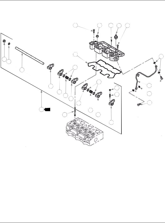
Rocker Arm Assembly
ITEM NO. |
SERVICE |
QTY. |
DESCRIPTION |
|
PART NO. |
||||
|
|
|
||
1 |
120036980 |
1 |
ROCKER ARM ASSEMBLY |
|
2 |
120356200 |
3 |
ROCKER ARM COMPL; INTAKE |
|
3 |
120356210 |
3 |
ROCKER ARM COMPL; EXHAUST |
|
4 |
199486220 |
6 |
SCREW |
|
5 |
020109076 |
6 |
NUT |
|
6 |
120316300 |
1 |
ROCKER ARM SHAFT |
|
7 |
198216780 |
2 |
SPRING |
|
8 |
199280280 |
4 |
SHIM |
|
9 |
015100410 |
1 |
SCREW |
|
10 |
052100120 |
1 |
O-RING |
|
11 |
198436150 |
1 |
PLUG |
|
12 |
140607270 |
1 |
OIL PIPE COMPL |
|
13 |
140996260 |
4 |
GASKET |
|
14 |
198486780 |
2 |
EYE BOLT |
|
15 |
120996150 |
1 |
GASKET |
|
16 |
011310625 |
2 |
BOLT |
|
17 |
023100008 |
3 |
NUT |
|
18 |
012109177 |
3 |
STUD BOLT |
|
19 |
185246250 |
1 |
OIL PRESSURE SWITCH |
|
|
|
|
|
NOTES:
1. Item 1 includes (items 2 -11).
101741 05/09 |
2-5 |
Loading...